1
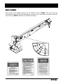
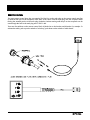
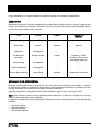
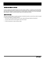
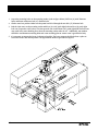
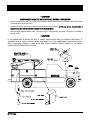
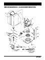
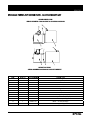
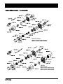
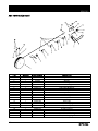
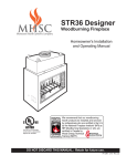
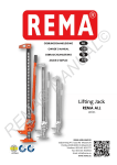
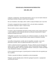
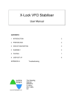
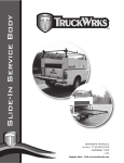
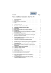
3200 Series Owner’s Manual
As of November 4,2004
3200 SERIES OWNER’S MANUAL
SAFETY
TABLE OF CONTENTS
1
SAFETY
2-4
OPERATION
5-8
MAINTENANCE
9-10
SPECIFICATIONS
11
TROUBLESHOOTING
12
MOUNTING INSTRUCTIONS
13-15
PARTS
16-26
SCHEMATICS
27-28
WARRANTY
29
FOR THE LOCATION OF YOUR NEAREST DISTRIBUTOR CALL 330-264-7441
Revision 6/04
s
2
SAFETY
3200 SERIES OWNER’S MANUAL
- It is YOUR responsibility to maintain and operate this crane safely -
The following words and symbols will be used in your owner’s manual:
! DANGER ! Indicates immediate danger and that special precautions are necessary.
! CAUTION ! Warns against potential hazards or cautions against unsafe practices.
Your s crane is designed to meet all applicable government safety standards. Warranty will be voided if the
crane is misused due to:
•
Overloading
•
Abuse
•
Lack of (or improper) maintenance
•
Unauthorized modification
! CAUTION !
Operate your 3200 crane within the lifting capacities specified. Exceeding the lifting capacity for a given boom
length can cause tipping or structural failure. Only the s “New Machinery and Equipment” warranty shown
on the last page of this manual is valid with this crane. No other warranty—verbal, written, or implied—is valid with
this crane. Treat your s crane with respect and service it regularly. These two things can add up to a safer
working environment and longer equipment life.
! CAUTION !
Note locations of Danger, Caution, and Lift Capacity decals on the 3200 crane. Read and understand each of
these before attempting to operate the crane. If any of these labels are missing or cannot be read, contact your
s distributor for immediate replacement.
3
s
3200 SERIES OWNER’S MANUAL
SAFETY
GENERAL SAFE OPERATING PRACTICES
ALWAYS inspect your crane daily, prior to use, for malfunctions, defects, or misuse.
ALWAYS keep the vehicle as level as possible while loading or unloading.
ALWAYS set the vehicle emergency brake before beginning crane operations.
ALWAYS keep the load as close to the ground as possible.
ALWAYS store the crane and hook when moving the truck.
ALWAYS store the controller securely to avoid unauthorized use of the crane.
NEVER swing a load that passes over people.
NEVER operate the crane within ten feet of a power line.
NEVER exceed the rated lifting capacity. Deduct the weight of any load handling equipment from rated capacity.
NEVER leave a load suspended in the air.
NEVER use the winch to drag a load into position before lifting.
NEVER operate the crane during an electrical storm or when high wind conditions exist.
NEVER side load the boom by dragging a load from the side.
NEVER try to service or repair the crane while the crane is operating.
NEVER place yourself between the load and truck or other fixed object.
NEVER move the truck while operating the crane or with a load on the crane.
SAFETY CHECKLIST
STRUCTURAL SOUNDNESS: Inspect the unit for damaged members and loose fasteners.
CONTROLS: Make a short test for proper control and operation of all functions.
REPAIRS: Fix all problems before using your crane.
LEAKAGE: Examine all of the hydraulic lines for frays and blisters. Look for signs of lubricating or hydraulic oil
leakage.
HYDRAULIC OIL SUPPLY: With the crane in a stored position, and all cylinders retracted, check oil level in the
hydraulic reservoir.
s
4
SAFETY
3200 SERIES OWNER’S MANUAL
DECAL PLACEMENT
Note locations of the DANGER, CAUTION, and LIFT CAPACITY decals on s 3200 cranes. Read and
understand each of these decals before attempting to operate your crane. If any decals are missing or cannot be
read, contact your s distributor for immediate replacement.
5
s
3200 SERIES OWNER’S MANUAL
OPERATION
LOAD CAPACITIES
MEASURED IN POUNDS
CRANE RATING : 10,000 FT./LB.
DISTANCE IN FEET
NOTE: Load capacities are based on 85% of tipping when all outriggers are extended and have
firm contact with a solid surface. Vehicles must have proper axle load distribution and crane
must be mounted in accordance with manufacturer’s instructions.
s
6
OPERATION
3200 SERIES OWNER’S MANUAL
REMOTE CONTROL
The crane remote control plugs into a receptacle. The blue line on the male plug on the remote control must line
up with the flat spot on the receptacle at the base of the crane. Push the male plug onto the receptacle while
turning the serrated portion of the male plug clockwise. Continue turning until the pin on the receptacle can be
seen through the hole in the male plug and a “click” is felt.
There are five switches on the remote control. Each is labeled as to the function and direction. For example: To
activate the winch, push up on the switch to “winch up”; push down on the switch to “winch down”.
7
s
3200 SERIES OWNER’S MANUAL
OPERATION
The 3200 crane is designed to provide excellent service if operated within the maximum allowable load
specifications stated on the unit’s “Angle Indicator Plate” located on either side of the boom. A load chart is also
included on page 5. Load information charts should be studied before operating the crane. Exceeding the stated
load limit can cause tipping or structural failure. You should familiarize yourself with proper operation procedures
to avoid overloading the crane. As an example: If a load of 3200 pounds is lifted at an 11’ boom length at 75°,
lowering the boom would cause an overload situation.
The 3200 crane is relatively simple to operate. Prior to field use, you should familiarize yourself with the controls
and how the unit reacts to the controls. Practice operations should be performed with a light test weight
progressing to a heavier test weight.
LIFTING OVER 1,600 POUNDS
A “two-part” line must be used whenever the load is 1,600 pounds or greater. In order to “two-part” the line:
•
Connect the winch cable eye to the pin on the bottom of the manually extendible boom section.
•
Insert cable through the snatch block by removing the cotter pin and disassembling.
•
Reassemble the snatch block. Be sure to reinsert the cotter pin in the snatch block.
You should also use a “two-part” line for loads under 1,600 pounds if you want to slow down the line speed of
the cable.
LOAD LIFTING
It must be understood that all load ratings are formulated on 85% of tipping. Tipping is defined as a tire breaking
contact with the ground. Further, all load ratings are dependent upon compliance with the following:
•
The unit has been correctly installed in accordance with chassis requirements and truck body manufacturer’s
specifications.
•
The intended operation is carried out on a level, solid surface with proper outrigger placement.
s
8
OPERATION
3200 SERIES OWNER’S MANUAL
TASK PERFORMANCE
1.
Position the 3200 crane as close to the job as possible on a firm, dry, and level surface. Avoid overhead
obstruction on the work side of the unit.
2.
Set the parking brake.
3.
Extend and lower the outriggers until firm ground contact is made. On soft ground, use bearing pads to
prevent sinking or tipping.
4.
Run the winch line out before extending the boom.
5. Make sure the connection to the load is secure and will not come loose when lifting the load.
OVERLOAD PROTECTION
The 3200 crane is equipped with a counterbalance valve inside the lift cylinder to protect against overloading. In
an overload condition, the boom will not elevate. Attempts to winch the load will cause a downward feathering of
the boom until the overload condition is reduced. The counterbalance valve will also keep the boom from coming
down in the unlikely event of a rupture to the hydraulic hoses that supply oil to the lift cylinder.
A pressure sensitive switch is located in the lifting cylinder. It can sense an overload situation. This causes a
shutdown of the winch up, boom extension out, and boom elevation functions, and automatically resets after the
crane has been moved out of the overload position.
An anti-two block feature is provided on the LRX models, and optional on all others.
RELIEF VALVES
The 3200 crane has a relief valve located on the hydraulic power unit. This is the main system relief. It is factory
set at 2550 PSI. The main function of this relief valve is to prevent overloading of the system if the boom is
inadvertently rotated against an immovable object, while one of the other hydraulic functions is also being used.
The relief valves would not normally require adjustment, but if the correct relief valve setting is suspect, refer to
the maintenance section of this manual for the proper adjustment and testing procedure.
9
s
MAINTENANCE
3200 SERIES OWNER’S MANUAL
Proper maintenance on a regular schedule is essential to keep the unit operating at peak efficiency.
LUBRICATION
Maintenance and proper lubrication schedule will vary with climate conditions and the amount of usage the unit
receives. The lubrication chart below is intended to serve for a normal workload and moderate weather variance.
Periods of heavy use shorten service intervals.
ITEM
WHERE
INTERVAL
LUBRICATION
PRODUCT
Slewing Ring
Grease Fitting
1 Month
Chevron Moly Grease #2
Winch Cable
Surface
6 Months
Light Oil
Pulley Block
Not Required
----
------
The Worm and
Gear Mesh
Directly on Gears
1 Month
Sheave Bushing
Not Required
----
Mobiltac “C”, Shell
Cardium EP Silver Streak
200, Mollube Alloy 936
------
Cylinder Pin Bushing
Not Required
----
------
Turret to Boom Bushing
Grease Fitting
6 Months
Chevron Moly Grease #2
HYDRAULIC FLUID SPECIFICATION
Minimum viscosity specifications for hydraulic oil to be used in the crane should be Chevron AW68 or equivalent
to eliminate the necessity of seasonal oil changes under normal temperature conditions. For operations in below
freezing temperature, use a hydraulic fluid having a viscosity of 3000 SSU’s.
Operating temperature of the hydraulic fluid should be within the range of 120°F—160°F (49°C—82°C).
NOTE: Arctic conditions present special requirements and considerations. Consult your oil supplier for the proper
fluid for working under these severe conditions.
In addition to meeting the viscosity requirements, hydraulic fluid used in the system should contain the following
additives:
•
•
•
•
Anti-foam inhibitors
Antioxidant inhibitors
Anti-wear additives
Rust resistant additives
s
10
MAINTENANCE
3200 SERIES OWNER’S MANUAL
PURGING AIR FROM THE SYSTEM
Air that is trapped in the cylinder will cause an erratic “bumpy” condition. To expel the air, hold the affected
control open after the function has “bottomed out”. Move the function in the opposite direction and again hold
the control open. Attempt to operate the crane in a normal manner to determine if the air has been purged.
When purging is complete, reevaluate hydraulic fluid level and add fluid if necessary.
REMOTE CONTROL
The remote control is subject to corrosion and must be checked at least twice a year and more often if operated
in severe, wet conditions. To check for corrosion:
1.
Remove the cover plate and inspect for lack of luster. Metal should appear bright and untarnished.
2.
Spray the inside of the box with an ignition sealer such as Krylon.
3. Check all connections to make sure they are tight.
11
s
2000-R SERIES OWNER’S MANUAL
MOUNTING INSTRUCTIONS
FEATURES
•
Crane Rating: 10,000 ft/lb capacity.
•
Hydraulic extension boom provides reach up to 11’ with manual boom adding an additional 4’.
•
Electric winch for efficient operation.
•
Self-lubricating Nylatron™ bearing allows smooth operation of inner and outer booms.
•
Multifunction, removable remote control provides safe operation up to 25’ away.
•
Electrical solenoid-operated valves.
SPECIFICATIONS
•
Extension:
•
Lifting Height Above Base: 15’
•
Weight:
•
Length:
104.00”
•
Width:
19.00”
•
Height:
33.50”
•
Base Dimensions:
14.00” x 16.00” (10.50” x 14.75” bolt pattern)
•
Rotation System:
360° continuous hydraulic - turntable bearing w/planetary drive & dynamic brake.
•
Remote Control:
Lightweight remote control unit with 25’ cable.
•
Winch Cable:
62’ of 1/4” aircraft cable, with latch hook traveling block and down haul weight.
•
Rotation Speed:
1 RPM.
•
Boom Elevation Speed:
-5° to +75° - 15 seconds.
•
Boom Extension Speed:
11’ to 15’ - 18 seconds.
•
Winch Line Speed:
15’ per minute - single line.
•
Min. Chassis Req.:
8000 GVWR.
Electric to 11’ - with manual extension to 15’.
800 lbs.
OUTRIGGER REQUIREMENT
Jackleg or outrigger available.
s
12
SPECIFICATIONS
13
3200 SERIES OWNER’S MANUAL
SYMPTOM
PROBABLE CAUSE
Function fails to respond to controls
Pressure switch malfunctioning
Low hydraulic fluid
Faulty hydraulic pump
Short circuit in remote control
Crane not grounded to truck
Solenoid in control valve malfunctioning
Bad ground on control valves
Circuit breakers tripped
Dead battery
Optional anti-two block malfunctioning
Slow down of functions speed
Relief valve set too low
Low hydraulic fluid
Clogged filter/strainer
Pump not providing enough GPM
Boom drifts under load
Cylinder piston seals leaking
Counterbalance valve defective
Crane is overloaded
Boom or winch will not lift load
Restriction in hydraulic line
Cylinder piston seals leaking
Relief valve not set properly
Pump losing prime
Overload condition
Filter clogged
Counterbalance valve defective
Cable mis-wrap
Loose cable being wound on drum
Unusual noise during operation
Cavitation due to low hydraulic oil
Load is excessive
Suction line filter is clogged
Relief valve set too low
Relief valve defective
Air in the lines
Winch motor runs but fails to wind cable
Gear train is damaged
Erratic operation of hydraulic function
Air in hydraulic system
Crane will not rotate
Low hydraulic fluid
Hydraulic motor defective
Bad ground on control valve
Rotation speed too fast or too slow
Flow controls set incorrectly
Control valve defective
s
3200 SERIES OWNER’S MANUAL
MOUNTING INSTRUCTIONS
! CAUTION !
Improperly mounted cranes can injure people or damage property. These instructions describe installation of a
s crane on a typical s service body. Contact the dealer for other service body/truck chassis
combinations.
! CAUTION !
The truck chassis must be capable of safely supporting the entire chassis, body, crane, other equipment and the
maximum capacity of the crane - 3200 pounds.
s 3200 cranes must be installed on a truck chassis with a GVWR of at least 8000 pounds. The GVWR must
exceed the curb weight of the complete vehicle by at least the rated load of the crane (3200lbs). The curb weight
is the total weight of the chassis, body, crane, and other equipment. (See example below.)
GVWR = 8800LBS
CURB WT. = BODY WT. (1200 LBS) + CRANE WT. (800 LBS) + CHASSIS WT. (3500 LBS) = 5500 LBS
GVWR (8800 LBS) – CURB WT. (5500 LBS) = 3300 LBS > 3200 LBS
! CAUTION !
Never attach, change, or use unauthorized components on your s crane. This could result in failure
of the crane and/or possible injuries and voids any warranty or liability.
! CAUTION !
MOST SERVICE BODIES ARE NOT STRONG ENOUGH TO MOUNT A CRANE!
You must reinforce the compartment and floor before you mount the crane. Get help from the truck dealer or
distributor if the s 3200 crane is installed on a non-s body, in another body/chassis combination or
in a different location. It is recommended that a s crane body and outriggers be used with the 3200 crane.
Consult the distributor for the proper body required for your application.
s
14
MOUNTING INSTRUSTIONS
3200 SERIES OWNER’S MANUAL
1. Layout the mounting holes on the mounting surface (refer to figure below). Drill four (4) 0.56” diameter
holes and flame cut the two inch (2”) diameter hole.
2. Lift the crane into position. Make sure the power lead is fed through the two inch (2”) diameter hole.
3. Bolt the 3200 crane to the mounting surface with four (4) 0.50” grade eight bolts and four (4) grade eight
lock nuts. Torque the 0.50” bolts to 100 foot pounds. Use of other than 0.50” grade eight bolts and lock nuts
may result in the crane breaking loose from the mounting surface when in use. Additionally, star washers
should be used between mounting bolts and crane mounting plate to ensure crane is grounded to body.
4. It is necessary to support the boom in the stored position. The boom support should also have a place to
secure the hook in the stored position. The figure below shows a typical boom support.
15
s
3200 SERIES OWNER’S MANUAL
MOUNTING INSTRUCTIONS
! CAUTION !
-DISCONNECT NEGATIVE BATTERY CABLE BEFORE PROCEEDING5.
Run the power lead to the front of the truck. Locate the lead so that it will be protected. Install cable clamps
to hold the wire securely in place.
6.
Connect the power wire to the positive terminal on the vehicle battery. A 250-amp in-line circuit breaker is
required near the battery to protect harness from electrical shorts.
7. Reconnect the negative battery cable. The 3200 crane is self-grounding and does not require an additional
ground cable.
! CAUTION !
IF THE POWER WIRE IS ROUTED SO THAT IT PASSES THROUGH ANY BODY OR CHASSIS SHEET METAL, A
GROMMET MUST BE USED TO PROTECT WIRES FROM BEING CUT. IF THE POWER WIRE COMES INTO CONTACT
WITH A GROUNDED SURFACE, A DEAD SHORT WILL OCCUR POSSIBLY CAUSING DAMAGE TO THE CRANE,
VEHICLE BATTERY OR ELECTRICAL SYSTEM.
s
16
PARTS
3200 SERIES OWNER’S
MANUAL
TURRET AND BASE SERVICE PARTS - ILLUSTRATION (PLASTIC SHROUD OPTION)
17
s
PARTS
3200 SERIES OWNER’S MANUAL
TURRET AND BASE SERVICE PARTS - PART LIST (PLASTIC SHROUD OPTION)
ITEM
1
2
3
4
5
6
7
8
9
10
11
12
13
14
15
16
17
18
19
20
21
22
23
24
25
26
27
28
29
30
31
32
s
QUANTITY
16
1
1
1
15
1
8
1
1
1
2
1
2
1
1
1
12
4
7
25’
4
1
1
4
1
1
3’
1
25’
1
4
12
7
1
4
1
1
1
PART NUMBER
964050
95477-001
95483-001
95484-001
964047
95476-001
964049
95468-001-L
95468-001-R
95418-001
917453
95420-001
919874
95618-006
95403-001
961675
961676
961679
961677
961762
963941
963942
95699-014
95457-001
95472-001
960680
961758
95453-001
961758
95618-007
95618-009
95618-010
95618-008
95907-400
95907-424
95907-425
95907-426
95907-429
DESCRIPTION
5/8”-11 x 2.00” screw
Base weldment
Slewing ring
Rotation drive
5/8” - 11 x 3.00” SCREW
Turret weldment
1/4” - 20 x 1/4” ss screw
Crane cover-left hand
Crane cover-right hand
Harness
1/2” -13 x 2.00” screw
Hydraulic motor
1/2 “ Lock washer
Dust cap
Remote control
Male plug
16 gauge socket
12 gauge socket
Seal plug
Cable
Rocker switch-spdt-(on/off/on)
Rocker switch-spst-(on/off)
Angle-power rotation
Clamp-hose
Angle-power rotation upper
Copper lug
Cable-1 gauge-red
Tweco-connector assembly
Cable-1 gauge -red
Receptacle
12 gauge pin
16 gauge pin
Seal plug
Remote control (new style)
Switch-momentary
Switch-maintained
Cable-remote control
Casing-remote control
18
PARTS
3200 SERIES OWNER’S
MANUAL
TURRET AND BASE SERVICE PARTS - ILLUSTRATION (METAL SHROUD-STANDARD)
19
s
PARTS
3200 SERIES OWNER’S MANUAL
TURRET AND BASE SERVICE PARTS - PART LIST (METAL SHROUD-STANDARD)
ITEM
1
2
3
4
5
6
7
8
9
10
11
12
13
14
15
16
17
18
19
20
21
22
23
24
25
26
27
28
29
30
31
32
33
34
35
36
37
38
39
40
s
QUANTITY
16
1
1
1
15
1
1
6
1
2
2
1
1
1
20
1
4
1
1
2
2
2
2
8
4
1
1
1
1
1
4
12
7
1
1
1
1
12
4
7
1
4
1
1
1
6’
PART NUMBER
964050
95477-001
95483-001
95484-001
964047
95476-001
95468-004
962111
95499-024
917453
919874
95420-001
95907-195
95453-001
961767
95699-014
95457-001
95472-001
95419-001
917351
152608
917353
917352
919870
919723
95907-136
95419-012
95168-022
95418-001
95618-007
95618-009
95618-010
95618-008
95618-006
95907-400
95907-426
961675
961676
961679
961677
95907-425
95907-424
95907-429
95907-467
960680
961758
DESCRIPTION
5/8”-11 x 2.00” screw
Base weldment
Slewing ring
Rotation drive
5/8” - 11 x 3.00” SCREW
Turret weldment
Shroud base
Self tapping screw – 10-24 x 3/8
Shroud – valve cover
1/2” -13 x 2.00” screw
½” lock washer
Hydraulic motor
Seal kit-hydraulic motor
Tweco connector assembly
Cable-1 gauge -red
Angle-power rotation weldment
Clamp-hose
Angle-power rotation upper
12-volt hydraulic power unit
3/8-16 x ¾ hex head cap screw
3/8 external tooth lock washer
3/8-16 x 1.25 hex head cap screw
3/8-16 x 1.00 hex head cap screw
3/8 flat washer
3/8-16 lock nut
Bracket-pump mounting
Grommet
Shroud – solenoid
Harness
Receptacle
12 gauge pin
16 gauge pin
Seal plug
Dust cap
Remote control (new style)
Cable-remote control
Male plug
16 gauge socket
12 gauge socket
Seal plug
Switch-maintained
Switch-momentary
Casing-remote control
Face plate
Copper solder lug
Cable-1 gauge-red
20
PARTS
3200 SERIES OWNER’S
MANUAL
BOOM ASSEMBLY SERVICE PARTS - ILLUSTRATION
21
s
3200 SERIES OWNER’S MANUAL
PARTS
BOOM ASSEMBLY SERVICE PARTS - PARTS LIST
ITEM
1
2
3
4
5
6
7
8
9
10
11
12
13
14
15
16
17
18
19
20
21
22
23
24
25
26
27
28
29
30
31
32
33
34
35
36
37
38
39
40
41
42
43
44
45
46
s
QUANTITY
8
1
2
2
6
6
1
1
2
2
2
2
1
1
1
1
2
1
1
1
1
1
3
3
1
2
1
2
1
2
2
1
2
1
6
1
1
1
1
1
2
2
4
1
5
1
PART NUMBER
95456-001
95499-023
95415-001
95417-001
95079-001
95421-001
95431-001
95475-001
95459-001
917494
919003
95480-001
95416-001
95416-002
95435-001
95461-001
95458-001
95499-001
95499-003
95410-001
95422-004
95422-003
925063
95424-002
95427-001
95422-001
95411-001
95428-001
95413-001
95907-197
95460-001
95401-002
917326
95487-001
95499-015
95907-231
95499-016
963940
918388
917155
919505
962111
95440-001
919874
919864
DESCRIPTION
Snap ring – 1.00” shaft
Hoist
s decal
3200 LRX decal
Large boom plug
Small boom plug
Main boom weldment
Black striping decal
1.00” boom pin
1/4”-20 x 3/4” hex head cap screw
1/4” - 20 nut
Arrow
Load chart – 3200 Left hand
Load chart – 3200 right hand
Hydraulic boom weldment
Extension cylinder pin
Snap ring – 3/4” shaft
12” lanyard
1/2” x 3.50” Clevis pin
Jib end sheave
3/8” x 1.75” Clevis pin
3/4” x 2.00” Clevis pin
2.31” cotter pin
2.68” cotter pin
Snatch block complete
1/2” Clevis pin
Pulley block sheave
Spacer
Hook with catch
Clevis pin with grease fitting - 3/4” x 2.00”
1.00” turret pin
1/4” diameter X 62’ cable
¼-20 x 0.50 hex head cap screw
Plate-stop, front
M12 x 1.75 8.8 metric bolts 1.18” (30mm) long
Cover mounting bracket
Contactor-hoist-12 volt
Cover contactor
Relay-12 volt
3/16 x 5/16 aluminum pop rivet
10-24 x ½ round head machine screw
10-24 lock nut
Self tapping screw – 10-24 x 3/8
Manual boom assembly
½” lock washer
¼” lock washer
22
PARTS
3200 SERIES OWNER’S
MANUAL
HYDRAULIC COMPONENT SERVICE PARTS - ILLUSTRATION
23
s
PARTS
3200 SERIES OWNER’S MANUAL
HYDRAULIC COMPONENT SERVICE PARTS - PARTS LIST
ITEM
QUANTITY
PART NUMBER
DESCRIPTION
1
2
3
4
5
6
7
8
9
10
11
12
13
14
15
16
17
18
19
20
21
22
23
24
25
26
27
28
1
1
2
4
1
1
1
1
1
1
2
1
1
2
4
1
7
1
2
1
1
1
1
1
1
8
1
1
95484-001
95420-001
95488-003
95488-005
95498-005
95498-007
95498-008
95498-006
95488-004
95419-001
95488-010
938814
938815
95498-010
95488-001
95408-001
95488-006
95482-001
95498-009
95407-001
95498-001
95498-002
95498-004
95498-003
95488-009
903124
95907-177
95907-176
Rotation drive
Hydraulic rotation motor
Male elbow-3/8 JIC to 7/8 o-ring
Bulkhead union-3/8 tube to 3/8 JIC
Tube – valve to lift
Tube – valve to lift
Tube – valve to pump
Tube – valve to pump
Male connector-3/8 pipe to 3/8 JIC
12-volt hydraulic power unit
Male connector-3/8 tube to 9/16 o-ring
Filter housing
Filter
33” hose
Male connector-3/8 JIC to 9/16 o-ring
Extension cylinder
Positionable elbow-3/8 tube to 9/16 o-ring
Valve – 3200
18” hose
Lift cylinder
Tube – valve to motor
Tube – valve to motor
Tube – valve to extension
Tube – valve to extension
Male elbow-3/8 pipe to 9/16 o-ring
Bushing-16du16
Seal-kit-extension cylinder
Seal-kit-lift cylinder
29
30
31
32
33
34
35
36
37
2
1
1
4
1
6
2
1
1
95907-093
95723-003
95907-195
95907-331
95907-192
95907-297
95907-199
95907-171
95907-098
Counter balance valve
Pressure switch
Seal kit
Nut
Cartrage-4 way #8 (rotation port)
Solenoid –12v #8
Cartrage-4way #8 (cylinder ports)
Dump valve cartrage-2 way
Solenoid – 10v #8 (dump valve)
s
24
PARTS
3200 SERIES OWNER’S
MANUAL
HYDRAULIC POWER UNIT SERVICE PARTS - ILLUSTRATIONARTS LIST
OLDER SERIES PUMP
SERIAL NUMBERS 1990-C4432007 & C4432009-C44320026
NEW STYLE PUMP
SERIAL NUMBERS C4432008 & C4432027-PRESENT
25
ITEM
QUANTITY
PART NUMBER
DESCRIPTION
1
2
3
4
5
6
7
1
1
1
1
1
1
1
95907-517
95907-519
95907-518
95907-516
95907-522
95907-521
95907-520
Reservoir -1 gallon
Breather cap – reservoir
Starter solenoid
Motor 12 volt
Valve manifold
Mounting bracket
Pump
8
9
10
11
12
1
1
1
1
1
95907-490
95907-173
95907-143
95907-191
95907-491
Reservoir – 1 gallon (old style)
Breather cap – reservoir (old style)
Starter solenoid (old style)
Motor – 12 volt (old style)
Pump (old style)
s
PARTS
3200 SERIES OWNER’S MANUAL
WINCH SERVICE PARTS - ILLUSTRATION
MODEL # DC2000-LF
SERIAL C4632052 THRU C4632061
SERIAL C4632067 THRU C4932046
MODEL # DC1600
SERIAL C4432001 THRU C4632051
SERIAL C4632062 THRU C4632066
SERIAL C4932047 THRU CURRENT
s
26
PARTS
3200 SERIES OWNER’S
MANUAL
ANTI TWO-BLOCK PARTS
ITEM
1
2
3
4
5
6
7
8
9
10
11
12
13
14
15
16
17
18
19
21
27
QUANTITY
1
1
1
3
4
1
1
1
1
2
1
2
1
1
6
1
1
1
1
1
2
PART NUMBER
95467-001
95493-012
927204
95493-006
95493-005
95422-005
95493-015
95424-001
95493-002
919717
95493-003
917144
95493-007
95493-004
962110
960802
919001
95493-013
917092
95493-011
962111
DESCRIPTION
Cord reel
Bushing bracket—winch
Bushing
Bracket bushing – main
Short bushing
Clevis pin
Cable Guide Weldment
Cotter pin
Waterproof switch
8-32 lock nut
Switch holder – genelco
8-32 x 1/2” screw
Cover
Strain relief
¼-20 x 3/8” self tapping screw
Nylon tie strap
8-32 nut
Bracket cord reel
8-32 flat head screw
Hydraulic bracket bushing
10-24 x 3/8” self tapping screw
s
3200 SERIES OWNER’S MANUAL
SCHEMATICS
HYDRAULIC SCHEMATIC
s
28
SCHEMATICS
3200 SERIES OWNER’S
MANUAL
WIRING DIAGRAM
29
s
ONE – YEAR LIMITED WARRANTY
COVERED PRODUCTS:
s Crane – One (1) year from the date of purchase by the original owner of record for s parts including the
structural integrity of the crane boom assembly, turret assembly, and base plate weldment. Product(s) not made of
galvaneal steel are warranted to the original owner of record for 180 days from the date of purchase.
Should the warranted product rust through s will cover labor and materials to replace and/or repair defective
materials and/or install new materials (solely at the discretion of s)
The foregoing collectively constitutes the “Warranty”.
ELIGIBILITY.
This Warranty shall only apply to products listed herein and initially purchased after June 1, 1995
Product(s) warranted must be properly maintained and serviced under the guidelines recommended in the owner’s
manual. The original owner must complete and submit the warranty registration card within thirty (30) days of
purchase.
This Warranty applies only when an authorized s up fitter properly installs the product, and it is used for the purpose
for which it was designed.
This Warranty is not transferable.
EXCLUSIONS
This Warranty applies to s Cranes only and excludes all items supplied by distributors or mounting stations including,
but not limited to finish paint, lettering, installation, wiring, optional parts, modifications and the like.
Product(s) that have been misused, abused, altered, or intentionally damaged.
SPECIFIC “NO RUST, NO BUST” WARRANTY EXCLUSIONS
Product(s) must have perforation in the metal. Rust in the paint or surface rust is not considered rust through.
Product(s) purchased in prime paint condition.
Product(s) purchased and used outside the United States and Canada.
Product(s) used to carry corrosive materials.
s shall not be liable to the original owner/user or any third party for any direct or indirect, incidental or
consequential damages including, but not limited to, transportation costs, lost profits, and loss of income, as a result
of a vehicle being out of service.
WARRANTY CLAIMS PROCEDURE
Claims may be handled by contacting your nearest authorized s distributor. All claims are to be filed in writing and
will be administered through a s distributor. All repairs must be authorized by s prior to any work being
performed and must be done by an authorized s distributor or by a person or company pre-approved by s in writing.
s reserves the right to inspect products returned by the original owner under this Warranty to determine
whether the product is covered. Inspection shall, at s’s option, be performed at the factory, or at such other
reasonable place as may be designated by s, and in such event freight for returning products shall be paid by the
original owner. s also reserves the right to require dated proof of purchase from the original owner.
Unauthorized repair or replacement prior to inspection or repair or replacement not in accordance with s
recommendations and procedures may void the Warranty.
.
DISCLAIMER OF IMPLIED WARRANTIES; LIMITATIONS OF REMEDIES:
THERE ARE NO OTHER WARRANTIES, EXPRESSED OR IMPLIED, GIVEN BY s FOR THIS PRODUCT. IMPLIED WARRANTIES OF
MERCHANTABILITY AND FITNESS FOR A PARTICULAR PURPOSE ARE SPECIFICALLY DISCLAIMED. THE PURCHASER’S REMEDIES
FOR LOSS, DAMAGE, OR EXPENSE RESULTING FROM THE USE OR MISUSE OF THIS PRODUCT ARE LIMITED TO THOSE
EXPRESSED IN THIS LIMITED WARRANTY.
THIS LIMITED WARRANTY GIVES PURCHASER SPECIFIC LEGAL RIGHTS, AND PURCHASER MAY ALSO HAVE OTHER RIGHTS,
WHICH VARY FROM STATE TO STATE. SOME STATES DO NOT ALLOW DISCLAIMERS OF OR LIMITATIONS ON IMPLIED
WARRANTIES OR THE EXCLUSION OR LIMITATIONS OF INCIDENTAL OR CONSEQUENTIAL DAMAGES, SO THE ABOVE
DISCLAIMER AND LIMITATION MAY NOT APPLY TO PURCHASER
s
30