1
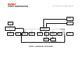
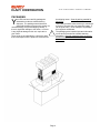
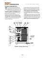
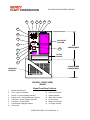
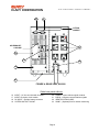
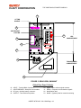
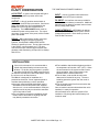
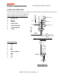
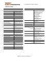
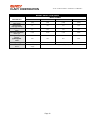
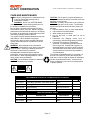
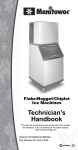
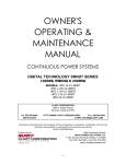
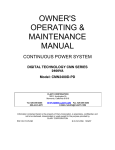
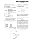
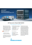
OWNER'S
OPERATING &
MAINTENANCE
MANUAL
UNINTERRUPTIBLE POWER SYSTEM
GLOBAL SN SERIES UPS
1,000VA THROUGH 2,000VA
MODELS:
SN1000
SN1250
SN1500
SN2000
Manufactured by
THE CONTINUOUS POWER COMPANY
Sold Exclusively Through
NOVA POWER SOLUTIONS, Inc.
11367 Sunset Hills Road, Reston, VA 20190
Tel: (703) 742-0000 • Fax (703) 742-4003
email: [email protected]
Information contained herein is the property of Clary Corporation, is proprietary, confidential, and not to be disclosed,
disseminated or used except for the purpose provided by
CLARY CORPORATION
P/N 510-12580
A
RD-12/29/03
THE CONTINUOUS POWER COMPANY
TABLE OF CONTENTS
TITLE
PAGE
TABLE OF CONTENTS
1
INTRODUCTION
3
TECHNICAL DESCRIPTION
4
PACKAGING
6
PHYSICAL DESCRIPTION
7
SUMMARY OF INDICATORS AND CONTROLS
11
INSTALLATION
12
OPERATION
13
SIGNALS AND INTERFACING
14
SPECIFICATIONS
15
CARE AND MAINTENANCE
17
SERVICE AND REPAIR
18
WARRANTY
19
THE CONTINUOUS POWER COMPANY
INTRODUCTION
C
ongratulations! You have selected the
highest quality protection for your continuous
power needs. This unit offers a quiet and
compact package with superior performance
you can depend on. You now own a SN Series
Continuous Power System (CPS) which is an all
Digital Technology product manufactured by Clary
Corporation, the first name in uninterruptible power
system (UPS) reliability. The Continuous Power
System is the highest order in the hierarchy of UPS
products. When power problems occur, there can
be no compromising the reliability of your power
solution. The SN Series Continuous Power System
is your complete power solution.
This Users Manual is provided with your new SN
Series unit. It will enhance your understanding of
the product and its functions. Read this handbook
carefully in the order it is presented prior to
operating your unit. This will save you time and
effort in your installation and application. The
illustrations will also familiarize you with this unit’s
operating modes and indications. Always operate
the unit within the guidelines and specifications
given to maximize the unit's efficiency and lifetime.
Also, your understanding of the product is essential
in providing you years of service for your continuous
power requirements.
This unit has been manufactured and tested to meet
specific safety standards. It meets UL and FCC
requirements and complies with safety performance
standards.
IMPORTANT SAFETY INSTRUCTIONS,
SAVE THESE INSTRUCTIONS
This symbol indicates that
dangerous voltage constituting
a risk of electrical shock is
present within the unit.
!
This symbol indicates that there
are important operating and
maintenance instructions in the
literature accompanying this
unit.
CAUTION
RISK OF ELECTRIC
SHOCK DO NOT OPEN
!
This manual contains important safety instructions that should be followed during installation and maintenance of
the UPS and batteries. Be aware of the following symbols and their meaning as they appear throughout the
manual:
This equipment generates and uses radio frequency energy and if not
installed and used properly in strict accordance with the manufacturer's
instructions, may cause interference to radio and television reception. All
units in this manual have been tested and found to comply with the limits
for a Class A computing device in accordance with the specifications in
Subpart J of Part 15 of FCC Rules, which are designed to provide
reasonable protection against such interference in a commercial
installation. However, there is no guarantee that interference will not occur
in a particular installation. If this equipment does cause interference to
radio and television reception, which can be determined by turning the
equipment off and on, the user is encouraged to try to correct the
interference by one or more of the following measures:
Reorient the receiving antenna.
Relocate the UPS with respect to the receiver.
Move the UPS away from the receiver.
Plug the UPS into a different outlet so that the UPS
and receiver are on different branch circuits.
If necessary, the user should consult the dealer or an experienced
radio/television technician for additional suggestions. The user may find
the following booklet prepared by the Federal Communications
Commission helpful:
"How To Identify and Resolve Radio-TV Interference Problems"
This booklet is available from the U.S. Government Printing Office,
Washington, DC 20402, Stock No. 004000003454.
Page 3
THE CONTINUOUS POWER COMPANY
TECHNICAL DESCRIPTION
T
Reference the block diagram for a simplified
explanation of the system’s operation. The AC utility
source is connected to the power and microelectronics when the input switch is closed. The
input line is filtered, power factor corrected and
rectified for enhanced performance without
disturbing other equipment that may share the same
utility circuit. In SN units, an input isolation
transformer is added to accept a wide range of input
voltages for global applications. Output
transformers, SNMP adapters and many other
options are available.
The microprocessor controls an Inverter Generator
that produces a low harmonic, AC sinewave for
continuous power applications.
When the input AC utility line fails, the battery circuit
within this system takes over to ensure continuous
power. Only after properly rated power is returned,
does the microprocessor reconnect the input source
back into the system.
The microprocessor is directly tied to an external
RS232 connector port. This allows the user to
monitor and even set some of the operating
parameters. With a simple link to a personal
computer using the SNConfig software program, you
can actually view, on your monitor, the event history
of the power distribution system with the SN Series
unit as the central hub. More sophisticated users
may implement the optional SNMP package to
accomplish full Network Power Management.
he SN Series Continuous Power System
(CPS) is a revolutionary new concept in total
power protection and management. The SN
Series is a microprocessor-based UPS that
now allows the user to set most of the control
feature parameters. By directly linking a personal
computer to the SN Series RS232 port, frequency
settings and operation, alarm signals, load
switching, fan operation, etc. can all be programmed
to meet specific application requirements.
The SN Series is a true on-line, continuous power
UPS. In the tradition of Clary products, the SN
Series generates the same high quality and proven
reliability to provide the best power protection
available for today’s critical applications.
In keeping with state-of-the-art design, the power
electronics are completely governed by an on-board
microprocessor. Given the powerful memory
capability of today’s microcontrollers, this
microprocessor has evolved the UPS into an all-inone complete power distribution and monitoring
center. Not only is your critical load insured of the
most reliable and constant power available, but the
user may now continuously track status of the
supply components that keep the entire system
operational. Production downtime can now be
virtually eliminated by knowing exactly what patterns
the supply utility power maintains and by knowing
exactly the condition and life expectancy of the
battery reserve.
Page 4
THE CONTINUOUS POWER COMPANY
DB-9
CONTACTS
UTILITY
INPUT
DB-9
RS232
AUTO
VOLTAGE SELECTOR
SWITCH
INPUT
TRANSFORMER
MICROPROCESSOR
CONTROLLER
COMMON
MODE
CHOKE
VOLTAGE
WINDOW
DETECTOR
POWER
FACTOR
CORRECTOR
RECTIFIER
EMERGENCY
CUTOFF
SWITCH
+ DC
RAILS
AC
INVERTER
GENERATOR
STANDBY
BATTERY
CHARGER
BYPASS LINE
FIGURE 1: SN SERIES BLOCK DIAGRAM
COMMON
MODE
CHOKE
LOAD
THE CONTINUOUS POWER COMPANY
PACKAGING
Y
our UPS has been carefully packaged to
withstand most abuse sustained during
shipment. The packing material has been
specifically designed to protect this system for
normal handling, using most shipping carriers. If
there is significant damage to the carton, or if there
is any physical damage to this unit, report this to
your carrier.
These units are encapsulated in a protective wrap
that comes apart once the product is removed from
!
Page 6
the shipping carton. Save all packing material for
future use.
Take extra precaution when removing or returning it
to the box. Because this unit contains a battery, it
can be quite heavy. Never attempt to unpackage
the equipment unassisted.
The packaging also contains important information
on use and care as well as valuable warranty
information. Read all materials before storing this
literature with your other valuable product
documents.
THE CONTINUOUS POWER COMPANY
PHYSICAL DESCRIPTION
T
his section will point out and illustrate the
various indicators, functions and controls of
the SN Series UPS. Pictured is the front view
of the system, then followed by the rear view.
The important attributes of the SN Series unit are
numbered to assist you in locating them on your
machine and also to fully explain its function and
how it relates to system operation.
Numbers on the drawing will correspond to the
operating component’s name at the bottom with a
brief identification. In the next section, a complete
explanation of all numbered items will be enhanced
to ensure you have a full understanding of the
operation of this system.
8
9
10
Visual indicators used on the front panel are long
lasting, very efficient, light emitting diodes (LED).
When operating the push-button switches, always
hold the switch in for at least two seconds to insure
function confirmation. This feature has been
implemented into the system design to avoid
inadvertent operation of any of the user-available
functions.
The rear panel has been engineered with the user’s
multiple applications in mind. In some models, two
of the output receptacles have been rotated to allow
attachment of a plug-in transformer without hanging
over the back of the unit or interfering with another
outlet. The outputs can be switched on or off.
6
11
7
13
12
14
3
2
AIR INTAKE,
COOLING
4
15
5
LIFTING
HANDLE
1
FIGURE 2: FRONT VIEW, SN1000
Page 7
THE
THE CONTINUOUS
CONTINUOUS POWER
POWER COMPANY
COMPANY
8
9
10
11
6
7
13
12
14
Bypass
Load
Replace
Test
Silence
Fault
Cold
Start
AIR INTAKE,
COOLING
Inverter
Batt.
Level
Battery
On
AC In
AC
Output
0%
100%
Overload
3
Load
Level
2
15
100%
4
UPS
COMPARTMENT
LIFTING
HANDLE
5
1
TRANSFORMER
COMPARTMENT
MOUNTING
BRACKET
FIGURE 3: FRONT VIEW,
SN2000
Global Front Panel Callouts
1
2
3
4
5
6
7
8
System On/Off switch
AC In - Input line indicator
Inverter - Inverter operating indicator
Battery Level - Charge/discharge indicators
Load Level - Output capacity indicators
Cold Start - DC start switch
Cold start acknowledge indicator
Test switch
9
10
11
12
13
14
15
Test indicator
Load On/Off switch
Bypass indicator
Alarm Silence switch
Fault indicator
Battery On indicator
AC output indicator
INSERT INTO DOC. 510-12580-Page –8-
THE CONTINUOUS POWER COMPANY
20
21
LIFTING
HANDLE
AIR EXHAUST,
COOLING
19
23
17
16
18
22
FIGURE 4: REAR VIEW, SN1000
Global rear panel callouts
16
17
18
19
INPUT – AC line cord inlet with lockdown
INPUT- Dual pole circuit breaker
DC INPUT - Auxiliary battery connector
SYSTEM OUTPUT-120VAC
20
21
22
23
Page 9
SIGNAL - Open-collector signal contacts
RS232 - Computer communications signals
IDENTIFICATION LABEL
SNMP – (Optional) Slot for network monitoring
THE CONTINUOUS POWER COMPANY
21
LIFTING
HANDLE
20
AIR EXHAUST,
COOLING
19
23
UPS
COMPARTMENT
17
18
16
TRANSFORMER
COMPARTMENT
22
FIGURE 5: REAR VIEW, SN2000HT
Global Rear Panel Callouts
16
17
18
19
INPUT – Terminal Block 3 position
INPUT BREAKER - Dual pole circuit breaker
DC input - Auxiliary battery connector
OUTPUT - Terminal block 4 position
20
21
22
23
Signal - Open-collector signal contacts
RS232 - Computer communications signals
Identification label
SNMP – (Optional) Slot for network monitoring
INSERT INTO DOC. 510-12580-Page –10-
THE CONTINUOUS POWER COMPANY
SUMMARY OF INDICATORS AND CONTROLS
INPUT POWER - This is system input AC power
protection and interruption for both hot and neutral
lines. This is a circuit breaker that if tripped, unit
operation will continue on battery reserve. This
circuit breaker is rated at 20A.
SYSTEM ON/OFF - This is system input enable
switch. This switch is used to power down the
system. This switch must be in the ON position in
order to AC or DC start the UPS.
LOAD - Four green L.E.D.s and one red
OVERLOAD L.E.D. that illuminate to update status
of the amount of load the INVERTER is powering at
the UPS system output. Each green L.E.D.
represents approximately 25% of full load. As more
load is added to the UPS, the L.E.D.s will
sequentially turn "ON" until the red L.E.D. comes
"ON". This indicates an OVERLOAD situation and
the system will discontinue operation shortly.
BATTERY - Four green L.E.D.s and one green
LOW BATTERY L.E.D. that illuminate to update
status of the battery energy available during a power
outage. Each green L.E.D. represents
approximately 20% of battery reserve power
available. As battery discharge continues, the
L.E.D.s will sequentially turn "OFF" until the last
L.E.D. starts to flash. This indicates a LOW
BATTERY situation and the system will discontinue
operation shortly. Once utility power is returned to
the system, this bar graph will show an approximate
battery state as it reaches full charge.
COLD START - This is a momentary, two position
push button keyswitch. If no AC utility voltage is
available, it may still be a requirement to initialize
some equipment. When this switch is pressed in for
at least two seconds, the system will start up on
battery power. The SYSTEM ON/OFF Switch must
be in the ON position for this function to operate.
The green L.E.D. above this switch will light only
while the switch is held in.
LOAD ON/OFF - This is a momentary, twoposition push button keyswitch. When the system
initially powers up for the first time no INVERTER
generator power will be present at the output load
receptacles at the rear panel. Once this switch is
pressed in for at least two seconds, output power
will then be enabled to the rear panel outlets. If the
system should be powered down for any reason
other than with the SYSTEM ON/OFF Switch, the
output state of these outlets will be remembered by
the internal microprocessor and the UPS will start up
with the output in the state it was last left. The
output neon lamp, in the center of the panel, will light
when the output has been enabled.
BYPASS - A red L.E.D. above the AC OUTPUT
Switch will light to indicate when the system output
is operating in the filtered, emergency BYPASS
mode. This is an unprotected power source that will
not support the load in the event of a power failure.
SILENCE - This is a momentary, two position push
the INPUT POWER Circuit Breaker and the
SYSTEM ON/OFF switch are closed and there is
utility power present at the input of the system.
button keyswitch. During a system FAULT or power
failure, an audible alarm will be present. If a FAULT
condition occurs, the red L.E.D. above this switch
will light. Once this switch is pressed in for at least
two seconds, the audible alarm will be silenced. The
L.E.D. above the switch will remain unchanged.
BATTERY ON - A red L.E.D. that is illuminated
TEST - This is a momentary, two position push
AC IN - A green L.E.D. that is illuminated when both
when the AC input is interrupted to the power
electronics either externally or internally from the
microprocessor due to an out-of-range situation.
The output load is then supported entirely by battery
energy through INVERTER operation.
INV - A green L.E.D. that illuminates when the
INVERTER generator is operating and available to
deliver power to the system output.
button keyswitch. Battery condition is vital to the
UPS performance, particularly during a power
outage. During normal operation and if the Battery
Bar Graph shows the battery at a full charge, this
function switch may be used. By pressing this
switch in for at least two seconds, a battery
acceptance diagnostic will be run by the internal
microprocessor. If it has been discovered that the
battery is excessively fatigued, the red L.E.D. above
this switch will light advising the user to replace the
internal battery or DC supply. The system will run
this test on its own approximately every 24 hours.
INSERT INTO DOC. 510-12580-Page –11-
THE CONTINUOUS POWER COMPANY
AC OUTPUT - A green neon lamp that will light to
indicate output power is present at the load
receptacles.
OUTPUT - A four (4) position terminal block is
provided for the UPS output connection. Continuous
power is provided here and is monitored by the
LOAD L.E.D.s as long as the INVERTER is
functioning. The LOAD ON/OFF Switch must be
enabled for power to be present here. The output
neon lamp, in the center of the panel, will be lit when
power is available.
INPUT – A three (3) position terminal block is
provided for the UPS input connection.
DC INPUT - An interface connector provided for
additional, external battery connections. Additional
batteries may be added to increase load run times
during a utility power failure.
SNMP INTERFACE - (OPTIONAL) An add-on
card that provides sophisticated system network
management protocol. Direct hook-up is via an
RJ45 or BNC connector.
SIGNAL - DB-9 subminiature female connectors
provided for intelligent computer monitoring
systems. See SIGNALS AND INTERFACING
Section for specific pin-outs. The top right connector
is the RS232, communications port. The other
connector has open-collector signal contacts that
generate a low state during AC Input fail, low battery
and UPS on.
INSTALLATION
f the unit is to be stored, it is recommended to
refresh the internal battery at least once every
90 days. To do this, plug the system in, position
the power On/Off switch to "ON", press and hold
(at least two seconds) the Load On/Off Switch. Allow
the unit to run for at least 24 hours.
The SN unit is designed for installation in a
protected environment. Some important points to
consider when positioning a unit for operation:
A properly rated (preferably dedicated) outlet is
accessible for the six-foot power cord, supplied
with the unit. It is not recommended to modify the
supplied cord in any way nor should an extension
cord of any kind be used.
The cord paths in the system installation should
remain clear of foot traffic or anything else that
may disturb permanent connection.
I
The installation site should maintain an ambient
air temperature of less than 140oF (60oC). When
the environment for the system remains cooler
during operation, there is less stress on the
batteries and the internal electronics.
The air inlets, vents and fan should not be
obstructed or blocked in any way. The more
breathing space the system has, the cooler it
operates.
The air should remain free from excessive dust
and chemical fumes.
Once a location has been selected and the unit is
installed, it is ready for operation.
Allow at least 8 hours, after the system is first
installed, to fully charge the internal battery to a
maximum state.
INSERT INTO DOC. 510-12580-Page –12 -
THE CONTINUOUS POWER COMPANY
OPERATION
O
Nce the system has been properly installed,
it is ready to operate. The following
procedures will explain how to start-up the
system while plugged into rated electrical power.
Normal Operation on AC Start-Up:
⇒ Be sure the power cord is plugged into an
appropriately rated outlet.
⇒ Activate the INPUT ON/OFF Circuit Breaker to
the “ON” position.
⇒ Activate the SYSTEM ON/OFF Switch to the
“ON” position.
The system will go through a diagnostic test routine
and test all the L.E.D.s.
⇒ The green AC INPUT light will flash several
times before it illuminates steady state.
⇒ As battery discharge continues in this condition,
the five green BATTERY L.E.D.s will start to
shut off. Each light represents approximately
20% of the battery reserve available. If this
were to continue until all four lights shut off, the
last green light will flash, indicating that a LOW
BATTERY situation is present and system
shutdown is imminent. The intermittent alarm
will become continuous at this point. The UPS
will automatically shut itself off to avoid
excessive battery discharge within the next two
minutes. When power returns, normal operation
of the UPS resumes without any operator
adjustment.
The duration of actual battery backup time and the
LOW BATTERY condition varies depending on the
amount of load, charge on the battery, and condition
of the battery. The condition of the battery may be
checked provided two conditions are satisfied:
⇒ At least four green BATTERY lights illuminate.
1. AC power is present at the input of the
unit.
⇒ The audible alarm will sound a short burst.
⇒ Push and hold in the AC OUTPUT ON/OFF
Switch for at least two seconds.
2. The battery is fully charged.
To check the battery:
⇒ The AC OUTPUT neon indicator, in the center
of the panel, will illuminate indicating output
power is available at the rear panel outlets and
the Inverter is operating.
⇒ Push and hold the TEST switch in for at least
two seconds.
Battery Test Operation:
⇒ The red BATTERY light will light.
Switch the INPUT ON/OFF Circuit Breaker “OFF”.
This will simulate a power loss to test battery
operation.
The microprocessor will run a battery diagnostic
check.
⇒ The green AC INPUT light will flash every two to
three seconds.
⇒ The red REPLACE light will flash.
⇒ The audible alarm will sound after the test.
⇒ The red BATTERY light will turn off.
⇒ The red BATTERY ON light illuminates.
⇒ An intermittent audible alarm will sound. (The
SILENCE Switch may be operated at this time, it
must be held in for at least 2 seconds to quiet
the alarm.)
Page 13
THE CONTINUOUS POWER COMPANY
SIGNALS AND INTERFACING
The open-collector signal outputs can be converted to dry contact closures, as an option. Below is the pin out of
the two connectors with their default assignments.
+9 VDC
SIGNAL: OPEN-COLLECTOR CONNECTOR
LOW BATTERY
2-
AC INPUT FAIL
3-
UPS ON
4-
GROUND
5-
LOW BATTERY
6-
+ UPS SHUTDOWN
7-
- UPS SHUTDOWN
8-
+ 9VDC
1K
IN4004
UPS ON
GND
AC INPUT FAIL
+9 VDC
5 4 3 2 1
1K
9 8 7 6
DB-9F
+
-
SYSTEM
SHUTDOWN
SIGNAL: OPEN-COLLECTOR CONTACT
CONNECTOR
RS232 CONNECTOR
1-
DCD
2-
TX
3-
RX
4-
DTR
5-
SIGNAL GROUND
6-
DSR
7-
CTS
8-
RTS
SIGNAL
GND TX
DTR
DCD
RX
5 4 3 2 1
DB-9F
9
8 7 6
RTS
DSR
CTS
RS232 CONNECTOR
INSERT INTO DOC. 510-12580-Page –14-
THE CONTINUOUS POWER COMPANY
SPECIFICATIONS
ELECTRICAL
DESIGN
Input
Standard Features
Power Factor Corrected, Digital
Regenerative™ On-Line, Sinewave
Inverter Powers Load Continuously
Extended Brownout Protection
Designed for Non-linear Loads
Continuous Operation on
-20%,+12% Line
Automatic Bypass
RS232 Data Interface
Software Selectable Output
Frequency
AC Output Switch
Auxiliary Battery Connector
Optional SNMP Interface
Voltage (Auto-selectable)
120VAC +10%, -20%
(without Battery discharge)
Power Factor Corrected
IAW MIL STD. 1399 Sec. 300
Frequency
45 to 65Hz
Current
See Model Selection Guide
Output
Voltage
120VAC ± 3%
Frequency
50Hz / 60Hz (software select)
Line Sync (software select)
Current
See Model Selection Guide
Specifications
Crest Factor Ratio
(Non-linear load and
less than 5% THD) Typical
@50% Load
@75% Load
@100% Load
UL Design
FCC Class A
IEEE 587/ANSI C62.41
MTBF
In Excess of 100,000 Hours
Total Harmonic Distortion (THD)
3% Typ; 5% Max.
(@100% Non-linear load)
Typical Recharge Time to
85% Capacity at 100% Load
8 Hours
Dynamic Response
±4% for 100% Step Load
Change,
0.5 Millisecond Recovery Time
CONTROLS AND INDICATORS
Up to 4.8:1
Up to 3.2:1
Up to 2.4:1
Overload
110% for 10 Minutes;
200% for 50 Milliseconds
Efficiency (UPS)
88% Typical
Visual Indicators
Sequenced LEDs
Single LED
Battery Level, Load Level
AC Input, Inverter On, Fault
Fault Silent, AC Output,
Cold Start, Replace Battery
Battery Back-up
See Model Selection Guide
Front Panel Controls
UPS Protection
Input and Output Short Circuit;
Input and Output Overload;
Excessive Battery Discharge
Power On, Cold Start
Fault Silence, Battery Test
AC Output On/Off
Audible Alarms
Utility Interrupt, Inverter Failure
Overload, Low Battery
RS232 Data Interface (DB-9F)
Full Interactive, Remote Computer
Monitoring and Control of UPS
Functions.
ENVIRONMENTAL
Operating Temperature
o
o
o
o
32 F to 140 F (0 C to 60 C)
Humidity
0% to 95% Non-condensing
Altitude
Sea Level to 10,000 Feet
Audible Noise
39-42 dBA at Five Feet
MECHANICAL
Input Terminal Block
3 Position H, N and Ground
Output Terminal Block
4 Position H, NC, N and
Ground
Cooling
Low Velocity, Temperature
Controlled Reversible Forced
Air
Dimensions
See Model Selection Guide
Weight
See Model Selection Guide
Compatible with Systems
Enhancement UPS Monitor &
Control Software
Open-Collector (DB-9F)
Allows Alarm Function Monitoring
Optional SNMP Interface
Allows Full Control and Monitoring
Over Network Connection.
(RJ45)
Specifications subject to change without notice.
INSERT INTO DOC. 510-12580-Page –15-
12/2003
THE CONTINUOUS POWER COMPANY
MODEL SELECTION GUIDE
MODEL NUMBER
DESCRIPTION
SN1000
SN1250
SN1500
SN2000
Nominal VA
(Max Watts)
Input Current
Amps (@120VAC)
Output Current
Amps
Input Plug (Standard)
1000
(700)
1250
(875)
1500
(1050)
2000
(1400)
7.2
8.8
10.7
14.3
8.3
10.4
12.5
16.7
5-15P
5-15P
5-15P
5-20P
5/17
7/21
5/17
5/18
55 (25)
80 (36)
80 (36)
100 (45)
NEMA Type
Battery Backup Time
Minutes
@100%/@50%
Load
Weight lbs(kg)
Dimensions HxWxD
in(cm)
9.1(23) x 6.9(17.5) x
21(53)
14.1(36) x 6.9(17.5) x 21(53)
Page 16
THE CONTINUOUS POWER COMPANY
CARE AND MAINTENANCE
T
his device is designed to be maintenance-free.
It can be cleaned with a damp cloth or
nonabrasive cleanser.
WARNING: Do not use ACETONE-BASE
cleaning solutions. Keep cleaning solutions out of
the electrical receptacles on this device.
Be sure filters, vents and fans are kept free from
accumulation of dust, dirt or lint. Below is a simple
maintenance schedule that will assist you in keeping
the system at its peak level of performance and also
minimizing potential premature failures.
Your system contains sealed maintenance-free lead
acid batteries. When situated in the proper
environment, with the proper charging and limited
cycling, these batteries are very safe and can last
many years.
WARNING: Never attempt to service batteries.
High voltage exists within the unit which could cause
electrical shock. Servicing of batteries should be
performed or supervised by personnel
knowledgeable of batteries and the required
precautions. Keep unauthorized personnel away
from batteries. When replacing batteries, use the
same number and type batteries.
CAUTION - Do not dispose of battery or batteries
in a fire. The battery may explode.
CAUTION
RISK OF ELECTRIC
SHOCK DO NOT OPEN
CAUTION - Do not open or mutilate the battery or
batteries. Released electrolyte is harmful to the skin
and eyes. It may be toxic.
CAUTION - A battery can present a risk of electrical
shock and high short circuit current. The following
precautions should be observed when working on
batteries.
1. Remove watches, rings, or other metal objects.
2. Use tools with insulated handles.
3. Wear rubber gloves and boots.
4. Do not lay tools or metal parts on top of
batteries.
5. Disconnect the charging source prior to
connecting or disconnecting battery terminals.
6. Determine if the battery is inadvertently
grounded. If inadvertently grounded, remove
source of ground. Contact with any part of a
grounded battery can result in electrical shock.
The likelihood of such shock will be reduced if
such grounds are removed during installation
and maintenance.
The internal rechargeable battery is recyclable. At
the end of its useful life, under various state and
local laws, it may be illegal to dispose of this battery
into the municipal waste stream. Check with the
factory for details in your area for recycling options
or proper disposal.
!
RECOMMENDED PREVENTATIVE MAINTENANCE SCHEDULE
TIME
TASK
TOOLS REQ’D
Every 6 mo.
Test battery operation, check back-up time
None
Every 12 mo.
Thoroughly clean unit
Vacuum, brush
Every 42 mo.
Replace battery
3/8 Hex Nut Driver
Every 72 mo.
Replace cooling fan
Screwdriver
INITIAL;
USER REPLACEABLE PARTS
PART #
DESCRIPTION
TOOLS REQ’D
362-8495
Fuse
None
480-11894-4
Air Filter
None
Page 17
INITIAL;
THE CONTINUOUS POWER COMPANY
SERVICE AND REPAIR
Y
our SN Series UPS is backed by one of the
finest customer service teams available.
Write or call them at any time to obtain more
information about your unit.
The RMA number issued to you should appear on
the outside of the carton, if the unit is returned, or on
any correspondence regarding your unit. When
shipping a unit back to the factory, try to use the
original packing container and shipping materials.
The Service Department cannot take responsibility
for any unit damaged in return shipment. All units
must be returned prepaid to:
Clary Corporation
1960 S. Walker Avenue
Monrovia, CA 91016
1-800-551-6111
If a problem should occur, it is important that you
obtain a Return Material Authorization (RMA)
number from the Service Department to process any
unit returned to the factory. In consulting the factory,
always have the unit model number and serial
number at hand. This information is located on the
identification label and is essential in retrieving your
unit’s performance and history record.
Clary Corporation
SN Service Center
1960 S. Walker Avenue
Monrovia, CA 91016
Page 18
THE CONTINUOUS POWER COMPANY
WARRANTY
1. TIME AND SCOPE OF WARRANTY:
1.1 CIary Corporation hereby warrants all equipment shipped under this Agreement to be free from defective components and
workmanship for a period of 2 years following date of shipment. Accidental damage, misuse or normal wear shall not be
construed as a defect.
1.2 The date of shipment as used herein will be the date on Clary’s Bill of Lading. If no Bill of Lading is issued, the date of
shipment shall be shown on seller's shipping document.
1.3 No provision of this warranty shall cover equipment, which has been altered or modified from the original specifications to
which same was manufactured, unless authorized in writing.
2. LIMITS OF "IN-WARRANTY" SERVICE LIABILITY
2.1 Clary is obligated for two (2) years following date of shipment to replace any parts from equipment returned to the factory
which, in the opinion of authorized Clary personnel, are found to have been defective (the term "factory" as used herein
shall also include any field service centers which may be established by Clary). Clary is obligated for two (2) years following
date of shipment to provide service and/or adjustments to equipment returned to the factory. Batteries are guaranteed for a
period of one (1) year. The cost of shipping equipment to or from the factory is not covered under this warranty.
2.2 Equipment requiring in-warranty service must be returned to the factory with all transportation charges prepaid. Equipment
must be clearly tagged stating the nature of the trouble experienced and the disposition of the equipment after repair. The
equipment will be returned freight collect by Clary to the location specified via the best, least expensive carrier available, or
via customer's shipping instructions.
2.3 The nature of certain equipment installations may be such that it would be impractical or technically infeasible to remove
the Clary portion of the equipment from the customer's premises to the Clary factory. In such cases, and at the request of
the buyer, Clary will perform such service as can be satisfactorily rendered at buyers location. When equipment startup is
performed by Clary personnel, the buyer will be charged only for travel expenses incidental to the service call, provided that
the warranty is applicable. When equipment startup is not performed by Clary personnel, travel time will also be charged.
2.4 During the in-warranty period, no service charges shall be payable by the buyer for service performed other than for
service necessitated by accident, misuse, theft, abnormal line or source voltage fluctuations, abnormal conditions of
operation, damage by the elements or damage resulting from adjustments, repairs, modifications made by other than Clary
Authorized personnel, or the buyer's failure to reasonably maintain the equipment
THE FOREGOING WARRANTY IS EXCLUSIVE AND IS GIVEN AND ACCEPTED IN LIEU OF ANY AND ALL OTHER
WARRANTIES, EXPRESSED OR IMPLIED. INCLUDING WITHOUT LIMITATION THE IMPLIED WARRANTIES OF
MERCHANTABILITY AND FITNESS FOR A PARTICULAR PURPOSE. THE REMEDIES OF BUYER SHALL BE LIMITED
TO THOSE PROVIDED HEREIN. IN NO EVENT WILL SELLER BE LIABLE FOR COLLATERAL OR CONSEQUENTIAL
DAMAGES. No person is authorized to assume in behalf of Clary any obligation or liability in connection with the sale,
warranty or service policy of any products manufactured and/or marketed by Clary Corporation beyond the warranty
description on the face hereof.
3.1 Clary Corporation reserves the right to make changes, additions. and/or improvements in its products without incurring any
obligation to install them on its products previously sold.
Page 19
THE CONTINUOUS POWER COMPANY
SPARE PARTS LIST
LEVEL I
PART NO.
DESCRIPTION
121-11805
Fan Assembly-UPS
400-10796
Fan Assembly-Tranformer Assembly
370-11794
Battery 12V-5AH, Sealed Lead Acid
146-11843
Black Keycap
462-12334
Air Baffle
163-12558
SNMP Cover Plate
163-11891
Auxiliary Battery Connector Cover Plate
202-9264
Lockscrew Kit
361-9322
System Switch
362-8908
Circuit Breaker
363-11043
AC Output Lamp
362-8495
Fuse 15 Amp 250VAC
171-9519
Handle
120-12535-2
Filter Assembly
LEVEL II
PART NO.
DESCRIPTION
360-9307-4
Output Terminal Block (4 Position)
360-9307-3
Input Terminal Block (3 Position)
104-11827
Com 2-DB9 Cable Assembly
104-9431
Signal DB9 Cable Assembly
104-13130-2
Auxiliary Battery Cable Assembly
110-11736
Front Indicator / Control Assembly
XK2000-HT
Power and Control Board Set Assembly
341-12131
Input Isolation Transformer
120-13364
SNMP Cable Assembly (Optional)
INSERT INTO DOC. 510-12580-Page –37-
Addendum 171
SN2000HT(X)
INTERNAL HARD BYPASS
This UPS has an Internal Hard Bypass installed. The Internal Hard Bypass will route the
utility power to the output if the UPS inverter power should fail or be turned off by the
Load On/Off switch on the Front panel.. The Internal Hard Bypass is protected by the
Input Circuit Breaker. See System Schematic 118-14052.
WARNING!
Whenever UPS has utility power on the input and Input Circuit Breaker is switched
“ON”, UPS Output Terminal Block will be “Live” even if UPS System Switch is turned
Off.
Note: If Internal Hard Bypass is activated, UPS backup will not be available.
Clary Addendum #171