1
Instruction Manual - Solecis Digital Switchers
Instruction Manual
Solecis® Digital Switchers
SDX-410-DX
SDX-510M-DX
SDX-810-DX
Digital Switchers
Latest Release: 2/03/2015
AMX Limited Warranty and Disclaimer
This Limited Warranty and Disclaimer extends only to products purchased directly from AMX or an AMX Authorized Partner which
include AMX Dealers, Distributors, VIP’s or other AMX authorized entity.
AMX warrants its products to be free of defects in material and workmanship under normal use for three (3) years from the date of
purchase, with the following exceptions:
•
Electroluminescent and LCD Control Panels are warranted for three (3) years, except for the display and touch overlay components are warranted for a period of one (1) year.
•
Disk drive mechanisms, pan/tilt heads, power supplies, and MX Series products are warranted for a period of one (1) year.
•
AMX lighting products are guaranteed to switch on and off any load that is properly connected to our lighting products, as long
as the AMX lighting products are under warranty. AMX also guarantees the control of dimmable loads that are properly connected to our lighting products. The dimming performance or quality there of is not guaranteed, impart due to the random combinations of dimmers, lamps and ballasts or transformers.
•
AMX software is warranted for a period of ninety (90) days.
•
Batteries and incandescent lamps are not covered under the warranty.
•
AMX AutoPatch Epica, Modula, Modula Series4, Modula CatPro Series and 8Y-3000 product models will be free of defects in
materials and manufacture at the time of sale and will remain in good working order for a period of three (3) years following the
date of the original sales invoice from AMX. The three-year warranty period will be extended to the life of the product (Limited
Lifetime Warranty) if the warranty card is filled out by the dealer and/or end user and returned to AMX so that AMX receives it
within thirty (30) days of the installation of equipment but no later than six (6) months from original AMX sales invoice date. The
life of the product extends until five (5) years after AMX ceases manufacturing the product model. The Limited Lifetime Warranty
applies to products in their original installation only. If a product is moved to a different installation, the Limited Lifetime Warranty
will no longer apply, and the product warranty will instead be the three (3) year Limited Warranty.
All products returned to AMX require a Return Material Authorization (RMA) number. The RMA number is obtained from the AMX
RMA Department. The RMA number must be clearly marked on the outside of each box. The RMA is valid for a 30-day period. After
the 30-day period the RMA will be cancelled. Any shipments received not consistent with the RMA, or after the RMA is cancelled, will
be refused. AMX is not responsible for products returned without a valid RMA number.
AMX is not liable for any damages caused by its products or for the failure of its products to perform. This includes any lost profits, lost
savings, incidental damages, or consequential damages. AMX is not liable for any claim made by a third party or by an AMX Authorized Partner for a third party.
This Limited Warranty does not apply to (a) any AMX product that has been modified, altered or repaired by an unauthorized agent or
improperly transported, stored, installed, used, or maintained; (b) damage caused by acts of nature, including flood, erosion, or earthquake; (c) damage caused by a sustained low or high voltage situation or by a low or high voltage disturbance, including brownouts,
sags, spikes, or power outages; or (d) damage caused by war, vandalism, theft, depletion, or obsolescence.
This limitation of liability applies whether damages are sought, or a claim is made, under this warranty or as a tort claim (including
negligence and strict product liability), a contract claim, or any other claim. This limitation of liability cannot be waived or amended by
any person. This limitation of liability will be effective even if AMX or an authorized representative of AMX has been advised of the
possibility of any such damages. This limitation of liability, however, will not apply to claims for personal injury.
Some states do not allow a limitation of how long an implied warranty last. Some states do not allow the limitation or exclusion of incidental or consequential damages for consumer products. In such states, the limitation or exclusion of the Limited Warranty may not
apply. This Limited Warranty gives the owner specific legal rights. The owner may also have other rights that vary from state to state.
The owner is advised to consult applicable state laws for full determination of rights.
EXCEPT AS EXPRESSLY SET FORTH IN THIS WARRANTY, AMX MAKES NO OTHER WARRANTIES, EXPRESSED OR
IMPLIED, INCLUDING ANY IMPLIED WARRANTIES OF MERCHANTABILITY OR FITNESS FOR A PARTICULAR PURPOSE. AMX
EXPRESSLY DISCLAIMS ALL WARRANTIES NOT STATED IN THIS LIMITED WARRANTY. ANY IMPLIED WARRANTIES THAT
MAY BE IMPOSED BY LAW ARE LIMITED TO THE TERMS OF THIS LIMITED WARRANTY. EXCEPT AS OTHERWISE LIMITED
BY APPLICABLE LAW, AMX RESERVES THE RIGHT TO MODIFY OR DISCONTINUE DESIGNS, SPECIFICATIONS, WARRANTIES, PRICES, AND POLICIES WITHOUT NOTICE.
Important Safety Instructions
Important Safety Instructions
Please adhere to all of the following safety instructions:
1.
2.
3.
4.
5.
6.
7.
8.
Read the instructions.
Keep the instructions.
Heed all warnings.
Follow the instructions.
Do not use this apparatus near water.
Clean this apparatus only with a dry cloth.
Do not block any ventilation openings. Install in accordance with the manufacturer's instructions.
Do not install near any heat sources such as radiators, heat registers, stoves, or other apparatus (including
amplifiers) that produce heat.
9. Do not defeat the safety purpose of the grounding type plug. The grounding plug has two blades and a
third grounding prong. The third prong is provided for your safety. If the provided plug does not fit into
your outlet, consult an electrician for replacement of the obsolete outlet.
10. Protect the power cord from being walked on or pinched particularly at plugs, convenience receptacles,
and the point where they exit from the apparatus.
11. Only use attachments/accessories specified by the manufacturer.
12. The appliance coupler is used as the disconnect device and shall remain readily operable.
13. Unplug this apparatus during lightning storms or when unused for long periods of time.
14. Refer all servicing to qualified personnel. Servicing is required when the apparatus has been damaged in
any way, such as power supply cord or plug is damaged, liquid has been spilled or objects have fallen into
the apparatus, the apparatus has been exposed to rain or moisture, does not operate normally, or has been
dropped.
WARNING! To reduce the risk of fire or electric shock, do not expose this apparatus to rain or moisture.
WARNING! This apparatus shall be connected to a MAINS socket outlet with a protective earthing
connection.
This product contains a lithium cell battery. This product shall not be exposed to excessive heat such as
sunshine, fire or the like.
CAUTION! Danger of explosion if battery is incorrectly replaced. Replace only with the same or equivalent
type.
Safety Symbol Definitions
The exclamation point within an equilateral triangle is intended to alert the user to the presence
of important operating and maintenance (servicing) instructions in the literature accompanying
the product.
The lightning flash with arrowhead symbol within an equilateral triangle is intended to alert the
user to the presence of non-insulating, dangerous voltage within the product's enclosure that
may be of sufficient magnitude to constitute a risk of electric shock to persons.
Instruction Manual - Enova DVX-3150HD/3155HD/3156HD All-in-One Presentation Switcher
i
Important Safety Instructions
ii
Instruction Manual - Enova DVX-3150HD/3155HD/3156HD All-in-One Presentation Switcher
Table of Contents
Table of Contents
Important Safety Instructions .............................................................................. i
Overview ............................................................................................................1
Specifications............................................................................................................ 1
SDX-410-DX .................................................................................................................... 1
SDX-510M-DX ................................................................................................................. 5
SDX-810-DX .................................................................................................................... 9
Device Connectors ...........................................................................................13
Overview ................................................................................................................ 13
Controls and Indicators........................................................................................... 14
SELECT Pushbutton....................................................................................................... 14
LEDs .............................................................................................................................. 14
AXLINK KEYPAD Port (4-pin captive-wire).................................................................... 15
CONFIG DIP Switch....................................................................................................... 15
ID Pushbutton ............................................................................................................... 16
External Button/LED Control Connectors ..................................................................... 16
Inputs and Outputs ................................................................................................. 17
HDMI INPUTS................................................................................................................ 17
GROUP INPUTS (SDX-510M-DX only) ........................................................................... 17
OUTPUTS ...................................................................................................................... 18
LAN 10/100................................................................................................................... 18
PROGRAM Port............................................................................................................. 18
USB (SDX-510M-DX only).............................................................................................. 19
Power ..................................................................................................................... 19
INPUT POWER Connector (SDX-410-DX and SDX-810-DX only)................................... 19
AC Power Connector (SDX-510M-DX only) ................................................................... 19
Wiring Specifications ........................................................................................21
Overview ................................................................................................................ 21
Port Pinouts and Wiring Specifications ................................................................... 21
HDMI INPUTS................................................................................................................ 21
DVI Pinout for DVI-to-HDMI Cable Adapter .............................................................................. 22
Supported Audio Formats ......................................................................................................... 22
VGA INPUT Ports .......................................................................................................... 23
DXLink OUTPUT ............................................................................................................ 24
Twisted Pair Cable Pinouts............................................................................................ 24
Important Twisted Pair Cabling Requirements and Recommendations......................... 25
AXLINK KEYPAD Port ................................................................................................... 25
Instruction Manual - Solecis Digital Switchers
iii
Table of Contents
Installation ........................................................................................................27
Overview ................................................................................................................ 27
Mounting with Surface Mount Brackets.................................................................. 27
Surface Mounting .......................................................................................................... 27
Mounting the Switcher on a Pole .................................................................................. 28
Mounting the Switcher on a Rack Shelf......................................................................... 29
Connections and Setup ........................................................................................... 29
Setting the DIP Switches ............................................................................................... 29
Enabling the LAN 10/100 Ports on the Switcher ...................................................................... 29
Enabling Network Connectivity on the Switcher ...................................................................... 29
Connecting the Switcher to a Video Output ................................................................. 30
Applying Power............................................................................................................. 30
Toggling Between IP Addressing Modes: DHCP and Static IP ...................................... 30
Assigning a Device Address (ID Mode).......................................................................... 31
Resetting the Factory Default Settings ......................................................................... 31
Restore the Factory Firmware Image and Factory Default Parameters ......................... 32
Factory Default Parameters .................................................................................... 32
Video Switching ................................................................................................33
Overview ................................................................................................................ 33
Auto Switching Mode ............................................................................................. 33
Manual Mode.......................................................................................................... 33
All Cycle Contact Closure .............................................................................................. 33
Group Switching (SDX-510M-DX only) .......................................................................... 33
Upgrading Firmware .........................................................................................35
Overview ................................................................................................................ 35
Solecis Digital Switchers - Firmware Files ............................................................... 35
Before You Start ..................................................................................................... 35
Verifying the Current Firmware Version ................................................................. 35
Downloading the Latest Firmware Files from www.amx.com ................................. 36
Upgrading Firmware via NetLinx Studio................................................................. 36
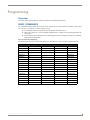
Programming ....................................................................................................39
Overview ................................................................................................................ 39
SEND_COMMANDS................................................................................................ 39
Port Functionality Mapping ........................................................................................... 39
AUDIO SEND_COMMANDs .................................................................................... 40
AI<input>O<output>................................................................................................................
?AUDIN_FORMAT_AUTO .........................................................................................................
AUDIN_FORMAT_AUTO ...........................................................................................................
?AUDOUT_ASSIGN ...................................................................................................................
?AUDOUT_FORMAT .................................................................................................................
iv
40
40
40
40
40
Instruction Manual - Solecis Digital Switchers
Table of Contents
AUDOUT_FORMAT ................................................................................................................... 40
?AUDOUT_MUTE ...................................................................................................................... 40
Video SEND_COMMANDs...................................................................................... 41
VI<input>O<output> ................................................................................................................
?VIDIN_AUTO_SELECT ..............................................................................................................
VIDIN_AUTO_SELECT................................................................................................................
AUDOUT_MUTE ........................................................................................................................
CI<input>O<output> ................................................................................................................
?VIDIN_EDID .............................................................................................................................
VIDIN_EDID ...............................................................................................................................
?VIDIN_EDID_AUTO..................................................................................................................
VIDIN_EDID_AUTO....................................................................................................................
?VIDIN_FORMAT .......................................................................................................................
?VIDIN_HDCP............................................................................................................................
VIDIN_HDCP..............................................................................................................................
?VIDIN_HSHIFT .........................................................................................................................
VIDIN_HSHIFT ...........................................................................................................................
?VIDIN_PHASE ..........................................................................................................................
VIDIN_PHASE ............................................................................................................................
?VIDIN_PREF_EDID ...................................................................................................................
VIDIN_PREF_EDID .....................................................................................................................
?VIDIN_RES_REF .......................................................................................................................
VIDIN_RES_REF .........................................................................................................................
?VIDIN_STATUS.........................................................................................................................
?VIDIN_VSHIFT..........................................................................................................................
VIDIN_VSHIFT ...........................................................................................................................
?VIDOUT_ASSIGN .....................................................................................................................
?VIDOUT_MUTE ........................................................................................................................
VIDOUT_MUTE ..........................................................................................................................
41
41
41
41
41
42
42
42
42
42
42
43
43
43
43
43
44
44
44
44
44
44
45
45
45
45
USB SEND_COMMANDs ........................................................................................ 46
?USB_HID_CONFIG ...................................................................................................................
USB_HID_CONFIG.....................................................................................................................
?USB_HID_ROUTE .....................................................................................................................
USB_HID_ROUTE.......................................................................................................................
46
46
46
46
System SEND_COMMANDs.................................................................................... 46
?FWVERSION ............................................................................................................................ 46
REBOOT .................................................................................................................................... 46
Appendix A - Telnet (Terminal) Commands ......................................................47
Establishing a Terminal Connection via Telnet........................................................ 47
Establishing a terminal connection via Telnet at the CMD prompt ............................... 47
Establishing a terminal connection via NetLinx Studio.................................................. 47
Telnet Username and Password.............................................................................. 47
Additional Notes ........................................................................................................... 47
Setting a Telnet Username and Password ..................................................................... 48
Telnet Commands ................................................................................................... 48
? or Help ................................................................................................................................... 48
DEVICE STATUS ........................................................................................................................ 48
Instruction Manual - Solecis Digital Switchers
v
Table of Contents
DIPSWITCH ...............................................................................................................................
EXIT ..........................................................................................................................................
FACTORYFWIMAGE .................................................................................................................
GET CONFIG.............................................................................................................................
GET CONNECTION...................................................................................................................
GET DEVICE..............................................................................................................................
GET DNS...................................................................................................................................
GET FRIENDLY..........................................................................................................................
GET IP .......................................................................................................................................
GET LOCATION ........................................................................................................................
GET SN .....................................................................................................................................
MSG [ON|OFF] ..........................................................................................................................
NDP UNBIND............................................................................................................................
PING [ADDRESS].......................................................................................................................
REBOOT....................................................................................................................................
RENEW DHCP ...........................................................................................................................
RESET FACTORY.......................................................................................................................
SEND_COMMAND[D:P:S,"'command'"] ...................................................................................
SEND_STRING[D:P:S,"string"] ..................................................................................................
SET CONNECTION ...................................................................................................................
SET DEVICE ..............................................................................................................................
SET DNS ...................................................................................................................................
SET ETHERNET MODE..............................................................................................................
SET FRIENDLY ..........................................................................................................................
SET IP........................................................................................................................................
SET LOCATION .........................................................................................................................
SET TELNET PORT ....................................................................................................................
SET TELNET USERNAME ..........................................................................................................
SHOW CONNECTION LOG.......................................................................................................
SHOW CONNECTION STATS....................................................................................................
SHOW LOG ...............................................................................................................................
SHOW VS100 STATS.................................................................................................................
48
48
48
49
49
49
49
50
50
50
50
50
50
50
50
50
50
51
51
51
51
51
52
52
52
52
53
53
53
53
53
53
Master Connection Modes...................................................................................... 54
Guidelines ..................................................................................................................... 54
TCP vs. UDP .................................................................................................................. 54
URL vs. NDP vs. Auto .................................................................................................... 54
Notes on Specific Telnet Clients ............................................................................. 55
Windows Client Programs ............................................................................................. 55
Linux Telnet Client......................................................................................................... 55
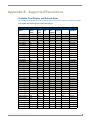
Appendix B - Supported Resolutions ................................................................57
Available Pixel Display and Refresh Rates .............................................................. 57
DVI, HDMI, and VGA Supported Input Resolutions....................................................... 57
vi
Instruction Manual - Solecis Digital Switchers
Overview
Overview
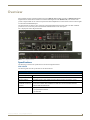
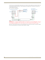
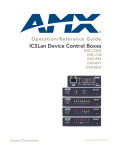
Solecis Digital Switchers include the SDX-410-DX 4x1 (FG1010-304) and SDX-810-DX 8x1 (FG1010-308) HDMI
Digital Switchers and the SDX-510M-DX 5x1 Multi-Format Digital Switcher (FG1010-315). The switchers each
provide a unique number of user connection points and include simplified local control which routes the selected signal
to both a DXLink and HDMI output.
The SDX-410-DX provides four user connection points and the SDX-810-DX provides eight. The SDX-510M-DX
provides five user connection points and includes three HDMI and two VGA video inputs.
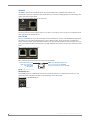
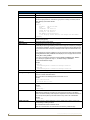
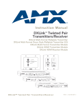
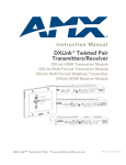
FIG. 1 displays the Solecis Digital Switchers.
FIG. 1 Solecis Digital Switchers
Specifications
The following sections list the specifications for the Solecis Digital Switchers.
SDX-410-DX
The following table lists the specifications for the SDX-410-DX:
SDX-410-DX Specifications
General:
Dimensions (HWD):
1 11/16" x 8 13/16" x 6 7/8" (43.18 mm x 223.52 mm x 175.26 mm)
Weight:
3 lb (1.4 kg)
Mounting Options:
Compatible with all V Style versatile mounting options including rack, surface, or pole
Compatible AMX Enova • Enova DGX 8/16/32/64 Digital Media Switchers
DVX/DGX and DXLink • Enova DVX-3155HD, DVX-3156HDand 2155HD All-In-One Presentation Switchers
products:
• DXLink HDMI Twisted Pair RX
Included Accessories:
• (2) 5-pin Phoenix connectors
• (1) 4-pin Phoenix connector
• (4) rubber feet
Instruction Manual - Solecis Digital Switchers
1
Overview
SDX-410-DX Specifications (Cont.)
Optional Accessories:
• AVB-VSTYLE-SURFACE-MNT, V Style Module Surface Mount (FG1010-722)
• NMX-VRK V Style Rack Shelf (FG3201-60)
• AVB-VSTYLE-POLE-MNT, V Style Module Pole Mount (FG1010-723)
• MET-6N, Metreau 6-Button Keypads with Navigation (FG5794-01-WH/BL)
• MET-7, Metreau 7-Button Keypads (FG5794-03-WH/BL)
• SP-08-AX-US, 8-Button KeyPads (US) with AxLinx (FG1311-08-SW/SB/SA)
• SP-08-AX-UK, 8-Button KeyPads (UK) with AxLinx (FG1311-08-KW/KB/KA)
• SP-08-AX-EU, 8-Button KeyPads (EU) with AxLinx (FG1311-08-EW/EB)
• HydraPort with HPX-U400-MET-6N, Metreau 6-Button Keypad Kit with Carrier
(FG554-11-BL-K)
• HydraPort with HPX-U400-MET-7 Metreau 7-Button Keypad Kit with Carrier
(FG554-13-BL-K)
• HydraPort with HPX-U400-R-MET-6N Metreau 6-Button Keypad Ramp Mount Kit
(FG564-11-BL)
• HydraPort with HPX-U400-R-MET-7 Metreau 7-Button Keypad Ramp Mount Kit
(FG564-13-BL)
• CBL-HDMI-FL, HDMI High Speed Flat Cable with RedMere Technology (FG10-2180-16)
• CBL-DP-FL, DisplayPort High Speed Flat Cable with RedMere Technology (FG10-2181-16)
• CBL-ETH-FL, Ethernet Flat Cable (FG10-2182-16)
• CBL-RGB+A-FL, RGB with Audio Flat Cable (FG10-2183-16)
• CC-USB, USB Programming Cable (FG10-5965)
Signal Transport - DXLink:
Connector:
(1) RJ-45
Supported Signal
Styles:
Digital video, audio, Ethernet, bi-directional control
Transport Layer
Throughput (Max):
10.2 Gbps
Twisted Pair Cable
Type:
Shielded Cat6, Cat6A and Cat7
DXLink twisted pair cable runs for DXLink equipment shall only be run within a common
building where a common building is defined as: the walls of the structure(s) are
physically connected and the structure(s) share a single ground reference.
For more details and helpful cabling information, reference the white paper titled Cabling for
Success with DXLink, or contact your AMX representative.
Twisted Pair Cable
Length:
Up to 328 ft. (100 m)
HDCP Support:
Yes
Active Power Requirements:
Voltage, DC (Typical):
12 VDC
Power Consumption
(Max):
18 W
Power Connector:
2-pin 3.5mm Screw Retention Connector
External, Required
Optimal performance requires use of one of the following AMX power supplies (not included):
• PSR4.4, 13.5 VDC, 4.4 A Power Supply with 3.5mm Phoenix Connector with Retention
Screws (FG423-46)
• PSN6.5, 13.5 VDC, 6.5 A Power Supply with (3) 3.5mm Phoenix Connectors (FG423-41)
Environmental:
2
Temperature
(Operating):
32° F to 104° F (0° C to 40° C)
Temperature (Storage):
-22° F to 158° F (-30° C to 70°C)
Humidity (Operating):
5% to 85% non-condensing
Humidity (Storage):
0% to 90% non-condensing
Instruction Manual - Solecis Digital Switchers
Overview
SDX-410-DX Specifications (Cont.)
Front Connectors:
Advanced
(1) USB Mini-B Connector
Configuration Interface:
ID Pushbutton:
(1) ID Pushbutton, can be used to assign the unit’s Device ID, switch between Static and
Dynamic IP addressing modes, and reset the unit to factory defaults.
Back Connectors:
HDMI Input:
(4) HDMI Type A Female Connectors
HDMI Output:
(1) HDMI Type A Female Connector
DXLink Output:
(1) RJ-45 Connector
LAN 10/100:
(2) RJ-45 Connectors
Local Power:
(1) 2-pin 3.5mm Screw Terminal Connector with Retention Screws
External Button/LED
Control Connectors:
(2) 5-pin, 3.5mm Screw Terminal Connectors
AxLink Keypad Control: (1) 4-pin, 3.5mm Screw Terminal Connector
Ethernet:
Ethernet Connections:
(2) RJ-45, 10/100 Port provides TCP/IP communication. This is an Auto MDI/MDI-X enabled
port, which allows you to use either straight-through or crossover Ethernet cables. The
Ethernet Port LEDs show communication activity, connection status, speeds, and mode
information.
Ethernet Link/Act
Indicator:
(1) Link/Activity LED (green) blinks when receiving Ethernet data packets, one on Ethernet
RJ-45 connector and one on the front panel.
Ethernet Speed
Indicator:
(1) Speed LED (yellow) lights On when the connection speed is 100 Mbps Ethernet connection
and turns OFF when the speed is 10 Mbps
Controls & Indicators:
AxLink Control Port:
(1), 4-pin 3.5 mm captive-wire connector, provides data and power to up to 2 external AxLink
Keypads
AxLink Indicator:
(1) AxLink Keypad LED (green) indicates the state of the AxLink Keypad port
LINK/ACT Indicator:
(1) LED (green), lights when the Ethernet cable is connected and an active link is established.
This LED also blinks when receiving Ethernet data packets
Status Indicator:
(1) LED (green), indicates boot and connection status
Power Indicator:
(1) Power LED (green) indicates the unit is powered on
Active Indicator:
(4) Active LEDs (green) indicate that video signal is present
HDCP Indicator:
(4) HDCP LEDs (yellow) indicate that source video is encrypted
Select Indicator:
(4) SELECT LEDs (green) indicate which video input is currently routed to the output
Integrated Switcher:
Video Switching:
4x1 (dual) audio/video switching, any of 4 inputs can be routed to the HDMI and DXLink output
simultaneously
Video Inputs:
(4) HDMI; supports HDMI/HDCP
Video Outputs:
• (1) HDMI; supports HDMI/HDCP
• (1) DXLink; supports digital video, audio, Ethernet, and bi-directional control
HDCP Support:
Yes
Select Pushbutton:
Press to manually switch the input routed to the output. Each press switches to the next input in
order, or if the last input is currently selected, switches to the first input.
HDMI:
Compatible Formats:
HDMI, HDCP, DVI
Input Signal Type
Support:
HDMI
DVI-D (Single Link with Cable Adapter)
Display Port ++ (Input Only, with HDMI Cable Adapter)
Input Connectors:
Instruction Manual - Solecis Digital Switchers
(4) HDMI Type A Female
3
Overview
SDX-410-DX Specifications (Cont.)
HDMI (Cont.):
Output Signal Type
Support:
HDMI, HDCP, DVI
Input Re-clocking
(CDR):
Yes
Deep Color Support:
Yes
Color Space Support:
RGB 4:4:4
YCbCr 4:4:4 and 4:2:2
(Input signal support for YCbCr 4:4:4 and 4:2:2, output color-space is converted to RGB 4:4:4)
3D Format Support:
Yes (HDMI Primary Formats)
Frame Packing 1080p up to 24Hz
Frame Packing 720p up to 50/60Hz
Frame Packing 1080i up to 50/60Hz
Top-Bottom 1080p up to 24Hz
Top-Bottom 720p up to 50/60Hz
Side-by-Side Half 1080p up to 50/60Hz
3D supported when the HDMI DXLink
RX Scaler is in Bypass mode and format is 1080p60 or less
Audio Format Support:
Dolby TrueHD, Dolby Digital, DTS-HD Master Audio, DTS, 2 CH through 8 CHL-PCM Dolby
Digital and DTS support up to 48kHz, 5.1 channels
Audio Resolution:
16 bit to 24 bit
Audio Sample Rate:
32 kHz, 44.1 kHz, 48 kHz, 96 kHz, 192 kHz
HDCP Support:
Yes
Supports AMX HDCP InstaGate Pro Technology
When used with an AMX Digital Media Switcher the key support is up to 16 sinks per output,
independent of source device.
When used as a single point-to-point solution the key support is defined by the source device.
4
Instruction Manual - Solecis Digital Switchers
Overview
SDX-510M-DX
The following table lists the specifications for the SDX-510M-DX:
SDX-510M-DX Specifications
General:
Dimensions (HWD):
1 11/16" x 10" x 6 7/8" (43.18 mm x 254 mm x 175.26 mm)
Weight:
3.5 lb (1.6 kg)
Mounting Options:
Compatible with V Style Module Surface Mount or V Style Rack Mount
Compatible AMX Enova • Enova DGX 8/16/32/64 Digital Media Switchers
DVX/DGX and DXLink • Enova DVX-3155HD, DVX-3156HD, and 2155HD All-In-One Presentation Switchers
products:
• DXLink HDMI Twisted Pair RX
Included Accessories:
• (2) 5-pin Phoenix connectors
• (1) 4-pin Phoenix connector
• (1) 3-pin Phoenix connector
• (4) rubber feet
• (1) universal power cord
Optional Accessories:
• AVB-VSTYLE-RMK-1U, V Style Module Tray (FG1010-720)
• NMX-VRK V Style Rack Shelf (FG3201-60)
• AVB-VSTYLE-POLE-MNT, V Style Module Pole Mount (FG1010-723)
• MET-6N, Metreau 6-Button Keypads with Navigation (FG5794-01-WH/BL)
• MET-7, Metreau 7-Button Keypads (FG5794-03-WH/BL)
• SP-08-AX-US, 8-Button KeyPads (US) with AxLinx (FG1311-08-SW/SB/SA)
• SP-08-AX-UK, 8-Button KeyPads (UK) with AxLinx (FG1311-08-KW/KB/KA)
• SP-08-AX-EU, 8-Button KeyPads (EU) with AxLinx (FG1311-08-EW/EB)
• HydraPort with HPX-U400-MET-6N, Metreau 6-Button Keypad Kit with Carrier
(FG554-11-BL-K)
• HydraPort with HPX-U400-MET-7 Metreau 7-Button Keypad Kit with Carrier
(FG554-13-BL-K)
• HydraPort with HPX-U400-R-MET-6N Metreau 6-Button Keypad Ramp Mount Kit
(FG564-11-BL)
• HydraPort with HPX-U400-R-MET-7 Metreau 7-Button Keypad Ramp Mount Kit
(FG564-13-BL)
• CBL-HDMI-FL, HDMI High Speed Flat Cable with RedMere Technology (FG10-2180-16)
• CBL-DP-FL, DisplayPort High Speed Flat Cable with RedMere Technology (FG10-2181-16)
• CBL-ETH-FL, Ethernet Flat Cable (FG10-2182-16)
• CBL-RGB+A-FL, RGB with Audio Flat Cable (FG10-2183-16)
• CC-USB, USB Programming Cable (FG10-5965)
Signal Transport - DXLink:
Connector:
(1) RJ-45
Supported Signal
Styles:
Digital video, audio, Ethernet, bi-directional control
Transport Layer
Throughput (Max):
10.2 Gbps
Twisted Pair Cable
Type:
Shielded Cat6, Cat6A and Cat7
DXLink twisted pair cable runs for DXLink equipment shall only be run within a common
building where a common building is defined as: the walls of the structure(s) are
physically connected and the structure(s) share a single ground reference.
For more details and helpful cabling information, reference the white paper titled Cabling for
Success with DXLink, or contact your AMX representative.
Twisted Pair Cable
Length:
Up to 328 ft. (100 m)
HDCP Support:
Yes
Instruction Manual - Solecis Digital Switchers
5
Overview
SDX-510M-DX Specifications (Cont.)
Active Power Requirements:
Voltage, AC (Typical):
110-240VAC, 47-63 Hz
Power Consumption
(Max):
48 W
Power Connector:
IEC Power Cord Connector 100-240 VAC 47-63 Hz
DXLink Power:
Supplies power to a DXLink Twisted Pair RX, when used in point-to-point applications
Power Supply:
Internal, Included
Yes
Environmental:
Temperature
(Operating):
32° F to 104° F (0° C to 40° C)
Temperature (Storage):
-22° F to 158° F (-30° C to 70°C)
Humidity (Operating):
5% to 85% non-condensing
Humidity (Storage):
0% to 90% non-condensing
USB (HID) Keyboard and Mouse:
USB (HID)
(1) USB Type Connector ("TO HOST"); connect a Solecis Digital Switcher with DXLink to a PC
and emulate keyboard and mouse commands from a DXLink Receiver
Front Connectors:
ID Pushbutton:
(1) ID Pushbutton, can be used to assign the unit’s Device ID, switch between Static and
Dynamic IP addressing modes, and reset the unit to factory defaults.
AxLink Keypad Control: (1) 4-pin, 3.5mm Screw Terminal Connector
Ethernet LAN OUT:
(3) RJ-45 Connectors
HDMI Output:
(1) HDMI Type A Female Connector
DXLink Output:
(1) RJ-45 Connector
USB Host Port:
(1) USB Type B Connector "TO HOST"
USB Device Port:
(1) USB Type A Connector, reserved for future use
Back Connectors:
Advanced
(1) USB Mini-B Connector
Configuration Interface:
HDMI Inputs:
(3) HDMI Type A Female Connectors
VGA Inputs:
(2) HD-15 Connectors
Single External Button/ (1) 3-pin, 3.5mm Screw Terminal Connector
LED Control Connector:
Dual External Button/
(2) 5-pin, 3.5mm Screw Terminal Connectors
LED Control Connector:
Analog Stereo Inputs:
(2) 1/8" mini-Stereo Jack
AC Power Connection:
IEC Power Cord Connector
Ethernet:
6
Ethernet Connections:
(3) RJ-45, 10/100 Port provides TCP/IP communication. This is an Auto MDI/MDI-X enabled
port, which allows you to use either straight-through or crossover Ethernet cables. The
Ethernet Port LEDs show communication activity, connection status, speeds, and mode
information.
Ethernet Link/Act
Indicator:
(1) Link/Activity LED (green) blinks when receiving Ethernet data packets, one on Ethernet
RJ-45 connector and one on the front panel.
Ethernet Speed
Indicator:
(1) Speed LED (yellow) lights On when the connection speed is 100 Mbps Ethernet connection
and turns OFF when the speed is 10 Mbps
Instruction Manual - Solecis Digital Switchers
Overview
SDX-510M-DX Specifications (Cont.)
Controls & Indicators:
AxLink Keypad Port:
(1), 4-pin 3.5 mm captive-wire connector, provides data and power to up to 2 external AxLink
Keypads
AxLink Indicator:
(1) AxLink Keypad LED (green) indicates the state of the AxLink Keypad port
LINK/ACT Indicator:
(1) LED (green), lights when the Ethernet cable is connected and an active link is established.
This LED also blinks when receiving Ethernet data packets
Status Indicator:
(1) LED (green), indicates boot and connection status
Power Indicator:
(1) Power LED (green) indicates the unit is powered on
ID Pushbutton:
(1) ID Pushbutton, can be used to assign the unit’s Device ID, switch between Static and
Dynamic IP addressing modes, and reset the unit to factory defaults.
Integrated Switcher:
Video Switching:
Video Inputs:
5x1 (dual) audio/video switching, any of 5 inputs can be routed to the HDMI and DXLink output
simultaneously
• (2) HD15; supports RGB
• (3) HDMI; supports HDMI/HDCP
Video Outputs:
• (1) HDMI; supports HDMI/HDCP
• (1) DXLink; supports digital video, audio, Ethernet, and bi-directional control
HDCP Support:
Yes
HDMI:
Compatible Formats:
HDMI, HDCP, DVI
Input Signal Type
Support:
HDMI
DVI-D (Single Link with Cable Adapter)
Display Port ++ (Input Only, with HDMI Cable Adapter)
Input Connectors:
(3) HDMI Type A Female
Output Signal Type
Support:
HDMI, HDCP, DVI
Input Re-clocking
(CDR):
Yes
Deep Color Support:
Yes
Color Space Support:
RGB 4:4:4
YCbCr 4:4:4 and 4:2:2
(Input signal support for YCbCr 4:4:4 and 4:2:2, output color-space is converted to RGB 4:4:4)
3D Format Support:
Yes (HDMI Primary Formats)
Frame Packing 1080p up to 24Hz
Frame Packing 720p up to 50/60Hz
Frame Packing 1080i up to 50/60Hz
Top-Bottom 1080p up to 24Hz
Top-Bottom 720p up to 50/60Hz
Side-by-Side Half 1080p up to 50/60Hz
3D supported when the HDMI DXLink
RX Scaler is in Bypass mode and format is 1080p60 or less
Audio Format Support:
Dolby TrueHD, Dolby Digital, DTS-HD Master Audio, DTS, 2 CH through 8 CHL-PCM Dolby
Digital and DTS support up to 48kHz, 5.1 channels
Audio Resolution:
16 bit to 24 bit
Audio Sample Rate:
32 kHz, 44.1 kHz, 48 kHz, 96 kHz, 192 kHz
Instruction Manual - Solecis Digital Switchers
7
Overview
SDX-510M-DX Specifications (Cont.)
HDMI (Cont.):
HDCP Support:
Yes
Supports AMX HDCP InstaGate Pro Technology
When used with an AMX Digital Media Switcher the key support is up to 16 sinks per output,
independent of source device.
When used as a single point-to-point solution the key support is defined by the source device.
Analog Video:
Compatible Formats:
RGBHV
Input Connector:
HD-15
Resolution Support:
up to 1920x1200@60Hz Reduce Blanking
Auto-Adjust Input:
Supported
Digital Processing:
24-bit, 165 MHz
Stereo Audio:
8
Input Signal Types:
Stereo Analog
Input Connectors:
1/8" Mini-Stereo Jack
Analog Input Level
(Max):
+2 dBu, unbalanced
Analog to Digital
Conversion
48 kHz Sample Rate, 24-bit
Analog to Digital
Reference Level
+2.5 dBu = 0 dBfs
Instruction Manual - Solecis Digital Switchers
Overview
SDX-810-DX
The following table lists the specifications for the SDX-810-DX:
SDX-810-DX Specifications
General:
Dimensions (HWD):
1 11/16" x 17" x 4 3/8" (43.18 mm x 431.8 mm x 111.25 mm)
Weight:
5.5 lb (2.5 kg)
Compatible AMX Enova • Enova DGX 8/16/32/64 Digital Media Switchers
DVX/DGX and DXLink • Enova DVX-3155HD, DVX-3156HD and 2155HD All-In-One Presentation Switchers
products:
• DXLink HDMI Twisted Pair RX
Included Accessories:
• (4) 5-pin Phoenix connectors
• (1) 4-pin Phoenix connector
• (4) rubber feet
• V-Style Surface Mounting Brackets
Optional Accessories:
• MET-6N, Metreau 6-Button Keypads with Navigation (FG5794-01-WH/BL)
• MET-7, Metreau 7-Button Keypads (FG5794-03-WH/BL)
• SP-08-AX-US, 8-Button KeyPads (US) with AxLinx (FG1311-08-SW/SB/SA)
• SP-08-AX-UK, 8-Button KeyPads (UK) with AxLinx (FG1311-08-KW/KB/KA)
• SP-08-AX-EU, 8-Button KeyPads (EU) with AxLinx (FG1311-08-EW/EB)
• HydraPort with HPX-U400-MET-6N, Metreau 6-Button Keypad Kit with Carrier
(FG554-11-BL-K)
• HydraPort with HPX-U400-MET-7 Metreau 7-Button Keypad Kit with Carrier
(FG554-13-BL-K)
• HydraPort with HPX-U400-R-MET-6N Metreau 6-Button Keypad Ramp Mount Kit
(FG564-11-BL)
• HydraPort with HPX-U400-R-MET-7 Metreau 7-Button Keypad Ramp Mount Kit
(FG564-13-BL)
• CBL-HDMI-FL, HDMI High Speed Flat Cable with RedMere Technology (FG10-2180-16)
• CBL-DP-FL, DisplayPort High Speed Flat Cable with RedMere Technology (FG10-2181-16)
• CBL-ETH-FL, Ethernet Flat Cable (FG10-2182-16)
• CBL-RGB+A-FL, RGB with Audio Flat Cable (FG10-2183-16)
• CC-USB, USB Programming Cable (FG10-5965)
Signal Transport - DXLink:
Connector:
(1) RJ-45
Supported Signal
Styles:
Digital video, audio, Ethernet, bi-directional control and power
Transport Layer
Throughput (Max):
10.2 Gbps
Twisted Pair Cable
Type:
Shielded Cat6, Cat6A and Cat7
DXLink twisted pair cable runs for DXLink equipment shall only be run within a common
building where a common building is defined as: the walls of the structure(s) are
physically connected and the structure(s) share a single ground reference.
For more details and helpful cabling information, reference the white paper titled Cabling for
Success with DXLink, or contact your AMX representative.
Active Power Requirements:
Twisted Pair Cable
Length:
Up to 328 ft. (100 m)
HDCP Support:
Yes
Voltage, DC (Typical):
12 VDC
Power Consumption
(Max):
21 W
Power Connector:
2-pin 3.5mm Screw Retention Connector
Instruction Manual - Solecis Digital Switchers
9
Overview
SDX-810-DX Specifications (Cont.)
Power Supply:
External, Required
Optimal performance requires use of one of the following AMX power supplies (not included):
• PSR4.4, 13.5 VDC, 4.4 A Power Supply with 3.5mm Phoenix Connector with Retention
Screws (FG423-46)
• PSN6.5, 13.5 VDC, 6.5 A Power Supply with (3) 3.5mm Phoenix Connectors (FG423-41)
Environmental:
Temperature
(Operating):
32° F to 104° F (0° C to 40° C)
Temperature (Storage):
-22° F to 158° F (-30° C to 70°C)
Humidity (Operating):
5% to 85% non-condensing
Humidity (Storage):
0% to 90% non-condensing
Front Connectors:
Advanced
(1) USB Mini-B Connector
Configuration Interface:
ID Pushbutton:
(1) ID Pushbutton, can be used to assign the unit’s Device ID, switch between Static and
Dynamic IP addressing modes, and reset the unit to factory defaults.
Back Connectors:
HDMI Input:
(8) HDMI Type A Female Connectors
HDMI Output:
(1) HDMI Type A Female Connector
DXLink Output:
(1) RJ-45 Connector
LAN 10/100:
(2) RJ-45 Connectors
Local Power:
(1) 2-pin 3.5mm Screw Terminal Connector with Retention Screws
External Button/LED
Control Connectors:
(4) 5-pin, 3.5mm Screw Terminal Connectors
AxLink Keypad Control: (1) 4-pin, 3.5mm Screw Terminal Connector
Ethernet:
Ethernet Connections:
(2) RJ-45, 10/100 Port provides TCP/IP communication. This is an Auto MDI/MDI-X enabled
port, which allows you to use either straight-through or crossover Ethernet cables. The Ethernet
Port LEDs show communication activity, connection status, speeds, and mode information.
Ethernet Link/Act
Indicator:
(1) Link/Activity LED (green) blinks when receiving Ethernet data packets, one on Ethernet
RJ-45 connector and one on the front panel.
Ethernet Speed
Indicator:
(1) Speed LED (yellow) lights On when the connection speed is 100 Mbps Ethernet connection
and turns OFF when the speed is 10 Mbps
Controls & Indicators:
10
AxLink Control Port:
(1), 4-pin 3.5 mm captive-wire connector, provides data and power to up to 2 external AxLink
Keypads
AxLink Indicator:
(1) AxLink Keypad LED (green) indicates the state of the AxLink Keypad port
LINK/ACT Indicator:
(1) LED (green), lights when the Ethernet cable is connected and an active link is established.
This LED also blinks when receiving Ethernet data packets
Status Indicator:
(1) LED (green), indicates boot and connection status
Power Indicator:
(1) Power LED (green) indicates the unit is powered on
Signal Indicator:
(8) Signal LEDs (green) indicate that video signal is present
HDCP Indicator:
(8) HDCP LEDs (yellow) indicate that source video is encrypted
Select Indicator:
(8) SELECT LEDs (green) indicate which video input is currently routed to the output
Instruction Manual - Solecis Digital Switchers
Overview
SDX-810-DX Specifications (Cont.)
Integrated Switcher:
Video Switching:
8x1 (dual) audio/video switching, any of 8 inputs can be routed to the HDMI and DXLink output
simultaneously
Video Inputs:
(8) HDMI; supports HDMI/HDCP
Video Outputs:
• (1) HDMI; supports HDMI/HDCP
• (1) DXLink; supports digital video, audio, Ethernet, and bi-directional control
HDCP Support:
Yes
Select Pushbutton:
Press to manually switch the input routed to the output. Each press switches to the next input in
order, or if the last input is currently selected, switches to the first input.
HDMI:
Compatible Formats:
HDMI, HDCP, DVI
Input Signal Type
Support:
HDMI
DVI-D (Single Link with Cable Adapter)
Display Port ++ (Input Only, with HDMI Cable Adapter)
Input Connectors:
(8) HDMI Type A Female
Output Signal Type
Support:
HDMI, HDCP, DVI
Input Re-clocking
(CDR):
Yes
Deep Color Support:
Yes
Color Space Support:
RGB 4:4:4
YCbCr 4:4:4 and 4:2:2
(Input signal support for YCbCr 4:4:4 and 4:2:2, output color-space is converted to RGB 4:4:4)
3D Format Support:
Yes (HDMI Primary Formats)
Frame Packing 1080p up to 24Hz
Frame Packing 720p up to 50/60Hz
Frame Packing 1080i up to 50/60Hz
Top-Bottom 1080p up to 24Hz
Top-Bottom 720p up to 50/60Hz
Side-by-Side Half 1080p up to 50/60Hz
3D supported when the HDMI DXLink
RX Scaler is in Bypass mode and format is 1080p60 or less
Audio Format Support:
Dolby TrueHD, Dolby Digital, DTS-HD Master Audio, DTS, 2 CH through 8 CHL-PCM Dolby
Digital and DTS support up to 48kHz, 5.1 channels
Audio Resolution:
16 bit to 24 bit
Audio Sample Rate:
32 kHz, 44.1 kHz, 48 kHz, 96 kHz, 192 kHz
HDCP Support:
Yes
Supports AMX HDCP InstaGate Pro Technology
When used with an AMX Digital Media Switcher the key support is up to 16 sinks per output,
independent of source device.
When used as a single point-to-point solution the key support is defined by the source device.
Instruction Manual - Solecis Digital Switchers
11
Overview
12
Instruction Manual - Solecis Digital Switchers
Device Connectors
Device Connectors
Overview
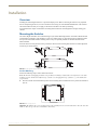
This chapter provides functional details for each item on the front and rear panel of the Solecis Digital Switchers. See the
Wiring Specifications section on page 21 for information on wiring connectors for individual ports.
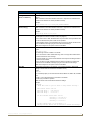
FIG. 2 displays the front panels of the SDX-410-DX, SDX-510M-DX, and SDX-810-DX:
FIG. 2 Solecis Digital Switchers front panels
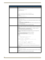
FIG. 3 displays the back panel of the SDX-410-DX, SDX-510M-DX, and SDX-810-DX:
FIG. 3 Solecis Digital Switchers back panels
Instruction Manual - Solecis Digital Switchers
13
Device Connectors
Controls and Indicators
The following sub-sections describe each component on the front panel of the switcher. Refer to FIG. 2 on page 13 for
the component layout of the front panel.
SELECT Pushbutton
Press the SELECT pushbutton to manually switch the input routed to the output. Each press switches to the next input in
order, or if the last input is currently selected, switches to the first input. The pushbutton features an POWER LED which
indicates the switcher is powered on.
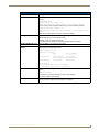
FIG. 4 displays the SELECT pushbutton.
FIG. 4 SELECT Pushbutton
LEDs
The LEDs on the front panel indicate the communications status of several different connections. All Solecis Digital
Switchers feature STATUS, LINK/ACT, and AXLINK KEYPAD LEDs. The SDX-410-DX and SDX-810-DX also
feature SELECT, HDCP, and ACTIVE LEDs for each available input on the switchers.
FIG. 5 displays the front panel LEDs on the SDX-410-DX.
FIG. 5 Front Panel - LEDs (SDX-410-DX)
The following table provides the details for each LED on the switchers:
Front Panel LEDs
Label
Color
Description
STATUS
green
Indicates the boot and connection status.
LINK/ACT
green
Indicates communication status. This LED also blinks when receiving data.
AXLINK KEYPAD
green
Blinks to indicate the status of the AxLink Keypad port (located on the rear panel
of the device.)
• Off - No power, or the switcher is not functioning properly.
• 1 blink per second - Normal operation.
• 3 blinks per second - AxLink bus error. Check all AxLink bus connections.
The following LEDs are only available on the SDX-410-DX and SDX-810-DX:
SELECT
green
HDCP
yellow
Indicates which video input is currently routed to the video output.
Indicates that the source video is encrypted.
Note: If the selected input has the HDCP disabled, all HDCP LEDs will be off. If
selected input has HDCP enabled, the inputs with protected content will have
HDCP LEDs on. See the VIDIN_HDCP section on page 43 for information about
enabling and disabling HDCP.
ACTIVE
14
green
Indicates that a video signal is present.
Instruction Manual - Solecis Digital Switchers
Device Connectors
AXLINK KEYPAD Port (4-pin captive-wire)
The AXLINK KEYPAD port allows the switcher to provide power and data to up to two AMX AxLink Keypads.
AxLink functionality requires a NetLinx Master to be present on the connected network. The AXLINK KEYPAD LED
indicating activity on the port is located on the front panel of the device. See the LEDs section on page 14 for more
information.
FIG. 6 displays the AxLink ports on the SDX-410-DX and SDX-510M-DX.
SDX-510M-DX
SDX-410-DX
FIG. 6 AxLink Ports
The AxLink port can be used to supply power to downstream AxLink-compatible devices. The port is capable of
providing at least 2 Amps of 12V power.
For information on wiring for the AxLink port, see the AXLINK KEYPAD Port section on page 25.
CONFIG DIP Switch
Use the Configuration DIP switch to enable/disable the LAN ports, set the DXLink mode, and set network connectivity.
All DIP switches are initially set to the OFF position. DIP switch settings are read on reboot. Any changes to the DIP
switch settings are not acted upon until after you reboot the device.
FIG. 7 displays the CONFIG DIP switch.
FIG. 7 CONFIG DIP switch
The DIP switches are numbered 1-4 from left to right. The following table lists the settings for each DIP switch.
DIP Switch Settings
Pin
Description
ON
1
Enable/Disable LAN 10/100
Enables all External LAN 10/100 Disables all External LAN 10/100
ports
ports
2
Set the DXLink mode
Maintains ability to read the DIP switch but takes no action. Always
responds to the ?DXLINK command as an endpoint.
3
Network Connectivity
IP for the internal processor is
enabled. This switch does not
affect the External Ethernet
ports.
IP for the internal processor is
disabled. This switch does not
affect the External Ethernet ports.
4
Not Defined
No action
No action
Instruction Manual - Solecis Digital Switchers
OFF
15
Device Connectors
ID Pushbutton
The ID Pushbutton can be used to perform f our types of initial configuration settings:
Toggle between DHCP and static IP addressing (see page 30)
Assign a device address (see page 31)
Reset the unit to its factory default settings, which affects the parameters but not the firmware version (see
page 31)
Restore the unit to its factory firmware image, which affects both the firmware version and the parameters
(see page 32)
The functions performed depend on when and for how long the ID Pushbutton is pressed and held. ID Pushbutton
functions can also be implemented using Telnet commands.
FIG. 8 displays the ID pushbutton.
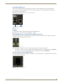
FIG. 8 ID Pushbutton
External Button/LED Control Connectors
The External Button/LED Control connectors are 5-pin, 3.5mm terminal screw connectors that you can use to connect a
single-button module such as the HPX-U100-BTN. The SDX-410-DX features two connectors, while the SDX-810-DX
features four. (The SDX-510M-DX features two sets of Dual External buttons. See the GROUP INPUTS
(SDX-510M-DX only) section on page 17 for more information.) With a single button module connected to one of these
ports, you can press the button on the module to send a button press event to a connected Master. You can use this
function to have the Master send a command back to the switcher to execute a switch.
FIG. 9 displays the External Button/LED Control Connectors on the SDX-410-DX.
FIG. 9 External Button/LED Control connectors (SDX-410-DX)
16
Instruction Manual - Solecis Digital Switchers
Device Connectors
Inputs and Outputs
The following sub-sections describe each component on the rear panel of the switchers. Refer to FIG. 3 on page 13 for
the complete layout of the rear panel.
HDMI INPUTS
The HDMI INPUT connectors on the rear panel route digital video (and audio) from connected source input devices to
the connected output devices. The SDX-410-DX features four connectors, while the SDX-810-DX features eight and the
SDX-510M-DX features three.These inputs support the following audio formats:
Dolby TrueHD
Dolby Digital
DTS-HD Master Audio™
DTS
Note: 2 CH through 8 CH L-PCM Dolby Digital and DTS support up to 48kHz, 5.1 channels.
FIG. 10 displays the HDMI INPUTS for the SDX-410-DX.
FIG. 10 HDMI INPUTS
For more information about these connectors, including wiring, see the HDMI INPUTS section on page 21.
GROUP INPUTS (SDX-510M-DX only)
The two GROUP INPUTS areas on the rear panel each feature an HDMI port, a 15-pin VGA port, a 1/8" mini-Stereo
jack, and a 5-pin 3.5mm Dual External Button/LED Control connector.
The HDMI input supports a digital audio/video source. The VGA input port supports analog video. Use the 1/8"
mini-Stereo jack for analog audio. Though these two sets of input ports support separate digital and analog video
sources, you can only select one input at a time to be sourced to the output ports.
The SDX-510M-DX has two sets of groups in which the first external button LED control connector is used to cycle
through the inputs within a particular group. On the SDX-510M-DX, HDMI INPUT 1 is always the first input on both
groups. Group 1 contains inputs 1, 2, and 3. Group 2 contains inputs 1, 4, and 5. You can route the audio/video from one
input within a group at a time.
You can cycle through the inputs in each group by clicking a single button module connected to the Dual External
button/LED Control connector for each group (see FIG. 11). For group 1, connect the single button module to contact
closure 2. For group 2, connect the single button module to contact closure 4. Connecting button modules to contact
closures 3 or 5 will not have any effect on switching within either group. Contact closures 3 and 5 are not tied to specific
inputs, but you can use them for an auxiliary button press trigger event notification which can be recognized by a
NetLinx Master for programming purposes.
Note: If there is no signal available on both the HDMI and VGA inputs in a single group, a remote button press toggles
to input 1 and the switcher displays black video with analog audio from the group.
Note: With Group Input button switching, connection to a Master is not needed. The button press results in the switcher
directly cycling through the inputs in the group.
FIG. 11 displays the GROUP INPUTS area.
Dual External button/
LED Control connector
HDMI port
FIG. 11 GROUP INPUTS area
Instruction Manual - Solecis Digital Switchers
mini-Stereo jack
VGA port
17
Device Connectors
OUTPUTS
One HDMI connector and one DXLink (RJ-45) port transport digital video, embedded audio, Ethernet, and
bi-directional control over twisted pair cable to DXLink devices or boards, including digitally transcoded analog video
signals. Both inputs support HDCP.
FIG. 12 displays the HDMI and DXLink output ports.
FIG. 12 Output ports
See the Important Twisted Pair Cabling Requirements and Recommendations section on page 25 for information about
cable requirements for the DXLink port.
LAN 10/100
The LAN 10/100 RJ-45 ports provide 10/100 Mbps TCP/IP communication. These are Auto MDI/MDI-X enabled ports,
which allow you to use either straight-through or crossover Ethernet cables. The port LEDs show communication
activity, connection status, speeds, and mode information. The SDX-410-DX and SDX-810-DX each feature two LAN
OUT ports located on the back panel of the units. The SDX-510M-DX features three LAN OUT ports located on its front
panel.
FIG. 13 displays the LAN 10/100 ports.
FIG. 13 LAN 10/100 ports
FIG. 14 describes the blink activity for the LAN OUT port and cable.
L/A - Activity LED (green)
lights when receiving or
transmitting LAN
data packets
A
L
SPD - Link LED (amber) lights when
the connection speed is 100 Mbps
and turns off when the speed in 10 Mbps.
FIG. 14 LAN connector / LEDs
PROGRAM Port
The PROGRAM port is a USB mini-B connector that connects the switcher to a communication port on a PC, and
supports the DGX Configuration Software for programming a custom VGA EDID.
FIG. 15 displays the PROGRAM port.
FIG. 15 PROGRAM port
18
Instruction Manual - Solecis Digital Switchers
Device Connectors
USB (SDX-510M-DX only)
The two type-A USB connectors on the front panel are used to connect peripheral devices to the SDX-510M-DX
(FIG. 16). You can use the type-B USB connector to connect the switcher to a PC and emulate keyboard and mouse
commands from a DXLink Receiver.
Note: The Type-A USB connectors are reserved for future use.
FIG. 16 displays the USB ports.
Type-A USB
Type-B USB
FIG. 16 USB ports
Power
This section describes the power options for the Solecis Digital Switchers.
Note: Apply power to the unit only after installation is complete.
INPUT POWER Connector (SDX-410-DX and SDX-810-DX only)
The INPUT PWR connector is a 2-pin 3.5mm screw terminal connector with retention screws. This power connector is
available on the SDX-410-DX and SDX-810-DX.
FIG. 17 INPUT PWR connector
Optimal performance requires use of one of the following AMX power supplies (not included):
PSR4.4, 13.5 VDC, 4.4 A Power Supply with 3.5mm Phoenix Connector with Retention Screws (FG423-46)
PSN6.5, 13.5 VDC, 6.5 A Power Supply with (3) 3.5mm Phoenix Connectors (FG423-41)
AC Power Connector (SDX-510M-DX only)
The SDX-510M-DX receives power through a 110-240VAC, 47-63 Hz connector. FIG. 18 displays the power switch and
connector for the SDX-510M-DX.
FIG. 18 Power Connector/Switch/Fuse
Instruction Manual - Solecis Digital Switchers
19
Device Connectors
20
Instruction Manual - Solecis Digital Switchers
Wiring Specifications
Wiring Specifications
Overview
This chapter provides the port pinouts and wiring specifications (when applicable) for each port on the front and rear
panels of the Solecis Digital Switchers.
Port Pinouts and Wiring Specifications
The following sub-sections describe the wiring for each port on the SDX switchers. Refer to the Device
Connectors section on page 13 for the component layout of the switchers.
HDMI INPUTS
The HDMI INPUT connectors on Solecis Digital Switchers are used to connect source input devices to the device. The
switcher routes digital video and audio from connected source input devices to the connected output devices. These ports
support HDMI (with 3D and Deep Color) and HDCP.
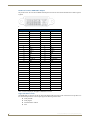
The following table describes the pinout configuration of the HDMI INPUTS connectors:
HDMI INPUT Connectors - Pinouts and Signals
Pin
Signal
Pin
Signal
1
TMDS Data 2+
11
TMDS Clock Shield
2
TMDS Data 2 Shield
12
TMDS Clock-
3
TMDS Data 2-
13
CEC
4
TMDS Data 1+
14
Reserved, HEC Data
5
TMDS Data 1 Shield
15
SCL
6
TMDS Data 1-
16
SDA
7
TMDS Data 0+
17
DDC/CEC/HEC Ground
8
TMDS Data 0 Shield
18
+5V Power (max 50mA)
9
TMDS Data 0-
19
Hot Plug Detect, HEC Data+
10
TMDS Clock+
FIG. 19 displays the pin locations for the HDMI INPUTS:
FIG. 19 HDMI pinouts
To connect HDMI input source devices (DVI and HDMI) to the HDMI INPUT connectors, the following (optional)
adapter cables are required:
DVI Input Adapter Cables
Name
Description
Length
FG#
HDMI Interface
Cable
HDMI Male to HDMI Male
6 1/2’ (2m)
FG10-2178-05
HDMI to DVI Cable
HDMI Male to DVI Male
6’ (1.828m)
FG10-2179
(See the DVI Pinout for DVI-to-HDMI Cable
Adapter section on page 22 for more information on
DVI-to-HDMI cable wiring.)
Instruction Manual - Solecis Digital Switchers
21
Wiring Specifications
DVI Pinout for DVI-to-HDMI Cable Adapter
The pinout in FIG. 20 is for DVI-to-HDMI cable adapters which can be used with the modules when a DVI-I signal is
required.
FIG. 20 DVI pinout for DVI-to-HDMI cable adapter
DVI Connector Pinout
DVI Input Pin #
Signal Name
DVI Output Pin #
Signal Name
1
Data 2-
1
Data 2-
2
Data 2+
2
Data 2+
3
GND
3
GND
4
n/c
4
n/c
5
n/c
5
n/c
6
DDC-CLK
6
DDC-CLK
7
DDC-Data
7
DDC-Data
8
n/c
8
n/c
9
Data 1-
9
Data 1-
10
Data 1+
10
Data 1+
11
GND
11
GND
12
n/c
12
n/c
13
n/c
13
n/c
14
+5 VDC In
14
+5 VDC Out*
15
GND
15
GND
16
Hot-Detect
16
Hot-Detect
17
Data 0-
17
Data 0-
18
Data 0+
18
Data 0+
19
GND
19
GND
20
n/c
20
n/c
21
n/c
21
n/c
22
GND
22
GND
23
CLK+
23
CLK+
24
CLK-
24
CLK-
C1
n/c
C1
n/c
C2
n/c
C2
n/c
C3
n/c
C3
n/c
C4
n/c
C4
n/c
C5
n/c
C5
n/c
*The +5 VDC on output pin 14 supplies a maximum of 55 mA.
Supported Audio Formats
The HDMI INPUT connectors on the rear panel route digital audio (and video) from connected source input devices to
the connected output devices. These inputs support the following audio formats:
Dolby TrueHD
Dolby Digital
DTS-HD Master Audio™
DTS
22
Instruction Manual - Solecis Digital Switchers
Wiring Specifications
VGA INPUT Ports
The SDX-510M-DX features two VGA input ports on the rear panel to route analog video from connected source input
devices to the connected output devices. These ports support standard VGA cabling.
FIG. 21 displays one of the VGA inputs.
FIG. 21 VGA INPUT 3
The VGA inputs are used to accept a variety of analog video signals from a source device. The following table provides
cable pinout details for HD-15 connections for RGBHV.
VGA Input Port Cable Pinouts
Input Pin #
VGA-RGBHV
1
Red
2
Green
3
Blue
4
n/c
5
GND
6
GND - Red
7
GND - Green
8
GND - Blue
9
+5 V DDC
10
GND
11
n/c
12
DDC_SDA
13
H Sync
14
V Sync
15
DDC_SCL
FIG. 22 displays the pinouts for the VGA inputs.
FIG. 22 VGA Input Pins
Instruction Manual - Solecis Digital Switchers
23
Wiring Specifications
DXLink OUTPUT
One DXLink (RJ-45) connector transports digital video, embedded audio, Ethernet, and bi-directional control over
twisted pair cable to DXLink devices or boards, including digitally transcoded analog video signals. The DXLink output
supports HDCP.
Note: The DXLink output on the SDX-510M-DX provides Power Over DXLink to compatible DXLink Receivers so they
do not need local power at the display or projector.
FIG. 23 displays the DXLink output.
FIG. 23 DXLINK OUTPUT
See the Important Twisted Pair Cabling Requirements and Recommendations section on page 25 for information about
cable requirements for these ports.
Twisted Pair Cable Pinouts
AMX supports both the T568A and T568B pinout specifications for termination of the twisted pair cable used between
the switcher and the DXLink receiver.
FIG. 24 displays the twisted pair pinout specifications for the DXLink input.
FIG. 24 Twisted pair cable pinouts for T568A (recommended) and T568B specifications
24
Instruction Manual - Solecis Digital Switchers
Wiring Specifications
Important Twisted Pair Cabling Requirements and Recommendations
The following requirements and recommendations apply to cabling DXLink (RJ-45) connectors:
DXLink cable runs require shielded category cable (STP) of Cat6 (or better).
DXLink twisted pair cable runs for DXLink equipment shall only be run within a common building.*
DXLink delivers 10.2 Gb/s throughput over shielded category cable. Based on this bandwidth requirement,
we recommend following industry standard practices designed for 10 Gigabit Ethernet when designing and
installing the cable infrastructure.
The cables should not be longer than necessary to reach the end-points. We recommend terminating the cable
to the actual distance required rather than leaving any excess cable in a service loop.
For more details and helpful cabling information, reference the white paper titled "Cabling for Success with DXLink"
available at www.amx.com or contact your AMX representative.
* "Common building" is defined as: Where the walls of the structure(s) are physically connected and the structure(s)
share a single ground reference.
AXLINK KEYPAD Port
The AXLINK KEYPAD port allows the switcher to provide data and power to up to two external AxLink keypads.
FIG. 25 displays the AxLink port on the SDX-410-DX.
FIG. 25 AXLINK KEYPAD Port (SDX-410-DX)
The green AXLINK KEYPAD LED indicates AxLink data activity:
Off - No power, or the switcher is not functioning properly.
1 blink per second - Normal operation.
3 blinks per second - AxLink bus error. Check all AxLink bus connections.
Note: The AXLINK KEYPAD LED is located on the front panel of the SDX-410-DX and SDX-810-DX while the AxLink
port itself is located on the rear panel. On the SDX-510M-DX, both the port and LED are located beside each other on
the front panel.
The AxLink port can be used to supply power to AxLink keypads. The port is capable of providing at least 2 Amps of
12V power up to a maximum distance of 225ft. (68.58m).
FIG. 26 provides wiring requirements for the AxLink connector:
To the switcher’s
AxLink/PWR connector
Top view
To the external AxLink device
Top view
FIG. 26 Mini-Phoenix connector wiring diagram (direct data and power)
Instruction Manual - Solecis Digital Switchers
25
Wiring Specifications
To use the 4-pin 3.5 mm mini-Phoenix (female) captive-wire connector for data communication and power transfer, the
incoming PWR and GND cable from the 12 VDC-compliant power supply must be connected to the AxLink cable
connector going to the switcher.
FIG. 27 shows the wiring diagram.
To the external AxLink device
Top view
To the switcher’s
AxLink/PWR connector
Local 12+ VDC
power supply
(coming from an
external
power supply)
Top view
FIG. 27 4-pin mini-Phoenix connector wiring diagram (using external power source)
WARNING! When you connect an external power supply, do not connect the wire from the PWR terminal (coming from
the external device) to the PWR terminal on the Phoenix connector attached to the switcher unit. Make sure to connect
only the AXM, AXP, and GND wires to the switcher’s Phoenix connector when using an external power supply.
Make sure to connect only the GND wire on the AxLink/PWR connector when using a separate 12 VDC power supply.
Do not connect the PWR wire to the AxLink connector’s PWR (+) opening.
26
Instruction Manual - Solecis Digital Switchers
Installation
Installation
Overview
Installing the Solecis Digital Switcher is a quick and simple process. Before connecting the switcher to its peripheral
devices and powering the device, be sure to mount the device using one of the methods detailed below. The switchers
also include rubber feet that you can apply to the bottom of the device for table-top mounting.
Also included in this chapter is information on making initial connections and configurations to begin running your
switcher.
Mounting the Switcher
The Solecis Digital Switchers can be mounted using V Style Surface Mounting Brackets. The Surface Mount Brackets
are designed for mounting a single module (to a wall, on or under a desk, etc.) The brackets may be attached to mount
the top or the bottom flush with the mounting surface. They are optionally available for the SDX-410-DX and the
SDX-510M-DX.
Insert the #4-40 3/16 inch pan head screws (provided) as shown in FIG. 28 and tighten. Brackets can either align flush
with the top or with the bottom.
FIG. 28 Installing Surface Mount Brackets
Surface Mounting
Perform the following steps to surface mount the switcher:
Note: The #8 x 1/2 inch tapping pan head screws provided for mounting to a flat surface are designed for wood. If the
module needs to be mounted on a different type of surface, use the appropriate type of fastener, e.g., dry wall anchors
(not provided).
1. Place the switcher in the desired final position on the mounting surface and mark the screw position as indicated in
FIG. 29.
FIG. 29 Mark screw positions
Important: The mark for the screw’s position in each of the mounting holes needs to be made in the end of the slots (all
marks to either the top of the slots or all marks to the bottom).
Instruction Manual - Solecis Digital Switchers
27
Installation
2. Set the device aside. If using the wood screws provided, drill pilot holes (drill size 29; hole diameter 0.136 in.) for
the screws 1/2 inch (1.27 cm) deep. Insert the screws in the holes, but do not tighten them completely.
FIG. 30 Pilot holes with screws
3. Align the module with the center of the double key-hole slots over the screws and slide into place as indicated in
FIG. 31.
FIG. 31 Sliding the switcher onto the Wall Mount Screws
4. Tighten the screws.
Rack Ear Brackets
Rack ear brackets are included with the SDX-810-DX. The rack ear brackets are designed for mounting a single module
(to a wall, on or under a desk, etc.) You can rotate the included brackets 90° in any direction to accommodate several
different mounting options, including tabletop, under/over the table, and vertical wall mounting.
Position and install the mounting brackets, as shown in FIG. 32, using the supplied mounting screws.
FIG. 32 Mounting the rack ears on the SDX-810-DX
28
Instruction Manual - Solecis Digital Switchers
Installation
Mounting the Switcher on a Pole
The AVB-VSTYLE-POLE-MNT, V Style Single Module Pole Mounting Kit (FG1010-723) is designed for mounting a
single module to a projector pipe (or other 2 inch diameter pipes). The kit contains all the mounting hardware for the
assembly in FIG. 33.
Perform these steps to mount the switcher on a pole:
1. Attach the mounting brackets to the module according to the instructions for surface mounting (see FIG. 28).
2. Insert the first u-bolt around the pole/pipe and through the bracket and plate according to FIG. 33.
3. Fasten securely with the hex nuts.
4. Repeat Steps 2 and 3 using the remaining u-bolt, bracket, plate, and hex nuts.
FIG. 33 Mount to projector pipe with bolts through brackets
Mounting the Switcher on a Rack Shelf
You can mount the switcher on a rack shelf by using an NMX-VRK V-Style Rack Shelf (FG3201-60). In addition to the
switcher, you can also use wire ties to mount the switcher’s power supply on the rack shelf.
FIG. 34 NMX-VRK V-Style Rack Shelf
Perform these steps to mount the encoder using the NMX-VRK Rack Shelf:
1. Invert the switcher and the rack shelf for ease of installation.
2. Attach the rack shelf to the bottom of the switcher using the #4-40 3/16 inch undercut flat head screws (provided).
Insert the screws through the underside of the rack shelf and into the holes on the bottom of the switcher. Note that
only two screws are required.
3. Install the rack shelf in a standard EIA 19 in. (48.26 cm) rack and secure with rack-mounting screws.
Instruction Manual - Solecis Digital Switchers
29
Installation
4. (This step is optional.) Attach fill plates using the #4-40 3/16 inch undercut flat head screws (provided). Be sure to
use the screw holes closest to the front of the tray.
5. Use wire ties (not provided) to mount the power supply to the rear section of the rack shelf. This step is optional.
Connections and Setup
The following sections describe how to connect your switcher to your network, audio/video sources, and accessories.
Setting the DIP Switches
Use the Configuration DIP switch to enable/disable the LAN ports and set network connectivity. All DIP switches are
initially set to the OFF position. The DIP switches are located on the front panels of the SDX-410-DX and
SDX-810-DX, and on the rear panel of the SDX-510M-DX.
Enabling the LAN 10/100 Ports on the Switcher
The LAN 10/100 ports on the switchers are disabled by default. You can enable the ports by setting #1 DIP switch to ON
(see FIG. 35).
Enabling Network Connectivity on the Switcher
Network connectivity on the switchers is disabled by default. You can enable network connectivity by setting #3 DIP
switch to ON (see FIG. 35).
#1 switch, set to ON to enable
LAN 10/100 ports
#3 switch, set to ON to enable
network connectivity
FIG. 35 Config DIP Switch (SDX-410-DX displayed)
Connecting the Switcher to a Video Output
The switchers can transmit a signal simultaneously to both DXLink and HDMI outputs.
The switcher uses standard HDMI cabling to connect to the HDMI output. Use an HDMI cable to connect the
HDMI OUT port on the rear panel of the device to the display device. (On the SDX-510M-DX, the HDMI
OUT port is located on the front panel.)
The switcher uses category cabling to connect to the DXLink output. See the Important Twisted Pair Cabling
Requirements and Recommendations section on page 25 for information about cable requirements for the
DXLink port. Use category cabling to connect the DXLINK port on the rear panel of the device to the
DXLink input port on a DXLink receiver, Enova DVX switcher, or Enova DGX switcher. (On the
SDX-510M-DX, the DXLINK POWERED port is located on the front panel.)
Applying Power
Once your have mounted the switcher, set the DIP switches, and connected the appropriate input and output devices to
the ports on the switcher, apply power by connecting the recommended power supply for your switcher. SDX-510M-DX
switchers include a universal power cord, so no external power supply is needed for that model of switcher.
The SDX-410-DX and SDX-810-DX switchers require use of one of the following AMX power supplies (not included):
PSR4.4, 13.5 VDC, 4.4 A Power Supply with 3.5mm Phoenix Connector with Retention Screws (FG423-46)
PSN6.5, 13.5 VDC, 6.5 A Power Supply with (3) 3.5mm Phoenix Connectors (FG423-41)
Toggling Between IP Addressing Modes: DHCP and Static IP
Solecis Digital Switchers support both DHCP and static IP addresses. When the #3 DIP switch is set to ON (see the
CONFIG DIP Switch section on page 15), the switchers automatically use DHCP with link-local fallback. However, you
can use a static IP address which you can set via a Telnet command (SET IP), or you can use the factory default static IP
address. The default static IP address can be recalled at any time by resetting the unit to its factory default configuration.
The default static IP address is 192.168.2.2. The default link-local address is 169.254.2.2. The switcher defaults to the
link-local address if no IP address is obtained from a DHCP server.
The ID Pushbutton can be used to toggle between the DHCP and Static IP Modes.
Perform these steps to toggle between IP addressing modes:
1. After the switcher boots, press and hold the ID Pushbutton until the STATUS and LINK/ACT LEDs toggle back
and forth in unison approximately 10 times.
30
Instruction Manual - Solecis Digital Switchers
Installation
2. Release the pushbutton when the LEDs start to blink faster.
When you release the Pushbutton, the switcher toggles either from static to dynamic (DHCP) IP addressing or
vice versa and remains in that mode until you use the ID Pushbutton to toggle the IP mode again or you
perform a factory reset.
The switcher automatically reboots to complete the process.
Assigning a Device Address (ID Mode)
You can use the ID Pushbutton in conjunction with the ID (Identify) Mode feature in NetLinx Studio. A momentary
press of the ID Pushbutton assigns a device address to the switcher (which must be bound to the Master). You must first
place the device in ID Mode in NetLinx Studio or the momentary press will be ignored.
Note: The latest version of NetLinx Studio is available to download and install from www.amx.com. Refer to the NetLinx
Studio online help for instructions on using the application.
Perform these steps to assign a device address:
1. Check to be sure DIP switch #3 on the switcher is set to ON.
2. In NetLinx Studio’s OnLine Tree, select the Master to which the switcher is bound.
3. From the Diagnostic menu, select Device Addressing. The Device Addressing dialog box opens.
4. In the ID Mode section, enter the Device and System numbers that you want assigned to the device in the
appropriate text boxes.
5. Click Start Identify Mode to place the named system in ID Mode. The button changes to “Cancel Identify Mode”
(click to cancel ID Mode). The text box below the button displays a “Waiting...Press Cancel to Quit” message.
Note: When in ID Mode, the entire system is put on hold while it waits for an event from any NetLinx device in the
named system (e.g., pressing the ID Pushbutton on the Receiver). The device that generates the first event is the device
that will be “identified.”
6. Briefly press and release the ID Pushbutton on the switcher. The switcher will exhibit the following behavior:
Respond with an ID Mode address response.
Report its old address offline.
Report its new address online.
The Online Tree will refresh to display the new device address for the switcher.
Note: NetLinx Studio (v3.3 or later) provides the ability to auto-increment IP Addresses and Hostnames as well as
Device and System Numbers. Refer to the NetLinx Studio online help for details.
Resetting the Factory Default Settings
During power up – if you hold the ID Pushbutton until the STATUS and LINK/ACT LEDs toggle back and forth in
unison approximately 10 times, then release the pushbutton when the LEDs begin to blink faster, the switcher will reset
to its factory default settings, which affect the parameters of the device, but not the firmware version.
Perform these steps to reset the factory default settings:
1. Press and hold the ID Pushbutton while plugging in the power connector. Start counting when the STATUS and
LINK/ACT LEDs begin to flash in unison, not when the power connector is inserted.
Once the switcher has started booting, both STATUS and LINK/ACT LEDs flash in unison at the rate of once
per second.
After 10 flashes at that rate, the LEDs will blink in unison at a faster rate.
Note: A press-and-hold of the ID Pushbutton at power up will prevent the switcher from attempting to come online until
the ID Pushbutton is released. The switcher will only attempt to come online if you release the Pushbutton prior to the
faster blink rate.
2. At the point that the blink rate increases, release the ID Pushbutton.
3. The switcher will automatically reboot to complete the process.
Note: Typically, after the switcher boots, the last valid input detected becomes the active input when the switcher has
Auto Select set the ENABLE. However, after a factory reset, the first input port will become active. If another signal is
detected while Auto Select is enabled, the switcher will switch to that signal.
Instruction Manual - Solecis Digital Switchers
31
Installation
Restore the Factory Firmware Image and Factory Default Parameters
During power up – if the ID Pushbutton is held until the STATUS and LINK/ACT LEDs toggle back and forth in unison
approximately 30 times (10 slow, 20 fast) and then released when they go solid, the module’s factory firmware image
will be restored. This procedure affects both the firmware version and the parameters.
Perform these steps to restore the factory firmware image and factory default parameters:
1. Press and hold the ID Pushbutton while plugging in the power connector. Start counting when the STATUS and
LINK/ACT LEDs begin to flash in unison, not when the power connector is inserted.
2. After the LEDs complete the following sequence, release the ID Pushbutton:
Once the switcher has started booting up, all LEDs flash in unison at the rate of once per second.
After 10 flashes at that rate, the LEDs will blink in unison at a faster rate.
After 10 seconds of flashing at the increased rate, all LEDs go to solid on.
3. Upon release of the ID Pushbutton, the switcher executes the following actions:
Restores itself to its factory firmware image.
Resets to factory default parameters
4. Once all actions in Step 3 are completed, the LEDs all turn off, indicating the switcher is ready to reboot.
The switcher automatically reboots to complete the process.
Factory Default Parameters
Factory Default Parameters
Parameter
Value
MAC Address
As set in factory
Serial Number
As set in factory
Ethernet Mode
Auto (i.e. speed, duplex, both, auto)
IP Addressing Mode
DHCP
IP Address (for static mode)
192.168.1.2
Netmask (for static mode)
255.255.255.0
Gateway (for static mode)
192.168.1.1
DNS1 (for static mode)
192.168.1.1
DNS2 (for static mode)
192.168.1.1
DNS3 (for static mode)
192.168.1.1
DNS Domain
amx.com
Hostname
Last 7 digits of the serial number
Master Connection Mode
NDP - see the Master Connection Modes section on page 54
Master URL (for TCP and
UDP URL modes)
"" (blank)
Master Connection Port
Number (for TCP and UDP
URL modes)
1319
Friendly-Name
"" (blank)
Note: If the Friendly Name is non-blank, both Friendly Name and Location are
concatenated to make NDPSTRING2, otherwise NDPSTRING2 is generated
from the unit’s serial number.
Location
"" (blank)
Stored MAC Address of
Master (for NDP binding)
00:00:00:00:00:00
ICSP Device Number
0 (0 = receive dynamic device number from Master)
System Number
0
Telnet Port
23
A value of 0 disables the Telnet server. Telnet is enabled by default.
32
Instruction Manual - Solecis Digital Switchers
Video Switching
Video Switching
Overview
This chapter discusses the various methods you can use to change between video inputs on your switcher. You can use
the following methods:
Auto Switching Mode
Manual Mode (Input selection via a physical button press)
Auto Switching Mode
Auto Switching mode is the default switching mode. With Auto Switching mode, the switcher responds to the most
recently added video input by switching the new input to display on the HDMI and DXLink output. If the currently
selected video source is removed, the next video port in numeric sequence with valid video is selected.
Note: If you reboot the switcher when Auto Switching is enabled, the switcher displays the last input selected before the
reboot. If you manually select an input with an invalid signal before rebooting, the same input with the invalid signal will
be displayed after the reboot.
Auto Switching mode is enabled by default. You can disable Auto Switching mode by using the
VIDIN_SELECT_AUTO command. See page 41 for more information on this command.
You can use the following NetLinx commands to select a video or audio input.
See the VI<input>O<output> command on page 41 for information on the NetLinx command you can use to
select the video input you want to use.
Use the AI<input>O<output> command on page 40 to select an audio input.
Note: These commands are only available for use with the SDX-510M-DX switcher.
Manual Mode
Manual mode involves making a video input selection by a physical button press. The Select button on the front of the
panel enables you to quickly scroll through all available inputs on the switcher. Each button press progresses the input
selection to the next numbered input. Once you reach the end of the available inputs, the next button press returns the
selection to video input position 1.
When in auto switching mode, if you press the select button, the video input remains on that position—whether there is
video established or not—until you press the Select button again, or a new video source is presented to another video
input resulting in an automatic switch to that video position.
All Cycle Contact Closure
The External Button/LED Control Connector (FIG. 35) is a contact closure matches the functionality of the Select button
when using a remote push button. It enables you to cycle through of all inputs where each press result in a move to the
next video input.
External Button/LED Control Connector
FIG. 35 External Button/LED Control Connector (SDX-510M-DX)
Group Switching (SDX-510M-DX only)
The SDX-510M-DX has two sets of groups in which the first external button LED control connector is used to cycle
through the inputs within a particular group. HDMI INPUT 1 is always the first input on both groups. Group 1 contains
inputs 1, 2, and 3. Group 2 contains inputs 1, 4, and 5. You can route the audio/video from one input within a group at a
time. You can cycle through the inputs in each group by clicking a single button module connected to the External button
connector located next to HDMI INPUT 1 on the rear panel of the device (see the External Button/LED Control
Connectors section on page 16 for more information about External button connectors.)
Note: Contact closures 3 and 5 are not tied to specific inputs, and are allowed for an auxiliary button press trigger event
notification which can be recognized by a NetLinx Master for programming purposes.
Instruction Manual - Solecis Digital Switchers
33
Video Switching
34
Instruction Manual - Solecis Digital Switchers
Upgrading Firmware
Upgrading Firmware
Overview
The basic process of upgrading firmware on Solecis Digital Switchers involves downloading the latest firmware files
from www.amx.com and using NetLinx Studio to transfer the files to a target switcher.
Use the OnLine Device tree in NetLinx Studio to view the firmware files currently loaded on the switcher. FIG. 36
shows an example OnLine Tree:
FIG. 36 NetLinx Studio - Sample Online Tree
Solecis Digital Switchers - Firmware Files
While the method of upgrading firmware files is the same for all Central switchers, there are some specific points
relative to the specific model and type of switcher that must be noted:
Upgrading the firmware on a Solecis Digital Switcher requires a firmware (*.kit) file.
The number in parenthesis is the current switcher firmware version.
Before You Start
Verify you have the latest version of the NetLinx Studio application installed on your PC. NetLinx Studio is available to
download from www.amx.com. Login to download the latest version. Alternatively, if it is already installed, use the Web
Update option in NetLinx Studio’s Help menu to obtain the latest version. The default location for the NetLinx Studio
application is Start > Programs > AMX Control Disc > NetLinx Studio > NetLinx Studio.
Verify that a LAN cable is connected from the switcher to the LAN Hub.
Verify that the switcher is powered on.
Connect to the switcher via IP address.
Establish what version of firmware is currently loaded on the switcher (see Verifying the Current Firmware
Version below).
Verifying the Current Firmware Version
Use the OnLine Tree in NetLinx Studio to verify which version of each firmware file is currently installed.
Note: These steps assume that you have already established a connection with the target switcher.
1. In NetLinx Studio, click on the OnLine Tree tab (in the Workspace Bar) to view the devices on the System.
2. Click Display and select Refresh System from the context menu. This establishes a new connection to the System
and populates the device tree with devices on that system.
3. After the Communication Verification dialog indicates active communication between the PC and the Central
switcher, verify the Central switcher and associated devices are listed in the OnLine Tree.
4. Check the appropriate product page on www.amx.com for the latest firmware files for your device.
If necessary, follow the procedures outlined in the following sections to obtain these firmware (*.kit) files from
www.amx.com and then transfer the new firmware files to the device.
Instruction Manual - Solecis Digital Switchers
35
Upgrading Firmware
Downloading the Latest Firmware Files from www.amx.com
Visit the appropriate product page at www.amx.com for the latest Solecis Digital Switcher firmware (*.kit) file for your
switcher. Firmware file links are available along the right-side of the catalog page (FIG. 37):
Firmware file
FIG. 37 Sample Switcher Firmware File Link from www.amx.com
Firmware files are bundled in a ZIP file, along with a Readme.TXT file that provides details on this firmware release.
Note: Always read the Readme.TXT file included with the firmware file for any special instructions that may be required
for an individual release.
1. Accept the AMX Licensing Agreement.
2. Download the ZIP file and unzip the contents to a known location.
Upgrading Firmware via NetLinx Studio
Note: These steps assume that you have already established a connection with the target switcher (IP connection is
preferred.)
1. In NetLinx Studio, click on the OnLine Tree tab (in the Workspace Bar) to view the devices on the System.
2. In the OnLine Tree tab, click Display and select Refresh System from the context menu. Selecting these options
establishes a new connection to the System and populates the device tree with devices on that system.
3. After the Communication Verification dialog indicates active communication between the PC and the switcher,
verify the switcher is listed in the OnLine Tree.
4. In NetLinx Studio, select Tools > Firmware Transfers > Send to NetLinx Device (FIG. 38).
The Send to NetLinx Device dialog opens.
FIG. 38 NetLinx Studio - Tools > Firmware Transfers > Send to NetLinx Device
5. Click the Browse button (...) to locate and select the firmware (*.kit) file you want to transfer, in the Browse for
Folders dialog.
Instruction Manual - Solecis Digital Switchers
36
Upgrading Firmware
The selected file is indicated in the Files area.
FIG. 39 NetLinx Studio - Send to NetLinx Device Dialog
6. Verify the target’s System number matches the value listed within the active System folder in the OnLine Tree.
The Device number is always 0 for the switcher.
Note that the Port field is disabled (FIG. 40).
FIG. 40 Send to NetLinx Device dialog (showing on-board switcher firmware upgrade
7. Verify that the Reboot Device checkbox is selected to reboot the switcher after the firmware update process is
complete (selected by default).
8. Click Send to begin the transfer. The file transfer progress is indicated in the Progress section of the dialog.
9. Click Close once the download process is complete.
Instruction Manual - Solecis Digital Switchers
37
Upgrading Firmware
10. In the OnLine Tree, right-click on the switcher and select Refresh System. This establishes a new connection and
refreshes the device list and their firmware versions in your system.
Once the process is complete, you can upgrade the remaining firmware files. All device files must be kept at compatible
firmware versions for proper operation. Therefore, all files should be used when upgrading any firmware associated with
the Integrated switchers.
Instruction Manual - Solecis Digital Switchers
38
Programming
Programming
Overview
The chapter defines all programming commands available for the SDX Digital Switchers.
SEND_COMMANDS
The commands listed in the following sections are for the switcher only. For generic NetLinx commands, see the NetLinx
Integrated Switchers WebConsole and Programming Guide.
The commands derive their input/output port addressing from the target D:P:S.
INPUT ports range from 1-10 for Audio/Video. HDMI inputs are capable of carrying both digital audio and
video signals.
Input and Output functional distinctions are disambiguated from the overlapped port numbers by combining
them with the command name.
Port Functionality Mapping
The following table lists the port functionality mapping for the audio/video ports on the Solecis Digital Switchers:
Port Functionality Mapping
Port
SDX-410-DX
SDX-510M-DX
SDX-810-DX
Address
HDMI IN 1
1
1
1
<DevID>:1:0
HDMI IN 2
2
2
2
<DevID>:2:0
HDMI IN 3
3
n/a
3
<DevID>:3:0
HDMI IN 4
4
4
4
<DevID>:4:0
HDMI IN 5
n/a
n/a
5
<DevID>:5:0
HDMI IN 6
n/a
n/a
6
<DevID>:6:0
HDMI IN 7
n/a
n/a
7
<DevID>:7:0
HDMI IN 8
n/a
n/a
8
<DevID>:8:0
HDMI OUT
1
1
1
<DevID>:1:0
DXLINK OUT
1
1
1
<DevID>:1:0
VGA IN 3
n/a
3
n/a
<DevID>:3:0
VGA IN 5
n/a
5
n/a
<DevID>:5:0
USB Device
n/a
12
n/a
<DevID>:12:0
USB Host
n/a
13
n/a
<DevID>:13:0
External Buttons 14
14
14
<DevID>:14:0
AxLink Keypad 1 15
15
15
<DevID>:15:0
AxLink Keypad 2 17
17
17
<DevID>:17:0
Instruction Manual - Solecis Digital Switchers
39
Programming
AUDIO SEND_COMMANDs
The following table lists the audio SEND_COMMANDs available for the Solecis Digital Switchers:
Audio SEND_COMMANDs
AI<input>O<output>
Switches audio input port <input> to audio output port <output>.
Note: This command is only compatible with the SDX-510M-DX. Use the
CI<input>O<output> command to switch audio on the SDX-410-DX and SDX-810-DX.
Syntax:
SEND_COMMAND "'AI<input>O<output>'"
Variables:
input = The source audio input number.
output = The audio output port number to use.
Example:
SEND_COMMAND SWITCHER,"'AI2O1'"
Switch audio input port #2 to audio output #1.
?AUDIN_FORMAT_AUTO
Requests the setting (Enabled or Disabled) for automatically detecting the audio source
format through the switcher.
Syntax:
SEND_COMMAND <DEV>, "'?AUDIN_FORMAT_AUTO'"
Example:
SEND_COMMAND AUDIO_INPUT_1, "'?AUDIN_FORMAT_AUTO'"
Returns a COMMAND string of the form: AUDIN_FORMAT_AUTO-<setting>.
AUDIN_FORMAT_AUTO
Sets the audio source format to automatically detect the audio through the switcher. This
feature is enabled by default.
Syntax:
SEND_COMMAND <DEV>, "'AUDIN_FORMAT_AUTO-<ENABLE|DISABLE>'"
Example:
SEND_COMMAND AUDIO_INPUT_1, "'AUDIN_FORMAT_AUTO-ENABLE'"
?AUDOUT_ASSIGN
Requests the audio input that is selected to go to the output.
Syntax:
SEND_COMMAND <DEV>, "'?AUDOUT_ASSIGN'"
Example:
SEND_COMMAND AUDIO_1, "'?AUDOUT_ASSIGN'"
Returns a COMMAND string of the form: AUDOUT_ASSIGN-<setting>.
?AUDOUT_FORMAT
Requests the audio output source format for the switcher.
Syntax:
SEND_COMMAND <DEV>, "'?AUDOUT_FORMAT'"
Example:
SEND_COMMAND AUDIO_OUTPUT_1, "'?AUDOUT_FORMAT'"
Returns a COMMAND string of the form: AUDOUT_FORMAT-<source>.
AUDOUT_FORMAT
Sets the audio output source format for the switcher.
Syntax:
SEND_COMMAND <DEV>, "'AUDOUT_FORMAT-<source>'"
Variable:
source = HDMI, DXLINK, or ALL
Example:
SEND_COMMAND AUDIO_OUTPUT_1, "'AUDOUT_FORMAT-HDMI'"
?AUDOUT_MUTE
Requests from the switcher which audio output is muted. The audio output is set by
AUDOUT_FORMAT.
Syntax:
SEND_COMMAND <DEV>, "'?AUDOUT_MUTE'"
Example:
SEND_COMMAND dxDev, "'?AUDOUT_MUTE'"
Returns a COMMAND string of the form: AUDOUT_MUTE-<ENABLE|DISABLE>.
40
Instruction Manual - Solecis Digital Switchers
Programming
Audio SEND_COMMANDs (Cont.)
AUDOUT_MUTE
Enable or disable audio muting on the ports specified by AUDOUT_FORMAT. The mute
state works as follows:
Setting: AUDOUT_MUTE = ENABLE
AUDOUT_FORMAT - HDMI (HDMI audio muted, DXLINK audio off)
AUDOUT_FORMAT - DXLINK (HDMI audio off, DXLINK audio muted)
AUDOUT_FORMAT - ALL (HDMI audio muted, DXLINK audio muted)
Setting: AUDOUT_MUTE = DISABLE
AUDOUT_FORMAT - HDMI (HDMI audio plays, DXLINK audio off)
AUDOUT_FORMAT - DXLINK (HDMI audio off, DXLINK audio plays)
AUDOUT_FORMAT - ALL (HDMI audio plays, DXLINK audio plays)
Syntax:
SEND_COMMAND <DEV>,"'AUDOUT_MUTE-<ENABLE|DISABLE>'"
Example:
SEND_COMMAND dxDev,"'AUDOUT_MUTE-DISABLE'"
CI<input>O<output>
Switches both the audio and video input to the output port.
Syntax:
SEND_COMMAND <DEV>, "'CI<input>O<output>'"
Variables:
input = The source input port number.
output = The output port number to use.
Examples:
SEND_COMMAND SWITCHER,"'CI2O1'"
Switches (audio/video) input port #2 to output #1.
Video SEND_COMMANDs
The following table lists the video SEND_COMMANDs available for the SDX Digital Media Switchers:
Video SEND_COMMANDs
VI<input>O<output>
Switch input to one or more outputs for switcher level Video. Set <input> to 0 to send audio
with no video.
Note: This command is only compatible with the SDX-510M-DX. Use the
CI<input>O<output> command to switch video on the SDX-410-DX and SDX-810-DX.
Syntax:
SEND_COMMAND <DEV>, "'VI<input>O<output>'"
Variables:
input = The source video input port number.
output = The video output port number to use.
Example:
SEND_COMMAND SWITCHER,"'VI2O1'"
Switch video input port #2 to video output #1.
?VIDIN_AUTO_SELECT
Requests setting for the Auto Select mode for the video input signal on the switcher.
Syntax:
SEND_COMMAND <DEV>, "'?VIDIN_AUTO_SELECT'"
Example:
SEND_COMMAND VIDEO_INPUT_1,"'?VIDIN_AUTO_SELECT'"
Returns a COMMAND string of the form: VIDIN_AUTO_SELECT-<status>.
VIDIN_AUTO_SELECT
Enables or disables the Auto Select mode for the video input signal on the switcher. This
feature is enabled by default.
Syntax:
SEND_COMMAND <DEV>,"'VIDIN_AUTO_SELECT-<ENABLE|DISABLE>'"
Example:
SEND_COMMAND VIDEO_INPUT_1,"'VIDIN_AUTO_SELECT-ENABLE'"
Instruction Manual - Solecis Digital Switchers
41
Programming
Video SEND_COMMANDs (Cont.)
?VIDIN_EDID
Requests the EDID source the video input is to be presented with.
Syntax:
SEND_COMMAND <DEV>, "'?VIDIN_EDID'"
Example:
SEND_COMMAND VIDEO_INPUT_1,"'?VIDIN_EDID'"
Returns a COMMAND string of the form: VIDIN_EDID-<source>. See the VIDIN_EDID
command for the list of potential sources.
VIDIN_EDID
Sets the EDID source to present to the video input port addressed by D:P:S.
Syntax:
SEND_COMMAND <DEV>,"'VIDIN_EDID-<source>'"
Variables:
source = All Resolutions, Mirror Out 1, Mirror Out Local, Mirror Out 1 HDMI, Mirror Out 1
DXLINK, User EDID 1, User EDID 2
Note: User EDID is only available for VGA. Mirror is only applicable to HDMI.
Example:
SEND_COMMAND VIDEO_INPUT_1,"'VIDIN_EDID-MIRROR OUT 1'"
?VIDIN_EDID_AUTO
Requests the status of the EDID update setting for the video port addressed by the D:P:S.
Syntax:
SEND_COMMAND <DEV>, "'?VIDIN_EDID_AUTO'"
Example:
SEND_COMMAND VIDEO_INPUT_1,"'?VIDIN_EDID_AUTO'"
Returns a COMMAND string of the form: VIDIN_EDID-<ENABLE|DISABLE>.
VIDIN_EDID_AUTO
Enables or disables whether the video input port addressed by D:P:S is supposed to have
its list of available resolutions for the EDID source auto detected.
Syntax:
SEND_COMMAND <DEV>,"'VIDIN_EDID_AUTO-<ENABLE|DISABLE>'"
Example:
SEND_COMMAND VIDEO_INPUT_1,"'VIDIN_EDID_AUTO-ENABLE'"
?VIDIN_FORMAT
Requests the input format of the video port addressed by the D:P:S.
Syntax:
SEND_COMMAND <DEV>, "'?VIDIN_FORMAT'"
Example:
SEND_COMMAND VIDEO_INPUT_1,"'?VIDIN_FORMAT'"
Returns a COMMAND string of the form: VIDIN_FORMAT-<HDMI|DXLINK|VGA>.
?VIDIN_HDCP
Queries the video input HDCP compliance setting of the video input port addressed by the
D:P:S.
Note: This command is only available on HDMI inputs ports on Solecis devices.
Syntax:
SEND_COMMAND <DEV>,"'?VIDIN_HDCP'"
Example:
SEND_COMMAND VIDEO_INPUT_1,"'?VIDIN_HDCP'"
Returns a string of the form: VIDIN_STATUS-<ENABLE|DISABLE>.
42
Instruction Manual - Solecis Digital Switchers
Programming
Video SEND_COMMANDs (Cont.)
VIDIN_HDCP
Sets the video input HDCP compliance setting of the video input port addressed by the
D:P:S. When VIDIN_HDCP is disabled, the addressed video input will appear to any
source as not being HDCP compliant. For computer sources that encrypt all video when
connected to an HDCP compliant display, disabling HDCP compliance on the input will
cause the computer to send non-encrypted video which can then be routed to
non-compliant displays and video conferencing systems.
Note: It may be necessary to disconnect and re-connect PC sources after changing this
setting.
WARNING! Disabling HDCP compliance for sources that do not support non-compliant
displays (such as DVD and Blu-Ray players) is not recommended and may affect Solecis
performance.
Syntax:
SEND_COMMAND <DEV>, "'VIDIN_HDCP-<option>'"
Variables:
option = ENABLE, DISABLE (default = ENABLE)
Example:
SEND_COMMAND VIDEO_INPUT_1,"'VIDIN_HDCP-ENABLE'"
Enables the HDCP compliance of video input port (#1 based on D:P:S).
Note: Only applicable on HDMI ports of Solecis switchers (not VGA inputs).
?VIDIN_HSHIFT
Requests the input Horizontal shift of the VGA video port addressed by the D:P:S.
Syntax:
SEND_COMMAND <DEV>, "'?VIDIN_HSHIFT'"
Example:
SEND_COMMAND VIDEO_INPUT_1,"'?VIDIN_HSHIFT'"
Returns a COMMAND string of the form: VIDIN_HSHIFT-<value>.
VIDIN_HSHIFT
Sets the horizontal shift of the video port addressed by the D:P:S to <value>.
Note: This command is only valid for VGA inputs.
Syntax:
SEND_COMMAND <DEV>, "'VIDIN_HSHIFT-<value>'"
Variables:
value = -50..50
Example:
SEND_COMMAND "'VIDIN_HSHIFT-2'"
Sets the Horizontal shifting of the video input port (#1 based on D:P:S) to 2 (shift to right).
SEND_COMMAND "'VIDIN_HSHIFT--3'"
Sets the horizontal shifting of the video input port (#1 based on D:P:S) to -3 (shift to left).
?VIDIN_PHASE
Requests the input phase of the video port addressed by the D:P:S. This command is valid
only for inputs whose format is set to VGA.
Syntax:
SEND_COMMAND <DEV>, "'?VIDIN_PHASE'"
Example:
SEND_COMMAND VIDEO_INPUT_1,"'?VIDIN_PHASE'"
Returns a COMMAND string of the form: VIDIN_PHASE-<value>.
Instruction Manual - Solecis Digital Switchers
43
Programming
VIDIN_PHASE
Sets the input phase of the video port addressed by the D:P:S to <value>. This command
is valid only for inputs whose format is set to VGA.
Syntax:
SEND_COMMAND <DEV>, "'VIDIN_PHASE-<value>'"
Variables:
value = 0..31
Example:
SEND_COMMAND VIDEO_INPUT_1,"'VIDIN_PHASE-23'"
Sets the phase of video input port to 23.
Video SEND_COMMANDs (Cont.)
?VIDIN_PREF_EDID
Requests the preferred resolution of the EDID source for the VGA video input. This
command only applies you select All Resolutions with the VIDIN_EDID command.
Syntax:
SEND_COMMAND <DEV>, "'?VIDIN_PREF_EDID'"
Example:
SEND_COMMAND VIDEO_INPUT_1,"'?VIDIN_PREF_EDID'"
Returns a COMMAND string of the form: VIDIN_PREF_EDID-<resolution, refresh>.
VIDIN_PREF_EDID
Sets the preferred resolution of the EDID source for the VGA video input.
This command only applies you select All Resolutions with the VIDIN_EDID command.
Syntax:
SEND_COMMAND <DEV>,"'VIDIN_PREF_EDID-<resolution, refresh>'"
Variables:
resolution, refresh = for supported input resolutions and refresh rates, see the tables
starting on page 57
Example:
SEND_COMMAND VIDEO_INPUT_1,"'VIDIN_PREF_EDID-1920x1080p,60'"
?VIDIN_RES_REF
Requests the resolution of the video input port addressed by the D:P:S.
Syntax:
SEND_COMMAND <DEV>, "'?VIDIN_RES_REF'"
Example:
SEND_COMMAND VIDEO_INPUT_1,"'?VIDIN_RES_REF'"
Returns a COMMAND string of the form: VIDIN_RES_REF-<h>x<v>,<rate>.
VIDIN_RES_REF
Sets the resolution and refresh rate of the video input port addressed by D:P:S. Invalid
combinations are ignored by the SWITCHER.
Syntax:
SEND_COMMAND <DEV>,"'VIDIN_RES_REF-<horizontal>x<vertical>,<refreshrate>'"
Variables:
horizontal = An integer value representing the horizontal.
vertical = An integer value representing the vertical. May have an additional qualifier
such as 'i' or 'p'.
refresh-rate = An integer value representing the refresh rate.
Example:
SEND_COMMAND VIDEO_INPUT_1,"'VIDIN_RES_REF-1920x1080,60'"
For a list of supported resolutions, see the Appendix B - Supported Resolutions on
page 57.
44
Instruction Manual - Solecis Digital Switchers
Programming
?VIDIN_STATUS
Requests the video input status of the video input port addressed by the D:P:S
Syntax:
SEND_COMMAND <DEV>,"'?VIDIN_STATUS'"
Example:
SEND_COMMAND VIDEO_INPUT_1,"'?VIDIN_STATUS'"
Returns a COMMAND string of the form: VIDIN_STATUS-<status string>
status string = NO SIGNAL, UNKNOWN SIGNAL, or VALID SIGNAL.
?VIDIN_VSHIFT
Requests the input Vertical shifting of the RGB video port addressed by the D:P:S. This
command is only available on VGA inputs.
Syntax:
SEND_COMMAND <DEV>, "'?VIDIN_VSHIFT'"
Example:
SEND_COMMAND VIDEO_INPUT_1,"'?VIDIN_VSHIFT'"
Returns a COMMAND string of the form: VIDIN_VSHIFT-<value>.
Video SEND_COMMANDs (Cont.)
VIDIN_VSHIFT
Sets the vertical shift of the video port addressed by the D:P:S to <value>. This command
is only available on VGA inputs.
Syntax:
SEND_COMMAND <DEV>, "'VIDIN_VSHIFT-<value>'"
Variables:
value = -10..10
Example:
SEND_COMMAND "'VIDIN_VSHIFT-2'"
Sets the vertical shifting of the video input port to 2 (shift upward).
SEND_COMMAND "'VIDIN_VSHIFT--3'"
Sets the vertical shifting of the video input port to -3 (shift downward).
?VIDOUT_ASSIGN
Requests the video input that is selected to go to the output.
Syntax:
SEND_COMMAND <DEV>, "'?VIDOUT_ASSIGN'"
Example:
SEND_COMMAND AUDIO_1, "'?VIUDOUT_ASSIGN'"
Returns a COMMAND string of the form: VIDOUT_ASSIGN-<setting>.
?VIDOUT_MUTE
Requests to see if VIDEO mute is enabled or disabled.
Syntax:
SEND_COMMAND <DEV>, "'?VIDOUT_MUTE'"
Example:
SEND_COMMAND SWITCHER,"'?VIDOUT_MUTE'"
Returns a COMMAND string of the form: VIDOUT_MUTE<ENABLE|DISABLE>
VIDOUT_MUTE
Enables or disables VIDEO mute.
Syntax:
SEND_COMMAND <DEV>,"'VIDOUT_MUTE-<setting>'"
Variable:
setting = desired mute state (ENABLE, DISABLE ENABLE-HDMI, DISABLE-HDMI,
ENABLE-DXLINK, DISABLE-DXLINK)
Example:
SEND_COMMAND SWITCHER,"'VIDOUT_MUTE-ENABLE'"
Instruction Manual - Solecis Digital Switchers
45
Programming
USB SEND_COMMANDs
The following table lists the USB SEND_COMMANDs available for the Solecis Digital Switchers:
USB SEND_COMMANDs
?USB_HID_CONFIG
Requests the current state of USB_HID pass through on the system.
Syntax:
SEND_COMMAND <DEV>, "'?USB_HID_CONFIG'"
Example:
SEND_COMMAND SWITCHER,"'?USB_HID_CONFIG'"
Returns a COMMAND string of the form: USB_HID_CONFIG-<ENABLE|DISABLE>.
USB_HID_CONFIG
Enables or disables the USB_HID pass through.
Syntax:
SEND_COMMAND <DEV>,"'USB_HID_CONFIG-<DEVICE or NONE>'"
’DEVICE’ enables pass through. ’NONE’ disables it.
Example:
SEND_COMMAND SWITCHER,"'USB_HID_CONFIG-DEVICE'"
Note: You must reboot the transmitter for the transmitter to recognize the USB device.
?USB_HID_ROUTE
Requests the IP address or hostname of the transmitter serving keyboard/mouse data to
the connected host.
Syntax:
SEND_COMMAND <DEV>, "'?USB_HID_ROUTE'"
Example:
SEND_COMMAND SWITCHER,"'?USB_HID_ROUTE'"
Returns a COMMAND string of the form: USB_HID_ROUTE-<IP ADDRESS>.
USB_HID_ROUTE
Sets the IP address or hostname of the transmitter serving keyboard/mouse data to the
connected host.
Note: When you specify a hostname, you can use a maximum of 50 characters.
Syntax:
SEND_COMMAND <DEV>, "'USB_HID_ROUTE-<IP ADDRESS>'"
Note: An IP address of 0 indicates no connection.
Example:
SEND_COMMAND SWITCHER,"'USB_HID_ROUTE-192.168.1.5'"
System SEND_COMMANDs
The following table lists the System SEND_COMMANDs available for the Solecis Digital Switchers:
System SEND_COMMANDs
46
Instruction Manual - Solecis Digital Switchers
Programming
?FWVERSION
Requests the firmware version of the switcher.
Syntax:
SEND_COMMAND <DEV>, "'?FWVERSION'"
Example:
SEND_COMMAND SWITCHER,"'?FWVERSION'"
Returns a COMMAND string of the form: FWVERSION-<version>.
REBOOT
Reboots the device.
Syntax:
SEND_COMMAND DEVICE_1,"'REBOOT'"
Instruction Manual - Solecis Digital Switchers
47
Programming
48
Instruction Manual - Solecis Digital Switchers
Appendix A - Telnet (Terminal) Commands
Appendix A - Telnet (Terminal) Commands
Establishing a Terminal Connection via Telnet
Telnet terminal communication is accessed remotely via TCP/IP. The Transmitter must have its own TCP/IP
address for a Telnet connection. The connection can be started from the Windows taskbar or in NetLinx Studio.
By default, a User Name and Password are not applied to the Telnet port (Port 23). Therefore, the port does not require
login credentials.
Establishing a terminal connection via Telnet at the CMD prompt
Perform these steps to establish a terminal connection via Telnet at the CMD prompt:
1. From your Windows Taskbar (at the far left), select Start > Run to open the Run dialog box.
2. Type cmd in the Open field.
3. Click OK to open an instance of the Windows command interpreter (cmd.exe).
4. At the prompt (>), type telnet followed by a space and the switcher’s IP address.
Example:
>telnet XXX.XXX.XXX.XXX
A Telnet session opens for the Transmitter and the welcome banner appears.*
5. At the prompt, type the Telnet command (see the table starting on page 48) and press Enter.
* If you are using Windows 7 and receive an error message, you may need to enable Telnet by completing the following:
(1) go to Start > Control Panel > Programs and Features, (2) on the left, select Turn Windows features on or off, (3)
select the Telnet Client and Telnet Server check-boxes, and (4) click OK.
Establishing a terminal connection via NetLinx Studio
Perform these steps to establish a terminal connection via NetLinx Studio:
1. In the Online Tree, select the switcher and right-click to access the short-cut menu.
2. Select Launch Telnet Window via NetLinx Studio. The Telnet window opens and the welcome banner appears.
3. At the prompt (>), type the Telnet command and press Enter.
Telnet Username and Password
The following commands are used to set the Telnet username and password for a Telnet connection:
Set Telnet Username
Set Telnet Password
By default, both the username and password are blank (empty strings). Performing a factory reset on the device with the
Pushbutton will return these values to that default.
Username – Setting the Username will have no effect if the password remains blank (empty string). That is,
defining the username alone will not result in Telnet prompting for a user login.
Password – Setting the Password will cause Telnet to prompt for a user login, whether the username has been
defined or not. If the username has been defined, this value must be entered. However, since the password
can be set independently of the username, it’s possible to have a password defined, but the username still at
its default (blank, empty string). In this case do not enter anything for the username when prompted. Simply
press Enter, which will then present the password prompt. Here, the defined password must be entered in
order to successfully open the Telnet session.
Additional Notes
Both the Telnet username and password are case-sensitive.
Three consecutive, unsuccessful attempts to log in to Telnet will cause the Telnet window to close.
Re-launching Telnet will again present the login prompt, with a fresh “batch” of login attempts.
If a Telnet login fails because of an incorrect username, an “Invalid Password” message will appear (as
opposed to an “Invalid Username” message).
The username and password are saved after reboot or power cycle.
The username and password are deleted/removed after a factory reset.
Instruction Manual - Solecis Digital Switchers
47
Appendix A - Telnet (Terminal) Commands
Setting a Telnet Username and Password
Perform these steps to set a Telnet username and password:
1. Establish a terminal connection via Telnet.
2. Type Set Telnet Username, and press Enter.
The program will prompt you to enter a new Telnet username; enter a username and press Enter.
The program will indicate that the username is being stored.
3. Type Set Telnet Password, and press Enter.
The program will prompt you to enter a password; press Enter twice to clear both the Telnet username and
password.
Enter a password and press Enter.
The program will prompt you to re-enter the password; re-enter the password and press Enter.
The program will indicate that the password is being stored.
Telnet Commands
The Telnet commands listed in the table below can be sent directly to the switcher via a Telnet terminal session.
The default Telnet port is 23. A value of 0 (zero) disables the Telnet server.
Telnet is enabled by default.
In the terminal program, type Help or a question mark (?) and press Enter to access the Help Menu and display the
terminal commands described in the table below.
Telnet Commands
Command
Description
? or Help
Display the commands listed in this table.
DEVICE STATUS
Displays device status of a specified device, port, system (<D:P:S>).
Note: Devices other than the switcher itself will be ignored.
Example:
>device status 32002:1:0
Device Status
------------Device 1123 AMX LLC, SDX-510M-DX, v99.86.00 contains 17 Ports
Port 1 - Channels:255 Levels:0
MaxStringLen=64 Types=8 bit MaxCommandLen=64 Types=8 bit
The following output channels are on:None
>
DIPSWITCH
Displays the current value for each of the DIP switch’s four toggles.
Example:
>dipswitch
Dipswitch - ON OFF OFF OFF
>
48
EXIT
Exit the Telnet session.
FACTORYFWIMAGE
Resets unit to factory firmware image and reboots the switcher.
Instruction Manual - Solecis Digital Switchers
Appendix A - Telnet (Terminal) Commands
Telnet Commands (Cont.)
Command
Description
GET CONFIG
Displays the current connection settings.
Example:
>get config
Device number: 7010
Connection Settings
-------------------------------Mode:
NDP
System Number:
2155
Master IP/URL:
192.168.43.83
Master Port:
1319
Username:
Password:
IP Settings
-------------------------------HostName:
SDX-510-000-EXB
Type:
DHCP
IP Address:
192.168.43.63
Subnet Mask:
255.255.255.0
Gateway IP:
192.168.43.2
MAC Address:
00:60:9f:99:26:f1
DHCP Server
:
Lease Origin
:
Lease Duration
:
Lease Renew (T1):
Lease Rebind (T2):
192.168.43.2
THU 01/09/2031
SUN 01/12/2031
SAT 01/11/2031
SUN 01/12/2031
12:59:02
12:59:02 (259200 sec)
00:59:02 (129600 sec)
03:59:02 (226800 sec
DNS Servers
-------------------------------Domain suffix:
amx.internal
Entry 1:
192.168.40.7
Entry 2:
192.168.40.8
Note: The system number and IP addressing information displayed is reflective of actual
operating values, not stored parameters.
GET CONNECTION
Shows the Master connection information.
Example:
>get connection
Connection Settings
-----------------------------Mode:
UDP URL
System Number:
1
Master IP/URL:
192.168.44.53
Master Port:
1319
Username:
Password:
GET DEVICE
Displays the device number.
GET DNS
Gets the list of DNS entries.
Example:
>get dns
DNS Servers
------------------------------Domain suffix: amx.internal
Entry 1:
192.168.40.7
Entry 2:
192.168.40.8
Note: When the switcher is in DHCP Mode, these are active values, NOT the stored
values that only apply to Static IP Mode.
Instruction Manual - Solecis Digital Switchers
49
Appendix A - Telnet (Terminal) Commands
Telnet Commands (Cont.)
Command
Description
GET FRIENDLY
Displays the device’s friendly name (for NDP).
GET IP
Displays the IP configuration of a device.
The device displays its D:P:S, Host Name, Type (DHCP or Static), IP Address, Subnet
Mask, Gateway IP, and MAC Address.
Example:
>GET IP
HostName
SDX-510-000-EXB
Type
DHCP
IP Address 192.168.43.63
Subnet Mask 255.255.255.0
Gateway IP 192.168.43.2
MAC Address 00:60:9f:99:26:f1
[[also displays “Lease” details; see example for GET CONFIG
command]]
GET LOCATION
Displays the location parameter for NDP, which is set by using the SET LOCATION
command (see page 52).
GET SN
Returns the device’s serial number.
MSG [ON|OFF]
Enables/Disables extended diagnostic messages.
• MSG ON [error|warning|info|debug] sets the terminal program to display log messages
generated by the Master. The level of log printed to the terminal window depends both
on the level used when sending the message and the output level selected with “msg
on.”
For example if log output is enabled via “msg on warning” then logs produced at levels
AMX_ERROR and AMX_WARNING will be displayed, but not logs produced at levels
AMX_INFO or AMX_DEBUG.
The order of severity from highest to lowest is ERROR, WARNING, INFO, DEBUG.
If no severity is supplied with “msg on,” the default setting is WARNING.
• MSG OFF disables the display.
Example:
> MSG ON
Extended diagnostic information messages turned on.
> MSG OFF
Extended diagnostic information messages turned off.
NDP UNBIND
Clears the NDP binding to a Master (takes effect after next boot).
PING [ADDRESS]
Pings an address (IP or URL), to test network connectivity to and confirms the
presence of another networked device.
The syntax matches the PING application in Windows or Linux.
Example:
>ping 192.168.29.209
192.168.29.209 is alive.
REBOOT
Reboots the switcher.
Example:
>REBOOT
Rebooting...
RENEW DHCP
Renews/releases the current DHCP lease for the switcher.
Note: Because sending this command can result in the unit acquiring a new DHCP
address and the functionality of the endpoints is dependent on the mated IP addresses of
the TX (host) and RX (device), the USB connection may need to be re-established.
Example:
>RENEW DHCP
RESET FACTORY
Resets the device’s stored parameters to factory default state including removal of all
security settings, resetting to DHCP.
This command will cause an automatic reboot.
Note: This command does not reset the device to the factory software image.
50
Instruction Manual - Solecis Digital Switchers
Appendix A - Telnet (Terminal) Commands
Telnet Commands (Cont.)
Command
Description
SEND_COMMAND
[D:P:S,"'command'"]
Sends the specified SEND_COMMAND (does not work with queries) to the current
switcher.
Note: Commands cannot be forwarded to other D:P:S. Asynchronous notifications are
available for the switchers via Telnet (and NetLinx Studio).
Example:
send_command 6501:1:0,"’VIDIN_AUTO_SELECT-ENABLE’"
SEND_STRING
[D:P:S,"string"]
Sends the specified SEND_STRING to the current switcher or connected Master.
Note: Commands cannot be forwarded to other D:P:S. Asynchronous notifications are
available for the switchers via Telnet (and NetLinx Studio).
Example:
send_string 32001:1:1,"27,18,0"
SET CONNECTION
Sets the Master connection settings interactively, allowing the user to specify the mode
(for descriptions of various connection modes, see page 54).
• If the mode is TCP or UDP, the Master URL and port number can be specified as well.
• If Auto is selected, the System number can be specified.
• After all data is entered, if the parameters have changed, the switcher will disconnect
from the Master, and begin trying to connect with the new settings.
Note: These changes do not require a reboot to take effect.
SET DEVICE
Sets the device number, and stores it in non-volatile memory.
Syntax:
SET DEVICE <num>
The valid range of device numbers is 0 to 31999.
• If the user enters a number outside that range, then no change will be made and the
switcher will issue an error message.
• A Device Number of ‘0’ means that the switcher will accept the auto-assigned device
number from the Master.
• If the new device number is different from the old device number, the switcher will
disconnect from the Master, and begin trying to connect with the new settings.
Note: These changes do not require a reboot to take effect.
SET DNS
Sets the DNS configuration of the switcher, only as applied to Static IP Mode (DNS
settings in DHCP Mode are received from the DHCP server).
Syntax:
SET DNS
This command prompts you to enter a Domain Name, DNS IP #1, DNS IP #2, and DNS
IP #3.
• Enter Y (yes) to approve/store the information in the Master.
• Enter N (no) cancels the operation.
Note: The device must be rebooted to enable new settings.
Example:
>SET DNS
-- Enter New Values or just hit Enter to keep current settings -Enter
Enter
Enter
Enter
Domain Suffix:
DNS Entry 1 :
DNS Entry 2 :
DNS Entry 3 :
amx.com
192.168.20.5
12.18.110.8
12.18.110.7
You have entered: Domain Name: amx.com
DNS Entry 1: 192.168.20.5
DNS Entry 2: 12.18.110.8
DNS Entry 3: 12.18.110.7
Is this correct? Type Y or N and Enter -> Y
Settings written. Device must be rebooted to enable new settings
Instruction Manual - Solecis Digital Switchers
51
Appendix A - Telnet (Terminal) Commands
Telnet Commands (Cont.)
Command
Description
SET ETHERNET MODE
This command sets the current LAN configuration settings per new mode.
Syntax:
SET ETHERNET MODE <newmode>
Values for newmode are:
auto
Or
10 full, 100 full, 10 half, or 100 half
Note: This command requires a reboot to enable new settings.
Examples:
set ethernet mode auto
set ethernet mode 100 full
SET FRIENDLY
Set the device’s friendly name for NDP to <name>.
Syntax:
SET FRIENDLY <name>
• Maximum length = 25 characters. If the name entered exceeds 25 characters, it will be
truncated.
• The value is stored in non-volatile memory.
• If no value specified, an automatic name consisting of AMX, the product name, and
serial number will be used.
Note: This command requires a reboot to enable new settings.
SET IP
Sets the IP configuration of a specified device.
Enter a Host Name, Type (DHCP or Fixed), IP Address, Subnet Mask, and Gateway IP
Address.
Important: Host Names may only contain ASCII letters “a” through “z” (not casesensitive), digits “0” through “9”, and the hyphen (“-”).
Note: Note: DHCP implies “DHCP with link-local fallback”.
Note: Note: For NetLinx Masters, the Host Name can only consist of alphanumeric
characters.
• Enter Y (yes) to approve/store the information on the Master.
• Enter N (no) to cancel the operation.
Note: This command requires a reboot to enable new settings.
Example:
>SET IP
--- Enter New Values or just hit Enter
to keep current settings --Enter Host Name:
DXL-RX-36d0110
Enter IP type. Type D for DHCP or S for Static IP and
then Enter:
DHCP
You have entered: Host Name
DXL-RX-36d0110
Type
DHCP
Is this correct? Type Y or N and Enter -> y
Settings written. Device must be rebooted to enable
new settings.
Note: The switcher can also be set to Static IP or DHCP Mode via the front panel ID
Pushbutton.
SET LOCATION
Sets the location parameter for NDP.
Syntax:
SET LOCATION <location>
Maximum length = 25 characters. If the name entered exceeds 25 characters, it will be
truncated.
Note: This command requires a reboot to enable new settings.
52
Instruction Manual - Solecis Digital Switchers
Appendix A - Telnet (Terminal) Commands
Telnet Commands (Cont.)
Command
Description
SET TELNET PORT
Sets the device’s IP port listened to for Telnet connections.
Example:
>SET TELNET PORT
Current telnet port number = 23
Enter new telnet port number (Usually 23)(0 = disable Telnet):
Once you enter a value and press the Enter key, you get the following message:
Setting telnet port number to 23
New telnet port number set, reboot the device for the change to take
effect.
Note: This command requires a reboot to enable new settings.
SET TELNET USERNAME
Note: This command is supported but is not presently in the Help file list of commands.
Sets the Username for a secure Telnet session.
• Default = blank (no username required)
• For details, see the Telnet Username and Password section on page 47.
SHOW CONNECTION LOG
Shows the Master connection log for the device.
SHOW CONNECTION
STATS
Shows the connection statistics for the device.
Output similar to the following example:
>show connection stats
Connection Statistics
Total
=====
ICSP Messages:
10039 received
10038 transmitted
Blink Messages:
5014 received
Last 15 Minutes
===============
333 received
333 transmitted
166 received
IP Statistics:
RX packets:29298 errors:0 discarded:0
TX packets:15286 errors:0 discarded:0
SHOW LOG
Displays the message log.
Syntax:
SHOW LOG <start>
• Use <start> to specify the message number to start displaying.
• Use <all> to display all messages.
SHOW VS100 STATS
Instruction Manual - Solecis Digital Switchers
When sent to the Solecis switcher, this command retrieves the DXLink quality information
from the receiver (or switcher input) to which it is connected.
53
Appendix A - Telnet (Terminal) Commands
Master Connection Modes
The mode of communication used for connection to the Master is specified via the SET CONNECTION Telnet
command (see page 51).
Connection mode setting options are AUTO, TCP URL, UDP URL, or NDP (default) as described:
AUTO – This mode utilizes TCP communication. It looks for a matching System Number and attempts to
come online with the first Master it sees with that System Number.
TCP URL – TCP; the Master is specified via URL.
UDP URL – UDP; the Master is specified via URL.
NDP – UDP; this mode utilizes the NDP binding process to assign the switcher (the physical device) to
a Master (or Virtual Master) via NetLinx Studio. Once bound, communications are conducted via UDP.
Note: In URL modes, the Master can use either an IP address or a DNS name.
Guidelines
UDP mode is recommended for the following types of installations:
Small-to-medium residential and corporate installations on a single subnet
Segmented control network installations (control network is a separate switching domain and subnet from
other network equipment)
Installations with the total number of NetLinx / ICSNET devices on a single Master exceeding 128
TCP mode is recommended for installations where (a) the switching domain of the network is subject to “bursty” traffic
or heavy streaming activity (>20 Mbps consumption by streaming) and where (b) the total number of NetLinx / ICSNET
devices on a single Master is less than 128.
TCP vs. UDP
TCP – Protocol has a built-in retry mechanism.
UDP – Protocol does not have a built-in retry mechanism, but consumes fewer resources on the Master.
AMX’s UDP implementation of NetLinx employs a retry mechanism to provide the reliability of TCP
with the resource efficiency of UDP.
URL vs. NDP vs. Auto
Determining which connection method to use for Master Connection Mode is essentially a matter of deciding
what information the device should use to identify the correct Master to connect to.
The default mode is NDP; the mode can be changed via the SET CONNECTION Telnet command (see page 51).
URL – The device connects to the Master with the specified URL. The device must be configured with
the URL of a specific Master via the SET CONNECTION Telnet command (see page 51).
NDP – The device connects to the Master it’s been bound to, which is based on the Master’s MAC address.
The binding is configured via NetLinx Studio. Once bound, the device must be unbound using either NetLinx
Studio or the Telnet NDP UNBIND command before being re-bound to a different Master. Alternatively,
NDP devices can be bound/unbound via options on the Master’s Web Configuration pages (System >
Manage NetLinx). For details, refer to the WebConsole & Programming Guide – NX-Series Controllers
(System - Manage NetLinx section).
Auto – The device connects to the first Master it finds with the specified System Number. The device must be
configured with the desired system number via the SET CONNECTION Telnet command (see page 51). Use
of this method requires that only one Master has any particular system number and is visible to the subnet. If
this is the case, then Auto is the simplest choice. However, with Auto, you are not hard-bound to a particular
Master. Therefore, if at some point in the future, another Master is configured with the same system number,
the result is that the switcher could show up on that other Master.
54
Instruction Manual - Solecis Digital Switchers
Appendix A - Telnet (Terminal) Commands
Notes on Specific Telnet Clients
Telnet and terminal clients exhibit different behaviors in some situations. This section states some of the known
anomalies.
Windows Client Programs
Anomalies occur when using a Windows® client if you are not typing standard ASCII characters (i.e., using the keypad
and the Alt key to enter decimal codes). Most programs will allow you to enter specific decimal codes by holding Alt
and using keypad numbers.
For example, hold Alt, hit the keypad 1, then hit keypad 0, then release Alt. The standard line feed code is entered
(decimal 10). Windows will perform an ANSI to OEM conversion on some codes entered this way because of the way
Windows handles languages and code pages.
The following codes are known to be altered, but others may be affected depending on the computer’s setup.
Characters 15, 21, 22, and any characters above 127.
This affects both Windows Telnet and Terminal programs.
Linux Telnet Client
The Linux Telnet client has three anomalies that are known at this time:
A null (\00) character is sent after a carriage return.
If an “Alt 255” is entered, two of the “255” characters are sent (per the Telnet RAFT).
If the code to return to Command mode is entered (Alt 29 which is ^]), the character is not sent, but the Telnet
Command Mode is entered.
Instruction Manual - Solecis Digital Switchers
55
Appendix A - Telnet (Terminal) Commands
56
Instruction Manual - Solecis Digital Switchers
Appendix B - Supported Resolutions
Appendix B - Supported Resolutions
Available Pixel Display and Refresh Rates
The available pixel display and refresh rates for the input devices connected to the switcher are listed in this appendix.
DVI, HDMI, and VGA Supported Input Resolutions
DVI, HDMI, and VGA Supported Input Resolutions
VGA
Comments Video
Support
Standard
Resolution
Name
Horizontal Vertical Refresh HDMI &
(Hz)
DVI
Active
Active
Support
Lines
Pixels
640x400@85
640
400
85
VESA DMT
640x480@60
640
480
60
VESA DMT
640x480@72
640
480
72
VESA DMT
640x480@75
640
480
75
VESA DMT
640x480@85
640
480
85
VESA DMT
720x400@85
720
400
85
VESA DMT
720x480p@60
720
480
60
480p
CEA 861
720x480p@120
720
480
120
480p
CEA 861
720x480p@240
720
480
240
480p
CEA 861
720x576p@50
720
576
50
576p
CEA 861
720x576p@100
720
576
100
576p
CEA 861
720x576p@200
720
576
200
576p
CEA 861
800x600@56
800
600
56
VESA DMT
800x600@60
800
600
60
VESA DMT
800x600@72
800
600
72
VESA DMT
800x600@75
800
600
75
VESA DMT
800x600@85
800
600
85
VESA DMT
848x480@60
848
480
60
VESA DMT
848x480@75
848
480
75
VESA CVT
848x480@85
848
480
85
VESA CVT
1024x640@60
1024
640
60
VESA CVT
1024x768@60
1024
768
60
VESA DMT
1024x768@70
1024
768
70
VESA DMT
1024x768@75
1024
768
75
VESA DMT
1024x768@85
1024
768
85
VESA DMT
1152x864@75
1152
864
75
VESA DMT
1280x720@60
1280
720
60
1280x720p@60
1280
720
60
720p
CEA 861
1280x720p@100
1280
720
100
720p
CEA 861
1280x720p@120
1280
720
120
720p
CEA 861
1280x768@60
1280
768
60
VESA DMT
1280x768@75
1280
768
75
VESA DMT
1280x768@85
1280
768
85
VESA DMT
1280x800@60
1280
800
60
VESA CVT
1280x960@60
1280
960
60
VESA DMT
Instruction Manual - Solecis Digital Switchers
VESA CVT
57
Appendix B - Supported Resolutions
DVI, HDMI, and VGA Supported Input Resolutions (Cont.)
58
VGA
Comments Video
Support
Standard
Resolution
Name
Horizontal Vertical Refresh HDMI &
(Hz)
DVI
Active
Active
Support
Lines
Pixels
1280x960@85
1280
960
85
VESA DMT
1280x1024@60
1280
1024
60
VESA DMT
1280x1024@75
1280
1024
75
VESA DMT
1280x1024@85
1280
1024
85
VESA DMT
1360x768@60
1360
768
60
VESA DMT
1400x1050@60
1400
1050
60
VESA DMT
1400x1050@75
1400
1050
75
VESA DMT
1440x900@60
1440
900
60
VESA DMT
1440x900@75
1440
900
75
VESA DMT
1440x900@85
1440
900
85
VESA DMT
1600x1200@60
1600
1200
60
VESA DMT
1680x1050@60
1680
1050
60
VESA CVT
1920x1080i@50
1920
540
50
HDMI & DVI
only - 1080i
CEA 861
1920x1080i@60
1920
540
60
HDMI & DVI
only - 1080i
CEA 861
1920x1080p@25
1920
1080
25
1080p
CEA 861
1920x1080p@30
1920
1080
30
1080p
CEA 861
1920x1080p@50
1920
1080
50
1080p
CEA 861
1920x1080@60
1920
1080
60
VGA only
VESA CVT
1920x1080p@60
1920
1080
60
1080p
CEA 861
1920x1200@60
1920
1200
60
Reduced
Blanking
VESA CVT
Instruction Manual - Solecis Digital Switchers
Appendix B - Supported Resolutions
Instruction Manual - Enova DVX-3150HD/3155HD/3156HD All-in-One Presentation Switcher
59
In the ever-changing AV industry, continual education is key to success. AMX University is
dedicated to ensuring that you have the opportunity to gather the information and
experience you need to deliver strong AMX solutions. Plus, AMX courses also help you
earn CEDIA, NSCA, InfoComm, and AMX continuing education units (CEUs).
Visit AMX University online for 24/7/365 access to:
- Schedules and registration for any AMX University course
- Travel and hotel information
- Your individual certification requirements and progress
3000 RESEARCH DRIVE, RICHARDSON, TX 75082 USA • 800.222.0193 • 469.624.8000 • 469-624-7153 fax • 800.932.6993 technical support • www.amx.com
2/15 ©2015 AMX. All rights reserved. AMX and the AMX logo are registered trademarks of AMX. AMX reserves the right to alter specifications without notice at any time.
Increase Your Revenue
through education + knowledge