1
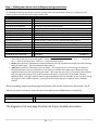
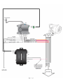
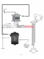
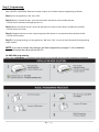
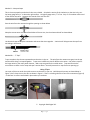
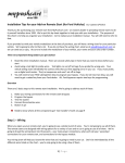
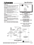
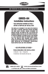
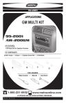
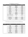
TIP SHEET Installation Tips for your RS-351 + OL-MDB-GM1 (GM1) (3) T3125 v1.1 3/13/14 For: (2005-2009 Buick Allure), (2005-2009 Buick LaCrosse), (2000-2005 Buick LeSabre), (2000-2005 Buick Ultra), (1997-2005 Buick Park Avenue), (2004-2007 Buick Rainier), (2005-2007 Buick Terraza), (2003-2007 Cadillac CTS), (2000-2005 Cadillac Deville), (20032006 Cadillac Escallade), (2003-2006 Cadillac Escallade EXT), (1998-2003 Cadillac Seville), (2000-2004 Cadillac SLS), (2004-2006 Cadillac SRX), (2000-2004 Cadillac STS), (2003-2006 Chevrolet Avalanche), (2003-2006 Chevrolet Silverado), (2004-2006 Chevrolet SSR), (2003-2006 Chevrolet Suburban), (2003-2006 Chevrolet Tahoe), (2002-2009 Chevrolet Trailblazer), (2005-2009 Chevrolet Uplander), (2003-2007 Hummer H2), (2002-2009 GMC Envoy), (2003-2006 GMC Sierra / CK), (2003-2006 GMC Yukon), (2003-2006 GMC Denali), (2003-2008 Isuzu Ascender), (2000-2003 Oldsmobile Aurora), (2002-2004 Oldsmobile Bravada), (2000-2005 Pontiac Bonneville), (2004-2008 Pontiac Grand Prix), (2005-2009 Pontiac Montana), (2006-2009 Saab 97x), (2005-2007 Saturn Relay) Thank you for purchasing your remote start from MyPushcart.com - an industry leader in providing remote starts to doit-yourself installers since 1999. We’ve put this tip sheet together to help you with your installation. The purpose of this sheet is to help you organize your installation - not to replace your installation manual. You will still need to refer to that. If you provided us with your vehicle model/year at the time of purchase, you will have a wiring chart for your particular vehicle. We’re going to refer to that a lot. If you do not have the wiring chart, email us at [email protected] so we can send you a copy. Be sure to include the model/year of your vehicle, your name and your sales order number. Two very important things before you get started: Read the entire installation manual. There are several safety tips in there that you need to know before you start Avoid using a test light to probe wires. Test lights can set off air bags if you probe the wrong wire. Your vehicle wiring chart will identify the correct wires that you’ll be tapping on to in your car. If you must probe, use a digital multi-meter. They’re inexpensive and won’t set off air bags. Overview There are 3 basic steps to this remote start installation. We’re going to address each of these: 1. Make your remote start and bypass wiring connections 2. Program the bypass 3. Test the system and button it up! When you open up your remote start, you’re going to see a whole bunch of wires. You’re not going to use all of them. The remote starts are designed with wiring options for a variety of cars and no car is going to use all of them. We’re going to break the wiring down into only the needed wires you need from the remote starter. Here’s where the vehicle wiring chart comes into play. The wiring chart will help you locate the wires that you’re going to need in your car. Don’t be intimidated by all the different wires listed on the chart – you’re only going to be using a few of them. Reading your wiring chart Each line of the wiring chart contains 3 pieces of information that you will need: The “Circuit” or “Wire/Function” The color of the wire in the car The location of the wire in the car 1|Page Step 1 - Making your remote start and bypass wiring connections: The following table shows you where to connect the wires from your remote start into the car. Any wires on your remote start that are NOT listed in the table are NOT USED. Remote Start Wire: Connect to the wire for the circuit on the vehicle chart labeled: Red (6-pin harness) Constant 12 Volts Red/White (6-pin harness) Constant 12 Volts Pink (6-pin harness) Ignition 12-Volts Pink/White (6-pin harness) Ignition # 2 (not present on all vehicles) Violet (6-pin harness) Starter Orange (6-pin harness) Accessory White (12-pin harness) White/Black (12-pin harness) Black (12-pin harness) Black/White (12-pin harness) Brown/Red (12-pin harness) Grey (12-pin harness) (+) Parking Lamp (IMPORTANT - SEE NOTE 1) (-) Parking Lamp (IMPORTANT - SEE NOTE 1) System Ground – connect this to a solid metal ground in the car Neutral Safety – if you have an automatic transmission, ground this wire Brake switch Hood Input (See NOTE 2) The connections below MAY be needed Green/Black (12-pin harness) OEM Alarm Disarm wire in vehicle Violet/White (12-pin harness) Tach Signal (See NOTE 3) NOTE 1 The remote start has two parking light wires. You will only use one of them. On your vehicle wiring chart, look up the wire for the parking lights. Next to the wire color will be either a “+” or a “-“. If yours has the “+”, then use the white wire. If it has a “-“, use the white/black wire. NOTE 2 The grey wire is used with a pin switch (included in your kit) to prohibit the remote start from activating while the hood is open. This is an important safety feature! NOTE 3 Most vehicles will not require this connection. The remote start has a ‘tach sensing’ circuit built in. The purpose of that circuit (or the tach wire if you need it) is to enable the remote start to detect when the engine has started so it will stop cranking the starter. When you test your system, if the starter keeps cranking after the engine has started, you’ll need to connect the tach wire. Once the wire is connected, take two additional steps: 1) Change “Installer Feature Programming Option # 3 of the Excalibur to the ‘tach wire’ setting (see page 11 in the installer’s manual). 2) Program the tach circuit as shown on page 10 of the installation manual. -Before proceeding, plug the antenna/programming button/LED into the remote start. See Installer’s Tip #1 -Plug the 4 pin data link connector into the data port of the bypass and the GREEN data port of the RS-351. Bypass wire: Connect to: Orange DATA (pin-2 of OBDII plug) Pink Main ignition wire of vehicle -Important: DO NOT use tap connectors on the data wire, solder or wrap and tape this connection. -The diagram on the next page illustrates all of your needed connections: 2|Page 3|Page 4|Page Step 2 - Programming: RS-351 programming: Next, select the “ADS (iData)” Data Port Protocol in option 12 of Installer Feature Programming as follows: Step 1) Turn the ignition key “ON”, then “OFF” Step 2) Within 5 seconds of step 1, press the valet switch 10 times to access installer features. ~ The unit will click and the status light will turn on. Step 3) Within 10 seconds of step 2, press the valet switch 12 times to access option 12 (data port protocol). ~ The unit will click 12 times. Step 4) Change the feature to value 2 by pressing the unlock button on a remote that comes with the RS-351. ~ The unit will click twice. Step 5) To exit programming, turn the ignition key “ON” then “OFF”. Or, you can wait 10 seconds for programming mode to expire. NOTE: If you wish to change more features, see feature programming on page 11 of the installation instructions booklet that comes with the RS-351. OL-MBD-GM1 programming: First, select “DATA MODE” in installation mode selection, then proceed with the module programming procedure: 5|Page Step 3 - Test the system and close it up! Once all your connections are made and programming complete, you should test the system before putting everything back together. 1. Press the ‘lock’ and ‘unlock’ buttons on your remote and confirm that the door locks are operating properly. 2. Press the “start” button on your remote to start the vehicle. The gauges should power up and a in a moment, the vehicle should start. Make sure the vehicle stays running for longer than 10 seconds, and that your climate controls are functional. Stop the engine by stepping on the brake. Once you’ve completed testing the system, it’s time to close it up. Gather up all your wiring and neatly bundle it together using zip ties or electrical tape. Find a secure place to put the remote start module and use zip ties to secure it. Make sure that the remote start wires are not near any moving parts on the steering wheel, pedals or emergency brake! Installer’s Tips: Tip #1 – Where Everything Goes 1. Remote start module – the wiring for the module is done under the dash on the driver’s side, so you’ll want to install the module in that general area. Before you start wiring, look for a location where there’s some open space that will fit the module. Pay attention to moving parts like the pedals, e-brake and steering column. Be sure to route your wiring away from those areas. Bypass module –can be stowed along with the remote start. 2. Antenna/Programming button/Status LED –This typically mounts to the windshield in one of the top corners or behind the rearview mirror. Find a location with clearance and is within its wire reach that is in a visible spot and mount with the double sided tape that is on the back. 3. Hood Pin Switch –An important safety component! Requires a 3/8” hole. Find a location in the engine compartment to mount the switch where the closed hood will keep the plunger in the switch depressed. This is what prevents the car from starting when the hood is open. Tip #2 – How to make your wiring connections It’s very important that all your wiring connections be solid and secure. All remote start connections are “tap on” connections. This means that you do not need to cut the wires in the car. You simply need to “tap on” to the wires in the car to make your connections. Here are three different ways to do this: Method 1 – Solder and tape This is the method preferred by the best professional installers. It makes for the most reliable connections, but it is also the most difficult to do. Sometimes there isn’t enough room in the wiring harness to safely solder a wire without damaging adjacent wires, but if you have the soldering skills, go for it. To make a connection, strip back a section of the insulation on the wire in the car. On heavy gauge wires, 1” is about the right amount. On lighter gauge wires, ½” is fine. Strip 1” of insulation off the end of the remote start wire. Tin the bare section of wire in the car. Wrap the remote start wire around the tinned section and then carefully solder it in place. Wrap the splice tightly with electrical tape. 6|Page Method 2 – Wrap and tape This is the most popular method and is also very reliable. Strip back a section of the insulation on the wire in the car. On heavy gauge wires, 1” is about the right amount. On lighter gauge wires, ½” is fine. Strip 1” of insulation off the end of the remote start wire. Separate the strands of the wire like this: Pass the wire from the remote through the opening as shown below Wrap the remote start wire around both sides of the car wire, then back around itself as shown below Use electrical tape to wrap the connection and secure the wires together. A wire tie will help prevent the tape from unraveling in the future. Method #3 – “T-Taps” T-taps are plastic clips that are squeezed onto the wires in the car. The wire from the remote start goes into the tap and the whole thing is crimped together. T-taps come in different sizes for different size wires. Use yellow t-taps for the larger wires in your main power harness. Red t-taps are good for the smaller wires. Tape and wire tie the connections as shown in the “wrap and tape” section above – that will prevent the t-taps from ever opening up. Using T-Taps Use a pair of pliers to attach the quick-connects to the wires in your car. Hold the quick connect as shown below in Figure 1, then clamp it on to the wire as shown in Figure 2. There is a locking tab at the front of the connector (Figure 3) – make sure it is secure and locked in place when you are done. Figure 1 Figure 2 Copyright 2014 Digitel LLC 7|Page Figure 3