1
RCP-1000 / RCP-1U
Instruction Manual
0. Safety Guidelines.......................................................................................................
1
1. Introduction of Series Models....................................................................................
1
1 .1 Introduction .....................................................................................................
1
1.2 Features .........................................................................................................
1
1.3 Order Information.......................................................................................................
1
1.4 Main Specification......................................................................................................
2
2. Mechanical Specification and Input / Output Terminals............................................
3
2.1 Mechanism of Single Unit.............................................................................................
3
2.2 Mechanism of Whole Rack System.................................................................................
4
3. Functions...................................................................................................................
5
3.1 Input Voltage Range.......................................................................................................
5
3.2 Inrush Current Limiting...................................................................................................
5
3.3 Output Power................................................................................................................
5
3.4 Power Factor Correction (PFC) ........................................................................................
5
3.5 Output Voltage Adjustment.............................................................................................
5
3.6 Fan Speed Control.........................................................................................................
7
3.7 Short Circuit Protection & Over Current Protection.............................................................
7
3.8 Over Voltage Protection (O.V.P.)........................................................................................ 7
3.9 Over Temperature Protection (O.T.P.)................................................................................. 7
3.10 Over Temperature Alarm................................................................................................
7
3.11 AC OK Signal...............................................................................................................
7
3.12 DC OK Signal...............................................................................................................
7
3.13 Fan Malfunction Protection............................................................................................
7
3.14 Remote Control............................................................................................................
7
3.15 Remote Sense..............................................................................................................
7
3.16 Hot-Swap Operation......................................................................................................
8
3.17 Parallel Operation.........................................................................................................
8
3.18 Series Operation........................................................................................................... 9
3.19 Auxiliary Output...........................................................................................................
9
2
3.20 Operation of I C Data Bus (Optional Function)...................................................................
9
4. Notes on Operation........................................................................................................ 12
4.1 Installation Method.........................................................................................................
12
4.2 Derating........................................................................................................................
13
4.3 Warranty.......................................................................................................................
13
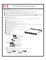
RCP-1000, RCP-1U Instruction Manual
0.Safety Guidelines
¡·Risk of electrical shock and energy hazard. All kinds of failure should be examined by the qualified technician. Please do not
remove the case of the RCP-1000 or RCP-1U by yourself!
¡·Please do not change any component on the RCP series by yourself or make any kind of modification on it.
¡·Please do not install the RCP series in places with high moisture or near the water.
¡·Please do not install the RCP series in places with high ambient temperature or under direct contact of sunlight.
¡·The rated input voltage / frequency are 100~240VAC and 50/60 Hz. Please don't feed in AC power that over ¡Ó10% of the rated value.
¡·Safety protection level of this unit is class I. The grounding wire should be firmly fixed at the "FG" terminal ( ) of the rack. The total
leakage current of the rack system (including 3 * RCP-1000 units and 1 RCP-1U rack) is less than 3.5mA.
1.Introduction of Series Models
1.1 Introduction
RCP series are rack-mounted power supplies that provide power source for telecom equipments, servers, or monitoring
equipments in the 19" racks.
1.2 Features
44 mm low profile, suitable for standard 1U rack applications.
Universal AC input / Full range.
Built-in active PFC function, PF>0.96.
Protections: short circuit / overload / over voltage / over temperature.
Active current sharing up to 3000W (3 units) in one 19" rack ; up to 3 racks (8units maximum) can be connected in parallel.
Remote control for single RCP-1000 unit.
Built-in remote sense function.
Output voltage can be trimmed between 90~110% rated output voltage.
Hot-swap operation.
AC OK and DC OK signal output.
Forced air cooling by built-in DC fan with fan speed control function.
5V / 0.3A auxiliary output.
Built-in ORing diode.
2
I C serial data bus (optional).
3 years warranty.
1.3 Order Information
1.3.1 Explanation for Encoding
¡·
¡·
¡·
¡·
¡·
¡·
¡·
¡·
¡·
¡·
¡·
¡·
¡·
¡·
¡·
Single unit : RCP-1000- 12 - C
2
C : with I C data bus
2
- : without I C data bus
output voltage
1U rack : RCP-1U I
I : IEC320-C14 AC inlet
T : terminal block
Whole system (3 * RCP-1000 + RCP-1U
RCP-3K1U I - 12 - C
¡¼) :
2
C : with I C data bus
2
- : without I C data bus
output voltage
I : IEC320-C14 AC inlet
T : terminal block
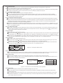
1.3.2 Marking
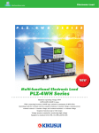
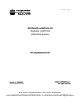
Please refer to the safety label on top of each unit before operating (Figure 1-1~1-3).
Single unit (RCP-1000):
¡·
·¡
RCP-1000-12
INPUT: 100-240VAC
RCP-1000-12-C
13A
INPUT: 100-240VAC
50/60Hz
OUTPUT:
+12V
OUTPUT:
BAUART
GEPRUFT
TUV
Rheinland
Product Safety
TYPE
APPROVED
13A
50/60Hz
60A
+12V
60A
BAUART
GEPRUFT
E183223
LEVEL 5
MADE IN TAIWAN
TUV
Rheinland
Product Safety
TYPE
APPROVED
E183223
LEVEL 5
MADE IN TAIWAN
Figure 1-1: Safety labels of RCP-1000
1
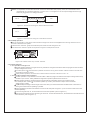
¡·Rack (RCP-1U¡¼):
RCP-1UI
1
2
3
4
5
6
7
8
9
10
11
12
13
14
15
16
17
18
19
20
21
22
23
24
25
100-240VAC
13A EACH INPUT
50/60Hz
INPUT:
MAX. OUTPUT POWER:3024W
48V MODEL:
OUTPUT:
¡¼
48V
63A max.
(21A PER INSTALLED
RCP-1000-48 UNIT)
¡¼24V MODEL:
24V
120Amax.
(40A PER INSTALLED
RCP-1000-24 UNIT)
¡¼12V MODEL:
180A max.
(60A PER INSTALLED
RCP-1000-12 UNIT)
12V
Use only RCP-1000 series power supplies of the
same output voltage rating
BAUART
GEPRUFT
TUV
Rheinland
Product Safety
TYPE
APPROVED
E183223
LEVEL 5
13
1
25
14
RCP-1UT
CN500
ON/OFF (A)
AC-OK (A)
DC-OK (A)
V-TRIM (A)
T-ALARM (A)
+5V-AUX
GND-AUX
ON/OFF (B)
AC-OK (B)
DC-OK (B)
V-TRIM (B)
T-ALARM (B)
NC
CS
ON/OFF (C)
AC-OK (C)
DC-OK (C)
V-TRIM (C)
T-ALARM (C)
+S
-S
+V
SCL (IC)
SDA (IC)
-V
100-240VAC
13A EACH INPUT
50/60Hz
INPUT:
MAX. OUTPUT POWER:3024W
48V MODEL:
OUTPUT:
¡¼
48V
63A max.
(21A PER INSTALLED
RCP-1000-48 UNIT)
¡¼24V MODEL:
24V
120Amax.
(40A PER INSTALLED
RCP-1000-24 UNIT)
¡¼12V MODEL:
12V
180A max.
(60A PER INSTALLED
RCP-1000-12 UNIT)
Use only RCP-1000 series power supplies of the
same output voltage rating
BAUART
GEPRUFT
TUV
Rheinland
Product Safety
MADE IN TAIWAN
TYPE
APPROVED
E183223
LEVEL 5
RCP-3K1UI-12
1
2
3
4
5
6
7
8
9
10
11
12
13
14
15
16
17
18
19
20
21
22
23
24
25
100-240VAC
13A EACH INPUT
50/60Hz
INPUT:
MAX. OUTPUT POWER:2160W
OUTPUT: 12V MODEL:
12V
180A max.
(60A PER INSTALLED
RCP-1000-12 UNIT)
BAUART
GEPRUFT
TUV
Rheinland
Product Safety
TYPE
APPROVED
E183223
LEVEL 5
13
1
25
14
ON/OFF (A)
AC-OK (A)
DC-OK (A)
V-TRIM (A)
T-ALARM (A)
+5V-AUX
GND-AUX
ON/OFF (B)
AC-OK (B)
DC-OK (B)
V-TRIM (B)
T-ALARM (B)
NC
CS
ON/OFF (C)
AC-OK (C)
DC-OK (C)
V-TRIM (C)
T-ALARM (C)
+S
-S
+V
SCL (IC)
SDA (IC)
-V
MAX. OUTPUT POWER:2160W
OUTPUT: 12V MODEL:
12V
180A max.
(60A PER INSTALLED
RCP-1000-12-C UNIT)
BAUART
GEPRUFT
TUV
Rheinland
Product Safety
TYPE
APPROVED
E183223
LEVEL 5
MADE IN TAIWAN
ON/OFF (A)
AC-OK (A)
DC-OK (A)
V-TRIM (A)
T-ALARM (A)
+5V-AUX
GND-AUX
ON/OFF (B)
AC-OK (B)
DC-OK (B)
V-TRIM (B)
T-ALARM (B)
NC
CS
ON/OFF (C)
AC-OK (C)
DC-OK (C)
V-TRIM (C)
T-ALARM (C)
+S
-S
+V
SCL (IC)
SDA (IC)
-V
13
1
25
14
CN500
1
2
3
4
5
6
7
8
9
10
11
12
13
14
15
16
17
18
19
20
21
22
23
24
25
100-240VAC
13A EACH INPUT
50/60Hz
INPUT:
1
2
3
4
5
6
7
8
9
10
11
12
13
14
15
16
17
18
19
20
21
22
23
24
25
¡¼
RCP-3K1UT-12-C
CN500
1
14
MADE IN TAIWAN
Figure 1-2: Safety labels of RCP-1U
¡·Whole system (3 * RCP-1000 + RCP-1U¡¼):
13
25
CN500
ON/OFF (A)
AC-OK (A)
DC-OK (A)
V-TRIM (A)
T-ALARM (A)
+5V-AUX
GND-AUX
ON/OFF (B)
AC-OK (B)
DC-OK (B)
V-TRIM (B)
T-ALARM (B)
NC
CS
ON/OFF (C)
AC-OK (C)
DC-OK (C)
V-TRIM (C)
T-ALARM (C)
+S
-S
+V
SCL (IC)
SDA (IC)
-V
MADE IN TAIWAN
Figure 1-3: Safety labels of the whole RCP system
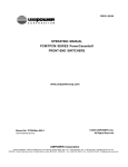
1.4 Main Specification
Single unit
¡·
MODEL
RCP-1000-12
RCP-1000-24
RCP-1000-48
DC VOLTAGE
12V
24V
48V
RATED CURRENT
60A
40A
21A
CURRENT RANGE
0 ~ 60A
0 ~ 40A
0 ~ 21A
RATED POWER
720W
960W
1008W
200mVp-p
300mVp-p
23.2 ~ 24.8V
1.0%
46.3 ~ 49.7V
1.0%
RIPPLE & NOISE (max.) Note.2 150mVp-p
OUTPUT
11.6 ~ 12.4V
VOLTAGE ADJ. RANGE
LOAD REGULATION
¡Ó
Ó¡ 0.5%
Ó¡ 0.5%
SETUP, RISE TIME
1000ms, 60ms/230VAC at full load
LINE REGULATION
16ms/230VAC at full load
HOLD TIME (Typ.)
VOLTAGE RANGE
INPUT
Note.5 90 ~ 264VAC
FREQUENCY RANGE
47 ~ 63Hz
EFFICIENCY (Typ.)
81%
8.5A/115VAC
AC CURRENT (Typ.)
INRUSH CURRENT (Typ.)
LEAKAGE CURRENT
¡Ó
Ó¡ 0.5%
¡Ó0.5%
¡Ó
¡Ó0.5%
¡Ó0.5%
VOLTAGE TOLERANCE Note.3 1.0%
127 ~ 370VDC
4.5A/230VAC
87%
10.5A/115VAC
5.5A/230VAC
89%
11A/115VAC
5.5A/230VAC
COLD START 50A
<1.1mA / 230VAC
105 ~ 125% rated output power
OVER LOAD
PROTECTION OVER VOLTAGE
OVER TEMPERATURE
Protection type : Constant current limiting, recovers automatically after fault condition is removed
13.2 ~ 16.2V
26.4 ~ 32.4V
52.8 ~ 64.8V
Protection type : Shut down o/p voltage, re-power on to recover
75
5 (TSW1) Detect on heatsink of power transistor
85
¢J¡Ó ¢J
¢J¡Ó5¢J (TSW2) Detect on heatsink of power diode
Protection type : Shut down o/p voltage, recovers automatically after temperature goes down
2
¡·Rack system
¡¼
MODEL
OUTPUT
¡¼
RCP-3K1U -24
RCP-3K1U -48
RCP-1000-12
RCP-1000-24
RCP-1000-48
RACK
RCP-1UI or RCP-1UT
OUTPUT VOLTAGE
12V
24V
48V
MAX. OUTPUT CURRENT
180A
120A
63A
2880W
3024W
MAX. OUTPUT POWER Note.6 2160W
VOLTAGE RANGE
Note.5 90 ~ 264VAC
FREQUENCY RANGE
INPUT
4.5A/230VAC
10.5A/115VAC
5.5A/230VAC
11A/115VAC
5.5A/230VAC
LEAKAGE CURRENT
<3.5mA / 230VAC
AUXILIARY POWER
REMOTE ON/OFF CONTROL
5V @ 0.3A
REMOTE SENSE
DC OK SIGNAL
Compensate voltage drop on the load wiring up to 0.5V. "Local Sense"should be connected in order to get the correct output voltage if the "Remote Sense"is not used
AC FAIL SIGNAL
Open collector signal, refer to function manual
OUTPUT VOLTAGE TRIM
Adjustment of output voltage, possible between 90 ~ 110% of rated output
OVER TEMP WARNING
WORKING TEMP.
Logic " High" for over temperature warning, refer to function manual
-20 ~ +60 (Refer to "Derating Curve")
WORKING HUMIDITY
ENVIRONMENT STORAGE TEMP., HUMIDITY
TEMP. COEFFICIENT
VIBRATION
SAFETY STANDARDS
SAFETY & WITHSTAND VOLTAGE
ISOLATION RESISTANCE
EMC
(Note 4)
EMC EMISSION
OTHERS
127 ~ 370VDC
47 ~ 63Hz
AC CURRENT (Typ.)FOR EACH UNIT 8.5A/115VAC
FUNCTION
¡¼
RCP-3K1U -12
MODULE
By electrical signal or dry contact
ON:short
OFF:open
¡Ù80%¡Ó5%, max. sink current:10mA
Open collector signal, on when Vout
¢J
20 ~ 90% RH non-condensing
¢J, 10 ~ 95% RH
¡Ó0.02%/¢J (0 ~ 50¢J)
-40 ~ +85
10 ~ 500Hz, 2G 10min./1cycle, 60min. each along X, Y, Z axes
UL60950-1, TUV EN60950-1 approved
I/P-O/P:3KVAC I/P-FG:2KVAC O/P-FG:0.7KVDC
I/P-O/P, I/P-FG, O/P-FG:100M Ohms / 500VDC / 25
¢J/ 70% RH
Compliance to EN55022 (CISPR22) Class B, EN61000-3-2,-3
EMC IMMUNITY
Compliance to EN61000-4-2,3,4,5,6,8,11, EN61000-6-2 (EN50082-2), heavy industry level, criteria A
DIMENSION
Rack 483.6*350.8*44(L*W*H)
11Kg; 1pcs/11Kg/2.67CUFT
PACKING
¢J
1. All parameters NOT specially mentioned are measured at 230VAC input, rated load and 25 of ambient temperature.
2. Ripple & noise are measured at 20MHz of bandwidth by using a 12" twisted pair-wire terminated with a 0.1uf & 47uf parallel capacitor.
3. Tolerance : includes set up tolerance, line regulation and load regulation.
4. The power supply is considered a component which will be installed into a final equipment. The final equipment must be re-confirmed that it still meets
EMC directives.
5. Derating may be needed under low input voltages. Please check the derating curve for more details.
6. Output of all the RCP-1000 modules are connected in parallel in the rack.
7. Under parallel operation of more than one rack connecting together, ripple of the output voltage may be higher than the SPEC at light load condition.
It will go back to normal ripple level once the output load is more than 10%.
NOTE
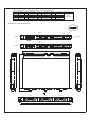
2.Mechanical Specification and Input / Output Terminals
2.1 Mechanism of Single Unit
295
41
24
DC OK AC OK
46
127
CN501
Air flow
direction
1
3
5 7 10 13 16 19
2
4
6 9 12 15 18 21 22
23
24
3
Input / Output Connector Pin. No Assignment(CN501) : Postronic P CIB24W9M400A1
Pin No.
Assignment
+V
-V
ON/OFF
+S
-S
1,2,4
3,5,6
7
8
9
Pin No.
Assignment
AC_OK
DC_OK
CS
V_TRIM
T_ALARM
10
11
12
13
14
Pin No.
15
16
17
18
19
Assignment
+5V_AUX
GND_AUX
SDA
SCL
A0
Pin No.
20
21
22
23
24
Assignment
A1
A2
FG
AC/ L
AC/ N
Mating Housing
Postronic
PCIB24W9F400A1
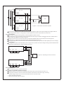
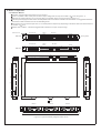
2.2 Mechanism of Whole Rack System
Address
Switch
-
14
25
1
13
CN500
+
14
25
1
13
LC NC LB NB LA NA
RCP-1UT
10
8
Address
Switch
C
Mounting Bracket
B
A
-
RCP-1UI
CN500
+
14
25
1
13
24
50
3-M5 L=6mm
3-M5 L=6mm
22
22
Air flow
direction
Module B
DC OK AC OK
DC OK AC OK
Module A
31.8
Module C
10.6
466.2
DC OK AC OK
6.1
44
7.1
50
125
125
350.8
125
125
440
483.6
4
Connector Pin No. Assignment(CN500) : D-Type Right Angle 25 positions
Pin No.
Assignment
ON/OFF-A
AC-OK-A
DC-OK-A
V-TRIM-A
T-ALARM-A
1
2
3
4
5
Pin No.
6
7
8
9
10
Pin No.
Assignment
+5V-AUX
GND-AUX
ON/OFF-B
AC-OK-B
DC-OK-B
11
12
13
14
15
Assignment
V-TRIM-B
T-ALARM-B
NC
CS
ON/OFF-C
Pin No.
16
17
18
19
20
Assignment
AC-OK-C
DC-OK-C
V-TRIM-C
T-ALARM-C
+S
Pin No.
21
22
23
24
25
Assignment
-S
+V
SCL
SDA
-V
¡·Description of CN500 in/out connection pins
Pin No.
1,8,15
2,9,16
3,10,17
4,11,18
5,12,19
6
7
Function Description
ON/OFF Each unit can separately turn the output on and off by electrical or dry contact between ON/OFF A,B,C(pin 1,8,15) and -S(pin 21). Short: ON, Open:OFF.
AC-OK High : When the input voltage is 82Vrms +/-4V. Low : when the input voltage in 82Vrms +/-4V.
DC-OK High : When the Vout 80%+/-5%. Low : When Vout 80%+/-5%
V-TRIM Connection for output voltage trimming. The voltage can be trimmed within its defined range.
T-ALARM High : When the internal temperature is within safe limit. Low : 10 below the thermal shut down limit.
+5V-AUX Auxiliary voltage output, 4.3~5.3V, referenced to GND-AUX(pin 7). The maximum load current is 0.3A. This output has the built-in
"Oring diodes" and is not controlled by the remote ON/OFF control.
¡Ù
¡Ù
¡Ø
¡Ø
¢J
GND-AUX Auxiliary voltage output GND. The signal return is isolated from the output terminals (+V & -V).
Current sharing signal. When units are connected in parallel, the CS pins of the units should be connected to allow current balance
CS
between units.
14
20
+S
Positive sensing. The +S signal should be connected to the positive terminal of the load. The +S and -S leads should be twisted in pair to
minimize noise pick-up effect. The maximum line drop compensation is 0.5V.
21
-S
Negative sensing. The -S signal should be connected to the negative terminal of the load. The -S and +S leads should be twisted in pair to
minimize noise pick-up effect. The maximum line drop compensation is 0.5V.
22
23
24
25
+V
SCL
SDA
-V
Positive output voltage. For local sense use only, can't be connected directly to the load.
2
2
Serial clock used in the I C interface option. Refer to the I C interface description.
2
2
Serial data used in the I C interface option. Refer to the I C interface description.
Negative output voltage. For local sense use only, can't be connected directly to the load.
3.Functions
3.1 Input Voltage Range
Nominal input voltage range is AC 90~264V or DC 127~370V.
To insure proper operation, AC input should be within the pre-specified range. The wrong input will cause the power supply to
operate improperly, lose the PFC function or even be damaged.
Since the RCP Series have built-in active PFC circuit, there will be lower efficiency and output derating is required when
operating at lower input voltage (<100VAC).
¡·
·¡
·¡
3.2 Inrush Current Limiting
Built-in inrush current limiting circuit.
The external switch, if needed, should have a current rating exceeding the maximum inrush current.
Since the inrush current limiting circuit mainly consists of thermistor and relay, after turning off the power supply, a 10 second cool
down period is recommended before turning it back on. Inrush current will be much higher than the specified value if input thermistor
is not allowed sufficient time to cool down.
¡·
¡·
¡·
3.3 Output Power
Single Unit
RCP-1000-12 : 720W (12V / 60A)
RCP-1000-24 : 960W (24V / 40A)
RCP-1000-48 : 1008W (48V / 21A)
Whole System
RCP-3K1U -12 : 2160W (12V / 180A)
RCP-3K1U -24 : 2880W (24V / 120A)
RCP-3K1U -48 : 3024W (48V / 63A)
¡·
¡·
¡¼
¡¼
¡¼
3.4 Power Factor Correction (PFC)
Built-in active power factor correction (PFC) function. Under full load output and the input voltage is within the range of
90~230Vac, PF>0.96; if the output is less than full load or the input voltage is higher than 230Vac, the PF value will be
a little less than 0.96.
¡·
3.5 Output Voltage Adjustment
3.5.1 Adjustment of single unit
Output voltage of one RCP-1000 is adjustable through the potentiometer (SVR51, can be found under the small circular
hole on top of the unit). Please use a cross-screwdriver with isolated holder to make the adjustment.
3.5.2 Adjustment of single unit or the whole rack system
Output voltage difference of each unit in the same rack should be maintained within 1%, or the effectiveness of current
sharing might be influenced.
Output voltage can be adjusted between 90%~110% of rated value by adding external resistors (R1 and R2). Please refer
to Figure 3-1for details.
When the output is tuned to a higher voltage, please notice that the load current should be decreased accordingly. The
output wattage of each unit should not exceed its rated value under any circumstances.
¡·
¡·
¡·
¡Ó
5
3.5.3 Wiring of output voltage adjustment (use voltage trimming function)
RCP-1U
+S
V-TRIM-A
V-TRIM-B
V-TRIM-C
-S
20
4
11
18
21
R1
R1
R1
R2
R2
R2
Figure 3-1: Voltage trimming by using external resistors
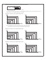
The resistors R1, R2 mentioned in Figure 3-1 should be added independently and the minimum wattage rating is 0.1W.
Please refer to 3.5.4~3.5.6 about the selection of resistance.
3.5.4 Reference resistance value of R1/R2 for RCP-1000-12
Vout (%)
Vout (%)
100
110
98
108
96
106
94
104
92
102
90
100
180K
240K
350K
560K
1.2M
NC
£[
R1 ( )
min. 0.1W
NC
300K
£[
120K
62K
31K
13K
R2 ( )
min. 0.1W
Note: For adjustment under 100% of rated output voltage, R2 should be opened.
For adjustment over 100% of rated output voltage, R1 should be opened.
3.5.5 Reference resistance value of R1/R2 for RCP-1000-24
Vout (%)
Vout (%)
100
110
98
108
96
106
94
104
92
102
90
100
560K
750K
1M
1.6M
3.3M
NC
£[
R1 ( )
min. 0.1W
£[
NC
330K
130K
62K
30K
10K
R2 ( )
min. 0.1W
NC
345K
140K
70K
36K
15K
R2 ( )
min. 0.1W
3.5.6 Reference resistance value of R1/R2 for RCP-1000-48
Vout (%)
Vout (%)
100
110
98
108
96
106
94
104
92
102
90
100
1.3M
1.7M
2.4M
3.6M
7.6M
NC
£[
R1 ( )
min. 0.1W
£[
6
3.6 Fan Speed Control
Built-in fan speed control circuit. The fan speed will be adjusted according to the magnitude of output load.
¡·
·¡
3.7 Short Circuit Protection & Over Current Protection (O.C.P.)
Protection comes into effect at short circuit condition or >115% 10% of output rated current (constant current limiting mode).
The PSU will automatically recover once the short circuit / over current condition is removed.
¡Ó
3.8 Over Voltage Protection (O.V.P.)
Built-in over voltage protection circuit for each RCP-1000 unit.
The O.V.P. triggering points are different for different output models. Please refer to the specification sheet for details.
The PSU shuts down when O.V.P. is triggered. To restart the power supply, please switch off AC input first and then wait for
10 seconds before switching it back on.
¡·
¡·
¡·
3.9 Over Temperature Protection (O.T.P.)
Built-in 2 sets of over temperature protection circuit. When the internal temperature exceeds the threshold value, the power
supply will shut down automatically (the built-in fan will still operate to cool down the PSU). You should switch off the AC input
and remove all possible causes of overheating, and then let the power supply cool down to normal working temperature
(needs about 10 minutes~1hour) before turning it back on.
If the internal temperature is under the threshold value, there will be a "Low" signal (0~0.5V) between "T-ALARM" and "-V" on
CN500; if the internal temperature exceeds the threshold value, there will be a "High" signal (4.5~5.5V) between "T-ALARM"
and "-V" on CN500 connector.
¡·
¡·
3.10 Over Temperature Alarm
Every RCP-1000 single unit has a detecting circuit to sense its internal temperature. The value of internal temperature can
2
only be read through the I C interface: when the internal temperature of RCP-1000 is higher than 60
3 , there will be an
2
alarm signal sent out through the I C interface.
¡·
¢J¡Ó ¢J
3.11 AC OK Signal
Built-in AC input voltage detecting circuit.
When AC input voltage 82V 4V, the output voltage can start to work properly and the "AC OK" LED on the front panel will light
up (see Figure 3-2). In the mean time, there will be a "Low" signal (0~0.5V) between "AC-OK" and "-V" on CN500 connector.
When AC input voltage 82V 4V, the output voltage will be shut down and the "AC OK" LED on the front panel will be turned off.
In the mean time, there will be a "High" signal (4.5~5.5V) between "AC-OK" and "-V" on CN500 connector.
¡·
·¡
¡·
¡Ù Ó¡
¡Ø Ó¡
3.12 DC OK Signal
Built-in DC output voltage detecting circuit.
When DC output voltage 80% 5% of rated value, the "DC OK" LED on the front panel will light up (see Figure 3-2). In the
mean time, there will be a "Low" signal (0~0.5V) between "DC-OK" and "-V" on CN500 connector.
When DC output voltage 80% 5% of rated value, the "DC OK" LED on the front panel will be turned off. In the mean time,
there will be a "High" signal (4.5~5.5V) between "DC-OK" and "-V" on CN500 connector.
¡·
¡·
¡·
¡Ù
¡Ø
¡Ó
¡Ó
Figure 3-2: Front panel of RCP-1000
DC OK AC OK
3.13 Fan Malfunction Protection
Built-in fan malfunction protection circuit. When the DC fan stop operating (fan lock or wire broken), the output will be shut
down. Please switch off the AC source and send back to our local distributor or MEAN WELL for repair.
¡·
3.14 Remote Control
Built-in remote ON/OFF control circuit. Please refer to Figure 3-3 for single unit or whole rack control.
Notice that the "ON/OFF" and "-S" pin on CN500 should be short connected in order to let the PSU operate properly. If it is
open, the output voltage will be shut down.
¡·
·¡
RCP-1U
ON/OFF A
ON/OFF B
ON/OFF C
1
8
15
SW
-S 21
Whole rack ON/OFF
RCP-1U
ON/OFF A
ON/OFF B
ON/OFF C
1
8
15
Between "ON/OFF" Output
and "-S" on CN500 Status
SW
-S 21
SW Open
OFF
SW Short
ON
Single unit ON/OFF
Figure 3-3: Connection for remote ON/OFF control operation
3.15 Remote Sense
Built-in remote sense circuit that can compensate voltage drop up to 0.5V.
When using this function, the sensing wires should either be twisted or shielded to prevent external noise interference.
(refer to Figure 3-4)
The voltage drop across the output wires must be limited to less than 0.5V. Also heavy wires with adequate current rating
should be used between +V/-V and the load. Please firmly connect the output wires to prevent them from loosing, or the
power supply may be out of order.
¡·
·¡
¡·
7
¡·Notice: It is required to use the "Remote Sense" function to let the PSU work properly. If not, the "Local Sense" is still
required that "+S" should be shorted to "+V" and "-S" to "-V" as Figure 3-5. Or the output voltage will be too high
which may trigger the over voltage protection.
+V
(CN500) +S
+V
RCP-1U
LOAD
(CN500) -S
-V
-V
Twisted wires
Figure 3-4: Connection for using the "Remote Sense" function
CN500
+V
RCP-1U
+S
-V
-S
22
20
25
21
Figure 3-5: Connection for using the "Local Sense" function
3.16 Hot-Swap Operation
Built-in "Oring diode" in every RCP-1000 unit that the single unit can be hot-swapped without turning off the AC source
provide to the whole rack system.
Insert the RCP-1000 unit: grasp the handle and push inside the rack through the rail.
Pull out the RCP-1000 unit: press the clip shown in Figure 3-6 and pull the unit out.
·¡
¡·
¡·
DC OK AC OK
Clip
Figure 3-6: Location of the "clip" on RCP-1000 unit
3.17 Parallel Operation
3.17.1 Operation of single rack
Internal parallel operation in single rack is only suitable for using the same RCP-1000 unit (single unit with the same
output voltage and current).
Each rack (RCP-1U ) have the built-in parallel connection / wiring. Once the RCP-1000 unit insert in the rack then
the parallel connection is done.
Under parallel operation, the connection of other functions can refer to section 3.14 & 3.15.
3.17.2 Operation of three racks in parallel
Parallel operation is only suitable for the same RCP-1000 unit (single unit with the same output voltage and current)
located in up to 3 racks. Totally 8 identical single units operate in parallel is the maximum.
Under parallel operation, the total output current should not exceed 90% of the sum of rated currents.
For example: RCP-1000-24 8 connected in parallel (in 3 racks), the maximum output current should be
40A 8 unit 0.9 = 288A
Adjust the output voltage of all the single units to the value you need and minimize the differences to less than 1%
among one another before operating in parallel.
Please paralleling the racks first and then connect to the load (refer to Figure 3.7). Do not connect each rack to the
load separately!
The control signals CS, +S, -S should also be connected in parallel. (refer to Figure 3.7)
Twisted wires should be used for the wiring of +S and -S. To avoid the interference, the twisted wires should not touch
the load wires. (refer to Figure 3.7)
·¡
¡·
¡·
¡·
·¡
¡·
·¡
·¡
·¡
¡¼
¡Ñ
¡Ñ
¡Ñ
8
CN500
14
20
21
01
08
15
CS
+S
RCP-1U#1
-S
ON / OFF-A
ON / OFF-B
ON / OFF-C
+V
-V
CN500
14
20
21
01
08
15
CS
+S
RCP-1U#2
-S
ON / OFF-A
ON / OFF-B
ON / OFF-C
+V
+S
LOAD
-S
+V
-V
-V
Twisted
wires
CN500
14
20
21
01
08
15
CS
+S
RCP-1U#3
-S
ON / OFF-A
ON / OFF-B
ON / OFF-C
Figure 3.7: Three racks connected in parallel
+V
-V
¡·Under parallel operation of more than one rack connecting together, ripple of the output voltage may be higher than the
SPEC at light load condition. It will go back to normal ripple level once the output load is more than 10%.
3.18 Series Operation
Higher output voltage can be acquired by connecting different racks in series.
The racks (RCP-1U ) connected in series should have the same single unit (RCP-1000- ) in each rack. Please refer to
Figure 3-8 for the reference connection method.
Output current for series connection should not exceed the smallest rated current of all series connecting racks.
The difference in rise times of individual rack will lead to steps/stairs like turn on.
The output voltage after series connection should be less than 60Vdc [the requirement of SELV(Safety Extra Low Voltage)
of IEC60950-1].
It is suggested to add on external diodes shown in Figure 3-8 to prevent the reverse voltage. Rating of these diodes should
higher than the total amount of output voltage and current.
¡·
·¡
·¡
¡·
¡·
·¡
¡¼
¡¼
RCP-1U#1
+V
+S
ON/OFF
ON/OFF
A
1
B
C
8
-S
ON/OFF
-S
15
20
21
(*)
-V
21
+V
LOAD
-V
RCP-1U#2
+V
+S
ON/OFF
ON/OFF
B
A
1
Figure 3-8: Operating in series connection
C
8
-S
ON/OFF
-S
15
20
21
(*)
-V
21
3.19 Auxiliary Output
Built-in 5V/0.3A auxiliary output for each rack.
¡·
2
3.20 Operation of I C Data Bus (Optional Function)
¡·Models with built-in I C function are available, please refer to the order information in section 1.3.
·¡ Through the I C interface, users can obtain the operation information of the power supply, including.
2
2
1. Output voltage, output current, and internal temperature of the power supply.
2. Alarm and status information.
3. Manufacturing and model information.
9
2
3.20.1 Block diagram of I C data bus and related components
AC Input Fail
Output Power Good
Temperature Waring
Over Temperature Protection
Fan Fail
A0
A1
PCF8574
Register
A2
A0
A1
PCF8591
A/D Converter
A2
A0
A0
A1
A1
A2
A2
AT24C02
EEPROM
SCA
SDL
2
I C bus
2
3.20.2 Address of I C bus
Address is set by a 9-pole DIP switch on the rack. There are totally 3 RCP-1000 units in one RCP-1U
RCP-1000 has 3-pole as the addressing switch. (refer to the following diagram)
¡¼ rack and each
ON
1 2 3 4 5 6 7 8 9
OFF
Module A Module B Module C
The "ON" position represents logic "0" while the "OFF" position represents logic "1". Switch 1~3, 4~6, 7~9 (low
can set RCP-1000 unit at position A, B, C in the rack respectively. Please refer to the following table.
A2
A1
A0
Module
3
2
1
A
6
5
4
B
9
8
7
C
¡¼
¡÷high bit)
2
For example, if we want to set the Module A of RCP-3K1U -X as the first unit in the I C data bus, Module B as the second,
and Module C as the third, then we should set the 9-pole DIP switch on the rack as follow:
ON("0")
1 2 3 4 5 6 7 8 9
OFF("1")
Module A Module B Module C
"1"
"2"
"3"
3.20.3 Digital status display function (Read Only)
2
Digital status functions are provided by a PCF8574, 8-bit register. It provides a single 8-bit word when read by the I C
controller. "Fault" is indicated by "1" while "Good" level is indicated by "0". The following table specifies the corresponding
status for each bit:
Bit
0
1
2
3
4
5
6
7
Function
AC Input Fail
Output Power Good / Fail
Temperature Warning
Over temperature Protection
Fan Fail Warning
Not Used
Not Used
Not Used
Good Fault
0
1
0
1
0
1
0
1
0
1
-------------
Description
AC input normal / abnormal
Output voltage is less than the SPEC
Internal temperature is over 60 , PSU is still on
Temperature exceeds normal operating limit, PSU turns off
Fan fail or stop working
-------
¢J
10
PCF8574 slave address:
Bit
7
6
5
Value
0
1
0
4
0
3
A2
2
A1
1
A0
0
R/W
Read : 1
Write : 0
3.20.4 Analog status display function (Read Only)
1.Analog functions are provided by a single PFC8591, 4-channel 8-bit A/D converter. When this device is read by the
serial bus controller, it provides an 8-bit word with the following information:
A/D Channel
1
2
3
4
Information
Output voltage
Output Current
Internal Temperature
Not Used
2.PCF8591 slave address
Bit
7
6
5
1
0
0
Value
3.PCF8591 control byte
Bit
7
6
5
0
0
0
Value
4
1
3
A2
2
A1
1
A0
0
R/W
Read : 1
Write : 0
4
0
3
0
2
0
1
0
0
0
1
0 : output voltage
1 : output current
0 : internal temperature
4.A/D scaling
The following scaling should be employed:
Value (voltage, current, temperature) = Byte Value * Resolution
Please refer to the following table for the scaling of the A/D channels for each model:
RCP-1000-12
Voltage
Current
Temperature
Range
0~16V
0~80A
0~100
Resolution
0.0625V/bit
0.312A/bit
0.391 /bit
Accuracy
5%
10%
3
RCP-1000-24
Voltage
Current
Temperature
Range
0~33V
0~55A
0~100
Resolution
0.129V/bit
0.215A/bit
0.391 /bit
Accuracy
+3,-5%
10%
3
RCP-1000-48
Voltage
Current
Temperature
Range
0~65V
0~30A
0~100
Resolution
0.254V/bit
0.117A/bit
0.391 /bit
Accuracy
+2,-5%
10%
3
¢J
¢J
¢J
¢J
¢J
¢J
¡Ó
¡Ó
¡Ó ¢J
¡Ó
¡Ó ¢J
¡Ó
¡Ó ¢J
For example, if the temperature reading value of RCP-1000-24 is "01010010", then convert to decimal value will be "82"
82(value) * 0.391(resolution) = 32.062
¢J
3.20.5 Function of EEPROM (Read Only)
2
A 256-byte EEPROM (AT24C02) includes in the I C option which stores some information related to the model and
manufacturing data. It is programmed at the factory with the data shown below:
Address
4
20
40
56
72
88
104
254
Bytes
16
20
16
16
16
16
16
2
The slave EEPROM address:
Bit
7
6
5
4
Value
1
0
1
0
Data
Manufacturer
Serial Number
Revision
Country of Production
Model Name
Output Voltage
Data of Production
Checksum
3
A2
2
A1
1
A0
0
R/W
Read : 1
Write : 0
11
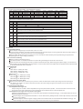
4.Notes on Operation
4.1 Installation Method
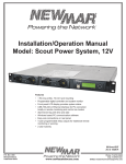
The RCP-1U should be mounted in the 19" rack first.
Insert 1~3 pieces of RCP-1000 (with the same output voltage and current) into the RCP-1U (refer to Figure 4-1).
Definition of module position: A is on the right, B is in the middle, and C is on the left (refer to Figure 4-1).
This is a power supply with built-in DC fan and please make sure that the ventilation is not blocked. It is suggested that there
should be no barriers within 10cm of the ventilating holes.
Connect AC source to the AC input for A, B, C module position respectively depending on the RCP-1000 units assembled into
the RCP-1U rack.
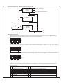
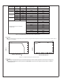
Please refer to Table 4-1 about the suggested wire selection for input / output wirings.
¡·
¡·
¡·
·¡
·¡
·¡
¡¼
¡¼
¡¼
AC Input(C,B,A)
Frame Ground
Address
Switch
DC Output
-
CN500
+
14
25
1
13
LC NC LB NB LA NA
RCP-1UT
10
8
AC Input (C,B,A)
C
Mounting Bracket
B
A
Address
Switch
DC Output
-
CN500
+
RCP-1UI
14
25
1
13
24
50
3-M5 L=6mm
3-M5 L=6mm
22
22
Air flow
direction
Module B
DC OK AC OK
DC OK AC OK
Module A
31.8
Module C
10.6
DC OK AC OK
466.2
6.1
44
7.1
50
125
125
350.8
125
125
440
483.6
Figure 4-1: System assembly diagram of RCP series
12
Input /Output
Module
Current
110VAC
220VAC
1 unit
1 unit
1 unit
2 unit
3 unit
1 unit
2 unit
3 unit
1 unit
2 unit
3 unit
12Arms
6Arms
60Adc
120Adc
180Adc
40Adc
80Adc
120Adc
21Adc
42Adc
63Adc
+12VDC
+24VDC
+48VDC
Minimum Cross-section
of Copper Wire
14AWG UL1015
18AWG UL1015
Maximum Current
12A
6A
61A
115A
162A
37A
88A
115A
27A
49A
61A
8A
22A
35A
139A
190A
217A
257A
298A
344A
395A
469A
556A
8mm 2
22mm2
38mm2
3.5mm2
14mm2
22mm2
2mm 2
5.5mm2
8mm 2
16AWG UL1015
12AWG UL1015
10AWG UL1015
30mm 2
50mm 2
60mm 2
80mm 2
100mm2
125mm2
150mm2
200mm2
250mm2
Suggested selection for frequent
used wirings
Table 4-1: Suggested wire selection for input / output wirings
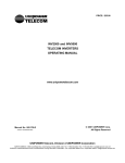
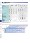
4.2 Derating
Output load derating is required for proper operation in high ambient temperature or at low AC input voltage. Please refer to
Figure 4-2 for details.
¡·
¢J
Ta=25
100
100
90
80
80
70
LOAD (%)
LOAD (%)
60
40
20
-20
60
50
40
0
10
20
30
40
50
¢J
AMBIENT TEMPERATURE ( )
60
70
90
95
100
115
264
INPUT VOLTAGE (VAC) 60Hz
Figure 4-2: Output derating curves for RCP series
4.3 Warranty
Three years of global warranty is provided for RCP series under normal operation. Please do not change any
component or modify the unit by yourself or MEAN WELL may reserve the right not to provide the complete
warranty service.
¡·
13