1
Yaskawa Siemens CNC Series
Maintenance Manual
Serviceman Handbook
MANUAL No. NCSIE-SP02-19
Yaskawa Siemens Numerical Controls Corp. has been merged to Siemens K.K. and
Siemens Japan K.K. as of August, 2010 respectively. "Yaskawa Siemens Numerical
Controls Corp." in this manual should therefore be understood as "Siemens Japan K.K."
This manual is intended for both of Yaskawa Siemens 840DI and Yaskawa Siemens 830DI.
In this manual, the functional differences of these two models are not taken into account in
its description, thus please refer to the catalog (MANUAL No.: NCKAE-PS41-01) for
available basic functions and possible optional functions of each model.
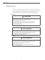
Safety-related symbol marks
Safety-related symbol marks
The following symbol marks are used in this manual to draw special attention to safety
information.
The information next to these symbol marks is important for safety and thus must always be
followed.
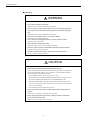
WARNING
CAUTION
Indicates activities that could result in a dangerous condition, including death and
serious injury, if done wrongly.
Indicates activities that could result in a dangerous condition, including major and
minor injury, or in damage to objects, if done wrongly.
It is noted that those activities as indicated by the
CAUTION
symbol mark could even
result in death or serious injury if done wrongly in a worst-case situation.
PROHIBITED
MANDATORY
Indicates what you must not do. For example, the
mark means that you must
not make or use a fire here.
Indicates what you must do unconditionally. For example, the
ground mark
means that you must always ground the object you are working with.
iii
Icons
Icons
The following icons are used as necessary throughout this manual to categorize description
next to them:
IMPORTANT
Indicates what you must always keep in mind. If the instruction were not fully followed, an
error could occur that might not damage a machine or other objects but would result in an
alarm.
EXAMPLE
Indicates program examples or operation examples.
Indicates additional information or what you should keep in mind for better efficiency.
INFO
Indicates unfamiliar technical terms or those not defined in the text. Description of such
TERMS
terms will follow.
Copyright (C) 2001 Yaskawa Siemens NC Co., Ltd.
Part or the whole of this manual may not be reproduced or copied without written
permission.
iv
Table of Contents
Table of Contents
Safety-related symbol marks.........................................................................iii
Icons............................................................................................................. iv
Table of Contents .......................................................................................... v
Outline of this manual...................................................................................xii
Related manuals ..........................................................................................xii
How to use this manual ............................................................................... xiii
Trademarks ................................................................................................. xiii
Safety precautions.......................................................................................xiv
Warning labels...........................................................................................xxiv
Part 1 Hardware
Chapter 1 System Configuration ....................................1-1
1.1 System configuration...................................................................1-2
1.1.1 General wiring drawing............................................................................... 1-2
1.1.2 List of system components ......................................................................... 1-4
1.2 Meanings of component designations.........................................1-8
1.2.1 SERVOPACK designations ........................................................................ 1-8
1.2.2 Servo motor designations.........................................................................1-10
1.2.3 Spindle motor designations ...................................................................... 1-11
Chapter 2 Installing the control panels...........................2-1
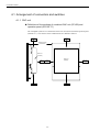
2.1 Designing the panels...................................................................2-2
2.1.1 Environmental conditions for installing the control panels and other sy
stem components ....................................................................................... 2-2
2.1.2 Thermal design of the enclosures .............................................................. 2-3
2.1.3 Heat dissipation .......................................................................................... 2-6
2.1.4 Power consumption .................................................................................... 2-8
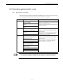
2.2 Protecting against electric noise..................................................2-9
2.2.1 Separation of cables................................................................................... 2-9
2.2.2 Noise-proof devices..................................................................................2-10
2.2.3 Grounding.................................................................................................2-12
2.2.4 Cable shield clamp ...................................................................................2-13
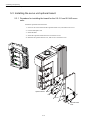
2.3 Installation precautions..............................................................2-14
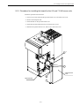
2.3.1 Installing the CNC units ............................................................................2-14
2.3.2 Installing the feed/spindle SERVOPACK .................................................. 2-15
2.3.3 Orientation of and installation space for the SERVOPACK ...................... 2-16
2.3.4 Installation space for the I/O modules ......................................................2-17
2.3.5 Installing lightning-surge absorbers..........................................................2-18
v
Table of Contents
Chapter 3 Installing the motors .....................................3-1
3.1 Servo motors .............................................................................. 3-2
3.2 Spindle motors ............................................................................ 3-3
Chapter 4 Connection method ......................................4-1
4.1 Arrangement of connectors and switches................................... 4-2
4.1.1 CNC unit ..................................................................................................... 4-2
4.1.2 Power supply module ................................................................................. 4-6
4.1.3 I/O module .................................................................................................. 4-6
4.1.4 Converter.................................................................................................... 4-9
4.1.5 Inverter ..................................................................................................... 4-10
4.1.6 Servo unit ................................................................................................. 4-11
4.2 Power on/off signals.................................................................. 4-14
4.2.1 Wiring for servo power-on and other signals ............................................ 4-14
4.2.2 UPS module timer setting......................................................................... 4-17
4.2.3 Time chart................................................................................................. 4-18
4.3 Wiring units and devices ........................................................... 4-19
4.3.1 PROFIBUS-DP address and termination setting...................................... 4-19
4.3.2 Setting the rotary switches on the inverters and servo units .................... 4-21
Chapter 5 Assembling and replacing .............................5-1
5.1 Installing the CNC unit ................................................................ 5-2
5.2 Replacing the servo unit fan ....................................................... 5-8
5.2.1 Procedure for replacing the 0.5-3.0 and 5.0 kW servo unit fans ................ 5-8
5.2.2 Procedure for replacing the 6.0 and 7.5 kW servo unit fans....................... 5-9
5.3 Installing the servo unit optional board ..................................... 5-10
5.3.1 Procedure for installing the board for the 0.5-3.0 and
5.0 kW servo units.................................................................................... 5-10
5.3.2 Procedure for installing the board for the 6.0 and
7.5 kW servo units.................................................................................... 5-11
Part 2 Software
Chapter 6 Software configuration ..................................6-1
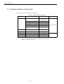
6.1 System software components..................................................... 6-2
6.2 Data types................................................................................... 6-3
6.3 Service screen directories........................................................... 6-4
vi
Table of Contents
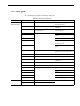
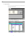
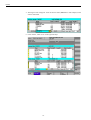
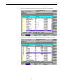
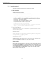
Chapter 7 Backup ..........................................................7-1
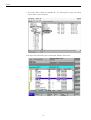
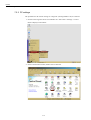
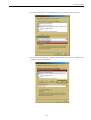
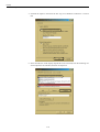
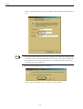
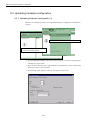
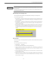
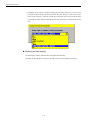
7.1 How to archive.............................................................................7-2
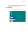
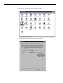
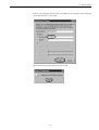
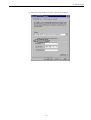
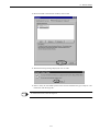
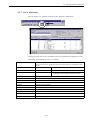
7.2 Network settings..........................................................................7-7
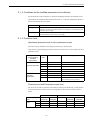
7.2.1 YS 840DI settings....................................................................................... 7-7
7.2.2 PC settings ............................................................................................... 7-14
Part 3 PLC
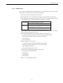
Chapter 8 General programming notes .........................8-1
8.1 LAD/FBD/STL compatibility.........................................................8-2
8.2 Program structure........................................................................8-3
8.3 Address structure ........................................................................8-4
8.3.1 Address symbols ........................................................................................ 8-4
8.3.2 Bit address.................................................................................................. 8-4
8.3.3 Addressing of input, output, bit memory, and data bits............................... 8-5
8.3.4 Addressing of timers and counters ............................................................. 8-5
8.4 Interface structure .......................................................................8-6
8.4.1 General....................................................................................................... 8-6
8.4.2 Signals through the PLC/NC interface........................................................ 8-6
8.4.3 Data blocks................................................................................................. 8-7
8.4.4 Program components ................................................................................. 8-8
Chapter 9 SIMATIC manager and hardware
configuration .................................................9-1
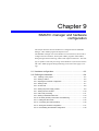
9.1 Hardware configuration ...............................................................9-3
9.2 Defining the hardware .................................................................9-4
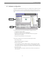
9.2.1 Creating a new project................................................................................ 9-4
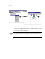
9.2.2 Adding a station.......................................................................................... 9-5
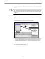
9.2.3 Opening the hardware configuration .......................................................... 9-6
9.2.4 Adding a rack.............................................................................................. 9-7
9.2.5 S7-300 rack ................................................................................................ 9-8
9.2.6 Adding the power supply module ............................................................... 9-8
9.2.7 Adding the CPU module ...........................................................................9-10
9.2.8 CPU’s DP port setting............................................................................... 9-11
9.2.9 Adding a PROFIBUS-DP node.................................................................9-13
9.2.10 DP slave (ET200) construction and addressing .....................................9-14
9.2.11 Adding the SM module ...........................................................................9-15
9.2.12 Connecting the racks (interface)............................................................. 9-16
9.2.13 Saving the hardware configuration .........................................................9-17
9.2.14 Downloading the hardware configuration ...............................................9-18
vii
Table of Contents
9.3 Uploading hardware configuration ............................................ 9-20
9.3.1 Uploading hardware configuration (1) ...................................................... 9-20
9.3.2 Uploading hardware configuration (2) ...................................................... 9-21
9.3.3 List of addresses ...................................................................................... 9-23
Part 4 Setting up and maintenance
Chapter 10 Overview of System ..................................10-1
10.1 Screen operation .................................................................... 10-2
10.1.1 Basic concept ......................................................................................... 10-2
10.1.2 Basic operation....................................................................................... 10-3
10.2 MD components...................................................................... 10-5
Chapter 11 Drive Parameter Screen............................11-1
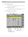
11.1 Drive Parameter Screen Operation......................................... 11-2
11.1.1 Startup .................................................................................................... 11-2
11.1.2 Screen Configuration .............................................................................. 11-3
11.1.3 Operation method ................................................................................... 11-4
11.1.4 Conditions for the modified parameters to be effective .......................... 11-7
11.1.5 Protection level ....................................................................................... 11-7
11.2 Drive Diagnosis Function ........................................................ 11-8
11.2.1 Drive diagnosis screen initiation ............................................................. 11-8
11.2.2 Drive diagnosis screen configuration...................................................... 11-8
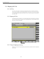
11.3 Mapping ACC file .................................................................. 11-10
11.3.1 ACC file................................................................................................. 11-10
11.3.2 Mapping ACC file.................................................................................. 11-10
11.3.3 Timing of mapping processing .............................................................. 11-10
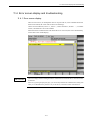
11.4 Error screen display and troubleshooting...............................11-11
11.4.1 Error screen display.............................................................................. 11-11
11.4.2 Troubleshooting .................................................................................... 11-12
11.4.3 Indication of parameter whose value can not be read .......................... 11-12
11.4.4 Error message display .......................................................................... 11-12
viii
Table of Contents
Chapter 12 How to use Digital Operation ....................12-1
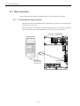
12.1 Basic operation........................................................................12-2
12.1.1 Connecting the digital operator...............................................................12-2
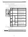
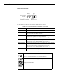
12.1.2 Function of digital operator .....................................................................12-3
12.1.3 Reset of servo alarm .............................................................................. 12-3
12.1.4 Switching the basic mode.......................................................................12-4
12.1.5 Axis selection mode................................................................................12-5
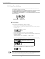
12.1.6 Status display mode ...............................................................................12-5
12.1.7 User Constant Setting Mode ..................................................................12-8
12.1.8 Operation on the monitor mode............................................................12-12
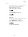
12.2 Application.............................................................................12-17
12.2.1 Alarm Trace Back Mode .......................................................................12-18
12.2.2 Clearing the alarm trace back data.......................................................12-19
12.2.3 Checking the motor type.......................................................................12-20
12.2.4 Checking the software version .............................................................12-22
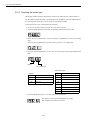
12.2.5 Origin searching mode .........................................................................12-23
12.2.6 Initializing the user constant setting value ............................................12-24
12.2.7 Manual zero adjustment and gain adjustment for analogue
monitor output ......................................................................................12-25
12.2.8 Motor current detection signal offset adjustment..................................12-28
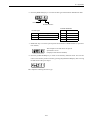
12.2.9 Setting the password (setting for write prohibit) ...................................12-30
Chapter 13 Drive system overview 1 ..........................13-1
13.1 System configuration...............................................................13-2
13.2 Specification of machine data and parameters .......................13-3
13.2.1 Structures of machine data and parameters ..........................................13-3
13.2.2 How to control machine data and parameters........................................13-4
13.2.3 Activation condition of machine data and parameters............................ 13-4
13.2.4 How to set machine data and parameters..............................................13-4
Chapter 14 Drive set-up procedure..............................14-1
14.1 Fundamental settings ..............................................................14-5
14.1.1 Control cycle...........................................................................................14-5
14.1.2 NCK processing capability......................................................................14-6
14.1.3 Servo control method and fundamental operation..................................14-6
14.1.4 Axis configuration ...................................................................................14-8
14.1.5 Motor encoder ......................................................................................14-14
14.1.6 External encoder .................................................................................. 14-20
14.1.7 Maximum number of motor revolutions ................................................ 14-30
14.1.8 Various mask settings...........................................................................14-31
14.1.9 Software version number check ........................................................... 14-32
14.1.10 Parameter initialization .......................................................................14-34
14.1.11 Alarm display ......................................................................................14-34
ix
Table of Contents
14.2 Servo control......................................................................... 14-36
14.2.1 Position control..................................................................................... 14-36
14.2.2 Speed control ....................................................................................... 14-38
14.2.3 Spindle servo mode.............................................................................. 14-39
14.2.4 Backlash compensation........................................................................ 14-40
14.2.5 Quadrant error compensation............................................................... 14-40
14.2.6 Torque reference notch filter................................................................. 14-43
14.2.7 Speed feedback compensation ............................................................ 14-44
14.2.8 Predictive control .................................................................................. 14-45
14.2.9 Model following control ......................................................................... 14-47
14.2.10 Stop vibration suppression ................................................................. 14-49
14.2.11 Vibration-damping control................................................................... 14-50
14.2.12 Gain switching .................................................................................... 14-52
14.2.13 Current offset adjustment ................................................................... 14-54
14.2.14 Analog monitor ................................................................................... 14-55
14.3 Motion Control ...................................................................... 14-57
14.3.1 Feed Rate............................................................................................. 14-57
14.3.2 Acceleration/Deceleration..................................................................... 14-59
14.3.3 Positioning ............................................................................................ 14-63
14.3.4 Emergency stop ................................................................................... 14-65
14.3.5 Return to reference point...................................................................... 14-68
14.3.6 Brake control ........................................................................................ 14-72
14.3.7 Speed feedforward ............................................................................... 14-73
14.3.8 Torque Control and Fixed Stop Function.............................................. 14-74
14.3.9 Absolute value detection ...................................................................... 14-78
14.3.10 Gantry control..................................................................................... 14-80
14.3.11 Collision detection............................................................................... 14-83
14.3.12 Spindle sequence I/O signals............................................................. 14-85
14.3.13 Spindle orientation.............................................................................. 14-87
14.3.14 Spindle winding changing................................................................... 14-90
14.3.15 Spindle gear changing and Spindle integrated with C axis control..... 14-92
14.3.16 Rigid tap ............................................................................................. 14-93
14.3.17 Threading ........................................................................................... 14-94
14.3.18 Spindle synchronization control.......................................................... 14-94
14.3.19 Skip Function...................................................................................... 14-96
14.4 High-speed High-accuracy Cutting ....................................... 14-97
14.4.1 Multi-block look-ahead.......................................................................... 14-97
14.4.2 Block compression ............................................................................... 14-98
14.4.3 Spline interpolation............................................................................. 14-100
14.4.4 Examples of machine data setting...................................................... 14-102
x
Table of Contents
14.5 Relevant Machine Data and Parameters ............................14-103
14.5.1 CNC relevant machine data ............................................................... 14-103
14.5.2 Servo drive relevant parameter ..........................................................14-107
14.5.3 Spindle relevant parameter and Servo drive relevant parameter ....... 14-110
14.6 Trouble shooting.................................................................. 14-112
14.6.1 Table of causes/countermeasures for troubles................................... 14-112
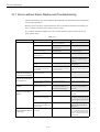
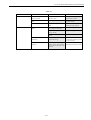
Chapter 15 Error and Troubleshooting ........................15-1
15.1 Errors without Alarm Display and Troubleshooting .................15-2
Chapter 16 Maintenance and Check ...........................16-1
16.1 Checking Servo motor and SERVOPACK...............................16-2
16.1.1 Checking Servo motor ............................................................................16-2
16.1.2 Checking SERVOPACK .........................................................................16-3
16.2 Checking Spindle motors and Invertors ..................................16-4
16.2.1 Items to be checked daily .......................................................................16-4
16.2.2 Scheduled maintenance .........................................................................16-5
16.2.3 Megger test on Spindle motor ................................................................16-5
16.2.4 Periodical check .....................................................................................16-6
16.3 Absolute encoder ....................................................................16-8
16.3.1 Replacing a battery in the Absolute encoder..........................................16-8
16.3.2 Handling a battery ..................................................................................16-8
16.3.3 Setting up (Initializing) Absolute encoder ...............................................16-9
16.4 Analogue monitor .................................................................. 16-11
Appendix Drive data list ................................................ A-1
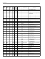
Appendix A Parameters .................................................................. A-2
A.1 Servo unit parameter list .............................................................................. A-2
A.2 List of Servo unit parameter switches .......................................................... A-8
A.3 List of Inverter parameter ........................................................................... A-13
A.4 List of parameters common to all drives .................................................... A-20
Appendix B Alarm/monitor data...................................................... A-23
B.1 List of Servo unit alarms............................................................................. A-23
B.2 List of Inverter alarms................................................................................. A-25
B.3 List of Servo unit monitor data ................................................................... A-27
B.4 List of Inverter monitor data ....................................................................... A-28
xi
Outline of this manual
Outline of this manual
■ This manual is a handy book for use by those who are familiar with the NC machine
tool Yaskawa Siemens YS 840DI (hereafter called YS 840DI) and are responsible
for its operation, maintenance or setup.
■ As a handy book, this manual may not contain basic information or technical details.
For such basic or detailed information, refer to the related manuals as listed below.
Related manuals
■ Related manuals are listed below, which you should read as necessary along with
this manual.
■ Read all related manuals to grasp the specifications and any usage constraints of
the control/operation panels before attempting to operate them.
Manuals
Yaskawa Siemens YS 840DI Operating Manual
Manual No.
NCSIE-SP02-04
Yaskawa Siemens YS 840DI Maintenance Manual
NCSIE-SP02-10
Yaskawa Siemens YS 840DI Maintenance Manual Serviceman Handbook (this manual)
NCSIE-SP02-19
Yaskawa Siemens YS 840DI Programming Manual for Machining Center
NCSIE-SP02-20
Yaskawa Siemens YS 840DI Programming Manual for Programming Lathe
NCSIE-SP02-21
xii
How to use this manual
How to use this manual
■ Target group
This manual is intended for those who are responsible for:
• manufacturing, inspection, trial run and tuning, or servicing of YS 840DI control panels, operation
panels, and other related units and devices.
■ Low-active signals
In this manual, low-active signals are indicated by the slash symbol (/) followed by their
name. For example:
• /S-ON for a low-active signal of S-ON
• /P-ON for a low-active signal of P-ON
Trademarks
• Windows and Windows NT are trademarks of Microsoft Corporation of the U.S.A.
• Ethernet is a trademark of Xerox Corporation of the U.S.A.
xiii
Safety precautions
Safety precautions
Listed below are important safety precautions that you must always follow when using the
product. Read and fully understand this manual and other related manuals before attempting
to install, operate, maintain, or service the product. The safety precautions and the
knowledge of the product are indispensable for the safety of yourself and the product.
■ Handling
CAUTION
• When handling the product, do not hold it by the cables.
Otherwise injury or damage could result.
• After installing the product on the machine, remove the eyebolts from the
product, and attach ordinary bolts of the same size in place of them to
close the eyebolt openings.
Otherwise damage could result.
PROHIBITED
• Do not handle the product in such places where it could get wet from rain
or water drops, or where harmful gas or liquid is present.
Otherwise injury or damage could result.
■ Storing
PROHIBITED
• Do not store the product in such places where they could get wet from rain
or water drops, or where harmful gas or liquid is present.
Otherwise damage could result.
• Do not let the packaged product fall from heights more than 60 cm.
Otherwise damage could result.
xiv
Safety precautions
MANDATORY
• Store the product in an indoor clean place satisfying the environmental
requirements.
Otherwise damage could result.
The environmental requirements:
• Ambient temperature: -20 to +60 ℃
• Relative humidity: 10 to 90%
• Altitude: 1000 m or lower
■ Installing
CAUTION
• Install the product such that its air intake or discharge opening is not
blocked by a wall or other objects and that foreign matter would not get
into the opening.
Otherwise a fire or damage could result.
• When installing, take care not to subject the product to a strong shock.
Otherwise damage could result.
• The electric power supplied to the product must be sufficient satisfying its
power requirements.
Otherwise malfunction could result.
• The power requirements of the 24 VDC external power supply unit supplying input/output contacts depend on the number of the contacts they supply.
If necessary to provide enough power, install an additional external power supply
unit.
• The motors have their flanges and shaft ends coated with rustproof agent.
Remove the agent with a cloth before installing the motors.
• When coupling a motor with a machine, well align the motor with the
machine.
Failing to do so could cause vibration, resulting in injury or damage.
xv
Safety precautions
CAUTION
• Observe the following when designing or installing enclosures (a poorly
designed or installed enclosure for a high-voltage unit could result in damage or malfunction):
• The enclosures must be of hermetic seal type.
• The average temperature rise of the product must be not more than 10 ℃ .
• Air stirring fans must be installed within the enclosures to improve cooling
efficiency and prevent local heat buildup (fans should be UL certified).
• Sealing to close cable inlet holes and doors must be effective.
• Displays tend to collect airborne dust and thus malfunction. Therefore their
enclosures must be so designed as to prevent dust intrusion.
• CNC and other units as well as PC boards could malfunction due to accumulated dust. Therefore their enclosures must be so designed as to prevent dust
intrusion.
• Packing must be provided so that cable inlet holes, doors, and back plates are
fully closed.
• Observe the following when installing the units (poorly installed units could
result in damage or malfunction):
• The servo units must be fixed upright using screws or bolts.
• The servo units must be provided with enough space over and under them to
allow them to effectively dissipate their heat.
• Install a servo unit in an enclosure such that the heat sink fins of the unit come
out of the enclosure to keep the unit’s internal temperature lower. The exposed
heat sink fins must be subjected to a 2.5 m/s air draft.
• If an air stirring fan is installed inside an enclosure, the fan must be oriented
such that the air does not directly hit a servo unit (to prevent the servo unit
from collecting more dust).
• Units must be installed such that inspection, replacement and other servicing
activities are easy.
• Do not operate the system if any inverter or converter is physically broken
or otherwise damaged.
Otherwise injury could result.
• When handling the units, hold them by the mounting base, not by the front
cover.
If you hold them by the front cover, the main body could come off the front cover
and might drop onto and injure your foot.
Mount the units to a metal or other non-flammable structure. Otherwise, a fire
could result.
• The maximum operating temperature of 55 ℃ must not be exceeded. The
air draft hitting the heat sink must be at not more than 45 ℃ .
Note that overheat could result in a burn or a fire.
• An external emergency stop circuit must be provided so that operation
can be stopped and power shut off immediately.
Be aware of a risk of injury.
xvi
Safety precautions
■ Wiring
WARNING
• Shut off power to the product before attempting to work on it.
Otherwise electric shock or a fire could result.
• Wiring work must be done only by qualified personnel.
Otherwise electric shock or a fire could result.
• After wiring work for completing an emergency stop circuit, always check
the circuit for functionality. The customer is responsible for the wiring
work.
Be aware of a risk of injury.
• The grounding terminals
must be grounded properly.
Otherwise electric shock or a fire could result.
CAUTION
• Wiring work must be duly done by qualified personnel.
Otherwise electric shock, a fire, or malfunction could result.
• Never apply an AC three-phase power to the U, V, and W output terminals
on a SERVOPACK powering a servo motor.
Otherwise the SERVOPACK would be damaged.
• The capacity and wiring size of customer’s power supply must be so
selected as to satisfy the specific operating conditions and required
capacity. Note that the actual capacity of a cable decreases significantly if
the ambient temperature exceeds 30 ℃ . Determine a correct cable size
according to applicable electrical installation regulations and the technical
specifications issued by the cable manufacturer.
Use of a cable of incorrect size could result in a fire.
• Signal cables must be of twist pair, twist-pair multi-strand, or shielded
twist-pair multi-strand type. If a type is specified for signal cables in this
manual, that type must always be used.
Otherwise malfunction could result.
• Cables must be so routed as to be as short as possible.
Otherwise malfunction could result.
• Input or output signal cables must not be bundled together with power
cables or routed in the same wiring duct with power cables inside or outside the panels.
Properly separating signal cables from power cables reduces the effect of electric
noise from the power cables on the signal cables.
If electric noise comes into the product along the power line, install a noise filter
at the panel.
xvii
Safety precautions
CAUTION
• For information on the required capacity and other specifications of a
noise filter, see the General Documentation - Hardware.
A properly selected noise filter can reduce conducted electric noise significantly.
• Provide the last SERVOPACK module with a terminating connector.
Otherwise malfunction could result.
• Ensure that the voltage of the AC power supply to a converter is equal to
the rated voltage of that converter.
Otherwise injury or a fire could result.
• Do not subject the inverters or converters to a high-voltage withstanding
test.
Otherwise their semiconductor components would be damaged.
• Wiring to the inverters or converters must be done according to the relevant wiring drawing.
Otherwise they could be damaged.
• The screws of a terminal block must be tightened to a specified torque.
Otherwise a fire could result.
• Never connect an AC main power supply to the U/T1, V/T2, and W/T3 output terminals.
Otherwise the inverter would be damaged.
xviii
Safety precautions
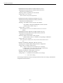
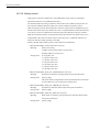
MANDATORY
• The grounding wire from each unit must be connected to the enclosure or
the grounding plate directly.
Example grounding wiring
S.V
200 VAC
U
LF
M
V
W
CN
CN
E
PG
E
Enclosure
Operation relay
sequence
LF
AVR
Single-point grounding
(Ground resistance 100 Ωor less)
• Wires for grounding must be in accordance with applicable electrical
installation regulations and the internal wiring rules.
• The grounding terminal of a servo motor must be wired to the grounding
terminal of the corresponding SERVOPACK.
• All wires to be grounded must be directly connected to a single point that
is class-D or better grounded.
Otherwise electric shock, a fire, or malfunction could result.
• The single grounding point for the product must not be used to also
ground a power device.
Otherwise malfunction could result.
xix
Safety precautions
■ Operating
WARNING
• Do not touch live units or terminals.
Otherwise electric shock or malfunction could result.
• Do not touch any current-carrying parts even if you have shut off power to
them, until at least 5 minutes have passed (to let any residual charge go
out).
Otherwise electric shock or malfunction could result.
• Take care not to damage, pull on, or pinch the cables.
Otherwise electric shock could result.
• Do not touch any rotating parts before you shut off power to them.
Otherwise injury could result.
• Never attempt to modify the product.
Otherwise electric shock, a fire, or damage could result.
• Close the upper and lower covers before switching on the input power.
Otherwise electric shock could result.
• Provide an additional emergency stop button outside the product.
This is a necessary safety precaution.
CAUTION
• Ensure that the environmental requirements are fully met.
A fire, electric shock, or malfunction could result if the product were operated in
excessively hot, humid, dusty, corrosive, vibration-, or shock-ridden conditions.
The environmental requirements are these:
• The atmosphere must be free of corrosive gas or vapor.
• There must be no risk of being splashed with machining oil or organic solvent.
• The relative humidity must be between 10 and 90%RH with no dew.
• The ambient temperature around the control panels must be between 5 and
30℃. The control panels must be protected from freezing, direct sunlight, heat
sources, or the elements.
• Floor vibration must not be more than 4.9 m/s2.
• Take care so that no wire chips or other foreign matter would enter the
product.
Otherwise a fire, damage, or malfunction could result.
• When using the programming functions, always follow the instructions
given in the relevant manuals.
Otherwise injury or malfunction could result.
xx
Safety precautions
CAUTION
• Do not touch the heat sinks, as they can get very hot.
Otherwise a burn could result.
• Confirm that the speed limits of the motors are compatible with the
inverter settings before operation.
Otherwise injury could result.
• Do not measure the signal voltages during operation.
Otherwise damage could result.
• The inverters are already set at the factory. Do not change the settings
unless you know exactly what you are doing.
Otherwise damage could result.
MANDATORY
• When switching on the main power, ensure that at least 2 seconds have
elapsed after the last switching-off operation.
Otherwise malfunction could result.
PROHIBITED
• Never attempt to disassemble or modify the units or devices in the panels.
Otherwise a fire, damage, or malfunction could result.
• Do not tamper with the settings of the rheostats or other devices of the
control panels.
Otherwise a fire, damage, or malfunction could result.
xxi
Safety precautions
■ Maintaining
WARNING
• Do not touch the terminals of the inverters or converters, as some of them
are at high voltage and very dangerous.
Otherwise electric shock could result.
• Do not leave the upper or lower cover open when the panel is energized.
Always turn off the circuit breaker before opening the covers.
Otherwise electric shock could result.
• Confirm that the main power and the control power are switched off and
the CHARGE lamp is not lit before starting maintenance work.
Be aware that capacitors can have a high voltage charge for a while even after the
circuit breaker is switched off.
• Only qualified personnel may perform maintenance or service work.
Otherwise electric shock could result.
CAUTION
• When handling the control PC boards, take necessary measure to prevent
their CMOS ICs from being damaged from electrostatic discharge.
Do not touch the CMOS ICs. Otherwise they could be damaged.
• Never attempt to change wiring connections, or engage or disengage connectors while they are energized.
Otherwise injury could result.
■ Others
WARNING
• Never attempt to modify the product.
Otherwise electric shock or injury could result.
xxii
Safety precautions
■ General notes
Notes on the usage of this manual
• Illustrations and drawings in this manual may show parts with their cover or
safety shield removed so that inside details can be seen. Regardless of the
drawings, the products must always be operated according to the manual with
all the covers and shields installed in place.
• Illustrations and photos in this manual represent typical configurations, and
may not exactly represent the products delivered.
• This manual is subject to change to reflect modification or specification change
to the product or to make it easier to read. An updated document No. means a
new version of this manual.
• If you need additional copies of this manual to replace damaged or lost ones or
otherwise, please order from the nearest sales office indicated on the back
cover referring to the document No. printed on the front cover of this manual.
• If the nameplate on the products is defaced or damaged, order a new one from
your dealer or the nearest sales office indicated on the back cover of this manual.
• Yaskawa Siemens would not guarantee the quality of the product modified by
the customer. Yaskawa Siemens is not responsible for any injury or damage
due to the product modified by the customer.
xxiii
Warning labels
Warning labels
Warning labels are attached to the product to draw special attention. Always follow the
instructions. The locations and meanings of the warning labels are as follows:
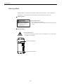
■ Warning label 1
危険 WARNING
けが感電のおそれがあります,
Risk of electric shock.
・据付け,運転の前には必ず取扱説明書をお読み下さい。
・通電中及び電源遮断後5付以内は端子部に触らないで
下さい。
・Read manual before installing.
・Wait 5 minutes for capacitor discharge after
disconnecting power supply.
Risk of electric shock
• Read manual before installing.
• Wait 5 minutes for capacitor discharge after disconnecting power
supply.
■ Warning label 2
Risk of electric shock
• Do not touch the terminals while the product is switched on or for 5 minutes after
the product is switched off.
SERVOPACK
200V
YASKAWA
SERVOPACK
SGDK-75AEA
200V
Position of warning label 1
CN5
A/B
SW1
CHARGE
RDY
CN1
CN6
CN2
Position of warning label 2
xxiv
Warning labels
■ Warning marking
Ground the unit by connecting a grounding wire to this grounding terminal.
SERVOPACK
200V
YASKAWA
SERVOPACK
SGDK-75AEA
200V
CN5
A/B
SW1
CHARGE
RDY
CN1
CN6
CN2
Position of warning marking 2
xxv
Part 1
Hardware
Chapter 1
System Configuration
1.1 System configuration - - - - - - - - - - - - - - - - - - - - - - - - - - - - - 1-2
1.1.1 General wiring drawing - - - - - - - - - - - - - - - - - - - - - - - - - - - - - - - - - - 1-2
1.1.2 List of system components - - - - - - - - - - - - - - - - - - - - - - - - - - - - - - - 1-4
1.2 Meanings of component designations - - - - - - - - - - - - - - - - - 1-8
1.2.1 SERVOPACK designations - - - - - - - - - - - - - - - - - - - - - - - - - - - - - - - 1-8
1.2.2 Servo motor designations - - - - - - - - - - - - - - - - - - - - - - - - - - - - - - - 1-10
1.2.3 Spindle motor designations - - - - - - - - - - - - - - - - - - - - - - - - - - - - - - 1-11
1-1
System Configuration
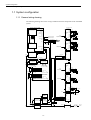
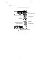
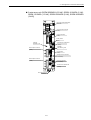
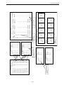
1.1.1 General wiring drawing
1.1 System configuration
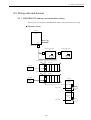
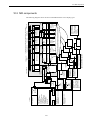
1.1.1 General wiring drawing
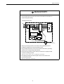
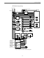
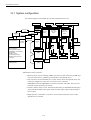
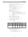
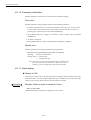
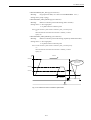
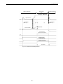
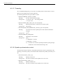
The following drawing shows how wiring is made between the components of the YS 840DI
system:
Terminating connector
Yaskawa Siemens 840DI
Operation panel unit (color LCD)
OP10FS(Standard type)
OP10FT(Touch-panel type)
CN7B CN5B
CNC Unit PCU50
PN
CN28
POWER
Ethernet
CN22
PG(Serial)
PS/2 MOUSE
CN24
Servo unit
(2-axis servo)
SGDK-
PG(Pulse)
PS/2 Keyboard
USB
USB
VGA
IO-USB Cable
COM1(25pin)
RS232C(D-sub25pin)
COM2(9pin)
RS232C(D-sub9pin)
Display cable
Keyboard cable
LPT1
CN1
PN
PC
CARD
Emergency stop (input)
X101
X111
POWER
CN12
PG(Serial)
CN14
PG(Pulse)
Braking circuit for
the 3rd and 4th axes
24 VDC
5th motor
Separately
mounted PG
CN7B CN5B
PN
CN28
POWER
CN22
PG(Serial)
CN24
Servo unit
(2-axis servo)
SGDK-
PG(Pulse)
HNDLE PG
NC ready (output)
X1(24 VDC IN)
CN18
CN7A CN5A
PC card drive
24 VDC
X121
NC keyboard
Attached to OP10F□
Direct IN
Braking circuit for the
5th and 6th axes
6th motor
Separately
mounted PG
CN1
PROFIBUS-DP
PN
MPI
4th motor
Separately
mounted PG
CN18
POWER
CN12
PG(Serial)
CN14
PG(Pulse)
CN7A CN5A
3rd motor
Separately
mounted PG
CN7B CN5B
Machine operation panel
OP032S
X20
PN
MPI
Converter
CIMRMRXN
24 VDC
PROFIBUS-DP
X10
Emergency stop/start
condition
PROFIBUS-DP
A1,A2
L1,L2,L3
Machine panel I/O module
Machine panel I/O module
X2 PP Module
X1
200 VAC
PROFIBUS-DP
CN9
CN1
200 VAC
24 VDC
X333 X222 X111
CN5A
X2 PP Module
Terminating connector
X1
Terminating connector
X333 X222 X111
CN7B CN5B
PN
Machine operation panel
input/output
24 VDC
PROFIBUS-DP
I/O module
24 VDC
Servo unit
(1-axis servo)
SGDK-
* From external power supply
PS307
Direct IN
Braking circuit for
the 2nd axes
200 VAC
I/O module
PS307
I/O module
power supply
PN
24 VDC Machine input/
output
24
VDC
24
VDC
CN1
POWER
CN2
PG(Serial)
CN4
PG(Pulse)
CN7A CN5A
2nd motor
Separately
mounted PG
* From external power supply
CN7B CN5B
Digital I/O module
(6ES7321/322/323)
PN
Servo unit
(1-axis servo)
SGDKCN8
24 VDC Machine input/
output
Interface module(ET200M)
PROFIBUS-DP
CN8
Braking circuit for
the 1st axes
* From external power supply
CN1
PN
POWER
CN2
PG(Serial)
CN4
PG(Pulse)
1st motor
CN7A CN5A
Separately
mounted PG
CN7B CN5B
PN
Inverter
CIMRMXN
U,V,W,E
CN1
CN4
CN2
PN
POWER
PG(Pulse or
separately mounted)
PG(Serial)
Spindle motor
CN7A CN5A
Bus bar
CN7B CN5B
PN
Power backup
battery
UPS BATTERY
PROFIBUS-DP
Emergency stop/start
condition
200 VAC
Power module
PS module 10
24 VDC
Power backup
24 VDC
module
UPS module 10
Bat
* Machine input/output
24 VDC
External power
supply
Converter
CIMRMRXN
CN9
Terminating
connector
Interface cable
Control power cable
CN1
200 VAC
200 VAC
A1,A2
L1,L2,L3
CN5A
Terminating connector
Reactor
SVM
Circuit breaker
200 VAC
200 VAC
1-2
Line filter
200 VAC
50/60Hz
1.1 System configuration
INFO
Notes on the general wiring drawing
• Number of axes of the YS 840DI system:
The maximum number of axes of the system is seven (including the spindle) per converter.
• External power supply:
An external power supply of appropriate capacity must be provided by the customer.
• Separately mounted encoder:
Separately mounted encoders are optional for any servo unit or inverter.
• Emergency stop/start circuit:
An emergency stop/start circuit must be provided for each converter. Thus a system with two converters requires two separate emergency stop/start circuits.
• Braking circuit:
A braking circuit may be provided only for an axis that needs it.
• Direct IN circuit:
A direct IN circuit must be provided for each converter system. The direct IN circuit may be connected to any servo unit of the converter system.
1-3
System Configuration
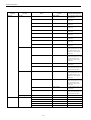
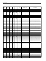
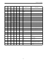
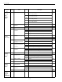
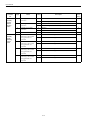
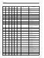
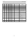
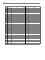
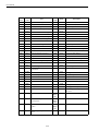
1.1.2 List of system components
1.1.2 List of system components
The following table lists the components of the YS 840DI system:
Category
YS 840DI
Function
Designation/Catalog
number
Name
Specifications/Remarks
CNC unit
PCU50
6FC5220-0AB00-1AA0
Operation panel
OP010FS
6FC5203-0AF10-0AA0
Standard type
OP010FT
6FC5203-0AF11-0AA0
Touch panel type
NC keyboard
OP010F □
−
Attached to operation panel
Machine control
panel
Machine control panel
OP032S
6FC5203-0AD10-1AA
Optional
PC card drive
PC card drive
PCMCIA extension card slot from
PCU50 parallel port
6FC5235-0AA06-0AA0
Optional
I/O module
Machine control panel
I/O
PP module
6FC5611-0CA01-0AA0
72 inputs/48 outputs
Interface module
ET200M
6ES7153-1AA03-0XB0
I/O power supply
module
PS307(2A)
6ES7307-1BA00-0AA0
2 A output at 24 VDC
PS307(5A)
6ES7307-1EA00-0AA0
5 A output at 24 VDC
PS307(10A)
6ES7307-1KA00-0AA0
10 A output at 24 VDC
SM321(DI32 × 24 VDC)
6ES7321-1BL00-0AA0
32 inputs at 24 VDC
SM321(DI16 × 24 VDC)
6ES7321-1BH00-0AA0
16 inputs at 24 VDC
SM321 (DI16 × 24 VDC source)
6ES7321-1BH50-0AA0
16 inputs at 24 VDC source
SM321(DI16 × 120 VAC)
6ES7321-1EH01-0AA0
16 inputs at 120 VAC
SM321(DI8 × 120/230 VAC)
6ES7321-1FF01-0AA0
8 inputs at 120/230 VAC
SM322(DO32 × 24 VDC/0.5A)
6ES7322-1BL00-0AA0
32 outputs at 24 VDC/0.5 A
SM322(DO16 × 24 VDC/0.5A)
6ES7322-1BH00-0AA0
16 outputs at 24 VDC/0.5 A
SM322(DO8 × 24 VDC/2A)
6ES7322-1BF01-0AA0
8 outputs at 24 VDC/2 A
SM322(DO16 × 120VAC/1A)
6ES7322-1EH01-0AA0
16 outputs at 120 VAC/1 A
SM322(DO8 × 120/230VAC/2A)
6ES7322-1FF01-0AA0
8 outputs at 120/230 VAC/2
A
SM323
(DI16/DO16 × 24VDC/0.5A)
6ES7323-1BL00-0AA0
16 inputs at 24 VDC,
16 outputs at 24 VDC/0.5 A
SM323(DI8/DO8 × 24 VDC/0.5A)
6ES7323-1BH00-0AA0
8 inputs at 24 VDC,
8 outputs at 24 VDC/0.5 A
SM323 (DO16 × 120 VAC relay)
6ES7322-1HH00-0AA0
16 relay outputs at 120 VAC
SM323 (DO8 × 230 VAC relay)
6ES7322-1HF00-0AA0
16 relay outputs at 230 VAC
Digital input module
Digital output module
Digital I/O module
Relay output module
Power supply
module
SERVOPACK
Dummy module
DM307
6ES7370-0AA01-0AA0
Dummy module
Power supply module
PS module 10
6ES1334-2BA00
24 VDC/10 A output
Power supply backup
module
UPS module 10
6EP1931-2EC01
24 VDC/10 A output
Power supply backup
battery
UPS BATTERY
6EP1935-6MD11
3.2A/h
Converter
45 kW converter
CIMR-MRXN20455A
37 kW converter
CIMR-MRXN20375A
30 kW converter
CIMR-MRXN20305A
22 kW converter
CIMR-MRXN20225A
1-4
1.1 System configuration
Category
SERVOPACK
(continued)
Function
Converter
Inverter
18.5 kW converter
15 kW converter
CIMR-MRXN20155A
11 kW converter
CIMR-MRXN20115A
7.5 kW converter
CIMR-MRXN27P55A
5.5 kW converter
CIMR-MRXN25P55A
3.7 kW converter
CIMR-MRXN23P75A
37 kW inverter
CIMR-MXN20375A
30 kW inverter
CIMR-MXN20305A
22 kW inverter
CIMR-MXN20225A
CIMR-MXN20185A
15 kW inverter
CIMR-MXN20155A
11 kW inverter
CIMR-MXN20115A
7.5 kW inverter
CIMR-MXN27P55A
5.5 kW inverter
CIMR-MXN25P55A
3.7 kW inverter
CIMR-MXN23P75A
0.5 kW servo unit
SGDK-05AEA
1 kW servo unit
SGDK-10AEA
1.5 kW servo unit
SGDK-15AEA
2 kW servo unit
SGDK-20AEA
3 kW servo unit
SGDK-30AEA
5 kW servo unit
SGDK-50AEA
6 kW servo unit
SGDK-60AEA
7.5 kW servo unit
SGDK-75AEA
0.5 kW × 2 servo units
SGDK-0505AEA
1 kW × 2 servo units
SGDK-1010AEA
1.5 kW × 2 servo units
SGDK-1515AEA
2 kW × 2 servo units
SGDK-2020AEA
3 kW × 2 servo units
SGDK-3030AEA
Optional unit
PC board for separately mounted PG
SGDK-CF01A
Spindle motor
5.5kW
MX □□□ -06AS □□□
7.5kW
MX □□□ -08AS □□□
11kW
MX □□□ -11AS □□□
15kW
MX □□□ -15AS □□□
18.5kW
MX □□□ -19AS □□□
22kW
MX □□□ -22AS □□□
30kW
MX □□□ -30AS □□□
0.45 kW servo motor
SGMKS-05A □□□□
2-axis servo unit
Servo motor
Specifications/Remarks
CIMR-MRXN20185A
18.5 kW inverter
1-axis servo unit
Motor
Designation/Catalog
number
Name
0.85 kW servo motor
SGMKS-09A □□□□
1.3 kW servo motor
SGMKS-13A □□□□
1.8 kW servo motor
SGMKS-20A □□□□
2.9 kW servo motor
SGMKS-30A □□□□
4.4 kW servo motor
SGMKS-44A □□□□
5.5 kW servo motor
SGMKS-55A □□□□
7.5 kW servo motor
SGMKS-75A □□□□
1-5
Per axis
System Configuration
1.1.2 List of system components
Category
Bus bar
Function
Name
Bus bar
Local bus cable
Control power cable
AC reactor
Designation/Catalog
number
Specifications/Remarks
JZSP-CGB02-1
For connection inside a 250mm wide unit
JZSP-CGB02-2
Between 250- and 150-mm
wide units
JZSP-CGB02-4
Between 250- and 75-mm
wide units
JZSP-CGB02-3
Between 150- and 150-mm
wide units
JZSP-CGB02-5
Between 150- and 75-mm
wide units
JZSP-CGB02-6
Between 75- and 75-mm
wide units
JZSP-CGB02-7
Between 150- and 250-mm
wide units
JZSP-CGB02-8
Between 75- and 250-mm
wide units
JZSP-CGB02-9
Between 75- and 150-mm
wide units
JZSP-CNS90-1
Between 250- and 150-mm
wide units, between 150- and
150-mm wide units, and
between 75- and 150-mm
wide units
JZSP-CNS90-2
Between 250- and 75-mm
wide units, between 150- and
75-mm wide units, and
between 75- and 75-mm
wide units
JZSP-CNS90-4
1 m long between upper and
lower units
JZSP-CNS90-5
Between 150- and 250-mm
wide units, and between 75and 250-mm wide units
JZSP-CNB00-1
Between 250- and 150-mm
wide units, between 150- and
150-mm wide units, and
between 75- and 150-mm
wide units
JZSP-CNB00-2
Between 250- and 75-mm
wide units, between 150- and
75-mm wide units, and
between 75- and 75-mm
wide units
JZSP-CNB00-3
1 m long between upper and
lower units
JZSP-CNB00-4
Between 150- and 250-mm
wide units, and between 75and 250-mm wide units
Terminating connector
JZSP-CNS90-9
Reactor
UZBA-B150A 0.07mH
For a 45 kW converter
For a 37 kW converter
For a 30 kW converter
For a 22 kW converter
For a 18 kW converter
1-6
1.1 System configuration
Category
AC reactor
(continued)
Function
Designation/Catalog
number
Name
Reactor
Specifications/Remarks
For a 15 kW converter
For a 11 kW converter
For a 7.5 kW converter
For a 5.5 kW converter
For a 3.7 kW converter
PROFIBUS-DP
related
Others
PROFIBUS-DP
connector
Vertical-connection type connector
6ES7972-0B □ 11-0XA0
□ indicates whether a PG
port is available.
(A) means not available, and
(B) means available.
PROFIBUS-DP
connector
35-degree-connection type connector
6ES7972-0B □ 40-0XA0
□ indicates whether a PG
port is available.
(A) means not available, and
(B) means available.
PROFIBUS-DP
connector
Horizontal-connection type connector
6GK1500-0EA0
For a converter
PROFIBUS-DP cable
Stranded-wire cable
6XV1830-3EH10
Manual pulse
generator
Handle PG
OSM-01-2GA-15
Braking power supply
unit
BK unit
OPR-109A
For 200 VAC
OPR-109F
For 100 VAC
1-7
System Configuration
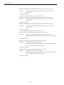
1.2.1 SERVOPACK designations
1.2 Meanings of component designations
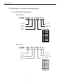
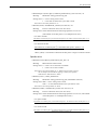
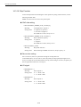
1.2.1 SERVOPACK designations
Converter
CIMR - MRX N 2 045 5 A
Series identifier
Revision symbol
Protection type
Specification
N:For NC systems
5:External cooling
Maximum output
Supply voltage
2:200 V
045
45kW
037
37kW
030
30kW
022
018
22kW
015
15kW
18kW
011
11kW
7P5
5P5
7.5kW
5.5kW
3P7
3.7kW
Inverter
CIMR - MX N 2 030 5 A
Revision symbol
Series identifier
Protection type
Specification
N:For NC systems
5:External cooling
Maximum output
Supply voltage
2:200 V
1-8
037
37kW
030
30kW
022
018
22kW
015
15kW
18kW
011
11kW
7P5
5P5
7.5kW
5.5kW
3P7
3.7kW
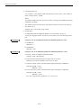
1.2 Meanings of component designations
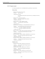
Servo unit
SGDK - 75 - A E A
or
3030
Series identifier
Communication command
(E only)
Supply voltage
A:2000 V
Rated output (see the table below)
1-axis unit
Basic specification(A only)
2-axis unit
Number
Capacity
Number
Capacity
0.5
0.5kW
0505
0.5kW
10
1kW
1010
1kW
15
1.5kW
1515
1.5kW
20
2kW
2020
2kW
30
3kW
3030
3kW
50
5kW
1.5kW
60
6kW
1.5kW
75
7.5kW
1.5kW
1-9
System Configuration
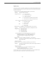
1.2.2 Servo motor designations
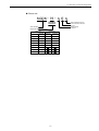
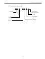
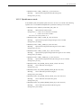
1.2.2 Servo motor designations
SGMKS - 05 A 2 A 2 S
Servo motor capacity ( kW)
Symbol
Brake and oil seal specifications
1: No brake nor oil seal
S: With oil seal
B: With 90 VDC brake
C: With 24 VDC brake
D: With oil seal, with 90 VDC brake
E: With oil seal, with 24 VDC brake
SGMKS
1500min -1
05
0.45
09
13
0.85
1.3
20
30
44
1.8
55
75
5.5
7.5
2.9
4.4
Shaft-end specification
SGMKS
Specification
Symbol
2
Straight, with no key
3
1/10 tapered, with a parallel key
◎
○
6
Straight, with a key and a tap
○
Design category
A: SGMKS (400% peak torque)
B: SGMKS (standard peak torque)
Serial encoder specification
Specification
Symbol
17-bit, absolute
3
C
20-bit, absolute
◎
○
17-bit incremental
○
Voltage
A : 200 V
1-10
SGMKS
2
1.2 Meanings of component designations
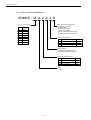
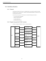
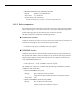
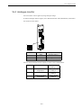
1.2.3 Spindle motor designations
UA K A - 30 A Z 1
Shaft-end specification
N: No key
Blank: With a key (standard)
AC spindle motor
Cooling method
K: Fully closed, forced air cooling
Mounting method
1: By flange
3: With feet
Winding type
A: Single winding (standard)
Encoder specification
Z: With an origin
N: No encoder
Design category
A: Standard
50% ED output
30: 30 kW
1-11
System Configuration
1.2.3 Spindle motor designations
1-12
Chapter 2
Installing the control panels
This chapter describes how to install the components of the YS 840DI system.
2.1 Designing the panels - - - - - - - - - - - - - - - - - - - - - - - - - - - - - 2-2
2.1.1 Environmental conditions for installing the control panels and
other system components - - - - - - - - - - - - - - - - - - - - - - - - - - - - - - - 2-2
2.1.2 Thermal design of the enclosures- - - - - - - - - - - - - - - - - - - - - - - - - - - 2-3
2.1.3 Heat dissipation - - - - - - - - - - - - - - - - - - - - - - - - - - - - - - - - - - - - - - - 2-6
2.1.4 Power consumption - - - - - - - - - - - - - - - - - - - - - - - - - - - - - - - - - - - - 2-8
2.2 Protecting against electric noise - - - - - - - - - - - - - - - - - - - - - 2-9
2.2.1 Separation of cables - - - - - - - - - - - - - - - - - - - - - - - - - - - - - - - - - - - - 2-9
2.2.2 Noise-proof devices - - - - - - - - - - - - - - - - - - - - - - - - - - - - - - - - - - - 2-10
2.2.3 Grounding - - - - - - - - - - - - - - - - - - - - - - - - - - - - - - - - - - - - - - - - - - 2-12
2.2.4 Cable shield clamp - - - - - - - - - - - - - - - - - - - - - - - - - - - - - - - - - - - - 2-13
2.3 Installation precautions - - - - - - - - - - - - - - - - - - - - - - - - - - - 2-14
2.3.1 Installing the CNC units- - - - - - - - - - - - - - - - - - - - - - - - - - - - - - - - - 2-14
2.3.2 Installing the feed/spindle SERVOPACK - - - - - - - - - - - - - - - - - - - - - 2-15
2.3.3 Orientation of and installation space for the SERVOPACK - - - - - - - - 2-16
2.3.4 Installation space for the I/O modules - - - - - - - - - - - - - - - - - - - - - - - 2-17
2.3.5 Installing lightning-surge absorbers - - - - - - - - - - - - - - - - - - - - - - - - 2-18
2-1
Installing the control panels
2.1.1 Environmental conditions for installing the control panels and other system components
2.1 Designing the panels
2.1.1 Environmental conditions for installing the control panels and other
system components
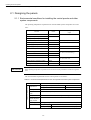
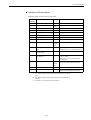
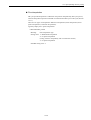
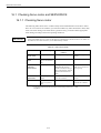
The operating temperature requirements for the YS 840DI system components are as follows:
Function
Allowable operating temperature
range
Name
CNC unit
PCU50
CNC operation panel (face)
OP010F □
5 - 45 ℃
CNC operation panel (back)
IMPORTANT
Machine control panel
OP032S
0 - 45 ℃ (face), 0 - 55 ℃ (back)
Power supply module
PS module
0 - 60 ℃
Power supply backup module
UPS module
Power supply backup battery
UPS battery
5 - 40 ℃
Machine control panel I/O
PP module
0 - 55 ℃
I/O power supply module
PS307
Interface module
ET200M
0 - 60 ℃ (horizontal mounting),
0 - 40 ℃ (vertical mounting)
I/O module
I/O module
SERVOPACK
SERVOPACK
0 - 55 ℃ ,
0 - 45 ℃ (heat sink)
Reactor/winding changeover switch
Reactor
0 - 60 ℃
Braking power supply unit
BK unit
0 - 60 ℃
If the operating temperature requirements were not observed, the performance could not be guaranteed.
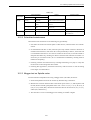
The environmental requirements for the control panels are as follows:
Table 2.1 Environmental requirements for the control panels and other system components
Items
Environmental conditions
Ambient
temperature *1
Requirements
During storage or transportation
-20 to +60 ℃
During operation
5-30 ℃ *2
Humidity
10-90% RH (with no dew)
Vibration and
shock
4.9 and 73.5 m/s2 respectively
Atmosphere
Without excessive airborne dust, machining oil mist, or organic solvent vapor
Power supply
module, I/O power
supply module
100 - 230 VAC 50/60Hz
Power supply
Input supply voltage: 100/200 VAC; Frequency: 50/60 Hz
Converter
Main power supply
200-230 VAC +10/-15%, 50/60 Hz ± 5%, three-phase
Control power supply
200-230 VAC +10/-15%, 50/60 Hz ± 5%, single-phase
2-2
2.1 Designing the panels
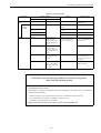
IMPORTANT
• Even if the ambient temperature requirement is met, the system must not be installed in such
places where it is exposed to direct sunlight, nearby heat sources, or the elements.
• The ambient temperature must be between 5 and 30℃ taking into account UPS battery’s operating
temperature requirement of 5-40 ℃ and the expected temperature rise of 10 ℃ .
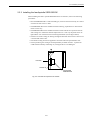
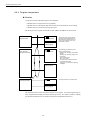
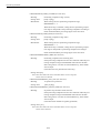
2.1.2 Thermal design of the enclosures
The enclosure of a panel must hermetically enclose a CNC or other unit and be so designed
as to keep the internal average temperature rise 10 ℃ or less.
Internal average temperature rise
The internal average temperature rise for a sheet metal enclosure can be calculated as follows:
• ΔT
: Internal temperature rise
(℃)
• P
: Internal heat produced
(W)
• qe
: Enclosure’s thermal transfer ratio
(W/ ℃ )
• k
: Sheet metal’s thermal transfer constant
(W/m2 ℃ )
• A
With an internal fan
6W m2 ℃
Without internal fan
4W/ m2 ℃
: Enclosure’s effective surface area (m2)
Note: Effective surface area means the area of an enclosure’s surface that
can dissipate heat
(excluding such a surface as is in contact with another object).
2-3
Installing the control panels
2.1.2 Thermal design of the enclosures
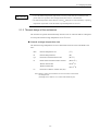
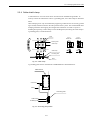
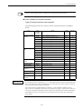
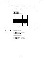
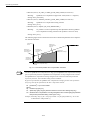
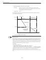
Internal temperature rise of a panel with an internal fan
The size of the enclosure is assumed 450 (W) × 790 (H) × 150 (D) mm.
790mm
EXAMPLE
450mm
150mm
• Effective surface area
A = 1.0155 (m2)
(the bottom surface is excluded as the panel is of stand-alone type)
• Internal heat produced
P = 60 (W)
• Internal temperature rise
△T =
60
P
P
=
=
= 9.8 (℃)
6×1.0155
qe
k・A
The calculated internal temperature rise ΔT = 9.8 ( ℃ ), thus the temperature rise requirement of 10 ℃ is satisfied.
If the temperature rise requirement is not satisfied, additional measure must be taken to
lower the temperature rise.
Capacity of heat exchangers
If an internal fan alone is not sufficient for satisfying the temperature rise requirement, a
heat exchanger must be installed (see the table below).
Table 2.2 Heat exchanger
Type
DE9404550-1
Designation
Capacity
REX1600ESYE
110W/10 ℃
Outside dimensions (mm)
194 : (W) 800 : (H) 65 : (D)
Note: Capacity means the amount of heat that a heat exchanger can remove,
on the ground that the temperature rise must be kept 10 ℃ or less.
Maximum internal heat that can be safely produced in a panel
equipped with a heat exchanger
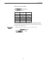
EXAMPLE
Up to 359 W of internal heat can be safely produced in a panel if it is equipped with a heat
exchanger of table 2.2, as shown below.
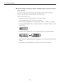
• P = k・A・△ T + 110W/10 ℃= 6 × 4.16 × 10 + 110 = 359W/10 ℃
2-4
2.1 Designing the panels
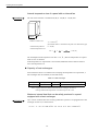
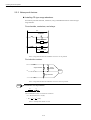
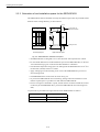
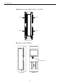
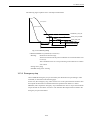
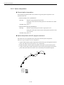
Installing a heat exchanger
It is the responsibility of the customer to prepare and install together an enclosure and a heat
exchanger. The internal fan must be mounted at an uppermost location so as to force the
internal air down. The external fan must be mounted at a lowermost location so as to force
the external air up.
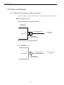
MANDATORY
• Always install a heat exchanger.
Otherwise damage could result.
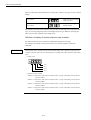
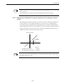
Fig. 2.1 shows an example installation of a heat exchanger.
(Up)
Flow of internal air
Flow of external air
Enclosure
Heat exchanger
(Down)
Fig. 2.1 Example installation of a heat exchanger
2-5
Installing the control panels
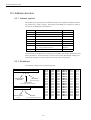
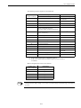
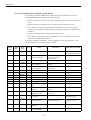
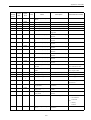
2.1.3 Heat dissipation
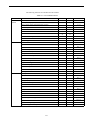
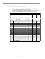
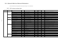
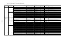
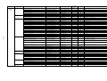
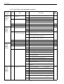
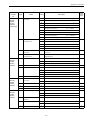
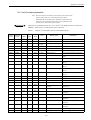
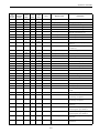
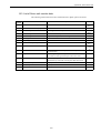
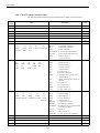
2.1.3 Heat dissipation
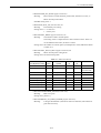
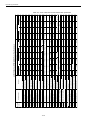
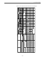
The table below lists the heat each YS 840DI system unit dissipates.
Heat dissipation
Function
CNC unit
Operation panel
Heat dissipation
outside panel
(by heat sink)
(W)
Minimum
air flow rate
(m/s)
−
−
−
190
280
2.5
Heat
Total heat
dissipation
dissipation
inside panel
(W)
(W)
Name
PCU50
130
OP010F □
24
NC keyboard
Machine control panel
OP032S
Power supply module
PS module 10
Power supply backup
module
UPS module
10
Power supply backup
battery
UPS BATTERY
1
Machine control panel
I/O
PP module
11
10.5
I/O power supply module PS307 (24 VDC/2A output)
10
PS307 (24 VDC/5A output)
18
PS307 (24 VDC/10A output)
30
Interface module
ET200M
4.5
Digital input module
SM321 (DI32 × 24 VDC)
6.5
SM321 (DI16 × 24 VDC)
3.5
SM321 (DI16 × 24 VDC source)
3.5
SM321 (DI16 × 120 VAC)
4.1
SM321 (DI8 × 120/230 VAC)
4.9
SM322 (DO32 × 24 VDC/0.5A)
0.26
SM322 (DO16 × 24 VDC/0.5A)
0.19
SM322 (DO8 × 24 VDC/2A)
6.8
Digital output module
9
SM322 (DO16 × 120 VAC/1A)
Digital I/O module
Relay output module
Converter*
SM322 (DO8 × 120/230 VAC/2A)
8.6
SM323 (DI16/DO16 × 24 VDC/0.5A)
6.5
SM323 (DI8/DO8 × 24 VDC/0.5A)
4.5
SM322 (DO16 × 120 VAC REL)
4.5
SM322 (DO8 × 120/23O VAC REL)
2.2
CIMR-MRXN20455A
470
CIMR-MRXN20375A
CIMR-MRXN20305A
CIMR-MRXN20225A
CIMR-MRXN20185A
CIMR-MRXN20155A
CIMR-MRXN20115A
CIMR-MRXN27P55A
CIMR-MRXN25P55A
2-6
2.1 Designing the panels
Heat dissipation
Function
Heat
Total heat
dissipation
dissipation
inside panel
(W)
(W)
Name
Heat dissipation
outside panel
(by heat sink)
(W)
Minimum
air flow rate
(m/s)
Converter *
CIMR-MRXN23P75A
2.5
Inverter *
CIMR-MXN20375A
2.5
687
213
474
270
90
180
180
70
110
SGDK-3030AEA
290
120
170
SGDK-2020AEA
230
100
130
−
−
CIMR-MXN20305A
CIMR-MXN20225A
CIMR-MXN20185A
CIMR-MXN20155A
CIMR-MXN20115A
CIMR-MXN27P55A
CIMR-MXN25P55A
CIMR-MXN23P75A
1-axis servo unit *
SGDK-75AEA
2.5
SGDK-60AEA
SGDK-50AEA
SGDK-30AEA
SGDK-20AEA
SGDK-15AEA
SGDK-10AEA
SGDK-05AEA
2-axis servo unit *
2.5
SGDK-1515AEA
SGDK-1010AEA
SGDK-0505AEA
Reactor
UZBA-B150A 0.07mH
* Heat dissipation of a converter, inverter or servo unit is at a 70% load.
2-7
−
Installing the control panels
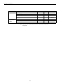
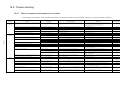
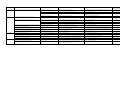
2.1.4 Power consumption
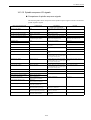
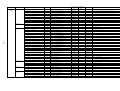
2.1.4 Power consumption
The table below lists the power each YS 840DI system unit consumes. When designing a
control panel, use this data.
Function
Name
Power supply module PS module 10
Power
consumption
(supply voltage)
2.6A 270W
(200 VAC)
Other units powered by this unit
• Power supply backup module
(UPS module 10)
• Power supply backup battery
(UPS BATTERY)
• CNC unit (PCU50)
• Operation panel/NC keyboard
(OP010F □ )
Machine control
panel
OP032S
6W
(24 VDC)
None
Machine control
panel I/O
PP module
11W
(24 VDC)
None
I/O power supply
module
PS307(2A)
10W
(200 VAC)
PS307(5A)
18W
(200 VAC)
PS307(10A)
30W
(200 VAC)
Converter
CIMR-MRXN20455A
(200 VAC)
CIMR-MRXN20375A
(200 VAC)
CIMR-MRXN20305A
(200 VAC)
CIMR-MRXN20225A
(200 VAC)
CIMR-MRXN20185A
(200 VAC)
CIMR-MRXN20155A
(200 VAC)
CIMR-MRXN20115A
(200 VAC)
CIMR-MRXN27P55A
(200 VAC)
CIMR-MRXN25P55A
(200 VAC)
CIMR-MRXN23P75A
(200 VAC)
2-8
• Interface module (ET200M)
• I/O module (SM321/322/323)
• Power supply for I/O loads
• Inverter
• Servo unit
2.2 Protecting against electric noise
2.2 Protecting against electric noise
2.2.1 Separation of cables
There are three types of cables used in the YS 840DI system: AC Power, DC power, and signal. These types of cables must be separated from each other as follows:
Type
AC power (1)
Cable
AC power supply lines
(primary/secondary)
Power cables to spindle and servo
motors
AC lines to solenoids, contactors, and
relays
DC power (2)
24 VDC power supply lines to CNC,
I/O, and power supply modules
24 VDC I/O lines between I/O and
machine
24 VDC lines to solenoids and relays
Signal (3)
PROFIBUS-DP cables between CNC
and I/O module and between I/O
module and converter
RS232C cables
Cables to manual pulse generator
Separation requirements
These cables must not be bundled with DC power
cables (2) or signal cables (3), or must be provided
with an electromagnetic shield.
Solenoids and relays must be provided with a surge
absorber or a diode.
These cables must not be bundled with AC power
cables (1), or must be provided with an electromagnetic shield.
These cables must be separated far enough from
signal cables (3). DC solenoids and DC relays
must be provided with a diode.
These cables must not be bundled with AC power
cables (1), or must be provided with an electromagnetic shield.
These cables must be separated far enough from
DC power cables (2). Cables that need to be
shielded must always be shielded.
Encoder cables between spindle
inverter and spindle motor
Encoder cables between servo unit
and servo motor
Cables to separately mounted PG
Battery cables
Other cables that need to be shielded
INFO
• Two cables are considered to be bundled with each other if they are less than 100 mm apart.
• An electromagnetic shield is a grounded iron plate separating a type of cables from another.
2-9
Installing the control panels
2.2.2 Noise-proof devices
2.2.2 Noise-proof devices
Installing CR-type surge absorbers
Provide AC-powered solenoids, contactors, relays, and induction motors with a CR-type
surge absorber.
For solenoids, contactors, and relays:
AC
Solenoid
電磁弁
Surge
absorber
スパークキラー
Contactor
or relay
コンタクタ,リレー
Surge
absorber
スパークキラー
Note: A surge absorber must be installed as close to a coil as possible.
For induction motors:
R
Surge
absorber
Surge absorber
S
Motor
Surge absorber
T
Note: A surge absorber must be installed as close to a motor as possible.
INFO
Construction of a surge absorber
R
C
The recommended values of C and R are as follows:
• R = DC resistance of a coil (Ω)
2
2
10
20
• C = I to I (μF)
Note: I = Steady-state current of a coil
2-10
2.2 Protecting against electric noise
Installing diodes
Provide DC-powered contactors and relays with a diode.
+
−
Contactor or relay
Coil
Diode
Note: A diode must be installed as close to a coil as possible.
INFO
The recommended voltage and current ratings of a diode are twice the voltage and current ratings of a
coil respectively.
2-11
Installing the control panels
2.2.3 Grounding
2.2.3 Grounding
The grounding wire from each unit must be connected to the enclosure or the grounding
plate directly.
Example grounding wiring
S.V
200 VAC
U
LF
M
V
W
CN
CN
E
PG
E
Enclosure
Operation relay
sequence
LF
AVR
Single-point grounding
(Grouding resistance 100Ωor less)
• Wires for grounding must be in accordance with applicable electrical installation regulations and the internal wiring rules.
• The grounding terminal of a servo motor must be wired to the grounding terminal of the
corresponding SERVOPACK.
• All wires to be grounded must be directly connected to a single point whose grounding
resistance 100Ωor less. Otherwise electric shock, a fire, or malfunction could result.
• The single grounding point for this product must not be used to also ground a power
device. Otherwise malfunction could result.
2-12
2.2 Protecting against electric noise
2.2.4 Cable shield clamp
A cable between a servo unit and a motor encoder must be shielded and grounded. To
securely connect the shield of the cable to a grounding plate, use a cable clamp as illustrated
below.
Cable clamping is not only for mechanically supporting a cable but also for securely grounding its shield, and thus essential to the safe operation of the system. The recommended cable
clamping method is that stripping off a length of the insulation of a cable to expose its
shielding braid, placing a cable clamp over the shielding braid, and fixing the cable clamp to
a grounding plate, as illustrated below.
Cable
Type 1
DF8401485
Type 2
DF8404817
19.5
19.5
Cable clamp
Minimum
Minimum
19.5
19.5
30
Cable clamp
6.5
Grounding plate
Cable
Fig. 2.2 Cable clamp
A grounding plate must be installed near a SERVOPACK as illustrated below.
SERVOPACK
Connector
Cable
Grounding plate
Cable clamp
Shielding braid
Fig. 2.3 Grounding plate position
2-13
30
Shielding braid
8
Installing the control panels
2.3.1 Installing the CNC units
2.3 Installation precautions
When designing an enclosure to contain a CNC or other unit, observe the precautions below.
2.3.1 Installing the CNC units
When installing the CNC unit in an enclosure, observe the following precautions:
Air flow
(Up)
Operation panel(OP10F
)
100100mm以上
mm or more
• Install the CNC unit such that it is oriented as shown below.
FAN
CNC unit (PCU50)
CNC
CNC unit
ユニット
(PCU50)
(Down)
Space for wiring and maintenance
Rear view (inside the panel)
160160mm以上
mm or more
(PCU50)
Side
view
側面
Fig. 2.4 CNC unit installation
• The CNC unit has a cooling fan at the top on the rear side. Do not place any obstacle
that could block the air flow. Otherwise damage could result.
• Provide a 100 mm or more space over and a 160 mm or more space under the CNC unit
for air circulation as well as for wiring and maintenance work.
INFO
The CNC unit is normally provided with an NC keyboard under it. Thus a 160 mm or more space will
be naturally provided under the CNC unit.
2-14
2.3 Installation precautions
2.3.2 Installing the feed/spindle SERVOPACK
When installing the feed or spindle SERVOPACK in an enclosure, observe the following
precautions:
• Since the SERVOPACK is a wall-mounted type, it must be secured vertically to a wall of
an enclosure with screws or bolts.
• The SERVOPACK must be installed such that checking, replacement or other maintenance work is easy.
• The SERVOPACK must be installed such that its heat sink fins are exposed to the outside cooling air to reduce the internal temperature rise. This way the panel can be airtight and the size of the heat sink can be designed smaller (see the figure below).
• The flow rate of the cooling air flowing through the heat sink fins must be at least 2.5 m/
s as measured near the fins.
• The outside cooling air must be applied to each heat sink at the specified flow rate.
• The fan producing the cooling air should preferably be made of metal. A plastic fan
could be deteriorated by machining oil, causing the drive to be damaged.
Heat sink
Outside air
Feed/spindle
SERVOPACK
Fig. 2.5 Heat sink as exposed to the outside
2-15
Installing the control panels
2.3.3 Orientation of and installation space for the SERVOPACK
2.3.3 Orientation of and installation space for the SERVOPACK
The SERVOPACK must be installed vertically and sufficient space must be provided around
them for better cooling efficiency, as shown below.
Air flow
Converter Inverter
120 mm
or more
Servo unit
70 mm
max.
Air duct within an
outermost enclosure
Air flow
FAN
Heat
sink
Sealing at screw
120 mm or more
5 mm or more
Air flow
Left and right space
Upper and lower space
Fig. 2.6 SERVOPACK’s orientation and space
• All SERVOPACKs are designed so as to have their heat sink exposed to the outside.
• For the outside dimensions of and installation space for the SERVOPACKs, see the relevant outline drawings given in the General Documentation - Hardware.
• The allowable temperature range of the air draft against the SERVOPACK is 0-45 ℃ at
the heat sink (outside) and 0-55 ℃ inside.
• Apply sealing agent to the mounting screw areas of the SERVOPACK to prevent oil
from entering inside.
• The SERVOPACK has a built-in fan as shown in Fig. 2.6.
• To prevent the SERVOPACK from overheating, arrange other units and devices such
that the required space is provided over and under the SERVOPACK.
• If an air stirring fan is installed in a panel, the fan must be oriented such that the air does
not directly hit the SERVOPACK (to prevent the SERVOPACK from collecting more
dust).
A space must be provided to the right and left of each SERVOPACK as follows:
SERVOPACK width
Space width
74 mm
0.5 mm (right and left)
148 or 248 mm
1.0 mm (right and left)
2-16
2.3 Installation precautions
If two SERVOPACKs are installed side by side, the minimum space between them is a total
of the right-side space required of the left SERVOPACK and the left-side space required of
the right SERVOPACK, as illustrated below.
The space required
of SERVOPACK A
SERVOPACK
A
1.0
The space required
of SERVOPACK D
1.0
0.5
SERVO
PACK
C
SERVOPACK
B
148 or 248
0.5
1.5
SERVOPACK
D
74
2.3.4 Installation space for the I/O modules
The I/O modules must be installed as illustrated below.
Machine control panel I/O (PP72/48)
(Up)
100mm
5mm
5mm
120mm
40mm
(Down)
INFO
(Left)
(Right)
There must be a 120 mm or more space to the left of the machine control panel I/O to provide for
PROFIBUS-DP and power supply connections.
2-17
Installing the control panels
2.3.5 Installing lightning-surge absorbers
I/O modules
(Up)
180 mm or more
DIN rail
40mm
20mm
I/O
module
PS module
40mm
(Left)
20mm
(Right)
(Down)
INFO
The enclosure that houses the I/O module must be at least 180 mm deep so that the front cover can be
opened safely.
2.3.5 Installing lightning-surge absorbers
Lightning-surge absorbers must be installed to prevent electric and electronic devices from
malfunctioning even if the power, communication, or signal line is subjected to a highenergy disturbance such as switching or lightning surge. Normally the power line should be
provided with surge absorbers as shown below.
• Normal-type surge absorber between phases
• Common-type surge absorber between phases and ground
200/220/230 VAC
50/60Hz
Control panel
Circuit breaker
Electronic devices
Circuit
protector
CNC
Surge absorber
between phases
and ground
Conver
ter
Inverter
SERVO
PACK
Surge absorber
between phases
Panel grounding plate
Grounding resistance
100Ωor less
Motor
Fig. 2.7 Installing lightning-surge absorbers
2-18
2.3 Installation precautions
Recommended surge absorbers
Application
IMPORTANT
Designation
Make
Normal-type surge absorber
between phases
RAV-781BYZ-2
Okatani Electric
Common-type surge absorber
between phases and ground
RAV-781BXZ-4
Okatani Electric
If the surge absorber failed and got shorted due to repeated lightning or switching surge, the wiring and
devices could burn. To prevent this, 5-A fuses or other circuit protectors must be provided in the protected line.
2-19
Installing the control panels
2.3.5 Installing lightning-surge absorbers
2-20
Chapter 3
Installing the motors
This chapter presents the precautions to be observed when installing the YS
840DI motors.
3.1 Servo motors - - - - - - - - - - - - - - - - - - - - - - - - - - - - - - - - - - - 3-2
3.2 Spindle motors- - - - - - - - - - - - - - - - - - - - - - - - - - - - - - - - - - 3-3
3-1
Installing the motors
3.1 Servo motors
The SGMKS-type servo motors must be used indoor. The environmental requirements for the
motors are these:
• Indoor and free of corrosive or flammable gas
• Well ventilated and free of excessive dust, dirt, or moisture
• Ambient temperature: 0-40 ℃
• Relative humidity: 20-80%RH with no dew
• Can be easily cleaned and checked
3-2
3.2 Spindle motors
3.2 Spindle motors
• The spindle motor must be provided with enough space so that it is cooled effectively by
its cooling fan. Especially, there must be a 100 mm or more space between the no-load
side of the spindle motor and a nearest machine part. If the spindle motor were not
cooled enough, a motor overheat protector could operate even if the spindle motor runs
at the rated load.
• The bed, foundation or mount on which the spindle motor is installed must be rigid
enough. Otherwise the bed could vibrate due to the weight of the motor and the
dynamic load from the machine.
• The installation site must be free of excessive dust or iron particles. As the air forced by
the built-in cooling fan passes along the motor core, it could be blocked by any accumulated dust in the way. If the spindle motor were not cooled enough, a motor overheat
protector could operate even if the spindle motor runs at the rated load.
3-3
Installing the motors
3-4
Chapter 4
Connection method
This chapter describes how to wire units and devices together.
4.1 Arrangement of connectors and switches - - - - - - - - - - - - - - - 4-2
4.1.1 CNC unit - - - - - - - - - - - - - - - - - - - - - - - - - - - - - - - - - - - - - - - - - - - - 4-2
4.1.2 Power supply module - - - - - - - - - - - - - - - - - - - - - - - - - - - - - - - - - - - 4-6
4.1.3 I/O module - - - - - - - - - - - - - - - - - - - - - - - - - - - - - - - - - - - - - - - - - - - 4-6
4.1.4 Converter- - - - - - - - - - - - - - - - - - - - - - - - - - - - - - - - - - - - - - - - - - - - 4-9
4.1.5 Inverter - - - - - - - - - - - - - - - - - - - - - - - - - - - - - - - - - - - - - - - - - - - - 4-10
4.1.6 Servo unit - - - - - - - - - - - - - - - - - - - - - - - - - - - - - - - - - - - - - - - - - - 4-11
4.2 Power on/off signals - - - - - - - - - - - - - - - - - - - - - - - - - - - - - 4-14
4.2.1 Wiring for servo power-on and other signals - - - - - - - - - - - - - - - - - - 4-14
4.2.2 UPS module timer setting - - - - - - - - - - - - - - - - - - - - - - - - - - - - - - - 4-17
4.2.3 Time chart - - - - - - - - - - - - - - - - - - - - - - - - - - - - - - - - - - - - - - - - - - 4-18
4.3 Wiring units and devices - - - - - - - - - - - - - - - - - - - - - - - - - - 4-19
4.3.1 PROFIBUS-DP address and termination setting - - - - - - - - - - - - - - - 4-19
4.3.2 Setting the rotary switches on the inverters and servo units - - - - - - - 4-21
4-1
Connection method
4.1.1 CNC unit
4.1 Arrangement of connectors and switches
4.1.1 CNC unit
Definitions of the surfaces of combined CNC unit (PCU50) and
operation panel (OP010F □ )
The YS 840DI system uses a combination of the CNC unit (PCU50) and the operation panel
(OP010F □ ). The surfaces of the combined units are defined as follows:
Top surface
Top surface
Operation panel
(OP010F□)
CNC unit
(PCU50)
Rear
surface
Left side
surface
CNC unit
(PCU50)
Bottom
surface
Bottom
surface
(Left side view)
(Rear view)
4-2
Right side
surface
4.1 Arrangement of connectors and switches
Arrangement of connectors
The arrangement of connectors on each surface is as shown below.
UPS module
24 VDC input
Battery module
(PROFIBUS-DP)
X101
(MPI)
X111
PS/2 mouse
PS/2 Mouse
COM1
X1
LPT1
COM2
VGA
MPV/L2-DP
Ethernet
USB
PS/2 Keyborad
X121
(Handle PG)
Emergency stop
UPS I/F
PC card drive
Bottom surface
Connector for an external 3.5-inch floppy-disk drive
RESET
Reset button
Cooling fan
Top surface
IMPORTANT
Pressing the reset button causes the system to reboot. Do not touch the reset button unless this is what
you exactly want.
4-3
Connection method
4.1.1 CNC unit
Connector for an external 3.5-inch
floppy-disk drive
Mounting rail
Grounding terminal
Right side surface
INFO
Remove the mounting rail if you want to combine the CNC unit with the OP010F □ operation panel.
4-4
4.1 Arrangement of connectors and switches
Connector for an external 3.5-inch floppy-disk drive
Fixing latch
Hard disk drive unit
Fixing screw
Bottom surface with connectors
Rear surface
INFO
The left side surface is not shown because there is no connector on it.
4-5
Connection method
4.1.2 Power supply module
4.1.2 Power supply module
Power supply backup module (UPS module 10)
o.k
Bat
Alarm
tmax
DC-USV-Modul 10
6EP1931-2EC01
On / Off
n.c.
UBat
Alarm
1 2 3 4 5
o.k
タイマ設定
t
+160s
+80s
+40s
+20s
+10s
5s
Bat
Timer setting
UL+
X2.1 2.2 2.3 2.4 2.5 2.6 2.7 2.8 2.9
15A
2424V電源入力
V power supply input
In
2424V電源出力
V power supply output
Out
Battery module
バッテリモジュール
Signals
for power
電源切入シーケンス
supply on/off sequence
L+
X1.1
M
X1.2
L+
X1.3
M
X1.4
+Bat
X1.5
-Bat
X1.6
用信号
4.1.3 I/O module
Machine control panel I/O (PP72/48)
PROFIBUS-DP address
setting switch
OVERTEMP RESET
PROFIBUS-DP
connector
X2
24 VDC input
connector
X1
EXCHANGE
READY
POWER
S1
X333
X222
I/O connector 3
4-6
I/O connector 2
X111
I/O connector 1
4.1 Arrangement of connectors and switches
PS module for I/O (PS307(2A))
LED indicating that the 24
VDC output is available
24VDC
Voltage selector
230V
24 VDC ON/OFF
switch
I
L1
System voltage and
grounding terminal
N
L+
M
L+
M
24 VDC output terminal
Cable clamp
Remote I/O interface module (ET200M)
With the panel closed
SF
BF
With the panel open
SIEMENS
ON
PROFIBUS-DP
SF
BF
PROFIBUS-DP
interface
(9-pin socket)
ON
Panel
SIMATIC
ET 200M
Cable pit
ON
64
32
16
8
4
2
1
IM 153-1
Slot
Status/error indicator
DP address setting
Jumper (removable)
Version
2
X2
3 4
Catalog number
M
L
M
+
DC24V
153-1AA02-OXB0
4-7
Power supply and
grounding connector
Connection method
4.1.3 I/O module
Digital I/O module (SM321 (D132 × 24 VDC))
Byte 0
Byte 1
0
0
1
1
2
2
3
3
4
4
5
5
6
6
7
7
0
0
1
1
2
2
3
3
4
4
5
5
6
6
7
7
Byte 2
Byte 3
Channel number
Status LED (green)
Dummy module (DM370)
NA
A
Address switch
X 2
3 4
Rear view
Front view
4-8
4.1 Arrangement of connectors and switches
4.1.4 Converter
Converter (CIMR-MRXN20455A(45kW))
P/+
DC power terminal block (8P) M6
N/-
CN7A (Control power connector)
CN7B (Control power connector)
CN5A (I/O bus connector)
CN5B (I/O bus connector)
CHARGE
Indicator (red)
CN8 (Battery input)
CN1 (I/O connector)
CN9 (PROFIBUS)
CN6 (Analog monitor connector)
SW1 (PROFIBUS address)
CN3 (PG input connector)
R/L1
S/L2
T/L1
E
A2/t (Control power input) M4
A1/t (Control power input) M4
Grounding terminal M6
Main power input ( 3P) M10
4-9
Connection method
4.1.5 Inverter
4.1.5 Inverter
Inverter (CIMR-MXN20305A(30kW))
P/+
N/-
DC power terminal block (4P) M6
CN7A (Control power connector)
CN7B (Control power connector)
CN5A (I/O bus connector)
CN5B (I/O bus connector)
CHARGE
Indicator (red)
SW1 (Rotary switch)
RDY (Indicator (green))
CN4 (Pulse PG input)
CN1 (I/O connector)
CN6 (Analog monitor connector)
CN2 (Serial PG input connector)
U/T1 V/T2 W/T3 E
Motor frame ground terminal : M6
Motor output terminal block (3P) M8
E (Grounding terminal) M6
4-10
4.1 Arrangement of connectors and switches
4.1.6 Servo unit
1-axis servo unit (SGDK-60AEA (6 kW), SGDK-75AEA (7.5 kW))
DC power terminal block(4P)
M6 screw
Control power connector
(CN7)
I/O bus connector
(CN5)
Rotary switch
(SW1)
Indicator
CHARGE : red
Indicator
RDY : green
Connector for external PG
(CN4)
I/O connector
(CN1)
Analog monitor connector
(CN6)
PG input connector
(CN2)
Motor frame ground terminal
M6 screw
Motor output terminal block 3
( P)
M6 screw
Grounding terminal
M6 screw
4-11
Connection method
4.1.6 Servo unit
1-axis servo unit (SGDK-50AEA (5 kW))
DC power terminal block (2P)
P
+
Control power
connector
M6 screw
N
-
(CN8)
I/O bus connector
(CN5)
Rotary switch
(SW1)
Indicator
CHARGE : red
Connector for external PG
(CN4)
Indicator
RDY : green
I/O connector
(CN1)
Analog monitor connector
(CN6)
Motor output connector
(CN8)
PG input connector
(CN2)
Grounding terminal
M4 screw
4-12
4.1 Arrangement of connectors and switches
2-axis servo unit (SGDK-0505AEA (0.5 kW), SGDK-1010AEA (1 kW),
SGDK-1515AEA (1.5 kW), SGDK-2020AEA (2 kW), SGDK-3030AEA
(3 kW))
DC power terminal block(2P)
P
+
N
-
M6 screw
Control power connector
(CN7)
I/O bus connector
(CN5)
Rotary switch
(SW1)
Indicator
CHARGE : red
Connector for external PG
(CN14)
Indicator
RDY,RDY2 : green
Motor output connector
(CN18)
I/O connector
(CN1)
Analog monitor connector
(CN16,CN26)
Motor output connector
(CN28)
PG input connector
(CN12,CN22)
Connector for external PG
(CN24)
Grounding terminal
M4 screw
4-13
Connection method
4.2.1 Wiring for servo power-on and other signals
4.2 Power on/off signals
4.2.1 Wiring for servo power-on and other signals
The wiring for the servo power-on and brake release output signals must be done as follows:
Wiring between units
Servo power-on output signal (SVMX)
Converter unit
CIMR-MRXN
UL20276AWG28×10
CN1
10220-52A2JL
Servo power-on
circuit
10120-3000VE
(10320-52A0-008)
Brake release output signal (BKX)
Servo unit
SGDK-□□/SGDK-□□□□
UL20276AWG28×10
CN1
10226-52A2JL
10126-3000VE
(10326-52A0-008)
4-14
Motor brake control
circuit
4.2 Power on/off signals
Detailed wiring drawing
200 VAC50/60Hz
R S T E
Circuit breaker or other circuit protector
Z1 To the
Z2 spindle
Z3 motor fan
Main circuit
breaker
SV
M
Converter
U
S/L2
Y Reactor V
R/L1
X
Z
T/L3
W
E
A1
Power supply
A2
L
N
E
MCON
+24V
+V
0V
-V
/MCON
SVMX
Emergency stop switch
SVM
ESP
/ESP
-8
5
ESPX
CN1
-14
Brake
power
supply 1
1
2
3
6
BKX1
-15
-16
5
3
6
BKX
2
ON
ESP
X
To servo
motor brake
UPS module
In
*2
Out
CNC unit
X1
L+
M
L+
M
+Bat
-Bat
+
+24V
−
0V
PE
E
X121
NC ready sequence
SET
= DB10.DBX7.3
A DB10.DBX104.7
= DB10.DBX6.3
PBX
Battery module
*4
*3
+24V
0V
+24V
0V
Shutdown sequence
A DB10.DBX60.3
= DB10.DBX57.3
Emergency stop sequence
AN DB10.DBX60.2
DB10.DBX56.1
=
AN DB10.DBX56.1
DB10.DBX56.2
=
SVM
X
+
L1
N
P
E
JUMPER
L+
M
M
NCRX
PB
X
Bat
PS module
120VAC
ONLY
NCMX
NCM
X
4
24 VDC -20,21
input
-1
-5
-24
-6
-25
-22
-2
+24V
0V
UPS Bat.On
0V
EMG.In
0V
Emergency stop
switch
NC Rdy.Out(+24V)
NCRX
0V
Fig. 4.1 Wiring for the SVMX and BKX output signals
4-15
Fuse
2
OFF
ON
o.k
Alar
m
On/
Off
Brake
power
supply 2
-17
BKX2
To servo
motor brake
1
Servo unit
*1
4
ESP
X
*5
-18
CN1A
-7
CR
PB
X
NCM
X
CN1A
-17
*1
Connection method
4.2.1 Wiring for servo power-on and other signals
IMPORTANT
*1. The brake release output signal as shown in Fig. 4.1 is for 2-axis servo units. For 1-axis servo
units, use only pins 14 and 15. For 2-axis servo units, use pins 14 and 15 for the first axis, and
pins 16 and 17 for the second axis.
Servo unit
Axis
1-axis servo unit
−
Connector pins
CN1 − 14 ( + 24V)
CN1 − 15 (0V)
2-axis servo unit
First axis
CN1 − 14 ( + 24V)
CN1 − 15 (0V)
Second
axis
CN1 − 16 ( + 24V)
CN1 − 17 ( + 0V)
*2. If the voltage of power input to the PS module is 100-120 VAC, short the JUMPER120 VAC
ONLY terminals together.
*3. To use the UPS module, short the On/Off terminals together. Otherwise an alarm would result.
*4. To use the battery module, insert a 15-A fuse in its fuse holder. Otherwise an alarm would result.
When inserting a fuse, a spark may occur (if the battery is in the charged state). Don’t worry
about the spark since it’s quite safe to you and the module.
*5. To make the UPS, emergency, and NC-ready functions available, program the necessary
sequences in the PLC. Once the shutdown sequence has been programmed, disconnecting or otherwise disabling the UPS module would cause a switched-on NC to shutdown soon. To make the
NC powered up normally, always keep the UPS module functional.
4-16
4.2 Power on/off signals
• The brake release output signal to control the brake of a motor must come from the servo unit driving that motor.
INFO
• The UPS module must not be used to power other than those units shown in Fig. 4.1.
• Wire between the Alarm terminals and an I/O module as necessary.
• Interlock the BKX relay as necessary by externally adding an interlock signal to the brake release
output signal.
• It is the responsibility for the customer to provide the emergency stop switch and its wiring.
• It is the responsibility for the customer to provide the X121 connector (37-pin D-Sub female connector) and related wiring.
• The SVMX, ESPX, and BKX relays must be 24 VDC miniature relays (preferably LY-2 from
OMRON).
4.2.2 UPS module timer setting
The UPS module must have its timer set so that the 24 VDC power supply will be available
for a certain period even after a blackout occurs (to earn time necessary for memory data to
be transferred to a hard disk). The relationship between timer setting and covered period is
shown below. The covered period should be at least 85 seconds.
Covered period
5
15
25
35
45
55
65
75
85
95
105
115
125
135
145
155
165
175
185
195
205
215
225
235
245
255
265
275
285
295
305
1
1
1
1
1
1
1
1
1
1
1
1
1
1
1
1
1
1
1
1
1
1
1
1
1
1
1
1
1
1
1
1
0
0
0
0
0
0
0
0
0
0
0
0
0
0
0
0
0
1
1
1
1
1
1
1
1
1
1
1
1
1
1
1
1
x
0
0
0
0
0
0
0
0
1
1
1
1
1
1
1
1
0
0
0
0
0
0
0
0
1
1
1
1
1
1
1
1
x
4
0
0
0
0
1
1
1
1
0
0
0
0
1
1
1
1
0
0
0
0
1
1
1
1
0
0
0
0
1
1
1
1
x
5
0
0
1
1
0
0
1
1
0
0
1
1
0
0
1
1
0
0
1
1
0
0
1
1
0
0
1
1
0
0
1
1
x
6
0
1
0
0
1
0
1
0
1
0
1
0
1
0
1
0
1
0
1
0
1
0
1
0
1
0
1
0
1
0
1
0
x
X 400
On
315 max
2
3
Fig. 4.2 UPS module timer setting
Position of the timer switch elements
1 means ON, 0 means OFF, and x means any position (irrelevant).
If switch element 1 is set to the OFF position, the UPS module supplies power as long as the
supplied voltage is above the low battery level.
4-17
4-18
Brake power supply 1
Brake power supply 2
BKX1
BKX2
SVM
(servo power ON)
PBX (self-held ON)
SVMX (servo ready)
Alarm reset
(manually from machine
control panel)
ESPX
(forced braking ON)
Emergency stop SW
(manual, NC-contact)
Pulse enable (PLC)
Controller enable (PLC)
NCRX (NC ready)
NC start
PLC start
UPS module
(24 VDC output)
UPS BAT ON
(NC contact, UPS
start signal)
PS module
(24 VDC output)
NCMX
OFF SW
(manual, NC contact)
ON SW
(manual, NO contact)
Converter's
control power
Main circuit breaker
PLC start
Emergency stop reset
Wait for NC ready sequence start
Wait for PLC start
First stage : NC power on
Brake released
Second stage : servo power on
Brake activated
Combined MD36060 and MD3426 settings effective
Emergency stop activated (manually or by an alarm)
PLC stop
Automatic shutdown
sequence
PLC stop
UPS timer setting (in seconds)
Power-off input
Connection method
4.2.3 Time chart
4.2.3 Time chart
The time chart below illustrates the typical timings of power-related signals.
4.3 Wiring units and devices
4.3 Wiring units and devices
4.3.1 PROFIBUS-DP address and termination setting
Shown below are examples of PROFIBUS-DP address setting and termination setting.
Example wiring
CNC unit
PCU50
Address 2
X101
Termination ON
Machine control panel
I/O
X2
Termination
OFF
Machine control panel
I/O
S1
X2
8
S1
9
Termination OFF
I/O module
IM module
DP address
switch 3
Termination OFF
I/O module
IM module
Converter
DP address
switch 4
Termination
OFF
CN9
Rotary switch
○
6
○
7
Converter
Termination
ON
CN9
Rotary switch
4-19
Connection method
4.3.1 PROFIBUS-DP address and termination setting
CNC unit address setting
The address of the CNC unit is fixed to 2 (no hardware setting).
Machine control panel I/O
Set the DIP switch S1 on the PC board to a value between 3 and 32 such that each unit has a
unique value.
I/O module
Set the DP address switch (DIP switch) on the ET200M interface module to a value between
3 and 32 such that each unit has a unique value.
Converter
Set the DIP switch to a value between 3 and 32 such that each unit has a unique value.
Termination setting
Set the termination switch on each PROFIBUS-DP connector as given below.
Unit
INFO
Setting
CNC unit
ON
Units in between
OFF
End units
ON
• Any unit other than CNC must not have its address set to 0, 1, or 2.
• Up to 32 PROFIBUS-DP addresses are available with the YS 840DI system.
• For information on how to specify addresses in software, see Chapter 9, Hardware Configuration.
4-20
4.3 Wiring units and devices
4.3.2 Setting the rotary switches on the inverters and servo units
Each of the inverters and servo units has a rotary switch to specify a PROFIBUS-DP slot
allocated to it. Set the rotary switch as follows:
• Each axis must have its rotary switch set to a unique number in sequence starting with 0.
• 2-axis servo units have only one rotary switch but use two values because each axis
needs a unique value. Thus, if a 2-axis servo unit has its rotary switch set to 2, the values 2 and 3 are actually used by those two axes, and the next unit must have its rotary
switch set to 4. A 2-axis servo unit should have its rotary switch set to an even number
(0, 2, 4, ...).
• The units connected to one converter may have their rotary switch set to a unique number between 0 and 6. The sequence in position of the units need not correspond to the
sequence of the set values of their rotary switches.
INFO
If a unit has its rotary switch wrongly set, the corresponding LED above the PROFIBUS connector on
the converter would go red (normally green).
4-21
Connection method
4.3.2 Setting the rotary switches on the inverters and servo units
4-22
Chapter 5
Assembling and replacing
5.1 Installing the CNC unit - - - - - - - - - - - - - - - - - - - - - - - - - - - - 5-2
5.2 Replacing the servo unit fan - - - - - - - - - - - - - - - - - - - - - - - - 5-8
5.2.1 Procedure for replacing the 0.5-3.0 and 5.0 kW servo unit fans - - - - - 5-8
5.2.2 Procedure for replacing the 6.0 and 7.5 kW servo unit fans - - - - - - - - 5-9
5.3 Installing the servo unit optional board - - - - - - - - - - - - - - - 5-10
5.3.1 Procedure for installing the board for the 0.5-3.0 and 5.0 kW
servo units - - - - - - - - - - - - - - - - - - - - - - - - - - - - - - - - - - - - - - - - - 5-10
5.3.2 Procedure for installing the board for the 6.0 and 7.5 kW
servo units - - - - - - - - - - - - - - - - - - - - - - - - - - - - - - - - - - - - - - - - - 5-11
5-1
Assembling and replacing
5.1 Installing the CNC unit
This subsection describes how to install the CNC unit (PCU50).
Installation procedure
The CNC unit of the YS 840DI system is normally delivered with the operation panel
attached to it. Make any necessary adjustment to the CNC unit or the operation panel separately, and then assemble them together using the following procedures:
1. Remove the screws in a vinyl bag and a cable fixing seal from the back of the operation
panel.
5-2
5.1 Installing the CNC unit
2. Remove the mounting rail from the CNC unit by unscrewing 4 M4 screws and 4 M3
screws. A Torx wrench or Torx screwdriver is required for this work.
3. Connect 2 flat cables from the operation panel to the CNC unit.
Ensure that the connectors are firmly inserted with their latches fully closed.
5-3
Assembling and replacing
4. Connect the CNC unit and the operation panel together using the supplied screws.
There are four M4 screws and four M3 screws. Use a Phillips screwdriver.
5. Turn the hard disk operation switch on the back of the CNC unit to the operating position until it clicks.
6. Unscrew two M3 screws from the top cover of the CNC unit, and then remove the top
cover. A Torx wrench or Torx screwdriver is required for this work.
5-4
5.1 Installing the CNC unit
7. Unscrew one M3 screw from the slot cover, and then remove the slot cover.
8. Open the MCI Extension Board selector lever (S1).
Selector
lever S1
Release this part
Closed
Open
5-5
Assembling and replacing
9. Insert the MCI Extension Board into the optional board slot as far as it will go.
10.Connect the MCI Extension Board connector to the corresponding connector on the
board above it using the supplied cable.
Ensure that the connectors are firmly inserted with their latches fully closed.
5-6
5.1 Installing the CNC unit
11.Fix the MCI Extension Board in position with the slot cover screw.
12.Reinstall the top cover and secure it with the screws.
A Torx wrench or a Torx screwdriver is required for this operation.
This step concludes the installation procedure.
5-7
Assembling and replacing
5.2.1 Procedure for replacing the 0.5-3.0 and 5.0 kW servo unit fans
5.2 Replacing the servo unit fan
5.2.1 Procedure for replacing the 0.5-3.0 and 5.0 kW servo unit fans
Replace the servo unit fans as follows:
1. Open the PN cover.
2. Unscrew the screw that holds the fan unit. The screw will remain loosely attached to the
panel cover.
3. Remove the fan unit.
4. Disengage the connector.
5. Remove the fan from its fan cover, and install a new one.
Fan unit
ファンユニット
コネクタ
4 Connector
5
Pay
attention to the orientation of
ファンの向きに注意
the
fan (air flow direction)
(吐き出し方向)
3
PN cover
PNカバー
1
Cut-out for routing
ファンリード引出し口
the fan lead
Fan
cover
ファンカバー
2
パネルカバー
Panel
cover
5-8
5.2 Replacing the servo unit fan
5.2.2 Procedure for replacing the 6.0 and 7.5 kW servo unit fans
Replace the servo unit fans as follows:
1. Unscrew the screw that holds the fan cover. The screw will remain loosely attached to
the fan cover.
2. Remove the fan.
3. Disengage the fan connector.
4. Replace the fan with a new one.
Pay attention to the orientation of
the fan (air flow direction)
1
Fan cover
2
See detailed
drawing A
Fan
3
5-9
Assembling and replacing
5.3.1 Procedure for installing the board for the 0.5-3.0 and 5.0 kW servo units
5.3 Installing the servo unit optional board
5.3.1 Procedure for installing the board for the 0.5-3.0 and 5.0 kW servo
units
Install the optional board as follows:
1. Unscrew the screws that hold the optional board cover, and remove the cover.
2. Cut the blind plates off.
3. Install the NPs.
4. Install the optional board and secure it with the screws.
5. Reinstall the optional board cover, and secure it with the screws.
Optional
board
オプション基板
1
4
3
2
5-10
Optional
board
オプションカバー
cover
5.3 Installing the servo unit optional board
5.3.2 Procedure for installing the board for the 6.0 and 7.5 kW servo units
Install the optional board as follows:
1. Unscrew the screws that hold the optional board cover, and remove the cover.
2. Remove the blind plate NP.
3. Install the NPs on the optional board cover.
4. Install the optional board and secure it with the four screws.
5. Reinstall the optional board cover, and secure it with the screws.
4
X4
3
Optional board
オプションカバー
cover
2
Optional
board
オプション基板
1
5-11
Part 2
Software
Chapter 6
Software configuration
6.1 System software components- - - - - - - - - - - - - - - - - - - - - - - 6-2
6.2 Data types - - - - - - - - - - - - - - - - - - - - - - - - - - - - - - - - - - - - 6-3
6.3 Service screen directories - - - - - - - - - - - - - - - - - - - - - - - - - 6-4
6-1
Software configuration
6.1 System software components
The system software components are listed below.
Table 6.1 System software components
Hardware
HMI
Software component
Version
Windows NT
4.0
SP6 (Service Pack)
YS 840DI Start up
V01.00.08
MMC 103
06.00.28
ShopMill
Version 05.03.07
PLC Version 05.02.03
STEP 7
Version 5.0
SP2 (Service Pack)
NC
NC
YORK 9.0
PLC
PLC
4.20.21
Servo unit
F151
Inverter
F026
Converter
00
System number
Example: 00.02.00*
Example: 00*
∗ Example: A system number, as shown in the table above as an example,
changes as the software is revised.
6-2
6.2 Data types
6.2 Data types
The YS 840DI system handles the following data types:
Table 6.2 Data types and locations
Archive type
MMC data
(Part of the HMI)
NC data
Data type
Location
Remarks
Display-Machine-data
Stored in the resident directory.
Machine Data (display parameters)
for operation panel
MBDDE-alarm-text
Stored in the resident directory.
Alarm message tables for different
languages
Tool Managements
User’s custom settings
(for configuration)
Default settings and other data for
tool management
Definitions
yet to be loaded to NC.
System definition program
Standard Cycle
Mostly standard G-code definition
cycles
USER Cycle
Special cycles for user customization
Part-Program
System program
Sub-Program
Mostly machining subprograms with
the SPF extension
Work pieces
User data for machining main programs
Option data
Stored in the resident directory.
Machine data (optional parameters)
Machine data
Machine data
(general, series, axis, and collective)
Setting data
Setting data
Tool offset
User’s custom settings
Machine-specific setting data
(defaults = 0)
Zero offset
User’s custom settings
Machine-specific setting data
(defaults = 0)
Global user data
GUD5, 6, 7
(controlling the cycle files)
Local user data
Definitions
PLC data
Loaded to NC already
SMAC and CST definition programs
Standard Cycle
Mostly standard G-code definition
cycles
USER Cycle
Special cycles for user customization
Part-Program
System programs
Sub-Program
Machining subprograms
Work pieces
Machining main program
PLC data
Archive created in STEP7
Sequence data
6-3
Software configuration
6.3 Service screen directories
This subsection describes the service screen directories.
Use the data selection function to select folder contents to be displayed. Normally, folders
not used are not displayed.
The following directories are in the folder dh of the F drive, YS 840DI, as displayed by the
NT’s Explorer:
Table 6.3 Directories
Data name
Data
type
Description
FDD data
DIR
Not used (free space).
MBDDE alarm list
DIR
Storing alarm text and various language files.
MSD data
DIR
Not used (free space).
NC active data
DIR
Storing the data which cannot be stored in a file format in
the NC memory, such as machine data, origin offsets, corrections, and tool data.
Saved NC data
DIR
This folder is not displayed.
OEM data
DIR
Storing various files.
TMP.DIR
DIR
Temporary directory
WORK
(WORK PIECES)
DIR
Tool management
Backup Directory names
selection in the folder dh
by the
of the F drive,
MMC
YS 840DI, as
extension displayed by the
NT’s Explorer
MB
.mb,Cus.dir,
_nc _act.dir
OEM
.oem.dir
Storing various machining programs
(machine-specific data files).
WKS
.wks.dir
DIR
Storing configuration and tool list data.
WZV
.wzv.dir
Diagnosis
DIR
Subdirectories are used. Data can be stored in diagnosis
screens.
Interactive programming
DIR
Subdirectories are used. Interactive system data can be
stored.
Definition
DIR
Storing global user data and SMAC system definition files.
Standard cycles
DIR
Storing G-code cycles and program control cycles.
Continuous machining
DIR
Not used (free space).
Clip board
CLP
Not used (free space).
clip.clp
Archive
DIR
Storing NC and PLC archives.
arc.dir
Comment
DIR
Storing comments and messages.
.pda.dir
Subprogram
DIR
Storing machining subprograms.
System
DIR
Not used (free space).
Start-up
DIR
Not used (free space).
Template
DIR
Storing circularity and other test waveforms and image files.
Data management
DIR
Storing data that is to be managed by the user.
Part programs
DIR
Storing data that is to be managed by the user.
MPF
.mpf.dir
Machine data display
DIR
Storing display-related machine data.
BD
Bd..dir
.dg.dir
.def.dir
SPF
.spf.dir
.syf.dir
6-4
.templ.dir
6.3 Service screen directories
Table 6.3 Directories
Data name
Data
type
Description
Manufacturer cycle
DIR
Storing custom cycles created by the user.
User cycle
DIR
Storing custom cycles created by the user.
6-5
Backup Directory names
selection in the folder dh
by the
of the F drive,
MMC
YS 840DI, as
extension displayed by the
NT’s Explorer
CMA
Cma.dir
Software configuration
6-6
Chapter 7
Backup
7.1 How to archive - - - - - - - - - - - - - - - - - - - - - - - - - - - - - - - - - 7-2
7.2 Network settings - - - - - - - - - - - - - - - - - - - - - - - - - - - - - - - - 7-7
7.2.1 YS 840DI settings - - - - - - - - - - - - - - - - - - - - - - - - - - - - - - - - - - - - - 7-7
7.2.2 PC settings - - - - - - - - - - - - - - - - - - - - - - - - - - - - - - - - - - - - - - - - - 7-14
7-1
Backup
7.1 How to archive
To back up, or archive, programs or data individually, follow the procedure described below.
Assuming to archive a machining program:
1. Click on Service, which is at the lower left corner of the screen.
2. Click on Data out, which is at the bottom of the screen.
7-2
7.1 How to archive
3. Select the Workpieces folder.
4. Click on Archive File, which is one of the right-side keys.
7-3
Backup
5. The target screen will appear. Enter an archive name (WKS0214 in this example) in the
archive name field.
6. Click on Start, which is one of the right-side keys.
7-4
7.1 How to archive
7. The part program archive data will be written in the hard disk, as shown below.
8. After a while, an archive file named WKS0214 will be created in the archive folder.
7-5
Backup
9. All archive data is stored in F:\dh\ARC.dir. Use the Explorer to copy the created
archive data to a PC as necessary.
10.To restore the archive data, click on Data Input, and then Archive File.
7-6
7.2 Network settings
7.2 Network settings
Perform necessary network settings so that data, as may be stored in the hard disk, can be transferred from the YS 840DI system to a PC, as described below.
7.2.1 YS 840DI settings
The procedure for the network settings on the YS 840DI is as follows:
1. Select Start > Settings > Control Panel. The control panel window will appear.
7-7
Backup
7.2.1 YS 840DI settings
2. Double-click on Network in the control panel window.
3. With the following window displayed, click on Change.
7-8
7.2 Network settings
4. Enter in the Workgroup field the name (YS 840DI3 in this example) of the workgroup
of the destination PC. Click on OK.
5. With the following message displayed, click on OK.
7-9
Backup
7.2.1 YS 840DI settings
6. Click on the Protocols tag.
7. Select TCP/IP Protocol from Network Protocols, and click on Properties.
7-10
7.2 Network settings
8. Click on the radio button to the left of "Specify an IP address."
7-11
Backup
7.2.1 YS 840DI settings
9. Enter 1.1.1.1 in the IP Address field, and 255.255.255.0 in the Subnet Mask field.
Click on OK.
INFO
The IP address 1.1.1.1 and the subnet mask 255.255.255.0 as used in this example are just examples.
In practice, these values must be changed to correct ones, such that they are compatible with those for
the target PC. The last part of the IP address of the YS 840DI system must be different from that of the
target PC.
7-12
7.2 Network settings
10. When returned to the Network window, click on OK.
11.With the following message displayed, click on YES.
12.After a while, the YS 840DI system restarts and the Windows-NT gets ready for communication with the target PC.
INFO
If communication fails, restart the target PC.
7-13
Backup
7.2.2 PC settings
7.2.2 PC settings
The procedure for the network settings on a target PC (running Windows 98) is as follows:
1. Switch on the target PC and let it run Window 98. Select Start > Settings > Control
Panel to display Control Panel.
2. In the Control Panel window, double-click on Network.
7-14
7.2 Network settings
3. In the Network window, select Windows Logon as a preferred network to log on.
4. Select Client for Microsoft Networks from the following network components are
installed, and click on Properties.
7-15
Backup
7.2.2 PC settings
5. Uncheck the square to the left of the line "log on to Windows NT domain." Click on
OK.
6. Select TCP/IP (the actual display depends the LAN card used) from the following network components are installed, and click on Properties.
7-16
7.2 Network settings
7. In the IP Address tag, click on the radio button to the left of "Specify an IP address."
8. Enter 1.1.1.2 in the IP Address field, and 255.255.255.0 in the Subnet Mask field. Click
on OK.
INFO
The IP address 1.1.1.2 and the subnet mask 255.255.255.0 as used in this example are just examples.
In practice, these values must be changed to correct ones, such that they are compatible with those for
the YS 840DI system. The last part of the IP address of the PC must be different from that of the YS
840DI system.
7-17
Backup
7.2.2 PC settings
9. Click on the identification tag, enter YS 840DI3 in the Workgroup field, and click on
OK.
INFO
• The workgroup name YS 840DI3 as used in this example is just an example. The workgroup name
entered here can be any name provided that the same name is also specified on the YS 840DI side.
• The computer name can be any name provided that it is in alphanumerics such that it can be displayed correctly on the YS 840DI side.
10.In the following message window, click on Yes.
After a while, the Windows restarts with the new settings in effect.
7-18
7.2 Network settings
7-19
Part 3
PLC
Chapter 8
General programming notes
This chapter provides information on the program (PLC ladder language),
address, and interface structures of the STEP7. The STEP7 uses a program
structure compatible with the IEC 1131-3 international standard. The program
structure allows ladder diagram programming that supports various languages
such as LAD, FBD, STL, and GRAPH. Thanks to the structured nature and
advanced features, programs are not only easy to understand, but far more
powerful than the conventional ladder logic. The PLC for the YS 840DI system is the S7-300, allowing the use of LAD, FBD, and STL in ladder logic
design.
8.1 LAD/FBD/STL compatibility - - - - - - - - - - - - - - - - - - - - - - - - 8-2
8.2 Program structure - - - - - - - - - - - - - - - - - - - - - - - - - - - - - - - 8-3
8.3 Address structure - - - - - - - - - - - - - - - - - - - - - - - - - - - - - - - 8-4
8.3.1 Address symbols - - - - - - - - - - - - - - - - - - - - - - - - - - - - - - - - - - - - - - 8-4
8.3.2 Bit address - - - - - - - - - - - - - - - - - - - - - - - - - - - - - - - - - - - - - - - - - - 8-4
8.3.3 Addressing of input, output, bit memory, and data bits- - - - - - - - - - - - 8-5
8.3.4 Addressing of timers and counters - - - - - - - - - - - - - - - - - - - - - - - - - 8-5
8.4 Interface structure - - - - - - - - - - - - - - - - - - - - - - - - - - - - - - - 8-6
8.4.1 General - - - - - - - - - - - - - - - - - - - - - - - - - - - - - - - - - - - - - - - - - - - - 8-6
8.4.2 Signals through the PLC/NC interface - - - - - - - - - - - - - - - - - - - - - - - 8-6
8.4.3 Data blocks - - - - - - - - - - - - - - - - - - - - - - - - - - - - - - - - - - - - - - - - - - 8-7
8.4.4 Program components- - - - - - - - - - - - - - - - - - - - - - - - - - - - - - - - - - - 8-8
8-1
General programming notes
8.1 LAD/FBD/STL compatibility
Not all programs written in a certain language (e.g., STL) can be converted into those of another
(e.g., LAD or FBD). Normally, all programs in LAD or FBD can be rewritten in STL, but not
all programs in STL can be rewritten in LAD or FBD.
STL
e
l
b
i
t
r
e
v
n
o
c
t
o
n
s
m
a
r
g
o
r
p
t
s
o
M
A(
O
O
)
A
=
All programs convertible
I
I
0.0
0.0
I 0.2
Q 1.0
LAD
I 0.0
FBD
I 0.2
Q 1.0
( )
Most programs convertible
I 0.0
I 0.1
I 0.1
e
l
b
i
t
r
e
v
n
o
c
t
o
n
s
m
a
r
g
o
r
p
t
s
o
M
All programs convertible
≧
&
I 0.2
8-2
Q 1.0
8.2 Program structure
8.2 Program structure
A STEP7 structured program consists of blocks, each of which in turn consists of networks (see
the figure below). Each network can be expressed either in LAD, FBD, or STL. Thus a block
can consist of mixed LAD and STL networks, or mixed FBD and STL networks. LAD and
FBD networks, however, cannot be mixed in a block.
While most instructions can be written in any of LAD, FBD, and STL, the LOOP, variableaddress, and some other STEP7 instructions can be written only in STL. In such a case, LAD
and STL networks need to be mixed.
Network 1
I 0.0
Q 1.0
I 0.2
(
)
I 0.1
Network 2
O
I
O
I
=
Q
Network 3
I 4.0
2.0
2.1
3.0
M 5.0
I 4.2
(
)
M5.1
Network 4
M5.0
I 6.2
Q 5.0
(
8-3
)
General programming notes
8.3.1 Address symbols
8.3 Address structure
8.3.1 Address symbols
Each STEP7 bit is represented by an address starting with a symbol that identifies the function of the bit (e.g., input or output). The symbol of the address of an output bit is letter Q,
not letter O (to distinguish from number 0).
Symbol
Function
Examples
I
Input
I5.2
Q
Output
Q54.3
M
Memory (internal relay)
M12.7
D
Data
DBX1.1
T
Timer
T24
C
Counter
C15
P
Peripheral
(e.g., analog, direct I/O access)
PIW128
PQW128
Local stack
L1.2, LW2
In this manual, all bit addresses are expressed in accordance with the IEC international standard representation. Thus the function of each bit can be easily identified by looking at its
symbol (for example, "I" means an input bit, and "Q" means an output bit).
8.3.2 Bit address
A bit address is expressed in the following format:
I 0.0
I 0.1
I 0.2
I 0.3
I 0.4
I 0.5
I 0.6
I 0.7
I 1.0
I 1.1
I 1.2
I 1.3
I 1.4
I 1.5
I 1.6
I 1.7
I 2.0
:
Address
for input, output, memory, and data bits
入力、出力、ビットメモリ、データの表記
I 1.2
Address symbol
(I,Q,N,DBX)
Bit address
(0,1,2,3,4,5,6,7,)
Byte address
(0,1,2,3,4,5,6,7,8,9,10,11)
Address for timers and counters
T 1
Address symbol
(T,C)
Number
(0,1,2,3,4,5,6,7,8,9,10,11)
8-4
Q 0.0
Q 0.1
Q 0.2
Q 0.3
Q 0.4
Q 0.5
Q 0.6
Q 0.7
Q 1.0
Q 1.1
Q 1.2
Q 1.3
Q 1.4
Q 1.5
Q 1.6
Q 1.7
Q 2.0
:
M 0.0
M 0.1
M 0.2
M 0.3
M 0.4
M 0.5
M 0.6
M 0.7
M 1.0
M 1.1
M 1.2
M 1.3
M 1.4
M 1.5
M 1.6
M 1.7
M 2.0
:
DBX 0.0
DBX 0.1
DBX 0.2
DBX 0.3
DBX 0.4
DBX 0.5
DBX 0.6
DBX 0.7
DBX 1.0
DBX 1.1
DBX 1.2
DBX 1.3
DBX 1.4
DBX 1.5
DBX 1.6
DBX 1.7
DBX 2.0
:
T0
T1
T2
T3
T4
T5
T6
T7
T8
T9
T 10
T 11
T 12
T 13
T 14
T 15
T 16
:
C0
C1
C2
C3
C4
C5
C6
C7
C8
C9
C 10
C 11
C 12
C 13
C 14
C 15
C 16
:
8.3 Address structure
8.3.3 Addressing of input, output, bit memory, and data bits
Each bit is identified by the address of a byte to which it belongs and its own address relative
to that byte (each byte consists of 8 bits). Thus a bit is expressed in the following format:
[address symbol][byte address]. [bit address] (e.g., I1.2)
Address symbol
A bit address starts with a symbol such as I, Q, M, or DBX.
The symbol for a data bit is DBX (e.g., DBX1.2).
Bit address
The bit address part of a bit address is the numerical part after the period (.). It is represented by a digit between 0 and 7 (the 8 bits make up a byte).
Byte address
The byte address part of a bit address is the numerical part after the address symbol and
before the period (.). It is represented by an integer in the decimal notation (0, 1, 2, 3, 4, 5,
6, 7, 8, 9, 10, 11, ...). As a byte is expressed as a combination of an address symbol and a
byte address, I1.2 and Q1.2 are two different bits.
8.3.4 Addressing of timers and counters
A timer or counter is expressed as a combination of an address symbol and a byte address
(with no bit address). Thus a timer or counter is expressed in the following format:
[address symbol][number] (e.g., T10)
The number is any integer in the decimal notation (starting with 0). The maximum allowable value of the number depends on the CPU used.
8-5
General programming notes
8.4.1 General
8.4 Interface structure
8.4.1 General
The interface between PLC and NC is implemented by the exchange of data blocks (DB)
and functions (FC) between them. The PLC sends external information to and receives status information from the NC.
The following four groups of information are transferred through the interface:
• NC kernel (NCK) information
• Mode group information
• Channel information
• Feed/spindle information
8.4.2 Signals through the PLC/NC interface
The flow of signals through the interface is illustrated below.
DB2
PLC messages
MMC
DB9
Standard NCK signals
NC
DB10
PLC/NC signals
DB11
MMC, machine-side
operation panel mode
signals
Mode group
NKC
MMC
DB19
MMC signals
NC channel
DB21/22
M, G, and S code
Feed/
spindle drive
DB31∼38
Feed/spindle drive
signals
Tool
management
DB71∼73
Tool management
signals
8-6
PLC user
program
8.4 Interface structure
8.4.3 Data blocks
The functions of the data blocks are described below. For the function of each bit of a data
block, refer to the separate input/out signal documentation.
• DB2: PLC messages (self-diagnosis information)
• DB9: Signals sent in synchronization with the PLC scanning between PLC and NC
• DB10: Signals sent between PLC and NC as shown below. The man-machine communication (MMC) selector signals and MMC status signals are included.
PLC/NC
• NC high-speed digital I/O signals
• Keyswitch and emergency stop signals
NC/PLC
• NC digital and analog signals
(representing current values)
• NC ready and other status signals.
• DB11: MMC or machine control panel mode signals sent from PLC to NC. NC return
the signals indicating the current mode.
• DB19: Signals sent through the PLC/MMC interface as shown below
• Control signals: MCS or WCS current position display and key disable
• Machine operation: Input from the machine control panel
• PLC messages
• PLC status signals
• DB21/22: Signals as shown below
• Control/status signals: Signals periodically sent from OB1
• Auxiliary/G functions: M code, G code, and S commands
• Tool management functions
• NCK functions: PLC function calls
• DB31-38: Servo feed/spindle signals as shown below
• Signals between feed and spindle
• Feed signals
• Spindle signals
• Drive signals
• DB71-73: Tool management signals
8-7
General programming notes
8.4.4 Program components
8.4.4 Program components
Modules
A program consists of the following levels of modules:
• Modules that are executed at start up (OB100)
• Modules that are called from OB1 and executed in synchronization with scanning
• Modules that are executed in interrupt processes
The basic parts of a program are started by OB1, OB40, and OB100 as shown below.
OB100
restart process
FC
start up process
The system and user data blocks
(program) check parameters and
other important data at the time of
start up, and stops the PLC if any
abnormality is found.
User program
OB1
cycle process
(at each scanning)
FC
cycle process
The following processes are done
during normal scanning:
・Sending and receiving control status
signals
・Sending and receiving auxiliary and
G functions
・M decode (M00-99)
・M, S, and F code
・Communication between machine
control panel and NCK
・Logging of user errors and operating
messages
User program
OB40
interrupt process
FC
alarms
Interrupt process for a process alarm
User program
The illustration above shows only basic the parts of a program. An actual program may be
more complicated including some other interrupt processes. For details on OB, FC and FB,
see the System Software for S7-300/S7-400 (System and Standard Functions).
8-8
Chapter 9
SIMATIC manager and hardware
configuration
This chapter describes how the modules are configured with the SIMATIC
manager, a PLC ladder program development tool.
The SIMATIC manager runs in the Windows NT environment, and is used to
configure the PLC hardware, develop PLC ladder programs online/offline,
debug through online monitoring, and do other important functions. The manager is capable of real time processing on the Windows NT, and can be used to
edit a PLC ladder program during machining (some restrictions apply to saving).
9.1 Hardware configuration - - - - - - - - - - - - - - - - - - - - - - - - - - - 9-3
9.2 Defining the hardware - - - - - - - - - - - - - - - - - - - - - - - - - - - - 9-4
9.2.1 Creating a new project - - - - - - - - - - - - - - - - - - - - - - - - - - - - - - - - - - 9-4
9.2.2 Adding a station- - - - - - - - - - - - - - - - - - - - - - - - - - - - - - - - - - - - - - - 9-5
9.2.3 Opening the hardware configuration - - - - - - - - - - - - - - - - - - - - - - - - 9-6
9.2.4 Adding a rack - - - - - - - - - - - - - - - - - - - - - - - - - - - - - - - - - - - - - - - - 9-7
9.2.5 S7-300 rack - - - - - - - - - - - - - - - - - - - - - - - - - - - - - - - - - - - - - - - - - 9-8
9.2.6 Adding the power supply module- - - - - - - - - - - - - - - - - - - - - - - - - - - 9-8
9.2.7 Adding the CPU module - - - - - - - - - - - - - - - - - - - - - - - - - - - - - - - - 9-10
9.2.8 CPU’s DP port setting - - - - - - - - - - - - - - - - - - - - - - - - - - - - - - - - - 9-11
9.2.9 Adding a PROFIBUS-DP node - - - - - - - - - - - - - - - - - - - - - - - - - - - 9-13
9.2.10 DP slave (ET200) construction and addressing- - - - - - - - - - - - - - - 9-14
9.2.11 Adding the SM module - - - - - - - - - - - - - - - - - - - - - - - - - - - - - - - - 9-15
9.2.12 Connecting the racks (interface) - - - - - - - - - - - - - - - - - - - - - - - - - 9-16
9.2.13 Saving the hardware configuration- - - - - - - - - - - - - - - - - - - - - - - - 9-17
9.2.14 Downloading the hardware configuration - - - - - - - - - - - - - - - - - - - 9-18
9-1
SIMATIC manager and hardware configuration
9.3 Uploading hardware configuration - - - - - - - - - - - - - - - - - - 9-20
9.3.1 Uploading hardware configuration (1) - - - - - - - - - - - - - - - - - - - - - - 9-20
9.3.2 Uploading hardware configuration (2) - - - - - - - - - - - - - - - - - - - - - - 9-21
9.3.3 List of addresses - - - - - - - - - - - - - - - - - - - - - - - - - - - - - - - - - - - - - 9-23
9-2
9.1 Hardware configuration
9.1 Hardware configuration
The hardware configuration function allows you to configure the PLC modules and set their
parameters on screen. You can set or modify the CPU operating environments, not by setting various DIP switches but by simply downloading the configuration information to the
CPU.
Hardware configuration screen
ハードウェアコンフィグレーション画面
Hardware catalog window
Station editing
window
ウィンドウ
Rack
details
ラック詳細
window
ウィンドウ
The following settings can be done with the hardware configuration function:
• Configuration of the PLC modules
• Configuration and addressing of the PROFIBUS-DP
• Setting of the retention memory area, node address and other CPU properties
• Addressing of the I/O modules
• Setting of the range and addresses of the analog inputs
The hardware configuration screen consists of the following three windows:
• Station editing window
Shows how the PLC modules are configured.
• Hardware catalog window
Lists the components of the PLC modules available. The listed components include
racks, modules, and DP slave nodes, and are grouped into the PROFIBUS-DP and S7300 components (the S7-400 components are not available with the YS 840DI system).
• Rack details window
Shows the configuration, designation, address and other details of each module for a
rack or DP slave.
9-3
SIMATIC manager and hardware configuration
9.2.1 Creating a new project
9.2 Defining the hardware
9.2.1 Creating a new project
Create a new project as follows (using a wizard):
①
Name of a project to
作成するプロジェクト名
be created
③
既に存在する
Existing projects
プロジェクトリスト
②
Directory under which a
project is to be created
1. Click on the New icon of the SIMATIC manager’s tool bar
2. Enter the name of a project you want to create while checking existing projects as listed
below.
You can select any directory under which the project will be by using the browse button. The default directory is SIEMENS\STEP7\S7_Proj. This is the recommended
directory.
3. A project newly created on the SIMATIC manager is shown here. The project has no
content yet.
4. An MPI network icon named MPI (1) is created in the right half of the window.
Now you are ready to add stations.
9-4
9.2 Defining the hardware
9.2.2 Adding a station
Add a station as follows (assuming a S7-300 station is to be added):
Select a project by left click, and display a
submenu
by right click.
右クリックでサブメニューを開き、
Then select Insert New Object →
Insert New Object →
SIMATIC 300 Station.
SIMATIC 300 Station 選択
④
⑤
1. Select a project by left click, and display a submenu by right click.
In this submenu, select Insert New Object > SIMATIC 300 Station.
2. S7-300 station named SIMATIC 300 Station (1) is created under the project. The name
can be changed freely.
Now you are ready for hardware configuration.
INFO
When adding a station, if you select Insert New Object > S7 program, a program container is created
under the project. The container contains programs but no hardware configuration. If blocks created
here are downloaded to the CPU, they are automatically transferred to the CPU whose MPI node
address is 2.
9-5
SIMATIC manager and hardware configuration
9.2.3 Opening the hardware configuration
9.2.3 Opening the hardware configuration
For hardware environment settings, such as PLC module configuration, CPU environment
setting, and module address setting, you will use the hardware configuration screen to open
the hardware configuration.
Hardware configuration screen
ハードウェアコンフィグレーション画面
②
①
③
Double-click on Hardware
ハードウェアをダブルクリック
Hardware
ハードウェア
catalog
カタログ
Order number and other
information
1. Click on a station (SIMATIC 300 Station (1) in this example) in the SIMATIC manager
screen.
2. Double-click on the Hardware icon in the right frame.
The hardware configuration function will start up.
If the selected station has its hardware already configured, that hardware configuration
is displayed. If not, a blank window results (see the figure above).
3. Click on the catalog icon of the hardware configuration screen’s tool bar.
A hardware catalog is displayed listing the modules and other products for the
SIMATIC300, SIMATIC400, and PROFIBUS-DP categories.
You can create a new hardware configuration in the hardware configuration window using
these products. For example, click on the plus sign (+) before the SIMATIC300 category in
the hardware catalog, and the following product groups will be displayed:
• CP-300
Communication processor
• CPU-300
CPU
• FM-300
Function module
• IM-300
Interface module
• PS-300
Power supply module
• Rack-300
Rack
• SM-300
Signal module (I/O)
9-6
9.2 Defining the hardware
Clicking on the plus sign (+) before a product group causes the products of that group to be
displayed.
INFO
Clicking on a particular product causes its product designation and explanation to be displayed. Note
that a product may have two or more versions, and selecting the right version by designation is essential to correct functioning of the CPU. If no correct version is listed, contact your Yaskawa Siemens
representative.
9.2.4 Adding a rack
When you open the hardware configuration of a newly created station, a blank frame will
show up in the hardware configuration window.
You must first add a rack on which you are going to put modules.
①
Select Rail in the hardware catalog,
“レール“
and drag and drop it in the blank frame
を選択しドラッグアンドドロップ
Resize the rack
大きさの変更
1. Expand the SIMATIC300 category in the hardware catalog to display the S7-300 product groups. Then expand the rack-300 product group to display a rail. Select the rail,
and drag and drop it in the blank frame on the left, or simply double-click on the rail.
The S7-300 rack will be displayed.
2. Reposition or resize the rack as necessary.
Now you are ready for adding a module.
9-7
SIMATIC manager and hardware configuration
9.2.5 S7-300 rack
9.2.5 S7-300 rack
The S7-300 rack can have up to 11 slots numbered 1-11. Slots 1-3 can contain only a specific module: slot 1 can contain a power supply module (PS), slot 2 a CPU module (CPU),
and slot 3 an interface module (IM). Thus, if no PS or IM module is used, the corresponding
slot must be left empty.
Slot 4 and later slots, however, may contain any of the SM module (digital or analog I/O),
communication module (CP), and function module (FM). Slot 4 and later slots must not be
left empty. A supplementary rack must have slots 1 and 2 left empty. It is recommended
that the FM or CP module be inserted in the main rack, as it cannot always be inserted in a
supplementary rack.
9.2.6 Adding the power supply module
Insert the power supply module first in slot 1.
Select a target slot and
挿入先のスロットを指定して
double-click on the module, or
モジュールをダブルクリック、
drag and drop the module into
あるいはモジュールを選択し
a target slot.
てドラッグアンドドロップ
When adding the power supply module, CPU module, or I/O module to the rack, you can
use one of the two methods: slot specification and drag-and-drop.
Slot specification method
Select a target slot and double-click on the module as follows:
1. Click on a slot of the rack to which you want to add a module of your choice. The
selected slot is indicated by blue background.
2. Click on the module in the hardware catalog. The selected module is indicated by blue
background.
3. Double-click on the same module. The module is automatically inserted in the selected
slot.
9-8
9.2 Defining the hardware
Drag-and-drop method
1. Select a module of your choice by clicking on it in the hardware catalog.
If any preselected slot (as indicated by blue background) has no meaning.
2. Drag and drop the module into a target slot. The module is inserted in that slot. With
this method, when you drag a module over a slot, the pointer changes its appearance as
shown below to indicate whether the module can be inserted in that slot.
Can be inserted
Cannot be inserted
Depending on the hardware configuration, when a module is inserted in a slot, a property
screen may automatically appear for that module. The content of a property screen depends
on the type of a module. The properties of each module are described later in this chapter. If
no property screen automatically appears when a module is added, you can still display the
property screen for that module by double-clicking on Module in the station editing window.
The CP, FM or some other module requires special software for its setting. As such software
does not come with the STEP7, it must be purchased and installed by the customer.
INFO
If wrong hardware configuration information were transferred to the CPU, the CPU could fail to start
up.
9-9
SIMATIC manager and hardware configuration
9.2.7 Adding the CPU module
9.2.7 Adding the CPU module
Select and insert the CPU module as follows:
挿入先の
Select slot 22番スロットを指定して
and
double-click on the
CPUモジュールをダブルクリック。
CPU
module, or drag and drop the
CPU
module into slot 2.
あるいはモジュールを選択してドラ
ッグアンドドロップ
With the S7-300, the CPU module must be inserted in slot 2 of the CPU rack.
The STEP7 V5.x supports the following CPU module families:
A product designation is in the following format:
Version ID
INFO
Each CPU module has its designation displayed in the CPU module list in the hardware catalog. Note
that a CPU module may have two or more versions, and selecting the right version by designation is
essential to correct functioning of the CPU.
9-10
9.2 Defining the hardware
9.2.8 CPU’s DP port setting
When a CPU provided with a DP port is inserted in a slot, the DP port properties screen
automatically appears.
To manually display the screen, double-click on the DP-Master line under a CPU with a DP
port.
⑤
PROFIBUS node
properties screen
Transmission rate
selection
④
⑥
Node address
ノードアドレス
①
PROFIBUS type
PROFIBUSタイプ
③
②
Target network
接続するネットワーク
1. Select a PROFIBUS network through which the selected CPU is connected.
2. To create a new network, click on the New button to display the network properties
screen. To check or modify the properties of an existing network, click on the Properties button.
3. Select a PROFIBUS type.
4. Select a transmission rate according to the total cable length for the network:
• 3-12M bps
: 100 m max.
• 1.5M bps
: 200 m max.
• 500K bps
: 400 m max.
5. Click on OK, and you will return to the DP port properties screen.
6. Specify a unique number between 1 and 126 as the CPU’s PROFIBUS network address.
7. Click on OK.
9-11
SIMATIC manager and hardware configuration
9.2.8 CPU’s DP port setting
8. The DP Master System line appears as extending from the CPU slot in the hardware
configuration window. If the rack is hiding the line, move the rack aside. DP slaves can
be added so as to connect to the line.
⑧
INFO
If a CPU with a DP port is used but that DP port is not used, the DP port should be set nonetheless.
Otherwise the BUSF LED for the CPU would light up.
9-12
9.2 Defining the hardware
9.2.9 Adding a PROFIBUS-DP node
In the hardware configuration screen, you can also add DP slaves to the CPU module with a
DP port.
Specifying a node address
ノードアドレスの指定
②
①
PROFIBUS
drag-and-drop
④
1. Expand PROFIBUS-DP in the hardware catalog, and select a DP slave to add.
2. Drag and drop the DP slave onto the DP Master System line. Note that when the pointer
gets over the line, the pointer changes its appearance to that shown below.
The DP slave properties screen appears.
3. Specify a unique number between 1 and 125 as the node address.
4. Click on OK. A node is displayed for the selected DP slave in the hardware configuration screen.
Double-clicking on the icon of the registered DP slave causes its properties screen to be displayed. To change the node address of the DP slave, click on the PROFIBUS button in this
screen.
The hardware catalog shows a list of DP slaves from Yaskawa Siemens. If you want to use
PROFIBUS-compatible DP slaves from other than Yaskawa Siemens, you must first install
them in the catalog file.
9-13
SIMATIC manager and hardware configuration
9.2.10 DP slave (ET200) construction and addressing
9.2.10 DP slave (ET200) construction and addressing
The I/O details of a DP slave are shown in the rack details window at the bottom of the hardware configuration screen. Edit the I/O details as follows:
①
Click on a DP slave node
②
③
Rack details window
ラックの詳細ウィンドウのス
Select
a target slot and
double-click
on a module, or
ロットを指定してモジュール
drag
and drop a module into
をダブルクリック、
aあるいはモジュールを選択し
target slot.
てドラッグアンドドロップ
1. Click on the icon of a DP slave node you want to edit.
2. The rack details window appears showing the rack configuration of the selected node.
3. For the ET200M and other nodes that require module configuration, select an I/O module from the hardware catalog and move it into the rack details window, as is the case
for the CPU rack. With the ET200M rack, insert modules in slot 4 or later slots.
For ET200B and other slaves whose I/O configuration is automatically determined
when they are selected, this step may be skipped.
4. Double-click on a slot in the rack details window to display the properties screen. Then
specify a start address.
9-14
9.2 Defining the hardware
9.2.11 Adding the SM module
Insert the digital and analog modules as necessary.
Select a target slot and
double-click on a module, or
drag and drop a module into a
target slot.
Double-click on a slot containing a module to display the properties screen for that module.
Specify or confirm the start address of the module on the address sheet (no start address can
be specified for some CPUs).
I/O address setting
9-15
SIMATIC manager and hardware configuration
9.2.12 Connecting the racks (interface)
9.2.12 Connecting the racks (interface)
Connect the racks as shown below.
For the S7-300 racks, this operation is not necessary because, when the interface module
(IM) is installed in each of the racks, the interfaces are automatically connected together.
①
Rack's properties screen
②
Rack number
ラック番号
List of rack numbers
ラック番号リスト
9-16
Properties/Connection screen of the IM
on the CPU side
CPU側IMのプロパティ
/Connection
9.2 Defining the hardware
9.2.13 Saving the hardware configuration
When the hardware configuration is done, save it in a project file by using tool bar icons as
shown below.
Save
The hardware configuration is saved, but not compiled.
It is saved even if it contains errors. Normally this icon
is used to temporarily save a hardware configuration in
progress.
Save and
compile
The hardware configuration is compiled and saved. If
an error is found during compilation, an error message
as shown below is displayed and the configuration is
not saved.
Normally the hardware configuration should be compiled and free of errors before downloaded. Otherwise the download process automatically initiates the compilation process. A
compiled hardware configuration is saved in the system data block in the block container of
the SIMATIC manager.
9-17
SIMATIC manager and hardware configuration
9.2.14 Downloading the hardware configuration
9.2.14 Downloading the hardware configuration
Transfer from file to CPU, or download, the finished hardware configuration as follows:
③
①
②
Node address of
ダウンロードする CPU
destination CPU
のノードアドレス
1. Set the CPU’s mode switch to STOP or RUN-P.
2. Click on the Download icon of the tool bar to start the download process.
3. Select a module in the project, and click on OK.
4. Define a destination CPU by specifying its MPI address on the MPI network to which
the PLC is connected and then clicking on OK. The MPI address to be specified must
be that to which a PLC is actually connected and the hardware configuration can be
downloaded. If only one PLC is connected, simply click on OK.
5. The program is transferred to the CPU. Then you are returned to the hardware configuration screen.
At the time of hardware configuration download, that is, at the restart following a memory
reset, do not transfer the program to the CPU. If the SF LED on the CPU is lit after you have
attempted to download the hardware configuration, it is meant that the downloading of the
hardware configuration has failed. In this case, correct the hardware configuration and try to
download it again.
9-18
9.2 Defining the hardware
INFO
The CPU must be stopped before the hardware configuration can be downloaded. If the
downloading is started with the mode switch set to the RUN-P position, the following confirmation message will be displayed:
↑ The CPU run state is to be switched from RUN to STOP. OK?
↑ The CPU run state is to be switched from STOP to RUN. OK?
9-19
SIMATIC manager and hardware configuration
9.3.1 Uploading hardware configuration (1)
9.3 Uploading hardware configuration
9.3.1 Uploading hardware configuration (1)
There are two methods by which you can upload the hardware configuration information to
a project.
②
Open thePLCから
PLC menu and select Upload
を Station.
①
Create a new project,
新規プロジェクトを作成します。
or
click on an existing project.
またはプロジェクト名をクリックします。
1. Open the SIMATIC manager screen, and create a new project or open an existing project
and click on a project name.
2. Open the PLC menu and select Upload Station (Upload Station can be selected only
when step 1 above is correctly done).
3. The following screen appears so that you can specify a source CPU:
9-20
9.3 Uploading hardware configuration
• Rack
Specify the number (normally 0) of the rack in which a source CPU is contained.
• Slot
Specify the number (2 for the S7-300) of the slot in which the source CPU is inserted.
• Address
Specify the node address (normally 2) of the source CPU.
4. Click on the OK button, and the hardware configuration information of the source CPU
will be uploaded.
INFO
For the network communication module and some FM modules, the information they have
themselves is not uploaded.
9.3.2 Uploading hardware configuration (2)
The other method by which you can upload the hardware configuration information of a
CPU to a project is this:
Hardware
configuration screen
ハードウェアコンフィグレーション画面より
①
②
Number of the rack in which a source
CPU is contained
アップロードするCPUのラック番号
Number of the slot in which a source
アップロードするCPUのスロット番号
CPU is inserted
③
Node address of a
アップロードするCPU
source CPU
のノードアドレス
1. Click on the Upload icon of the hardware configuration screen.
2. As the open project screen appears, select a destination project to which the hardware
configuration information is to be uploaded, and click on the OK button.
Note that this method is applicable only when a destination project already exists (a new
project cannot be created by this method).
9-21
SIMATIC manager and hardware configuration
9.3.2 Uploading hardware configuration (2)
3. The node address selection screen appears.
• Rack
Specify the number (normally 0) of the rack in which a source CPU is contained.
• Slot
Specify the number (2 for the S7-300) of the slot in which the source CPU is inserted.
• Address
Specify the node address (normally 2) of the source CPU.
4. Click on the OK button, and the hardware configuration information of the source CPU
will be uploaded. Then the following screen appears:
④
INFO
For the network communication module and some FM modules, the information they have
themselves is not uploaded.
9-22
9.3 Uploading hardware configuration
9.3.3 List of addresses
You can display a list of addresses that are used in hardware configuration.
To bring up this screen, click on the address list icon of the hardware configuration screen.
The content of the address list screen is as follows:
Address from
Select a module whose address list you want to display. Normally the names of available CPUs are shown. The name of CP is also shown if the CP is configured as a DP
master.
Filter
Input
Input addresses are to be listed.
Output
Output addresses are to be listed.
Address gap
Address gaps are to be listed
* (address gaps are the addresses currently not used).
Type
I: Input address
I*: Input address of diagnosis byte
Q: Output address
Addr: From
Module’s start byte address
Addr: To
Module’s end byte address
Module
Module type
DP
For DP slaves, a DP address is shown in the parentheses ( ).
R
Number of a rack in which the module is contained
S
Number of a slot in which the module is inserted
IF
Interface port number
9-23
Part 4
Setting up and maintenance
Chapter 10
Overview of System
10.1 Screen operation- - - - - - - - - - - - - - - - - - - - - - - - - - - - - - 10-2
10.1.1 Basis concept - - - - - - - - - - - - - - - - - - - - - - - - - - - - - - - - - - - - - - 10-2
10.1.2 Basic operation - - - - - - - - - - - - - - - - - - - - - - - - - - - - - - - - - - - - - 10-3
10.2 MD components - - - - - - - - - - - - - - - - - - - - - - - - - - - - - - 10-5
10-1
Overview of System
10.1.1 Basic concept
10.1 Screen operation
This document explains the specification and operational procedure of YS 840DI screen operation.
For the detailed information about each screen, see
• Yaskawa Siemens 840DI Operating Manual (NCSIE-SP02-04 )
or
• Yaskawa Siemens 840DI Maintenance Manual (NCSIE-SP02-10)
10.1.1 Basic concept
YS 840DI employs the screen system called ShopMill as the operation control basic screen,
from which you can call the screens required for maintenance. Therefore, on this ShopMillbased screen, end users can easily maneuver the operation control and also switch over to
the maintenance screen.
Additionally, for the function key operation on each screen, the vertical and perpendicular
function keys are used.
10-2
10-3
Drive
servo
PLC
status
Tool
indication
setting
*1 If the exclusive customer screen
is added, the alignment between
HS1 and HS8 may be changed.
Interfac
e
Data
selection
Remote
diagnosi
s
PLC
Service
display
MMC
NC
Alarm
log
File
management
User
display
Message
Output
Machine
data
Start-up
Alarm
Diagnosis
Service *1
HS3
Input
HS2
STEP7
HS5
When the Process key is
pressed down, there displays
each screen sequently and
subsequently the Function key
display is changed to
correspond each screen.
User
data
Setting
data
Setting
HS4
HS6
HS7
The level of
each screen
is changed
from the
lower to the
upper.
HS8
V
HS1
V
V
Standard
Program
modificatio
n
Block
searching
Program
control
HS3
*2
PC CARD
NC
Program
management
By pressing this key, only
the Function key display is
changed from HS1
(Service) until HS8
(Auxiliary) but the screen
is not changed.
Setting
Face
milling
Positioning
MDA
Measur
ing tool
Work origin
offset
Zero offset
origin
setting
Soft
switch
Automatic
operation
Manual
operation
T,S,M...
...
HS2
User
message
HS5
Running
hour
Tool
abrasion
R
parameter
Origin
offset
Magazine
List of
Compensati
on value
Position
batch
COMMON
Tool/Work
coordinate
system
Tool list
HS7
HS6
HS8
You can return to the ShopMill
screen from any screen.
M
*2 If the PC card driver is connected, this F
key is displayed.
Program
modificatio
n
Simulation
Program
Edit
HS4
When power is supplied, ShopMill
screen displays.
ShopMill
HS1
Initial screen
(Wallpaper)
Power ON
10.1 Screen operation
10.1.2 Basic operation
The following screen tree shows the transition of screen states.
II
Overview of System
10.1.2 Basic operation
Here is the description about screen switching by using the following four keys;
• MENU [=] key
This can switch the front/back top function key display to which the current screen
belongs.
However, the content of the screen remains unchanged
• MACHINE[M] key
This allows you to change the screen level from the lower to the top layer of each function.
For example, on the lower layer screen, press the [M] key to jump up to the ShopMill
manual operation screen.
• [>] key
This allows you to switch over the function front/back displays.
• [Λ] key
This allows you to go to the one-upper layer screen.
10-4
YS(840DI)
10-5
Channel
Customer HMI
(Exclusive customer screen)
・HMI application
(Display screen is single)
29***
MD 20000
Channel
(Display screen is single)
19***
MD 10000
General
"dr-#" indication
↓
Digital
operator
Type:JUSP-JOP02A
Local bus
setting number
Profibus setting is defined
through the hard ware
configuration.
SP□
Parameter
Pn000
1**,2**,3**,
4**,5**
Monitor PRM -> (Un0**)
Function PRM -> (Fn0**)
Main soft ware
(F***)
Parameter
Pn000
1**,2**,
3**,4**,5**
Monitor PRM -> (Un0**)
Function PRM -> (Fn0**)
(F***)
Main soft
ware
Local bus setting RSW
Feed W axis
The same as
the left
column
The same as
the left
column
The same as
the left
column
The same as
the left
column
Main soft
ware
(F0**)
Main soft
ware
(F0**)
Automatically set to the
first address number + 1
Specified with
even numbers
Pn000
1**,2**,3**
,4**,5**
Parameter
Monitor PRM -> (Un0**)
Function PRM -> (Fn0**)
Main soft ware
(F***)
Data bus
Latch signal
Battery supply
Feed Z/B axis
Data bus
L atch signal
Battery supply
Feed Y axis
Y axis□
Y axis□
Z axis□
W axis□
B axis□
W axis□
B axis□
Z axis□
Content of parameter
・Mode/Function setting
・Gain
・Integral time constant
・Adjustment of the axis
behavior
・Toque level
Standard setting, Function Enabled/Disabled Mode setting, Compensation Value, Max/Min. Value
setting, and Setting of Gain or Integral Time Constant for the specific function
X axis□
X axis□
SP□
"X axis" indication is defined with MD1000.
The number in the " " is defined with MD20050.
NC-side screen
configuration
NC-side screen
configuration
Parameter
Cn000
1**,2**,4**,5**
Monitor PRM -> (Un0**)
Function PRM -> (Fn0**)
Main soft ware
(F0**)
Local bus setting RSW
Data bus
LatchSinal
Battery supply
Feed X axis(SGDK)
<1-axis drive><1-axis drive><2-axis drive><1-axis drive>
Local bus setting RSW
Battery supply
Data bus
Spindle inverter
(MXN)
Schema of 840DI system
MD 3000 to 5999
(Servo drive)
MD 6000 to 8999
(Spindle)
Drive parameter
38000
(The display screen has
a page(s) per *axis.)
MD 30000
Axis
Soft ware
(0 0)
No parameter
Indication/Axis-specific setting/
Content forwarding
・PRM number → MD
numbers are changed in
alignment
・The content of setting is
also changed from decimal
number (drive side) to
hexadecimal number (NC
side).
Drive parameter
Axis
(MCI board)
PROFIBUS
I/F
HMI (PCU)
・ShopMill screen
・Standard HMI (Maintenance screen)
・HMI application
DISPLAY
-MD
General
NCK (PCU)
・NCK application
・CNC program analysis
・Interpolation,
Acceleration/Deceleration
・Position control
(CNC-side processing)
・Backlash, Pitch errors
・Tool replacement,
Data management
Machine data
PLC (MCI board)
・PLC application
Converter(MRXN)
10.2 MD components
10.2 MD components
The following diagram shows the drive-related MD and the screen display types.
Overview of System
10.1.2 Basic operation
10-6
Chapter 11
Drive Parameter Screen
This chapter describes the indication of drive parameter and the overview and
operation of editor function.
11.1 Drive Parameter Screen - - - - - - - - - - - - - - - - - - - - - - - - - 11-2
11.1.1 Startup - - - - - - - - - - - - - - - - - - - - - - - - - - - - - - - - - - - - - - - - - - - 11-2
11.1.2 Screen Configuration - - - - - - - - - - - - - - - - - - - - - - - - - - - - - - - - - 11-3
11.1.3 Operation method - - - - - - - - - - - - - - - - - - - - - - - - - - - - - - - - - - - 11-4
11.1.4 Conditions for the modified parameters to be effective - - - - - - - - - - 11-7
11.1.5 Protection level - - - - - - - - - - - - - - - - - - - - - - - - - - - - - - - - - - - - - 11-7
11.2 Drive Diagnosis Function - - - - - - - - - - - - - - - - - - - - - - - - 11-8
11.2.1 Drive diagnosis screen initiation - - - - - - - - - - - - - - - - - - - - - - - - - 11-8
11.2.2 Drive diagnosis screen configuration - - - - - - - - - - - - - - - - - - - - - - 11-8
11.3 Mapping ACC file - - - - - - - - - - - - - - - - - - - - - - - - - - - - 11-10
11.3.1 ACC file - - - - - - - - - - - - - - - - - - - - - - - - - - - - - - - - - - - - - - - - - 11-10
11.3.2 Mapping ACC file - - - - - - - - - - - - - - - - - - - - - - - - - - - - - - - - - - - 11-10
11.3.3 Timing of mapping processing - - - - - - - - - - - - - - - - - - - - - - - - - - 11-10
11.4 Error screen display and troubleshooting - - - - - - - - - - - - 11-11
11.4.1 Error screen display - - - - - - - - - - - - - - - - - - - - - - - - - - - - - - - - - -11-11
11.4.2 Troubleshooting - - - - - - - - - - - - - - - - - - - - - - - - - - - - - - - - - - - - 11-12
11.4.3 Indication of parameter whose value can not be read - - - - - - - - - 11-12
11.4.4 Error message display - - - - - - - - - - - - - - - - - - - - - - - - - - - - - - - 11-12
11-1
Drive Parameter Screen
11.1.1 Startup
11.1 Drive Parameter Screen Operation
This function allows you to indicate and edit the parameters of the drive which is connected to
YS 840DI via the drive parameter screen which is housed in YS 840DI standard HMI application.
11.1.1 Startup
Startup
To display the drive parameter screen, use the following procedure;
1. Select the [MENU SELECT] key to go to the Top tree.
2. Press the [>] key and the [Start up] key displays.
3. Click the [Start up] key.
4. Select the [Machine data] key from the bar as shown below.
5. Click the [Drive Parameter] key to display the drive parameter screen.
11-2
11.1 Drive Parameter Screen Operation
11.1.2 Screen Configuration
Screen Configuration
The configuration of drive parameters are displayed as follows.
①
②
③
④
⑤
⑥
⑫
(F9)
⑬
(F10)
⑭
(F11)
(F12)
(F13)
⑮
(F14)
⑯
(F15)
⑰
(F16)
(F1)
(F2)
(F3)
(F4)
⑪
⑩
⑨
(F5)
⑧
(F6)
(F7)
(F8)
⑦
①:Parameter number
⑩:Drive diagnosis screen switching key
②:Name of parameter
⑪:Screen switching key
③:Selection display
⑫:Target axis switching key
④:Parameter setting value
⑬:Target axis switching key
⑤:Name of axis
⑭:Target axis directly-switching key
⑥:Drive number
⑮:Search key
⑦:Conditions of validity
⑯:Continuing search key
⑧:Unit
⑰:Update key
⑨:Description of selected parameter
11-3
Drive Parameter Screen
11.1.3 Operation method
11.1.3 Operation method
On the drive parameter screen, the following operations are available.
Basic operation
The basic operations are listed below;
• Use the upward/downward arrow key for one-line scroll.
• Use the right/left arrow key to transit the selected row by one.
• Use the PAGE UP/PAGE DOWN key for one-page scroll.
• Use [Drive + (F9)] key or [Drive - (F10)] key for switching the displayed target axes.
• Use [Direct selection (F11)] key for the direct switching for the target axis displayed.
• Use [Search . . . (F14)] key for searching.
• Use [Continue search (F15)] key for continuing the search.
• Use [Refresh (F16)] key to update the displayed data.
• Use [Back (F1)] key to goes back to the last page.
• Without connection to the drive, [Drive +] key, [Drive − ] key, [Direct selection] key,
[Search . . . ]key, and [Continuous search] key are not available.
Input of setting value
The input method of setting values are categorized into 3 types; decimal number, hexadecimal number and binary number.
Decimal number
Decimal number data can be input using only the numeric keys. However, if the parameter
can accept minus data, [-] key input is permitted.
Hexadecimal number
Hexadecimal number data is displayed with "H" at the end of the value. The numeric keys
from 0 to 9 and alphabetical letter keys from A to F input is available.
Binary number
Binary number data is displayed with "B" at the end of the value. Only [0] and [1] key input
is accepted. Press the [INSERT] key to switch over to the inset mode. On this mode, you can
goes to the bit position you want to modify by using [->] and [<-] keys. The input is limited
to up to 16 digits. If there are already input up to 16 digits on the insert mode, you must
delete any number using the [DEL] key.
11-4
11.1 Drive Parameter Screen Operation
IMPORTANT
On the drive parameter screen, press the [INPUT] key after having input the data in order to write the
data into the drive.
Take notice that the method of data input on the drive parameter screen is different from that on the
other machine data setting screens.
Switching over the target axes
The axis-specific drive parameter can be displayed by switching over the target axes.
Use the following procedure;
• Press the [Drive + (F9)] key to display the drive parameter of the axis number that is the
current axis number plus one. If you click the "final page", there displays the axis number on the top page.
• Press the [Drive − (F10)] key to display the drive parameter with the axis number that is
the current axis number minus one. If you click the "top page", there displays the axis
number on the final page.
• Press the [Direct selection (F11)] key to display the dialog box for direct switching (see
the figure below). Press the [INSERT] key to display the list of drives you can switch
over. When selecting one from the list, there displays the screen of the selected drive
number.
Searching
There are two types of searching methods; the parameter number method and the parameter
name method.
The searching procedure is as followings.
1. Press [Search . . . (F14)] key.
2. There displays the search dialog box .(See the figure below)
3. Input the parameter number or the parameter name. Alternatively, by pressing the
[INSERT] key a list of the latest key input history (up to eight) is displayed. You can
select the search key from the list.
4. Press the [INPUT] key or [OK (F16)] key to execute the search. To cancel the search,
press the [Abort (F15)] key.
5. When the search key is sought out, the screen jumps to display the result. When the
search key is not found, the cursor remains standstill and the error message "7. Search
term not found." is output.
11-5
Drive Parameter Screen
11.1.3 Operation method
6. In addition, if you want to continue searching with the same search key, you can use the
[Continue search (F15)] key for the continuous searching. With every press on the [Continue search (F15)] key, searching is taken place from the current cursor position down
to the bottom. When having reached the bottom line, searching is continued from the top
line.
Updating the data display
The data display of drive parameter does not update automatically.
To update the data display into the up-to-the-date value, press the [Refresh (F16)] key.
11-6
11.1 Drive Parameter Screen Operation
11.1.4 Conditions for the modified parameters to be effective
For the details about the conditions on which the modified parameters are enabled, see the
⑦ Conditions to be Effective described on the section 11.1.2 Screen configuration. Below is
shown the meanings of each symbol.
Symbol
Meanings
po
Modification can not make the parameter effective. To enable the modified
parameter, you must execute the NCK-Reset. Alternatively, cut off and then turn
on the drive power supply.
im
The modified parameter becomes effective just after modification. You need not
cut off and then turn on the drive power supply.
11.1.5 Protection level
Operational protection level on drive parameter screen
Protection level is divided into the eight-layer hierarchy as shown below.
Only the user groups belonging to the protection levels between 0 to 4 can operate the drive
parameter screen.
Drive parameter
screen operation
permitted/
unpermitted
Operation permitted
Operation
unpermitted
Protection
level
Requirements
User group
0
System password
YSNC
1
MTB password
Tool machine manufacturer
2
Maintenance password
Setup/Service person
3
User password
Privilege user
4
Key switch position 3
Programmer
5
Key switch position 2
Authorized operator
6
Key switch position 1
Trained and experienced operator
7
Key switch position 0
Operator with medium technique
(NC Start/Stop, Panel operation)
Protection level and Parameter access level
The access level of drive parameter is divided into three levels; Read-Only, system parameter and user parameter. These levels are correspondent to the protection levels as shown
below.
Parameter indication
Parameter access
level
Protection
level
System
parameter
Parameter rewrite
User
parameter
Read-Only
System
parameter
User
parameter
0
Indication
Indication
Unrewritable
Rewritable
Rewritable
1 to 3
No indication Indication
Unrewritable
Unrewritable
Rewritable
4
No indication Indication
Unrewritable
Unrewritable
Unrewritable
11-7
Drive Parameter Screen
11.2.1 Drive diagnosis screen initiation
11.2 Drive Diagnosis Function
Drive diagnosis function takes part in diagnosing whether the parameter of the drive which is
connected with YS 840DI is available for Read/Write.
11.2.1 Drive diagnosis screen initiation
To start up the drive diagnosis screen, activate the drive parameter screen and then press the
[Drive Diagnosis (F2)] key (see the section 11.1.2 Screen configuration).
11.2.2 Drive diagnosis screen configuration
Here is the configuration of drive diagnosis screen.
①
②
(F9)
(F10)
(F11)
(F12)
(F13)
(F14)
(F15)
(F16)
(F1)
(F2)
⑦
(F3)
(F4)
⑥
(F5)
③
①:Drive number
②:Name of axis
③:Drive type (Spindle/Feed axis)
④:ACC file version
⑤:Drive state (Writable/Unwritable)
11-8
(F6)
④
(F7)
(F8)
⑤
⑥:Drive parameter screen switching key
⑦:Screen switching key
11.2 Drive Diagnosis Function
Drive diagnosis
With the function ⑤ Read/Write, you can diagnose the state of drive.
The indication is shown "OK", "NG", or "No drive". Each sign is explained below.
Read/Write
Drive state
OK
The state of drive can Read/Write the parameter.
NG
The state of drive is not available to Read/Write.
No drive
No drive has the specified number.
11-9
Drive Parameter Screen
11.3.1 ACC file
11.3 Mapping ACC file
11.3.1 ACC file
ACC file is a file which is composed of the information which is required for indication/
rewrite, such as attribute, unit, maximum/minimum value, name, etc. for each drive parameter. The data displayed on the drive parameter screen is created on the basis of the information of ACC file.
11.3.2 Mapping ACC file
To read/write the drive parameter, you must beforehand register the parameter by mapping.
Just after initiating the drive parameter screen, mapping function is executed and the ongoing process is shown as followings.
Display
of the on-going process of mapping
マッピングの進捗状況を表示
11.3.3 Timing of mapping processing
Mapping of ACC file can only take place just after the drive parameter screen is initiated for
the first time.
11-10
11.4 Error screen display and troubleshooting
11.4 Error screen display and troubleshooting
11.4.1 Error screen display
There occurs an error, for example the drive is not powered on, or the communication with
the drive has failed, the screen will be shown as followings.
On this screen conditions, "Drive +", "Drive -", "Direct selection", "Search . . .", "Continue
search", and "Refresh" can not be enabled.
When the normal communication with all the drives is recovered, the screen automatically
comes back to the normal display.
IMPORTANT
The screen display remains unchanged until the communication with all the drives comes back to the
normal state.
However, by pressing the [Stop (F8)] key, you can forcedly terminate the communication waiting state.
Then you can Read/Write the parameter only for the drive(s) which has normal communication.
11-11
Drive Parameter Screen
11.4.2 Troubleshooting
11.4.2 Troubleshooting
When the screen of abnormal state is displayed, use the following procedure.
1. Check if the drive power supply is powered on.
2. Press the [Back (F1)] key to go back to the last screen.
3. Activate NCK-Reset.
4. After NCK-Reset has completed, wait for the drive diagnosis screen to display OK
showing the Read/Write function is available.
5. The drive parameter screen displays.
11.4.3 Indication of parameter whose value can not be read
The parameter whose value can not be read or which is failed to read is displayed with "#"
for the parameter setting value (see ④ of the section 11.1.2 Screen configuration).
11.4.4 Error message display
This is a list of error messages in relation to this function.
Error message
Content
ACC-file Mapping failed !
Mapping of ACC file has failed.
No drive is available !
The drive is not connected. Or the drive is not powered
on.
Please wait,
until all drives are available.
This indication is displayed until all drives recover the
normal communication.
There exists one or more drives which is abnormal in
communication. This message remains on the screen
until all the drives recover the normal communication.
Write Error ! Read-only: Parameter No.
Rewrite operation is executed for an unrewitable
parameter.
Write Error ! Can not be changed in
current access level: Parameter No.
Rewrite operation is executed for a parameter which is
unrewritable in the current protection level.
Write Error ! Range over Minimum =<
value =< Maximum: Parameter No.
Setting value is below or above the range permitted for
the parameter setting.
Write Error: Parameter No Parameter
Name
There occurs a Write Error other than those above.
Search term not found.
The Search was executed but the target item has not
been found.
11-12
Chapter 12
How to use Digital Operation
This chapter describes the basic and advanced operation of the digital operator.
The digital operator allows you to set various constants and also to operate the
motor in different ways. Control the digital operator according to the description of this chapter.
12.1 Basic operation - - - - - - - - - - - - - - - - - - - - - - - - - - - - - - - 12-2
12.1.1 Connecting the digital operator - - - - - - - - - - - - - - - - - - - - - - - - - - 12-2
12.1.2 Function of digital operator - - - - - - - - - - - - - - - - - - - - - - - - - - - - - 12-3
12.1.3 Reset of servo alarm - - - - - - - - - - - - - - - - - - - - - - - - - - - - - - - - - 12-3
12.1.4 Switching the basic mode - - - - - - - - - - - - - - - - - - - - - - - - - - - - - - 12-4
12.1.5 Axis selection mode - - - - - - - - - - - - - - - - - - - - - - - - - - - - - - - - - - 12-5
12.1.6 Status display mode- - - - - - - - - - - - - - - - - - - - - - - - - - - - - - - - - - 12-5
12.1.7 User Constant Setting Mode - - - - - - - - - - - - - - - - - - - - - - - - - - - - 12-8
12.1.8 Operation on the monitor mode - - - - - - - - - - - - - - - - - - - - - - - - - 12-12
12.2 Application - - - - - - - - - - - - - - - - - - - - - - - - - - - - - - - - - 12-17
12.2.1 Alarm Trace Back Mode - - - - - - - - - - - - - - - - - - - - - - - - - - - - - - 12-18
12.2.2 Clearing the alarm trace back data - - - - - - - - - - - - - - - - - - - - - - 12-19
12.2.3 Checking the motor type- - - - - - - - - - - - - - - - - - - - - - - - - - - - - - 12-20
12.2.4 Checking the software version - - - - - - - - - - - - - - - - - - - - - - - - - 12-22
12.2.5 Origin searching mode - - - - - - - - - - - - - - - - - - - - - - - - - - - - - - - 12-23
12.2.6 Initializing the user constant setting value- - - - - - - - - - - - - - - - - - 12-24
12.2.7 Manual zero adjustment and gain adjustment for analogue
monitor output- - - - - - - - - - - - - - - - - - - - - - - - - - - - - - - - - - - - 12-25
12.2.8 Motor current detection signal offset adjustment - - - - - - - - - - - - - 12-28
12.2.9 Setting the password (setting for write prohibit)- - - - - - - - - - - - - - 12-30
12-1
How to use Digital Operation
12.1.1 Connecting the digital operator
12.1 Basic operation
Here explains the basic operation of digital operator to set the operational conditions.
12.1.1 Connecting the digital operator
The Digital Operator is a hand-held operator (JUSP-OP02A-2) which can be attached to the
connector CN3 of converter.
The following figure shows where to attach the digital operator to the converter. The digital
operator connector can be attached/detached even if the converter is powered on.
Converter CIMR-MRXN
Digital operator
JUSP-OP02A-2
P/+
N/-
CN3
Digital operator is
connected by the
accessory cable.
R/L1
S/L2
Digital operator
connector
T/L3
E
12-2
12.1 Basic operation
12.1.2 Function of digital operator
The digital operator allows you to set each user constant, to execute the operational command, and to view the state indication.
The following table describes the names and functions of the keys of digital operator which
displays the initial screen.
digital operator
Key
ALARM
RESET
DSPL
SET
SERVOPACK
DIGITAL
OPERATOR
JUSP-OP02A
ALARM
RESET
DSPL
SET
JOG
SVON
DATA
ENTER
Name
RESET key
To reset the servo drive alarm, press this key.
DSPL/SET key
• To switch over the status display mode, the
auxiliary function execute mode, the constant setting mode, and the monitor mode,
press this key.
• This key can function as the data selection
key on the constant setting mode.
DATA/ENTER key
• To display the setting and setting value of
each user constant, press this key.
• To switch over the axis selection mode and
the status display mode, press this key.
Value modification/JOG
key
UP key
• To increase the setting value, press this key.
This key can be used as the reverse start key
on the JOG operation.
• On the axis selection mode, press this key in
order to increase the axis number.
DOWN key
• To decrease the setting value, press this key.
This key can be used as the reverse start key
on the JOG operation.
• On the axis selection mode, press this key in
order to decrease the axis number.
Digit
RIGHT key
selection key
• To select the setting digit you want to modify, press this key. The flashing digit means
to be available.
• By pressing the RIGHT key, the digit
decreases by one (shifts toward right).
• By pressing the LEFT key, the digit
increases by one (shifts toward left).
DATA
ENTER
YASKAWA
LEFT key
JOG
SVON
Function
SVON key
To enable the JOG operation with digital operator, press this key.
12.1.3 Reset of servo alarm
You can reset the servo drive alarm via the digital operator; press the [RESET] key on the
status display mode.
IMPORTANT
When there occurs an alarm, first eliminate the cause of alarm and then reset the alarm.
12-3
How to use Digital Operation
12.1.4 Switching the basic mode
12.1.4 Switching the basic mode
The operation state display, user constant setting, operation instruction , and other operations
can be available by switching over on the basic mode of digital operator.
This basic mode includes the status display mode, auxiliary function execute mode, constant
setting mode, and monitor mode. These modes can be switched over in the following order
by pressing the key.
Power supply is ON.
Press the [DSPL/SET] key to switch over o
the basic mode.
Axis selection mode (See Section 12.1.5)
Status display mode (See Section 12.1.6)
Auxiliary function execute mode
(See Section 12.2)
Constant setting mode
(See Section 12.1.7)
Monitor mode (See Section 12.1.8)
12-4
12.1 Basic operation
12.1.5 Axis selection mode
On the axis selection mode, select an axis you want to operate.
How to use the axis selection mode
Here is the procedure to select the second axis.
1. Turn on the power supply, the axis selection mode displays.
2. Select the axis number you want to operate.
Press the [UP] or [DOWN] key, and the axis number is changed.
(In this case you select "dr2".)
3. Press the [DATA/ENTER] key. The status display mode for the axis you selected on
Step 2 is displayed.
Now the second axis has selected.
To return to the axis selection mode, press the [DATA/ENTER] key on the status display
mode.
INFO
The first axis of the 1-axis drive and 2-axis drive is the rotary switch number of each drive plus one.
The second axis number of the 2-axis drive is the rotary switch number plus two.
On the mode other than the axis selection mode, the LED of the drive which is selected flashes.
12.1.6 Status display mode
In the status display mode, bit data and codes are used to indicate the status of the SERVOPACK.
Indication on the status display mode
The indication of status display mode is different between the speed control mode and the
position control mode.
12-5
How to use Digital Operation
12.1.6 Status display mode
Speed control mode
Bit data
Code
Speed agreement
Base block
Control power supply is ON
TGON
Power is ready
Speed reference is inputting
The indication of bit data and codes is shown in the following tables.
Table 12.1 The bit data indication on the speed control mode
Bit data
Indication
Control power
supply ON
Lights when the SERVOPACK control power supply is turned on.
Base block
Lights when the base block is enabled.
Goes out when the servo drive is turned on.
Speed Agreement
Lights when the deviation between the reference speed and the actual
speed of motor is equal or below the specified value.
Specified value: Set with Pn503 (Standard value is 10 min-1.)
/TGON
Lights when the motor speed is higher than the specified value.
Goes out when the speed is lower than the specified value.
Specified value: Set with Pn502 (Standard value is 20 min-1.)
Speed reference
is inputting
Lights when the value which you are inputting is higher than the specified
value.
Goes out when the reference is lower than the specified value.
Specified value: Set with Pn502 (Standard value is 20 min-1.)
Power is ready
Lights when the main circuit power supply is normal.
Goes out when the main circuit power supply is off.
Table 12.2 Indication of code on speed control mode
Code
Indication
Base block is enabled.
Servo drive is turned off. (Motor is not supplied with power.)
In operation
Servo drive is turned on. (Motor is supplied with power.)
Alarm states
Displays the alarm number.
.
:
12-6
12.1 Basic operation
Position Control Mode
Bit data
Positioning
completion
Code
Base block
Control power
supply is ON.
Reference pulse is
inputting
TGON
Power is ready
Clear signal is
inputting
The indication of bit data and codes is shown in the following tables.
Table 12.3 The bit data indication on the position control mode
Bit data
Indication
Control power supply
ON
Lights when the SERVOPACK control power supply is turned
on.
Base block
Lights when the base block is enabled.
Goes out when the servo drive is turned on.
Positioning
completion
Lights when the deviation between the reference position and the
actual motor position is equal or below the specified value.
Goes out when the value is lower than the specified value.
Specified value: Set with Pn500 (Standard value is 7 pulses.)
/TGON
Lights when the motor speed is higher than the specified value.
Goes out when the speed is lower than the specified value.
Specified value: Set with Pn502 (Standard value is 20 min-1.)
Reference pulse is
inputting
Lights when the reference pulse is being inputting.
Goes out when the reference pulse is not being inputting.
Clear signal
Lights when the clear signal is being inputting.
Goes out when the clear signal is not being inputting.
Power ready
Lights when the main circuit power supply is normal.
Goes out when the main circuit power supply is off.
Table 12.4 Indication of code on position control mode
Code
Indication
Base block is enabled.
Servo drive is turned off. (Motor is not supplied with power.)
In operation
Servo drive is turned on. (Motor is supplied with power.)
Alarm state
Displays the alarm number.
:
12-7
How to use Digital Operation
12.1.7 User Constant Setting Mode
12.1.7 User Constant Setting Mode
Setting the user constants allows you to select and adjust the functions. For setting the user
constant, you can select either from two types: constant setting and function selection. Each
has different setting methods.
The constant setting function can shift the data of constant you want to change within a certain range. The function selection can select the function which is assigned to each digit of
the panel indicator (5-digit 7-segment LED). The user constants are listed in Appendix A.
Procedure for modifying the data of constant setting
On the constant setting mode, you can set the constant data that you want to adjust. Check
the available range in Appendix A.1 "Servo unit parameter list".
Here is the procedure for changing the content of the user constant Pn507 from 100 to 85.
1. On the axis selection mode, select the axis you want to operate.
2. Press the [DSPL/SET] key and select the constant setting mode.
3. Select the user constant number you want to set. (In this example, Pn507 is selected.)
By pressing the [LEFT] or [RIGHT] key, the setting digit will flash and be selected.
Press the [UP] or [DOWN] key until the value you want to set is displayed.
4. Press [DATA/ENTER] key.
There displays the current data of the user constant you have selected on the step 2.
5. Modify the data to what you want to set. (In this case, 85 is set.)
By pressing the [LEFT] or [RIGHT] key, the setting digit will flash and be selected.
By pressing the [UP] or [DOWN] key, the value is changed.
Keep on pressing the key until there displays 00085.
6. Press the [DATA/ENTER] key. The data flashes and be stored.
7. Press again the [DATA/ENTER] key. The screen returns to the user constant number
display.
This completes the change of the user constant Pn507 from 100 to 85.
To make another change, repeat Step 3 to Step 7.
12-8
12.1 Basic operation
INFO
The user constant numbers which is not defined will be skipped during the operation.
User constant for function selection
Type of function selection user constant
The following table lists the user constants used for selecting each function of SERVOPACK.
Type
User
constant
number
Constant for function
selection
Pn000
Function selection basic switch
0070
○
Pn001
Function selection application switch 1
0000
○
Pn002
Function selection application switch 2
0000
○
Pn003
Function selection application switch 3
0002
Pn004
Function selection application switch 4
0000
○
Pn005
Function selection application switch 5
0000
○
Pn006
Function selection application switch 6
0000
○
Pn10B
Gain application switch
0004
*
Pn110
On-line automatic tuning switch
0012
*
Pn126
Function switch 1
0000
○
Pn127
Function switch 2
0000
*
Pn128
Loop gain bank switch
0000
○
Pn131
Predictive control parameter switch
0000
○
Constant for Position
control
Pn200
Position control instruction type selection switch
0100
○
Pn207
Position control function switch
0000
○
Constant for toque
Pn408
Torque function switch
0000
*
Communication
Pn800
Communication control
0000
Constant for
sequence
Pn801
Soft limit selection switch
0000
Pn802
Command mask
0000
Monitor
Pn813
Option monitor
0010
Command
supplement
Pn816
Return to reference point direction
0000
Control function
selection
Pn81B
Model following control mask
0000
Constant for servo
gain
IMPORTANT
Name
Preset
value
Remarks
○
If you change the user constant that has a " ○ " in the remark column, you must cut off and then turn
on (or reclose) the power supply of both the main circuit and the control source in order to enable the
function of which setting you have just changed.
Also, some of the user constants that have an asterisk (*), such as Pn10B.1, Pn10B.3, Pn110.0,
Pn110.3, Pn127.0, and Pn408.2 requires the "reclosing the power supply" as shown above. On the contrary, Pn127.1 (Speed FF smoothing selection), Pn408.0 (1st stage notch filter selection) and Pn408.1
(2nd notch filter selection) can function on-line. Therefore they do not require the "recloseing the
power supply".
12-9
How to use Digital Operation
12.1.7 User Constant Setting Mode
Here is the description about indication of setting value. There are two types of user constant
display.
An example of the function selection
user constant
‥‥Displayed with hexadecimal
number per digit.
An example of the constant setting
user constant
‥‥Displayed with 5-digit
decimal number.
For the function selection user constant, since the value of each digit have individual meanings, you can only change the value on each digit respectively. In addition, each digit displays only the value available in the setting range.
Definition of display of function selection user constant
The function selection user constant has individual meanings for each digit.
For example, the number on the right end of the user constant "Pn000" is indicated
"Pn000.0".
IMPORTANT
The individual "digit" of function selection user constant setting value is defined as followings. The
"example of display" shows the user constant display according to this "digit" definition of the setting
value.
• Setting value
digit 0
digit 1
digit 2
digit 3
• Indication of user constant
Pn000.0 ••••• Shows the value which is indicated on the "0" digit of the setting value of the user
constant "Pn000".
Pn000.1 ••••• Shows the value which is indicated on the "1" digit of the setting value of the user
constant "Pn000".
Pn000.2 ••••• Shows the value which is indicated on the "2" digit of the setting value of the user
constant "Pn000".
Pn000.3 ••••• Shows the value which is indicated on the "3" digit of the setting value of the user
constant "Pn000".
12-10
12.1 Basic operation
Procedure for changing the function selection user constant
1. Select the axis you want to change on the axis selection mode.
2. Press the [DSPL/SET] key and select the constant setting mode.
3. Select the user constant number you want to specify.
Press the [LEFT] or [RIGHT] key until the setting digit flashes. Select the value using
the [UP] or [DOWN] key. (In this case, Pn003 is selected.)
4. Press the [DATA/ENTER] key to display the current data of the user constant that you
just selected Step 3.
The setting digit flashes
5. Press the [LEFT] or [RIGHT] key to select the digit number you want to set.
The setting digit flashes
6. Press the [UP] or [DOWN] key to select the "value" of function setting which is defined
by the setting digit number.
The setting digit flashes
To change the data, repeat the Step 5 and Step 6.
7. Press the [DATA/ENTER] key. The data is stored and flashes.
8. Press again the [DATA/ENTER] key to return to the user constant number display.
The one-digit setting of user constant Pn003 is already changed into 1.
12-11
How to use Digital Operation
12.1.8 Operation on the monitor mode
12.1.8 Operation on the monitor mode
On the monitor mode, you can observe the reference value input into the SERVOPACK, the
state of input/output signals, and the interior state of SERVOPACK.
The monitor mode can be changed even while the motor is running.
How to use the monitor mode
This is the procedure to view the monitor number Un000 data 1500 when the servo motor is
running at the speed of 1500 min-1.
1. On the monitor mode, select the axis you want to operate.
2. Press the [DSPL/ENTER] key to select the monitor mode.
3. Press the [UP] or [DOWN] key to view the monitor number you want.
4. Press the [DATA/ENTER] key to display the data of the monitor number you just
selected Step 3.
Data
5. Press again the [DATA/ENTER] key to return to the monitor display.
This completes the view of the monitor number Un000 data 1500.
12-12
12.1 Basic operation
Indication of Monitor Mode
Indication of the monitor mode is listed below.
Monitor
number
Indication
Unit
Remarks
Un000
Actual motor speed
min-1
Un001
Speed reference input
min-1
Un002
Interior torque reference
%
Value for the rated torque
Un003
Rotation angle 1
Pulse
Number of pulses from the origin
Un004
Rotation angle 2
deg
Angle from the origin (Electrical degree)
Un005
Input signal monitor
-
*1
Un006
Output signal monitor
-
*1
Un007
Position command speed
min-1
*3
Un008
Value of deviation counter
Command
unit
Position deviation*3
Un009
Percentage of cumulative
load
%
Value taking the rated torque as 100 %.
Indication of 10-sec. cycle actual torque
Un00A
Preserved constant
(No accessing)
-
Un00B
DB resistance power
consumption
%
Value taking the controllable electric
power as 100 %.
Indication of 10-sec. cycle DB power
consumption.
Un00C
Position command counter
Command
unit
Indication with hexadecimal number*2, *3
Un00D
Feedback pulse counter
Pulse
Indication with hexadecimal number*2
Un00E
Full-closed pulse counter
Pulse
Indication with hexadecimal number*2
∗ 1. See "Monitoring the input/output signal for sequence" on the next
page.
∗ 2. See "Monitor display of the command pulse and feedback pulse
counter"
∗ 3. Available only on the position control mode.
12-13
How to use Digital Operation
12.1.8 Operation on the monitor mode
Monitor display of input and output signal for sequence
The monitor display of the input/output signal for sequence is shown as following.
Input signal monitor display
Up: OFF ("H" level)
Down: ON ("L" level)
87654321
Number
Display LED
number
Name of
terminal
Presetting
1
CN1-4
/EXT1
2
CN1-5
/EXT2
3
CN1-6
/EXT3
4
CN1-7
DEC
5
CN1-8
N-OT1
6
CN1-9
P-OT1
7
CN5-71
ESP0
8
CN5-73
SEQ0
The indication of input signal is arranged like above on the indicator of the SERVOPACK or
digital operator. The upper or lower side of the corresponding segment LED of the seven
segments flashes. When the input signal is ON ("L" level) the lower half of the segment
flashes and when the input signal is OFF ("H" level) the upper half of the segment flashes.
EXAMPLE
• When /EXIT1 signal is ON,
87654321
the lower half
of the number 1
segment flashes.
• When /EXT1 signal is OFF,
87654321
the upper half of
the segment
number 1 flashes.
12-14
12.1 Basic operation
Output signal monitor display
Up: OFF ("H" level)
Down: ON ("L" level)
765 43 21
Number
Display LED
number
Name of output
terminal
Presetting
1
CN153-38
/SKPOP1
2
CN5-17
/SKIP1
3
CN5-19
/SKIP2
4
CN5-97
ALM1
5
CN2-1
PGON
6
CN1-14,15
BK
CN1-17
RDY
7
The indication of output signal is, like the monitor display of input signal, arranged like
above on the indicator of the panel or digital operator. When the output signal is ON ("L"
level) the lower half of the segment flashes and when the output signal is OFF ("H" level)
the upper half of the segment flashes.
EXAMPLE
• When the ALM1 signal is enabled (in case of "L", an alarm is output);
the lower half
of Number 4
segment
flashes.
7 654 321
12-15
How to use Digital Operation
12.1.8 Operation on the monitor mode
Monitor display of reference pulse, feedback pulse counter, full-closed
pulse counter
For the monitor display of the reference pulse, feedback pulse, and full-closed pulse
counters, the 32-bit data is displayed with hexadecimal numbers.
Here is the procedure to view.
1. On the axis selection mode, select the axis you want to operate.
2. Press the [DSPL/SET] key to select the monitor mode.
3. Press the [UP] or [DOWN] key to select one from "Un00C", "Un00D", and "Un00E".
4. Press the [DATA/ENTER] key to display the data of the monitor number you just
selected Step 3.
5. Press the [UP] or [DOWN] key to view the upper and lower 16-bit data alternately.
Upper 16-bit data
Lower 16-bit data
6. By pressing the [UP] and [DOWN] keys all together, you can clear the data on the 32-bit
counter.
7. Press again the [DATA/ENTER] key to return to the monitor number display.
12-16
12.2 Application
12.2 Application
This section describes the application operation of digital operator in order to operate and adjust
the motor.
Read the section 12.1 "Basic operation" first.
You can set the user constant for application operation on the "Auxiliary function execution
mode". The following table lists the user constants for auxiliary function execution mode.
User
constant
number
Function
Remarks
Fn000
Display of alarm trace back data
Fn001
Rigid setting at the time of on-line auto-tuning
Fn002
Reserved constant (no accessing)
Fn003
Origin searching mode
Fn004
(reserved constant)
Fn005
Initiation of user constant setting value
○
Fn006
Clear of alarm trace back data
○
Fn007
Inertia ratio from the result of on-line auto-tuning action
Write into EEPROM
○
Fn008
Multi return reset of absolute value encoder (setup operation)
and Alarm reset of encoder
○
Fn009
Reserved constant (no accessing)
○
Fn00A
Reserved constant (no accessing)
○
Fn00B
Reserved constant (no accessing)
○
Fn00C
Adjustment of analogue monitor output manual zero
○
Fn00D
Adjustment of analogue monitor output manual gain
○
Fn00E
Automatic adjustment of motor current detection signal offset
○
Fn00F
Manual adjustment of motor current detection signal offset
○
Fn010
Password setting (User constant rewrite prohibit)
Fn011
Check of motor type
Fn012
Indication of SERVOPACK soft ware version
Fn013
Setting changing of multi-return limit value at the time of the alarm "Multireturn limit value mismatch (A.CC)" output
Note: The user constants with a " ○" mark and the user constants beginning
with "Pn" which have been set a password by Fn 010 are displayed as
followings. These user constants can not be changed.
Flashes a
second.
12-17
○
○
How to use Digital Operation
12.2.1 Alarm Trace Back Mode
12.2.1 Alarm Trace Back Mode
On the alarm trace back mode, you can view the latest alarms up to ten so that you may
check what kind of alarms have occurred.
The alarm trace back data can not be cleared when the alarm reset is initiated or even when
the SERVOPACK power supply is cut off. This has no effect on the operation.
You can delete these data using the clear on the alarm trace back mode of the special mode.
See the section 12.2.2.
The number is larger,
the older is the alarm
data.
Content of alarm.
See the list of alarm.
Check of alarm
To check the previous alarm, use the following procedure.
1. Select the axis you want to operate on the axis selection mode.
2. Press the [DSPL/SET] key and select "Indication of alarm trace back data (Fn000)" of
the auxiliary mode.
Alarm trace back
display
3. Press the [DATA/ENTER] key to view the alarm trace back data.
4. Press the [UP] or [DOWN] key to scroll the alarm occurence number. The alarm history
information is displayed.
The larger the number on the left-side digit is, the older the alarm is.
For the details about the alarm number, see 15 "Error diagnosis and Troubleshooting".
These are the digital operator relevant alarms. They are not stored in the trace back data.
Digital operator communication error 1
Digital operator communication error 2
If there occurs no alarm, the indication is displayed like following.
INFO
If there successively occurs the same alarm, that alarm trace back data is not updated. However, when
a single alarm code has two or more causes, that alarm code may be written in the alarm trace back
data in succession when the power supply is turned on or when an alarm is reset.
12-18
12.2 Application
12.2.2 Clearing the alarm trace back data
This function allows to clear the alarm history stored in the SERVOPACK. When the function is enabled, all the alarm generation history is set "A. - -" which does not mean an alarm.
For the details, see the section 12.2.1 "Operation on the alarm trace back mode".
To clear the alarm trace back data, use the following procedure.
1. On the axis selection mode, select the axis you want to operate.
2. Press the [DSPL/SET] key and select the auxiliary function execution mode.
3. Select the user constant Fn006.
Press the [LEFT] or [RIGHT] key to select the setting digit.
Press the [UP] or [DOWN] key until the value you want to set is displayed.
4. Press the [DATA/ENTER] key. The screen is displayed as below.
5. Press the [DSPL/SET] key. The following display flashes a second, the alarm trace back
data is cleared and then the screen displays the indication as Step 4.
flashes a seconds
6. Press the [DATA/ENTER] key to return to the user constant number display.
This completes clearing the alarm trace back data.
12-19
How to use Digital Operation
12.2.3 Checking the motor type
12.2.3 Checking the motor type
This display mode is used for maintenance of the motor. When the user constant Fn011 is
set, this mode becomes the motor type checking mode. In addition, when the SERVOPACK
is a special specification item, you can check its specification number.
To check the motor type, use the following procedure.
1. On the axis selection mode, select the axis you want to operate.
2. Press the [DSPL/SET] key and select the auxiliary function execution mode.
3. Select the user constant Fn011. Press the [LEFT] or [RIGHT] key to select the setting
digit.
Press the [UP] or [DOWN] key until the value you want to set is displayed.
4. Press the [DATA/ENTER] key to view the servo motor type and voltage identification
data.
voltage
servo motor type
Servo motor type
Voltage
Data
Data
Voltage
Servo motor type
00
SGMAH
00
100 VAC or 140 VDC
01
SGMPH
01
200 VAC or 280 VDC
02
SGMSH
02
Reserved
03
SGMGH- □ A (1500 min-1)
04
SGMGH- □ B (1000 min-1)
05
SGMDH
06
SGMUH
07
SGMKS
5. Press the [DSPL/SET] key to view the capacity of servo motor.
The capacity is the indication multiplied by 10 [W].
The example on the left shows 100 W.
12-20
12.2 Application
6. Press the [DSPL/SET] key to view the encoder type and resolution identification data.
Encoder type
Encoder resolution
Encoder resolution
Encoder type
Data
Data
Resolution
Type
13
13 bits
00
Incremental encoder
16
16 bits
01
Absolute value encoder
17
17 bits
20
20 bits
7. DSPL/SET key to view the special specification number of SERVOPACK (Y specification number).
The example on the left shows the special
specification "Y10".
(Displayed with decimal number)
8. Press the [DATA/ENTER] key to return to the auxiliary function mode. You can also
return to the auxiliary function mode by pressing the [DATA/ENTER] key after viewing
the indication of Step 4 to Step 6.
This completes checking the motor type.
12-21
How to use Digital Operation
12.2.4 Checking the software version
12.2.4 Checking the software version
This mode is used for maintenance of the motor.
When Fn012 is set, this mode becomes the software version checking mode.
To check the software version, use the following procedure.
1. On the axis selection mode, select the axis you want to operate.
2. Set Fn012.
3. Press the [DATA/ENTER] key to view the SERVOPACK software version.
Display of software version
Software
version
4. Press the [DSPL/SET] key to view the software version of encoder which is mounted on
the motor.
Display of software version
Software version
5. Press the [DATA/ENTER] key to return to the user constant number display.
This completes checking the software version.
12-22
12.2 Application
12.2.5 Origin searching mode
The origin searching mode function enables to position and stop (cramp) at the origin pulse
position of encoder. This function can be used when the alignment of motor axis and
machine is required. Initiate the origin search without coupling.
The motor speed for the origin search is 60 min-1.
The point where the motor
axis and the machine side
needs alignment.
Machine origin
To search the origin, use the following procedure.
1. On the axis selection mode, select the axis you want to operate.
2. Press the [DSPL/SET] key to select the auxiliary mode.
3. Select the user constant Fn003. Press the [LEFT] or [RIGHT] key to select the setting
digit. Press [UP] or [DOWN] key until the value you want is displayed.
4. Press the [DATA/ENTER] key and the screen displays as below.
5. Press the [SVON] key. The indication will display as below to show that the origin
search mode is ready.
6. Keep on pressing the [UP] or [DOWN] key to execute the origin search.
If the user constant is Pn000.0 = 0 (standard setting), pressing the [UP] key enables the
motor to rotate forward, while pressing the [DOWN] key to rotate reverse. If the user
constant is Pn000.0 = 1, press the [DOWN] key to enable the motor to rotate forward
and press the [UP] key to rotate reverse.
Increment: forward
Decrement: reverse
12-23
Search is completed.
Keeps on flashing.
How to use Digital Operation
12.2.6 Initializing the user constant setting value
7. Press the [DATA/ENTER] key to return to the auxiliary function execution mode display.
This completes the origin searching.
12.2.6 Initializing the user constant setting value
This function allows you to recover the standard setting (initial setting) even after changing
the user constants many times.
IMPORTANT
You must turn off the servo drive when activating this user constant initialization function .
To initialize the user constant, use the following procedure.
1. On the axis selection mode, select the axis you want to operate.
2. Press the [DSPL/SET] key and select the auxiliary function execution mode.
3. Select the user constant Fn005. Press the [LEFT] or [RIGHT] key to select the setting
digit. Press the [UP] or [DOWN] key until the value you want to set is displayed.
4. Press the [DATA/ENTER] key and the indication will display as below.
5. Press the [DSPL/SET] key. The new display like following initiates the user constant.
Keep on flashing
while the initiation is
executed.
Stops
flashing.
Flashes one
second.
6. Press the [DATA/ENTER] key to return to the auxiliary function execution mode display.
This completes the initialization of user constant.
12-24
12.2 Application
INFO
When the servo drive is powered on, pressing the [DSPL/SET] or [MODE/SET] key can not initialize
the user constant.
After initializing the user constant, you must turn off and then turn on the power supply.
12.2.7 Manual zero adjustment and gain adjustment for analogue monitor
output
This analog monitor output can allows you to observe the motor speed, torque reference or
position deviation. For the detailed information, see the section 16.4 "Analog Monitor".
The analog monitor output manual zero adjustment function is used for compensating the
output voltage deviation which is caused by drift, or the zero point deviation which is caused
by noise interference with observation system. Also, the gain adjustment function can be
modified to meet the sensitivity of observation system.
Monitor output voltage
Gain
adjustment
Zero adjustment
Setting unit
Zero adjustment range:±2V
→ 24mV/LSB
Gain adjustment range:50 to 150% → 0.4%/LSB
INFO
The output voltage range of analog monitor is ± 8V (MAX). Even if the voltage exceeds this range,
the indication shows only ± 8V.
12-25
How to use Digital Operation
12.2.7 Manual zero adjustment and gain adjustment for analogue monitor output
Analog monitor output manual zero adjustment
Use the following procedure for the manual zero adjustment of analog monitor output.
1. On the axis selection mode, select the axis you want to operate.
2. Press the [DSPL/SET] key and select the auxiliary function execution mode.
3. Select the user constant Fn00C. Press the [LEFT] or [RIGHT] key to select the setting
digit. Press the [UP] or [DOWN] key until the value you want to set is displayed.
4. Press the [DATA/ENTER] key. The indication will display like below.
5. Press the [DSPL/SET] key to switch over the 2-channel monitor output.
[DSPL/SET] key
Data display
Changes alternately.
6. Press the [LEFT] or [RIGHT] key to view the analog monitor output data. Press the
[LEFT] or [RIGHT] key again to return to the display of Step 4 or Step 5.
[LEFT] key
([RIGHT] key)
Data display
Changes alternately
7. Press the [UP] or [DOWN] key to enable the analog monitor output zero adjustment.
Data setting changed.
8. After the zero adjustment for the two output channels, press the [DATA/ENTER] key.
The indication will return to the auxiliary function execution mode display.
This completes the analog monitor output manual zero adjustment.
12-26
12.2 Application
Analog monitor output manual gain adjustment
Use the following procedure for manual gain adjustment for analog monitor output.
1. On the axis selection mode, select the axis you want to operate.
2. Press the [DSPL/SET] key and select the auxiliary function execution mode.
3. Select the user constant Fn00D. Press the [LEFT] or [RIGHT] key to select the setting
digit. Press the [UP] or [DOWN] key until the value you want to set is displayed.
4. Press the [DATA/ENTER] key. The indication will display like below.
5. Press the [DSPL/SET] key to switch over the 2-channel monitor output.
[DSPL/SET] key
Changes alternately.
6. Press the [LEFT] or [RIGHT] key to view the analog monitor gain factor. Press the
[LEFT] or [RIGHT] key again to return to the display of Step 4 or Step 5.
[LEFT] key
([RIGHT] key)
Data display
Changes alternately
7. Press the [UP] or [DOWN] key to enable the analog monitor output gain adjustment.
Data setting changed.
8. After the gain adjustment for the two output channels, press the [DATA/ENTER] key.
The indication will return to the auxiliary function execution mode display.
This completes the analog monitor output manual gain adjustment.
12-27
How to use Digital Operation
12.2.8 Motor current detection signal offset adjustment
12.2.8 Motor current detection signal offset adjustment
The offset adjustment for motor current detection signal does generally require no customer
adjustment because the YSNC completed the adjustment before shipping. However, if you
need more precise accuracy, for example, in case that you recognize the torque ripple based
on the current offset is excessively large, or in case that you want to reduce the torque ripple
furthermore, this function is available.
This is the procedure for the automatic and manual adjustment for offset.
IMPORTANT
If you carelessly initiate this function, especially manual adjustment, that may deteriorate the feature.
When you determine the torque ripple is obviously large in comparison to other SERVOPACK, you
may execute the automatic adjustment for offset.
Motor current detection signal offset automatic adjustment
Use the following steps for the motor current detection signal offset automatic adjustment.
The automatic adjustment is available only when the main circuit power supply is turned on and simultaneously the servo drive is cut off.
1. On the axis selection mode, select the axis you want to operate.
2. Press the DSPL/SET key to select the auxiliary function execution mode.
3. Select the user constant Fn00E. Press the [LEFT] or [RIGHT] key to select the setting
digit. Press the [UP] or [DOWN] key until the value you want to set is displayed.
4. Press the [DATA/ENTER] key. The indication displays as below.
5. Press the [DSPL/SET] key. The following indication displays and the offset automatic
adjustment is executed.
Flashes for
a second.
12-28
12.2 Application
6. Press the [DATA/ENTER] key to return to the auxiliary function execution mode display.
This completes the motor current detection signal offset automatic adjustment.
Motor current detection signal offset manual adjustment
Use the following procedure for the offset manual adjustment of motor current detection signal.
IMPORTANT
Before initiating the manual adjustment, run the motor at about 100 min-1 and adjust the ripple for the
torque reference monitor (See the Section 16.4 "Analog monitor") becomes minimum. You must balance the U-phase and V-phase current offset when adjusting. For this purpose, you have to adjust alternately these phase current offsets several times.
1. On the axis selection mode, select the axis you want to operate.
2. Press the [DSPL/SET] key to select the auxiliary function execution mode.
3. Select the user constant Fn00F. Press the [LEFT] or [RIGHT] key to select the setting
digit. Press the [UP] or [DOWN] key until the value you want to set is displayed.
4. Press the [DATA/ENTER] key. The indication will be displayed as below.
5. Press the [DSPL/SET] key to switch over the U-phase (Cu1_0) to and from V-phase
(Cu2_0) current detection signal offset adjustment mode.
[DSPL/SET] key
Changes alternately.
6. Press the [LEFT] or [RIGHT] key to view the current detection data. Press the [LEFT]
or [RIGHT] key again to return to the display of Step 4 or Step 5.
[LEFT] key
([RIGHT] key)
Changes alternately.
12-29
Data display
How to use Digital Operation
12.2.9 Setting the password (setting for write prohibit)
7. Press the [UP] or [DOWN] key to adjust the offset. You must observe the torque reference monitor signal carefully during the adjustment.
Data setting changed.
8. After completing the adjustment of U-phase (Cu1_0) and V-phase (Cu1_0) current offset, press the [DATA/ENTER] key to return to the auxiliary function execution mode
display.
This completes the motor current detection signal offset manual adjustment.
12.2.9 Setting the password (setting for write prohibit)
This password setting is the function to prevent the user constant form being rewritten carelessly.
When setting the password, the user constant which is prohibited to write is a part of the
constants beginning with Pn □□□ or Fn □□□ .
The setting value for passwords are followings.
• "0000" ••••• Writable (cancel of write prohibit)
• "0001" ••••• Write prohibit
(The user constant can not be written when and after the power source is
turned on next time.)
To set the password, use the following procedure.
1. On the axis selection mode, select the axis you want to operate.
2. Press the [DSPL/SET] key and select the auxiliary function execution mode.
3. Select the user constant Fn010. Press the [LEFT] or [RIGHT] key to select the setting
digit. Press the [UP] or [DOWN] key until the value you want to set is displayed.
4. Press the [DATA/SET] key and the indication will display as below.
12-30
12.2 Application
5. Write the password value "0001" and then press the [DSPL/SET] key. The display like
following appears and the password is written.
Flashes one
second.
6. Press the [DATA/ENTER] key to return to the auxiliary function execution mode display.
This completes the password setting. This password setting will be enabled when the
power supply is turned on the next time.
12-31
How to use Digital Operation
12.2.9 Setting the password (setting for write prohibit)
12-32
Chapter 13
Drive system overview 1
This chapter and next chapter deal with procedures to set up axis controlrelated functions, which are necessary to use the functions and capabilities of
CNC and each drive in order to control feed axes and spindle of YS 840DI system. Since most of the axis-related functions consist of both CNC and drive
functions, this document explains how to set up machine data and parameters
for both CNC and drives for your smooth set-up operation. If you want to
know how to use CNC, refer to manuals for the YS 840DI system (see Related
manual in the preface). If you want to know how to use each drive, refer to the
other chapters in this manual for each drive.
13.1 System configuration - - - - - - - - - - - - - - - - - - - - - - - - - - - 13-2
13.2 Specification of machine data and parameters - - - - - - - - - 13-3
13.2.1 Structures of machine data and parameters - - - - - - - - - - - - - - - - - 13-3
13.2.2 How to control machine data and parameters - - - - - - - - - - - - - - - - 13-4
13.2.3 Activation condition of machine data and parameters - - - - - - - - - - 13-4
13.2.4 How to set machine data and parameters - - - - - - - - - - - - - - - - - - 13-4
1Feed
axis and Spindle
Regardless of applications, feed axis or Spindle refers to a control axis driven by a drive directly connected to PROFIBUS, excluding those auxiliary machine axes connected to I/O units and driven by
contact signals.
This document deals with the following systems:
- CNC system: 00.02.02 or later versions
- Converter system: 0002 or later versions
- Servo drive system: 0003 or later versions
- Spindle drive system: 018 or later versions
13-1
Drive system overview 1
13.1 System configuration
The following figure shows 840DI drive system configuration overview.
Converter
Drive #1
Drive #2
Drive #n(Up to seven axis)
Encoder
DC power
Battery
Emergency
stop
Via
PROFIBUS
I/O
Hardware
timer
ON/OFF
200 VAC
Data bus
Latch signal
Battery
Data bus
Battery
Contactor
840DI
PLC (MMC board)
・PLC application
PROFIBUS
i/F
(MMC board)
Analogue
monitor
(2 ch)
PROFIBUS
Motor#1
Motor
power
Brake
Brake
(OP)
Encoder
Converter or i/O
Motor
power
Motor
power
Encoder
・HMI application
Analogue
monitor
(2 ch)
Latch signal
(2 ch)
Motor#2
Motor#n
Digital
operator
Converter or i/O
HMI (PCU)
Analogue
monitor
(2 ch)
PROFIBUS
i/F
Brake
NCK (PCU)
・NCK application
・CNC program analysis
・Interpolation, acceleration/
deceleration
・Position control
(Processing at CNC)
・Backlash and pitch error
correction
Data bus
Latch signal
Battery
(OP)
Main features of the system are:
• Multi-axis drive system consisting of MRX-type converter unit (Converter), SGDK-type
drive unit (Servo drive), and MX-type spindle drive unit (Spindle drive).
• Each Converter can accommodate up to 7 units of Servo drives and Spindle drives. For
multi-axis configuration, more than 1 Converter can be connected.
• "PROFIBUS" network (PROFIBUS) is used as an interface with CNC. The Converter
performs network processing for all axes.
• In order to reduce wiring to CNC, absolute encoder battery is embedded; and emergency
stop signal input/output, brake signal output, and latch signal input are input/output to
Drive system.
• Digital operator, connected to a Converter, can be used for both a Servo drive and a
Spindle drive in common.
13-2
13.2 Specification of machine data and parameters
13.2 Specification of machine data and parameters
13.2.1 Structures of machine data and parameters
In 840DI system, machine data (CNC data) and parameters (Drive data) have the following
structures:
MD numbers
MD0 - 2999
Display screen
Drive parameters
MD3000 - 5999
MD6000 - 8999
Application
Remark
Parameters common
to Servo drives and
spindle drives. (Data,
such as Load and
Alarm, are included.)
Read-only (No data
can be set.)CNC reads
as necessary.
Parameters to control
Servo drives
Correspond to Pn
numbers.To be set for
each axis.
Parameters to control
Correspond to Cn
numbers.To be set for
each axis.
spindle drives
INFO
MD9000 - 9999
MD display
HMI-related machine
data
MD10000 - 19 □□□
General MD
General machine data
for CNC
MD20000 - 28 □□□
Channel MD
Channel specific
machine data
MD30000 - 38 □□□
Axis MD
Axis-related machine
data for CNC
MD40000 - 4 □□□□
Setting data
Setting data for CNC
MD60000 - 65536
To be added to each
MD screen
OEM data for CNC
To be set for each axis
and spindle.
• Parameters MD3000-MD8999 for Servo drives and spindle drives can also be set from the Operator panels for drives.
• For correspondence between Pn and Cn, refer to Appendix A "Parameters".
• For how to use Operator for drive and precautions in setting data from the Operator for drive, refer
to Chapter 12. "How to use Digital Operation".
13-3
Drive system overview 1
13.2.2 How to control machine data and parameters
13.2.2 How to control machine data and parameters
In YS840DI system, each drive controls parameters that the drive uses. Since the parameters
are stored in the nonvolatile memory in the drive, the drive parameters MD3000-MD8999 in
previous table can be set either from the CNC screen or from the Digital operator for the
drive. However, the values are stored inside the drive and CNC only displays the values.
Parameters MD0-MD2999 can be displayed on the drive parameter screen, but can’t be set
from the screen. CNC machine data are controlled in the memory inside CNC.
13.2.3 Activation condition of machine data and parameters
For each machine data or parameter to be changed from the CNC display, some of the following conditions are also displayed to indicate how to activate the parameter.
• po: Parameter becomes active either when CNC power is turned on/off or [NCK Reset]
is entered.
• cf: Parameter becomes active when [Set MD Active] is entered.
• re: Parameter becomes active when CNC panel reset key is pressed.
• im: Parameter becomes active imidiately when a value is entered.
Especially for drive-control parameters MD3000-MD8999, "po" or "im" is indicated.
13.2.4 How to set machine data and parameters
Previously, a number is assigned to each parameter; however, in this YS 840DI system, each
of the numbers to be assigned is constructed differently according to applications. Especially, machine data and parameters for each axis are constructed as following ■ :
Drive parameters (MD0-MD8999) and
axis MD (MD30000-MD38 □□□□ )
Each axis has its own parameter screen. With the same number, the same parameters are
assigned. You can change over parameter screens by using function keys.
EXAMPLE
• MD918 PROFIBUS_NODE_ADDRESS (for each axis)
Other machine data section
As to machine data associated with each axis, one number represents an array for 1st axis to
n-th axis ([n] is displayed). The order of axis number (n-th axis) corresponding to [0] and [1]
are defined in MD10000 and MD10002.
13-4
13.2 Specification of machine data and parameters
EXAMPLE
INFO
MD10000 AXCONF_MACHAX_NAME_TAB [0] (1st axis)
MD10000 AXCONF_MACHAX_NAME_TAB [1] (2nd axis)
The array structure is used not only for the axis setting but also for differentiating items that are of the
same type but are used for different applications--for example, differentiating between motor encoder
and external encoder, and representing gear numbers and parameter set numbers.
About “digit” setting
Especially, some Servo drive parameters (MD3000 or greater) are set in hexadecimal digits.
As shown in the following example, a digit is either of the 4 hexadecimal digits of a parameter. Each parameter digit is to be set to a value from 0 to 15 (0-FH in hexadecimal notation).
The digits are numbered from 0 to 3.
MD3000= 0
F
1
0
(Hex)
Digit0 (0-F)
Digit1 (0-F)
Digit2 (0-F)
Digit3 (0-F)
If it is specified to set parameters in digits, set the digit one by one as shown in the example,
paying attention not to confuse the digits.
About unit data
If different machine data units are used for linear axis and rotary axis in 840DI, take care
that setting values may be displayed in different units.
In 840DI system, generally, machine data having fractional portion can be displayed or
entered without the frictional portion removed off.
INFO
MD10230 [9] SCALING_FACTOR_USER_DEF [9] (Common to all axes)
Meaning: Setting unit of position loop gain
Setting value: 1.0 [1/S]
13-5
Drive system overview 1
13.2.4 How to set machine data and parameters
For drive parameters MD3000-MD8999, data are to be displayed or entered with fractional
portion removed off so that they can be set also from the Digital Operator in the same way.
In this case, the unit displayed together indicates whether or not the data has frictional portion.
INFO
MD3008 (Pn101) KVI (For each axis)
Meaning: Speed loop integration time constant setting
Setting value: [0.01 ms]
13-6
Chapter 14
Drive set-up procedure
This chapter deals with procedures to set up machine data and parameters
relating to axis control for YS 840DI. Since this manual includes only minimum amount of information required, refer to other manuals on functions and
appendix pages for more information on machine data and parameters.
Notice that machine data and parameters of specific importance are marked
with "##". If they are not set, machines may fail to start up or malfunctions.
14.1 Fundamental settings - - - - - - - - - - - - - - - - - - - - - - - - - - 14-5
14.1.1 Control cycle - - - - - - - - - - - - - - - - - - - - - - - - - - - - - - - - - - - - - - - 14-5
14.1.2 NCK processing capability - - - - - - - - - - - - - - - - - - - - - - - - - - - - - 14-6
14.1.3 Servo control method and fundamental operation - - - - - - - - - - - - - 14-6
14.1.4 Axis configuration - - - - - - - - - - - - - - - - - - - - - - - - - - - - - - - - - - - 14-8
14.1.5 Motor encoder - - - - - - - - - - - - - - - - - - - - - - - - - - - - - - - - - - - - - 14-14
14.1.6 External encoder - - - - - - - - - - - - - - - - - - - - - - - - - - - - - - - - - - - 14-20
14.1.7 Maximum number of motor revolutions - - - - - - - - - - - - - - - - - - - 14-30
14.1.8 Various mask settings - - - - - - - - - - - - - - - - - - - - - - - - - - - - - - - 14-31
14.1.9 Software version number check - - - - - - - - - - - - - - - - - - - - - - - - 14-32
14.1.10 Parameter initialization - - - - - - - - - - - - - - - - - - - - - - - - - - - - - - 14-34
14.1.11 Alarm display - - - - - - - - - - - - - - - - - - - - - - - - - - - - - - - - - - - - - 14-34
14.2 Servo control - - - - - - - - - - - - - - - - - - - - - - - - - - - - - - - 14-36
14.2.1 Position control - - - - - - - - - - - - - - - - - - - - - - - - - - - - - - - - - - - - 14-36
14.2.2 Speed control - - - - - - - - - - - - - - - - - - - - - - - - - - - - - - - - - - - - - 14-38
14.2.3 Spindle servo mode - - - - - - - - - - - - - - - - - - - - - - - - - - - - - - - - - 14-39
14.2.4 Backlash compensation - - - - - - - - - - - - - - - - - - - - - - - - - - - - - - 14-40
14.2.5 Quadrant error compensation - - - - - - - - - - - - - - - - - - - - - - - - - - 14-40
14.2.6 Torque reference notch filter - - - - - - - - - - - - - - - - - - - - - - - - - - - 14-43
14.2.7 Speed feedback compensation - - - - - - - - - - - - - - - - - - - - - - - - - 14-44
14.2.8 Predictive control - - - - - - - - - - - - - - - - - - - - - - - - - - - - - - - - - - - 14-45
14.2.9 Model following control - - - - - - - - - - - - - - - - - - - - - - - - - - - - - - - 14-47
14-1
Drive set-up procedure
14.2.10 Stop vibration suppression - - - - - - - - - - - - - - - - - - - - - - - - - - - 14-49
14.2.11 Vibration-damping control - - - - - - - - - - - - - - - - - - - - - - - - - - - - 14-50
14.2.12 Gain switching - - - - - - - - - - - - - - - - - - - - - - - - - - - - - - - - - - - - 14-52
14.2.13 Current offset adjustment - - - - - - - - - - - - - - - - - - - - - - - - - - - - 14-54
14.2.14 Analog monitor- - - - - - - - - - - - - - - - - - - - - - - - - - - - - - - - - - - - 14-55
14.3 Motion Control - - - - - - - - - - - - - - - - - - - - - - - - - - - - - - 14-57
14.3.1 Feed Rate - - - - - - - - - - - - - - - - - - - - - - - - - - - - - - - - - - - - - - - - 14-57
14.3.2 Acceleration/Deceleration - - - - - - - - - - - - - - - - - - - - - - - - - - - - - 14-59
14.3.3 Positioning - - - - - - - - - - - - - - - - - - - - - - - - - - - - - - - - - - - - - - - 14-63
14.3.4 Emergency stop- - - - - - - - - - - - - - - - - - - - - - - - - - - - - - - - - - - - 14-65
14.3.5 Return to reference point - - - - - - - - - - - - - - - - - - - - - - - - - - - - - 14-68
14.3.6 Brake control - - - - - - - - - - - - - - - - - - - - - - - - - - - - - - - - - - - - - - 14-72
14.3.7 Speed feedforward- - - - - - - - - - - - - - - - - - - - - - - - - - - - - - - - - - 14-73
14.3.8 Torque Control and Fixed Stop Function- - - - - - - - - - - - - - - - - - - 14-74
14.3.9 Absolute value detection- - - - - - - - - - - - - - - - - - - - - - - - - - - - - - 14-78
14.3.10 Gantry control - - - - - - - - - - - - - - - - - - - - - - - - - - - - - - - - - - - - 14-80
14.3.11 Collision detection - - - - - - - - - - - - - - - - - - - - - - - - - - - - - - - - - 14-83
14.3.12 Spindle sequence I/O signals - - - - - - - - - - - - - - - - - - - - - - - - - 14-85
14.3.13 Spindle orientation - - - - - - - - - - - - - - - - - - - - - - - - - - - - - - - - - 14-87
14.3.14 Spindle winding changing - - - - - - - - - - - - - - - - - - - - - - - - - - - - 14-90
14.3.15 Spindle gear changing and Spindle integrated with
C axis control- - - - - - - - - - - - - - - - - - - - - - - - - - - - - - - - - - - - 14-92
14.3.16 Rigid tap - - - - - - - - - - - - - - - - - - - - - - - - - - - - - - - - - - - - - - - - 14-93
14.3.17 Threading - - - - - - - - - - - - - - - - - - - - - - - - - - - - - - - - - - - - - - - 14-94
14.3.18 Spindle synchronization control - - - - - - - - - - - - - - - - - - - - - - - - 14-94
14.3.19 Skip Function- - - - - - - - - - - - - - - - - - - - - - - - - - - - - - - - - - - - - 14-96
14.4 High-speed High-accuracy Cutting - - - - - - - - - - - - - - - - 14-97
14.4.1 Multi-block look-ahead - - - - - - - - - - - - - - - - - - - - - - - - - - - - - - - 14-97
14.4.2 Block compression - - - - - - - - - - - - - - - - - - - - - - - - - - - - - - - - - - 14-98
14.4.3 Spline interpolation- - - - - - - - - - - - - - - - - - - - - - - - - - - - - - - - - 14-100
14.4.4 Examples of machine data setting - - - - - - - - - - - - - - - - - - - - - - 14-102
14.5 Relevant Machine Data and Parameters- - - - - - - - - - - 14-103
14.5.1 CNC relevant machine data - - - - - - - - - - - - - - - - - - - - - - - - - - 14-103
14.5.2 Servo drive relevant parameter - - - - - - - - - - - - - - - - - - - - - - - - 14-107
14.5.3 Spindle relevant parameter and Servo drive relevant parameter - 14-110
14.6 Troubleshooting - - - - - - - - - - - - - - - - - - - - - - - - - - - - -14-112
14.6.1 Table of causes/countermeasures for troubles - - - - - - - - - - - - - 14-112
14-2
The following functions are introduced in this manual.
Table 14.1 List of related functions
Item
Fundamental
function
Function
Feed axis
Spindle
Related section
Control cycle
○
○
14.1.1
NCK processing capability
○
○
14.1.2
Servo control method and fundamental operation
○
○
17.1.3
Axis configuration
○
○
14.1.4
Motor encoder
○
○
14.1.5
External encoder
○
○
14.1.6
Maximum number of motor revolutions
○
○
14.1.7
Various mask settings
○
○
14.1.8
Software version number check
○
○
14.1.9
○
14.1.10
Initializing parameters
Servo control
Position control
○
○
14.2.1
Speed control
○
○
14.2.2
○
14.2.3
Spindle servo mode
Motion control
Backlash compensation
○
14.2.4
Quadrant error compensation
○
14.2.5
Torque reference notch filter
○
14.2.6
Speed feedback compensation
○
14.2.7
Predictive control
○
14.2.8
Model following control
○
14.2.9
Stop vibration suppression
○
14.2.10
Vibration-damping control
○
14.2.11
Gain switching
○
14.2.12
Current offset adjustment
○
14.2.13
Analog monitor
○
○
14.2.14
Feed speed
○
○
14.3.1
Acceleration/deceleration
○
○
14.3.2
Positioning
○
○
14.3.3
Emergency stop
○
○
14.3.4
Return to reference point
○
14.3.5
Brake control
○
14.3.6
Speed feedforward
○
○
14.3.7
Torque restriction and Fixed Stop function
○
○
14.3.8
Absolute value detection
○
14.3.9
Gantry control
○
14.3.10
Collision detection
○
14.3.11
Spindle sequence I/O signal
○
14.3.12
Spindle orientation
○
14.3.13
Spindle winding changeover
○
14.3.14
Spindle changeover and Spindle-embedded C axis control
○
14.3.15
14-3
Drive set-up procedure
Item
Motion control
Function
Feed axis
Spindle
Related section
Rigid tapping
○
○
14.3.16
Thread cutting
○
○
14.3.17
○
14.3.18
Spindle synchronous control
High-speed and
high-precision
cutting
14.3.19
Skip
○
Multi-block look-ahead
−
−
14.4.1
Block compression
−
−
14.4.2
Spline interpolation
−
−
14.4.3
Note: The mark " ○ " indicates that the function relates with each feed axis
and Spindle.
14-4
14.1 Fundamental settings
14.1 Fundamental settings
At first, fundamental settings to operate each axis are shown as follows.
14.1.1 Control cycle
The following 2 settings specify the control cycle of YS 840DI system.
• DP cycle: Interpolation cycle of CNC and data transmission cycle between CNC and a
drive.
• IPO cycle: Program block analysis cycle of CNC.
IPO cycle must be an integral multiple ( × 1, × 2, ...) of a DP cycle.
DP cycle setting
Currently, you can select 2 ms or 4 ms as a DP cycle.
In YS 840DI system, the following standard values are set.
• Machining center
: 0.002 sec (2 ms)
• Turning
: 0.004 sec (4 ms)
The DP cycle is set through a hardware configuration using a PLC set-up tool "STEP7".
Refer to STEP7 instruction for more information.
You can check the DP cycle, having been set by the hardware configuration, by using the
following machine data (read-only data).
• MD10050 SYSCLOCK_CYCLE_TIME
Meaning: DP cycle time
Displayed value: [sec]
IPO cycle setting
IPO cycle is to be set to an integral multiple of the DP cycle.
You can set IPO cycle using the following machine data.
• MD10070 IPO_SYSCLOCK_TIME_RAITIO ##
Meaning: IPO cycle time
Setting value: Integral multiple of DP cycle
Standard setting value: 2 to 4
• MD19296 ON_PERFORMANCE_INDEX ##
Meaning: Limitation to IPO cycle
Standard setting value: 4
14-5
Drive set-up procedure
14.1.2 NCK processing capability
14.1.2 NCK processing capability
With this setting, it is specified that how much CPU power should be distributed from PCU
unit to NCK (NC kernel) in YS 840DI system.
50-75% should be specified with the following machine data.
• MD10185 NCK_PCOS_TIME_RATIO
Meaning: CPU power ratio to be distributed to NCK.
Setting value: [%]
Standard setting value: 65 [%]
Set the following machine data to make an adjustment between high NCK processing speed
and high screen refreshing speed.
• MD10131 SUPPRESS_SCREEN_REFRESH
Meaning: Suppression setting of HMI screen refreshing
0 --- Suppression for entire system
1 --- Suppression only for a partial system in which the processing must be
done in a short time.
2 --- No suppression at all
Standard setting value: 0
14.1.3 Servo control method and fundamental operation
CNC setting
The servo control method of YS 840DI system is called "DSC" (Direct Servo Control). In
this method, CNC and drives perform position control to attain high-speed response. To
enable this control method, set the following parameters.
• MC32640 STIFFNESS_CONTROL_ENABLE [0] (for each axis) ##
Setting value: 1
• MD13060 DRIVE_TELEEGRAM_TYPE [0] (for the 1st axis) ##
MD13060 DRIVE_TELEEGRAM_TYPE [1] (for the 1st axis) ##
: (Repeat for all remaining axes)
Setting value: 201
For operation specification at NCK reset and system shutdown, set the following machine
data.
• MD11250 PROFIBUS_SHUTDOWN_TYPE (Spindle)
Meaning: Operation specification at NCK reset and shutdown
Setting value: 0 --- Drive stops on an alarm without PROFIBUS cleared.
1 --- Drive stops after deceleration with PROFIBUS cleared.
2 --- Drive stops after deceleration without PROFIBUS cleared.
Standard setting value: 2
INFO
This machine data was added to 01.00.00 system. For systems earlier than this version, the
data should be set to 0.
14-6
14.1 Fundamental settings
As an initial setting of command unit system (mm/inch), set the following machine data.
• MD20154 EXTERN_GCODE_RESET_VALUE [5]
Meaning: Initial setting of command unit system (mm/inch)
Setting value: 1 --- G20
2 --- G21
As a default Spindle status, set the following machine data.
• MD35020 SPIND_DEFAULT_MODE (Spindle)
Meaning:
Spindle default mode
Setting value: 0 --- Speed reference mode (Without position control)
1 --- Speed reference mode (With position control)
2 --- Positioning axis mode
3 --- C axis mode
Standard setting value: 0
• MD35030 SPIND_DEFAULT_ACT_MASK (Spindle)
Meaning:
Spindle default mode timing
Timing when the default mode, set by MD35020, becomes active.
Setting value: 0 --- When power is turned on.
1 --- When power is turned on and NC starts.
2 --- When power is turned on and reset (M2 and M30).
Standard setting value: 0
• MD35040 SPIND_ACTIVE_AFTER_RESET (Spindle)
Meaning:
Spindle operation after reset and M2/M30.
Setting value: 0 --- Spindle stops on reset and M2/M30.
1 --- Spindle does not stop on reset and M2/M30.
Standard setting value: 0
Drive setting
Fine interpolation
To apply fine interpolation to a speed reference (for interpolation so that the separation from
DP cycle to drive control cycle may be carried out continuously), set the following data to
"1".
• MD3069 digit 1 (Pn127 digit 1) SWITCH_FUNCTION_2 (For each Servo drive axis)
##
Meaning: Fine interpolation of a speed reference.
Setting value: 0 --- Fine interpolation disabled.
1 --- Fine interpolation enabled.
The data must be set to "1".
14-7
Drive set-up procedure
14.1.4 Axis configuration
14.1.4 Axis configuration
Control axes (feed axis and Spindle) configuration set-up is carried out in the following 3
methods:
1. Switch settings at a drive
2. Hardware configuration using PLC set-up tool "STEP7"
3. Machine data settings
To set up axis configuration,
1. Set switches at a drive so that a PROFIBUS station No. of the Converter and axis numbers
under the Converter can be set up.
2. Perform a hardware configuration using PLC set-up tool "STEP 7" so that all the hardware (such as drives and I/O modules) can be physically set up and the PROFIBUS can be
connected.
3. Set up machine data assuming that "Switch setting at drives" and "Hardware configuration" have been carried out correctly.
If you have made a change to drive configuration, for example, by adding or deleting a
drive, you need to perform again "1. Switch setting at drives", "2. Hardware configuration",
and "3. Setting up machine data".
14-8
14.1 Fundamental settings
Setting switches and others at drives
Setting Converter station numbers
The station number of the Converter PROFIBUS is set to 6 by factory default.
In case multiple Converters are to be connected, you need to assign a unique station number
to each Converter.
If you want to change the station numbers of the Converters, set the Converter switch (SW1)
as shown below.
Default value: 1st Converter --- 6
ON
OFF
1 2 3 4 5 6 7 8
2nd Converter --- 7
:
ON
OFF
1 2 3 4 5 6 7 8
You can check the Converter station numbers using the following parameters on the bottom
of the drive parameter screen.
• MD918 PROFIBUS_NODE_ADDRESS (For each axis)
Meaning: PROFIBUS station number
A station number is displayed for a Converter to which the drive is connected.
Setting a rotary SW for each Servo/Spindle drive
A rotary switch, for setting slot information of the PROFIBUS, is associated with each
Servo/Spindle drive. Set the switches in the following procedures:
• Assign an integer number, starting with 0, in succession to each of the rotary switches.
(The numbers assigned must be sequential; otherwise, you need to take care in performing a hardware configuration.)
• In the case of a 2-axis-combined Servo drive, numbers for 2 axes must be assigned
although only 1 rotary switch exists. In this case, if you assign "2" to the switch for
example, both numbers "2" and "3" will actually be assigned. For this reason, you need
to assign "4" to the next rotary switch.
Note: You need to configure axes so that even numbers (0, 2, 4) may be
assigned to rotary switches for 2-axis-combined drives. If an odd
number is assigned to a rotary switch, the switch is treated as
assigned with a predetermined number "-1".
• You can assign numbers 0-6 under 1 Converter. (If the end edge is a 2-axis-combined
type, numbers 0-5 are to be assigned.)
As far as no duplicated number is assigned, the drives need not be placed sequentially.
Note: In case any incorrect setting is made, Converter communication module LED lights up in Red; otherwise, it lights up in green in normal
case.
14-9
Drive set-up procedure
14.1.4 Axis configuration
Parking setting (GAP axis setting)
When a drive is not used, the parking axis setting (GAPaxis setting) is required. For example, in the case of that only one motor is connected to a 2-axis-combined drive.
• MD3004 digit 2 (Pn004 digit 2) FUNCTION_SWITCH_APPLIC4 (For each axis) ##
Meaning: An axis is set as being a parking axis (GAP axis)
Setting value: 0 --- Active axis
2 --- Parking axis
Note: In case any setting error exists, the communication module LED of
the Converter lights up in Red; otherwise, it lights up in Green. You
cannot specify a Spindle as being a parking axis.
Hardware configuration using STEP7
This section summarizes precautions to be taken in performing a hardware configuration,
especially when you are using an SGDK drive. For how to use STEP 7 in detail, refer to
STEP7 manual.
CNC, Converters, and drives connected to the Converters are to be set up. Up to 7 axes can
be connected to one Converter.
The following settings are to be made to the STEP7 for the GSD file of drive. As mentioned
above, you can connect up to 7 axes to one Converter and you can select either 2 ms or 4 ms
as a DP cycle.
• A portion that you need to set up: "Assigning Hexadecimal Parameters" of "DP Slave
Properties".
• A GSD file to be used is "YASK04E7".
• Setting descriptions: For a DP cycle of 2 ms or 4 ms, make the following settings:
00,00,00,1C,E1,00,00,E1,00,00,17,70,00,04,01,00,00,0B,B8,00,03,00,07,00,00,17,70,00,0A,00,00
To --- For 2 ms setting: 00,07(1750us)
For 4 ms setting: 00,09(2250us)
Ti --- Always 00,03 (750us)
Tbase_io --- Always0B,B8 (250us)
Tdp --- For 2 ms setting: 00,04 (2ms)
For 4 ms setting: 00,08 (4ms)
Tbase_dp --- Always 17,70 (500us)
In the case of 2 ms setting, the following setting (initial setting) can also be used.
00,00,00,1C,E1,00,00,E1,00,00,5D,C0,00,01,01,00,00,0B,B8,00,03,00,07,00,00,17,70,00,
0A,00,00
For a logical address to be set using STEP7, set a value that matches with the following
machine data.
• MD1350 DRIVE_LOGIC_ADDRESS [n] (For each axis)
Meaning: Logical address of PROFIBUS for each drive
14-10
14.1 Fundamental settings
Note: 1. When you set a value using STEP7, adjust it to this machine data
setting.
2. This address is effective also for the following GAP axis. When
you make a setting using STEP7, define an address of 1 axis length
also for an axis that is to be set as an GAP axis.
INFO
Precautions in setting GAP axis
• The parking setting (GAP axis setting), which is made to a drive not to be used, is possible only
when the drive is a Servo drive.
• Spindle drive cannot be set up as a parking drive. (In the case of a spindle drive, you need to mask
alarms relating to a motor and encoder as active axis. Refer to 14.1.8.)
• With hardware configuration, you can set up a drive as being a parking drive (inactive drive
although connected to a system) by selecting a GAP axis (G). However, if you want to specify an
axis connected to a Converter end edge as being a GAP axis, do not set as such during the hardware configuration, but configure the whole system counting out the axis. (You can also use 7
axes, setting the 8th axis as a parking axis.)
• You need to assign a logical address of MD13050 even to a GAP axis. For this reason, in STEP7,
assign an axis address even to an axis to be set as a GAP axis like an active axis.
Machine data setting
The following are machine data for setting up axis configuration.
• MD10000 AXCONF_MACHAX_NAME_TAB [0] (1st axis)
MD10000 AXCONF_MACHAX_NAME_TAB [1] (2nd axis)
: (Repeat for 20 axes)
Meaning: Machine axis name
Names of active axes, simulation axes, and inactive axes are defined irrespective of their group. The sequence in which each axis is defined here becomes
an axis number displayed in the axis MD screen.
Setting value: X1, X2, C1, and etc.
• MD10002 AXCONF_LOGIC_MACHAX_TAB [0] (1st axis)
MD10002 AXCONF_LOGIC_MACHAX_TAB [1] (2nd axis)
: (Repeat for 20 axes)
Meaning: Machine axis number
Defines an axis number defined by MD10000
Setting value: AX1, AX2, and AX3...
• MD20050 AXCONF_GEOAX_ASSIGN_TAB [0] (1st axis)
MD20050 AXCONF_GEOAX_ASSIGN_TAB [1] (2nd axis)
: (Repeat for all remaining axes)
Meaning: Geometry axis number for each channel
Setting value: 1, 2, and 3...
Note: You cannot set up for the Spindle axis.
14-11
Drive set-up procedure
14.1.4 Axis configuration
• MD20060 AXCONF_GEOAX_NAME_TAB [0] (1st axis)
MD20060 AXCONF_GEOAX_NAME_TAB [1] (2nd axis)
: (Repeat for all remaining axes.)
Meaning: Names of geometry for each channel
Setting value: X, Y, C and etc.
Note: You cannot set up for the Spindle axis.
• MD20070 AXCONF_MACHAX_USED [0] (1st axis)
MD20070 AXCONF_MACHAX_USED [1] (2nd axis)
: (Repeat for all remaining axes)
Meaning: Axis number of active axis for each channel
Axis numbers, defined with MD10000, used for channel.
(Defines array number of [n] -1)
Setting value: 1, 2, and 3...
Note: Simulation axes are also to be defined. Inactive axis is not to be
defined.
• MD20080 AXCONF_CHANAX_NAME_TAB [0] (1st axis)
MD20080 AXCONF_CHANAX_NAME_TAB [1] (2nd axis)
: (Repeat for all remaining axes)
Meaning: Names of axes used in CNC program.
Defines names of axes, in a channel, corresponding to MD20070.
Setting value: X, Y, C and etc.
Note: Also define a simulation axis, but you do not need to define inactive
axis.
• MD30110 CTRLOUT_MODULE_NR (For each axis)
Meaning: Drive number defined during hardware configuration
Setting value: A number starting from 1
Note: 1. Assign a number also to each simulation axis sequentially.
2. Assign the same value as the machine data also to MD30220 [0]
(or MD30220 [1] if a External encoder is used).
• MD30130 CTRLOUT_TYPE [0] (For each axis)
Meaning: Active axis (with a drive) setting
Setting value: 0 --- Simulation axis and inactive axis settings
1 --- Active axis setting
The next page summarizes relations among the machine data, drive settings, and hardware
configuration discussed above.
14-12
: X1
: Y1
: Z1
: X2
: Y2
: Z2
: A1
: B1
: A2
: B2
3rd axis [2]
4th axis [3]
5th axis [4]
6th axis [5]
7th axis [6]
8th axis [7]
9th axis [8]
10th axis [9]
11th axis [10]
12th axis [11]
Definition of the sequence of
X, Y, and Z-axis defined with
MD20070.
: SP2
2nd axis [1]
14-13
[0]:X
[1]:Y
[2]:Z
[3]:A
[4]:SP
[0]:6
[1]:7
[2]:8
[3]:11
[4]:2
A2 axis is to be defined
although it is a simulation axis
(without a drive).
MD20080
[2]:Z
[2]:3
[0]:X
[1]:Y
[2]:Z
[0]:1
[1]:2
[2]:3
MD20060
Definitions of geometry axis numbers and names
of the 2nd channel
[1]:Y
[1]:2
MD20060
[0]:X
MD20050
[4]:SP
[3]:A
[2]:Z
[1]:Y
MD20070
[0]:1
MD20050
MD20080
[0]:X
Invalid setting
Invalid setting
Invalid setting
A2
B2
ID=6
PROFIBUS
Converter 1
Hardware
configuration
first address (MD19050)
ID=7
PROFIBUS
Converter 2
372
SW No=0
392
SW No=1
Drive 2
(X2)
Drive 1
292
SW No=1
(SP2)
272
SW No=0
Drive 2
(X1)
Drive 1
(SP1)
Physical axis configuration (Drive configuration)
412
SW No=2
(Y2)
Drive 3
312
SW No=2
(Y1)
Drive 3
432
SW No=3
(Z2)
Drive 4
332
SW No=3
(Z1)
Drive 4
To be set to 0 because A2 is a
simulation axis (without a
drive).
Invalid setting
Invalid setting
Invalid setting
In the order of
addresses during
hardware configuration
Invalid setting
5
9
8
7
4
3
2
6
1
MD30220[1]
Invalid setting
5
9
8
7
4
3
2
6
1
MD30220[0]
Invalid setting
5
9
8
7
4
3
2
6
1
MD30110
B1
A1
Z2
Y2
X2
Z1
Y1
X1
SP2
SP1
MD10000
0
0
0
1
1
1
1
1
1
1
1
1
352
SW No=4
(A1)
Drive 5
MD30130
Relations between logical and physical axis numbers, and settings of active
and inactive axes in the whole system
Drive
Motor encoder
External encoder
Axis enable/disable
Logical
Logical address
Logical address
Logical address
axis name
Hardware
configuration
first address (MD19050)
Definitions of logical axis numbers and
names of the 2nd group.
[4]:1
[3]:9
[2]:5
[1]:4
[0]:3
MD20070
Definitions of logical axis numbers and
names of the 1st group.
Definitions of geometry axis numbers and names
of the 1st channel
AX12
AX11
AX10
AX9
AX8
AX7
AX6
AX5
AX4
AX3
AX2
AX1
MD10000 MD10002
: SP1
[0]
1st axis
Definitions of logical axis numbers and names in
the whole system.
14.1 Fundamental settings
Drive set-up procedure
14.1.5 Motor encoder
14.1.5 Motor encoder
The following shows machine data and parameter settings of motor encoders.
Since a feed axis uses a serial encoder as a motor encoder, some parameter settings for a
Servo drive encoder are omitted here because the encoder directly reads those setting values.
CNC setting
• MD30200 NUM_ENC (For each axis)
Meaning: The number of encoders
Setting value: 0 --- No encoder
1 --- Only motor encoders
2 --- Motor encoder + External encoders
• MD31000 ENC_LINEAR [0] (For each axis)
Meaning:
Motor encoder type (Rotary encoder/Linear scale) setting
Setting value: 0 --- Rotary encoder
• MD30220 ENC_MODULE_NR (For each axis)
Meaning:
Encoder number determined during hardware configuration.
Setting value: MD30110 The same value as CTRLOUT_MODULE_NR is to be set.
• MD30230 ENC_INPUT_NR [0] (For each axis)
Meaning:
Encoder input port number
Standard setting value: 1
• MD30240 [0] ENC_TYPE [0] (For each axis)
Meaning:
Motor encoder type
Setting value: 0 --- Simulation axis setting
1 --- Incremental encoder
4 --- Absolute encoder
Note: If you use an absolute encoder as an incremental encoder, assign "1".
If you use absolute value detection function of a External encoder,
assign "4" irrespective of motor encoder types.
• MD30240 [1] ENC_TYPE [1] (For each axis)
Meaning:
External encoder type
Setting value: 0 --- External encoder is not used.
1 --- Incremental encoder
4 --- Absolute encoder
Note: If you use an absolute encoder as an incremental encoder, assign "1".
14-14
14.1 Fundamental settings
• MD30260 ABS_INC_RATIO [0] (For each axis)
Meaning:
Ratio of motor encoder absolute position data, from drive to CNC, to
Motor encoder position data.
Standard setting value: 1
• MD30300 IS_ROT_AX (For each axis) ##
Meaning:
Linear/Rotary axis setting
Setting value: 0 --- Linear axis
1 --- Rotary axis
• MD31020 ENC_RESOL [0] (For each axis) ##
Meaning:
The number of motor encoder pulses
The setting value is compared with a value read from a drive. If the values are different each other, an alarm is issued.
Setting value: The number of encoder pulses (4-multiplication value) /MD31025. Refer
to Table 14.2.
• MD31025 ENC_PULCE_MULT [0] (For each axis) ##
Meaning:
Motor encoder pulse scaling factor
Setting value: See the following table.
Table 14.2 Motor encoder list
The number of pulses
(4-multiplication value)
Serial/
pulse
Servo axis/
Spindle
MD31020 MD31025
[0]
[0]
2048
Pulses
Spindle
1
2048
3600
Pulses
Spindle
900
4
4096
Pulses
Spindle
2
2048
8192
Pulses
Spindle
4
2048
8192 (13bit)
Serial
Servo
4
2048
65536 (16 bit)
Serial
Servo
32
2048
131072 (17 bit)
Serial
Servo/Spindle
64
2048
524288 (19 bit)
Serial
Spindle (C axis)
256
2048
1048576 (20 bit)
Serial
Servo
512
2048
Remark
This has been
used with J300L.
• MD31030 LEADSCREW_PITCH (For each axis)
Meaning:
Ball screw pitch
Setting value: [mm/rev]
• MD31050 DRIVE_AX_RATIO_DENOM [0] (For each axis)
Meaning:
Load gear denominator (Amount of rotation at machine (The number of
gear teeth at motor))
14-15
Drive set-up procedure
14.1.5 Motor encoder
• MD31060 DRIVE_AX_RATIO_NUMBER [0] (For each axis)
Meaning:
Load gear numerator (Amount of rotation at motor (The number of gear
teeth at machine))
Setting value: MD31050 : MD30160 = Amount of rotation at machine : To be set to
motor rotation amount.
= The number of gear teeth at motor : The number
of gear teeth at machine
• MD31070 DRIVE_ENC_RATIO_DENOM [0] (For each axis)
Meaning:
Encoder/Motor gear ratio denominator (Amount of encoder rotation)
• MD31080 DRIVE_ENC_RATIO_NUMERA [0] (For each axis)
Meaning:
Encoder/Motor gear ratio numerator (Amount of motor rotation)
Setting value: MD31070:MD31080 = Amount of encoder rotation : To be set to motor
rotation amount.
Standard setting value: 1 : 1
• MD32100 AX_MOTOR_DIR (For each axis)
Meaning:
Motor encoder rotation direction
Setting value: 0 or 1 --- Forward rotation
-1 --- Reverse rotation
• MD34200 ENC_REFP_MODE [0] (For each axis)
Meaning:
Return to reference point mode setting (Motor encoder)
Setting value: For returning to encoder C-phase origin, be sure to assign "1".
When absolute value detection function is enabled, be sure to assign "0".
• MD34220 ENC_ABS_TURNS_MODULO [0] (For each axis)
Meaning:
Multi-turn limit setting (1-100000)
Setting value: To be set to Drive setting value MD3205 (Pn205) + 1
Standard setting value: 65536 (Because the standard setting value of MD3205 is 65535.)
Note: If you want to set multi-turn limit value in accordance with a value
such as a gear ratio, set MD34220 to the gear ratio and set MD3205
to a value 1 less than MD34220.
14-16
14.1 Fundamental settings
Drive setting
Servo drive
• MD3000 digit 0 (Pn000 digit 0) FUNCTION_SWITCH_BASIC (For each axis)
Meaning:
Selection of rotation direction
Setting value: 0 --- CCW rotation to be treated as forward rotation.
(1 --- CW rotation to be treated as forward rotation.)
Note: To set up reverse connection, use CNC machine data.
• MD3002 digit 2 (Pn002 digit 2) FUNCTION_SWITCH_APPLIC2 (For each axis)
Meaning:
Method for operating absolute encoder
Setting value: 0 --- Uses an absolute encoder as an absolute encoder.
1 --- Uses an absolute encoder as an incremental encoder.
• MD3205 (Pn205) Multi_TURN_LIMIT
Meaning:
Multi-turn limit setting
Setting value: Multi-turn limit setting of absolute encoder
You need not change this parameter setting even if you want to detect
rotation axis absolute value in YS 840DI system. (Excluding absolute
value detection with a External encoder using MP scale. Refer to next
section 14.1.6 for a setting when MP scale is used.)
Standard setting value: 65535
INFO
When multi-turn limit value inconsistency happens
If alarm 204 (A. CC) "Multi-turn limit value inconsistency" happens as a result of this parameter setting, release the alarm by using Digital operator as follows.
1. Connect the Digital operator to the Converter. Select a drive (dr1, dr2 ...: the drive number is a
value, 1 more than the rotary switch setting value of each drive) to check by using [Up] and [Down]
keys, and press [DATA ENTER] key.
2. Press [DSPL/SET] key to display "Fn ***", and then press [Up] key to display "Fn013". Press
[DATA ENTER] key to display "PGSEt".
3. Press [DSPL/SET] key to display "done". The encoder is set to a value of Pn205.
4. Alarm is released when the power is turned on again.
Since the 20-bit absolute encoder cannot be released with Fn013, set MD34220 to a multi-turn limit
value + 1.
14-17
Drive set-up procedure
14.1.5 Motor encoder
• MD3214 (Pn20E) ELECTRIC_GEAR_NUMERATOR_LW (For each axis)
Meaning:
Electronic gear ratio numerator (Lower word)
Setting value: [Pulse]
• MD3215 (Pn20F) ELECTRIC_GEAR_NUMERATOR_HW (For each axis)
Meaning:
Electronic gear ratio numerator (Upper word)
Setting value: [Pulse]
Note: Electric gear functions at CNC side are to be used. Assign the factory
setting value (1, 0) to MD3214 and MD3215.
• MD3216 (Pn210) ELECTRIC_GEAR_DENOMIN_LW (For each axis)
Meaning:
Electronic gear ratio denominator (Lower word)
Setting value: [Pulse]
• MD3217 (Pn211) ELECTRIC_GEAR_DENOMIN_HW (For each axis)
Meaning:
Electronic gear ratio denominator (Upper word)
Setting value: [Pulse]
Note: Electric gear functions at CNC side are to be used. Assign factory setting value (1, 0) to MD3216 and MD3217.
INFO
You do not need to set the number of motor encoder pulses because it is read from an encoder directly.
You can check the number of encoder pulses with the following drive parameters.
• MD1005 ENC_RESOL_MOTOR (For each axis)
Meaning: Motor encoder resolution
• MD1042 RESOLUTION_G1_XIST1 (For each axis)
Meaning: Motor encoder resolution magnification 1
The number of motor encoder pulses = MD1005 × 2MD1042
14-18
14.1 Fundamental settings
Spindle drive
• MD6529 (Cn529) ENCODER_SPECIFICATION_0 (For each axis)
Meaning:
Encoder specification
Setting value: Bit 1, 0
0, 0 --- No encoder used.
0, 1 --- External encoder is used.
1, 0 --- Motor encoder is used.
Bit 2
0 --- CCW rotation to be treated as forward rotation.
(1 --- CW rotation to be treated as forward rotation.)
Bit 6
0 --- Incremental encoder
1 --- Absolute encoder
Bit 7
0 --- Pulse encoder
1 --- Serial encoder
Note: To set up reverse rotation connection, use CNC machine data.
• MD6533 (Cn533) NUMBER_OF_ENCODER_PULSE_0 (For each axis)
Meaning: The number of motor encoder pulses (4-multiplication value)
Setting value: 11 --- 2048 Pulse encoder
12 --- 4096 Pulse encoder
13 --- 8192 Pulse encoder
17 --- 17-bit Serial encoder
19 --- 19-bit Serial encoder
Note: If this parameter is set to a number ranging from 8 to 32, the parameter represents a value of n in "2 to the n-th power" pulse type
encoder. If the parameter is set to "32" or larger number, the parameter represents the number of 4-multiplication pulses of a pulse
encoder.
• MD6915 (Cn87F) FULL_CLOSED_PG_PULSE_L_1 (For each axis)
Meaning:
The number of PG pulses used for position control/Single revolution of
motor (Lower word)
Setting value: [Pulse]
• MD6916 (Cn880) FULL_CLOSED_PG_PULSE_H_1 (For each axis)
Meaning:
The number of PG pulses used for position control/Single revolution of
motor (Upper word)
Setting value: [Pulse]
Note: Set MD6915 and MD6916 to a 4-multiplication value.
14-19
Drive set-up procedure
14.1.6 External encoder
Resetting Absolute encoder
If an absolute encoder (motor encoder), used for a Servo drive, exhibits an alarm such as
encoder alarm 129 (81H), reset the encoder in the following operation.
1. Connect the Digital operator to the Converter. Select a drive (dr1, dr2 ...: the drive number is a value, 1 more than the rotary switch setting value of each drive) to check by
using [UP] and [DOWN] keys, and press [DATA ENTER] key.
2. Press [DSPL/SET] key to display "Fn □□□ ", and then press [UP] key to display
"Fn008". Press [DATA ENTER] key.
3. "PGCL1" is displayed. Press [UP] key to display "PGCL5".
4. Press [DSPL/SET] key to display "done".
5. The alarm is released when the power is turned on again.
14.1.6 External encoder
The following explains how to set a External encoder.
To use a External encoder, you need to set the following machine data and parameters in
addition to above-mentioned motor encoder set-up.
INFO
To use a External encoder, you need to change the setting value from "1" to "2" of the "Position measuring system" for PLC->NCK signals DB3nDBX1.5-1.6.
• DBX1.5 = 1 & DBX1.6 = 0: External encoder inactive.
• DBX1.5 = 1 & DBX1.6 = 1: External encoder active.
CNC setting
• MD30200 NUM_ENC (For each axis)
Meaning:
The number of encoders
Setting value: 0 --- No encoder used.
1 --- Only motor encoders
2 --- Motor encoders + External encoders
• MD30230 ENC_INPUT_NR [1] (For each axis)
Meaning:
Encoder input port number
Standard setting value: 1
• MD30240 [1] ENC_TYPE [1] (For each axis)
Meaning:
External encoder type
Setting value: 0 --- No External encoder used.
1 --- Incremental encoder
4 --- Absolute encoder
Note: If you want to use an absolute encoder as an incremental encoder,
assign "1".
14-20
14.1 Fundamental settings
• MD30260 ABS_INC_RATIO [1] (For each axis)
Meaning:
Ratio to External encoder absolute position data from drive to CNC
Standard setting value: 1
• MD31000 ENC_LINEAR [1] (For each axis)
Meaning:
External encoder type (rotary encoder/linear scale) setting
Setting value: 0 --- Rotary encoder
1 --- Linear scale
• MD31010 ENC_GRID_POINT_DIST [1] (For each axis)
Meaning:
Linear scale resolution
Setting value: [mm]
• MD31020 ENC_RESOL [1] (For each axis)
Meaning:
The number of separate rotary encoder pulses
The setting value is compared with a value read from a drive. If the values are different each other, an alarm is issued.
Setting value: The number of separate rotary encoder pulses (4-multiplication values)/
MD31025 [1]
Refer to Table 14.3.
• MD31025 ENC_PULSE_MULT [1] (For each axis)
Meaning:
External encoder pulse magnification
Setting value: Linear scale --- 1
Rotary encoder --- 4 (Refer to the table below)
• MD31040 ENC_IS_DIRECT [1] (For each axis)
Meaning: External encoder active/inactive
Setting value: 0 --- Inactive
1 --- Active
Table 14.3 List of separate rotary encoders
Number of pulses
(4-multiplication value)
Serial/
Pulse
Servo axis/ MD31020 MD31025
Spindle
[1]
[1]
4096
Pulses
32768
Pulses
Servo
8192
4
360000
Pulses
Servo
90000
4
Spindle
1024
4
• MD32110 ENC_FEEDBACK_POL [1] (For each axis)
Meaning:
Separate rotary encoder rotation direction
Setting value: 0 or 1 --- forward rotation
(-1 --- Reverse rotation)
Note: (Note) Set up External encoder reverse rotation connection at the
drive side. Be sure to set this parameter to "0" or "1".
14-21
Remarks
Spindle-embedded C
axis is excluded from
targets because 19-bit
encoders are used for
the time being.
Drive set-up procedure
14.1.6 External encoder
• MD32642 STIFFNESS_CONTROL_CONFIG [0] (For each axis)
Meaning:
External encoder function selection
Setting value: 0 --- Type 1 (Internal drive position feed-back is to be used as motor
encoder pulse.)
Setting value: 1 --- Type 2 (Internal drive position feed-back is to be used as External
encoder pulse.)
Standard setting value when a External encoder is used: 1
Note: Be sure to assign "0" if a External encoder is not used.
• MD34200 ENC_REFP_MODE [1] (For each axis)
Meaning:
Return to reference point mode setting (External encoder)
Setting value: For returning to encoder C-phase origin, be sure to assign "1".
When absolute value detection function is active, be sure to assign "0".
• MD34220 ENC_ABS_TURNS_MODULO [1] (For each axis)
Meaning:
Multi-turn limit setting (1-100000)
Setting value: Linear scale --- No value needs to be set.
Mitsubishi Heavy Industries MP scale --- 1
Futaba Corporation (Sony) or Yaskawa I/F rotary scale --- 1
• MD36300 ENC_FRQ_LIMIT [1] (For each axis)
Meaning:
External encoder frequency clamp
Setting value: Maximum pulse rate [Hz] (Rotary encoder: pps/4; Linear scale: pps)
Standard setting value: 1200000 [Hz] (120% of the hardware capability, 4 Mpps)
Drive setting
Servo drive
• MD3002 digit 3 (Pn002 digit 3) FUNCTION_SWITCH_APPLIC2 (For each axis)
Meaning: Method for using full-closed PG pulse
Setting value: 0 --- Not to be used.
(1 --- To be used without C-phase. (Incremental encoder))
2 --- To be used with C-phase. (Incremental encoder)
(3 --- To be used in reverse rotation mode without C-phase.
(Incremental encoder))
4 --- To be used in reverse rotation mode with C-phase
(Incremental encoder)
(5 --- To be used without C-phase (Absolute encoder))
6 --- To be used with C-phase (Absolute encoder)
(7 --- To be used in reverse rotation mode without C-phase.
(Absolute encoder))
8 --- To be used in reverse rotation mode with C-phase.
(Absolute encoder))
Note: "Without C-phase" setting is applied when such an encoder is used
that has no C-phase signal. In this case, "C-phase wire break detection" is not performed.
14-22
14.1 Fundamental settings
INFO
When a External encoder is connected for reverse rotation
MD32100 (Motor encoder rotation direction), MD32110 (External encoder rotation direction), and
MD3002 digit 3 (External encoder rotation direction) are to be set as follows.
External encoder
specification
Motor encoder
connection
Motor rotation
direction
MD32100
External encoder
rotation direction
MD32110
Motor rotation
encoder
MD3000 digit 0
External
encoder rotation
direction
MD3002 digit 3
Type 2 reverse
rotation
connection
Forward rotation
1
1
0
4 or 8
Reverse rotation
-1
1
0
2 or 6
• MD3006 digit 2 (Pn006 digit 2) FUNCTION_SWITCH_APPLIC6 (For each axis)
Meaning:
Full-closed specification
Setting value: 0 --- Type 2 (Internal drive position feed-back is used as External encoder
pulse.)
1 --- Type 1 (Internal drive position feed-back is used as motor encoder
pulse.)
Standard setting value: 0
• MD3205 (Pn205) MULTI_TURN_LIMIT
Meaning:
Multi-turn limit setting
Setting value: Multi-turn limit setting of absolute motor encoder
When Mitsubishi Heavy Industries MP scale is used, assign a number, 1
less than the gear ratio between motor encoder and MP scale.
Note: If Servo drive alarm "204 (A.CC)" is displayed as a result of this
parameter setting, release it using Fn013 operation from the Digital
operator. (See INFO " ■ When multi-turn limit value inconsistency
happens" in 14.1.5.)
Since the Fn013 operation cannot be made to a 20-bit absolute
encoder, you cannot use a 20-bit absolute encoder in combination
with the MP scale.
• MD3207 digit 3 (Pn207 digit 3) SWITCH_POSITION_REF (For each axis)
Meaning:
External PG type selection
Setting value: 0 --- Pulse encoder (Linear scale)
1 --- Pulse encoder (Rotary scale)
3 --- Mitsubishi Heavy Industries MP scale
Note: Be sure to assign "3" when an MP scale is used.
• MD3210 (Pn20A) PG_PLS_MTRRND_LW_FULLCLOSED (For each axis)
Meaning:
The number of full-closed PG pulses/Single revolution of motor (Lower
word)
Setting value: [Pulse]
14-23
Drive set-up procedure
14.1.6 External encoder
• MD3211 (Pn20B) PG_PLS_MTRRND_HW_FULLCLOSED (For each axis)
Meaning:
The number of full-closed PG pulses/Single revolution of motor
(Upper word)
Setting value: [Pulse]
Note: Set MD3210 and MD3211 to a 1-multiplication value.
• MD3212 (Pn20C) PG_PLS_ENCRND_LW_FULLCLOSED (For each axis)
Meaning:
The number of full-closed PG pulses/Single revolution of encoder
(Lower word)
Setting value: [Pulse]
• MD3213 (Pn20D) PG_PLS_ENCRND_HW_FULLCLOSED (For each axis)
Meaning:
The number of full-closed PG pulses/Single revolution of encoder
(Upper word)
Setting value: [Pulse]
Note: Set MD3212 and MD3213 to a 1-multiplication value.
• MD3231 (Pn21F) PG_PLS_ENCRND_Z_PHASE (For each axis)
Meaning:
The number of Z-phase pulses/Single revolution of encoder.
When Mitsubishi Heavy Industries MP scale is used, this value must be
set.
Setting value: [Pulse]
• MD3508 (Pn808) ABS_PG_POINT_OFFS_LW (For each axis)
Meaning:
Absolute PG zero offset (Lower word)
When Mitsubishi Heavy Industries MP scale is used, this value must be
set to an offset amount from motor encoder.
Setting value: [Pulse]
• MD3509 (Pn809) ABS_PG_POINT_OFFS_HW (For each axis)
Meaning:
Absolute PG zero offset (Upper word)
When Mitsubishi Heavy Industries MP scale is used, this value must be
set to an offset amount from motor encoder.
Setting value: [Pulse]
14-24
14.1 Fundamental settings
INFO
When drive-related parameters are set to a value extending over upper and lower words, the following
settings are required:
To set MD3210 (Pn20A) and MD3211 (MD20B) to 90000,
1. Convert 90000 to a hexadecimal number.
Example: 90000 = 15F90H
2. Separate the hexadecimal number into upper and lower words.
Example: Upper word = 1H; Lower word = 5F90H
3. Convert the upper word to a decimal number again and set MD3211 to the decimal number.
Example: 1H = 1
MD3211 = 1
4. Convert the lower word to a decimal number again and set MD3210 to the decimal number.
Example: 5F90H = 24464
MD3210 = 24464
Method for setting zero offset of Mitsubishi Heavy Industries MP scale
1. Initializing an offset
Set MD3508 (Pn808) and MD3509 (Pn809) to "0" and carry out NCK reset.
2. Initializing motor encoder
Select Fn008 and press [DATA ENTER] key. Display "PGCL5" by pressing [Up] and
[Down] keys.
Press [DSPL/SET] key to display "done". This completes the initialization. Carry out
NCK reset.
3. Un00D: Checking motor encoder absolute position (2 words displayed in hexadecimal),
rotate the motor until it comes to a position denoted by a lower word "00XX" (Upper
byte is zero), near the motor encoder origin. Carry out NCK reset.
4. Enabling MP scale, check absolute positions of the motor encoder and MP scale immediately after drive control power is turned on. Installing a Digital operator, check the following data of an axis that is to be set up.
Un00D: Motor encoder absolute position (2 words displayed in hexadecimal)
Convert the hexadecimal number to a decimal number so that it can be used in the next
step 5.
Un00E: MP scale absolute position (2 words displayed in hexadecimal)
Convert the hexadecimal number to a decimal number so that it can be used in the next
step 5.
Note: For Un00D and Un00E, you can display both upper word (H. XXXX)
and lower word (L. XXXX) by switching between the words using
[Up] and [Down] keys. Be sure to check both of the words.
14-25
Drive set-up procedure
14.1.6 External encoder
5. Calculating offset AA.
AA = Un00D × (The number of MP scale pulses per motor rotation / (The number of
motor encoder pulses)) - Un00E
Where,
The number of MP scale pulses per motor rotation: A setting value of MD3210 (Pn20A)
and MD3211 (Pn20B).
The number of motor encoder pulses: The number of pulses in the motor encoder list
(See Table 4.2) / 4
Example: For 17-bit encoder, assign 32768.
6. Setting offset
Set MD3508 (Pn808) and MD3509 (Pn809) to AA calculated in the step 5.
AA may be a negative number. For how to set the values, refer to the following examples.
EXAMPLE
Example: How to set MD3508 (Pn808) and MD3509 (Pn809) to 1000
a) Set MD3509
MD3509 = 0
b) Set MD3508
MD3508 = 1000
EXAMPLE
Example: How to set MD3508 (Pn808) and MD3509 (Pn809) to -1000
a) Convert -1000 to an 8-digit hexadecimal number.
Example: -1000 = FFFFFC18H
b) Separate the hexadecimal number into upper and lower words.
Example: Upper word = FFFFH; Lower word = FC18H
c) Convert the upper word to a decimal number again and assign it to MD3509.
Example: FFFFH = 65535
MD3509 = 65535
d) Convert the lower word to a decimal number again and assign it to MD3508.
Example: FC18H = 64536
MD3508 = 64536
Note: After setting MD3508 and MD3509, carry out NCK reset.
14-26
14.1 Fundamental settings
Spindle drive
If a External encoder is to be used at a Spindle drive, the encoder at the Spindle motor must
be a serial encoder. You cannot use pulse encoders both for motor encoder and for External
encoder at the same time.
• MD6530 (Cn530) ENCODER_SPECIFICATION_1 (For each axis)
Meaning:
External encoder specification
Setting value: Bit 1, 0
0, 0 --- No encoder used.
0, 1 --- External encoder used.
1, 0 --- Motor encoder used.
Bit 2
0 --- CCW rotation to be treated as forward rotation.
(1 --- CW rotation to be treated as forward rotation.)
Note: To set up reverse rotation connection, use CNC parameter.
Bit 6
0 --- Incremental encoder
1 --- Absolute encoder
Bit 7
0 --- Pulse encoder
1 --- Serial encoder
• MD6534 (Cn534) NUMBER_OF_ENCODER_PULSE_1 (For each axis)
Meaning:
The number of motor encoder pulses (4-multiplication value)
Setting value: 11 --- 2048 Pulse encoder
12 --- 4096 Pulse encoder
13 --- 8192 Pulse encoder
19 --- 19-bit Serial encoder
Note: If this parameter is set to a number ranging from 8 to 32, the parameter represents a value of n in "2 to the n-th power" pulse type
encoder. If the parameter is set to "32" or larger number, the parameter represents the number of 4-multiplication pulses of a pulse
encoder.
• MD6915 (Cn87F) FULL_CLOSED_PG_PULSE_L_1 (For each axis)
Meaning:
The number of PG pulses used for position control / Single revolution of
motor (Lower word)
Setting value: [Pulse]
• MD6916 (Cn880) FULL_CLOSED_PG_PULSE_H_1 (For each axis)
Meaning:
The number of PG pulses used for position control / Single revolution of
motor (Upper word)
Setting value: [Pulse]
Note: If a External encoder is used, set MD6915 and MD6916 to the number of pulses of the External encoder.
Assign a 4-multiplication number to MD6915 and MD6916.
The next 2 pages show lists of machine data and parameters to be set in accordance with
specifications of feed axis-related motor encoder and External encoder.
14-27
14-28
ENC_IS_DIRECT[1]
DRIVE_AX_RATIO_DENOM[0]
MD31040
MD31050
2048
4
The
number of encoder pulses 2 [0]
エンコーダパルス数2[0]
The
number of encoder pulses 2 [1]
エンコーダパルス数2[1]
1
MD34220 ENC_ABS_TURNS_MODULO[1]
MD36300 ENC_FREQ_LIMIT[1]
MD36300
ENC_FREQ_LIMIT[1]
1200000
−
Rotary
axis encoder multi-turn limit value [0]
回転軸エンコーダマルチターンリミット値[1]
Encoder
frequency clump
エンコーダ周波数クランプ
−
Rotary
axis encoder multi-turn limit value [0]
回転軸エンコーダマルチターンリミット値[0]
ENC_ABS_TURNS_MODULO[0]
MD34220
0
Return
to referencen point mode [1]
原点復帰モード[1]
ENC_REFP_MODE[1]
MD34200
0
Return
to reference point mode
原点復帰モード
ENC_REFP_MODE[0]
MD34200
1
Full-closed
type
フルクローズドタイプ
1/-1
MD31080
Forward/Reverse
正転/逆転接続rotation connection
1
1
Electronic
gear numerator [0]
電子ギヤ分子[0]
DRIVE_ENC_RATIO_NEMERA[0]
DRIVE_ENC_RATIO_NEMERA[0]
gear numerator [1]
電子ギヤ分子[1]
DRIVE_ENC_RATIO_NEMERA[1] Electronic
MD31080
AX_MOTION_DIR
STIFFNESS_CONTROL_CONFIG
STIFFNESS_CONTROL_CONFIG
1
Electronic
gear denominator [1]
電子ギヤ分母[1]
DRIVE_ENC_RATIO_
DENOM[1]
DRIVE_ENC_RATIO_DENOM[1]
MD31070
MD32100
MD32642
MD32642
1
Electronic
gear denominator [0]
電子ギヤ分母[0]
Load
gear numerator
負荷ギア分子
Load
gear denominator
負荷ギア分母
0
Load
axis encoder setting [1]
負荷軸エンコーダ設定[1]
1
0
−
4
2048
1200000
1
1 more than Pn205
Pn205 の値+1
value
0
0
1
1/-1
1
1
1
1
Motor rotation
rotation amount
モータ回転量 Motorモータ回転量
amount
Mechanical rotation Mechanical rotation
メカ回転量
メカ回転量
amount
amount
Load
axis encoder setting [0]
負荷軸エンコーダ設定[0]
mm/rev
/rev
/rev
(pulse/4)
(pluse/4)
/rev
(pulse/4)
(pluse/4)
/rev
/rev
/rev
DRIVE_AX_RATIO_NUMERA[0]
DRIVE_ENC_RATIO_ DENOM[0]
MD31070 DRIVE_ENC_RATIO_DENOM[0]
MD31060
ENC_IS_DIRECT[0]
MD31040
−
−
0
0
1
1
1
1
1
4
4
1
1
2
(pulse/2048)
(pluse/2048) (pulse/2048)
(pluse/2048)
/rev
/rev
The
number of encoder pulses 1 [1]
エンコーダパルス数1[1]
The
number of encoder pulses 1 [0]
エンコーダパルス数1[0]
−
−
Linear
scale resolution [0]
リニアスケール分解能[0]
Linear
scale resolution [1]
リニアスケール分解能[1]
0
Linear
scale setting [1]
リニアスケール設定[1]
Ball
screw pitch
ボールネジピッチ
ENC_GRID_POINT_DIST[0]
MD31010
0
Linear
scale setting [0]
リニアスケール設定[0]
LEADSCREW_PITCH
ENC_IS_LINEAR[1]
MD31000
0
Rotary
axis/Linear axis
回転軸/直線軸
MD31030
ENC_IS_LINEAR[0]
MD31000
0
Rotary
axis/Linear axis
回転軸/直線軸
ENC_PULSE_MULT[1]
DISPLAY_IS_MODULO
MD30320
0
Rotary
axis/Linear axis
回転軸/直線軸
ENC_PULSE_MULT[0]
ROT_IS_MODULO
MD30310
1
G1_XIST/G1_XIST2
ratio [1]
G1_XIST/G1_XIST2比[1]
MD31025
IS_ROT_AX
MD30300
1
G1_XIST/G1_XIST2
ratio [0]
G1_XIST/G1_XIST2比[0]
MD31025
ABS_INC_RATIO[1]
MD30260
4
Encoder
type (Incremental/absolute) setting [1]
エンコーダタイプ(インクレ,アブソ)設定[1]
ENC_RESOL[1]
ABS_INC_RATIO[0]
MD30260
4
Encoder
type (Incremental/absolute) setting [0]
エンコーダタイプ(インクレ,アブソ)設定[0]
MD31020
ENC_TYPE[1]
MD30240
ENC_RESOL[0]
ENC_TYPE[0]
MD30240
1
Encoder
input port No. [1]
エンコーダ入力ポート番号[1]
MD31020
ENC_INPUT_NR[1]
MD30230
1
Encoder
input port No. [0]
エンコーダ入力ポート番号[0]
ENC_GRID_POINT_DIST[1]
ENC_INPUT_NR[0]
MD30230
2
/rev
1200000
−
−
1
1
1
1/-1
1
1
1
1
Mechanical rotation
メカ回転量
amount
モータ回転量
1200000
1
−
1
1
1
1/-1
1
1
1
1
メカ回転量
Mechanical rotation
モータ回転量
1
0
−
4
2048
/rev
/rev
(pulse/4)
(pluse/4)
/rev
(pulse/2048)
(pluse/2048)
/rev
−
−
0
0
1
1
1
1
1
1
1
1
1
2
Motor rotation amount Motor rotation amount
1
0
mm/rev
4
2048
/rev
/rev
(pulse/4)
(pluse/4)
/rev
(pulse/2048)
(pluse/2048)
−
−
0
0
0
0
0
1
1
1
1
1
1
2
Rotary
axis
回転軸
Incremental
インクレ
External
encoder
別置きエンコーダ
Linear
axis
直線軸
Rotary
encoder
ロータリエンコーダ
Rotary
axis
回転軸
Absolute
アブソ
Linear
axis
直線軸
The
number of encoders
エンコーダ数
内容
Description
MD31010
NUM_ENCS
マシンデータ名称
Machine
data name
MD30200
Machine
マシンデータ
data
No.No.
/rev
1200000
−
−
0
0
1
1/-1
1
1
1
1
1
1
1
0
−
1
2048
−
/rev
(pulse/2048)
(pluse/2048)
1200000
−
−
1
1
1
1/-1
1
1
1
1
1
1
1
0
−
1
2048
−
/rev
(pulse/2048)
(pluse/2048)
/rev
−
mm/pulse
mm/pluse
−
1
0
0
0
0
1
1
1
1
1
1
2
−
Incremental
インクレ
mm/pulse
mm/pluse
1
0
0
0
0
1
1
4
4
1
1
2
−
Absolute
アブソ
Linear
scale
リニアスケール
A list送り軸エンコーダ関連CNCパラメータ一覧
of feed axis encoder-related Servo drive parameters
/rev
−
−
−
−
0
0
1/-1
−
1
−
1
メカ回転量
モータ回転量
Mechanical rotation
Motor rotation amount
−
0
mm/rev
−
2048
−
/rev
(pulse/2048)
(pluse/2048)
−
−
−
0
0
0
0
1
1
−
4
−
1
1
−
−
Pn205 の値+1
1 more than Pn205
−
0
0
1/-1
−
1
−
1
Mechanical rotation
メカ回転量
amount
モータ回転量
−
−
−
−
1
0
1/-1
−
1
−
1
Mechanical rotation
メカ回転量
amount
モータ回転量
−
0
mm/rev
−
2048
−
/rev
(pulse/2048)
(pluse/2048)
/rev
−
−
−
0
0
0
0
1
1
−
1
−
1
1
−
−
−
−
1
0
1/-1
−
1
−
1
メカ回転量
Mechanical rotation
モータ回転量
−
0
−
−
2048
−
/rev
(pulse/2048)
(pluse/2048)
/rev
−
−
−
0
1
1
1
1
1
−
1
−
1
1
Rotary
axis
回転軸
Incremental
インクレ
Linear
axis
直線軸
Motor rotation amount Motor rotation amount Motor rotation amount
−
0
−
−
2048
−
/rev
−
−
−
0
1
1
1
1
1
−
4
−
1
1
Rotary
axis
回転軸
(pulse/2048)
(pluse/2048)
/rev
Absolute
アブソ
Linear
axis
直線軸
Motor
encoder
モータエンコーダ
Rotary
encoder
ロータリエンコーダ
Drive set-up procedure
14.1.6 External encoder
Table 14.4 A list of feed axis encoder-related CNC parameters
External encoder setting
14-29
MD3205(Pn205)
PG_PRS_ENCRND_LW_FULLCLOSED
PG_PRS_ENCRND_HW_FULLCLOSED
ELECTRIC_GEAR_NUMERATOR_LW LW
ELECTRIC_GEAR_NUMERATOR_
ELECTRIC_GEAR_NUMERATOR_HW
ELECTRIC_GEAR_NUMERATOR_HW
ELECTRIC_GEAR_DENOMIN_LW
ELECTRIC_GEAR_DENOMIN_HW
PG_PLS_ENCRND_Z_PHASE
ABS_PG_ZERO_POINT_OFFS_LW
ABS_PG_ZERO_POINT_OFFS_LW
MD3212(Pn20C)
MD3213(Pn20D)
MD3214(Pn20E)
MD3215(Pn20F)
MD3216(Pn210)
MD3217(Pn211)
MD3231(PN21F)
MD3508(Pn808)
MD3509(Pn809)
直線軸
0
6
0
0
Rotary
axis
回転軸
1
1
Gear ratio setting Gear ratio setting
1
1
/rev
revolution of External encoder.
Absolute
PG zero position offset
アブソ
PG 原点位置オフセット
ルス数
設定
used.
設定
設定
設定
Gear ratio setting Gear ratio setting
MP スケール使用時
MP スケール使用時
when
MP scale is when
MP scale is
used.
used.
used.
−
−
1
1
−
/rev
/rev
/rev
(pulse/4)
(pluse/4)
/rev
/rev
−
−
−
1
1
−
−
1
1
/rev
−
−
1
1
−
/rev
/rev
/rev
−
−
1
1
−
−
(pluse/4)
0
−
−
1
1
−
−
−
エンコーダ設定値 エンコーダ設定値
0
0
0
0
回転軸
−
−
1
1
−
−
−
−
0
0
1
0
−
−
1
1
−
−
−
−
0
0
1
0
回転軸
Rotary axis
インクレ
Incremental
直線軸
Linear axis
ロータリエンコーダ
Rotary encoder
Rotary axis
アブソ
Absolute
Motor encoder
モータエンコーダ
Encoder setting Encoder setting
value
value
0
0
0
0
直線軸
Linear axis
(pulse/4)
/rev
−
0
1
1
0
−
(pulse/4)
(pluse/4)
/rev
/rev
インクレ
Incremental
/rev
(pulse/4)
(pluse/4)
0 or 3
−
0
5
0
0
−
アブソ
Absolute
リニアスケール
Linear scale
(pulse/4)
(pluse/4)
/rev
/rev
1
(pulse/4)
(pluse/4)
−
0
2
1
0
1
/rev
/rev
回転軸
Rotary axis
(pulse/4)
(pluse/4)
−
0
2
1
0
直線軸
Linear axis
インクレ
Incremental
外部エンコーダ
External encoder
(pulse/4)
(pluse/4)
/rev
/rev
1 or 3
(pulse/4)
(pluse/4)
1 or 3
(pulse/4)
(pluse/4)
Gear
ratio setting Gear
ratio setting
MP スケール使用時
MP スケール使用時
when MP scale is when MP scale is
used.
はギア比設定 used.
はギア比設定
Encoder setting
setting
エンコーダ設定値 Encoder
エンコーダ設定値
value
value
0
6
0
0
Linear axis
アブソ
Absolute
The number of Z-phase
pulses / Z
Single
別置きエンコーダ
1 回転あたりの
相パ when
MP スケール使用時
MP スケール使用時
MP scale is when
MP scale is
Electronic gear ratio (Numerator)
電子ギア比(分母)
Electronic gear ratio (Denominator)
電子ギア比(分子)
The number of full-closed PG pulses /
フルクローズド
PG パルス数/エンコーダ1回転
Single revolution
of encoder
MD3211(Pn20B)
PG_PRS_MTRRND_LW_FULLCLOSED The number of full-closed PG pulses /
フルクローズド
PG パルス数/モータ1回転
Single revolution
of motor
PG_PRS_MTRRND_HW_FULLCLOSED
MD3210(Pn20A)
MD3207
3 (Pn207 桁
digit
MD3207Digit
桁 3(Pn207
3)3) SWITCH_POSITION_REF
SWITCH_POSITION_REF
External
PG種類選択
type selection
外付け PG
Multi-turn
limit
マルチターンリミット
MD3006
2 (Pn006 桁
digit
MD3006Digit
桁 2(Pn006
2)2) FUNCTION_SWITCH_APPLIC6
FUNCTION_SWITCH_APPLIC6
MULTI_TURN_LIMIT
別置きエンコーダ設定
Full-closed
specification
フルクローズド仕様
MD3002
3 (Pn002 桁
digit
MD3002Digit
桁 3(Pn002
3)3) FUNCTION_SWITCH_APPLIC2
FUNCTION_SWITCH_APPLIC2
絶対値エンコーダ(モータエンコーダ)指定
Absolute encoder (Motor encoder) designation
FUNCTION_SWITCH_APPLIC2
MD3002
2 (Pn002 桁
digit
MD3002Digit
桁 2(Pn002
2)2) FUNCTION_SWITCH_APPLIC2
Description
内容
Encoder
forward/reverse rotation
エンコーダ正転/逆転
Parameter name
パラメータ名称
MD3000
3 (Pn000 桁
digit
MD3000Digit
桁 0(Pn000
0)0) FUNCTION_SWITCH_BASIC
FUNCTION_SWITCH_BASIC
Parameter
No.
パラメータ No.
ロータリエンコーダ
Rotary encoder
A
list of feed axis encoder-related Servo drive parameters
送り軸エンコーダ関連サーボドライブパラメータ一覧
14.1 Fundamental settings
Table 14.5 A list of feed axis encoder-related Servo drive parameters
Drive set-up procedure
14.1.7 Maximum number of motor revolutions
14.1.7 Maximum number of motor revolutions
CNC setting
• MD32250 RATED_OUTVAL [0] (For each axis) ##
Meaning:
Ratio of speed reference to maximum number of motor revolutions
Standard setting value: 100 [%]
• MD32260 RATED_VELO [0] (For each axis)
Meaning:
Maximum number of motor revolutions
Setting value: To be set to maximum number of motor revolutions (the number of revolutions [min-1] under maximum command value)
Assign the value of MD880.
Note: In the case of a Servo drive, the parameter is to be set to specified
maximum number of motor revolutions × 1.2 (Over-speed alarm
detection speed).
Drive setting
Settings of Servo axis and Spindle drives in common
• MD880 NORMALIZATION_OVER_PROFIBUS (For each axis)
Meaning:
The number of motor revolutions under maximum speed reference
(ox40000000) at PROFIBUS.
Setting value: Setting this parameter is prohibited because it is automatically set to
internal drive data.
CNC creates a value equivalent to MD32260 using this parameter if [min1]
and MD32250 = 0.
Servo drive
No related parameter exists. Maximum number of motor revolutions is automatically read
from a motor encoder and set. The setting value multiplied by 1.2 is displayed at MD880.
Spindle drive
• MD6500 (Cn500) RATED_SPEED_SETTING (For each axis)
Meaning:
Rated speed
Setting value: [min-1]
The value of this parameter is also displayed at MD880.
14-30
14.1 Fundamental settings
14.1.8 Various mask settings
Settings at CNC
At CNC, you can mask some processing to be done with each drive. Always set the parameter to "0" to disable the masks unless you specifically need to use the masks for temporary
examination purpose or so.
• MD13070 DRIVE_FUNCTION_MASK [0] (1st axis) ##
MD13070 DRIVE_FUNCTION_MASK [1] (2nd axis) ##
: (Repeat for all remaining axes)
Meaning:
d0 --- Reading alarm from a drive
d1 --- Reading ACC file (parameter definition file) from a drive
d2 --- Reading encoder-related parameters from a drive
d3 --- Reading drive control-related parameters from a drive
Setting value: 0 --- Not to be masked
1 --- To be masked
Standard setting value: 0
Settings at drive
Spindle drive
By setting this parameter, you can mask the following alarms.
• MD7018 (Cn8E6) ALARM_MASK (For each axis)
Meaning:
Alarm mask
Initial value: 0000 (Hex)
The following shows alarms to be masked with bit wise settings:
d0: ALM_OHL Motor thermistor wire break (A:79)
d1: ALM_OHM Motor overheat 2 (A:79)
d2: ALM_CUV Control circuit low voltage (A:43)
d3: ALM_IFANERR Internal cooling fan error (A:75)
d4: ALM_OHF Heat sink overheat 2 (A:7A)
d5: ALM_UV Under voltage (A:41)
d6: ALM_ADE850E CPU-embedded A/D error (A:B2)
d7: ALM_WDC_ERR WDC error (A:E2)
ALM_DPRAM DPRAM error (A:06)
ALM_COMSYNC Network synchronization error (A:E5)
d8: ALM_FPGBREAK1 FPG wire break (PA and PB) (A:C6)
d9: ALM_FPGBREAK2 FPG wire break (PC) (A:C7)
d10: ALM_DEV Speed deviation too large (A:53)
Setting example: When Spindle motor is removed off --- 0303H (Set d0, d1, d8, and d9
to "1".) With this setting, Spindle servo can be turned on.
14-31
Drive set-up procedure
14.1.9 Software version number check
14.1.9 Software version number check
CNC version number check
Check a CNC version number by pressing function keys "Diagnosis", "Service displays",
and "Version" in this order.
Converter main version number
Connecting a Digital operator to a Converter, check the version number in the following procedures:
1. Select a Converter (con) by pressing [Up] or [Down] key and press [DATA ENTER]
key.
2. A lower word address "L0000" is displayed. Enter "L0002".
3. Press [DSPL/SET] key to display an upper word address "h0000". Enter "hA0001".
4. Press [DATA ENTER] key to display a Converter software version number.
14-32
14.1 Fundamental settings
Converter communication module version number
You can check a Converter communication module version number using the following
machine data for each drive. (Those drives under the same Converter show the same version
number.)
• MD1795 OPTMOD_FIRMWARE_VIRSION (For each axis)
Meaning:
Communication software version number (Read-only)
Servo drive unit version number
Connect a Digital operator to a Converter and check the version number in the following
procedures:
1. Select a drive (dr1, dr2...: the drive number is a value, 1 more than the rotary switch setting value of each drive) to check by pressing [Up] or [Down] keys. Press [DATA
ENTER] key.
2. Press [DSPL/SET] key to display "Fn □□□ , and then select "Fn012".
3. Press [DATA ENTER] key to display a drive software version number.
Spindle drive unit version number
Connect a Digital operator to a Converter and check the version number in the following
procedures:
1. Select a drive (dr1, dr2...: the drive number is a value, 1 more than the rotary switch setting value of each drive) to check by pressing [Up] or [Down] keys. Press [DATA
ENTER] key.
2. Press [DSPL/SET] key to display "Un □□□ , and then select "Un021".
3. Press [DATA ENTER] key to display a drive software version number.
Servo/Spindle drive ACC file version number
You can check a version number of a parameter format file (ACC file) using the following
machine data for each drive.
• MD1799 FIRMWARE_VIRSION (For each axis)
Meaning:
b15
ACC file version number (Read-only)
b10
b9
b8
b7
Converter ACC version
Axis type
0-63
Refer to the following types 0-255
Axis type
00: Servo drive
01: Spindle drive
10 and 11: Reserved
14-33
Drive ACC version
b0
Drive set-up procedure
14.1.10 Parameter initialization
14.1.10 Parameter initialization
Initialize parameters of each drive to restore the factory default settings.
Servo drive
Initialize parameters using a Digital operator in the following procedures:
1. Connect a Digital operator to a Converter and select a drive (dr1, dr2...: the drive number is a value, 1 more than the rotary switch setting value of each drive) to check by
pressing [Up] or [Down] keys. Press [DATA ENTER] key.
2. Press [DSPL SET] key to display "Fn □□□ ". Select "Fn005" and press [DATA
ENTER] key.
3. "P. INIT" is displayed.
4. Press [DSPL SET] key. "done" is displayed and initialization completes.
Spindle drive
Initialize parameters by setting the following drive parameters.
• MD6988 (Cn8C8) RESERVED_FOR_USER_OF (Spindle)
Meaning:
Parameter initialization
Setting value: 0 --- Initial value
1 --- Initialization start
Note: Notice that carrying out the initialization changes parameter values
that you have set to factory default values. Take a note of all the
parameters you have changed before starting the initialization.
14.1.11 Alarm display
Display at CNC
If an alarm is issued in a drive, the following alarm is displayed. Since this alarm is transmitted from the drive to a CNC through a high-speed cyclic communication line, the alarm indication at CNC precisely shows the time when the alarm was issued.
EXAMPLE
Example: When an alarm is issued at X1 axis.
25201: X1 drive failure
Detailed information on the alarm is displayed on CNC screen.
14-34
14.1 Fundamental settings
When alarm "41" is issued at X1 axis and then alarm "255" is
issued at Y1 axis
380500: PROFIBUS DP:
380500: PROFIBUS DP:
Drive X1,
Drive Y1,
Code 41,
Code 255,
Value 0,
Value 0,
Time 524112
Time 524112
Alarm time counter (in ms)
Alarm group code
Alarm-issuing axis name
CNC alarm code (Drive-related alarm load in common)
Since this information is transmitted from the drive to the CNC through a low-speed message line, the alarm indication at CNC has a few-minute delay from the alarm-issued time.
However, the alarm time counter shows a precise time.
Drive Digital operator display
Alarm for an axis selected by the Digital operator is displayed as follows:
Example: A.51 --- Alarm "51" (a "Drive code" in the Alarm list) is issued at a drive selected.
INFO
• Alarm code for a drive is displayed in decimal number on the CNC screen, while it is displayed in
hexadecimal number on the Digital operator.
• For drive alarm codes, refer to Appendix B.1 "List of Servo unit alarms" and Appendix B.2 "List
of Inverter alarms".
14-35
Drive set-up procedure
14.2.1 Position control
14.2 Servo control
14.2.1 Position control
In DSC, CNC and a drive share the position control, so that CNC also has the position control-related machine data. The following explains how to set fundamental machine data and
parameters for position control.
CNC setting
• MD10230 SCALING FACTOR_USER_DEF [9] (For all axes in common) ##
Meaning:
Position loop gain setting unit
Setting value: 1.0 [1/s]
With this setting, the unit of position loop gain MD32200 becomes [1/s].
Note: If 16.66666667 has been assigned, the setting unit of MD32200
(position loop gain) is [m/min/mm].
• MD32200 POSCTRL_GAIN [0] (For each units)
Meaning:
Position loop gain
Setting value: [1/s] (The unit defined by MD10230 becomes the unit of the position
loop gain.)
• MD36400 CONTOR_TOL (For each axis)
Meaning:
Maximum deviation [Command unit (mm, deg, and others)]
Setting value: To be set to the following value.
Maximum feed speed [Command unit (mm, deg, and others)] × 1.2
Position loop gain [1/s] × 60
Drive setting
Servo drive
• MD3000 digit 1 (Pn000 digit 1) FUNCTION_SWITCH_BASIC (For each axis) ##
Meaning:
Position control is enabled/disabled.
Setting value: 0 --- Position control is disabled.
1 --- Position control is enabled.
7 --- Position control and speed control are switched over.
Must be set to "7".
• MD3032 (Pn102) KP (For each axis)
Meaning:
Position loop gain
Setting value: [0.1/s]
This value is not used for DSC control, but used internally for calculating
gain and others of the quadrant error compensation function. Set this
parameter to a value of MD32200 at CNC, paying attention to the setting
unit.
14-36
14.2 Servo control
• MD3069 digit 0 (Pn127 digit 0) SWITCH_FUNCTION_2 (For each axis) ##
Meaning:
Method for setting position loop gain
Setting value: 0 --- Drive setting value is used.
1 --- The value set from CNC cyclic data is used.
Note: Be sure to set this parameter to "1".
• MD3425 (Pn505) OVERFLOW_LEVEL (For each axis) ##
Meaning:
Excessive deviation area (Over flow level)
Setting value: Values obtained from the following equations are to be set.
(The number of encoder pulses is a 4-multiplication value.)
• For motor encoder
The number of revolutions [min-1] at maximum feed speed × The number of motor encoder pulses × 1.2
Position loop gain [1/s] × 256 × 60
• For External encoder
The number of revolutions [min-1] at maximum feed speed × (PPN) × 1.2
Position loop gain [1/s] × 256 × 60
Where, (PPN) = The number of External encoder pulses / Single revolution of motor.
Spindle drive
• MD6522 (Cn522) MULTI_FUNCTION_SEL_SSC ##
Meaning:
Multi-function selection SSC
Setting value: 0 --- SSC is set to "Soft start cancelled."
1 --- SSC is set to "Servo mode."
Note: Be sure to set the parameter to "1". When position control is carried
out (for example, for orientation, tapping, or others), the operation
mode must be "Full-time Servo mode."
• MD6837 (Cn831) GAIN_SWITCH ##
Meaning:
Method for setting position loop gain (Variable KP selection)
Setting value: 0000 --- Drive setting value is used.
0100 --- A value obtained from CNC cyclic data is used.
Note: Be sure to set the parameter to "0100".
• MD6965 (Cn8B1) OVERFLOW_LEVEL (For each axis) ##
Meaning:
Excessive deviation area (Over flow level)
Setting value: Values obtained from the following equations are to be set. (The number
of encoder pulses is a 4-multiplication value.)
• For pulse encoder
The number of revolutions [min-1] at maximum feed speed × The number of motor encoder pulses × 1.2
Position loop gain [1/s] × 60
• For serial encoder
The number of revolutions [min-1] at maximum feed speed × The number of motor encoder pulses × 1.2
Position loop gain [1/s] × 256 × 60
14-37
Drive set-up procedure
14.2.2 Speed control
14.2.2 Speed control
The following explains how to set fundamental drive parameters for speed control.
Servo drive
• MD3030 (Pn100) KV (For each axis)
Meaning:
Speed loop gain
Setting value: [0.1 Hz]
To express the setting value in previous unit [1/s], multiply the value by
2π/10.
• MD3031 (Pn101) KVI (For each axis)
Meaning:
Speed loop integration time constant
Setting value: [0.01 ms]
• MD3033 (Pn103) LOAD_INERTIA_RATIO
Meaning:
Load inertia ratio to motor inertia
Setting value: [%]
• MD3041 digit 1 (Pn10B digit 1) GAIN_SWITCH (For each axis) ##
Meaning:
Switching between PI control and IP control
Setting value: 0 --- PI control is applied to speed control.
1 --- IP control is applied to speed control.
Standard setting value: 1
• MD3351 (Pn401) TIME_CONST_TRQ_REF_FILTER (For each axis)
Meaning:
1st-stage torque reference filter time constant
Setting value: [0.01 ms]
• MD3363 (Pn40D) TORQUE_FILTER_CONSTANT_2 (For each axis)
Meaning:
2nd-stage torque reference filter time constant
Setting value: [0.01 ms]
• MD3364 (Pn40E) TORQUE_FILTER_CONSTANT_3 (For each axis)
Meaning:
3rd stage torque reference filter time constant
Setting value: [0.001 ms]
Spindle drive
• MD6060 (Cn060) ASR_P_GAIN_H_I (For each axis)
Meaning:
Speed control proportional gain (H gear)
Setting value: [0.1%/Hz]
• MD6061 (Cn061) ASR_I_TIME_H_I (For each axis)
Meaning:
Speed control integration time (H gear)
Setting value: [0.1 ms]
• MD6062 (Cn062) ASR_P_GAIN_M_L_I (For each axis)
Meaning:
Speed control proportional gain (M and L gears)
Setting value: [0.1%/Hz]
14-38
14.2 Servo control
• MD6063 (Cn063) ASR_I_TIME_M_L_I (For each axis)
Meaning:
Speed control integration time (M and L gears)
Setting value: [0.1 ms]
14.2.3 Spindle servo mode
In YS 840DI system, the Spindle speed control is to be set to servo mode. The following
explains how to set fundamental Spindle drive parameters relating to servo mode.
• MD6522 (Cn522) MULTI_FUNCTION_SEL_SSC ##
Meaning:
Multi-function selection SSC
Setting value: 0 --- SSC is set to "Soft start cancelled."
1 --- SSC is set to "Servo mode."
Note: Be sure to set the parameter to "1".
• MD6064 (Cn064) ASR_P_GAIN_H_2 (For each axis)
Meaning:
Speed control proportional gain (H gear in servo mode)
Setting value: [0.1%/Hz]
• MD6065 (Cn065) ASR_I_TIME_H_2 (For each axis)
Meaning:
Speed control integration time (H gear in servo mode)
Setting value: [0.1 ms]
• MD6066 (Cn066) ASR_P_GAIN_M_L_2 (For each axis)
Meaning:
Speed control proportional gain (M and L gears in servo mode)
Setting value: [0.1%/Hz]
• MD6067 (Cn067) ASR_I_TIME_M_L_2 (For each axis)
Meaning:
Speed control integration time (M and L gears in servo mode)
Setting value: [0.1 ms]
• MD6201 (Cn201) SV_MODE_FLUX_LEVEL_H (For each axis)
Meaning:
Servo mode flux level (H gear)
Setting value: [%]
• MD6202 (Cn202) SV_BASE_SPEED_RATIO_H (For each axis)
Meaning:
Servo mode base speed ratio (H gear)
Setting value: [0.01 times]
• MD6203 (Cn203) SV_MODE_FLUX_LEVEL_M_L (For each axis)
Meaning:
Servo mode flux level (M and L gears)
Setting value: [%]
• MD6204 (Cn204) SV_BASE_SPEED_RATIO_M_L (For each axis)
Meaning:
Servo mode base speed ratio (M and L gears)
Setting value: [0.01 times]
14-39
Drive set-up procedure
14.2.4 Backlash compensation
14.2.4 Backlash compensation
In YS 840DI system, backlash compensation is carried out at CNC. The following explains
how to set backlash-related machine data.
• MD32450 BACKLASH [0] (For each axis)
Meaning:
Backlash compensation amount
Setting value: [mm]
Note: For variable-speed backlash compensation function, refer to separate specifications.
14.2.5 Quadrant error compensation
In YS 840DI system, functional quadrant error compensation function is used as a quadrant
error compensation function for Servo axis.
The quadrant error compensation is carried out at a drive. (The compensation function in the
CNC cannot be used.)
The following shows parameters relating to this function.
For detailed procedures to adjust functional quadrant error compensation function, refer to a
separate instruction manual.
• MD3068 digit 1 (Pn126 digit 1) SWITCH_FUNCTION_1 (For each axis)
Meaning:
Selection of functional quadrant error compensation function
Setting value: 0 --- Disabled
1 --- Enabled (Without pulse suppression processing)
2 --- Enabled (With pulse suppression processing)
Note: Be sure to set the parameter to "2".
• MD3101 (Pn147) 1ST_P_GAIN_QUAD_ERR_COMP (For each axis)
Meaning:
Quadrant error compensation 1st-stage gain (Negative -> Positive)
Setting value: [0.00001/s3]
Equivalent to the quadrant error compensation 1st-stage integration time
constant for J300/J100 system.
For relations with previous parameters, refer to the (INFO) mentioned
later.
• MD3102 (Pn148) 1ST_P_LMT_OFS_QUAD_ERR_COM (For each axis)
Meaning:
Quadrant error compensation 1st-stage limit offset (Negative -> Positive)
Setting value: [0.01%]
14-40
14.2 Servo control
• MD3103 (Pn149) 2ND_P_GAIN_QUAD_ERR_COMP (For each axis)
Meaning:
Quadrant error compensation 2nd-stage gain (Negative -> Positive)
Setting value: [0.00001/s3]
Equivalent to the quadrant error compensation 2nd-stage integration time
constant for J300/J100 system.
For relations with previous parameters, refer to the (INFO) in the next
page.
• MD3104 (Pn14A) 2ND_P_LMT_OFS_QUAD_ERR_COMP (For each axis)
Meaning:
Quadrant error compensation 2nd-stage limit (Negative -> Positive)
Setting value: [0.01%]
• MD3105 (Pn14B) P_LMT_ADJ_QUAD_ERR_COMP (For each axis)
Meaning:
Quadrant error compensation limit increment value (Negative -> Posi-
tive)
Setting value: [0.01%/ms]
• MD3106 (Pn14C) P_LMT_CLAMP_QUAD_ERR_COMP (For each axis)
Meaning:
Quadrant error compensation upper limit value (Negative -> Positive)
Setting value: [0.01%/ms]
• MD3107 (Pn14D) 1ST_N_GAIN_QUAD_ERR_COMP (For each axis)
Meaning:
Quadrant error compensation 1st-stage gain (Positive -> Negative)
Setting value: [0.00001/s3]
Equivalent to the quadrant error compensation 1st-stage integration time
constant for J300/J100 system.
For relations with previous parameters, refer to the (INFO) mentioned
later.
• MD3108 (Pn14E) 1ST_N_LMT_OFS_QUAD_ERR_COMP (For each axis)
Meaning:
Quadrant error compensation 1st-stage limit offset (Positive -> Negative)
Setting value: [0.01%]
• MD3109 (Pn14F) 2ND_N_GAIN_QUAD_ERR_COMP (For each axis)
Meaning:
Quadrant error compensation 2nd-stage gain (Positive -> Negative)
Setting value: [0.00001/s3]
Equivalent to the quadrant error compensation 2nd-stage integration time
constant for J300/J100 system.
For relations with previous parameters, refer to the (INFO) mentioned
later.
• MD3110 (Pn150) 2ND_N_LMT_QUAD_ERR_COMP (For each axis)
Meaning:
Quadrant error compensation 2nd-stage limit (Positive -> Negative)
Setting value: [0.01%]
• MD3111 (Pn151) N_LMT_ADJ_QUAD_ERR_COMP (For each axis)
Meaning:
Quadrant error compensation limit increment value (Positive -> Nega-
tive)
Setting value: [0.01%/ms]
14-41
Drive set-up procedure
14.2.5 Quadrant error compensation
• MD3112 (Pn152) N_LMT_CLAMP_QUAD_ERR_COMP (For each axis)
Meaning:
Quadrant error compensation upper limit value (Positive -> Negative)
Setting value: [0.01%/ms]
• MD3113 (Pn153) TIMING_CONST_QUAD_ERR_COMP (For each axis)
Meaning:
Quadrant error compensation timing constant
Setting value: [0.1/s]
• MD3083 (Pn135) EQUIV_KP_ADJ_PREDICTED_I
Meaning:
1st predictive control equivalent Kp fine adjustment amount (Quadrant
error compensation timing constant when predictive control is used.)
Setting value: [0.1/s]
The following figure shows relations between above-mentioned parameters and compensation amount waveform.
Compensation
amount
Quadrant error
compensation limit
increment value
Quadrant error
compensation 2ndstage gain
Quadrant error
compensation 1ststage gain
Quadrant error
compensation 2nd-stage
limit
Quadrant error
compensation
limit offset value
Quadrant error compensation timing
constant
Time
Fig. 14.1 Functional quadrant error compensation waveform
INFO
You can use quadrant error compensation 1st-stage gain and quadrant error compensation 2nd-stage
gain as replacement parameters of quadrant error compensation 1st-stage integration time constant
and quadrant error compensation 2nd-stage integration time constant of J300/J100 specification
respectively. However, notice that their setting values are different.
By previous specification, the quadrant error compensation n-th stage gain "Kn" was expressed in
(Tin [sec]), while by this specification, the "Kn" is expressed as follows:
Kn [0.00001/s3] = Kp x Kv/Tin/10000
Where,
Kp: Position loop gain [1/s]
Kv: Speed loop gain [1/s] (Pay attention that this is not the drive setting unit [Hz].)
Tin: Quadrant error compensation n-th stage integration time constant [sec] (Pay attention
that previous parameter setting value is [0.01 ms].)
Example) When Kp = 40 [1/s], Kv = 300 [1/s], and Tim = 0.5 [ms], Kn [0.00001/s3] = 40 × 300/
0.0005/100000 = 240 [0.00001/s3]
14-42
14.2 Servo control
14.2.6 Torque reference notch filter
To suppress stationary vibrations such as sympathetic axis vibration, created by Servo axis,
of 400 Hz or higher, use a torque reference notch filter. The following shows parameters
relating to the torque reference notch filter. For further information on the torque reference
notch filter, refer to a separate instruction manual.
• MD3358 digit 0 (Pn408 digit 0) SWITCH_NOTCH_FILTERS (For each axis)
Meaning:
1st-stage notch filter selection
Setting value: 0 --- Disabled
1 --- Enabled
• MD3358 digit 1 (Pn408 digit 1) SWITCH_NOTCH_FILTERS (For each axis)
Meaning:
2nd-stage notch filter selection
Setting value: 0 --- Disabled
1 --- Enabled
• MD3359 (Pn409) FREQUENCY_NOTCH_FILTERS_1 (For each axis)
Meaning:
1st-stage notch filter frequency
Setting value: [Hz]
• MD3360 (Pn40A) Q_VALUE_NOTCH_FILTERS_1 (For each axis)
Meaning:
1st-stage notch filter Q-value
Setting value: [0.01 times]
• MD3361 (Pn40B) FREQUENCY_NOTCH_FILTERS_2 (For each axis)
Meaning:
2nd-stage notch filter frequency
Setting value: [Hz]
• MD3362 (Pn40C) Q_VALUE_NOTCH_FILTERS_2 (For each axis)
Meaning:
2nd-stage notch filter Q-value
Setting value: [0.01 times]
Torque filters (3-stage) and notch filters (2-stage) can be used in any combinations. You can
select torque filters for up to 3 stages. (Notice that this specification differs from that of
J300/J100.)
14-43
Drive set-up procedure
14.2.7 Speed feedback compensation
14.2.7 Speed feedback compensation
You can suppress vibration and increase speed loop gain by using speed feedback compensation.
The following explains about parameters for speed feedback compensation.
• MD3046 digit 1 (Pn110 digit 1) SWITCH_ONLINE_AUTO_TUNING (For each axis)
Meaning:
Selects speed feedback compensation function
Setting value: 0 --- Enabled
1 --- Disabled
Note: Pay attention to the polarity of "Enabled" and "Disabled".
• MD3047 (Pn111) SPEED_FEEDBACK_COMP_GAIN (For each axis)
Meaning:
Speed feedback compensation gain
Setting value: [%]
• MD3048 (Pn112) SPEED_FEEDBACK_DELAY_COMP (For each axis)
Meaning:
Speed feedback delay compensation
(Speed feedback compensation inertia gain)
Setting value: [%]
Note: Previous parameter "Speed feedback compensation attenuation factor" is no longer used.
Adjustment procedures
1. Check an axis to which you want to make an adjustment to disable speed feedback function (MD3046 digit 1 (Pn110 digit 1) = 1) by watching its torque waveform or others on
the analog monitor, and confirm that the axis vibrates.
2. Assign the following values to the parameters above for the axis you want to make an
adjustment.
• MD3047 = 100
• MD3048 = Setting value of MD3033 (Load inertia ratio) + 100
3. Enable speed feedback function (MD3046 digit 1 (Pn110 digit 1) = 0)
4. Adjust only the 1st-stage torque filter time constant by assigning a large value to
MD3351 (Pn401) as far as no vibration happens at any feed speed. If a vibration happens, decrease the value.
The maximum value that can be assigned to the MD3351 (Pn401) is calculated from the
speed loop gain MD3030 (Pn100) as follows. Notice that you should assign a smallest
possible value to it.
• MD3351 = 600000/(MD3030 × 2π)
5. If no vibration happens in the procedure 4, increase speed loop gain MD3030 (Pn100).
6. If vibration starts while you are increasing MD3030, increase MD3351 paying attention
to the above-mentioned maximum value.
14-44
14.2 Servo control
7. When the MD3030 value is determined, set the speed loop integration time constant
MD3030 (Pn101) as follows:
• MD3030 = 2000000/(MD3030 × 2π)
INFO
• Be sure to set speed loop integration time constants to the same value among the interpolation
axes; otherwise, processing accuracy is affected.
• If a low frequency vibration is produced when you use this function, use torque filters or torque
reference notch filters instead.
14.2.8 Predictive control
To use predictive control for cutting feed and positioning, set the following machine data
and parameters.
Predictive control having been enabled with the following settings may become active/inactive in the following cases:
• Predictive control for cutting feed: Always active during programmed operation except
during rigid tapping.
(Predictive control becomes inactive during rigid tapping because the Spindle and servo
gain are to be equal each other.)
• Predictive control for positioning: Always active for positioning during RAPID, JOG,
and programmed operations excluding during handle or step feed operations.
(During handle and step feed operations, predictive control becomes inactive.)
For procedures how to set predictive control, refer to a separate manual.
INFO
If model following control is used for positioning, disable predictive control.
CNC setting
For feed axis
• MD37610 PROFIBUS_CTRL_CONFIG (For each Servo axis)
Meaning:
CNC feed mode transmission to a drive
Setting value: 0 --- Disabled
1 --- Enabled
Assign "1" (Enabled) to this parameter if the predictive control is used.
Note: Set this parameter to "Disabled" for Spindle; otherwise, you cannot
change over Spindle drive parameters (DBX21.0-2) from PLC.
14-45
Drive set-up procedure
14.2.8 Predictive control
Servo drive settings
For cutting feed
• MD3079 digit 0 (Pn131 digit 0) SWITCH_PREDICTED_1
Meaning:
1st predictive control switch
Setting value: 0 --- Disabled
1 --- Enabled (Tp = 0.001)
2 --- Enabled (Tp = 0.002)
• MD3038 (Pn132) PARAM_C_PREDICTED_1
Meaning:
1st predictive control parameter C
Setting value: [0.01]
• MD3081 (Pn133) PARAM_CD_PREDICTED_1
Meaning:
1st predictive control parameter Cd
Setting value: [0.01]
• MD3082 (Pn132) PARAM_ALPHA_PREDICTED_1
Meaning:
1st predictive control parameter α
Setting value: [0.01]
• MD3083 (Pn135) EQUIV_KP_ADJ_PREDICTED_1
Meaning:
1st predictive control equivalent Kp fine adjustment amount
Setting value: [0.1/s]
• MD3084 (Pn136) SPD_FF_GAIN_PREDICTED_1
Meaning:
1st predictive control speed FF gain
(Added to predictive feed forward control.)
Setting value: [%]
• MD3085 (Pn137) TRQ_FF_GAIN_PREDICTED_1
Meaning:
1st predictive control torque FF gain
(Added to predictive feed forward control.)
Setting value: [%]
• MD3086 (Pn138) TRQ_FF_FIL_T_CONST_PREDIC_1
Meaning:
1st predictive control torque FF filter time constant
(Added to predictive feed forward control.)
Setting value: [0.01 ms]
For positioning
• MD3079 digit 1 (Pn131 digit 1) SWITCH_PREDICTED_1
Meaning:
2nd predictive control switch
Setting value: 0 --- Disabled
1 --- Enabled (Tp = 0.001)
2 --- Enabled (Tp = 0.002)
14-46
14.2 Servo control
• MD3087 (Pn139) PARAM_C_PREDICTED_2
Meaning:
2nd predictive control parameter C
Setting value: [0.01]
• MD3088 (Pn13A) PARAM_CD_PREDICTED_2
Meaning:
2nd predictive control parameter Cd
Setting value: [0.01]
• MD3089 (Pn13B) PARAM_ALPHA_PREDICTED_2
Meaning:
2nd predictive control parameter α
Setting value: [0.01]
• MD3090 (Pn13C) EQUIV_KP_ADJ_PREDICTED_2
Meaning:
2nd predictive control equivalent Kp fine adjustment amount
Setting value: [0.1/s]
• MD3091 (Pn13D) SPD_FF_GAIN_PREDICTED_2
Meaning:
2nd predictive control speed FF gain
(Added to predictive feed forward control.)
Setting value: [%]
• MAD3092 (Pn13E) TRQ_FF_GAIN_PREDICTED_2
Meaning:
2nd predictive control torque FF gain
(Added to predictive feed forward control.)
Setting value: [%]
• MD3093 (Pn13F) TRQ_FF_FIL_T_CONST_PREDIC_2
Meaning:
2nd predictive control torque FF filter time constant
(Added to predictive feed forward control.)
Setting value: [0.01 ms]
14.2.9 Model following control
To use model following control for positioning, set the following machine data and parameters.
When model following control is enabled with the following machine data and parameters,
each of the parameters becomes always active for positioning (during RAPID, JOG, and programmed operation excluding handle feed or step feed operation.) (For cutting feed, rigid
tapping, and handle or step feed operation, the model following control becomes inactive.)
For procedures how to adjust model following control, refer to a separate manual.
IMPORTANT
If you want to use predictive control for positioning, disable model following control.
14-47
Drive set-up procedure
14.2.9 Model following control
CNC settings
For feed axis
• MD37610 PROFIBUS_CTRL_CONFIG (For each Servo axis)
Meaning:
CNC feed mode transmission to a drive
Setting value: 0 --- Disabled
1 --- Enabled
Assign "1" (Enabled) to this parameter when model following control is
used.
Note: Set this parameter to "Disabled" for Spindle; otherwise, you cannot
change over Spindle drive parameters (DBX21.0-2) from PLC.
For Servo drive
• MD3046 digit 3 (Pn110 digit 3) SWITCH_ONLINE_AUTO_TUNING (For each axis)
Meaning:
Model following control (MFC) selection
Setting value: 0 --- Model following control is disabled.
1 --- Rigid model following control is carried out.
(2 --- 2-inertia model following control is carried out. You need to study
separately whether or not to use 2-inertia model following control.)
• MD3527 digit 0 (Pn81B digit 0) MASK_MFC_BANKSEL_0_3 (For each axis)
Meaning:
Model Following Control (MFC) bank 0 mask
Setting value: (0 --- Model following control is enabled.)
1 --- Model following control is disabled.
Note: Since model following control is to be used only for positioning, disable the bank 0 by default.
• MD3527 digit 1 (Pn81B digit 1) MASK_MFC_BANKSEL_0_3 (For each axis)
Meaning:
Model Following Control (MFC) bank 1 mask
Setting value: 0 --- Model following control is enabled.
(1 --- Model following control is disabled.)
Note: Since model following control is to be used only for positioning,
enable the bank 1 (for positioning.)
• MD3527 digit 2 (Pn81B digit 2) MASK_MFC_BANKSEL_0_3 (For each axis)
Meaning:
Model Following Control (MFC) bank 2 mask
Setting value: (0 --- Model following control is enabled.)
1 --- Model following control is disabled.
Note: Since model following control is to be used only for positioning, disable the bank 2 (for cutting feed.)
14-48
14.2 Servo control
• MD3527 digit 3 (Pn81B digit 3) MASK_MFC_BANKSEL_0_3 (For each axis)
Meaning:
Model Following Control (MFC) bank 3 mask
Setting value: (0 --- Model following control is enabled.)
1 --- Model following control is disabled.
Note: Since model following control is to be used only for positioning, disable the bank 3 (for handle feed.)
• MD3055 (Pn119) LOOP_GAIN_MFC (For each axis)
Meaning:
MFC gain (Model position loop gain)
Setting value: [0.1/s]
• MD3056 (Pn11A) DUMP_FACTOR_MFC (For each axis)
Meaning:
MFC attenuation coefficient (Model loop gain correction)
Setting value: [0-1000]
• MD3059 (Pn11D) SPD_FF_GAIN_MFC (For each axis)
Meaning:
MFC speed FF gain
Setting value: [0-1000]
• MD3060 (Pn11E) TRQ_FF_GAIN_MFC (For each axis)
Meaning:
MFC torque FF gain
Setting value: [0-1000]
14.2.10 Stop vibration suppression
The following shows parameters relating to stop vibration suppression used for Servo axis.
If stop vibration is produced, decrease a setting value of the following parameter until the
vibration stops. (Lowest limit value: 50%)
Notice that stop vibration becomes decreased as the number of stages and the time constant
of torque filter settings are decreased.
If a vibration is still produced irrespective of this function, use the vibration-damping control shown in 14.2.11 "Vibration-damping control".
• MD3114 (Pn154) DAMP_RATIO_ANTIVIB_ON_STP (For each axis)
Meaning:
Stop vibration suppression attenuation ratio
Setting value: [%]
Initial value: 100% (Function disabled)
Note: To eliminate stop axis Kv drop, set the parameter to 50% or higher.
Be careful that parameter settings are different from that for J300.
(Initial setting value is 0%.)
• MD3115 (Pn155) START_TIME_ANTIVIB_ON_STP (For each axis)
Meaning:
Stop vibration suppression start time
Setting value: [ms]
Standard setting value: 1024 ms
14-49
Drive set-up procedure
14.2.11 Vibration-damping control
14.2.11 Vibration-damping control
Use this function in order to suppress stationary vibrations ranging from about 50 Hz to 400
Hz at a Servo axis.
The following explains about parameters relating to vibration-damping control.
• MD3041 digit 3 (Pn10B digit 3) GAIN_SWITCH (For each axis)
Meaning:
Vibration-damping control selection
Setting value: 0 --- Vibration-damping control disabled.
3 --- A-type vibration-damping control enabled.
(1 and 2 --- M1-type and M2-type vibration-damping control enabled.
You need to study separately whether or not to use those functions.)
• MD3050 (Pn114) SPD_DUMP_GAIN_ANTIVIBRATION (For each axis)
Meaning:
Vibration-damping speed damping gain
Setting value: [%]
Note: Set the parameter to "0" before adjustment.
• MD3051 (Pn115) LPF_CONST_ANTIVIBRATION (For each axis)
Meaning:
Vibration-damping low-pass filter time constant
Setting value: [0.01 ms]
• MD3052 (Pn116) HPF_CONST_ANTIVIBRATION (For each axis)
Meaning:
Vibration-damping high-pass filter time constant
Setting value: [0.01 ms]
Standard setting value: The same value as MD3051 (Pn115)
• MD3071 (Pn129) OBSERVER_GAIN_ANTIVIBR (For each axis)
Meaning:
Vibration-damping observer gain
Setting value: [Hz]
Standard setting value: 1/2 of vibration frequency
• MD3072 (Pn12A) LOAD_INERTIA_ANTIVIBR (For each axis)
Meaning:
Vibration-damping observer inertia correction
Setting value: [%]
Standard setting value: 100
14-50
14.2 Servo control
Adjustment procedures
1. Carry out analog monitor related setting.
Such data that are monitored with measuring instruments, such as high coder, are to be
treated as torque reference and vibration-damping signal.
For this reason, set MD3003 (Pn003) digit 0 and digit 2 to "2" (or "E") and "E" (or "2")
respectively.
2. Measure torque reference vibration waveform that was obtained with instruments such
as a high coder.
3. Read out the frequency of the vibration waveform, and assign 1/2 of the frequency to
MD3071 (Pn129).
4. Determine the values of MD3051 (Pn115) and MD3052 (Pn116) using the following
equations so that the phase difference becomes 90 degrees between vibration-damping
signal and torque reference.
• MD3051 = (2 × 1000/(2πf)) × 100
• MD3052 = Pn115
5. Set MD3051 (Pn115) and MD3052 (Pn116) to the values calculated in the procedure 4.
6. Turn off the Servo. (Enable vibration-damping function.)
7. After turning on the servo again, check if phase difference is 90 degrees between high
coder torque reference and vibration-damping signal.
8. Increase the value of MD3050 (Pn114) gradually from 0. (The value starts to take effect
when it becomes about 80.)
9. Amplitudes of both torque reference and vibration-damping signal become smaller if
the vibration-damping function works.
INFO
If there is no change in the amplitudes even when the MD3050 (Pn114) is increased to about 200, the
vibration-damping function may not work. If this is the case, set MD3050 (Pn114) to "0" to disable the
vibration-damping function and use another vibration suppression function instead.
14-51
Drive set-up procedure
14.2.12 Gain switching
14.2.12 Gain switching
You can automatically switch speed loop gain between KV and KVI in Cutting feed, Positioning, and handle feed modes.
When gain switching is enabled with the following machine data and parameters, each of the
parameters becomes active in the following cases.
• Cutting feed gain: Always active for cutting feed during programmed operation.
• Positioning gain: Always active for positioning during RAPID, JOG, and programmed
operation excluding handle feed or step feed operation.
• Handle feed gain: Always active for handle feed and step feed operation.
CNC setting
For feed axis
• MD37610 PROFIBUS_CTRL_CONFIG (For each axis)
Meaning:
CNC feed mode transmission to a drive
Setting value: 0 --- Disabled
1 --- Enabled
Assign "1" (Enabled) to this parameter when gain switching is used.
Note: Set this parameter to "Disabled" for Spindle; otherwise, you cannot
change over Spindle drive parameters (DBX21.0-2) from PLC.
Servo drive setting
For cutting feed
Standard setting value becomes the cutting feed gain.
• MD3030 (Pn100) KV (For each axis)
Meaning:
Speed loop gain
Setting value: [0.1 Hz]
To express the setting value in previous unit [1/s], multiply the value by
2π/10.
• MD3031 (Pn101) KVI (For each axis)
Meaning:
Speed loop integration time constant
Setting value: [0.01 ms]
14-52
14.2 Servo control
For positioning
• MD3070 digit 0 (Pn128 digit 0) LOOP_GAIN_BANK_SWITCH (For each axis)
Meaning:
2nd loop gain bank selection
Setting value: 0 --- Disabled
1 --- Enabled
If you want to use gain switching function for positioning, set the parameter to "1".
• MD3034 (Pn104) KV2 (For each axis)
Meaning:
2nd speed loop gain
Setting value: [0.1 Hz]
To express the setting value in previous unit [1/s], multiply the value by
2π/10.
• MD3035 (Pn105) KVI2 (For each axis)
Meaning:
2nd speed loop integration time constant
Setting value: [0.01 ms]
For handle feed
• MD3070 digit 1 (Pn128 digit 1) LOOP_GAIN_BANK_SWITCH (For each axis)
Meaning:
3rd loop gain bank selection
Setting value: 0 --- Disabled
1 --- Enabled
If you want to use gain switching function for handle feed, set the parameter to "1".
• MD3073 (Pn12B) KV3 (For each axis)
Meaning:
3rd speed loop gain
Setting value: [0.1 Hz]
To express the setting value in previous unit [1/s], multiply the value by
2π/10.
• MD3074 (Pn12C) KVI3 (For each axis)
Meaning:
3rd speed loop integration time constant
Setting value: [0.01 ms]
14-53
Drive set-up procedure
14.2.13 Current offset adjustment
14.2.13 Current offset adjustment
To adjust the current offset of a Servo drive, perform the following procedures using a Digital operator.
1. Stop to move a Servo drive that you want to make a current offset adjustment. Turn off
the servo with the main power turned on.
In general, to turn off the servo as such, you need to prepare a sequence ladder that can
turn off the servo by axis (DB3nDBX21.7 = 0) and use forced contact input.
Note: With the setting in section 14.3.6, the vertical axis will not fall down
because the brake is applied at the same time when the servo is turned
off; however, you need to pay attention to the vertical axis.
2. Select "Fn00E" using the Digital operator and press [DATA ENTER] key.
3. "Cur_o" is displayed. press [DSPL/DET] key.
4. "donE" blinks on the screen for about 1 second and the offset automatic adjustment
completes.
5. Press [DATA ENTER] key to exit from the mode.
14-54
14.2 Servo control
14.2.14 Analog monitor
Each of the Servo drives and Spindle drives has an analog monitor function. You can
observe various waveforms using a measuring instrument, such as an oscilloscope, connected to a monitor cable from the CN16 (CN26 in the case of 2nd axis of the 2-axis-combined drive) of each unit.
Servo drive
• MD3003 (Pn003) FUNCTION_SWITCH_APPLIC3 (For each axis)
Meaning:
Function selection application switch 3
Initial value: 0002 (Monitor 1: Motor rotation speed; monitor 2: torque reference)
The following table shows a list of data that can be observed at a Servo drive and explains
how to set the magnification and others.
User
constant No.
MD3003
(Pn003)
Function
selection
application
Position
Name
Digit
position
Setting
0
Motor revolution speed: 1V/1000 min -1
1
Speed reference: 1V/1000 min -1
2
Torque reference: 1V/100%
3
Position deviation: 0.05 V/1 command unit
4
Position amplitude deviation: 0.05 V/1 command unit
5
Position command speed [min-1 conversion]: 1V/1000 min -1
6
Observer speed: 1V/1000 min -1
7
Collision detection amount: 1V/100%
8
Quadrant error compensation amount: 1V/100%
9
Speed feed forward: 1V/1000 min -1
A
Torque feed forward: 1V/100%
B
Model torque reference: 1V/100%
C
Model position deviation: 0.05 V/1 position unit
D
Estimated disturbance torque: 1V/100%
E
Vibration-damping monitor: 1V/1000 min -1
F
System constant data output
Digit 1
Digit 3
0
Multiplied by 1
1
Multiplied by 10
Magnification
2
Multiplied by 100
3
Multiplied by 1/10
4
Multiplied by 1/100
Lower
byte
Analog monitor 1
Digit 0
Upper
byte
Analog monitor 2
Digit 2
Signal
descriptions
Monitor 2
n
0
Monitor 1
0
0
CN2 signal
CN2 magnification
Description
0
CN2 signal
CN2 magnification
14-55
Factory
default
setting
0002
Drive set-up procedure
14.2.14 Analog monitor
Spindle drive
• MD6472 (Cn472) MONITOR_1_OUTPUT (For each axis)
Meaning:
Monitor 1 output
Initial value: 0 --- Motor revolution speed
• MD6475 (Cn475) MONITOR_2_OUTPUT (For each axis)
Meaning:
Monitor 2 output
Initial value: 1 --- Torque reference
Both MD6472 (Cn472) and MD6475 (Cn475) can output the following signals in analog
form.
0: Motor revolution speed: 5 V/Max. number of revolutions
1: Torque reference (Short-duration rated torque): 5V/100%
2: Zero speed signal (sp_ZSPD)
3: Speed agreement signal (sp_AGR)
4: Speed detection signal (sp_SDET)
5: Torque detection signal (sp_TDET)
6: Under torque limitation (sp_TLE)
7: Load axis origin signal (sp_ORGSIG)
8: Orientation completion signal (sp_OREND)
9: Winding changeover completion signal (sp_CHWEND)
10: Failure signal (sp_FLTSIG)
11: Error warning signal (sp_TALM)
Monitor cable
Servo drive and Spindle drive in common
• DE9404559 (SGDC drive and Σ-II drive in common)
Servo drive and Spindle drive in common
White:
Analog monitor 1 (CH1) output
Red:
Analog monitor 2 (CH2) output
Black:
0V
14-56
14.3 Motion Control
14.3 Motion Control
14.3.1 Feed Rate
Feed Axes/Spindles
• MD34990 ENC_ACTIVAL_SMOOTH_TIME [0] (For each axis)
Meaning:
Time constant of low pass filter inside CNC for encoder feedback
Used as a smoothing filter for preventing cogging of CNC spindle speed or
flickering data display when the resolution of spindle encoder is not high
enough.
(This machine data can also be set on feed axes.)
This is valid for the speed and position display for G33, G34, G35, G95,
G96, G97, FPRAON, and HMI.
Setting value: [sec]
A value between 0 and 0.5 sec. can be specified. Standard setting value is
0.05 sec. Adjust this value to have no flickering display.
Note: Setting this filter does not decrease the position loop gain.
• MD34990 ENC_ACTIVAL_SMOOTH_TIME [1] (For each axis)
Meaning:
Time constant of low pass filter inside CNC for feedback from the separately mounted encoder.
Used like MD34990 [0].
Setting value: [sec]
Feed axes
• MD32000 MAX_AX_VERO (For each axis)
Meaning: Maximum speed for memory operation (G00, G01, etc.)
Setting value: [mm/min] or [deg/min]
• MD32010 JOG_VERO_RAPID (For each axis)
Meaning:
RAPID speed in JOB mode
Setting value: [mm/min] or [deg/min]
• MD32020 JOG_VERO (For each axis)
Meaning:
JOG speed
Setting value: [mm/min] or [deg/min]
• MD32060 POS_AX_VERO (For each axis)
Meaning: Maximum speed for positioning command (POS command) maximum
speed
Setting value: [mm/min] or [deg/min]
14-57
Drive set-up procedure
14.3.1 Feed Rate
• MD36200 AX_VERO_LIMIT (For each axis)
Meaning:
Speed limit (the speed which triggers alarm output)
Setting value: [mm/min] or [min-1]
Note: If the speed exceeds this value, the alarm 25030 is output.
For spindles, this is the speed limit in the positioning control mode.
• MD36210 CTRLOUT_LIMIT (For each axis)
Meaning:
Maximum speed reference percentage (the percentage of maximum
speed reference taking the speed reference for maximum motor speed
MD32260 (see, 14.1.7) as 100%).
Setting value:
110 [%]
Spindle
• MD35010 GEAR_STEP_CHANGE_ENABLE (For each axis)
Meaning:
Gear changing
Setting value:
0---No gear changing
1---Gear changing
• MD35100 SPIND_VERO_LIMIT (For each axis)
Meaning:
Maximum speed of spindle
Setting value:
[min-1]
• MD35110 GEAR_STEP_MAX_VERO [n] (For each axis)
Meaning:
Maximum speed of the nth gear
Setting value:
[min-1]
• MD35120 GEAR_STEP_MIN_VERO [n] (For each axis)
Meaning:
Minimum speed of the nth gear
Setting value:
[min-1]
• MD35130 GEAR_STEP_MAX_VERO_LIMIT [n] (For each axis)
Meaning:
Maximum speed limit of the nth gear
Setting value:
[min-1]
• MD35140 GEAR_STEP_MIN_VERO_LIMIT [n] (For each axis)
Meaning:
Minimum speed limit of the nth gear
Setting value:
[min-1]
• MD35300 SPIND_POSCNTL_VERO (For each axis)
Meaning:
Maximum speed for spindle positioning control mode
Setting values: [min-1]
14-58
14.3 Motion Control
14.3.2 Acceleration/Deceleration
Feed axes
For acc./dec. of feed axes, the pre-interpolation acc./dec. typically used for rapid machining
is always enabled.
Acc./dec. control can achieve more effective acc./dec. by controlling both rate and jerk of
acc./dec. (factor for S-shaped acc./dec.).
However, for G00 feed, different rate and jerk of acc./dec. from those for maching can be
set.
For examples of machine data setting including those for rapid, precise machining, see section 14.4.4.
Also, the post-interpolation acc./dec. (acc./dec. For each axis) can be performed in previous
ways.
For more information, see the setting method for post-interpolation acc./dec..
• MD20150 [20] GCODE_RESET_VALUES
Meaning:
Default setting of acc./dec. jerk
Setting value: 1---BRISK (jerk is disabled) is set by default.
2---SOFT (jerk is enabled) is set by default.
Standard setting value: 2
• MD20600 MAX_PATH_JERK
Meaning:
Acc./dec. jerk (acceleration rate)
Setting value: [mm/sec3] or [deg/sec3]
Note: Applied for G00 and G01.
To set acc./dec. jerk for each axis with MD32431 MAX_AX_JERK,
use a larger value (ex. 1,000,000 for initial value) for this than the
value with MD32431. If there occurs some kind of vibration, set the
20 to 50 % smaller value for this machine data than the maximum
value with MD32431.
Do not use MD32410 AX_JERK_TIME together with pre-interpolation acc./dec., because the machine data is post-interpolation acc./
dec. jerk and affects machining profile errors.
• MD20602 CURV_EFFECT_ON_PATH_ACCEL
Meaning:
Acceleration factor of curve section
By setting this machine data, the sum of tangential component and centrifugal component in curve section can be calculated to meet the value
with MD32300.
Where,
• Tangential component: Decrease the acceleration speed in the curve
section as shown with MD32300 × (1.0 - MD20602).
• Centrifugal component: Decrease the speed at the corner of curve section as shown with MD32431 × MD20603.
Setting value: 0 to 1.0
Standard setting value: 0.75
14-59
Drive set-up procedure
14.3.2 Acceleration/Deceleration
• MD32300 MAX_AX_ACCEL (For each axis)
Meaning:
Acc./dec. rate
Setting value:
[mm/sec2] or [deg/sec2]
Note: Applied for G00 and G01.
• MD32310 MAX_ACCEL_OVL_FACTOR (For each axis)
Meaning:
Corner speed change
Setting value:
[percentage]
The speed differences of each axis according to changes of orientation
of block boundary are controlled by the percentage for acc./dec. rate
(MD32300). Generally set the value to "1.01". This value is equal to
the conventional acceleration at the corner. For further reduction of
shocks at the corner, output G642 command or decrease the value with
MD32431.
Note: Applied for G00 and G01.
Standard setting value: 0.01
• MD32431 MAX_AX_JERK (For each axis)
Meaning:
Axis-specific acc./dec. jerk (acceleration rate)
Setting value:
[mm/sec3] or [deg/sec3]
Note: Applied for G00 and G01.
Do not use MD32410 AX_JERK_TIME together with pre-interpolation acc./dec., because it is post-interpolation acc./dec. jerk and
affects machining profile errors.
Specify a larger value (ex. 1,000,000 for the initial value) with
MD20600 MAX_AX_JERK than the value with MD32431.
• MD32432 PATH_TRANS_JERK_LIM (For each axis)
Meaning:
Jerk limit between blocks
Jerk setting for controlling the acceleration rate differences which
occur according to the change of radius of curvature on the boundary
of blocks such as continuous arc blocks.
Setting value:
[mm/sec3] or [deg/sec3]
Standard setting value: Identical to MD32431
• MD32434 G00_ACCEL_FACTOR (For each axis)
Meaning:
Acceleration factor for G00. Percentage of acceleration for MD32300.
Setting value:
[percentage]
• MD32435 G00_JERK_FACTOR (For each axis)
Meaning:
Acc./dec. jerk for G00. Percentage of acc./dec. jerk for MD32431.
Setting value:
[percentage]
14-60
14.3 Motion Control
The following figure shows an example of actual machining program to demonstarete the
meaning of each machine data.
Y
N140
N90 F5000 SOFT G64
N100 G0 X0 Y0 Z0
:linear interpolation
N110 G1 X10
N120 G3 CR=5 X15 Y5 :Arc interpolation
N130 G3 CR=10 X5 Y15:Arc interpolation tangent to N120
N140 G1 X-5 Y17.679 :linear interpolation with 15: slope
m3
(no tangent to N130)
Bend
N130
10
N110
N120
X
10
MAX_AX_ACCEL[X]*SOFT_ACCEL_FACTOR[X]
MD32310:MAX_ACCEL_OVL_FACTOR[X]
MD32431:MAX_AX_JERK[X]
10
20
30
40
N110
50
N120
60
70
80
90
100
110
120
N130
130
N140
MD32432:PATH_TRANS_JERK_LIM[X]
acceleration of X-axis
speed of X-axis
Fig. 14.2 Function of machine data related to acc./dec.
Spindle
• MD35200 GEAR_STEP_SPEEDCTRL_ACCEL [n] (For each axis)
Meaning:
Acceleration under the nth gear speed control
Setting value: [r/sec2]
Note: Set this value large enough for spindle load to saturate when the spindle is on acc./dec motion. (If the value is not large enough, when acc./
dec. function is enabled, the motor follows the command so that
SAGR signal will be kept to standstill.
• MD35210 GEAR_STEP_POSCTRL_ACCEL [n] (For each axis)
Meaning:
Acceleration under the nth gear position control
Setting value: [re/sec2]
14-61
140
150
Drive set-up procedure
14.3.2 Acceleration/Deceleration
INFO
Usage of post-interpolation acc./dec.
For pre-interpolation acc./dec., the acc./dec. per program block is enabled so frequently that accuracy
of machining is better than ever, while the machining time at the same feed rate is longer.
If you weight the machining time more than machining accuracy for the grinding feed, you can apply
the post-interpolation acc./dec. employing post-interpolation jerk with the following setting.
In this case, set the machine data related to the following post-interpolation acc./dec. after setting the
value to be almost disabled . For details about machine data setting, see the examples in the following
table.
• MD32400 AX_JERK_ENABLE
Meaning:
post-interpolation jerk enabled
Setting value: 0---disabled
1---enabled
Specify the value 1 (one) when post-interpolation jerk is employed.
• MD32402 AX_JERK_MODE
Meaning:
Post-interpolation jerk mode
Setting value: 1---exponential acc./dec. filter
2---linear acc./dec. (average) filter
Standard setting value: 2 (1: exponential acc./dec. filter affects machining profile errors because
of the large delay of this filter.)
• MD32410 AX_JERK_TIME
Meaning:
post-interpolation jerk time constant
Setting value: [sec]
The following table shows examples of machine data setting when post-interpolation acc./dec. is
employed, compared to the setting when pre-interpolation acc./dec. employed.
CNC machine data
Pre-interpolation
acc./dec.
Pre-interpolation
acc./dec.
(Linear acc./dec.)
Pre-interpolation acc./dec. rate
MD32300 MAX_AX_ACCEL
3.3m/sec2
Pre-interpolation acc./dec. jerk
MD32431 MAX_AX_JERK
10000.0m/sec3
10000.0m/sec3
Post-interpolation jerk enable
MD32400 AX_JERK_ENABLE
0: disabled
1: enabled
Post-interpolation jerk mode
MD32402 AX_JERK_MODE
-
2: linear acc./dec.
Post-interpolation jerk time constant
MD32410 AX_JERK_TIME
0.001sec
(Almost disabled setting)
0.05sec
Remarks
100.0m/sec2
(
Almost infinite setting)
Note: Post-interpolation jerk MD32431 on the above example is shown as
almost disabled, but it is possible to perform smoother acc./dec. by
setting the values in the same way as pre-interpolation jerk.
14-62
Almost disabled setting
14.3 Motion Control
14.3.3 Positioning
Positioning action and positioning completion is determined only in CNC. The positioning
completion function and other relevant functions of the drive must not be used.
Primary machine data in relation to positioning is listed below.
For the details about the spindle orientation, see section 14.3.13.
• MD20154 EXTERN_GCODE_RESET_VALUE [14]
Meaning:
G61/G64 designation when reset
Setting value: 0---G61 is selected
3---G64 is selected
Standard setting value: 3
• MD20732 EXTERN_G0_LINEAR_MODE
Meaning:
G0 feed specification
Setting value: 0---Positioning axis feed is enabled
1---Interpolation feed is enabled
Standard setting value: 1
Note: When specifying this machine data for "0", the PLC processing
related to G0 and the machine data must be modified to satisfy the
specification of positioning.
• MD20734 EXTERN_FUNCTION_MASK
Meaning:
G00 specification when G64 is specified
Setting value: 0---When specifying G64, Exact Stop is not enabled for G00.
1---When specifying G 64, Exact Stop is enabled for G00.
Standard setting value: 1
Note: This machine data is available for CNC system version 01.00.01 or
higher.
• MD20522 EXACT_POS_MODE_G0_TO_G1
Meaning:
Motion of the axis when switching from G0 to G1 feed or from G1 to G0
feed, with MD20734.4 = 1.
Setting value: 0---Exact Stop is not enabled
1---Exact Stop is enabled according to G601 specification
2---Exact Stop is enabled according to G602 specification
3---Exact Stop is enabled according to G603 specification
Standard setting value: 1
Note: This machine data is available for CNC system version 01.00.01 or
higher.
14-63
Drive set-up procedure
14.3.3 Positioning
• MD36000 STOP_LIMIT_COARSE (For each axis)
Meaning:
Positioning completion range (coarse)
Setting value:
[mm] or [deg]
Miscellanea:
When coming into this positioning completion range,
DB3nDBX60.6 = 1.
When Exact Stop is initiated, coming into this positioning completion range is interpreted as the positioning completion according to
G602 command and the processing begins at the next block.
• MD36010 STOP_LIMIT_FINE (For each axis)
Meaning:
Positioning completion range (fine)
Setting value:
[mm] or [deg]
Miscellanea:
When coming into this positioning completion range,
DB3nDBX60.7 = 1.
When Exact Stop is initiated, coming into this positioning completion range is interpreted as positioning completion according to
G602 command and the processing begins at the next block.
• MD36020 POSITIONING_TIME (For each axis)
Meaning:
Positioning completion check starting time
If the positioning completion has not been achieved within the positioning completion range with MD36000 when the this machine
data setting time is over after the command delivery, alarm 25080
will be output.
(This alarm check is permitted one time only.)
Setting value:[sec]
Note: Take notice that if this value of machine data is excessive large the
alarm is late to be detected.
• MD36030 STANDSTILL_POS_TOL (For each axis)
Meaning:
In-position stop tolerance
Setting value:
[mm] or [deg]
• MD36040 STANDSTILL_DELAY_TIME (For each axis)
Meaning:
In-position stop tolerance check start time
If the positioning completion has not been achieved within the positioning completion range with MD36000 when the this machine
data setting time is over after the command delivery, alarm 25040
will be output.
(This alarm check should be regularly permitted.)
Setting value: [sec]
Note: Take notice that if this value of machine data is excessive large the
alarm is late to detected.
14-64
14.3 Motion Control
The following figure explains how to read major machine data.
Position
Actual position
Reference position
STANDSTILL_POS_TOL
STOP_LIMIT_COARSE
STOP_LIMIT_FINE
Exact stop fine signal
STANDSTILL
DELAY_TIME
Exact stop course signal
POSTIONING_TIME
Fig. 14.3 Positioning timing
• MD30330 MODULO_RANGE (For each axis)
Meaning:
Rotation axis motion range
Amount of motion until the position indicator has increased and be reset
to zero (0).
This command can be set to axis positioning control and also to rotation
axis control.
Setting value: [deg]
Standard setting value: 360 deg
14.3.4 Emergency stop
On YS 840DI the emergency stop is activated by the deceleration stop according to CNC
command, as described on the following page.
In this case, after emergency stop, CNC switches over to the speed reference mode for drive
and outputs the deceleration command. When the speed has been fallen to or below
MD36060, CNC outputs the emergency stop command to the drive to stop at the maximum
torque and then to turn off the servo drive. The machine data and parameters related to the
emergency stop are listed below.
14-65
Drive set-up procedure
14.3.4 Emergency stop
CNC setting
• MD36060 STANDSTILL_VERO_TOL (For each axis)
Meaning:
Zero speed
Stops at the maximum torque (error cut) on the drive when the speed
falls down to or below this speed.
Setting value:
[mm/min] (linear axis) or [min-1] (rotation axis)
• MD36610 AX_EMERGENCY_STOP_TIME (For each axis)
Meaning:
Emergency stop standstill
This is the duration of time to be required until the emergency stop
from the maximum speed specified with MD36210
CTRLOUT_STOP_ TIME
Setting value:
[sec]
• MD36620 SERVO_DISABLE_DELAY_TIME (For each axis)
Meaning:
Duration of time from the entry of emergency stop until the servo drive
is turned off
You must configure MD36620 > MD36610.
Setting value:
[sec]
Drive setting
Servo drive
• MD3356 (Pn406) EMERGENCY_STOP_TORQUE (For each axis)
Meaning:
Emergency stop torque
Setting value:
[%]
Standard setting value: 800 [%] (stop at the maximum torque)
• MD3442 (Pn516) EMERGENCY_STOP_WAIT_TIME (For each axis)
Meaning:
Emergency stop waiting time
This specifies the wait time between the input of emergency stop
(switch -> PLC -> CNC) and the emergency stop of drive (CNC ->
drive). If there is no input of the emergency stop to the drive even after
this duration of time has past, the feed axes automatically decelerate to
stop.
If you want the emergency stop to be the deceleration stop via drive,
not via CNC, specify "0" for this parameter.
Setting value: [ms]
Standard setting value: 500 [ms]
14-66
14.3 Motion Control
• MD3426 (Pn506) DELAY_FROM_BRK_SIG_TO_SVOFF (For each axis)
Meaning:
Brake command - Servo drive cutoff delay time
Setting value: [10 ms]
• MD3528 (Pn81C) TACTOR_OFF_DELAY_TIME (For each axis)
Meaning:
Delay time of the main circuit cutoff after all axes servo drive have been
turned off, including the event of emergency stop
If there are two or more converters, configure this parameter to prevent
this converter from cutting off the main circuit connector before the drive
controlled by another converter has not been turned off.
In setting values, consider the deceleration time of spindle (equivalent to
MD6511).
Setting value: [ms]
Spindle drive
• MD6511 (Cn511) EMERGENCY_STOP_WAIT_TIME (For each axis)
Meaning:
Emergency stop waiting time
This specifies the wait time between the emergency stop input (switch ->
PLC -> CNC) and the drive emergency stop (CNC -> drive). If there is
no input of the emergency stop to the drive even after this duration of
time has passed, the spindle automatically free-runs to stop.
If you want the emergency stop to be the free-run stop instead of the
deceleration stop, specify "0" to this parameter.
Setting value: [ms]
Standard setting value: 500 [ms]
• MD6819 (Cn819) TACTOR_OFF_DELAY_TIME (For each axis)
Meaning:
Delay time of the main circuit cutoff after all axes servo drives are turned
off, including the event of emergency stop
If there are two or more converters, configure this parameter to prevent
this converter from cutting off the main circuit connector before the drive
controlled by another converter has not been turned off.
If the sum of the deceleration time of servo axis (equivalent to MD3426)
and the delay time of brake (MD3426) is larger than the deceleration
time (equivalent to MD6511), determine the setting value according to
the difference.
Setting value: [ms]
14-67
Drive set-up procedure
14.3.5 Return to reference point
Emergency stop
(switch -> PLC -> CNC)
Acceleration determined with MD36610
Speed
reference
or
positioning
reference
Actual speed
speed set with MD36060
Speed reference
0
/emergency stop
(CNC -> drive)
Torque determined with MD3356
Torque
0
Brake
(drive)
servo axis is less than 100 min -1 , servo-off delay (MD3426)
Servo-off
Servo axis DB ON
EMERGENCY_STOP_WAIT_TIME
TACTOR_OFF_DELAY_TIME
Fig. 14.4 Emergency stop processing
14.3.5 Return to reference point
For return to reference point, the typical motion is shown in the fig 14.5, being different
from the conventional specification especially on the following points.
• After dog detection, motion pauses on the dog. (When the dog is not long enough, you
must take some measures, for example retaining the signal of dog with a ladder.)
• Encoder C phase detection should be done by moving to the opposite direction to the
dog.
(However, if encoder C phase is preceding to the dog, it is possible to specify the direction with MD34050).
The primary machine data on return to reference point is as follows.
• MD34000 REFP_CAM_IS_ACTIVE (For each axis)
Meaning:
Return to reference point dog setting
Setting value:
0---No dog
1---Dog
Note: For spindles, specify "0" (no dog) for orientation.
14-68
14.3 Motion Control
• MD34010 REFP_CAM_DIR_IS_MINUS (For each axis)
Meaning:
Return to reference point direction setting
Setting value: 0---positive direction
1---negative direction
• MD34020 REFP_VERO_SEARCH_CAM (For each axis)
Meaning:
Approach speed. Speed from the beginning of return to reference point
until or during the dog searching
Setting value: [mm/min] or [min-1]
• MD34030 REFP_MAX_CAM_DIST (For each axis)
Meaning:
Return to reference point dog searching maximum distance
Setting value: [mm] or [deg]
• MD34040 REFP_VERO_SEARCH_MARKER [0] (For each axis)
Meaning:
Creep speed
(Speed from the dog detection until or during the C phase searching)
(Motor encoder)
Setting value: [mm/min] or [min-1]
• MD34040 REFP_VERO_SEARCH_MARKER [1] (For each axis)
Meaning:
Creep speed
(Speed from the dog detection until or during the C phase searching)
(Separately mounted encoder)
Setting value: [mm/min] or [min-1]
• MD34050 REFP_SEARCH_MARKER_REVERSE [0] (For each axis)
Meaning:
C-phase searching direction (motor encoder)
Setting value: 0---positive direction (when C-phase is not preceding to the dog (see Fig.
14.5.)
1---negative direction (when C-phase is preceding to the dog)
If encoder C-phase is preceding the dog on the return to reference point
way, specify "1".
• MD34050 REFP_SEARCH_MARKER_REVERSE [1] (For each axis)
Meaning:
C-phase searching direction (separately mounted encoder)
Setting value: 0---positive direction (when C-phase is not preceding to the dog (see
Fig.14.5.)
1---negative direction (when C-phase is preceding to the dog)
If the encoder C-phase is following the dog on the return to reference
point way, specify "1".
• MD34060 REFP_MAX_MARKER_DIST [0] (For each axis)
Meaning:
C-phase searching maximum distance (motor encoder)
Setting value: [mm] or [deg]
Note: For spindles, specify 1080 deg. minimum for orientation.
14-69
Drive set-up procedure
14.3.5 Return to reference point
• MD34060 REFP_MAX_MARKER_DIST [1] (For each axis)
Meaning:
C-phase searching maximum distance (separately mounted encoder)
Setting value:
[mm] or [deg]
• MD34070 REFP_VERO_POS (For each axis)
Meaning:
Return to reference point speed
(return speed from the C-phase to the origin)
Setting value:
[mm/min] or [min-1]
• MD34080 REFP_MOVE_DIST [0] (For each axis)
Meaning:
Return to reference point distance (distance from C phase to the origin)
(motor encoder)
Setting value:
[mm] or [deg]
Note: Setting a negative value enables the motion to orient to the direction
opposite to the setting with MD34050.
• MD34080 REFP_MOVE_DIST [1] (For each axis)
Meaning:
Return to reference point distance (distance from C phase to the origin)
(separately mounted encoder)
Setting value:
[mm] or [deg]
Note: Setting a negative value enables the motion to orient to the direction
opposite to the setting with MD34050.
• MD34090 REFP_MOVE_DIST_CORR [0] (For each axis)
Meaning:
Return to reference point distance offset (motor encoder)
Setting value:
[mm] or [deg]
Note: When the absolute value detection function is used, the origin setting
value is written into this parameter.
• MD34090 REFP_MOVE_DIST_CORR [1] (For each axis)
Meaning:
Return to reference point distance offset (separately mounted encoder)
Setting value:
[mm] or [deg]
Note: When the absolute value detection function is used, the origin setting
value is written into this parameter.
• MD34092 REFP_CAM_SHIFT [0] (For each axis)
Meaning:
Origin dog range shift (motor encoder)
When the origin dog is so close to C phase, the dog range is virtually
expanded with this machine data to prevent from detecting C phase following the dog.
Setting value:
[mm] or [deg]
• MD34092 REFP_CAM_SHIFT [1] (For each axis)
Meaning:
Origin dog range shift (separately mounted encoder)
When the origin dog is so close to C phase, the dog range is virtually
expanded with this machine data to prevent from detecting C phase following the dog.
Setting value:
[mm] or [deg]
14-70
14.3 Motion Control
• MD34100 REFP_SET_POS [n] (For each axis)
Meaning:
Origin position shift (n is a value set with DB3XDBX2. 4 to 7.)
Setting value: [mm] or [deg]
• MD34200 ENC_REFP_MODE [0] (For each axis)
Meaning:
Return to reference point mode setting (motor encoder)
Setting value: 0---No origin pulse
1---C phase return to reference point
Note: For the encoder C phase return to reference point, you must specify
"1".
When the absolute value detection function is enabled, you must
specify "0".
• MD34200 ENC_REFP_MODE [1] (For each axis)
Meaning:
Return to reference point mode setting (separately mounted encoder)
Setting value: 0---No origin pulse
1---C-phase return to reference point
Speed
Note: For the encoder C phase return to reference point, you must specify
"1".
When the absolute value detection function is enabled, you must
specify "0".
MD34010
MD34020
Stop on the dog. Stopping on any
other position than the dog will
trigger the alarm.
MD34070
MD34040
Starting position
Distance
Origin
MD34080
+MD34090
Dog
MD34092
C-phase
Fig. 14.5 Schema of return to reference point action
14-71
Drive set-up procedure
14.3.6 Brake control
14.3.6 Brake control
Feed axes motor brakes are directly controlled with each servo drive, except for the special
mechanical cramps.
We will describe the methods for brake control under the following conditions.
When servo drives are powered on
When servo drives are powered on, after turning on each servo drive and then checking the
servo drive for being locked, release the brakes. There are no special parameters about the
timing.
When servo drives are powered off
When servo drives are specified to be turned off, including the events of emergency stop,
turn off the drive brakes and then turn off the servo drives after the period specified with the
following parameter.
• MD3426 (Pn506) DELAY_FROM_BRK_SIG_TO_SVOFF (For each axis)
Meaning:
Brake command - servo drive cutoff delay time
Setting value:
[10ms]
14-72
14.3 Motion Control
14.3.7 Speed feedforward
On YS 840DI system, speed feedforward is one of CNC functions. CNC specifies the speed
feed forward directly to the drive.
(The feed forward function housed in servo drives is not used.)
On YS 840DI, the speed feedforward is also used for switching the speed reference mode to
the positioning reference mode as well as for instructing the spindle orientation (SPOS command), you must specify the valid setting (MD32620 = 3) for every axis.
For positioning control of feed axes, in order to activate the speed feedforward, specify
Start/End code to CNC program as followings.
N1G91G01Y100.F2000
N2Y-100.
FFWON (Feedforward starts)
N3G01Y100.
N4Y-100.
FFWOF (Feedforward ends)
M30
On YS 840DI, however, for compensation of the machining profile errors occurred during
the cutting feed, predictive control is generally used instead of the feedforward. For the
usage of the predictive control, see 14.2.8.
CNC machine data for the feedforward is listed below.
• MD32620 FFW_MODE (For each axis)
Meaning:
Feedforward setting
Setting value: 0---Feedforward is disabled
3---Feedforward is defined as speed feedforward.
You must specify "3".
Note: Setting value "1" is for compatibility with conventional systems and
causes no serious problem.
• MD32630 FFW_ACTIVATION_MODE (For each axis)
Meaning:
FFWON command with program
Setting value: 0---enabled
1---disabled
• MD32810 EQUIV_SPEEDCTRL_TIME (For each axis)
Meaning:
Speed feedforward time constant
This adjusts the machine data and checks radius for shrinkage, or overshoot.
Setting value: [sec]
14-73
Drive set-up procedure
14.3.8 Torque Control and Fixed Stop Function
• MD32610 VELO_FFW_WEIGHT (For each axis)
Meaning:
Speed feedforward weight
Setting value:
[0.01]
Standard setting value: 1.0
14.3.8 Torque Control and Fixed Stop Function
Limiting with drive parameters
You can set the following parameters to control the torque for each axis continuously.
Servo drive
• MD3352 (Pn402) FORWARD_TORQUE_LIMIT (For each servo axis)
Meaning:
Forward torque limitingl value
Setting value:
[%] (percentage for rated torque)
• MD3353 (Pn403) REVERSE_TORQUE_LIMIT (For each servo axis)
Meaning:
Reverse torque limiting value
Setting value:
[%] (percentage for rated torque)
Spindle drive
• MD6421 (Cn421) TORQUE_LIMIT (For each servo axis)
Meaning:
Torque limiting level on motor side
Setting value:
[%]
• MD6422 (Cn422) REGENERATION_TORQUE_LIMIT (For each servo axis)
Meaning:
Torque limiting level on regenerator side
Setting value:
[%]
Control by CNC (Fixed Stop function)
On YS 840DI system, Fixed Stop function allows you to perform easy, continuous torque
control with torque limiting for the servo axes or spindles via CNC program.
For example, to activate Fixed Stop function for X axis, input the following programming
command.
FXS [X1] =1 G90G00X100. : Positioning, after torque limiting is enabled for X1 axis
FXS[X1]=0 X0.
: Torque limit is released for X1 axis
Set the following machine data for Fixed Stop function.
14-74
14.3 Motion Control
CNC setting
• MD37000 FIXED_STOP_MODE (For each axis)
Meaning:
Fixed Stop function enabled/disabled
Setting value: 0---disabled
1---enabled
• MD37010 FIXED_STOP_TORQUE_DEF (For each axis)
Meaning:
Torque limiting value
Percentage for maximum torque (adjustable during programming with
FXST command)
Setting value: [%]
Note: The unit of this setting value is different from the setting value (percentage for rated torque) used for " ■ Limiting with drive parameters."
• MD37030 FIXED_STOP_THRESHOLD (For each axis)
Meaning:
Position deviation detection level when Fixed Stop function enabled
(adjustable during programming with FXST command)
When the amount of position deviation exceeds this setting value while
the Fixed Stop function is enabled, DB3nDBX62.5 = 1.
Setting value: [mm] or [deg]
Drive setting
Servo drive
• MD3358 digit 2 (Pn408 digit 2) SWITCH_NOTCH_FILTER (For each axis)
Meaning:
Variable torque limit selection
Torque limit command from CNC is enabled.
Setting value: 0---disabled
1---enabled
Note: You must specify "1".
14-75
Drive set-up procedure
14.3.8 Torque Control and Fixed Stop Function
Spindle drive
• MD6423 (Cn423) TORQUE_LIMIT_SELECT (For each axis)
Meaning:
Variable torque limit selection
Torque limit command from CNC is enabled.
Setting value: 0---disabled
1---enabled
Note: You must specify "1".
For Fixed Stop function, the tail stock press control, for example, is processed on the following steps.
1. With CNC program command, the feed axes moves toward the object and simultaneously the torque control is enabled.
• CNC programming: G01X100. FXS [X] = 1
• CNC sends the torque control value set with the machine data MD37010 or FXST
command.
2. The feed axis contacts the object and then the torque and the amount of deviation
increase.
3. Drive torque reference is cramped at the limiting value. The amount of deviation
increases further.
4. When the increment of position deviation from steady state of Step 1 reaches the setting
value with the machine data MD37030,
• the drive is switched over to the speed control state and the torque is maintained with
the torque control. (Speed reference is internally output. Position deviation = 0.
• CNC program transfers to the nest block.
In this way, the torque control state is enabled with the torque control.
5. When FXS[X] = 0 command is output,
• the drive returns to the steady state.
In this way, Fixed Stop function is disabled and the normal position control state is
recovered. The pressing is released with the reverse procedure of Step 1.
14-76
14.3 Motion Control
Speed control
state
Position control state
Position control state
FXST[x] or MD37010
Torque reference
0
①
(FXS[x]=1
X+**)
②
③
④
MD37030
Position deviation
0
Speed reference
(command not required)
0
FXS[x]=1block
IS"AxtivateFXS"
IS"FXS reached"
To next block
Fig. 14.6 Schema of Fixed Stop function
14-77
⑤
(FXS[x]=0
X+**)
Drive set-up procedure
14.3.9 Absolute value detection
14.3.9 Absolute value detection
For machine data setting for the absolute value encoder, see Section 14.1.5 Motor Encoder
and Section 14.1.6 Separately Mounted Encoder.
Other primary CNC data required for absolute value detection function are listed below.
• MD34090 ENC_MOVE_DIST_CORR [0] (For each axis)
Meaning:
Origin position offset (motor encoder)
Setting value:
[mm] or [deg]
Note: When absolute value detection function is enabled, the origin setting
value is written into this parameter.
• MD34090 ENC_MOVE_DIST_CORR [1] (For each axis)
Meaning:
Origin position offset (separately mounted encoder)
Setting value:
[mm] or [deg]
Note: When absolute value detection function is enabled, the origin setting
value is written into this parameter.
• MD34100 REFP_SET_POS [0] (For each axis)
Meaning:
After return to reference point, coordinate system offset
(motor encoder)
Setting value:
[mm] or [deg]
• MD34100 REFP_SET_POS [1] (For each axis)
Meaning:
After return to reference point, coordinate system offset
(separately mounted encoder)
Setting value:
[mm] or [deg]
• MD34200 ENC_REFP_MODE [0] (For each axis)
Meaning:
Return to reference point mode setting (motor encoder)
Setting value:
0---No origin pulse
1---C phase return to reference point
Note: When the absolute value detection function is enabled, you must
specify "0".
• MD34200 ENC_REFP_MODE [1] (For each axis)
Meaning:
Return to reference point mode setting (separately mounted encoder)
Setting value:
0---No origin pulse
1---C phase return to reference point
Note: When the absolute value detection function is enabled, you must
specify "0".
14-78
14.3 Motion Control
• MD34210 ENC_REFP_STATE [0] (For each axis)
Meaning:
Origin setting status (motor encoder)
Setting value: 0---incremental encoder
1---absolute value encoder origin setting mode
2---absolute value encoder origin setting completion
• MD34210 ENC_REFP_STATE [1] (For each axis)
Meaning:
Origin setting status (separately mounted encoder)
Same as the motor encoder.
• MD30240 [0] ENC_TYPE [0] (For each axis)
Meaning:
Motor encoder type
Setting value: Always specify "4", independently of the type of motor encoder, when
separately mounted encoder absolute value detection function is enabled.
Below is the method for setting origin when the absolute value detection function is enabled.
(For the method of origin setting for the gantry axis absolute value detection function, see
section 14.3.10.)
Setup process of origin setting for the absolute value detection
function
1. In JOB mode, position the axis on a proper position.
2. Initiate REF (return to reference point) mode.
Here, on NC screen, display START UP screen to show AXIS MD (machine data of
axis) so that you can check the setting values with MD34210 : ENC_REEP_STATE
(origin setting status).
Specify "1" for the setting value with MD34210 : ENC_REEP_STATE (origin setting
status) of the axis.
When you want to position the axis origin at a certain coordinate position, follow the
procedure for the setting of step 3 and then step 4. When you determine the current position as the origin, go on to step 4.
3. Input the coordinate value to specify with MD34100 : REEP_SET_POS (coordinate
value after origin setting).
4. Set the axis feed (key) for the direction specified with MD34010 :
REEP_CAM_DIR_IS_MINUS (return to reference point direction); "0" for positive
direction and "1" for negative direction. (However, the axes does not move actually.)
5. When step 4 has completed, the status value of MD34210 : ENC_REEP_STATE automatically displays "2".
When a certain coordinate value is specified on step 3, the origin setting process has
completed when NC screen (coordinate value display: MCS) displays the value equal to
the value of MD34090 : REEP_MOVE_DIST_CORR.
14-79
Drive set-up procedure
14.3.10 Gantry control
14.3.10 Gantry control
Apply gantry control for tandem axes. (YS 840DI master slave control is unavailable
because this function is not enabled for the drive.)
You need not adjust the setting on the drive side because CNC enables all the specific controls which are different from the single-axis controls related to the gantry control.
With the absolute position detection function, after the origin setting is completed, the position deviation of the master axis and the slave axis is compensated at the same time when the
servo drive is power on and then the synchronicity deviation during traveling is checked.
With the incremental encoder, the position deviation of the master axis and the slave axis is
compensated at the same time when return to reference point is completed, and then synchronicity deviation during traveling is checked.
Primary machine data related to gantry control function is listed below.
• MD37100 GANTRY_AXIS_TYPE (For each axis)
Meaning:
Gantry axis setting
1st digit: Gantry group setting (3 groups max.)
2nd digit: Master axis/slave axis
Setting value:
0---No gantry axis
1---Group 1 master axis
11---Group 1 slave axis
2---Group 2 master axis
12---Group 2 slave axis
3---Group 3 master axis
13---Group 3 slave axis
• MD37110 GANTRY_POS_TOL_WARNING (For each axis)
Meaning:
Synchronicity deviation warning output level position deviation
Setting value:
[mm] or [deg]
The actual value of compensation for the position deviation of the master axis and the slave axis is below this setting value.
• MD37120 GANTRY_POS_TOL_ERROR (For each axis)
Meaning:
Synchronicity deviation alarm output level position deviation
Setting value:
[mm] or [deg]
• MD37130 GANTRY_POS_TOL_REF (For each axis)
Meaning:
When return to reference point synchronicity deviation alarm output
level position deviation
Setting value:
[mm] or [deg]
14-80
14.3 Motion Control
• MD37140 GANTRY_BREAK_UP (For each axis)
Meaning:
Gantry axis synchronization release
Setting value: 0---Synchronization
1---Synchronization released
Note: Never transfer the synchronization-released axes in the conditions
that the gantry master axis and gantry slave axis are mechanically
coupled. This may cause machinery damage.
Below is the setup process of origin setting for the gantry axis
Setup process for origin setting for the gantry axis absolute value
detection function
1. The servo drive is not supplied with power. Specify "0" with MD34210 :
ENC_REEP_STATE (origin setting status) for the both master and slave axes in order to
disable the origin setting function mode.
2. Supply the servo drive with power. On JOG mode, position the axis at a proper position.
3. Enable REF (return to reference point) mode.
Here, on NC screen, display START UP screen to show AXIS MD (machine data of
axis) so that you can check the setting values with MD34210 : ENC_REEP_STATE
(origin setting status) for the both of master and slave axes.
Specify "1" for the setting value with MD34210 : ENC_REEP_STATE (origin setting
status) of the both of master and slave axes in order to enable the origin setting function
mode.
When you want to position the axis at a certain coordinate position, follow the procedure for the setting of step 4 and then step 5. Otherwise, go on to step 5.
4. Input the coordinate value to specify with MD34100 [0] : REEP_SET_POS (coordinate
value after origin setting) for the master and slave axes.
5. Set the axis feed (key) for the direction specified with MD34010 :
REEP_CAM_DIR_IS_MINUS (return to reference point direction); "0" for the positive
direction and "1" for the negative direction. (However, the axes does not move actually.)
6. When step 5 has completed, there automatically displays "2" for the status value of the
master and slave axes with MD34210 : ENC_REEP_STATE.
When a certain coordinate value is specified on step 3, the origin setting process has
completed when NC screen (coordinate value display: MCS) displays the value equal to
the value with MD34090 : REEP_MOVE_DIST_CORR.
7. Check the gantry axis for synchronized motion. The process is completed.
14-81
Drive set-up procedure
14.3.10 Gantry control
Setup process for the return to reference point for the gantry axis
incremental encoder
1. Specify "0.001" with MD37110 : GANTRY POS TOL WARNING (synchronicity deviation warning output level position deviation). (This prevents the slave axis from being
synchronized at the first return to reference point.)
2. After supplying power to the servo drives, initiate the return to reference point on REF
mode.
First the return to reference point for master axis is enabled and then that for slave axis
is enabled.(Here you have an alarm output, but ignore the alarm and go on to the following process.)
3. On the diagnosis (service display) screen, check the master axis "measurement position
for measurement system 1" (for motor encoder) or "measurement position for measurement system 2" (for separately mounted encoder) after the slave axis return to reference
point is completed.
4. Reverse the sign of the value you just checked on Step 3 and enter the value with the
reversed sign into the slave axis with MD34080 [0] or [1] : REEP_MOVE_DIST (return
to reference point travel distance). ([0] for the motor encoder control, and [1] for the
separately mounted encoder)
5. Check that the gantry axis moves synchronously.
6. Specify a proper value with MD37110.
7. Initiate NCK Reset. Check the return to reference point motion again and then complete
the process.
INFO
Supposing the C phase searching direction as the reverse setting (MD34050 = 1), set the return to reference point direction (MD34010) for slave axis and C phase searching direction (MD34050) for the
opposite direction to the master axis when the position of encoder C phase is ahead of the origin dog in
the return to reference point direction (direction setting for MD34010) for the master axis.
14-82
14.3 Motion Control
14.3.11 Collision detection
Collision detection function detects the collision of feed axes with the disturbance observer
and enables the pullback-stop of the torque reference. You can individually specify the
torque disturbance detection level of collision detection for each of
• positioning feed
• feed other than positioning feed, and
• forced input signal.
Also, it is possible to disable the collision detection function by the external input . With this
function, a series of events from the collision detection to the stop are processed with the
servo drive. The machine data and parameters related to the collision detection function are
listed below.
For the detailed information about adjustment procedure for the collision detection function,
see the separate explanation.
IMPORTANT
Collision detection function is not available for spindles.
CNC setting
Feed axes
• MD37610 PROFIBUS_CTRL_CONFIG (For each axis)
Meaning:
CNC feed mode to the drive
This machine data permits the switching over the disturbance detection
level from the positioning feed to the other feed and vise versa.
Setting value: 0---disabled
1---enabled
You must specify 1 (enabled) when the collision detection function is
enabled.
Drive setting
• MD3063 (Pn121) GAIN_DISTURB_OBSERVER (For each servo axis)
Meaning:
Disturbance observer gain
Setting value: [Hz]
• MD3064 (Pn122) HPF_CUT_FREQ_DISTURB_OBSRVR (For each servo axis)
Meaning:
Disturbance observer high pass filter cutoff frequency
Setting value: [Hz]
• MD3066 (Pn124) LPF_CUT_FREQ_DISTURB_OBSRVR (For each servo axis)
Meaning:
Disturbance observer low pass filter cutoff frequency
Setting value: [Hz]
14-83
Drive set-up procedure
14.3.11 Collision detection
• MD3067 (Pn125) INERTIA_ADJ_DISTURB_OBSRVR (For each servo axis)
Meaning:
Disturbance observer inertia compensation
Setting value:
[%]
• MD3368 (Pn412) DISTURB_TORQUE_LEVEL_1 (For each servo axis)
Meaning:
1st torque disturbance level
Disturbance level for feed except for positioning feed
Setting value:
[%]
• MD3369 (Pn413) DISTURB_TORQUE_LEVEL_2 (For each servo axis)
Meaning:
2nd torque disturbance level
Disturbance level for positioning feed
Setting value:
[%]
• MD3370 (Pn414) DISTURB_TORQUE_LEVEL_3 (For each servo axis)
Meaning:
3rd torque disturbance level
Disturbance level for forced entry
Setting value:
[%]
• MD3371 (Pn415) DISTURB_TORQUE_LEVEL_4 (For each servo axis)
Meaning:
4th torque disturbance level
When Collision Detection is disabled
Setting value:
[%]
Note: Be sure to set the parameter to "0".
• MD3372 (Pn416) COMPLIANCE_TORQUE (For each servo axis)
Meaning:
Compliance torque
Setting value:
[%]
Relevant I/O
• DB3nDBX20. 2 (Torque limit 2) (For each servo axis)
Meaning:
Collision detection function enabled/disabled
By setting this signal to "1", the collision detection signal is enabled.
Setting value:
0---collision detection function disabled
1---collision detection function enabled
• DB3nDBX21. 2 (Drive parameter set selection d2) (For each servo axis)
Meaning:
Collision detection function forced input selection
Setting value:
0---forced input disturbance level disabled
1---forced input disturbance level enabled
• DB3nDBX93. 2 (Active drive parameter set d2) (per servo axis)
Meaning:
Collision detection function forced input selection state
Setting value:
0---forced input disturbance level not selected
1---forced input disturbance level selected
14-84
14.3 Motion Control
14.3.12 Spindle sequence I/O signals
Comparison of spindle sequence signals
The following table shows comparison of the spindle sequence signals with the conventional
spindle sequence signals.
Name of conventional signal
YS 840DI signal
Specification
(relation to the conventional)
Emergency Stop (EMG)
None
Main supply ON is common to the servo
drive.
Operation is Ready (RDY)
DBB2.1 (Controller enable)
Same as RDY
Remarks
Servo Drive ON and Forward (FOR)
DBX21.7 (Pulse enable)
Same as the servo drive
Servo Drive ON and Reverse (REV)
None
Reverse command is for CNC function
P/Pi Control Switching (PPi)
DBX21.6, DBX93.6
(controller integrator disable)
DBX21.6 is equal to PPi. DBX93.6 is
added to the completion check.
Also used for prevention of spindle
fluctuation. See section 14.3.13.
Orientation (ORT)
None
CNC function is enabled.
See 14.3.13.
None
Automatically enabled with spindle control system.
Torque Limit (TLH, TLL)
None
Limit value is specified from CNC.
Torque Limit Enabled (TLE)
None
Speed Agreement (SAGR)
DBX94.6 (nact=nset)
Equal to SAGR. ("1" for Speed agreement)
See the parameters below.
Zero Speed detection (ZSPD)
DBX94.4(|nact|<nmin)
Equal to ZSPD. ("1" for the speed equal
or exceed setting value, "0" for the speed
less or equal to setting value)
See the parameters below.
Speed Detection (SDET)
DBX94.5(|nact|<nx)
Equal to SDET. ("0" for the speed equal
or exceed setting value, "1" for the speed
less or equal to setting value)
See the parameters below. Also see
14.3.14.
See the parameters below.
Orientation Completion (ORE)
Soft Start (SSC)
Load axis origin (ORG)
None
Torque Detection (TDET)
DBX94.3(Md<Mdx)
Equal to TDET. ("0" for the speed equal
or exceed setting value, "1" for the speed
less or equal to setting value)
Fault (FLT)
None
CNC
Malfunction Warning
None
Change Winding Request (CHW)
DBX21.3-5(Motor selection)
Different specification
See 14.3.14
Different specification
See 14.3.15
Change Winding Completion (CHWE)
DBX93.3-4(Active motor)
Gear Changing (MGR,LGR)
DBX21.0-2,DBX93.0-2
(Drive parametr set selection)
C Axis Changing Request (CAX)
DBX21.0-2
(Drive parameter set selection)
C Axis Changing Completion (CAXE)
DBX93.0-2
(Active drive parameter set)
-
DBX94.0
(Motor temperature prewarning)
Abnormal motor temperature alarm
(Normal; "1", Alarm; "0")
YS 840DI only
-
DBX94.1
(Heat sink temperature prewarning)
Abnormal heat sink temperature alarm
(Normal; 1, Alarm; 0)
YS 840DI only (also servo axis)
-
DBX95.0
(UDC-link<alarm threshold)
Undervoltage alarm (Normal; "1"
Alarm; "0")
YS 840DI only (also servo axis)
14-85
Drive set-up procedure
14.3.12 Spindle sequence I/O signals
Relevant Parameter
Parameters for the spindle drive related to the spindle sequence are listed below.
• MD6030 (Cn030) ZERO - SPEED_DET_LEVEL (Spindle)
Meaning:
Zero speed (ZSPD) detection level
Setting value:
[0.1min-1]
• MD6031 (Cn031) ZERO - SPEED_DET_WIDTH (Spindle)
Meaning:
Zero speed (ZSPD) detection range
Setting value:
[0.1min-1]
• MD6400 (Cn400) SPEED_AGREE_WIDTH (Spindle)
Meaning:
Speed agreement signal (SAGR) range
Setting value:
[%]
Percentage for rated speed MD6500 (Cn500)
• MD6401 (Cn401) SPEED_DETECTION_LEVEL (Spindle)
Meaning:
Setting value:
Speed detection signal (SDET) level
[0.01%]
Percentage for rated speed MD6500 (Cn500)
• MD6402 (Cn402) SPEED_DETECTION_WIDTH (For each axis)
Meaning:
Speed detection signal (SDET) hysteresis
Setting value:
[0.01%]
Percentage for rated speed MD6500 (Cn500)
• MD6410 (Cn410) TORQUE_DETECTION_LEVEL (Spindle)
Meaning:
Torque detection signal (TDET) level
Setting value:
[0.1%]
Percentage for 30-minute rated speed
• MD6411 (Cn411) TORQUE_DETECTION_WIDTH (For each axis)
Meaning:
Torque detection signal (TDET) hysteresis
Setting value:
[0.1%]
Percentage for 30-minute rated speed
14-86
14.3 Motion Control
14.3.13 Spindle orientation
Spindle orientation is conventionally permitted as the spindle drive function, but, on YS
840DI system, the speed and positioning references required for indexing are all created in
CNC (equivalent to conventional NC indexing). Spindle drives permit positioning according
to the speed and position references from CNC.
YS 840DI system spindle orientation (positioning) is permitted according to CNC SPOS
command.
For the spindle orientation, even for the high-speed rotating spindle orientation, it is possible
to permit orientation in a short time because of continuous switching over from the speed
control mode to the position control mode.
Also, since the spindle orientation need the speed feedforward, the speed feedforward
should be enabled.
Relevant CNC machine data
Primary relevant machine data is as follows. (For parameters such as MD34080, MD34090,
and MD34100 related to the orientation stop position, see section 14.3.5 Return to reference
point.)
• MD32620 FFW_MODE (For each axis)
Meaning:
Feedforward setting
Setting value: 0---feedforward setting disabled
3---Feedforward used for speed feedforward
Specify "3" for the spindle.
Note: The setting value "1" allows this system to be compatible with the
conventional systems.
There will occur no serious problems if this value is set.
• MD34060 REFP_MAX_MARKER_DIST [0] (For each axis)
Meaning:
C phase searching maximum distance (motor encoder)
Setting value: [mm] or [deg]
Note: For the spindle, specify the value equal or exceed 1080deg for orientation.
• MD35200 GEAR_STEP_SPEEDCTRL_ACCEL [n] (For each axis)
Meaning:
Acceleration under the nth gear speed control
Setting value: [r/sec2]
• MD35210 GEAR_STEP_POSCTRL_ACCEL [n] (spindle)
Meaning:
Acceleration under the nth gear position control
Initial setting is n = 1. However the value is between 1 and 5 depending
on the going gear setting.
Setting value: [r/sec2]
14-87
Drive set-up procedure
14.3.13 Spindle orientation
• MD35300 SPINDLE_POSCTRL_VELO (spindle)
Meaning:
Speed of switching over from speed control to position control
When this speed is permitted for the spindle orientation, the position
control mode is initiated for the spindle.
Setting value:
[min-1]
The following diagram shows the relation between the speed during spindle orientation
motion and each machine data.
SPOS command
Spindle speed
Speed reference
Position command + Speed
feedforward command
S command
value
Acceleration MD35200
(torque saturation)
MD35300
Spindle encoder C phase
pulse detection has been
permitted at the primary
spindle rotation.
Acceleration MD35210
(No torque saturation)
Time
Fig. 14.7 Spindle orientation speed
INFO
Magnetic encoder
When magnetic encoders are used, if C phase range is not compensated, due to the range of about 20
pulse of C phase, the stop position is different, depending on the direction of orientation, positive or
negative. In this case, the compensation for YS 840DI is enabled by the following procedure via PLC.
When the traveling direction of spindle, positive or negative, is received with PLC, the value for CNC
machine data Origin Position Shift (MD34100 REFP_SET_POS [n]) is changed to a different value
depending on whether the direction is positive or negative.
For example;
Set the following machine data,
Positive direction origin position shift: REFP_SET_POS [0] = 0
Negative direction origin position shift: REFP_SET_POS [1] = * * * (C phase range angle).
For the spindle orientation, specify "0" and "1" with this machine data selection DB (DB3xDBX2. 4-7)
when the CNC forward/reverse request is sent. This allows CNC to initiate the selection of
REFP_SET_POS [0] or REFP_SET_POS [1]. Thus compensation of the orientation position is permitted.
14-88
14.3 Motion Control
CNC
PLC
PLC program
Forward
Spindle control function
Reverse
CNC parameter
REFP_SET_POS[0]
REFP_SET_POS[1]
select[0]
(DB3xDBX2.4-7=0)
select[1]
(DB3xDBX2.4-7=1)
Fig. 14.8 Spindle orientation C phase range compensation
Fluctuation of spindle at the orientation stop
If the spindle fluctuates at the orientation stop, set one of the following spindle drive parameters and
then follows the procedure for PLC program.
Setting the spindle drive parameter
• MD6525 (Cn525) MULTI_FUNCTION_SEL_PPI (For each axis)
Meaning:
Multi-function selection PPI
Setting value:
0---Fluctuation control at position control stop function is disabled
1---When PPI signal entered, fluctuation control at position control stop function
is enabled
• MD6595 (Cn583) ORT_DB_GAIN_DEC_RATIO_H (For each axis)
Meaning:
Setting value:
Percentage of gain reduction at positioning completion (H gear)
[%]
• MD6596 (Cn584) ORT_DB_GAIN_DEC_RATIO_L (For each axis)
Meaning:
Setting value:
Percentage of gain reduction at positioning completion (L gear)
[%]
PLC program processing
• When orientation is enabled,
Enable Orientation, and then wait for the spindle Exact Stop DB3nDBX60. 7 = 1.
When DB3nDBX60. 7 = 1 is permitted, set DB3nDBX21.6 = 1 (PPI: n controller integrator disable). These parameters allows the servo drive gain to decrease.
• When activated (M3, Tapping, Re-indexing, etc.)
Simultaneously with the wake-up signal, set DB3nDBX21.6 = 0 (PPI: n controller integrator disable).
14-89
Drive set-up procedure
14.3.14 Spindle winding changing
14.3.14 Spindle winding changing
Spindle winding changing is allowed via the spindle drive by the command form PLC
according to YS 840DI system specification.
Changing process
For example, the changing procedure with spindle speed detection signal (DBX94.5) is
shown below.
1. Set the spindle speed detection speed (MD6401 (Cn401)) for the winding changing
speed SCHW.
2. Set the spindle speed detection width (MD6402 (Cn402)) for the winding changing
speed hysteresis rangeΔS.
MD6401, MD6402: Set the value in the units of 0.01 % of the rated revolution.
3. PLC detects ON/OFF for the spindle speed winding signal with DBX94.5.
4. PLC instructs the low-speed winding selection (DBX21.3 = 0, DBX21.4 = 0), and the
high-speed winding selection (DBX21.3 = 1, DBX21.4=0). (Switching command is permitted with DBX21.5.)
5. PLC checks the winding selection status (DBX 93.3-4 agree with DBX 21.3.4) sent
from CNC and completes the process.
An example of time chart in case that switching speed is 1250min-1 is shown below.
2000min-1
CNC program
Spindle command speed
500min-1
500min-1
0
△S
2000min-1
△S
-1
SCHW(1250min )
Spindle real speed
500min-1
500min-1
0
DBX94.5(SDET)
DBX21.3-4
00
01
00
DBX21.5
DBX93.3-4
00
01
Fig. 14.9 Time chart for winding changing time chart
14-90
00
14.3 Motion Control
Relevant parameters
Below are the parameters in relation to the spindle drive winding change.
• MD6401 (Cn401) SPEED_DETECTION_LEVEL (spindle)
Meaning:
Speed detection signal level SCHW
Setting value: [0.01 %]
Sets the percentage for the rated speed MD6500 (Cn500).
• MD6402 (Cn402) SPEED_DETECTION_WIDTH (spindle)
Meaning:
Speed detection signal hysteresis △ S
Setting value: [0.01 %]
Set the percentage for the rated speed MD6500 (Cn500)
• MD6809 (Cn809) SELECTION_CODE1 (spindle)
Meaning:
Winding changing setting
Setting value: 0001---No winding switching unit. High-speed winding fixed
(initial value)
0000---Winding switching unit is used
0010---Winding switching unit and speed cramp function is used
At the time of acceleration with low-speed winding, if the rated speed operation is not activated with SDET signal detection speed SCHW on CNC, the low-speed winding overspeed
alarm for spindle drive may be output before switching over to the high-speed winding. In
this case, by specifying the setting for the speed cramp function, when the speed reaches
SCHW, the spindle drive speed can be cramped to SCHW.
14-91
Drive set-up procedure
14.3.15 Spindle gear changing and Spindle integrated with C axis control
14.3.15 Spindle gear changing and Spindle integrated with C axis control
The spindle changing for the spindle gear changing or the spindle/C axis changing under the
spindle integrated C axis control is permitted via the spindle drive by the command from
PLC according to the spindle parameter changing specification of YS 840DI system specification.
Parameter changing to H gear, M gear, L gear, or C axis is initiated by PLC when PLC verifys the request for the parameter selection status number (DBX21.0 - 2) sent from PLC to
CNC and also the completion of changing the parameter selection status number (DBX93.0
- 2) from CNC to PLC. For the parameter changing, the parameter selection number in relation with each gear selection and C axis selection, and a skeleton time chart is shown below.
DBX21. 0 to 2 (PLC -> CNC)
DBX93. 0 to 2 (CNC -> PLC)
Usage
0
C axis selection (CAX)
1
L gear selection (LGR)
2
M gear selection (MGR)
3
H gear selection
4-6
Reserved (currently H gear selection)
7
H gear selection (default)
Note: If you do not use the gear changing or C axis control, select H gear.
Spindle parameter
selection
PLC -> CNC
DBX21.0-2
H gear
M gear
3
2
L gear
H gear
1
3
Parameter changing within spindle drive
3
2
Fig. 14.10 Spindle parameter selection time chart
14-92
1
3
14.3 Motion Control
14.3.16 Rigid tap
YS 840DI system tapping function "Rigid Tap" is permitted with the interpolation control of
the spindle and the feed axis, which is different from the conventional system.
In this case, to lessen the synchronicity errors, the position loop gain of feed axis (generally
Z axis) and the position loop gain of spindle must be identical.
Therefore, when the rigid tap is enabled, the position loop gain POSCTRL_GAIN [1], dedicated to the rigid tap, is used.
Setting the same values for loop gain of the spindle and the feed axis (see below) can reduce
the synchronicity errors during the rigid tapping.
For the detailed information of Rigid pap function, see the Programing Manual for Machining Center (NCSIE-SP02-20).
MD32200 POSCTRL_GAIN [1] (For each axis)
Meaning:
Position loop gain
Setting value: [1/s] (Sets the position loop gain in the unit specified with MD10230)
Note: With each axis MD32900 DYN_MATCH_ENABLE = 1, it is possible to set each axis conventional position loop gain MD32200 [0] to
be equal.
In this case. however, since the function is enabled for the axis for
which interpolation is enabled independently with Rigid Tap, you
must specify the individual spindle and feed axis separately when setting the time constant for adjustment MD32910
DYN_MATCH_TIME.
INFO
The acc./dec. rate during Tapping motion is set to the lower value of acceleration setting values of
either the conventional cutting feed or the spindle orientation.
Also it is possible to improve accuracy by enabling the feedforward control when rigid tap is enabled.
See section 14.3.7.
14-93
Drive set-up procedure
14.3.17 Threading
14.3.17 Threading
For YS 840DI threading feed, you can select; no spindle position control (mm/rev control.
SPCOF) or the spindle position control (SPCON).
The following data shows the typical mm/rev control.
• MD20650 THREAD_START_IS_HARD
Meaning:
Setting value:
Acc./dec. motion when threading
0---linear acc./dec.
Jerk setting possible.
1---step acc./dec.
• MD35150 SPIND_DES_VELO_TOL (For each spindle)
Meaning:
Spindle speed tolerance. Tolerance for reference speed
Setting value:
[percentage]
• MD35200 GEAR_STEP_SPEEDCTRL_ACCEL [n] (For each spindle)
Meaning:
Acceleration rate when spindle speed control enabled. Settable for
each gear.
Setting value:
[r/sec2]
• SD42010 THREAD_RAMP_DISP
Meaning:
Threading acc./dec. distance
Setting value:
[mm]
-1---MD20650 = 0 motion
0---MD20650 = 1 motion
0 > ---accelerates to reach the specified speed before passing through
the distance of this machine data setting value
14.3.18 Spindle synchronization control
All special processing in relation to the spindle synchronicity control is permitted by CNC.
Following is shown the primary CNC machine data related to the spindle synchronicity control.
• MD21300 COUPLE_AXIS_1 [0]
Meaning:
Number of slave axis
Setting value:
Sets the axis number for the spindle to be a slave axis
• MD21300 COUPLE_AXIS_1 [1 ]
Meaning:
Number of master axis
Setting value:
Sets the axis number for the spindle to be a master axis
14-94
14.3 Motion Control
• MD21310 COUPLING_MODE_1
Meaning:
Spindle synchronicity mode
Setting value: 0---actual value coupling: Slave axis synchronizes with the master axis
position feedback value
1---setpoint coupling: The salve axis synchronizes with the master axis
position reference value.
2---speed coupling: Speed synchronization control
(normally not used since the position control is not executed in this
mode)
• MD21320 COUPLING_BLOCK_CHANGE_CTRL_1
Meaning:
Block changing mode during synchronicity
Setting value: 0---immediately change
1---change when ’Fine synchronism’ tolerance MD37210 is initiated
2---change when ’coarse synchronism’ tolerance MD37200 is initiated
• MD21330 COUPLING_RESET_MODE_1
Meaning:
Synchronicity setting when rest
• MD21340 COUPLING_IS_WRITE_PROT_1
Meaning:
Synchronicity conditions modifying setting
Setting value: 0---adjustable with CNC program
1---not adjustable with CNC program
• MD37200 COUPLE_POS_TOL_COARSE
Meaning:
’Coarse synchronism’ tolerance range
Setting value: [mm] or [deg]
• MD37210 COUPLE_POS_TOL_FINE
Meaning:
’Fine synchronism’ tolerance range
Setting value: [mm] or [deg]
• SD42300 COUPLE_RATIO [0]
Meaning:
Numerator for synchronicity speed ratio
• MD42300 COUPLE_RATIO [1]
Meaning:
Denominator for synchronicity speed ratio
Setting value: Sets synchronicity speed ratio for spindle/following axis synchronizing
with spindle
Speed ratio = SD42300[0]/SD42300[1]
Settable with CNC program.
14-95
Drive set-up procedure
14.3.19 Skip Function
14.3.19 Skip Function
To use the skip function for latching the sensor position by using external sensors, set the
following machine data.
SGDK servo drive has two low-active probe inputs.
CNC side setting
• MD13200 MEAS_PROBE_LOW_ACTIVE [0]
Meaning:
Low/high-active of probe 1
Setting value:
0---high-active (positive)
1---low-active (negative)
For SGDK servo drive, always set "1".
• MD13200 MEAS_PROBE_LOW_ACTIVE [1]
Meaning:
Probe 2 detection polarity
Setting value:
0---positive
1---negative
For SGDK servo drives, always set "1".
• MD13210 MEAS_TYPE
Meaning:
Skip mode selection
Setting value:
When latching on SGDK servo drives, always specify "1".
Servo drive setting
For servo drives, there is no particular settings for the skip function.
As described above, for servo drives, since the polarity of skip input/output signal is low
active, be careful to set the machine data correctly. If the setting is incorrect, the polarity of
the I/O signal shown below is reversely set.
I/O signal
• DB10DBX107. 0
Meaning:
Setting value:
State of probe 1
0 -> 1 - Probe 1 ON
1 -> 0 - Probe 1 OFF
• DB10DBX107. 1
Meaning:
State of probe 2
Setting value:
0 -> 1 - Probe 2 ON
1 -> 0 - Probe 2 OFF
14-96
14.4 High-speed High-accuracy Cutting
14.4 High-speed High-accuracy Cutting
YS 840DI system High-speed High-accuracy Cutting function does not have any special highspeed modes, such as conventional U-HSC function or G-HSC function, which are different
from general cutting modes. This High-speed High-accuracy Cutting function enables the conventional cutting to provide machining as accurate as G-HSC function which employs the
multi-block look-ahead.
In addition, by adding the following functions to the conventional cutting feed, higher-speed,
higher-accuracy cutting is provided for micro-block program machining such as die machining.
• Block compression: Two or more blocks having accuracy less than setting tolerance are
compressed into a single linear or spline block. This allows high-speed processing for
micro-length block for die machining.
• Spline interpolation: Using some spline interpolation algorithms, linear blocks are converted into spline curves so that smooth machining face can be permitted.
There is no particular conditions for maneuverability, especially for G code, since conventional cutting feed function is used.
INFO
• Predictive control is always enabled with usual cutting feed.
• For details about the acc./dec. control setting, see Section 14.3.2.
14.4.1 Multi-block look-ahead
To permit the feed speed control suitable for machining pattern, multi-block look-ahead is
enabled.
Parameters for the multi-block look-ahead are shown as followings.
• MD18360 EXT_PRG_BUFFER_SIZE
Meaning:
Definition for memory required for external memory operation
Setting value: 100Kbyte
• MD28060 IPO_BUFFER_SIZE
Meaning:
IPO buffer size
(Definition for the number of blocks inside interpolation buffer)
Setting value: 2 to 300 blocks
Standard setting value: 100 blocks
• MD28070 NUM_BLOCKS_IN_PREP
Meaning:
Number of reserved blocks (Definition for the number of blocks
reserved)
Setting value: 2 minimum, maximum value depends on memory capacity
Standard setting value: 60 blocks
14-97
Drive set-up procedure
14.4.2 Block compression
• MD29000 LOOKAH_NUM_CHECKED_BLOCKS
Meaning:
Number of look-ahead blocks
Setting value:
10 to 500 blocks
Standard setting value: 100 blocks
Note: Block compression is available for the blocks compressed by the
block compression described in the next section.
14.4.2 Block compression
By compressing with the spline function the blocks having less tolerance than the specified
value (compressing two or more linear blocks into a single spline interpolation block), fine
profile machining program for die machining can be effectively operated.
The block compression is enabled by the following functions.
COMPCURV function
Compresses 10 blocks max. Does not compress the sections whose radius of curvature is not
continuous even though they have tolerance below specified value.
• Compression start: Specify "COMPCURV" with CNC program.
• Compression end: Specify "COMPOF" with CNC program.
COMPCAD function
Compresses 50 blocks max. This function can compress blocks having less tolerance than
the specified value and their radius of curvature are not continuous into a single spline running through the midpoints of the blocks. This function can compress blocks more effectively than COMRCURV function.
• Start compression: Specify "COMPCAD" with CNC program.
• End compression: Specify "COMPOF" with CNC program.
The conditions for compression are defined with the following machine data (common to
COMPCURV and COMPCAD).
• MD33100 COMPRESS_POS_TOL
Meaning:
Block compression distance tolerance
Compresses the blocks within the distance with specified tolerance
Setting value:
[mm]
• MD20170 COMPRESS_BLOCK_PATH_LIMIT
Meaning:
Block compression distance limit
The limit of the length of block to compress
Setting value:
[mm]
14-98
14.4 High-speed High-accuracy Cutting
• MD20172 COMPRESS_VEL_TOL
Meaning:
Block compression speed tolerance
Block compression limitation based on feed rate. Block compression in
the feed rate range within the specified tolerance.
Setting value: [mm/min]
14-99
Drive set-up procedure
14.4.3 Spline interpolation
14.4.3 Spline interpolation
General spline interpolation
Set the following machine data as the conditions for general spline interpolation to be
enabled within CNC.
• MD28530 PATH_VELO_SEGMENTS
Meaning:
Number of polynomial spline per block
Setting this value allows the feed speed to be controlled to have better
waveform.
Standard setting value: 5
• MD28540 ARCLENGTH_SEGMENTS
Meaning:
Number of polynomial spline within a single spline curve
Setting this value allows the deviation of feed speed to decrease on the
curve sections.
Standard setting value: 10
Spline interpolation with NC program command
This allows the curve interpolation for linear blocks with the spline interpolation.
There are 3 types of spline curve for interpolation:
• A spline (Akima spline): Spline interpolation which always goes through the instructed
points. The radius of curvature does not vary continuously.
• B spline (B-spline): Smooth spline interpolation which goes by the instructed points.
• C spline (Cubic spline): Spline interpolation which always goes through the instructed
points and whose radius of curvature varies continuously on the instructed points.
P6
P4
P7
P5
P3
P2
P1
A spline
B spline
C spline
14-100
14.4 High-speed High-accuracy Cutting
Fine interpolation
DP cycle period interpolation is enabled for the position interpolated by IPO cycle period,
when the interpolation position command is transferred from IPO cycle to DP cycle (Section
14.1.1).
There are two types of interpolation: difference interpolation (linear interpolation) and C
spline interpolation (curvilinear interpolation).
Typically employ the C spline interpolation.
• MD33000 FIPO_TYPE
Meaning:
Fine interpolation type
Setting value: 1---Differential interpolation
2---C spline interpolation
(setting value for compatibility with conventional versions)
3---C spline interpolation
Standard setting value: 3
14-101
Drive set-up procedure
14.4.4 Examples of machine data setting
14.4.4 Examples of machine data setting
The table below shows an example of evaluation conditions when evaluating the die
machining with COMPCAD function at the machining center.
Program: Die machining for which Z axis reciprocates rapidly (In this case, the setting for
the acceleration rate and the jerk of Z axis seriously affects the machining time.)
COMPCAD results
Z axis counter weight
None
Used
Machining time
15 min. 14
sec.
19 min. 04
sec.
CNC setting
Unit
Initial
setting
MD32300
MAX_AX_ACCEL[X,Y]
m/s2
2
4
<-
MD32300
MAX_AX_ACCEL[Z]
m/s2
2
4
2
MD32310
MAX_ACCEL_OVL_FACTOR
1.2
1.01
1.2
MD20600
MAX_PATH_JERK
m/s3
10000
<-
<-
MD32431
MAX_AX_JERK[X,Y]
m/s3
100
<-
<-
MD32432
PATH_TRANS_JERK_LIM[X,Y]
m/s3
100
<-
<-
MD32431
MAX_AX_JERK[Z]
m/s3
100
<-
<-
MD32432
PATH_TRANS_JERK_LIM[Z]
m/s3
100
<-
<-
SD42470
CRIT_SPLINE_ANGLE
36
<-
<-
MD18360
MM_EXT_PROG_BUFFER_SIZE
30
100
<-
MD28530
PATH_VELO_SEGMENTS
0
5
<-
MD28540
ARCLENGTH_SEGMENTS
0
10
<-
MD28070
NUM_BLOCKS_IN_PREP
38
60
<-
MD28060
IPO_BUFFER_SIZE
10
100
<-
MD29000
LOOKAH_NUM_CHECKED_BLOCKS
500
100
<-
MD20170
COMPRESS_BLOCK_PATH_LIMIT
20
100
<-
MD33100
COMPRESS_POS_TOL
0.005
0.01
<-
MD32200
POSCTRL_GAIN[0]
40
<-
<-
14-102
1/s
COMPCAD setting
value
14.5 Relevant Machine Data and Parameters
Relevant machine data and parameters described in Chapter 14 are listed below.
14.5.1 CNC relevant machine data
Main topic
Topic
Standard setting Cycle time
Subtopic
Name of Machine Data
Axis
-
-
sec
-
IPO_SYSCLOCK_TIME_RATIO
MD10070
2 to 4
-
IPO cycle time limit
-
ON_PERFORMANCE_TIME_RATIO
MD19296
4
-
CPU performance NCK percentage
-
NCK_PCOS_TIME_RATIO
MD10185
65
%
HMI screen refresh suppress
-
SUPPRESS_SCREEN_REFRESH
MD10131
0
-
0: Whole group suppressed 1: Part of the group suppressed 2: No suppression
Feed axis/Spindle
STIFFNESS_CONTROL_ENABLE[0]
MD32640
1
-
1: DSC mode. Always specify "1".
Feed axis/Spindle
DRIVE_TELEGRAM_TYPE[0]
MD13060
201
-
Always specify "201". Specify the number of axes into the brackets ([ ]).
MD11250
2
-
0: Alarm stop 1: With bus clear, deceleration stop 2: Without bus clear, deceleration stop
EXTERN_GCODE_RESET_VALUE[5]
MD20154
2
-
1: G20/2: G21
Command unit system (inch/mm)
14-103
Separately mounted
encoder
General setting and others
IPO cycle time
NCK reset/shutdown motion specificationFeed axis/Spindle Feed axis/Spindle PROFIBUS_SHUTDOWN_TYPE
Motor encoder
UNIT
SYSCLOCK_CYCLE_TIME
Telegram type
Axis component
Typical Setting
Value
DP cycle time
Drive standard setting DSC mode
Spindle standard
setting
No. of Machine
data
MD10050
Feed
Read only. Results of hard ware configuration are displayed.
Range between 50 and 75 %.
Spindle default mode
Spindle
SPIND_DEFAULT_MODE
MD35020
0
-
0: Speed reference mode (speed control) 1: Speed reference mode (position control)
Spindle default mode mask
Spindle
SPIND_DEFAULT_ACT_MASK
MD35030
0
-
Effective timing with MD35020. 0: When powered on
Spindle motion after reset and M3/M30
Spindle
SPIND_ACTIVE_AFTER_RESET
MD35040
0
-
Motion (Reset, M2, and M30) 0: Stop 1: Not stop
Feed axis/Spindle
AXCONF_MACHAX_NAME_TAB[0]
MD10000
X1-
-
Enabled axes, disabled axes and simulation axes defined independently of group
Number of geometry axis per group
Feed
AXCONF_GEOAX_ASSIGN_TAB[0]
MD20050
1-
-
Not permitted for Spindles.
Name of geometry axis per group
Feed
AXCONF_GEOAX_NAME_TAB[0]
MD20060
X-
-
Not permitted for Spindles.
Number of enabled axis per group
Feed axis/Spindle
AXCONF_MACHAX_USED[0]
MD20070
1-
-
Axes for MD10000 are defined within group. Disabled axes are not defined.
Name of program axis
Feed axis/Spindle
AXCONF_CHANAX_NAME_TAB[0]
MD20080
X-
-
Axes manes are defined for MD270070. Disabled axes are not defined.
Number of drive for hard ware configuration
Feed axis/Spindle
CTRLOUT_MODULE_NR
MD30110
1-
-
Same order as row of hard ware configuration
Enabled axis/simulation axis
Feed axis/Spindle
CTRLOUT_TYPE[0]
MD30130
1
-
1: Enabled axes 0: Simulation and disabled axes
Number of encoder
Feed axis/Spindle
NUM_ENC
MD30200
-
-
1: Motor encoder only2: Including separately mounted encoder
Rotary encoder/linear scale (motor encoder)
Feed axis/Spindle
ENC_LINEAR[0]
MD31000
-
-
0: Rotary encoder 1: Linear scale
Number of encoder for hard ware configuration
Feed axis/Spindle
ENC_MODULE_NR
MD30220
1-
-
Same order as row of hard ware configuration
Type of motor encoder
Feed axis/Spindle
ENC_TYPE[0]
MD30240
-
-
0: Simulation axes 1: Incremental encoder 4: Absolute encoder
Absolute position data percentage
Feed axis/Spindle
ABS_INC_RATIO[0]
MD30260
1
-
Linear axis/rotation axis
Feed axis/Spindle
IS_ROT_AX
MD30300
-
-
Number of motor encoder pulse
Feed axis/Spindle
ENC_RESOL[0]
MD31020
-
pulse
Motor encoder pulse factor
Feed axis/Spindle
ENC_PULSE_MULT[0]
MD31025
-
-
Ball screw pitch
Feed axis/Spindle
LEADSCREW_PITCH
MD31030
-
mm/rev
Denominator of load-side gear ratio
Feed axis/Spindle
DRIVE_AX_RATIO_DEMON[0]
MD31050
-
-
Numerator of load-side gear ratio
Feed axis/Spindle
DRIVE_AX_RATIO_NUMERA[0]
MD31060
-
-
Denominator of encoder/motor gear ratio
Feed axis/Spindle
DRIVE_ENC_RATIO_DEMON[0]
MD31070
1
-
Numerator of encoder/motor gear ratio
Feed axis/Spindle
DRIVE_ENC_RATIO_NUMERA[0]
MD31080
1
-
Motor encoder rotation direction
Feed axis/Spindle
AX_MOTOR_DIR[0]
MD32100
-
-
Multi-turn limit setting value
Feed axis/Spindle
ENC_ABS_TURNS_MODULO[0]
MD34220
65536
rev
Type of separately mounted encoder
Feed axis/Spindle
ENC_TYPE[1]
MD30240
-
-
Absolute position data percentage
Feed axis/Spindle
ABS_INC_RATIO[1]
MD30260
1
-
Rotary encoder/linear scale (separately mounted encoder)
Feed axis/Spindle
ENC_LINEAR[1]
MD31000
-
-
Number of pulse of separately mounted encoder
Feed axis/Spindle
ENC_RESOL[1]
MD31020
-
pulse
Name of machine axis
0: Linear axes 1: Rotation axes
0: Excluding separately mounted encoder 1: Incremental encoder4: Absolute encoder
0: Rotary encoder 1: Linear scale
Main topic
Topic
Standard
setting
(Cont’d)
Separately
mounted
encoder
(Cont’d)
Subtopic
Separately mounted encoder enabled/disabled
Separately mounted encoder pulse multiplication
Separately mounted encoder rotation direction
Separately mounted encoder function
Multi-turn limit setting value
Servo control
Motor maximum
speed
Percentage of motor maximum speed for speed reference
Mask
Position control
Drive function mask
Motor maximum speed
Setting unit for position loop gain
Position loop gain
Maximum tolerance
Backlash
compensation
Each control
Motion control
Feed rate
Backlash compensation
Feed axis/Spindle ENC_IS_DIRECT[1]
No. of Machine
data
Typical Setting
Value
UNIT
General setting and others
0: Disabled 1: Enabled
MD31040
-
-
Feed axis/Spindle
ENC_PULSE_MULT[1]
MD31025
-
-
Feed axis/Spindle
ENC_FEEDBACK_POL[1]
MD32110
-
-
0 or 1: Forward -1: Reverse
Feed axis/Spindle
STIFFNESS_CONTROL_CONFIG
MD32642
1
-
0: Type 1 1: Type 2 Specify "0" when not using separately mounted encoders.
Feed axis/Spindle
ENC_ABS_TURNS_MODULO[1]
MD34220
1
rev
Feed axis/Spindle
RATED_OUTVAL[0]
MD32250
100
%
Feed axis/Spindle
RATED_VELO[0]
MD32260
-
min-1
When linear scale is enabled, this setting is not required.
Specify value for MD880.
Feed axis/Spindle DRIVE_FUNCTION_MASK[0]
Feed axis/Spindle SCALING_FACTOR_USER_DEF[9]
MD13070
0
-
MD10230
1.0
1/s
Common to whole axes
Feed axis/Spindle
POSCTRL_GAIN[0]
MD32200
-
1/s
Unit depends on setting value with MD10230[9].
Feed axis/Spindle
CONTOR_TOL
MD36400
-
mm,deg
Feed axis/Spindle
BACKLASH[0]
MD32450
-
mm,deg
CNC feed mode to the drive
Feed
PROFIBUS_CTRL_CONFIG
MD37610
1
-
Used for prediction control, model following control, gain changing, and collision detection.
CNC feed mode to the drive
Spindle
PROFIBUS_CTRL_CONFIG
MD37610
0
-
Unavailable for Spindles.
Feed axis/Spindle
ENC_ACTVAL_SMOOTHTIME[0]
MD34990
-
sec
Mainly used when Spindle encoder resolution is not high enough.
Feed axis/Spindle
ENC_ACTVAL_SMOOTHTIME[1]
MD34990
-
sec
Mainly used when Spindle encoder resolution is not high enough.
Feedback low pass filter (motor encoder)
Feedback low pass filter (separately mounted encoder)
Memory operation maximum speed
Feed
MAX_AX_VERO
MD32000
-
mm/min,deg/min Maximum speed for G0, G1, etc.
RAPID speed in JOG mode
Feed
JOG_VELO_RAPID
MD32010
-
mm/min,deg/min
JOG speed
Feed
JOG_VELO
MD32020
-
mm/min,deg/min
Positioning command maximum speed
Feed
POS_AX_VELO
MD32060
-
mm/min,deg/min POS command maximum speed
Speed limiting value
Feed
AX_VELO_LIMIT
MD36200
-
min-1
Feed
CTRLOUT_LIMIT
%
14-104
Percentage of maximum speed reference
Acceleration/
deceleration
Name of Machine Data
Axis
MD36210
110
Gear enabled/disabled
Spindle
GEAR_STEP_CHANGE_ENABLE
MD35010
1
Spindle maximum speed
Spindle
SPIND_VERO_LIMIT
MD35100
-
min-1
The nth gear maximum speed
Spindle
GEAR_STEP_MAX_VERO[n]
MD35110
-
min-1
The nth gear minimum speed
Spindle
GEAR_STEP_MIN_VERO[n]
MD35120
-
min-1
The nth gear maximum speed limiting value
Spindle
GEAR_STEP_MAX_VERO_LIMIT[n]
MD35130
-
min-1
The nth gear minimum speed limiting value
Spindle
GEAR_STEP_MIN_VERO_LIMIT[n]
MD35140
-
min-1
Spindle position control mode maximum speed
Spindle
SPIND_POSCTRL_VERO
MD35300
-
min-1
MD20150[20]
2
Feed
GCODE_RESET_VALUES[20]
Acc./dec. jerk
Feed
MAX_PATH_JERK
MD20600
-
Acceleration factor in curve section
Feed
CURV_EFFECT_ON_PATH_ACCEL
MD20602
0.75
-
Acceleration rate
Feed
MAX_AX_ACCEL
MD32300
-
mm/sec2,deg/sec2
Corner speed difference factor
Feed
MAX_ACCEL_OVL_FACTOR
MD32310
-
-
Acc./dec. jerk
Feed
MAX_AX_JERK
MD32431
-
mm/sec3,deg/sec3
Jerk limit between blocks
Feed
PATH_TRANS_JERK_LIM
MD32432
-
mm/sec3,deg/sec3
Acceleration factor for G00
Feed
G00_ACCEL_FACTOR
MD32434
-
-
Acc./dec. jerk factor for G00
Feed
G00_JERK_FACTOR
MD32435
-
-
Acc./dec. jerk default setting
-
The peed which triggers alarm.
1: BRISK 2: SOFT
3,deg/sec3 Generally set a larger value than MD32431.
mm/sec
Acceleration under the nth gear speed contro
Spindle
GEAR_STEP_SPEEDCTRL_ACCEL[n]
MD35200
-
r/sec2
Acceleration under the nth gear position control
Spindle
GEAR_STEP_POSCTRL_ACCEL[n]
MD35210
-
r/sec2
Common to G0 and G1.
Common to G0 and G1.
Main topic
Moter control
(Cont’d)
Topic
Positioning
Subtopic
General setting and others
Feed
MD20154[14]
3
-
Feed
EXTERN_G0_LINEAR_MODE
MD20732
1
-
0: Positioning axis feed is enabled 1: Interpolation feed is enabled.
G00 specification when G64 command enabled
Feed
EXTERN_FUNCTION_MASK.4
MD20734.4
1
-
0: Exact stop disabled 1: Exact stop enabled
Feed
EXACT_POS_MODE_G0_TO_G1
MD20522
1
-
0: Exact stop disabled
Feed axis/Spindle
STOP_LIMIT_COARSE
MD36000
-
mm,deg
Feed axis/Spindle
STOP_LIMIT_FINE
MD36010
-
mm,deg
Feed axis/Spindle
POSITIONING_TIME
MD36020
-
sec
Feed axis/Spindle
STANDSTILL_POS_TOL
MD36030
-
mm,deg
Feed axis/Spindle
STANDSTILL_DELAY_TIME
MD36040
-
sec
Feed axis/Spindle
MODULO_RANGE
MD30330
-
deg
Feed axis/Spindle
STANDSTILL_VELO_TOL
MD36060
-
mm/min,min-1
Feed axis/Spindle
AX_EMERGENCY_STOP_TIME
MD36610
-
sec
Feed axis/Spindle
SERVO_DISABLE_DELAY_TIME
MD36620
-
sec
Positioning stop tolerance
Positioning stop tolerance check starting time
Rotation axes moving range
Zero speed
Emergency stop standstill period
Period from emergency stop until servo drive cutoff
1: G601 motion 2: G602 motion 3: G603 motion
MD36620 > MD36610
Return to reference point dog setting
Feed
REFP_CAM_IS_ACTIVE
MD34000
-
-
0: No dog 1: Dog
Return to reference point dog setting
Spindle
REFP_CAM_IS_ACTIVE
MD34000
0
-
Spindle orientation is set to "0" (No dog).
Feed
REFP_CAM_DIR_IS_MINUS
MD34010
-
-
0: Positive 1: Negative
Approach speed
Feed
REFP_VERO_SEARCH_CAM
MD34020
-
mm/min,min-1
Return to reference point dog search maximum distance
Feed
REFP_MAX_CAM_DIST
MD34030
-
mm
Creep speed (motor encoder)
Feed
REFP_VERO_SEARCH_MAKER[0]
MD34040
-
mm/min,min-1
Creep speed (separately mounted encoder)
Feed
REFP_VERO_SEARCH_MAKER[1]
MD34040
-
mm/min,min-1
C-phase search direction (motor encoder)
Feed
REFP_SEARCH_MARKER_REVERSE[0]
MD34050
-
-
0: Positive (Not ahead of dog) 1: Negative (ahead of dog)
C-phase search direction (separately mounted encoder)
Feed
REFP_SEARCH_MARKER_REVERSE[1]
MD34050
-
-
0: Positive (Not ahead of dog) 1: Negative (ahead of dog)
C-phase search maximum distance (motor encoder)
Feed
REFP_MAX_MARKER_DIST[0]
MD34060
-
mm,deg
C-phase search maximum distance (motor encoder)
Spindle
REFP_MAX_MARKER_DIST[0]
MD34060
1080
mm,deg
C-phase search maximum distance (separately mounted encoder)
Feed
REFP_MAX_MARKER_DIST[1]
MD34060
-
mm,deg
Return to reference point speed
Feed
REFP_VERO_POS
MD34070
-
mm/min,min-1
Return to reference point travelling distance (motor encoder)
Feed
REFP_MOVE_DIST[0]
MD34080
-
mm,deg
Return to reference point travelling distance (separately mounted encoder)
Feed
REFP_MOVE_DIST[1]
MD34080
-
mm,deg
Return to reference point travelling distance offset (motor encoder)
Feed
REFP_MOVE_DIST_CORR[0]
MD34090
-
mm,deg
Return to reference point travelling distance offset (separately mounted
encoder)
Feed
REFP_MOVE_DIST_CORR[1]
MD34090
-
mm,deg
Return to reference point dog shift range (motor encoder)
Feed
REFP_CAM_SHIFT[0]
MD34092
-
mm,deg
Return to reference point dog shift range (separately mounted encoder)
Feed
REFP_CAM_SHIFT[1]
MD34092
-
mm,deg
Reference position shift
Feed
REFP_SET_POS[n]
MD34100
-
mm,deg
Return to reference point mode (motor encoder)
Feed
ENC_REFP_MODE[0]
MD34200
-
-
0: No origin pulse 1: C-phase Return to reference point
Return to reference point mode (separately mounted encoder)
Feed
ENC_REFP_MODE[1]
MD34200
-
-
0: No origin pulse 1: C-phase Return to reference point
Feed axis/Spindle FFW_MODE
Feed axis/Spindle FFW_ACTIVATION_MODE
MD32620
3
-
0: Disabled 3: Speed feedforward enabled
MD32630
-
-
0: Disabled 1: Enabled
Feed axis/Spindle
EQUIV_SPEEDCTRL_TIME
MD32810
-
-
Feed axis/Spindle
VELO_FFW_WEIGHT
MD32610
1.0
-
Feed axis/Spindle
FIXED_STOP_MODE
MD37000
-
-
Feed axis/Spindle
FIXED_STOP_TORQUE_DEF
MD37010
-
%
Feed axis/Spindle
FIXED_STOP_THRESHOLD
MD37030
-
mm,deg
Return to reference point direction
14-105
Feedforward mode
FFWON command for program
Speed feedforward time constant
Speed feedforward weight
Fixed Stop mode
Torque limiting value
Position deviation detection level
Absolute value
detection
UNIT
G0 feed specification
Positioning completion check starting time
Fixed Stop
Typical Setting
Value
0: G61 3: G64
Positioning completion range (fine)
Speed feedforward
No. of Machine
data
EXTERN_GCODE_RESET_VALUES[14]
Positioning completion range (coarse)
Return to reference
point
Name of Machine Data
G60/G64 designation when reset
Motion during travel from G0 to G1, or G1 to G0
Emergency stop
Axis
Specify "1080deg" for spindle orientation.
Specify n with DB3xDBX2.4-7
0: Disabled 1: Enabled
Ratio for maximum torque
Reference position offset (motor encoder)
Feed
REFP_MOCE_DIST_CORR[0]
MD34090
-
mm,deg
Reference position offset (separately mounted encoder)
Feed
REFP_MOCE_DIST_CORR[1]
MD34090
-
mm,deg
Return to reference point mode (motor encoder)
Feed
ENC_REFP_MODE[0]
MD34200
-
-
"0" (to the position specified with MD34100) for the time when absolute value is detected
Return to reference point mode (separately mounted encoder)
Feed
ENC_REFP_MODE[1]
MD34200
-
-
"0" (to the position specified with MD34100) for the time when absolute value is detected
Main topic
Moter control
(Cont’d)
Topic
Subtopic
MD34210
-
-
ENC_REFP_STATE[1]
MD34210
-
-
"2" at the reference setting completion
Feed
ENC_TYPE[0]
MD30240
-
-
"4" at the separately mounted encoder absolute value detection
Gantry axis setting
Feed
GANTRY_AXIS_TYPE
MD37100
-
-
Synchronicity warning output level position deviation
Feed
GANTRY_POS_TOL_WARNING
MD37110
-
mm,deg
Synchronicity alarm output level position deviation
Feed
GANTRY_POS_TOL_ERROR
MD37120
-
mm,deg
Return to reference point synchronicity deviation alarm output
level position deviation
Feed
GANTRY_POS_TOL_REF
MD37130
-
mm,deg
Feed
GANTRY_BREAK_UP
MD37140
-
-
0: Disabled 1:Synchlonization release
Feedforward mode
Spindle
FFW_MODE
MD32620
1
-
0: Disabled 1: Speed feedforward enabled Specify "1" for spindles.
Acceleration when the nth gear speed controlled
Spindle
GEAR_STEP_SPEEDCTRL_ACCEL[n]
MD35200
-
r/sec2
Acceleration when the nth gear position controlled
Spindle
GEAR_STEP_POSCTRL_ACCEL[n]
MD35200
-
r/sec2
Positioning control switching speed
Spindle
SPINDLE_POSCTRL_VELO
MD35300
-
min-1
Position loop gain when tap enabled
Feed
POSCTRL_GAIN[1]
MD32200
-
1/s
Spindle
POSCTRL_GAIN[n]
MD32200
-
1/s
THREAD_START_IS_HARD
MD20650
-
-
0: linear acc./dec. 1: Step acc./dec.
Tolerance for speed reference
Acc./dec. motion when threading enabled
Spindle
SPIND_DES_VELO_TOL
MD35150
-
-
Acceleration when spindle speed controlled
Spindle
GEAR_STEP_SPEEDCTRL_ACCEL[n]
MD35200
-
r/sec2
THREAD_RAMP_DISP
SD42010
-
mm
14-106
MD21300
-
-
Number of master axis
Spindle
COUPLE_AXIS_1[1]
MD21300
-
-
COUPLING_MODE_1
MD21310
-
-
0: Feedback synchronicity 1: Position command synchronicity 2: Speed synchronicity
COUPLING_BLOCK_CHANGE_CTRL_1
MD21320
-
-
0: Immediate changing 1: Changing is enabled (Fine) 2:Changing is enabled (Coarse)
COUPLING_RESET_MODE_1
MD21330
-
-
COUPLING_IS_WRITE_PROT_1
MD21340
-
-
COUPLE_POS_TOL_COARSE
MD37200
-
mm,deg
COUPLE_POS_TOL_FINE
MD37200
-
mm,deg
COUPLE_RATIO[0]
SD42300
-
-
COUPLE_RATIO[1]
SD42300
-
-
Synchronicity conditions adjustment setting
Tolerance range for "Coarse synchronism"
Tolerance range for "Fine synchronism"
Numerator for synchronous speed ratio
Denominator for synchronous speed ratio
-
0: Program change available 1: Program change not available
Detection polarity for probe 1
Feed
MEAS_PROBE_LOW_ACTIVE[0]
MD13200
1
-
0: Positive 1: Negative
Detection polarity for prove 2
Feed
MEAS_PROBE_LOW_ACTIVE[1]
MD13200
1
-
0: Positive 1: Negative
Skip mode selection
Feed
MEAS_TYPE
MD13210
1
-
Specify "1" for drive latching
MD29000
100
-
Number of blocks used for look-ahead acc./dec. Use on G64 mode.
mm
Number of look-ahead blocks
-
LOOKAH_NUM_CHECKED_BLOCKS
Compression position tolerance
-
COMPRESS_POS_TOL
MD33100
-
COMPRESS_BLOCK_PATH_LIMIT
MD20170
-
mm
COMPRESS_VERO_TOL
MD20172
-
mm/min
PATH_VELO_SEGMENTS
MD28530
5
-
ARCLENGTH_SEGMENTS
MD28540
10
-
FIPO_TYPE
MD33000
2
-
Block compression distance limiting value
Compression speed tolerance
Spline
compensation
Specify acc./dec. distance when the value is less than zero (0)
COUPLE_AXIS_1[0]
Synchronicity setting when reset
High-speed
high-accuracy
machining
n = 1 to 5
Spindle
Block changing mode during synchronicity
Multi-block
look-ahead
Block
compression
-
Take notice when using this function.
Number of slave axis
Spindle synchronicity mode
Skip
-
Spindle speed tolerance
Threading acc./dec. distance
Spindle
synchronicity
control
General setting and others
Feed
The nth gear spindle position loop gain
Threading
UNIT
Feed
Gantry axis synchronization release
Rigid tap
Typical Setting
Value
"2" at the reference setting completion
Motor encoder type
Spindle orientation
No. of Machine
data
ENC_REFP_STATE[0]
Absolute value detec- Return to reference point status (motor encoder)
tion
Return to reference point status (separately mounted encoder)
(Cont’d)
Gantry control
Name of Machine Data
Axis
Number of polynomial spline per block
Number of polynomial within a single spline curve
Type of fine interpolation
1: Differential interpolation2: C spline interpolation
14.5.2 Servo drive relevant parameter
Main topic
Topic
Standard setting Axes configuration
Motor encoder
Subtopic
Parking axis setting
Rotation direction selection
Usage for absolute value encoder
Multi return limit
Electronic gear ratio (numerator) (lower word)
Electronic gear ratio (numerator) (upper word)
Electronic gear ratio (denominator) (lower word)
Electronic gear ratio (denominator) (upper word)
Separately mounted
encoder
Usage for full-closed PC pulse
Full-closed specification
Number of full-closed PC pulse/rotation of motor (lower word)
Number of full-closed PC pulse/rotation of motor (upper word)
Number of full-closed PC pulse/rotation of encoder (lower word)
Number of full-closed PC pulse/rotation of encoder (upper word)
Number of Z-phase pulse per rotation of encoder
Absolute PG reference position offset (lower word)
Absolute PG reference position offset (upper word)
Servo drive
control
Position control
Position control enabled/disabled
Position loop gain
Position loop gain setting method
14-107
Excessive deviation range
Speed control
Speed loop gain
Speed loop gain integral time constant
Load inertia ratio for motor inertia
PI control/ IP control switching
1st stage torque reference filter time constant
2nd stage torque reference filter time constant
3rd stage torque reference filter time constant
Quadrant jerk
compensation
Functional quadrant jerk compensation function selection
Jerk compensation 11th stage gain (negative to positive)
Jerk compensation 11th stage limit offset (negative to positive)
Jerk compensation 12th stage gain (negative to positive)
Jerk compensation 12th stage limit (negative to positive)
Jerk compensation limit increment value (negative to positive)
Jerk compensation limit max. value (negative to positive)
Jerk compensation 11th stage gain (positive to negative)
Jerk compensation 11th stage limit offset (positive to negative)
Jerk compensation 12th stage gain (positive to negative)
Jerk compensation 12th stage limit (positive to negative)
Jerk compensation limit increment value (positive to negative)
Jerk compensation limit max. value (positive to negative)
Quadrant compensation timing constant
Name of Parameter
No. of Parameter
FUNCTION_SWITCH_APPLIC4
FUNCTION_SWITCH_BASIC
FUNCTION_SWITCH_APPLIC2
MULT_TURN_LIMIT
ELECTRIC_GEAR_NUMERATOR_LW
ELECTRIC_GEAR_NUMERATOR_HW
ELECTRIC_GEAR_DENOMIN_LW
ELECTRIC_GEAR_DENOMIN_HW
FUNCTION_SWITCH_APPLIC2
FUNCTION_SWITCH_APPLIC6
PG_PLS_MTRRND_LW_FULLCLOSED
PG_PLS_MTRRND_HW_FULLCLOSED
PG_PLS_ENCRND_LW_FULLCLOSED
PG_PLS_ENCRND_HW_FULLCLOSED
PG_PLS_ENCRND_Z_PHASE
ABS_PG_POINT_OFFS_LW
ABS_PG_POINT_OFFS_HW
FUNCTION_SWITCH_BASIC
MD3004 digit 2(Pn004 digit 2)
MD3000 digit 0(Pn000 digit 0)
MD3002 digit 2(Pn002 digit 2)
MD3205(Pn205)
MD3214(Pn20E)
MD3215(Pn20F)
MD3216(Pn210)
MD3217(Pn211)
MD3002 digit 3(Pn002 digit 3)
MD3006 digit 2(Pn002 digit 2)
MD3210(Pn20A)
MD3211(Pn20B)
MD3212(Pn20C)
MD3213(Pn20D)
MD3231(Pn21F)
MD3508(Pn808)
MD3509(Pn809)
MD3000 digit 1(Pn000 digit 1)
Typical Setting
Value
0
65535
1
0
1
0
7
KP
SWITCH_FUNCTION_2
OVERFLOW_LEVEL
KV
KVI
LOAD_INERTIA_RATIO
GAIN/SWITCH
TORQUE_FILTER_CONSTANT_1
TORQUE_FILTER_CONSTANT_2
TORQUE_FILTER_CONSTANT_3
SWITCH_FUNCTION_1
1ST_P_GAIN_QUAD_ERR_COMP
MD3032(Pn102)
MD3069 digit 0(Pn127 digit 0)
MD3425(Pn505)
MD3030(Pn100)
MD3031(Pn101)
MD3033(Pn103)
MD3041 digit 1(Pn10B digit 1)
MD3351(Pn401)
MD3363(Pn40D)
MD3364(Pn40E)
MD3068 digit 1(Pn126 digit 1)
MD3101(Pn147)
1
1
-
1ST_P_LMT_OFS_QUAD_ERR_COMP
2ND_P_GAIN_QUAD_ERR_COMP
MD3102(Pn148)
MD3103(Pn149)
-
2ND_P_LMT_QUAD_ERR_COMP
P_LMT_ADJ_QUAD_ERR_COMP
P_LMT_CLAMP_QUAD_ERR_COMP
1ST_N_GAIN_QUAD_ERR_COMP
MD3104(Pn14A)
MD3105(Pn14B)
MD3106(Pn14C)
MD3107(Pn14D)
-
1ST_N_LMT_OFS_QUAD_ERR_COMP
2ND_N_GAIN_QUAD_ERR_COMP
MD3108(Pn14E)
MD3109(Pn14F)
-
2ND_N_LMT_QUAD_ERR_COMP
N_LMT_ADJ_QUAD_ERR_COMP
N_LMT_CLAMP_QUAD_ERR_COMP
TIMING_CONST_QUAD_ERR_COMP
MD3110(Pn150)
MD3111(Pn151)
MD3112(Pn152)
MD3113(Pn153)
-
UNIT
rev
-
General setting and others
0: Enabled axis 2: Parking axis
0: Forward 1: ReverseReverse connection is set with CNC.
0: Used as absolute value encoder 1: Used as incremental encoder
Use CNC-side setting for electronic gear.
Use CNC-side setting for electronic gear.
2: Forward rotation with C phase 4: Reverse rotation with C phase
pulse/rev
Set multiplication-by-one value.
pulse/rev
Set multiplication-by-one value.
pulse
pulse
pulse
0.1/s
pulse
0.1Hz
0.01ms
%
0.01ms
0.01ms
0.01ms
0.00001/s3
0.01%
0.00001/s3
0.01%
0.01%/ms
0.01%/ms
0.00001/s3
0.01%
0.00001/s3
0.01%
0.01%/ms
0.01%/ms
0.01/s
Setting is not required when MP scale is used.
Setting is not required when MP scale is used.
Setting is not required when MP scale is used.
0: Position control is disabled 1: Position control is enabled 7:Position/speed changing is
enabled
Specify the same value as MD32200. Take notice of unit.
0: Setting value for drive is used 1: Cyclic data for CNC is used.
0: PI control1: IP control
0: Disabled2: Enabled
Main topic
Servo drive
control
(Cont’d)
Topic
Torque reference notch
filter
Subtopic
Model following control (MFC) bank 0 mask
1
%
%
0.01
0.01
0.01
0.1/s
%
%
0.01Hz
0.01
0.01
0.01
0.1/s
%
%
0.01Hz
-
Model following control (MFC) bank 1 mask
MASK_MFC_BNAKSEL_0_3
0
-
0: Bank 0 enabled 1: Bank 0 disabled
Model following control (MFC) bank 2 mask
MASK_MFC_BNAKSEL_0_3
MD3527 digit 1
(MD81B digit 1)
MD3527 digit 2
(MD81B digit 2)
1
-
0: Bank 0 enabled 1: Bank 0 disabled
Model following control (MFC) bank 3 mask
MASK_MFC_BNAKSEL_0_3
MD3527 digit 3
(MD81B digit 3)
1
-
0: Bank 0 enabled 1: Bank 0 disabled
MFC gain
LOOP_GAIN_MFC
DUMP_FACTOR_MFC
SPD_FF_GAIN_MFC
TRQ_FF_GAIN_MFC
DAMP_RATIO_ANTIVIB_ON_STP
START_TIME_ANTIVIB_ON_STP
GAIN_SWITCH
SPD_DUMP_GAIN_ANTIVIBRATION
LPF_CONST_ ANTIVIBRATION
HPF_CONST_ ANTIVIBRATION
OBSERVER_GAIN_ANTIVIBR
LOAD_INERTIA_ANTIVIBR
KV2
KVI2
KV3
KVI3
FUNCTION_SWITCH_APPLIC3
MD3055(Pn119)
MD3056(Pn11A)
MD3059(Pn11D)
MD3060(Pn11E)
MD3114(Pn154)
MD3115(Pn155)
MD3041 digit 3(Pn10B digit 3)
MD3050(Pn114)
MD3051(Pn115)
MD3052(Pn116)
MD3071(Pn129)
MD3072(Pn12A)
MD3034(Pn104)
MD3035(Pn105)
MD3073(Pn12B)
MD3074(Pn12C)
MD3003(Pn003)
1024
0002
0.1/s
0-1000
0-1000
0-1000
%
ms
%
0.01ms
0.01ms
Hz
%
0.1Hz
0.01ms
0.1Hz
0.01ms
-
Speed feedback compensation function selection
Speed feedback compensation gain
Speed feedback delay compensation
1st predictive control switch
1st predictive control parameter C
1st predictive control parameter Cd
1st predictive control parameterα
1st predictive control equivalent Kp fine adjustment
1st predictive control speed FF gain
1st predictive control torque FF gain
1st predictive control torque FF filter time constant
2nd predictive control switch
1st predictive control parameter C
2nd predictive control parameter Cd
2nd predictive control parameterα
2nd predictive control equivalent Kp fine adjustment
2nd predictive control speed FF gain
2nd predictive control torque FF gain
14-108
2nd predictive control torque FF filter time constant
Model following control (MFC) selection
MAC attenuation factor
MFC speed FF gain
MFC torque FF gain
Attenuation ratio for vibration control at a stop
Starting time for vibration control at a stop
Vibration control
Vibration control selection
Vibration control damping gain
Vibration control low pass filter time constant
Vibration control high pass filter time constant
Vibration control observer gain
Vibration control observer gain inertia compensation
Gain switching
2nd speed loop gain
2nd speed loop integral time constant
3rd speed loop gain
3rd speed loop gain integral time constant
Analog monitor
Data selection
Hz
0.01
Hz
0.01
-
General setting and others
MD3047(Pn111)
MD3048(Pn112)
MD3079 digit 0(Pn131 digit 0)
MD3080(Pn132)
MD3081(Pn133)
MD3082(Pn134)
MD3083(Pn135)
MD3084(Pn136)
MD3085(Pn137)
MD3086(Pn138)
MD3079 digit 1(Pn131 digit 1)
MD3087(Pn139)
MD3088(Pn13A)
MD3089(Pn13B)
MD3090(Pn13C)
MD3091(Pn13D)
MD3092(Pn13E)
MD3093(Pn13F)
MD3046 digit 3(Pn110 digit 3)
MD3527 digit 0
(MD81B digit 0)
2nd stage notch filter Q value
Vibration control at a stop
UNIT
SPEED_FEEDBACK_COMP_GAIN
SPEED_FEEDBACK_DELAY_COMP
SWITCH_PREDICTED_1
PARAM_C_PREDICTED_1
PARAM_CD_PREDICTED_1
PARAM_ALPHA_PREDICTED_1
EQUIV_KP_ADJ_PREDICTED_1
SPD_FF_GAIN_PREDICTED_1
TRQ_FF_GAIN_PREDICTED_1
TRQ_FF_FLT_T_CONST_PREDIC_1
SWITCH_PREDICTED_1
PARAM_C_PREDICTED_1
PARAM_CD_PREDICTED_1
PARAM_ALPHA_PREDICTED_1
EQUIV_KP_ADJ_PREDICTED_1
SPD_FF_GAIN_PREDICTED_1
TRQ_FF_GAIN_PREDICTED_1
TRQ_FF_FLT_T_CONST_PREDIC_1
SWITCH_ONLINE_AUTO_TUNING
MASK_MFC_BNAKSEL_0_3
2nd stage notch filter selection
2nd stage notch filter frequency
Model following control
Typical Setting
Value
-
MD3358 digit0(Pn408 digit0)
MD3358 digit1(Pn408 digit1)
MD3359(Pn409)
MD3360(Pn40A)
MD3361(Pn40B)
MD3362(Pn40C)
MD3046 digit 1(Pn110 digit1)
1st stage notch filter Q value
Predictive control
No. of Parameter
SWITCH_NOTCH_FILTERS
SWITCH_NOTCH_FILTERS
FREQUENCY_NOTCH_FILTER_1
Q_VALUE_NOTCH_FILTER_1
FREQUENCY_NOTCH_FILTER_2
Q_VALUE_NOTCH_FILTER_2
SWITCH_ONLINE_AUTO_TUNING
1st stage notch filter selection
1st stage notch filter frequency
Speed feedback
compensation
Name of Parameter
0: Disabled 1: Enabled
0: Disabled 1: Enabled
0: Disabled 1: Enabled
Speed feedback compensation inertia gain
For machining feed 0: Disabled 1: Enabled (Tp = 0.001) 2: Enabled (Tp = 0.002)
For machining feed
For machining feed
For machining feed
For machining feed
For machining feed
For machining feed
For machining feed
For positioning 0: Disabled 1: Enabled (Tp = 0.001) 2: Enabled (Tp = 0.002)
For positioning
For positioning
For positioning
For positioning
For positioning
For positioning
For positioning
0: Disabled 1: Rigid model following control selection
0: Bank 0 enabled 1: Bank 0 disabled
Function is disabled when the initial value is set to 100% (initial value = 100%).
0: Disabled 3: A-type vibration control function enabled
Main topic
Motion control
Topic
Emergency stop
Subtopic
Emergency stop torque
Emergency stop wait time
Brake command - servo drive cutoff delay
Delay between servo drive cutoff and connector cutoff
Torque control
Positive torque control
Negative torque control
Variable torque control selection
Collision detection
Disturbance observer gain
Disturbance observer high pass filter cutoff frequency
Disturbance observer low pass filter cutoff frequency
Disturbance observer inertia compensation
1st torque disturbance level
2nd torque disturbance level
3rd torque disturbance level
4th torque disturbance level
Compliance torque
Name of Parameter
No. of Parameter
EMERGENCY_STOP_TORQUE
EMERGENCY_STOP_WAIT_TIME
DELAY_FROM_BRK_SIG_TO_SVOFF
TACTOR_OFF_DELAY_TIME
FORWARD_TORQUE_LIMIT
REVERSE_TORQUE_LIMIT
SWITCH_NOTCH_FILTER
MD3356(Pn406)
MD3442(Pn516)
MD3426(Pn506)
MD3528(Pn81C)
MD3352(Pn402)
MD3352(Pn402)
MD3358 digit 2(Pn408 digit 2)
GAIN_DISTURB_OBSERVER
HPF_CUT_FREQ_DISTURB_OBSRVR
LPF_CUT_FREQ_DISTURB_OBSRVR
INERTIA_ADJ_DISTURB_OBSRVR
DISTURB_TORQUE_LEVEL_1
DISTURB_TORQUE_LEVEL_2
DISTURB_TORQUE_LEVEL_3
DISTURB_TORQUE_LEVEL_4
COMPLIANCE_TORQUE
MD3063(Pn121)
MD3064(Pn122)
MD3066(Pn124)
MD3067(Pn125)
MD3368(Pn412)
MD3369(Pn413)
MD3370(Pn414)
MD3371(Pn415)
MD3372(Pn416)
Typical Setting
Value
800
500
1
-
UNIT
%
ms
ms
ms
%
%
Hz
Hz
Hz
%
%
%
%
%
%
General setting and others
When "800" is specified, machine stops at the maximum torque.
0: Disabled 1: Enabled
14-109
14.5.3 Spindle relevant parameter and Servo drive relevant parameter
Main topic
ENCODER_SPECIFICATION_0
NUMBER_OF_ENCODER_PULSE_0
FULL_CLOSED_PG_PULSE_L_1
FULL_CLOSED_PG_PULSE_L_1
ENCODER_SPECIFICATION_1
NUMBER_OF_ENCODER_PULSE_1
MD6529(Cn529)
MD6533(Cn533)
MD6915(Cn87F)
MD6916(Cn880)
MD6530(Cn530)
MD6534(Cn534)
Typical Setting
Value
-
FULL_CLOSED_PG_PULSE_L_1
FULL_CLOSED_PG_PULSE_L_1
RATED_SPEED_SETTING
MD6915(Cn87F)
MD6916(Cn880)
MD6500(Cn500)
-
Zero speed detection level
ALARM_MASK
RESERVED_FOR_USER_OF
MULTI_FUNCTION_SEL_SSC
GAIN_SWITCH
OVERFLOW_LEVEL
ASR_P_GAIN_H_1
ASR_I_TIME_H_1
ASR_P_GAIN_M_L_1
ASR_I_TIME_M_L_1
ASR_P_GAIN_H_2
ASR_I_TIME_H_2
ASR_P_GAIN_M_L_2
ASR_I_TIME_M_L_2
SV_MODE_FLUX_LEVEL_H
SV_BASE_SPEED_RATIO_H
SV_MODE_FLUX_LEVEL_M_L
SV_BASE_SPEED_RATIO_M_L
MONITOR_1_OUTPUT
MONITOR_1_OUTPUT
ZERO-SPEED_DET_LEVEL
MD7081(Cn8E6)
MD6988(Cn8C8)
MD6522(Cn522)
MD6837(Cn831)
MD6965(Cn8B1)
MD6060(Cn060)
MD6061(Cn061)
MD6062(Cn062)
MD6063(Cn063)
MD6064(Cn064)
MD6065(Cn065)
MD6066(Cn066)
MD6067(Cn067)
MD6201(Cn201)
MD6202(Cn202)
MD6203(Cn203)
MD6204(Cn204)
MD6472(Cn472)
MD6472(Cn472)
MD6030(CN030)
1
0
1
-
Zero speed detection range
ZERO-SPEED_DET_WIDTH
MD6031(Cn031)
-
Speed coincidence signal range
SPEED_AGREE_WIDTH
MD6400(Cn400)
-
%
Ratio for MD6500 (Cn500) is set.
Speed coincidence signal level
SPEED_DETECTION_LEVEL
MD6401(Cn401)
-
0.01%
Ratio for MD6500 (Cn500) is set.
Speed coincidence signal hysteresis
SPEED_DETECTION_WIDTH
MD6402(Cn402)
-
0.01%
Ratio for MD6500 (Cn500) is set.
Torque detection signal level
TORQUE_DETECTION_LEVEL
MD6410(Cn410)
-
0.1%
Ratio for 30-minute rated torque is set.
Torque detection signal hysteresis
TORQUE_DETECTION_WIDTH
MD6411(Cn411)
-
0.1%
Ratio for 30-minute rated torque is set.
Emergency stop wait time
EMERGENCY_STOP_WAIT_TIME
MD6511(Cn511)
-
ms
Delay between servo cutoff and connector cutoff
TACTOR_OFF_DELAY_TIME
MD6819(Cn819)
-
ms
Torque control level on motor side
TORQUE_LIMIT
MD6421(Cn421)
-
%
Torque control level on regenerator side
REGENERATION_TORQUE_LIMIT
MD6422(Cn422)
-
%
Variable torque control selection
TORQU_LIMIT_SELECT
MD6423(Cn423)
-
-
Topic
Standard setting Motor encoder
Subtopic
Encoder specification
Number of motor encoder pulse
Number of PG pulse for position control/rotation of motor (lower word)
Number of PG pulse for position control/rotation of motor (upper word)
Separately mounted
encoder
Separately mounted encoder specification
Number of separately mounted encoder pulse
Number of PG pulse for position control/rotation of motor (lower word)
Number of PG pulse for position control/rotation of motor (upper word)
Servo drive
control
Motor maximum speed
Rated speed
Mask setting
Parameter initialization
Position control
Alarm mask
Parameter initialization
Multi-function selection SSC
Setting method for position loop gain
Excessive deviation range (over flow level)
Speed control
Speed control proportion gain (H gear)
Speed control integral time (H gear)
Speed control proportion gain (M, L gear)
Speed control integral time (M, L gear)
Servo drive mode
Speed control proportion gain (servo mode H gear)
Speed control integral time (servo mode H gear)
14-110
Speed control proportion gain (servo mode M, L gear)
Speed control integral time (servo mode M, L gear)
Servo mode magnetic flux level (H gear)
Servo mode base speed ratio (H gear)
Servo mode magnetic flux level (M, L gear)
Servo mode base speed ratio (M, L gear)
Analog monitor
Monitor 1 output content
Monitor 1 output content
Motion control
Spindle sequence relevant
Emergency stop
Torque control
Name of Parameter
No. of Parameter
UNIT
bit
pulse
pulse
pulse
pulse
min-1
pulse
0.1%/Hz
0.1ms
0.1%/Hz
0.1ms
0.1%/Hz
0.1ms
0.1%/Hz
0.1ms
%
0.01
%
0.01
-
General setting and others
11:2048/12:4096/13:8192/19:19bit serial
The number of pulse for motor encoder (multiplication-by-four value) is set.
The number of pulse (multiplication-by-four value) for 11:2048/12:4096/13:8192/19:19bit
serial/32 or higher
The number of pulse for separately mounted encoder (multiplication-by-four value) is set.
0: Initial value 1: Initialization
0: Soft start with SSC disabled 1: Servo mode with SSC enabled
0: Motor speed
1: Torque reference
0.1min-1
0.1min-1
0: Disabled 1: Enabled
Main topic
Motion control
(Cont’d)
Multi-function selection PPI
MULTI_FUNCTION_SEL_PPI
MD6525(Cn525)
Typical Setting
Value
0
Positioning completion gain reduction percentage (H gear)
ORT_DB_GAIN_DEC_RATIO_H
ORT_DB_GAIN_DEC_RATIO_L
SELECTION_CODE_1
MD6595(Cn583)
MD6595(Cn583)
MD6809(Cn809)
50
50
-
Topic
Orientation
Subtopic
Positioning completion gain reduction percentage (L gear)
Winding changing
Winding changing selection
Name of Parameter
No. of Parameter
UNIT
%
%
-
General setting and others
0:No fluctuation control at position control stop
1:Fluctuation control in PPI
0001: Winding changing unit is not used
0000: Winding changing unit is used
0010 : Speed cramp function as well as winding changing unit is used
14-111
14.6 Trouble shooting
14.6.1 Table of causes/countermeasures for troubles
Following list is the summary of causes and countermeasures for potential troubles occurring from the setting errors of machine data or parameters.。
Category
Controlled
source
Servo drive is
powered on
Symptom
Conditions
There is one or more axis which can not be read by the digital operator of converter. When the control source is powered on.
Or There occurs the drive alarm 183 (A. B7: Link setting error) or 225 (A. E1: Timeout error).
There may exist any mismatchings on the axis number rotary switch of the drive.
Measures
Check if there are multiple switches specified for the same number under a single converter.
Check if the switch setting is within the range between 0 and 6.
Check if the switch indicates the target number properly.
When powered on, the position becomes approximately fourfold the setting value.
When the control source is powered on.
The multiplication factor for the absolute value data is incorrectly set.
Set the value, MD 30260 = 1.
There occurs the drive alarm 4 (A.0.4: Parameter setting is abnormal).
When the control source is powered on.
The parameter setting value is out of the setting range.
Set the parameter value within the setting range.
There occurs the drive alarm 2 (A.02: Flash memory is abnormal).
When the control source is powered on.
The checksum for user parameter or system parameter is abnormal.
Parameter ID check is abnormal.
Re-enter the parameter file for drive.
There occurs CNC alarm 8044.
When CNC power supply is powered on.
Limitation for IPO cycle is not released.
Set the value, MD19296 = 4.
There occurs CNC alarm 1019 Floating point arithmetic error.
When the control source is powered on.
The value MD32250[0] = 0 is set.
Set the value MD32250[0] = 100.
The feed axis behaves inching when the servo drive is powered on.
The feed axis coasts after the servo drive is powered on.
When restarting after an emergency stop.
The variable Kp setting is not enabled on the drive side.
Set the value MD3069 digit 0 (Pn127 digit 0) = 0.
Including an axis with enabled separately mounted
encoder.
MD32642 is set to 1 for the axis with disabled separately mounted encoder.
Set 0 to MD32642 for the axis with disabled separately mounted encoder.
Especially the gravity axis
There is some mismatching between MD30110 and MD30220[0] or [1].
Specify the same value for MD30110 and MD30220[0] or [1].
In PLC, the measuring system (DB3nDBX1.5-6) is incorrectly selected.
Specify "1" for motor encoder only, and "2" for including separately mounted encoder.
There appears one or more runaway axes, when the servo drive is powered on.
Including the separately mounted encoder
14-112
The direction of motor rotation is unmatched to that of encoder rotation.
Correct the rotation directions.
The setting for separately mounted encoder is unmatched for CNC and the drive.
Specify the correct value.
Move command does not match the actual travel amount .
Including the separately mounted encoder.
There occurs CNC alarm 1019 Floating point arithmetic error.
In 00.02.02 system, when the servo drive is powered on. MD32642 is set to 1 for the semi-closed controlled (motor encoder controlled) axis.
Vibration
When the servo drive is powered on.
The unit for setting value for Kp is incorrect.
Use the same unit for MD102390[9] and MD32200.
There occurs the drive alarm 81 (A.51: Undervoltage).
Multiple converters are connected.
Before the servo drive under one converter is powered off, another converter has
blocked the main circuit connector.
With MC3528(Pn81C) and MD6989(Cn8C9), specify the amount for the delay time for
the axis for which the servo drive is last to be powered on (for example, longer than the
deceleration time for the spindle).
It is impossible to power on the servo drive.
Control
Candidate causes
The setting value for the separately mounted encoder is incorrect.
Correctly set the values for both the motor encoder and the separately mounted encoder.
Set 0 to MD32642 for the semi-closed controlled axis.
Remarks
(relevant sections)
14.1.4
14.1.5
A.1, A2
14.1.1
14.1.7
14.2.1
14.1.6
14.1.5
14.1.5,14.1.6
14.1.6
14.1.6
14.1.5,14.1.6
14.1.6
14.2.1
14.3.4
Whole axes are disabled.
The bus cable connector linking with drives is almost disconnected.
Check the connection of bus cable connector linking with the drives.
A single axis is disabled.
In PLC, the measuring system (DB3nDBX1.5-6) is not selected.
Specify "1" for motor encoder only, and "2" for including separately mounted encoder.
Separately mounted encoder absolute value detection
function is enabled.
The motor encoder setting value is not set to the absolute value detection.
When the absolute value detection function is enabled on the separately mounted encoder,
set the motor encoder type to the absolute value encoder (MD30340[0] = 4) independently
with the motor encoder type.
When servo drive is powered on, or when the first travel command is instructed,
there occurs a servo drive alarm 113 (A.71: Overloading).
Including separately mounted encoder.
The direction setting for the separately mounted encoder is incorrect.
Check the orientation of separately mounted encoder and correct the relevant machine data
and parameters.
There occurs a servo drive alarm 113 (A.71: Overloading).
When the servo drive is powered on.
The motor cable is disconnected.
Connect the motor cable properly.
Torque fluctuates in wave forms during deactivation.
Including separately mounted encoder.
The separately mounted encoder is set to Type 1 (MD32642 = 0).
Set the encoder to Type 2 (MD32642 = 1).
There occurs CNC alarm 21610 Channel ** axis** encoder frequency exceeded.
Including separately mounted encoder.
Since the setting value with MD30600[1] is not high enough, the command frequency
is abnormal.
Set the setting value with MD30600[1] to equal or higher value than 4 or the separately
mounted encoder pulse rate (pps) at the top speed.
There occurs the drive alarm 208 (A. D0 Position deviation is excessive).
During the rapid travelling.
The setting value for excessive deviation range on the drive side is not high enough.
Specify the value appropriate for the encoder and Kp with MD3425 (Pn505).
Emergency stop is not initiated but DB stop (spindle is free-running) is enabled.
-
The delay time between the emergency stop and the servo drive cut-off is too short.
With MD3442 (Pn516) and/or MD6511 (Cn511), specify the proper value (for example,
the value which is equal or exceed the spindle deceleration time) for the time from the
emergency stop until the servo drive is cutoff.
The position deviation is not match Kp.
Including separately mounted encoder.
The separately mounted encoder reverse connection is installed on the CNC side in
case of the separately mounted encoder reverse connection along with the motor forward connection.
In this case, the separately mounted encoder reverse connection should be done on the
drive side.
14.1.6
There occurs low frequency vibration (about 20 Hz) during deactivation.
Quadrant jerk compensation is enabled.
The setting value for the functional quadrant jerk compensation function selection is
wrong (current setting may be MD3068 digit 1 (Pn126 digit 1) = 1).
Correct the setting with MD3068 digit 1 (Pn126 digit 1) = 2.
14.2.5
14.1.6
14.1.5
14.1.6
Standard setting is
Type 2.
14.1.6
14.1.6
14.2.1
14.3.4
Category
Symptom
Hard ware
configuration
There occurs CNC alarm 25202 Axis waiting for drive or the LED lamp of PROFIBUS flashes.
Encoder
Spindle
Hard ware
Conditions
Candidate causes
Measures
The spindle is set as a parking axis.
It is impossible for the spindle to be a parking axis.
Set the spindle as an enabled axis. If there is no spindle motor, mask the motor and
encoder relevant alarm(s) with the spindle alarm mask.
The digital operation mode was once used.
The stand alone mode (digital operation mode) is enabled.
Release the stand alone mode.
There are connected multiple converters.
The station number of converter is wrong.
Check the station number of the converter.
Specify the station number which is not identical to any other converter station number but
suitable for the setting of hard ware configuration.
Remarks
(relevant sections)
14.1.4,14.1.8
14.1.3
14.1.4
The parking axis was once enabled.
The parking axis setting (servo axis) is enabled.
Release the parking setting for the servo drive.
There occurs CNC alarm 26002 Axis encoder N configuration error.
When power turned on.
The setting for the pulse number and type of CNC motor or separately mounted
encoder does not match that for the drive. (N = 1: Motor N = 2: Separately mounted
encoder)
Set the pulse number and type of CNC motor or separately mounted encoder to the setting
value matching the actual encoder pulse.
14.1.4
14.1.5
14.1.6
There occurs a servo drive alarm 129 (A:81:PG backup errors).
When power is turned on after the drive wiring is modi- The backup value for the absolute value encoder is collapsed.
fied.
Reset the encoder.Reset the encoder.
14.1.5
When power is turned on.
The battery of converter is empty. The voltage is not high enough.
Attach a new normal battery.
There is no battery used since the absolute value
encoder is used as the incremental encoder.
Setting is not for the absolute value encoder to be used as the incremental encoder.
Set MD3002 digit 2 (Pn002 digit 2) = 1 in order to use the absolute value encoder as the
incremental encoder.
14.1.5
There occurs a servo drive alarm 204 (A.CC: multi-return limit value unmatched).
MD3205 (Pn205) has been modified.
The setting on the encoder side (Fn013) was not changed.
Modify the setting on the encoder side.
The multi-return limit value can not be changed.
A 20-bit encoder is used.
For the 20-bit encoder, the multi-turn limit value is unchangeable.
Set the setting value on the CNC-side multi-turn limit to the encoder value plus 1 (one) (=
65536).
14.1.5
14.1.5
With separately mounted encoder, there occurs position deviation in positioning
after the servo drive power is turned on/off.
MK scale is used.
The servo drive multi-return limit value setting error.
With 3205 (Pn205), set the value "-1" for the gear ratio of MP scale and motor encoder.
There occurs a servo drive alarm 203 (A.CB:PG echo back abnormal).
When control source is powered on.
The encoder cable is disconnected.
Properly connect the cable.
When the absolute value detection function is enabled, re-establish the origin.
The rpm does not match the reference value.
When the speed reference operation is enabled.
The MD32260 setting value is wrong.
The orientation speed fluctuates.
When the position control is started after the orientation The speed feedforward for the spindle is not enabled.
deceleration.
With MD32260, set the value of MD880.
Enable the spindle speed forward.
14.1.6
14.1.7
14.3.7,14.3.13
14-113
The spindle feedback signal display (rpm, speed waveform, etc.) flickers.
After the servo drive is powered on.
Since the resolution of spindle encoder is not high enough, the display flickers in the
range of encoder 1 pulse.
Set the low pass filter MD34990 for the spindle feedback.
14.2.2
There occurs CNC alarm 22051 at the orientation.
The first orientation after powered-on.
MD34060 REEP_MAX_MAPKER_DIST setting value is not large enough.
Set the value which is equal or exceed 360 deg.
14.3.5
The LED lump of PROFIBUS lights, and there occurs the drive alarm 183 (B7: link The control source is powered on.
setting errors) and/or 230 (E6: network communication abnormal).
The termination at the PROFIBUS terminal connector is not enabled.
Properly enabled the termination.
The LED lump of the servo/spindle drive RDY fails to light.
The fuse of the control source is blown. This event often occurs when the connector of Replace the servo/spindle drive unit.
control source is disconnected with the control source which is still powered on.
on.Inaccessible under the digital operation.
The control source is powered
Chapter 15
Error and Troubleshooting
This chapter describes the troubleshooting for the errors without alarm display.
15.1 Error without Alarm Display and Troubleshooting - - - - - - - 15-2
15-1
Error and Troubleshooting
15.1 Errors without Alarm Display and Troubleshooting
The table below shows the causes and their countermeasures for the malfunctions accompanied
with no alarm generation.
Before you check or take a countermeasure for what is described in the half-tone meshing column, you must turn off the power supply of servo system.
If you cannot remedy the malfunction even with these measures, please contact our service
group without delay.
Table 15.1
Malfunction
Motor does not start.
Cause
Check point
Countermeasure
The power supply is not turned
on.
Check the voltage between the
power source terminals.
Correct the power turn-on circuit.
Connection is loose.
Check the connector (CN2,
CN5) terminals.
Correct the loose connection.
External wiring of connector
(CN2, CN5) is wrong.
Check the external wiring for
CN2 and/or CN5.
Wire correctly according to the
connection diagram.
The servo motor and the encoder
are unconnected.
Connect the cable properly.
There generates overloading.
Try the no-load running.
Reduce the load, or replace with
a servo drive which has larger
capacity.
Speed/position reference is
missed.
Check the input pin.
Input the speed/position reference properly.
The type of encoder to use is not
the one which is set with the
user constant.
Check the setting for whether an
incremental encoder or an absolute value encoder.
Set the user constant Pn 002.2
to match the encoder type to be
used.
Servo motor almost
activates but comes back
to and remains a standstill.
The servo motor and the encoder
is improperly wired.
Servo motor suddenly
stops during operation and
then wouldn’t run.
An emergency stop is activated.
Check the emergency stop signal.
Turn off the emergency stop signal.
The servo motor is cut off from
the power source.
Check the power source.
Properly turn on the power.
Servo motor rotates
unstablly.
There is a malfunction on the
connection to the motor.
Check the condition of connectors of the power cable (U-, V-,
and W-phase) and encoder.
Correct the loose connecting
parts of processing terminal or
connector.
Servo motor vibrates at the
frequency around 200 to
400 Hz.
The speed loop gain is excessively high.
Decrease the setting value for
the user constant Pn100 (speed
loop gain).
The wiring for speed/position
reference input is excessively
long.
Arrange the command input wiring shortest. Reduce the impedance to be equal or less than 100
Ω.
The wiring for speed/position
reference input is bundled with
the power cable.
Separate the wiring for reference
input from the power cable at
least 30 cm.
The speed loop gain is excessively high.
Decrease the setting value for
user constant Pn100 (speed loop
gain). Increase the setting value
for user constant Pn101 (integral
time constant).
When the motor starts or
stops, the speed overshoot
is very large.
15-2
Correct the wiring.
15.1 Errors without Alarm Display and Troubleshooting
Table 15.1
Malfunction
Servo motor overheats.
Unusual noise generates.
Cause
Check point
Countermeasure
The surrounding temperature is
excessively high.
Measure the temperature around
the servo motor.
Lower the surrounding temperature to 40 ℃ or below.
The surface of servo motor is
dirty.
Visually check the surface.
Remove the dust and oil from
the motor surface.
The servo motor is overloaded.
Operate the servo motor without
load.
Reduce the load or use another
motor with larger capacity.
Mechanical installment is not
good.
Check if the fixing screws of
servo motor are not loosen.
Fasten the fixing screw again.
Check if the alignment of coupling is deviate.
Align the coupling.
Check if the coupling is unbalanced.
Balance the coupling.
There is something abnormal on
the bearing.
Check the noise and vibration
around the bearing.
When you find something
wrong about the bearing, contact
our service group.
The coupled machine generates
vibration.
Check if there is any foreign
matters, failure and/or deformation on the movable parts of the
machine.
When you find any, take advice
from the maker of that machine.
15-3
Error and Troubleshooting
15-4
15.1 Errors without Alarm Display and Troubleshooting
15-5
Error and Troubleshooting
15-6
Chapter 16
Maintenance and Check
This chapter deals with how to conduct a basic check on the Servo motors and
the SERVOPACKs, how to replace the Absolute encoder battery, and explanation about the Analogue monitor.
16.1 Checking Servo motor and SERVOPACK - - - - - - - - - - - - 16-2
16.1.1 Checking Servo motor - - - - - - - - - - - - - - - - - - - - - - - - - - - - - - - - 16-2
16.1.2 Checking SERVOPACK - - - - - - - - - - - - - - - - - - - - - - - - - - - - - - - 16-3
16.2 Checking Spindle motors and Invertors - - - - - - - - - - - - - - 16-4
16.2.1 Items to be checked daily - - - - - - - - - - - - - - - - - - - - - - - - - - - - - - 16-4
16.2.2 Scheduled maintenance - - - - - - - - - - - - - - - - - - - - - - - - - - - - - - - 16-5
16.2.3 Megger test on Spindle motor - - - - - - - - - - - - - - - - - - - - - - - - - - - 16-5
16.2.4 Periodical check - - - - - - - - - - - - - - - - - - - - - - - - - - - - - - - - - - - - 16-6
16.3 Absolute encoder - - - - - - - - - - - - - - - - - - - - - - - - - - - - - 16-8
16.3.1 Replacing a battery in the Absolute encoder- - - - - - - - - - - - - - - - - 16-8
16.3.2 Handling a battery - - - - - - - - - - - - - - - - - - - - - - - - - - - - - - - - - - - 16-8
16.3.3 Setting up (Initializing) Absolute encoder - - - - - - - - - - - - - - - - - - - 16-9
16.4 Analogue monitor - - - - - - - - - - - - - - - - - - - - - - - - - - - - 16-11
16-1
Maintenance and Check
16.1.1 Checking Servo motor
16.1 Checking Servo motor and SERVOPACK
16.1.1 Checking Servo motor
The following table shows how to conduct a daily check and maintenance of the Servo motor.
Since AC servo motors are brushless, you need not conduct any other checks than a brief, daily
check. The check timing in the table shows a guide line only; you need to define appropriate
check timing according to the motor operating conditions.
IMPORTANT
Do not disassemble the servo motor for the purpose of maintenance and check. Be sure to contact our
distributor or sales office nearest to you for dissassembly of motor.
Table 16.1 Servo motor check
Check item
Check timing
Check/maintenance
method
Remark
Vibration and
sound check
Once per day
Touching and hearing
Shall not be larger than
normal
Appearance
check
According to the
degree of contamination
Cleaning with a cloth or air
-
Insulation
resistance
measurement
Once per year at least Isolating the motor from
SERVOPACK, measure
insulation resistance using a
500 V megger tester. Normal
resistance is more than 10
MΩ*
Oil seal
replacement
Once per 5,000 hours
at least
Replace the seal by removing from a machine.
Only for a motor with an
oil seal
Overall check
Once per 20,000
hours or 5 years at
least
Contact our service group.
Do not disassemble or
clean the servo motors.
If the resistance is 10
MΩ or less, contact our
service group.
∗ To be measured between FG and either of the motor power line U, V, and
W phases.
16-2
16.1 Checking Servo motor and SERVOPACK
16.1.2 Checking SERVOPACK
The following table summarizes how to check the SERVOPACK. You need not conduct a daily
check; however, conduct a check once a year at least.
Table 16.2 SERVOPACK check
Check item
Check timing
Check method
Corrective action
Cleaning of main
unit and board
Once per year at
least
Shall be free from adherents
such as dirt, dust, and oil.
Clean with a cloth or air.
Loose screw
Once per year at
least
Fixing screws shall not be
loose on terminal blocks and
connectors etc.
Retighten the screws.
Failed parts on
main unit or
boards
Once per year at
least
Shall be free from discoloration, breakage, wire-break
resulting from heat generation.
Contact us.
A guide line of parts replacement timing
The following parts become worn or degraded over years. Conduct a periodical check.
As to the SERVOPACKs that we made an overall repair, we are returning them to users with
resetting their user-defined constants to standard values. Be sure to check user-defined constants before starting operation.
Table 16.3 Periodical parts check
Part name
Standard
replacement
timing
Replacement method etc.
Cooling fan
4-5 years
Replace with new one
Smoothing capacitor
7-8 years
Replace with new one (after a check.)
Relays
-
Determine after a check.
Fuse
10 years
Replace with new one
Aluminum electrolytic
capacitor on printed
board
5 years
Replace entire board with new one (after
a check.)
Operating conditions
• Ambient temperature: 30 ℃ on average
• Load factor: 80% or less
• Availability: 20 hours or less per day
16-3
Maintenance and Check
16.2.1 Items to be checked daily
16.2 Checking Spindle motors and Invertors
Carry out scheduled maintenance management so that the system may keep operating correctly
in good conditions.
WARNING
• To check the MRX, you must turn off the power and wait for 5 minutes before accessing inside
the unit. Be sure to wait until the "CHARGE" indicator turns off, showing the smoothing capacitor has been discharged completely; otherwise, you may receive an electric shock or may be
injured.
16.2.1 Items to be checked daily
Conduct a daily check on the following items:
Table 16.4
Check object
Environment
Check procedure
Item
Criteria
Corrective action
Method
Ambient
temperature
Thermometer
Inverter: 0-55 ℃
(Non-congelation)
Motor: 0-40 ℃
Humidity
hygrometer
95%RH or less
(Non-condensation)
Ventilation
Viewing
Intake/exhaust air shall flow
smoothly
Remove any obstacles blocking
smooth air flow.
Voltage
Voltmeter
Shall be within a range from -15%
to +10% from rated voltage
Adjust the voltage to correct value
(by using different transformer tap
or so)
Current
Ammeter
Shall be within a rated current.
Adjust a load
Appearance
Contamination on
Inverter, Motor, and
frame axis hole due
to dust and others
Viewing
Contamination shall not be excessive than normal.
If contamination is excessive, clean
them.
Operation
status
Vibration
Touching or vibration
meter
Shall be free from abnormal
vibration or increase in the amplitude.
If allowable limit is exceeded, stop
the system and remove any cause.
Bad smell
Smelling
Smell of burning is not allowed.
Stop the system and remove any
cause.
Abnormal sound
Hearing
Shall be free from abnormal
sound or increase in noise level.
If normal operation becomes difficult, stop the system and remove
any cause.
Inverter motor temperature rise
Viewing or thermometer.
Shall be free from abnormal temperature rise.
Stop and cool the system to check if
the cooling devices such as fan
operates correctly, and make a
repair if any cause is found.
Power supply
status
16-4
Improve installation environment
so that the values may become
within normal ranges.
16.2 Checking Spindle motors and Invertors
Table 16.4
Check procedure
Check object
Around the
bearing
Motor cooling
fan
Item
Criteria
Corrective action
Method
Sound from the
bearing
Hearing or auscultation stick
Shall be free from abnormal
sound or increase in noise level.
Replace the bearing.
Vibration
Touching or vibration
meter
Shall be free from abnormal
vibration
Bearing temperature
Touching or thermometer
Shall be free from abnormal temperature rise
Grease
Viewing
Grease leakage shall not exist
Remove any cause.
Operation status
Viewing or hearing
Shall be operated normally
Remove any cause or replace the
fan if defective.
16.2.2 Scheduled maintenance
Clean the Inverters and motors in the following way periodically.
1. If air filters are used in the Control panel or other devices, clean the filters once a month
at least.
2. If contaminated with dirt or dust, electronic parts may exhibit overheat or decrease in
insulation characteristics; remove the dirt or dust periodically. Likewise, if the heat sink
is contaminated with dust or oil at the rear surface of the inverter, it becomes unable to
dissipate heat effectively, resulting in a failure. Clean the heat sink with an air blow or a
cloth once per 6 months at least. (If it is contaminated considerably, cleaning shall be
made more frequently.)
3. Checking vibration and sound levels by touching and hearing every day to verify that
the levels do not become greater than normal.
4. Checking their appearance, clean them if necessary with an air blow or cloth according
to the degree of contamination.
16.2.3 Megger test on Spindle motor
Test the insulation of Spindle motor using a Megger tester (500 VDC) as follows:
1. Isolate the Spindle motor from the Inverter by disconnecting connections.
2. Measure the resistance between either of the motor power lines U, V, and W phases and
the FG (Frame Ground). [If Spindle motor uses 6 wires: U (U1), V (V1), W (W1), X
(U2), Y (V2), and Z (W2); measure the resistance between each of the U (U1), V (V1),
and W (W1) and the FG.]
3. The resistance is correct if the Megger tester reading is 10 MΩ or higher.
16-5
Maintenance and Check
16.2.4 Periodical check
16.2.4 Periodical check
Referring to the following table, establish a maintenance schedule and conduct a periodical
check. Check timing is mentioned for some items in the table; however, it is for your reference as standard timing. Determin appropriate timing that best fits your machine considering
use status and environment by increasing or decreasing the standard value.
Table 16.5 Periodical check
Check object
Check procedure
Item
Criteria
Corrective action
Method
Daily check status
Review records
Viewing
Mounting status
Bolts for mounting
Inverter and Motor
Viewing
Shall not become loose.
Retightening
Grounding
Inverter and Motor
grounding terminals
Viewing
Grounding shall be made
securely.
Restoration and retightening
Coating
Paint removal or rust
Viewing
Paint damage, discoloration,
removal, or rust shall not
exist.
Rustproofing and repainting
Connection and
electric wire
Looseness, break on wire
insulation, terminal box
Viewing
Looseness, break, deterioration, or deformation shall
not exist.
Restoration and retightening
Cooling fan
Vibration
Touching
Shall be free from abnormal
vibration or increase in the
amplitude.
Replacing a cooling fan
Strange sound
Hearing
Shall be free from abnormal
sound or increase in noise
level.
Electrolyte leakage and
expansion
Viewing
Electrolyte leakage or
expansion shall not exist.
(Measure capacitance)
(Capacitance meter)
(Reading shall be within a
standard value.)
Relay and contactor
Strange sound during
operation
Hearing
Shall be free from strange
sound such as rattle sound.
Parts replacement
Resistor
Crack in insulator
Viewing
Shall be free from abnormality
Parts replacement
Break in wire
Circuit analyzer and
others
Reading shall be within a
standard value.
Printed board
Discoloration
Viewing
Abnormal or partial discoloration shall not exist.
Printed board replacement
Control circuit
Functional check
Operating inverter
alone
Output voltage from each
phase shall no be out of balance.
Readjust printed board or
repair inverter.
Insulation
resistance
Motor (Between stator
and Ground)
See section 16.2.3
Shall be 500 VDC 10MΩ or
higher.
Contact our service group if
the value is less than 10MΩ
Electrolytic
capacitor
16-6
Use as reference for periodical check.
Parts replacement
16.2 Checking Spindle motors and Invertors
Table 16.5 Periodical check
Check object
Check procedure
Item
Motor coupling
status
1. Shaft
coupling
2. V-belt
Motor
Criteria
Corrective action
Method
Repetitive runout
-
-
Readjustment by direct-coupled centering
Sunk key
Viewing
Scratch or deformation shall
not exist.
Replacement
Shaft coupling without
key
Dowel marker shall not be
fit loose.
Restoration
Fastening reamer bolt
Shall not become loose.
Retightening
Wear
Wear shall be a little.
Replacement
Shall be free from abnormal
sound, increase in noise
level, or temperature rise.
Consumable parts replacement by disassembling and
necessary care
Bearing
Hearing, vibration
meter and others
(Check timing: Once
per 12000 hours or 2
years.)
Cooling fan
Hearing, vibration
meter and others
(Check timing: Once
per 15000 hours or 2
years.)
Oil seal
Viewing (Check timing: Once per 5000
hours)
Wear shall be a little.
Seal is to be replaced by
being removed from a
machine. Contact our service group.
Overall check
Contact our service
group. (Check timing:
Once per 20,000 hours
or 5 years)
-
Do not disassemble and
clean the machine.
Cooling fan replacement
Note that if you are leaving a machine unused for a long time,
take care the following points:
• If you have installed an auxiliary Inverter that is not used normally, check if it operates correctly
by energizing it every 6 month.
Specifically, if you have not used the electrolytic capacitor for more than 1 year, re-transform it
in the following method.
• Open the emergency stop signal and turn on the power. ("CHARGE" indicator turns off.)
• Close the emergency stop signal. ("CHARGE" indicator turns on.)
• In this state, keep energizing it for 30 minutes.
• Slightly rotate the motor axis once a week so that it may be lubricated well.
16-7
Maintenance and Check
16.3.1 Replacing a battery in the Absolute encoder
16.3 Absolute encoder
16.3.1 Replacing a battery in the Absolute encoder
If the voltage of the Absolute encoder battery decreases to 2.7V or less, the SERVOPACK
issues a "Battery warning (A.93)".
Replace the battery in the following procedure. For the recommended Absolute encoder batteries, refer to 16.3.2 "Handling a battery".
Procedure to replace a battery
1. Replace the battery with SERVOPACK control power turned on.
2. The "Battery warning (A.93)" will be released automatically after the battery has been
replaced.
3. Verify that the encoder works correctly. This completes the battery replacement.
IMPORTANT
If the battery is disconnected (the encoder cable is disconnected) with the SERVOPACK control power
turned off, the Absolute encoder data is cleared and you will have to set up the Absolute encoder again.
Refer to 16.3.3 "Setting up (Initializing) Absolute encoder".
16.3.2 Handling a battery
In order for the Absolute encoder to hold the position information even while the power is
turned off, a back-up battery is required. We recommend the following battery for this purpose.
Type: ER6VC3 (Lithium battery)
3.6 V 2000 mAH
Toshiba Battery
Converter
Battery
compartment
Battery
connecter
16-8
16.3 Absolute encoder
16.3.3 Setting up (Initializing) Absolute encoder
Set up Absolute encoder in the following cases:
• When a machine is initialized for the first installation.
• When "Encoder back-up" alarm is issued.
• When the encoder cable is disconnected with the SERVOPACK power turned off.
You can set up Absolute encoder using a Digital operator.
INFO
You can set up Absolute encoder only when the Servo is turned off. After completing the set-up process, be sure to turn on the power again.
Set-up operation using a Digital operator
1. In the "Axis selection" mode, select an axis that you want to set up.
2. Press [DSPL/SET] key and select "Auxiliary function execution" mode.
3. Select a user constant "Fn008". Select a digit to set by pressing [LEFT] or [RIGHT]
keys. Change a value by pressing [UP] and [DOWN] keys.
4. Press [DATA/ENTER] key. The following characters appear.
5. Press [UP] key to change the display as follows. Press [LEFT] key for several times
until PGCL5 appears. If you press the key incorrectly, "nO_OP" flashes for one second
and characters appear indicating that you have entered into "Auxiliary function execution" mode. Now, repeat the procedure from step 3.
When key is pressed incorrectly
[LEFT] key
Flashes one
second.
[LEFT] key
"Auxiliary function
execution" mode
display appears
16-9
Maintenance and Check
16.3.3 Setting up (Initializing) Absolute encoder
6. If PGCL5 appears, press [DSPL/SET] key. The display changes as follows and the
Absolute encoder
7. Multi-turn data is cleared.
Flashes one
second.
8. Press the [DATA/ENTER] key to return to "Auxiliary function execution" mode.
This completes Absolute encoder set-up procedure.
IMPORTANT
If the following Absolute encoder alarms are issued, you must release them by following the same procedure as the "Set-up" procedure; you cannot release the alarms using the SERVOPACK alarm reset (/
ARM-RST) input signal.
• Encoder back-up alarm (A.81)
• Encoder sum check alarm (A.82)
If an alarm that monitors inside the encoder is issued, you need to release it by turning off the power.
16-10
16.4 Analogue monitor
16.4 Analogue monitor
You can monitor various signals by using analogue voltage.
To monitor analogue monitor signals, use a dedicated monitor cable (DE9404559) connected to
the connector shown below.
YASKAWA
SERVOPACK
SGDK-50AEA
200V
CN5
A/B
SW1
RDY
CN1
CN6
CN2
3
4
1
2
CN8
Pin No.
Cable color
Signal name
2
White
Analogue monitor 1
1
Red
Analogue monitor 2
3, 4
Black (2 pcs)
GND (0 V)
You can change analogue monitor signals by setting a user constant Pn003.
Pn003.0
Analogue monitor 1
Factory default
setting: 2
Pn003.1
Analogue monitor 1
magnification
Factory default
setting: 0
Pn003.2
Analogue monitor 2
Factory default
setting: 0
Pn003.3
Analogue monitor 2
magnification
Factory default
setting: 0
16-11
Maintenance and Check
16.3.3 Setting up (Initializing) Absolute encoder
Socket DF11-4DS-2C
(Hirose Electric Co.)
Contact DF11-2428SCF
(Hirose Electric Co.)
4
2
3
1
Pin No.
1
2
3
4
Red
White
Black
Black
Fig. 16.1 Dedicated analogue monitor cable
16-12
3
4
1
2
16.4 Analogue monitor
The following monitor signals can be monitored.
Pn003.0 and
Pn003.2 settings
Descriptions
Monitor signal
Observation gain
0
Motor rotation speed
1V/1000 min-1
1
Speed reference
1V/1000 min-1
2
Torque reference*1
1V/100% Rated torque
3
Position deviation*2
0.05V/a Command unit
4
Position amplitude deviation*2
(Position control compensator deviation)
0.05V/a Command unit
5
Position command speed
[min-1 conversion]
1V/1000 min-1
6
Observer speed
1V/1000 min-1
7
Collision detection amount
1V/100 %
8
Quadrant error compensation
1V/100 %
9
Speed feed forward
1V/1000 min-1
A
Torque feed forward
1V/100 %
B
Model torque reference
1V/100 %
C
Model position deviation
0.05V/a command unit
D
Estimated disturbance torque
1V/100 %
E
Vibration-damping monitor
1V/1000 min-1
F
System constant data-setting output
-
∗ 1. Torque reference after gravity compensation (Pn411)
∗ 2. In the case of speed control, the monitor signal for position deviation
is indefinite.
Monitor magnification can be set as follows:
Pn003.1 and
Pn003.3 settings
INFO
Descriptions
0
Monitor magnification: 1
1
Monitor magnification: 10
2
Monitor magnification: 100
3
Monitor magnification: 1/10
4
Monitor magnification: 1/100
Analogue monitor output voltage is ± 8 V max. Even if the voltage exceeds this range, it is displayed
as ± 8 V.
16-13
Maintenance and Check
16.3.3 Setting up (Initializing) Absolute encoder
16-14
Appendix
Drive data list
Appendix A Parameters - - - - - - - - - - - - - - - - - - - - - - - - - - - - A-2
A.1 Servo unit parameter list - - - - - - - - - - - - - - - - - - - - - - - - - - - - - - - - - A-2
A.2 List of Servo unit parameter switches - - - - - - - - - - - - - - - - - - - - - - - - A-8
A.3 List of Inverter parameter - - - - - - - - - - - - - - - - - - - - - - - - - - - - - - - - A-13
A.4 List of parameters common to all drives- - - - - - - - - - - - - - - - - - - - - - A-20
Appendix B Alarm/monitor data - - - - - - - - - - - - - - - - - - - - - - A-23
B.1 List of Servo unit alarms- - - - - - - - - - - - - - - - - - - - - - - - - - - - - - - - - A-23
B.2 List of Inverter alarms - - - - - - - - - - - - - - - - - - - - - - - - - - - - - - - - - - A-25
B.3 List of Servo unit monitor data - - - - - - - - - - - - - - - - - - - - - - - - - - - - A-27
B.4 List of Inverter monitor data - - - - - - - - - - - - - - - - - - - - - - - - - - - - - - A-28
A-1
Drive data list
A.1 Servo unit parameter list
Appendix A Parameters
A.1 Servo unit parameter list
CNC
parameter
number
Drive
parameter
number
Initial
value
Lower
limit
Upper
limit
3000
Pn000
0x0070
0x0000
0x0FA1
None
Function switch Basic
Fundamental function switch 3001
Pn001
0x0000
0x0000
0x0022
None
Function switch Applic 1
Applied function switch 1
3002
Pn002
0x0000
0x0000
0x8100
None
Function switch Applic 2
Applied function switch 2
Pn003
0x0002
0x0000
0x4F4F
None
Function switch Applic 3
Applied function switch 3
3004
Pn004
0x0000
0x0000
0x0312
None
Function switch Applic 4
Applied function switch 4
3005
Pn005
0x0000
0x0000
0x0001
None
Function switch Applic 5
Applied function switch 5
3006
Pn006
0x0000
0x0000
0x0172
None
Function switch Applic 6
Applied function switch 6
3030
Pn100
400
10
20000
0.1Hz
Kv
Speed loop gain
3031
Pn101
2000
15
51200
0.01ms
Kvi
Speed loop integration time constant
3032
Pn102
400
10
20000
0.1/s
Kp
Position loop gain
3033
Pn103
0
0
10000
%
Load Inertia Ratio
Load inertia
Pn104
400
10
20000
0.1Hz
Kv2
2nd speed loop gain
3035
Pn105
2000
15
51200
0.01ms
Kvi2
2nd speed loop integration time
constant
3036
Pn106
400
10
20000
0.1/s
Kp2
2nd position loop gain
3037
Pn107
0
0
450
min-1
Bias
Bias
3038
Pn108
7
0
250
None
Bias Addition Width
Bias addition width
3039
Pn109
0
0
100
%
Feedforward
Feed forward
3040
Pn10A
0
0
6400
0.01ms
FF Filter Time Const
Feed forward filter time constant
3041
Pn10B
0x0004
0x0000
0x3014
None
Gain Switch
Gain-related applied switch
3042
Pn10C
200
0
800
%
Mode Switch Torque
Mode switch (Torque reference)
3043
Pn10D
0
0
10000
min-1
Mode Switch Speed
Mode switch (Speed reference)
3044
Pn10E
0
0
3000
10min-1/s
Mode Switch Accel
Mode switch (Acceleration)
3045
Pn10F
0
0
10000
None
Mode Switch Error Pulse
Mode switch (Deviation pulse)
3046
Pn110
0x0012
0x0000
0x2212
None
Switch Online Auto
Tuning
On-line auto tuning-related switch
3047
Pn111
100
1
500
%
Speed Feedback Comp
Gain
Speed feedback compensation gain
3048
Pn112
100
1
1000
%
Speed Feedback Delay
Comp
Speed feedback delay compensation
(Speed feedback compensation inertia
gain)
3049
Pn113
0
0
1000
%
Trq Dump Gain
AntiVibration
Anti-vibration torque damping gain
3050
Pn114
0
0
1000
%
Spd Dump Gain
AntiVibration
Anti-vibration speed damping gain
3051
Pn115
0
0
65535
0.01ms
LPF const AntiVibration
Anti-vibration low-pass filter time
constant
3052
Pn116
65535
0
65535
0.01ms
HPF const AntiVibration
Anti-vibration high-pass filter time
constant
3053
Pn117
100
20
100
%
Curr Gain delayed
Current loop gain derating
3054
Pn118
100
50
100
None
Reserved
Reserved const (Do not use)
3003
3034
Unit
Display name
A-2
Description
Appendix A Parameters
CNC
parameter
number
Drive
parameter
number
Initial
value
Lower
limit
Upper
limit
3055
Pn119
400
10
20000
0.1/s
Loop Gain MFC
MFC gain[0.ls-1]
3056
Pn11A
1000
500
2000
0-1000
Dump Factor MFC
MFC damping coefficient
3057
Pn11B
500
10
1500
0.1Hz
Mecha Resonance Freq
MFC
MFC mechanical resonance frequency
3058
Pn11C
700
10
1500
0.1Hz
Resonance Freq MFC
MFC resonance frequency
3059
Pn11D
1000
0
1500
0-1000
Spd FF Gain MFC
MFC speed FF gain
3060
Pn11E
1000
0
1500
0-1000
Trq FF Gain MFC
MFC torque FF gain
3061
Pn11F
0
0
2000
ms
Ki
Position integration time constant
3062
Pn120
0
0
51200
0.01ms
Kd
Position differentiation time constant
3063
Pn121
50
1
1000
Hz
Gain Disturb Observer
Disturbance observer gain
3064
Pn122
0
0
2000
Hz
HPF cut Freq Disturb
Obsrvr
Cut-off frequency disturbance observer
high-pass filter
3065
Pn123
0
0
100
%
Est Disturb Trq Factor
Estimated disturbance torque
coefficient
3066
Pn124
0
0
2000
Hz
LPF cut Freq Disturb
Obsrvr
Cut-off frequency disturbance observer
low-pass filter
3067
Pn125
100
1
1000
%
Inertia Adj Disturb Obsrvr
Disturbance observer inertia correction
3068
Pn126
0x0000
0x0000
0x0110
None
Switch Function 1
Function switch 1
3069
Pn127
0x0000
0x0000
0x0011
None
Switch Function 2
Function switch 2
3070
Pn128
0x0000
0x0000
0x0111
None
Loop Gain Bank Switch
Loop gain bank switch
3071
Pn129
100
1
1000
Hz
Observer Gain AntiVibr
Anti-vibration observer gain
3072
Pn12A
100
1
1000
%
Load Inertia Adj AntiVibr
Anti-vibration observer inertia
correction
3073
Pn12B
400
10
20000
0.1Hz
Kv3
3rd speed loop gain
3074
Pn12C
2000
15
51200
0.01ms
KVi3
3rd speed loop integration time
constant
3075
Pn12D
400
10
20000
0.1/s
Kp3
3rd position loop gain
3076
Pn12E
400
10
20000
0.1Hz
Kv4
4th speed loop gain
3077
Pn12F
2000
15
51200
0.01ms
Kvi4
4th speed loop integration time
constant
3078
Pn130
400
10
20000
0.1/s
Kp4
4th position loop gain
3079
Pn131
0x0000
0x0000
0x0222
None
Switch Predicted 1
Predictive control switch 1
3080
Pn132
800
0
1000
0.01
Param C Predicted 1
1st predictive control parameter C
3081
Pn133
0
0
1000
0.01
Param Cd Predicted 1
1st predictive control parameter Cd
3082
Pn134
0
-90
1000
0.01
Param Alpha Predicted 1
1st predictive control parameter α
3083
Pn135
0
-10000
10000
0.1/s
Equiv Kp Adj Predicted 1
1st predictive control equivalent Kp
fine adjustment amount
3084
Pn136
0
0
100
%
Spd FF Gain Predicted 1
1st predictive control speed FF gain
[%]
3085
Pn137
0
0
100
%
Trq FF Gain Predicted 1
1st predictive control torque FF gain
[%]
3086
Pn138
0
0
65535
0.01ms
Trq FF Fil T Const
Predic 1
1st predictive control torque FF filter
time constant
3087
Pn139
800
0
1000
0.01
Param C Predicted 2
2nd predictive control parameter C
3088
Pn13A
0
0
1000
0.01
Param Cd Predicted 2
2nd predictive control parameter Cd
3089
Pn13B
0
-90
1000
0.01
Param Alpha Predicted 2
2nd predictive control parameter α
Unit
Display name
A-3
Description
Drive data list
A.1 Servo unit parameter list
CNC
parameter
number
Drive
parameter
number
Initial
value
Lower
limit
Upper
limit
3090
Pn13C
0
-10000
10000
3091
Pn13D
0
0
3092
Pn13E
0
3093
Pn13F
3094
Unit
Display name
Description
0.1/s
Equiv Kp Adj Predicted 2
2nd predictive control equivalent Kp
fine adjustment amount
100
%
Spd FF Gain Predicted 2
2nd predictive control speed FF gain
0
100
%
Trq FF Gain Predicted 2
2nd predictive control torque FF gain
0
0
65535
0.01ms
Trq FF Fil T Const
Predic 2
2nd predictive control torque FF filter
time constant
Pn140
800
0
1000
0.01
Param C Predicted 3
3rd predictive control parameter C
3095
Pn141
0
0
1000
0.01
Param Cd Predicted 3
3rd predictive control parameter Cd
3096
Pn142
0
-90
1000
0.01
Param Alpha Predicted 3
3rd predictive control parameter α
3097
Pn143
0
-10000
10000
0.1/s
Equiv Kp Adj Predicted 3
3rd predictive control equivalent Kp
fine adjustment amount
3098
Pn144
0
0
100
%
Spd FF Gain Predicted 3
3rd predictive control speed FF gain
Pn145
0
0
100
%
Trq FF Gain Predicted 3
3rd predictive control torque FF gain
3100
Pn146
0
0
65535
0.01ms
Trq FF Fil T Const
Predic 3
3rd predictive control torque FF filter
time constant
3101
Pn147
10000
0
65535
None
1st P Gain Quad Err Comp 1st-stage positive quadrant error
compensation gain
3102
Pn148
0
0
30000
0.01%
1st P Lmt Ofs Quad Err
Comp
1st-stage positive quadrant error
compensation limit offset
3103
Pn149
1000
0
65535
None
2nd P Gain Quad Err
Comp
2nd-stage positive quadrant error
compensation gain
3104
Pn14A
0
0
30000
0.01%
2nd P Lmt Ofs Quad Err
Comp
2nd-stage positive quadrant error
compensation limit
3105
Pn14B
0
-30000
30000
0.01%
P Lmt Adj Quad Err Comp Positive quadrant error compensation
limit fluctuation
3106
Pn14C
0
0
30000
0.01%
P Lmt Clamp Quad Err
Comp
Positive quadrant error compensation
limit clamp value
3107
Pn14D
10000
0
65535
None
1st N Gain Quad Err
Comp
1st-stage negative quadrant error
compensation gain
3108
Pn14E
0
0
30000
0.01%
1st N Lmt Ofs Quad Err
Comp
1st-stage negative quadrant error
compensation limit offset
3109
Pn14F
1000
0
65535
None
2nd N Gain Quad Err
Comp
2nd-stage negative quadrant error
compensation gain
3110
Pn150
0
0
30000
0.01%
2nd N Lmt Ofs Quad Err
Comp
2nd-stage negative quadrant error
compensation limit
3111
Pn151
0
-30000
30000
0.01%/ms N Lmt Adj Quad Err
Comp
Negative quadrant error compensation
limit fluctuation
3112
Pn152
0
0
30000
0.01%
N Lmt Clamp Quad Err
Comp
Negative quadrant error compensation
limit clamp value
3113
Pn153
0
-350
1600
0.1/s
Timing Const Quad Err
Comp
Quadrant error compensation timing
constant
3114
Pn154
100
10
100
%
Damp Ratio AntiVib on
STP
Stop vibration suppression attenuation
ratio
3115
Pn155
1024
0
32767
ms
Start Time AntiVib on STP Stop vibration suppression start time
3116
Pn156
0
0
65535
0.01ms
Scale Ovrsht Ctrl Tim
Const
Scale overshoot suppression time
constant
3200
Pn200
0x0100
0x0000
0x0300
None
Switch Position Control
Position control command type
selection switch
3201
Pn201
16384
16
16384
pulse/rev
PG Divider
PG dividing ratio
3099
A-4
Appendix A Parameters
CNC
parameter
number
Drive
parameter
number
Initial
value
Lower
limit
Upper
limit
3202
Pn202
4
1
65535
None
Reserved
Reserved constant(Do not use)
3203
Pn203
1
1
65535
None
Reserved
Reserved constant(Do not use)
3204
Pn204
0
0
6400
0.01ms
Tim Const Exp Accel
Decel 1
1st exponential acceleration/
deceleration time constant (Position
command acceleration/deceleration
time constant)
3205
Pn205
65535
0
65535
rev
Multi Turn Limit
Multi-turn limit setting
3206
Pn206
16384
513
16384
None
Reserved
Reserved constant (Do not use)
3207
Pn207
0x0000
0x0000
0x3211
None
Switch Position Ref
Position command function switch
3208
Pn208
0
0
6400
0.01ms
Averaging Time Pos Ref 1
1st position command moving average
time
3209
Pn209
0
0
6400
0.01ms
Averaging Time Pos Ref 2
2nd position command moving average
time
3210
Pn20A
0x8000
0x0000
0xFFFF
None
PG Pls MtrRnd LW
FullClosed
Full-closed PG pulse count/motor
revolution (Lower word)
3211
Pn20B
0x0000
0x0000
0xFFFF
None
PG Pls MtrRnd HW
FullClosed
Full-closed PG pulse count/motor
revolution (Upper word)
3212
Pn20C
0x4000
0x0000
0xFFFF
None
PG Pls EcdRnd LW
FullClosed
Full-closed PG pulse count/encoder
revolution (Lower word)
3213
Pn20D
0x0000
0x0000
0xFFFF
None
PG Pls EcdRnd HW
FullClosed
Full-closed PG pulse count/encoder
revolution (Upper word)
3214
Pn20E
0x0001
0x0000
0xFFFF
None
Electric Gear Numerator
LW
lectronic gear ratio numerator
(Lower word)
3215
Pn20F
0x0000
0x0000
0xFFFF
None
Electric Gear Numerator
HW
Electronic gear ratio numerator
(Upper word)
3216
Pn210
0x0001
0x0000
0xFFFF
None
Electric Gear Denomin
LW
Electronic gear ratio denominator
(Lower word)
3217
Pn211
0x0000
0x0000
0xFFFF
None
Electric Gear Denomin
HW
Electronic gear ratio denominator
(Upper word)
3218
Pn212
0
0
65535
None
Bias Exp Accel Decel 1
1st exponential acceleration/
deceleration bias
3219
Pn213
0
0
6400
0.01ms
Tim Const Exp Accel
Decel 2
2nd exponential acceleration/
deceleration time constant
3220
Pn214
0
0
65535
None
Bias Exp Accel Decel 2
2nd exponential acceleration/
deceleration bias
3221
Pn215
0
0
25000
0.01ms
Shape compensation
Shape compensation constant
3222
Pn216
0
0
25000
0.01ms
Shape Comp MFC
MFC shape compensation constant
3223
Pn217
0
0x8000
0x7FFF
None
Backlash Comp 1
1st backlash compensation amount
3224
Pn218
0
0
65535
0.01ms
Time Const Backlash
Comp 1
1st backlash compensation time
constant
3225
Pn219
0
0x8000
0x7FFF
None
Backlash Comp 2
2nd backlash compensation amount
3226
Pn21A
0
0
65535
0.01ms
Time Const Backlash
Comp 2
2nd backlash compensation time
constant
3227
Pn21B
0
0x8000
0x7FFF
None
Backlash Comp 3
3rd backlash compensation amount
3228
Pn21C
0
0
65535
0.01ms
Time Const Backlash
Comp 3
3rd backlash compensation time
constant
3229
Pn21D
0
0x8000
0x7FFF
None
Backlash Comp 4
4th backlash compensation amount
3230
Pn21E
0
0
65535
0.01ms
Time Const Backlash
Comp 4
4th backlash compensation time
constant
Unit
Display name
A-5
Description
Drive data list
A.1 Servo unit parameter list
CNC
parameter
number
Drive
parameter
number
Initial
value
Lower
limit
Upper
limit
3231
Pn21F
1
1
65535
None
PG Pls EcdRnd Z Phase
Z-phase pulse count/encoder revolution
3300
Pn300
600
150
3000
None
Spd Ref Gain
Speed reference input gain
3301
Pn301
100
0
10000
min-1
Internal Set Speed 1
Internal set speed 1
3302
Pn302
200
0
10000
min-1
Internal Set Speed 2
Internal set speed 2
3303
Pn303
300
0
10000
min-1
Internal Set Speed 3
Internal set speed 3
3304
Pn304
500
0
10000
min-1
JOG Speed
JOG speed
3305
Pn305
0
0
10000
ms
Accel Time Soft Start
Soft start acceleration time
3306
Pn306
0
0
10000
ms
Decel Time Soft Start
Soft start deceleration time
3307
Pn307
40
0
65535
None
Reserved
Reserved constant (Do not use)
3308
Pn308
0
0
65535
0.01ms
Time Const Spd F B Filter
Speed F/B filter time constant
3309
Pn309
0x0000
0
65535
0.01ms
Tim Const Spd RefnFF
Filter
(Speed reference & speed FF) filter
time constant
3350
Pn400
30
10
100
None
Reserved
Reserved constant (Do not use)
3351
Pn401
100
0
65535
0.01ms
Time Const Trq Ref Filter
1st-stage low-pass filter time constant
(Torque reference filter time constant)
3352
Pn402
800
0
800
%
Forward Torque Limit
Forward rotation torque limit
3353
Pn403
800
0
800
%
Reverse Torque Limit
Reverse rotation torque limit
3354
Pn404
100
0
800
%
External Fwd Torque
Limit 1
1st forward rotation external torque
limit
3355
Pn405
100
0
800
%
External Rev Torque Limit
1
1st reverse rotation external torque
limit
3356
Pn406
800
0
800
%
Emergency Stop Torque
Emergency stop torque
3357
Pn407
10000
0
10000
None
Reserved
Reserved constant (Do not use)
3358
Pn408
0x0000
0x0000
0x0111
None
Switch Notch Filters
Notch filter function switch
3359
Pn409
2000
50
2000
Hz
Frequency Notch Filter 1
1st-stage notch filter frequency
Pn40A
70
70
100
0.01
Q Value Notch Filter 1
1st-stage notch filter Q value
3361
Pn40B
2000
50
2000
Hz
Frequency Notch Filter 2
2nd-stage notch filter frequency
3362
Pn40C
70
70
100
0.01
Q Value Notch Filter 2
2nd-stage notch filter Q value
3363
Pn40D
0
0
65535
0.01ms
Torque Filter Constant 2
2nd-stage low-pass filter time constant
3364
Pn40E
50
0
65535
10us
Torque Filter Constant 3
3rd-stage low-pass filter time constant
3365
Pn40F
100
0
800
%
External Fwd Torque
Limit 2
2nd forward rotation external torque
limit
3366
Pn410
100
0
800
%
External Rev Torque Limit
2
2nd reverse rotation external torque
limit
3367
Pn411
0
-20000
20000
0.01%
Gravity Comp Torque
Gravity compensation torque
3368
Pn412
0
0
800
%
Disturb Torque Level 1
1st-torque disturbance level
3369
Pn413
0
0
800
%
Disturb Torque Level 2
2nd-torque disturbance level
3370
Pn414
0
0
800
%
Disturb Torque Level 3
3rd torque disturbance level
3371
Pn415
0
0
800
%
Disturb Torque Level 4
4th torque disturbance level
Pn416
0
0
800
%
Compliance Torque
Compliance torque
3420
Pn500
7
0
250
None
Pos Completion Range
Positioning completion width
3421
Pn501
10
0
10000
min-1
Zero Clamp Level
Zero-clamp level
3422
Pn502
20
1
10000
min-1
Zero Speed Level
Zero-speed level
3423
Pn503
10
0
100
min-1
Speed Window
Speed matching signal output width
3360
3372
Unit
Display name
A-6
Description
Appendix A Parameters
CNC
parameter
number
Drive
parameter
number
Initial
value
Lower
limit
Upper
limit
3424
Pn504
7
1
250
None
Near Window
NEAR signal width
3425
Pn505
1024
1
32767
None
Overflow Level
Overflow level
3426
Pn506
0
0
50
10ms
Delay from BrkSig to
SvOff
Brake command-to-Servo off delay
time
3427
Pn507
100
0
10000
min-1
Spd on Brake Sig Out
Brake command output speed level
3428
Pn508
50
10
100
10ms
Sv Off Brk Sig Wait Time
Servo off-to-Brake command wait time
3429
Pn509
20
20
1000
None
Reserved
Reserved constant (Do not use)
3430
Pn50A
0x8880
0x7000
0x8FFF
None
Reserved
Reserved constant (Do not use)
3431
Pn50B
0x8888
0x7000
0x8FFF
None
Reserved
Reserved constant (Do not use)
3432
Pn50C
0x8888
0x0000
0xFFFF
None
Reserved
Reserved constant (Do not use)
3433
Pn50D
0x8888
0x0000
0xFFFF
None
Reserved
Reserved constant (Do not use)
Pn50E
0x0000
0x0000
0xFFFF
None
Reserved
Reserved constant (Do not use)
3435
Pn50F
0x0000
0x0000
0xFFFF
None
Reserved
Reserved constant (Do not use)
3436
Pn510
0x0000
0x0000
0xFFFF
None
Reserved
Reserved constant (Do not use)
3437
Pn511
0x8888
0x0000
0xFFFF
None
Reserved
Reserved constant (Do not use)
3438
Pn512
0x0000
0x0000
0xFFFF
None
Reserved
Reserved constant (Do not use)
3439
Pn513
7
0
250
None
Position Window 1
1st positioning completion width
3440
Pn514
7
0
250
None
Position Window 2
2nd positioning completion width
3441
Pn515
7
0
250
None
Position Window 3
3rd positioning completion width
3442
Pn516
500
0
10000
ms
Emergency Stop Wait
Time
Emergency stop wait time
3470
Pn600
0
0
65535
None
Reserved
Reserved constant (Do not use)
3471
Pn601
0
0
65535
None
Reserved
Reserved constant (Do not use)
3472
Pn602
0x0000
0x0000
0x0001
None
Ext PG Power Switch
External PG power high/low voltage
switch
3508
Pn808
0x0000
0x0000
0xFFFF
None
Abs PG Zero Point Offs
LW
Absolute PG zero point offset
(Lower word)
3509
Pn809
0x0000
0x0000
0xFFFF
None
Abs PG Zero Point Offs
HW
Absolute PG zero point offset
(Upper word)
3510
Pn80A
100
1
65535
None
Const Linear Accel 1
1st-stage linear acceleration constant
3527
Pn81B
0x0000
0x0000
0x1111
None
Mask MFC BankSel 0 3
Model following control mask when
Loop gain bank 0-3 is selected.
3528
Pn81C
500
0
30000
ms
Tactor Off Delay Time
Time from tactor-off ready to actual
tactor-off.
3434
Unit
Display name
A-7
Description
Drive data list
A.2 List of Servo unit parameter switches
A.2 List of Servo unit parameter switches
User
Constant
No.
MD3000
(Pn000)
Fundamental
function
selection
Digit
0
1
Name
Setting
Rotation direction
selection
0
Defines that CCW is forward rotation.
1
Defines that CW is forward rotation. (Reverse rotation mode)
Control method selection
1
Position control
2-6
7
MD3001
(Pn001)
Applied
function
selection
MD3002
(Pn002)
Applied
function
selection
Factory
default
setting
0
7
Reserved
Position control ⇔ Speed control
2
Reserved
0-F
−
0
3
Reserved
0
−
0
0
Stopping motor when
Servo is off and alarm is
on
0
Stops a motor using dynamic brake (DB).
0
1
Stops a motor with DB and then release DB.
2
Brings a motor into free-run mode without using DB.
0
Stops a motor using DB or free-run. (The same stopping
method as Pn001.0)
1
Stops a motor after deceleration with Pn406 as maximum
torque, and puts it in Servo lock mode.
2
Stops a motor after deceleration with Pn406 as maximum
torque, and puts it in free-run mode.
1
Stopping motor when
over-travel (OT) happens
0
2
Reserved
0
−
0
3
Reserved
0
−
0
0
Reserved
0
−
0
1
Reserved
0
−
0
2
Use of Absolute encoder
0
Uses an Absolute encoder as an absolute encoder.
0
1
Uses an Absolute encoder as an incremental encoder.
Use of external PG pulse
0
Does not use.
1
Uses without C phase. (Incremental encoder)
2
Uses with C phase. (Incremental encoder)
3
Uses without C phase as reverse mode.
(Incremental encoder)
4
Uses with C phase as reverse mode. (Incremental encoder)
5
Uses without C phase. (Absolute encoder)
6
Uses with C phase. (Absolute encoder)
7
Uses without C phase as reverse rotation mode.
(Absolute encoder)
8
Uses with C phase as reverse rotation mode. (Absolute
encoder)
0
Motor revolution speed
:1V / 1000 min-1
1
Speed reference
:1V / 1000 min-1
2
Torque reference
:1V / 100 %
3
Position deviation
:0.05V / 1 command unit
4
Position amplitude deviation
:0.05V / 1 command unit
5
Position command speed [min-1 conversion]
:1V / 1000 min-1
6
Observer speed
3
MD3003
(Pn003)
Applied
function
selection
Description
0
Analog monitor 1
selection
A-8
0
:1V / 1000 min-1
2
Appendix A Parameters
User
Constant
No.
MD3003
(Pn003)
Applied
function
selection
(Continued)
Digit
0
1
MD3004
(Pn004)
Applied
function
selection
MD3005
(Pn005)
Applied
function
selection
MD3006
(Pn006)
Applied
function
selection
Name
Analogue monitor 1
selection
Analog monitor 1
magnification
Setting
Factory
default
setting
Description
7
Collision detection amount
8
Quadrant error compensation amount :1V / 100 %
9
Speed feed forward
:1V / 100 min-1
A
Torque feed forward
:1V / 100 %
B
Model torque reference
:1V / 100 %
C
Model position deviation
D
Estimated disturbance torque
:1V / 100 %
E
Anti-vibration monitor
:1V / 1000 min-1
F
System constant setting data output
0
1 time
1
10 times
2
100 times
3
1/10 times
4
1/100 times
:1V / 100 %
2
:0.05V / 1 command unit
0
2
Analog monitor 2
selection
0-F
The same as the descriptions for "Analog monitor 1
selection"
0
3
Analogue monitor 2
magnification
0-4
The same as the descriptions for "Analog monitor 1
magnification"
0
0
Optional board selection
0
Without optional board
0
1
With analogue speed reference input option
2
With linear scale option
1
Reserved
2
Command mode
0-1
−
0
0
Network
0
1
Optional speed reference input mode
2
Parking
3
Reserved
−
0
0
3
Reserved
0
0
Brake control signal
selection
0
Does not control a brake at local path.
1
Controls a brake at local path.
1
Reserved
0
−
0
2
Reserved
0
−
0
3
Reserved
0
−
0
0
Tandem selection
0
Does not select tandem configuration
0
1
Master
2
Slave
1
The other tandem-axis
number
2
Full-close
3
Reserved
0-7
Sets the other tandem axis
0
0
Type 2 specification
0
1
Type 1 specification
0
−
A-9
0
Drive data list
A.2 List of Servo unit parameter switches
User
Constant
No.
MD3041
(Pn10B)
Gainrelated
applied
switch
Digit
0
1
2
3
MD3046
(Pn110)
Auto tuning
0
1
2
3
MD3068
(Pn126)
Function
switch
Description
Factory
default
setting
0
Selects internal torque reference as a condition.
(Level setting: Pn10C)
1
Selects speed reference as a condition.
(Level setting: Pn10D)
2
Selects acceleration as a condition.
(Level setting: Pn10E)
3
Selects deviation pulse as a condition.
(Level setting: Pn10F)
4
Does not use mode select switch.
0
PI control
1
IP control
Reserved
0
−
0
Anti-vibration control
selection
0
Anti-vibration control is not used.
0
1
M1 type anti-vibration control
2
M2 type anti-vibration control
3
A type anti-vibration control
0
Uses auto tuning only for initializing operation.。
1
Always uses auto tuning.
2
Does not use auto tuning.
Speed feedback
compensation function
selection
0
Uses the function.
1
Does not use.
Viscous friction
compensation function
selection
0
Friction compensation: None
1
Friction compensation: Small
2
Friction compensation: Large
Model following control
selection
0
Does not use model following control.
1
Uses rigid model following control.
2
Uses 2-inertia model following.
−
0
0
Mode switch selection
Speed loop control
method
On-line auto tuning
method
4
0
0
0
0
0
Reserved
0
1
Quadrant error
compensation
0
Inactive
1
Active (without pulse suppression)
2
Active (with pulse suppression)
0
Inactive
1
Active
Reserved
0
−
0
Variable position loop
gain selection
0
Inactive
0
1
Active
Speed FF smoothing
selection
0
Inactive
1
Active
2
Reserved
0
−
0
3
Reserved
0
−
0
3
MD3069
(Pn127)
Function
switch
(Continued)
Setting
0
2
MD3069
(Pn127)
Function
switch
Name
0
1
Scale overshoot
A-10
0
0
Appendix A Parameters
User
Constant
No.
MD3070
(Pn128)
Loop gain
bank switch
Digit
0
MD3207
(Pn207)
Position
control
function
switch
Description
Factory
default
setting
0
Inactive
1
Active
3rd loop gain bank
selection
0
Inactive
1
Active
4th loop gain bank
selection
0
Inactive
1
Active
3
Reserved
0
−
0
0
1st predictive control
switch
0
Inactive
0
1
Active(Tp = 0.001)
2
Active(Tp = 0.002)
0
Inactive
1
Active(Tp = 0.001)
2
Active(Tp = 0.002)
0
Inactive
1
Active(Tp = 0.001)
2
Active(Tp = 0.002)
1
1
2
MD3200
(Pn200)
Position
control
Setting
2nd loop gain bank
selection
2
MD3079
(Pn131)
Predictive
controlrelations
Name
2nd predictive control
switch
3rd predictive control
switch
0
0
0
0
0
3
Reserved
0
−
0
0
Reserved
0
−
0
1
Reserved
0
−
0
2
Clearing operation
0
Clears deviation counter on base-block.
1
1
Does not clear deviation counter.
(Only CLR signal can clear.)
2
Clears deviation counter on an alarm.
3
Does not clear deviation counter.
3
Reserved
0
−
0
0
Position command filter
selection
0
Uses position command acceleration/deceleration filter.
0
1
Uses position command moving average filter.
0
None
1
Uses V-REF for speed FF input.
0
Inactive
1
Corrects toward forward rotation.
2
Corrects toward reverse rotation.
0
Pulse encoder (Linear scale)
1
Pulse encoder (Rotary)
2
Serial encoder
3
MP scale
1
2
3
Position control speed FF
Backlash compensation
selection
External PG type
selection
A-11
0
0
0
Drive data list
A.2 List of Servo unit parameter switches
User
Constant
No.
MD3358
(Pn408)
Torquerelated
function
switch
MD3527
(Pn81B)
Model
following
control
mask
Digit
0
Name
Setting
Description
Factory
default
setting
0
None
1
Uses 1st-stage notch filter for torque reference.
2nd-stage notch filter
selection
0
None
1
Uses 2nd-stage notch filter for torque reference.
Variable-torque limit
selection
0
Inactive
1
Active
3
Reserved
0
−
0
1
Mask to select Model
following control when
loop gain bank 0 is
selected.
0
Enable model following control
0
1
Disable model following control
Mask to select Model
following control when
loop gain bank 1 is
selected.
0
Enable model following control
1
Disable model following control
Mask to select Model
following control when
loop gain bank 2 is
selected.
0
Enable model following control
1
Disable model following control
Mask to select Model
following control when
loop gain bank 3 is
selected.
0
Enable model following control
1
Disable model following control
1
2
2
3
4
1st-stage notch filter
selection
A-12
0
0
0
0
0
0
Appendix A Parameters
A.3 List of Inverter parameter
Note: The values shown in this table are based on the values shown in the
operator panel of the CNC. On the digital operator of the
SERVOPACK, the decimal point is displayed. In other words, the unit for the value displayed on the operator panel is different from the unit for the value on the digital operator.
When the zero speed detection level is set to 30 min-1, the displayed value are as follows.
EXAMPLE
MD6030: 300[0.1 min-1] on the operator panel of the CNC
Cn030:
30.0[min-1] on the digital operator of the SERVOPACK
CNC
paramete
r number
Drive
parameter
number
Initial
value
Lower
limit
Upper
limit
6020
Cn020
0
0
2
Reference Selection
Operation command selection
6030
Cn030
300
30
600
-1
0.1min
Zero-speed Det Level
Zero speed detection level
6031
Cn031
20
0
300
0.1min-1
Zero-speed Det Width
Zero speed detection width
6032
Cn032
0
0
100
0.1sec
Zero-speed Braking Time
Zero speed braking time
6050
Cn050
1
1
60000
0.1sec
Soft Start Time
Soft start time
6060
Cn060
300
10
20000
0.1%/Hz
ASR P Gain H 1
Speed control proportional gain (H)
6061
Cn061
6000
1
10000
0.1msec
ASR I Time H 1
Speed control integration time (H)
6062
Cn062
300
10
20000
0.1%/Hz
ASR P Gain M L 1
Speed control proportional gain
(ML)
6063
Cn063
6000
1
10000
0.1msec
ASR I Time M L 1
Speed control integration time (ML)
6064
Cn064
400
10
20000
0.1%/Hz
ASR P Gain H 2
Speed control proportional gain (H
Servo)
6065
Cn065
1000
1
10000
0.1msec
ASR I Time H 2
Speed control integration time (H
Servo)
6066
Cn066
400
10
20000
0.1%/Hz
ASR P Gain M L 2
Speed control proportional gain (ML
Servo)
6067
Cn067
1000
1
10000
0.1msec
ASR I Time M L 2
Speed control integration time (ML
Servo)
6071
Cn071
50
0
50
0.1msec
ASR Primary Delay Time
Torque reference filter time constant
6072
Cn072
0
0
500
msec
ASR T Time
Torque reference lead time
6073
Cn073
0
0
1
None
ASR P Gain Select
Speed proportional gain selection
Cn100
100
0
250
0.01
Torque Comp Gain
Torque compensation gain
6101
Cn101
20
0
10000
msec
Torque Comp Time
Constant
Torque compensation temporary
delay time
6110
Cn110
10
0
25
0.1
Slip Comp Gain
Slip correction gain
6111
Cn111
200
0
10000
msec
Slip Comp Delay Time
Slip correction temporary delay time
constant
6112
Cn112
200
0
250
%
Slip Comp Limit
Slip correction limit
6113
Cn113
0
0
1
None
Slip Comp in Regeneration
Slip correction during regeneration
operation
6120
Cn120
0
0
2
None
Carrier Frequency 1
High-speed winding carrier
frequency
6121
Cn121
0
0
2
None
Carrier Frequency 2
Low-speed winding carrier
frequency
6130
Cn130
1
0
1
None
Hunting Prevention Sel
Antihunting function selection
6131
Cn131
100
0
250
0.01
Hunting Prevention Gain
Antihunting gain
6100
Unit
None
Display name
A-13
Description
Drive data list
A.3 List of Inverter parameter
CNC
paramete
r number
Drive
parameter
number
Initial
value
Lower
limit
Upper
limit
6132
Cn132
25
0
500
msec
Hunting Time
Antihunting time constant
6133
Cn133
10
0
100
%
Hunting Limit
Antihunting limit
6150
Cn150
1900
0
4600
v
Voltage Cntrl Volt
Voltage limiting control setting
voltage
6151
Cn151
100
0
10000
0.01
Voltage Cntrl P Gain
Voltage limiting control proportional
gain
6152
Cn152
40
0
5000
sec
Voltage Cntrl I Time
Voltage limiting control integration
time
6153
Cn153
20
0
5000
sec
Voltage Cntrl Fil Time
Voltage limiting control output filter
time constant
6154
Cn154
10
0
5000
sec
D Axis Torque Filter
d-axis current torque filter time
constant
6155
Cn155
0
0
1
None
Voltage Cntrl Sel
Voltage limiting control selection
6156
Cn156
0
0
1
None
Max Torque Sel
Max. torque coefficient control
selection
6200
Cn200
15
10
100
%
Motor Flux Lower Limit
Motor flux lower limit level
6201
Cn201
100
30
100
%
Sv Mode Flux Level H
Servo mode flux level (H)
6202
Cn202
100
100
500
0.01
Sv Base Speed Ratio H
Servo mode base speed ratio (H)
6203
Cn203
100
30
100
%
Sv Mode Flux Level M L
Servo mode flux level (ML)
6204
Cn204
100
100
500
0.01
Sv Base Speed Ratio M L
Servo mode base speed ratio (ML)
6259
Cn259
0
0
1
None
Load Ratio Output Ref
Load ratio meter output reference
selection
6263
Cn263
0
0
3
None
Load Ratio Meter Filter
Load ratio meter filter time constant
6400
Cn400
15
10
50
%
Speed-agree Width
Speed matching signal
6401
Cn401
1000
0
10000
0.01%
Speed Detection Level
Speed detection signal level
6402
Cn402
100
0
10000
0.01%
Speed Detection Width
Speed detection signal hysteresis
6403
Cn403
0
0
1
None
Excessive Speed Dev Sens
Dynamic sensitivity selection of
excessive speed deviation
6404
Cn404
0
0
3
None
Excessive Speed Dev Time
Delay time selection of excessive
speed deviation protection
6405
Cn405
0
0
1
None
Speed Agree Signal Sel
AGR output condition selection
6410
Cn410
100
50
2000
0.1%
Torqu Detection Level
Torque detection signal level
6411
Cn411
10
0
100
0.1%
Torqu Detection Width
Torque detection signal hysteresis
Cn412
0
0
1
None
Torque Detection Output
TDET output method at acceleration
6420
Cn420
10
0
210
%
Ext Torque Limit
External steering torque limiting
level
6421
Cn421
150
0
210
%
Torque Limit
Torque limiting level at electric
operation side
6422
Cn422
150
0
210
%
Regeneration Torque Limit
Torque limiting level at regeneration
side
6423
Cn423
0
0
1
None
Torqu Limit Select
Torque limiting selection
6450
Cn450
190
150
210
v
Undervoltage Detect Level
Low voltage detection level
6472
Cn472
0
0
799
None
Monitor 1 Output
Monitor 1 output description
6475
Cn475
1
0
799
None
Monitor 2 Output
Monitor 2 output description
6495
Cn495
0xB
0x0000
0x002F
Hex
Inverter Capacity Sel
Inverter capacity selection
6500
Cn500
7000
100
60000
min-1
Rated Speed Setting
Rated speed setting
6504
Cn504
0
0
1
None
Torqu Limit Auto Judge
Torque limit auto detect selection
6412
Unit
Display name
A-14
Description
Appendix A Parameters
CNC
paramete
r number
Drive
parameter
number
Initial
value
Lower
limit
Upper
limit
6510
Cn510
0
0
1
None
Twice Speed Selection
n100 twice selection
6511
Cn511
10000
0
10000
msec
Emergency Stop Time
Emergency stop signal wait time
6522
Cn522
1
0
1
None
Multi Function Sel SSC
Multi-function selecting SSC
6523
Cn523
0
0
1
None
Multi Function Sel MGX
Multi-function selecting MGX
6525
Cn525
0
0
1
None
Multi Function Sel PPI
Multi-function selecting PPI
6529
Cn529
0
0x0000
0x00FF
Hex
Encoder Specifications 0
Encoder specification(0)
6530
Cn530
0
0x0000
0x00FF
Hex
Encoder Specifications 1
Encoder specification(1)
6533
Cn533
12
1
65535
None
Number of encoder Puls 0
Encoder pulse count (0)
6534
Cn534
0
0
0
None
Number of Encoder Puls 1
Encoder pulse count (1)
6540
Cn540
10
10
20000
%/Hz
ASR P Gain C
C-axis speed control proportional
gain (C)
6541
Cn541
10
10
10000
msec
ASR I Time C
C-axis speed control integration time
constant (C)
6542
Cn542
100
1
255
0.1min-1
Zero-speed Det Level C
C-axis zero speed level
6543
Cn543
100
10
1000
min-1
Rated Speed Setting C
C-axis rated number of revolutions
6544
Cn544
0
0
100
Enc Phase C Puls Width
C-phase pulse width
6545
Cn545
0
0
8192
None
Zero Point Comp
Zero point correction value
6546
Cn546
0
0
150
0.01KHz
Notch Center Puls 1
Notch center frequency 1
6547
Cn547
0
0
250
Hz
Notch Band Width 1
Notch band width 1
Cn548
0
0
150
0.01KHz
Notch Center Puls 2
Notch center frequency 2
6549
Cn549
0
0
250
Hz
Notch Band Width 2
Notch band width 2
6550
Cn54a
100
50
150
0.01
Motor Rated Current ratio C C-axis rated secondary current ratio
6551
Cn54b
20
1
200
0.1Ω
ACR P Gain A1 Cax
C-axis ACR gain
6552
Cn54c
10
0
200
0.1msec
ACR I Time Cax
C-axis ACR integration time
6553
Cn54d
0
0
0xF
Hex
Select Code C1
C-axis selection code 1
6554
Cn54e
0
0
0xF
Hex
Select Code C2
C-axis selection code 2
6555
Cn54f
0
0
65535
None
Reserved S3 01
Primary delay filter time constant 1
6556
Cn550
0
0
65535
None
Reserved S3 02
Primary delay filter time constant 2
6568
Cn568
5
0
200
Pulse
Reserved S4 09
Positioning completion detection
width
6569
Cn569
10
0
200
Pulse
Reserved S4 10
Positioning completion release width
6595
Cn583
50
5
100
%
Ort Db Gain Dec Ratio H
Gain reduction ratio (H) at
positioning completion
6596
Cn584
50
5
100
%
Ort Db Gain Dec Ratio L
Gain reduction ratio (L) at
positioning completion
6600
Cn600
1
0
1
None
Serch Pole Select
Initial magnetic pole detection
selection
6601
Cn601
300
10
20000
None
Serch Pole P Gain
Speed control proportional gain for
initial magnetic pole detection
6602
Cn602
30
1
10000
0.1msec
Serch Pole I Time
Speed control integration gain for
initial magnetic pole detection
6603
Cn603
5
1
500
0.1%
Serch Pole Speed Ref
Initial magnetic pole detection speed
reference
6604
Cn604
450
0
3600
deg
Serch Pole Angle
Initial magnetic pole detection angle
increment
6548
Unit
Display name
A-15
Description
Drive data list
A.3 List of Inverter parameter
CNC
paramete
r number
Drive
parameter
number
Initial
value
Lower
limit
Upper
limit
6605
Cn605
3000
0
20000
0.1msec
Serch Pole Pre Count
Initial magnetic pole detection
estimated time
6606
Cn606
100
1
20000
0.1msec
Serch Pole Level
Initial magnetic pole detection
control time
6607
Cn607
200
1
1000
0.1%
Serch Pole Torque Limit
Initial magnetic pole detection torque
limit
6608
Cn608
1
0
1
None
Serch Enc Phase C Select
C-phase detection selection
6700
Cn700
1500
10
60000
min-1
Base Speed 1
H winding base speed
6701
Cn701
3500
10
60000
min-1
Max Output Decrease
Start 1
H winding max. output reduction
starting point
6702
Cn702
3500
10
60000
min-1
Rated Speed 1
H winding constant output speed
6703
Cn703
3500
100
65000
min-1
Maximum Speed 1
H winding motor max. speed
6704
Cn704
22
1
750
0.1Kw
Continuous Rated Output 1
H winding continuous rated output
6706
Cn706
44
1
1500
0.1Kw
Max Output 1
H winding max. output
6707
Cn707
44
1
1500
0.1Kw
Max Output Dec 1
H winding max. output reduction 1
6710
Cn710
44
1
1500
0.1Kw
Max Output Dec A1
H winding max. output reduction A1
0
4000
Unit
Display name
Description
6711
Cn711
169
0.01Hz
Motor Rated Slip 1
H winding rated slip frequency
6712
Cn712
134
10
4000
0.1A
Motor Rated Current 1
H winding motor secondary current
6713
Cn713
135
10
2000
0.1A
Motor No-load Current 1
H winding rated exciting current
reference
6714
Cn714
80
0
500
V
Base Voltage 1
H winding motor no-load voltage
6715
Cn715
100
0
250
0.01
Motor Iron Sat Coeff A1
H winding exciting current
correction coefficient A
6716
Cn716
100
0
250
0.01
Motor Iron Sat Coeff B1
H winding exciting current
correction coefficient B
6717
Cn717
0
0
200
0.1%
Base Iron Loss 1
H winding base core-loss current
6718
Cn718
0
0
200
0.1%
Max Iron Loss 2
H winding max. number of
revolutions core-loss current
6719
Cn719
50
0
600
0.01Ω
ACR P Gain A1
H winding ACR gain A
6720
Cn720
50
0
600
0.01Ω
ACR P Gain B1
H winding ACR gain B
6721
Cn721
50
0
600
0.01Ω
ACR P Gain C1
H winding ACR gain C
6722
Cn722
50
0
600
0.01Ω
ACR P Gain D1
H winding ACR gain D
6723
Cn723
200
0
1000
0.01msec
ACR Time Constant 1
H winding ACR time constant
6724
Cn724
100
0
200
%
Mgnetiging Current Limit 1
H winding exciting current limiter
6729
Cn729
120
100
150
%
Motor Accel Level 1
H winding motor overspeed level
6736
Cn736
1000
0
65000
0.0001Ω
Term Resistance 1
H winding motor line resistance
6737
Cn737
500
0
60000
0.001mH
Leak Inductance d1
H winding d-axis inductance
6738
Cn738
500
0
60000
0.001mH
Leak Inductance q2
H winding q-axis inductance
6739
Cn739
0
0
250
%
Magnetiging Current 1
H winding weakening magnetic field
current
6740
Cn740
1000
0
10000
0.1Hz
Base Frequency
V/F Base frequency
6741
Cn741
500
0
10000
0.1Hz
Mid Output Frequency
V/F intermediate frequency
6742
Cn742
130
0
5000
0.1V
Mid Output Frequency Volt
V/F intermediate output frequency
voltage
6743
Cn743
5
0
10000
0.1Hz
Min Output Frequency
V/F min. output frequency
A-16
Appendix A Parameters
CNC
paramete
r number
Drive
parameter
number
Initial
value
Lower
limit
Upper
limit
6744
Cn744
100
0
5000
0.1V
Min Output Frequency Volt
V/F min. output frequency voltage
6745
Cn745
2000
0
5000
0.1V
Max Output Frequency Volt
V/F max. output frequency voltage
6750
Cn750
1500
10
60000
min-1
Base Speed 2
L winding base speed
6751
Cn751
3500
10
60000
min-1
Max Output Decrease
Start 2
L winding max. output reduction
starting point
6752
Cn752
3500
10
60000
min-1
Rated Speed 2
L winding constant output speed
6753
Cn753
3500
100
65000
min-1
Maximum Speed 2
L winding motor max. speed
6754
Cn754
22
1
750
0.1Kw
Continuous Rated Output 2
L winding continuous rated output
Cn756
44
1
1500
0.1Kw
Max Output 2
L winding max. output
6757
Cn757
44
1
1500
0.1Kw
Max Output Dec 2
L winding max. output reduction 2
6760
Cn760
44
1
1500
0.1Kw
Max Output Dec A2
L winding max. output reduction A2
6761
Cn761
100
0
4000
0.01Hz
Motor Rated Slip 2
L winding rated slip frequency
6762
Cn762
200
10
4000
0.1A
Motor Rated Current 2
L winding rated secondary current
6763
Cn763
100
10
2000
0.1A
Motor No-load Current 2
L winding rated exciting current
command
6764
Cn764
80
0
500
V
Base Voltage 2
L winding motor no-load voltage
6765
Cn765
100
0
250
0.01
Motor Iron Sat Coeff A2
L winding exciting current correction
coefficient A
6766
Cn766
100
0
250
0.01
Motor Iron Sat Coeff B2
L winding exciting current correction
coefficient B
6767
Cn767
0
0
200
0.1%
Base Iron Loss 2
L winding base core-loss current
6768
Cn768
0
0
200
0.1%
Max Iron Loss 2
L winding max. number of
revolutions core-loss current
6769
Cn769
200
0
600
0.01Ω
ACR P Gain A2
L winding ACR gain A
6770
Cn770
200
0
600
0.01Ω
ACR P Gain B2
L winding ACR gain B
6771
Cn771
200
0
600
0.01Ω
ACR P Gain C2
L winding ACR gain C
6772
Cn772
200
0
600
0.01Ω
ACR P Gain D2
L winding ACR gain D
6773
Cn773
10
0
1000
0.01msec
ACR Time Constant 2
L winding ACR time constant
6774
Cn774
100
0
200
%
Magnetiging Current Limit
2
L winding exciting current limiter
6779
Cn779
120
100
5000
%
Motor Accel Level 2
L winding motor acceleration level
6786
Cn786
1000
0
65000
0.0001Ω
Term Resistance 2
L winding motor line resistance
6787
Cn787
500
0
60000
0.001mH
Leak Inductance d2
L winding d-axis inductance
6788
Cn788
500
0
60000
0.001mH
Leak Inductance q2
L winding q-axis inductance
6789
Cn789
0
0
250
%
Magnetiging Current 2
L winding weakening magnetic field
current
6800
Cn800
0xB
0x0000
0x002f
None
kVA Selection
Applicable inverter capacity
selection
6801
Cn801
3
0
4
None
Motor Selection
Motor selection
6802
Cn802
4
2
48
None
Number of Motor Poles
Number of poles
6803
Cn803
107
50
200
℃
Motor OH Detection
Motor overheat detection level
6805
Cn805
0
0
200
0.01
Rotor Thermal Gain
Rotor thermal gain
6806
Cn806
90
10
180
min
Motor Thermal Time Const
Motor thermal time constant
Cn809
0x0001
0x0000
0xFFFF
None
Selection Code1
Selection code 1
Cn819
500
0
30000
msec
Tactor off delay time
Tactor-off delay time
6756
6809
6819
Unit
Display name
A-17
Description
Drive data list
A.3 List of Inverter parameter
CNC
paramete
r number
Drive
parameter
number
Initial
value
Lower
limit
Upper
limit
6820
Cn820
0x0000
0x0000
0xFFFF
None
Function basic switch
Fundamental function selection
switch
6821
Cn821
0x0000
0x0000
0xFFFF
None
Function appli switch1
Fundamental function selection
switch 1
6824
Cn824
0x0000
0x0000
0xFFFF
None
Function appli switch4
Fundamental function selection
switch 4
6828
Cn828
40
1
2000
None
Kp
Position loop gain
Cn82C
40
1
2000
None
Kp2
2nd position loop gain
6837
Cn831
0x100
0x0000
0xFFFF
None
Gain switch
Gain-related applied switch
6871
Cn853
400
1
20000
None
Kp3
3rd position loop gain
6874
Cn856
40
1
2000
None
Kp4
4th position loop gain
6905
Cn875
0x0000
0x0000
0xFFFF
None
Position control switch
Position control command type
selection switch
6906
Cn876
16384
16
16384
None
PG divider
PG dividing ratio
Cn877
4
1
65535
None
Electric gear Numerator
Electronic gear ratio (numerator)
6908
Cn878
1
1
65535
None
Electric gear Denominator
Electronic gear ratio (denominator)
6909
Cn879
0
0
6400
None
1st index accel Const
1st exponential acceleration/
deceleration time constant (Position
command acceleration/deceleration
time constant)
6910
Cn87A
65535
0
65535
None
Multi turn limit
Multi-turn limit setting
6911
Cn87B
16384
513
32768
None
Full closed PG pulse
Full-closed PG pulse count/encoder
revolution
6912
Cn87C
0x0000
0x0000
0xFFFF
None
Position ref switch
Position command function switch
6913
Cn87D
0
0
6400
None
1st position moving avr
1st position command moving
average time
6914
Cn87E
0
0
6400
None
2nd position moving avr
2nd position command moving
average time
6915
Cn87F
4096
0x0000
0xFFFF
None
Full closed PG pulse L 1
Full-closed PG pulse count/motor
revolution (Lower word)
6916
Cn880
0x0000
0x0000
0xFFFF
None
Full closed PG pulse H 1
Full-closed PG pulse count/motor
revolution (Upper word)
6919
Cn883
0x0001
0x0000
0xFFFF
None
Numerator electric gear L 1
Electronic gear ratio numerator
(Lower word)
6920
Cn884
0x0000
0x0000
0xFFFF
None
Numerator electric gear L 2
Electronic gear ratio numerator
(Upper word)
6921
Cn885
0x0001
0x0000
0xFFFF
None
Denminator electric gearH 1 Electronic gear ratio denominator
(Lower word)
6922
Cn886
0x0000
0x0000
0xFFFF
None
Denminator electric gearH 2 Electronic gear ratio denominator
(Upper word)
6923
Cn887
0
0
65535
None
1st bias index vel
1st exponential acceleration/
deceleration bios
6924
Cn888
0
0
6400
None
2nd bias index vel time
2nd exponential acceleration/
deceleration time constant
6925
Cn889
0
0
65535
None
2nd bias index vel
2nd exponential acceleration/
deceleration bios
6960
Cn8AC
7
0
250
None
Positioning completed W
Positioning completion width
Cn8B0
7
1
250
None
Near window
NEAR signal width
Cn8B1
1024
1
32767
None
Overflow level
Overflow level
6832
6907
6964
6965
Unit
Display name
A-18
Description
Appendix A Parameters
CNC
paramete
r number
Drive
parameter
number
Initial
value
Lower
limit
Upper
limit
6979
Cn8BF
7
0
250
None
Position window 1
1st positioning completion width
6980
Cn8C0
7
0
250
None
Position window 2
2nd positioning completion width
6981
Cn8C1
7
0
250
None
Position window 3
3rd positioning completion width
6988
Cn8C8
0x0000
0x0000
0xFFFF
None
Reserved for user 0F
Reserved for user 0F
7018
Cn8E6
0x0000
0x0000
0xFFFF
None
Alarm Mask
Alarm mask
7019
Cn8E7
0x0000
0x0000
0xFFFF
None
System Switch
System switch
7046
Cn902
0
3000
Unit
Display name
Description
15000
None
PWN Frequency
PWM frequency
(255 <<
8) + 30
None
On Delay Time and Comp
Lower byte: On-delay time; upper
byte: On-delay compensation
constant
7047
Cn903
(0 << 8) (0 << 8)
+0
+0
7050
Cn906
0xACA3
0
65535
None
AD Parameter 1
A/D detection-setting parameter 1
7059
Cn90F
0
-32768
32767
None
Current Det Zero Adj U
Current detection zero adjustment
(U-phase)
7060
Cn910
0
-32768
32767
None
Current Det Zero Adj V
Current detection zero adjustment
(V-phase)
7061
Cn911
0
-32768
32767
None
Current Det Gain Adj UV
Current detection gain adjustment
(U and V-phases)
7068
Cn918
0x0000
0x0000
0x00FF
None
PG Power Voltage Zero Adj
Lower byte: PG power voltage
adjustment
Upper byte: Not used
7074
Cn91E
0
0
0xFFFF
None
Standalone Flag
Stand-alone switch
7075
Cn91F
0x0000
0x0000
0xFFFF
None
MotorTyp PowerVolt
EncTyp
Motor type (8-bit)
Input voltage (4 bits)
Encoder type (4 bits)
7076
Cn920
0x0000
0x0000
0xFFFF
None
Encorder Soft Version
Encoder software version
7077
Cn921
0
0
65535
None
Motor Size
Motor capacity
A-19
Drive data list
A.4 List of parameters common to all drives
A.4 List of parameters common to all drives
The following parameters (MD0-2999), common to Servo unit and Inverter, are drive
parameters displayed in a parameter screen for each drive.
• Each of the parameters is used as an interface through which a CNC receives data from a
drive.
• They are read-only so that they can’t be set through a drive parameter screen.
• Their values to be displayed are automatically generated in each drive according to
changes in drive parameters (MD3000-8999) or changes in data (such as alarm data) of
each drive.
• They are not displayed in the digital operators of the drives.
• Their values to be displayed in the drive parameter screen are read from each drive; the
values are not updated automatically.
If you want to update the parameters, use the [Update] key in the drive parameter screen.
The following shows the contents of each parameter
CNC
parame
ter No.
Lower
limit
Upper
limit
Unit
Name
604
-100000
100000
%
762
-8192
3
820
0
821
Description
Related MD and remark
UTILIZATION_MOTOR
Torque and Load data
Spindle load display value
(Short-time rated torque)
−
FIRMWARE_DOWNLO
AD_DP_SUBMOD
Optional firmware-updating
process status for 611u
communication
Not used
0xffffffff
ms
FAULT_END_TIME
Fault end time
Not used
0
0xffffffff
ms
TIMESTAMP_FAULT_S
TAT_CHANGE
Time stamp when alarm data
changes
Alarm information
822
0
0xffffffff
ms
TIMESTAMP_WARN_S
TAT_CHANGE
Time stamp when warning
data changes
Not used
823
0
0xffff
−
ACT_FAULT_NUMBER
Fault number
Not used
824
0
0xffff
−
ACT_FAULT_CODE
Fault code
Alarm code
825
0
0xffffffff
ms
ACT_FAULT_TIME
Fault time stamp
Alarm time stamp
826
0
0x00ffffff
−
ACT_FAULT_VALUE
Fault value
Alarm time stamp
0
0xffff
−
MODULE_TYPE
Control module type
Not used
870
871
0
0xffff
−
MODULE_VERSION
Control module version
Not used
872
0
0xffff
−
OPTION_MODULE_TY
PE
Communication option type
DPC31 Synchronous mode
873
0
0xffff
−
OPTION_MODULE_VE
RSION
Communication option
version
Not used
875
0
4
−
EXPECTED_OPTION_
MODULE_TYPE
Necessary communication
option type
DPC31 Synchronous mode
879
0
0xffff
−
ISOCHRON_PROFIBUS
_CONFIG
Cyclic configuration
Allowable number of
abnormal life signs
880
0
100000
min-1
NORMALIZATION_OV
ER_PROFIBUS
Max. feed speed or Max.
number of revolutions
Max. number of motor
revolutions Refer to
14.1.7.
915
0
65535
−
SETPOINT_ASSIGN_PR Command value
OFIBUS
Not used
916
0
65535
−
ACTUAL_VALUE_ASSI
GN_PROFIBUS
Not used
A-20
Feedback value
Appendix A Parameters
CNC
parame
ter No.
Lower
limit
Upper
limit
Unit
Name
918
0
126
−
PROFIBS_NODE_ADD
RESS
PROFIBUS station number
See Section 14.1.4
945
0
0xffff
−
FAULT_CODE
Fault code history
Not used
947
0
0xffff
−
FAULT_NUMBER
Fault number history
Not used
0
0xffffffff
ms
FAULT_TIME
Fault time stamp history
Not used
949
0
0x00ffffff
−
FAULT_VALUE
Fault value history
Not used
952
0
0xffff
−
NUM_FAULTS
The number of faults that
happened
Not used
953
0
0xffff
−
WARNINGS800_TO_815 Occurrence status of warnings
800-815
Not used
954
0
0xffff
−
WARNINGS_816_TO_83 Occurrence status of warnings
1
816-831
Not used
955
0
0xffff
−
WARNINGS_832_TO_84 Occurrence status of warnings
7
832-847
Not used
956
0
0xffff
−
WARNINGS_848_TO_86 Occurrence status of warnings
3
848-863
Not used
957
0
0xffff
−
WARNINGS_864_TO_87 Occurrence status of warnings
9
864-879
Not used
958
0
0xffff
−
WARNINGS_880_TO_89 Occurrence status of warnings
5
880-895
Not used
959
0
0xffff
−
WARNINGS_896_TO_91 Occurrence status of warnings
1
896-911
Not used
960
0
0xffff
−
WARNINGS_911_TO_92 Occurrence status of warnings
7
912-927
Not used
967
0
0xffff
−
PROFIBUS_CONTROL_
WORD
Control word (STW1)
PROFIBUS-controlling
CNC transmission data
968
0
0xffff
−
PROFIBUS_STATAS_W
ORD
Status word (ZSW1)
PROFIBUS-controlling
CNC reception data
969
0
0x00ffffff
ms
ACT_TIME_DIFF
Time elapsed after power-on
Not used
1005
0
65535
−
ENC_RESOL_MOTOR
Motor encoder resolution
MD31020[0]
1007
0
0X007ffff
f
−
ENC_RESOL_DIRECT
Direct encoder resolution
MD32020[1]
1012
0
0x1195
−
FUNC_SWITCH
Function switch
Fixed according to CNC
specification
1022
0
999999
−
ENC_ABS_SINGLETUR
N_MOTOR
Motor absolute encoder
resolution
Not used
1025
0
0xffff
−
ENC_MOTOR_SERIAL
NO_LOW
Motor encoder serial number
(LOW)
Not used
1026
0
0xffff
−
ENC_MOTOR_SERIAL
NO_HIGH
Motor encoder serial number
(HIGH)
Not used
1027
0
0x0178
−
ENC_CONFIG
Motor encoder type
bit3
948
Description
Related MD and remark
0: Incremental
1: Absolute
bit4
0: Rotary
1: Linear
1032
0
0xffffffff
−
ENC_ABS_RESOL_DIR
ECT
A-21
Direct absolute encoder
resolution
Not used
Drive data list
A.4 List of parameters common to all drives
CNC
parame
ter No.
Lower
limit
Upper
limit
Unit
Name
1037
0
0xffff
−
ENC_CONFIG_DIRECT
Description
Direct encoder type
Related MD and remark
bit3
bit4
0: Incremental
1: Absolute
0: Rotally
1: Linear
1038
0
0xffff
−
ENC_MOTOR_SERIAL
NO_LOW
Direct encoder serial number
(LOW)
Not used
1039
0
0xffff
−
ENC_MOTOR_SERIAL
NO_HIGH
Direct encoder serial number
(HIGH)
Not used
1042
0
11
−
RESOLUTION_G1_XIS
T1
Motor encoder resolution
magnification 1 (power of 2)
Changes MD31025[0] to a
power of 2
1043
0
11
−
RESOLUTION_G1_XIS
T2
Motor encoder resolution
magnification 2 (power of 2)
Changes MD31025[0] to a
power of 2
1044
0
11
−
RESOLUTION_G2_XIS
T1
Direct encoder resolution
magnification 1 (power of 2)
Changes MD31025[1] to a
power of 2
1045
0
11
−
RESOLUTION_G2_XIS
T2
Direct encoder resolution
magnification 2 (power of 2)
Changes MD31025[1] to a
power of 2
1102
0
0xffff
−
MOTOR_CODE
Motor type
Servo-axis=1,
Spindle=1001
1401
-100000
100000
U/min
MOTOR_MAX_SPEED
Max. motor speed
Max. number of rated
motor revolutions
1405
100
110
%
MOTOR_SPEED_LIMIT
Allowable max. speed or
number of revolutions
Fixed to 120%
1711
-100000
100000
m/min
SPEED_LSB
Speed resolution
MD880/Ox40000000
1783
0
0xffff
−
PARAM_DATA_RX_PR
OFIBUS
Parameter data
1784
0
0xffff
−
CONFIG_DATA_RX_PR
OFIBUS
Configuration data
1785
0
0xffff
−
LIFESIGN_DIAGNOSIS
_PROFIBUS
Life sign error counter
1786
0
0xffff
−
PKW_DATA_RX_PROFI
BUS
PKW receiving data
Not used
1787
0
0xffff
−
PKW_DATA_TX_PROFI
BUS
PKW transmission data
Not used
1788
0
0xffff
−
PZD_DATA_RX_PROFI
BUS
Cyclically receiving data
1789
0
0xffff
−
PZD_DATA_TX_PROFI
BUS
Cyclic transmission data
1794
0
999999
−
OPTMOD_BOOTCODE
_VERSION
Loader version for optional
module
1795
0
999999
−
OPTMOD_FIRMWARE_
VERSION
Optional module software
version
1799
0
999999
−
FIRMWARE_VERSION
ACC file version
See Section 14.1.9
2401
-100000
100000
U/min
MOTOR_MAX_SPEED_
2ND_MOTOR
2nd motor max. speed
To be used for controlling
Spindle-combined C axis
when motor speed is
different.
2405
100
110
%
MOTOR_SPEED_LIMIT
_2ND_MOTOR
2nd motor allowable max.
speed
To be used for controlling
Spindle-combined C axis
when motor speed is
different.
Note: Such values are invalid that are displayed for parameters not being used.
A-22
Appendix B Alarm/monitor data
Appendix B Alarm/monitor data
B.1 List of Servo unit alarms
CNC
code
Drive
code
2
0x02
2
CNC
code
Drive
EEPROM data error
97
0x61
C-phase signal detection failure
0x02
Flash memory error
98
0x62
C-phase signal width failure
3
0x03
Main circuit detecting element error
99
0x63
Error with pulse count per rotation when
encoder is used
3
0x03
CNV main circuit detecting element error
99
0x63
Error with pulse count per rotation when
magnetmetric sensor is used
3
0x03
Main circuit detecting element error
99
0x63
Encoder pulse count error
4
0x04
Parameter setting error
100
0x64
Position-detecting signal wire break
5
0x05
Motor/Servo capacity unmatched
101
0x65
INC signal error when encoder is used
6
0x06
DPRAM error
101
0x65
INC signal error when magnetmetric
sensor is used
16
0x10
Over current
(Short-circuit current)
102
0x66
Magnetmetric sensor signal detection
error
17
0x11
Ground fault
103
0x67
Magnetmetric sensor signal wire break.
18
0x12
Carrier frequency error
104
0x68
Orientation card unmatched
19
0x13
On-delay error
105
0x69
Winding change-over failure
20
0x14
Motor over-current
106
0x6A
Initial zero point loading error
32
0x20
Fuse blow-out
107
0x6B
Emergency stop operation failure
33
0x21
MC operation failure
113
0x71
Over-load (Momentary max. load)
34
Ox22
114
0x72
Over-load (Max. continuous load)
48
0x30
Regeneration error
115
0x73
DB over-load
50
0x32
Regeneration over-load
116
0x74
Inrush current resistance over-load
50
0x32
Regeneration over-load
117
0x75
Control panel temperature rise to 60 ℃
51
0x33
Main power wiring error
117
0x75
Internal cooling fan error
52
0x34
Converter regeneration over-current
118
0x76
Load error
64
0x40
Over-voltage
119
0x77
Collision
64
0x40
CNV over-voltage
121
0x79
Motor overheat
65
0x41
Low-voltage
121
0x79
Motor thermistor wire break
65
0x41
CNV low-voltage
122
0x7A
Heat sink over-heat
66
0x42
Initial charging error
122
0x7A
Fin temperature rise for more than 1
minute
67
0x43
Control circuit low-voltage
122
0x7A
Heat sink thermistor wire break
68
Ox44
Control power low-voltage
123
0x7B
Fin temperature rise for more than 1
minute
81
0x51
Over-speed (at motor)
129
0x81
PG back-up error
82
0x52
130
0x82
PG sum check error
83
0x53
Excessive speed deviation
131
0x83
PG battery error
84
0x54
Over-speed (at low-speed winding motor)
132
0x84
PG absolute error
96
0x60
Tune-up incomplete when encoder is used
133
0x85
PG over-speed
96
0x60
Tune-up incomplete when magnetmetric
sensor is used
134
0x86
PG over-heat
Item
Converter fuse blow-out
Over-speed (at machine)
A-23
Description
Drive data list
B.1 List of Servo unit alarms
CNC
code
Drive
code
CNC
code
Drive
145
0x91
Over-load warning
199
0xC7
FPG wire break (PC)
146
0x92
Regeneration over-load warning
200
0xC8
PG clearing error
147
0x93
Battery warning
201
0xC9
PG communication error
148
0x94
Network data setting warning
202
0xCA
PG parameter error
149
0x95
Network command warning
203
0xCB
PG echo back error
150
0x96
204
0xCC
Multi-turn limit value inconsistency
151
0x97
Heat sink overheat (warning)
205
0xCD
FPG F/B wire break
152
0x98
Motor over-heat (warning)
206
0xCE
FPG multi-turn error
153
0x99
Normal
208
0xD0
Excessive position deviation
159
0x9F
Controller warning
211
0xD3
Position data over-flow
177
0xB1
Speed reference A/D error
224
0xE0
Invalid optional board setting
178
0xB2
Torque reference A/D error
225
0xE1
Time out error
178
0xB2
CPU-embedded A/D error
226
0xE2
Converter WDC failure
179
0xB3
227
0xE3
Optional board alarm
179
0xB3
U-phase A/D converter error
228
0xE4
Dummy optional warning
179
0xB3
V-phase A/D converter error
229
0xE5
Network WDT error
182
0xB6
Communication gate array error
230
0xE6
Network communication error
182
0xB6
Communication hardware error
230
0xE6
Link setting error
183
0xB7
Link setting error
231
0xE7
Optional I/F error
189
0xBD
Converter system error
234
0xEA
No SGDH
189
0xBD
Converter ROM error
234
0xEA
No drive response
189
0xBD
234
0xEA
Drive initial access error
189
0xBD
Converter watch-dog error
235
0xEB
SGDH timeout
190
0xBE
1: System error
236
0xEC
Drive WDC error
191
0xBF
0: System error
237
0xED
Incomplete command execution
193
0xC1
Runaway detection
241
0xF1
Missing power line phase detection
194
0xC2
Phase detection error
242
0xF2
Excessive power frequency deviation
195
0xC3
Wire break in pulse encoder A and B
phases
244
OxF4
Low voltage power
196
0xC4
Wire break in pulse encoder C-phase
Undisplay
able
CPF00
Control circuit error 1
197
0xC5
Motor magnetic pole detection error
Undisplay
able
CPF01
Control circuit error 2
198
0xC6
FPG wire break (PA and PB)
Item
Network communication warning
Current detecting A/D error
Controller failure
A-24
Description
Appendix B Alarm/monitor data
B.2 List of Inverter alarms
CNC
code
Drive
code
2
0x02
2
CNC
code
Drive
EEPROM data error
97
0x61
C-phase signal detection failure
0x02
Flash memory error
98
0x62
C-phase signal width failure
3
0x03
Main circuit detecting element
error
99
0x63
Error with pulse count per rotation
when encoder is used
3
0x03
CNV main circuit detecting
element error
99
0x63
Error with pulse count per rotation
when magnetmetric sensor is used
4
0x04
Parameter setting error
99
0x63
Encoder pulse count error
5
0x05
Motor/Servo capacity unmatched
100
0x64
Position-detecting signal wire break
6
0x06
DPRAM error
101
0x65
INC signal error when encoder is
used
16
0x10
Over current
(Short-circuit current)
101
0x65
INC signal error when
magnetmetric sensor is used
17
0x11
Ground fault
102
0x66
Magnetmetric sensor signal
detection error
18
0x12
Carrier frequency error
103
0x67
Magnetmetric sensor signal wire
break.
19
0x13
On-delay error
104
0x68
Orientation card unmatched
20
0x14
105
0x69
Winding change-over failure
32
0x20
Fuse blow-out
106
0x6A
Initial zero point loading error
33
0x21
MC operation failure
107
0x6B
Emergency stop operation failure
48
0x30
Regeneration error
113
0x71
Over-load (Momentary max. load)
50
0x32
Regeneration over-load warning
114
0x72
Over-load (Max. continuous load)
50
0x32
Regeneration over-load warning
115
0x73
DB over-load
51
0x33
Main power wiring error
116
0x74
Inrush current resistance over-load
52
0x34
Converter regeneration overcurrent
117
0x75
Control panel temperature rise to 60
℃
64
0x40
Over-voltage
117
0x75
Internal cooling fan error
64
0x40
CNV over-voltage
117
0x75
Load error
65
0x41
Low-voltage
121
0x79
Motor over-heat
65
0x41
CNV low-voltage
121
0x79
Motor thermistor wire break
66
0x42
Initial charge error
122
0x7A
Heat sink over-heat
67
0x43
Control circuit low-voltage
122
0x7A
Fin temperature rise for more than 1
minute
81
0x51
Over-speed (at motor)
122
0x7A
Heat sink thermistor wire break
82
0x52
Over-speed (at machine)
129
0x81
PG back-up error
83
0x53
Excessive speed deviation
130
0x82
PG sum check error
84
0x54
Over-speed (at low-speed
winding motor)
131
0x83
PG battery error
85
Ox55
Over-speed (C-axis)
132
0x84
PG absolute error
96
0x60
Tune-up incomplete when
encoder is used
133
0x85
PG over-speed
96
0x60
Tune-up incomplete when
magnetmetric sensor is used
134
0x86
PG over-heat
Item
Motor over current
A-25
Description
Drive data list
B.2 List of Inverter alarms
CNC
code
Drive
code
Item
145
0x91
Over-load warning
146
0x92
147
0x93
148
0x94
149
CNC
code
Drive
198
0xC6
FPG wire break (PA and PB)
199
0xC7
FPG wire break (PC)
Battery warning
200
0xC8
PG clearing error
Network data setting warning
201
0xC9
PG communication error
0x95
Network command warning
202
0xCA
PG parameter error
150
0x96
Network communication warning
203
0xCB
PG echo back error
151
0x97
Heat sink overheat (warning)
204
0xCC
Multi-turn limit value inconsistency
152
0x98
Motor over-heat (warning)
205
0xCD
FPG F/B wire break
153
0x99
Normal
206
0xCE
FPG multi-turn error
159
0x9F
208
0xD0
Excessive position deviation
177
0xB1
Speed reference A/D error
211
0xD3
Position data over-flow
178
0xB2
Torque reference A/D error
224
0xE0
Invalid optional board setting
178
0xB2
CPU-embedded A/D error
225
0xE1
Time out error
179
0xB3
Current detecting A/D error
226
0xE2
Converter WDC failure
179
0xB3
U-phase A/D converter error
227
0xE3
Optional board alarm
179
0xB3
V-phase A/D converter error
228
0xE4
Dummy optional warning
182
0xB6
Communication gate array error
229
0xE5
Network WDT error
182
0xB6
230
0xE6
Network communication error
183
0xB7
Link setting error
230
0xE6
Link setting error
183
OxB7
ASIC PWM comparison
unmatched
231
0xE7
Optional I/F error
184
OxB8
ASIC WDC1 error
234
0xEA
Missing SGDH
189
0xBD
Converter system error
234
0xEA
No drive response
189
0xBD
Converter ROM error
234
0xEA
Drive initial access error
189
0xBD
235
0xEB
SGDH timeout
189
0xBD
Converter watch dog error
236
0xEC
Drive WDC error
190
0xBE
1: System error
237
0xED
Incomplete command execution
191
0xBF
0: System error
241
0xF1
Missing power line phase detection
193
0xC1
Runaway detection
242
0xF2
Excessive power frequency
deviation
194
0xC2
Phase detection error
Undis
playa
ble
CPF00
Control circuit error 1
195
0xC3
Wire break in pulse encoder A
and B phases
Undis
playa
ble
CPF01
Control circuit error 2
196
0xC4
Wire break in pulse encoder Cphase
Undis
playa
ble
CPF01
Control circuit error 2
197
0xC5
Motor magnetic pole detection
error
Regeneration over-load warning
Controller warning
Communication hardware error
Controller failure
A-26
Description
Appendix B Alarm/monitor data
B.3 List of Servo unit monitor data
The following monitor data have been confirmed with a digital operator for drives
UN
number
Item
Description
Unit
Un000
Actual motor rotation speed
min-1
Un001
Speed reference currently input
min-1
Un002
Internal torque reference
Percentage to a rated torque
%
Un003
Rotation angle 1
Pulse count from zero point
Pulse
Un004
Rotation angle 2
Angle from zero point (Electrical angle)
Un005
Input signal monitor
−
Un006
Output signal monitor
−
Un007
Input reference pulse speed
Un008
Deviation counter value
Position deviation
Un009
Cumulative load ratio
A percentage of effective torque, measured every 10 seconds,
to a rated torque.
%
Un00A
Regenerative load ratio
A percentage of regenerated power consumed, measured every
10 seconds, to total regenerated power that can be used.
%
Un00B
DB resistor power consumption
A percentage of power consumed for dynamic brake,
measured every 10 seconds, to total power that can be used.
%
Un00C
Input reference pulse counter
Displayed in hexadecimal
−
Un00D
Feedback pulse counter
Displayed in hexadecimal
−
Un00D
External encoder absolute
Displayed in hexadecimal
−
deg
min-1
A-27
Command
Unit
Drive data list
B.4 List of Inverter monitor data
B.4 List of Inverter monitor data
The following monitor data have been confirmed with a digital operator for drives.
UN
number
Item
Description
Unit
Un001
Speed feedback
min-1
Un002
Speed reference
min-1
Un003
Reserved
Un004
Torque reference
Un005
Reserved
Un006
Inverter output current
A
Un007
Output frequency
Hz
Un008
Internal status of the sequence
Short-time duration rated torque
[4] [3] [2] [1]
[0]
RUN2 RUN1 RUN
JOG1 ACCDECDY
ACCDEC IRDY ACC
−
−
−
Un009
−
−
−
−
External input signals
[4]
[3]
[2]
RDY
EMG
FOR
[1]
REV
[0]
TLH
TLL
ORT
CHW
CAX
PPI
SC
LGR
−
MGR
RUN2
RUN1
RUN
JOG1
ACCDECDY
ACCDEC
/* At operation */
/* Operation command */
/* Operation command */
/* JOG command */
/* At acceleration/deceleration */
/* At acceleration/deceleration */
IRDY ACC /* Inverter ready */
%
/* At acceleration */
RDY /* At operation preparation */
EMG /* Emergency stop */
FOR /* Forward rotation */
REV /* Reverse rotation */
−
TLH /* Torque limit H */
TLL /* Torque limit L */
SC /* Soft start cancelled */
CHW
PPI
/* Winding switch-over ON: Lowspeed winding*/
/* Speed controlling PP1 switch-over
ON: PI*/
ORT /* Orientation */
LGR /* L gear selection */
MGR /* M gear selection */
CAX /* C-axis switch-over */
Un010
External output signals
[4]
[3]
[2]
[1]
[0]
ZSPD AGR
SDET
TDET
TLE
ORGSIG OREND CHWEND FLTSIG TALM
−
−
−
−
CAXCMP
ZSPD
AGR
SDET
TDET
TLE
ORGSIG
OREND
CHWEND
FLTSIG
TALM
CAXCMP
/* Zero speed */
/* Speed matching */
/* Speed detection */
/* Torque detection */
/* At torque limit */
/* Load-axis zero point */
/* Orientation completed */
/* Winding switch-over completed ON:
Low-speed winding*/
/* Failure */
/* Error warning */
/* C-axis switch-over completed */
Un011
Inverter capacity
kW
Un012
Motor temperature
℃
Un013
Heat sink temperature
℃
Un014
Direct-current voltage of the bus
V
A-28
Appendix B Alarm/monitor data
UN
number
Item
Description
Unit
Un015
Reserved
Un016
Alarm being issued
Un017
U-phase current
0x3FF:
10V
Un018
W-phase current
0x3FF:
10V
Un019
Reserved
Un020
LED check
Un021
PROM number
Alarms being issued now (10 alarms at max.)
The numbers of Software versions
Note: As to the signals, described in 3 lines, in the Item column of Un008, Un009, and Un010;
each of the signals corresponds to the 3 horizontal LED segments of the 7-segment LED’s
for the 5 digit display of the Digital Operator.
A-29
Yaskawa Siemens CNC Series
In the event that the end user of this product is to be the military and said product is to be employed in any
weapons systems or the manufacture thereof, the export will fall under the relevant regulations as stipulated
in the Foreign Exchange and Foreign Trade Regulations. Therefore, be sure to follow all procedures and
submit all relevant documentation according to any and all rules, regulations and laws that may apply.
Specifications are subject to change without notice for ongoing product modifications and improvements.
Machine Tool OEM Sales Div.
Gate City Osaki
West Tower,
1-11-1,
Osaki, Shinagawa-ku,
Tokyo 141-8644,
Japan Japan
Takanawa
Park Tower,
3-20-14,
Higashi-Gotanda,
Shinagawa-ku,
Tokyo 141-8644,
PHONE +81-3-5423-7359
+81-3-3493-7411 FAX
FAX +81-3-5423-7438
+81-3-3493-7422
PHONE
Siemens Japan K.K.
http://www.siemens.co.jp
Published in Japan February 2012 06-4 3
NCSIE-ZZ02-06
Published
in Japan
11-9-13
02- WSC02, 02-WSC09
© 2006-2012
Siemens Japan
K.K. All
rights
©
Siemens
Japan
K.K.reserved.
All rights reserved.