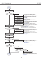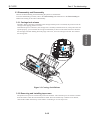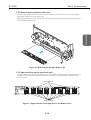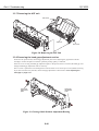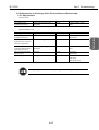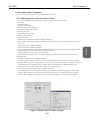
1
REVISION 0 Apr. 2000 QY8-1370-000 COPYRIGHT 2000 CANON INC. CANON BJC-6200 0400 AB 0.20-0 PRINTED IN JAPAN (IMPRIME AU JAPON) 042000 AB 0.20-0 Application This manual has been issued by Canon Inc. for qualified persons to learn technical theory, installation, maintenance, and repair of products. This manual covers all localities where the products are sold. For this reason, there may be information in this manual that does not apply to your locality. Corrections This manual could include technical inaccuracies or typographical errors due to improvements or changes in the products. When changes occur in applicable products or in the content of this manual, Canon will release technical information as the need arises. In the event of major changes in the contents of this manual over a long or short period, Canon will issue a new editions of this manual The following paragraph does not apply to any countries where such provisions are inconsistent with local law. Trademarks The product names and company names described in this manual are the registered trademarks of the individual companies. Copyright This manual is copyrighted with all rights reserved. Under the copyright laws, this manual may not be copied, reproduced or translated into another language, in whole or in part, without the written consent of Canon Inc., except in the case of internal business use. Copyright 2000 by Canon Inc. CANON INC. BJ Printer Technical Support Dept. 11 16-1, Shimonoge 3-chome, Takatsu-ku, Kawasaki, Kanagawa 213-8512, Japan This manual has been produced on an Apple Power Macintosh 7300/180 personal computer and OKI MICROLINE 803 PSIIV laser beam printer; artworks of printing films were printed on Agfa SelectSet Avantra 25. All page layouts, logos, and parts-list data were saved with Canon Optical Disc Subsystem mo-5001S™ and Optical Disc Cartridge mo-502M™, and Interface Kit mo-IF2™ for Macintosh. All graphics were produced with MACROMEDIA FREEHAND™ 7.0J. All documents and all page layouts were created with QuarkXpress™ 3.3 Japanese version. I. ABOUT THIS MANUAL This manual consists of three parts containing information for servicing the product. Product Specifications Part 1: Product Specifications Product overview and specifications. Disassembly and reassembly procedures are not fully covered in this manual. Refer to the separate Parts Catalog instead. I Appendix Part 3: Appendix Block diagrams, information on the hardware technologies, and pin configurations. Troubleshooting Part 2: Troubleshooting A guide to troubleshooting the product and identifying the parts and units needing replacement. Troubleshooting is described according to problem descriptions as well as error indications by the status indicator. II. TABLE OF CONTENTS Page 1- 1 1- 1 1- 2 1- 2 1- 2 1- 2 1- 3 1- 3 1- 3 1- 4 1- 4 1- 5 1- 5 1- 6 1- 7 1- 8 Part 1: PRODUCT SPECIFICATIONS 1. PRODUCT OUTLINE 1.1 Product Outline 2. SPECIFICATIONS 2.1 Printer Specifications 2.1.1 Printer specifications 2.1.2 Printer service life 2.2 Paper Specifications 2.2.1 Paper sizes and weights 2.2.2 Paper types and handling 2.2.3 Printable area 2.3 BJ Cartridge Specifications 2.4 Optional Scanner Cartridge Specifications 2.4.1 Scannable area 2.5 Printer and Scanner Drivers 3. PACKING CONFIGURATION 4. PARTS CODE LIST 2- 1 2- 1 2- 1 2- 2 2- 2 2- 3 2- 6 2- 7 2 -10 2 -10 2 -10 2 -10 2 -10 2 -10 2 -10 2 -11 2 -13 2 -13 2 -13 2 -14 2 -14 2 -15 2 -15 2 -16 2 -16 2 -17 2 -17 2 -18 2 -19 2 -20 2 -20 2 -21 1. PRINTER OPERATION 1.1 Status Indicator 1.1.1 Status display via the indicator 2. SERVICING 2.1 Before Troubleshooting 2.2 Detectable Problems from System Start to Exit 2.3 Troubleshooting Problems 2.4 Troubleshooting With Error Indications 3. DISASSEMBLY AND REASSEMBLY 3.1 Cautions for Disassembly and Reassembly 3.1.1 Ink stains (Ink path/ink mist) 3.1.2 Static electricity damage 3.1.3 Spur tips deformation 3.1.4 Feed gear damage 3.1.5 Tap screw removal and installation 3.2 Exploded View 3.3 Disassembly and Reassembly 3.3.1 Carriage lock release 3.3.2 Removing and installing tap screws 3.3.3 Removing the upper cover unit 3.3.4 Removing the printer unit 3.3.5 Removing the pressure roller unit 3.3.6 Spur positions on the spur base unit 3.3.7 Removing the ASF unit 3.3.8 Removing the head gap adjustment section 3.4 Adjustments and Settings After Disassembly and Reassembly 3.4.1 Adjustments 3.4.2 Applying grease 3.4.3 Print head position adjustment 3.4.4 Setting the EEPROM 3.4.5 Adjusting the carriage belt tension 3.4.6 Adjusting the head gap Part 2: TROUBLESHOOTING II Page 2 -23 2 -23 2 -24 2 -24 2 -25 2 -25 2 -25 2 -25 2 -26 2 -26 2 -26 2 -27 2 -28 2 -28 2 -29 2 -30 2 -31 2 -31 2 -31 2 -31 2 -31 4. OPERATION CHECK AFTER DISASSEMBLY AND REASSEMBLY 4.1 Check Procedure 5. TRANSPORTING THE PRINTER 5.1 Preparation for Transport 6. PARTS REPLACEMENT, PERIODIC INSPECTIONS, & TOOLS 6.1 Parts Replacement 6.2 Periodic Inspections 6.3 Tool List 6.4 Operation with the Printer's Operation Panel 6.4.1 Cleaning 6.4.2 Printing the nozzle check pattern 6.4.3 Roller cleaning 7. SERVICE-RELATED FEATURES 7.1 Service Mode Operations 7.2 Service/Factory Test Printout 7.3 Printing the EEPROM Information 7.4 Resetting the EEPROM 7.5 Setting the Model with the EEPROM 7.6 Ink Availability Check 7.7 Auto Print Head Position Adjustment 7.8 Power Off/Carriage Lock 3- 1 3- 1 3- 2 3- 2 3- 3 3- 3 3- 4 3- 5 3- 5 3- 5 3- 6 3 -10 3 -11 3 -12 3 -13 3 -13 3 -14 3 -14 3 -14 3 -15 3 -15 3 -15 3 -17 1. TECHNICAL REFERENCE 1.1 Print Mode List 1.2 Purge Unit's Capping and Cleaning Functions 1.3 Cautions About the Inks 1.4 Operation with a Computer 1.4.1 Setting functions with the printer driver 1.5 Detection Functions by Sensors 1.6 Electronic Circuit Description 1.6.1 Circuit block diagram 1.6.2 Power source line block diagram 2. CONNECTOR LOCATIONS AND PIN CONFIGURATIONS 2.1 Carriage Board 2.2 BJ Cartridge 2.3 Scanner Cartridge (Optional) 2.4 AC Adapter 2.5 DC Power Cable 2.6 Carriage Motor 2.7 Paper Feed Motor 2.8 ASF Motor 2.9 Ink Sensor 2.10 Printing Position Sensor 2.11 Purge Sensor Connector 2.12 Circuit Diagrams Part 3: APPENDIX III III. ILLUSTRATION INDEX Part 1: PRODUCT SPECIFICATIONS Page 1- 1 1- 4 1- 5 1- 7 Figure Figure Figure Figure 2- 1 2 -11 2 -13 2 -14 2 -14 2 -15 2 -15 2 -16 2 -16 2 -18 2 -19 2 -20 2 -21 2 -22 2 -27 2 -29 2 -30 Figure Figure Figure Figure Figure Figure Figure Figure Figure Figure Figure Figure Figure Figure Figure Figure Figure 1111- 1 2 3 4 Printer Appearance Printable Area Scannable Area Packing Configuration Part 2: TROUBLESHOOTING 2- 1 2- 2 2- 3 2- 4 2- 5 2- 6 2- 7 2- 8 2- 9 2 -10 2 -11 2 -12 2 -13 2 -14 2 -15 2 -16 2 -17 Operation Panel Exploded View Carriage Lock Release Upper Cover Unit Removal and Installation Removing the Printer Unit Removing the Pressure Roller Unit Spur Positions on the Spur Base Unit (Bottom View) Removing the ASF Unit Carriage Shaft Position Adjustment Bearing Applying Grease Print Position Adjustment Pattern Carriage Belt Tension Adjustment Head Gap Adjustment 1 Head Gap Adjustment 2 Nozzle Check Pattern Printout (Color Sample) Service/Factory Test Printout (Sample) EEPROM Information Printout (Sample) Part 3: APPENDIX 3- 3 3- 4 3- 5 3- 5 3- 6 3- 6 3 -10 3 -11 3 -12 3 -13 3 -13 3 -14 3 -14 3 -14 3 -15 3 -15 3 -15 Figure Figure Figure Figure Figure Figure Figure Figure Figure Figure Figure Figure Figure Figure Figure Figure Figure 3- 1 3- 2 3- 3 3- 4 3- 5 3- 6 3- 7 3- 8 3- 9 3 -10 3 -11 3 -12 3 -13 3 -14 3 -15 3 -16 3 -17 Printer Driver Utilities (Sample) Sensor Locations Block Diagram Power Source Line Block Diagram Control Board Printer Diagram Carriage Board BJ Cartridge Scanner Cartridge AC Adapter DC Power Cable Carriage Motor Paper Feed Motor ASF Motor Ink Sensor Print Position Sensor Purge Sensor IV IV. TABLE INDEX Part 1: PRODUCT SPECIFICATIONS Page 1- 8 Table 2- 7 Table 3- 1 3- 2 Table Table 1- 1 PARTS CODE LIST Part 2: TROUBLESHOOTING 2- 1 ERROR INDICATIONS Part 3: APPENDIX 3- 1 3- 2 PRINT MODE LIST INK CONSUMPTION DURING CLEANING (GENERAL GUIDE) V Part 1 PRODUCT SPECIFICATIONS Page 1- 1 1- 1 1- 2 1- 2 1- 3 1- 4 1- 5 1- 6 1- 7 1- 8 1. PRODUCT OUTLINE 1.1 Product Outline 2. SPECIFICATIONS 2.1 Printer Specifications 2.2 Paper Specifications 2.3 BJ Cartridge Specifications 2.4 Optional Scanner Cartridge Specifications 2.5 Printer and Scanner Drivers 3. PACKING CONFIGURATION 4. PARTS CODE LIST Part 1: Product Specifications BJC-6200 1. PRODUCT OUTLINE 1.1 Product Outline "Standard Color Printer for Personal Use" Operation Panel Paper Guide Paper Support Front Cover Auto Sheet Feeder USB Interface Port Paper Output Tray Parallel Interface Port Paper Thickness Lever Cartridge Container Black (Optional) Color BJ Cartridges Photo (Optional) Figure 1-1 Printer Appearance 1-1 Scanner Cartridge (Optional) Product Specifications 1) Dual cartridge system for high-speed monochrome printing and high-speed color printing. 2) Printer cartridge incorporates ink drop modulation technology for high-quality 1440 × 720 dpi printing. 3) Separate ink cartridges and tanks for all colors to reduce running costs. 4) USB interface enables connection to Windows 98/2000, iMac, and Power Macintosh G3/G4 computers. 5) Optional drop-in scanner cartridge. 6) Photo cartridge enables six-color, density-matched photo-quality printing. 7) Black cartridge contains pigment-colored ink for truer black text printing. 8) Highly precision ink-low detection with an optical system and dot count. 9) Stabilized image printing with the easy to use automatic print position adjustment. Part 1: Product Specifications BJC-6200 2. SPECIFICATIONS 2.1 Printer Specifications 2.1.1 Printer specifications Type Paper Feed System Resolution Throughput (Reference only) Printing Direction Max. Printing Width Interface ASF Capacity Sensors Operating Noise Ambient Conditions Power Source External Dimensions Required Space Weight Standard Conformance Desktop serial printer Automatic feed only (No manual feed) 1440 × 720 dpi (Max. resolution) High-speed BC-30 + BC-31 Cartridge Black Text (PC Magazine) New monochrome pattern (J) New color pattern (J) BC-32 Photo + BC-31 Cartridge Full Address Printing 9.6 ppm 10 ppm * 7 ppm * Standard 7.7 ppm 8.3 ppm * 3.7 ppm * - - High-quality 1.7 ppm 2.0 ppm 1.2 ppm 0.14 ppm * * Catalog specification. HS mode (180 × 180 dpi): Bidirectional HQ mode (360 × 360 dpi, 720 × 720 dpi): Unidirectional/Bidirectional Fine mode (360 × 360 dpi, 720 × 720 dpi, 1440 × 1440 dpi): Bidirectional 203 mm USB, IEEE 1284-standard, 8-bit parallel (Compatible/Nibble/ECP) Plain paper: Max. 10 mm (Approx. 100 sheets with 64 g/m2) BJ Printer paper: Max. 10 mm (Approx. 80 sheets of high-quality paper) • Front cover-open sensor • Printing position sensor • BJ cartridge sensor • Paper sensor • BJ cartridge ID sensor • Waste-ink capacity sensor • No-ink sensor • Paper width sensor: None • Internal temperature sensor Approx. 45 dB (A) Sound pressure level conforms to ISO 9296. During operation: Temperature 5°C-35°C (41°F-95°F) Humidity 10%-90% RH (No condensation) During non-operation: Temperature 0°C-35°C (32°F-95°F) Humidity 5%-95% RH (No condensation) Power voltage/frequency Power consumption During standby 100-120 VAC 50/60 Hz Approx. 30 W 3.5 W 220-240 VAC 50/60 Hz Approx. 30 W 3.5 W Approx. 455 mm (W) × 312 mm (D) × 173 mm (H) (With retracted paper support and no output tray.) Approx. 455 mm (W) × 562 mm (D) × 248 mm (H) (With output tray and retracted paper support.) Approx. 4.1 kg Radio-wave interference: FCC, IC, CE Mark, Taiwan EMC, C-Tick, VCCI Electrical safety: UL, C-UL, CB Report, GS, CE Mark, FIMKO, SEMCO, IEC, AS, CCIB, SISIR, Korean Electric Commerce, NEMKO Environmental: Energy Star, Blue Angel 2.1.2 Printer service life The printer's service life extends until any of the following conditions is attained: (1) A total of 20,000 sheets are printed with 1,500 character standard in black ink. (2) A total of 6,000 sheets are printed at 7.5% duty per color. (3) Five years of operation elapses. 1-2 Part 1: Product Specifications BJC-6200 2.2 Paper Specifications 2.2.1 Paper sizes and weights 2.2.2 Paper types and handling Type Plain paper Plain paper for Color BJ High-quality paper Photo glossy paper Glossy film Transparency film Back print film Banner T-shirt transfer Photo glossy card Postcard Envelope LC-301* Size A4/B5/LTR/LGL/ A5 (Portrait/ Landscape) A4/LTR ASF Capacity Paper Thickness Lever Position Approx. 10 mm or less Up (Approx. 100 sheets of 64 g weight) Approx. 10 mm or less Up HR-101* A4/LTR Approx. 10 mm or less Up GP-301* A4/LTR Less than 10 sheets Up HG-201* CF-102* A4/LTR A4/LTR 1 sheet Less than 30 sheets Up Up BF-102* A4/LTR Less than 10 sheets Up BP-101* TR-201* A4/LTR A4/LTR 1 sheet 1 sheet Down Down FM-101* 120 mm × 216 mm 1 sheet Up COM #10 DL-size 100 mm × 148 mm 241 mm × 105 mm 220 mm × 110 mm Less than 40 sheets Less than 10 sheets Less than 10 sheets Up Down Down - * Paper dedicated to BJ printers. If the Paper Thickness Lever is not properly set, problems with paper feeding or printing may occur. 1-3 Product Specifications (1) Paper sizes A4, B5, A5, A5 landscape, letter, legal, envelope (C4 and C6), postcard (2) Weight 64 g - 105 g/m2 for auto feeding Part 1: Product Specifications BJC-6200 2.2.3 Printable area A4/A5/B5/Letter (LTR)/Legal (LGL)/ 3.0mm Envelope 3.0mm 32mm 5.0mm 6.4mm (COM#10: 31.4mm) (DL size: 10.4mm) (2) 26mm (1) 23mm 5.0mm 3.4mm: A4/A5/B5 6.4mm: LTR/ LGL 3.4mm: A4/A5/B5 6.3mm: LTR/ LGL Banner Paper 3mm 3.4mm 1 2 3 4 5 6 3.4mm Max. 6 sheets printable. After printing, the seventh sheet is cut off. 32mm : Recommended printing area : Printable area (1) For monochrome printing. (2) For color or photo-quality printing. Figure 1-2 Printable Area 2.3 BJ Cartridge Specifications Ink colors Tank Black BJ Cartridge BC-30 Detachable ink tank 160 nozzles (Vertical array) Bk (160 nozzles × 1) Pigment black BCI-3BK Color BJ Cartridge BC-31 Detachable ink tank 144 nozzles (Vertical array) C, M, Y (48 nozzles × 3) Dye C, M, Y BCI-3C, BCI-3M, BCI-3Y Weight Service Life Printable Sheets 60 g (w/o ink tank) Approx. 5000 sheets Approx. 500 sheets/tank (1,500 black characters/page) 60 g (w/o ink tank) Approx. 3000 sheets Approx. 280* sheets/tank (7.5% printing per color) Construction Head * Based on the printable area of A4 paper. 1-4 Photo BJ Cartridge BC-32 Photo Detachable ink tank 144 nozzles (Vertical array) Bk, C, M (48 nozzles × 3) Dye PBk, PC, PM BCI-3BK Photo, BCI-3PC Photo, BCI3PM Photo 60 g (w/o ink tank) Approx. 3000 sheets Approx. 280* sheets/tank (7.5% printing per color) Part 1: Product Specifications BJC-6200 2.4 Optional Scanner Cartridge Specifications IS-32 Cartridge replacement type color scanner 90 × 90, 180 × 180, 200 × 180, 300 × 360, 360 × 360, 720 × 720 256-pixel, linear (single line) CCD RGB (Red, Green, Blue) RGB-switching progressive scanning Document inserted in scanning holder and fed via the ASF ECP/Nibble Approx. 41 mm (W) × 90 mm (D) × 77 mm (H) Approx. 100 g Printer setting for scanning: Paper thickness lever must be up. Paper sizes for scanning: A4/LTR size or smaller (with BJ F620) Paper thickness for scanning: 0.25 mm or less Approx. 3 min. 14 sec. (DTP color mode: A4, 180 dpi) Approx. 6 min. 15 sec. (Photo mode: A4, 360 dpi) Scanning Time (reference)* * Measurement Conditions • Computer: Dell XPS T550 (Pentium III 550 MHz, 256MB RAM) • Interface: Parallel interface, ECP mode • Scanning paper size: A4 • The scanning time spans from the start of the carriage scanning operation to the output of the document. 2.4.1 Scannable area When scanning a document, be sure to use the scanning holder to prevent paper jamming. Align the document with the scanning baseline when placing it in the scanning holder. 3.4mm 6mm 32mm Scanning baseline Scanning area Recommended scanning area Document 21mm Scanning holder Figure 1-3 Scannable Area The document sizes and scanning area are listed below. Document Postcard A5 B5 A4** Letter** Size (W × H) mm 100.0 × 148.0 148.0 × 210.0 182.0 × 257.0 210.0 × 297.0 215.9 × 279.4 (8.5 × 11.0 in.) Scannable Area* (W × H) mm 93.2 × 138.0 141.2 × 200.0 175.2 × 247.0 203.2 × 287.0 208.2 × 269.4 ** The actual scannable area may vary slightly depending on the monitor's display resolution and the scanner's scanning resolution. ** If the B5 Scanning Holder (provided with Scanner Cartridge IS-32) is used to scan a large-size document, the optional A4/LTR Scanning Holder (SH-101) will be required. 1-5 Product Specifications Designation Type Resolution (dpi) Imaging Sensor Light Source Scanning System/Direction Document Feeding Interface External Dimensions Weight Other Specifications Part 1: Product Specifications BJC-6200 2.5 Printer and Scanner Drivers The drivers and interface ports that can be used with the printer are listed below. Windows 95/98 Windows NT4.0 Windows 2000 Macintosh Printer Driver Parallel I/F USB I/F ● ▲* ● ✕ ● ●* --●** Scanner Driver Parallel I/F USB I/F ●*** ▲* ●*** ✕ ●*** ●* --●** ●: * ** Compatible. ▲: Conditionally compatible. ✕: Incompatible. For USB, compatibility is assured only with personal computers with Windows 98/2000 preinstalled. Compatible with iMac and Power Macintosh G3. iMac running on Mac OS 8.1 requires iMac updater 1.0. *** Common driver for Windows 95/98/NT 4.0/2000. Operates in Nibble or ECP mode. 1) Window Drivers Win 95/98 BJ raster printer driver (IEEE 1284, 8-bit parallel and USB supported) Win NT 4.0 BJ raster printer driver Win 2000 BJ raster printer driver Windows 95/98/NT 4.0/2000 scanner driver IS Scan 2) Macintosh Drivers Mac BJ printer driver (USB) Mac scanner driver IS Scan (USB) 1-6 Part 1: Product Specifications BJC-6200 3. PACKING CONFIGURATION After opening the package, make sure all the items below have been included. Quick Start Guide Product Specifications Cartridge Container User Manuals Ink Tanks BJ Cartridges Printer Power Cord Output Tray Packing Materials Tape Packing Materials Tape Tape Packing Materials Tape Figure 1-4 Packing Configuration 1-7 Part 1: Product Specifications BJC-6200 4. PARTS CODE LIST A list of printer parts, consumables, and optional equipment are listed below. Table 1-1 PARTS CODE LIST Item Printer BJ cartridge Ink cartridge Cartridge storage box Scanner cartridge A4/LTR scanning holder Black Color Photo Black Cyan Magenta Yellow Photo black Photo cyan Photo magenta Scanning holder Standard white sheet Designation BJC-6200 BC-30 BC-31 BC-32 Photo BCI-1BK BCI-3C BCI-3M BCI-3Y BCI-3PBK Photo BCI-3PC Photo BCI-3PM Photo SB-30 IS-32 SH-101 Product Code Q30-3310 Q30-3312 F45-1471 F45-1481 F45-1501 F47-2171 F47-2181 F47-2191 F47-2201 F47-2231 F47-2211 F47-2221 Q70-4040 Q70-4070 Q70-3640 * Items included with BJC-6200: BC-30, BC-31, BCI-3BK, BCI-3C, BCI-3M, BCI-3Y, SB-30. 1-8 Part 2 TROUBLESHOOTING Page 2- 1 2- 1 2- 2 2- 2 2- 3 2- 6 2- 7 2 -10 2 -10 2 -11 2 -13 2 -17 2 -23 2 -23 2 -24 2 -24 2 -25 2 -25 2 -25 2 -25 2 -26 2 -28 2 -28 2 -29 2 -30 2 -31 2 -31 2 -31 2 -31 2 -31 1. PRINTER OPERATION 1.1 Status Indicator 2. SERVICING 2.1 Before Troubleshooting 2.2 Detectable Problems from System Start to Exit 2.3 Troubleshooting Problems 2.4 Troubleshooting With Error Indications 3. DISASSEMBLY AND REASSEMBLY 3.1 Cautions for Disassembly and Reassembly 3.2 Exploded View 3.3 Disassembly and Reassembly 3.4 Adjustments and Settings After Disassembly and Reassembly 4. OPERATION CHECK AFTER DISASSEMBLY AND REASSEMBLY 4.1 Check Procedure 5. TRANSPORTING THE PRINTER 5.1 Preparation for Transport 6. PARTS REPLACEMENT, PERIODIC INSPECTIONS, & TOOLS 6.1 Parts Replacement 6.2 Periodic Inspections 6.3 Tool List 6.4 Operation with the Printer's Operation Panel 7. SERVICE-RELATED FEATURES 7.1 Service Mode Operations 7.2 Service/Factory Test Printout 7.3 Printing the EEPROM Information 7.4 Resetting the EEPROM 7.5 Setting the Model with the EEPROM 7.6 Ink Availability Check 7.7 Auto Print Head Position Adjustment 7.8 Power Off/Carriage Lock Part 2: Troubleshooting BJC-6200 1. PRINTER OPERATION The printer's operation status is indicated by the status indicator, and the printer can be controlled from the computer or with the printer itself. 1.1 Status Indicator The printer's operation status is indicated by the indicator. When an error occurs, the nature of the error can be known by the number of times the indicator blinks in orange and/or green. Indicator Figure 2-1 Operation Panel 1.1.1 Status display via the indicator The operation status indicated by the indicator is as follows. Indicator Green light Green blinking OFF Operation Status Power ON Power ON operation in progress, power OFF operation in progress, reset operation in progress, cleaning in progress, test printing, front cover open, printing in progress. Power OFF 2-1 Troubleshooting POWER button RESUME button Part 2: Troubleshooting BJC-6200 2. SERVICING 2.1 Before Troubleshooting Before troubleshooting the printer, check the following and see if any of the applicable problems can be fixed. Problem The printer does not operate at all Paper feeding does not work No printing Stripes appear in the printing Probable Cause The power outlet is not supplying the required voltage. The power cord is not properly connected to the printer or power outlet. The power switch is not ON. The recommended paper is not being used. There is foreign matter in the paper feed section (sheet feeder, pinch roller, LF roller, platen, spurs). The paper thickness lever is not set properly. The print head needs cleaning. The ink cartridge is empty. The BJ cartridge has not been used for a prolonged period. The recommended paper is not being used. The print head is installed in the wrong position. The orange tape is still affixed to the print head. The print head position adjustment has not been done. 2-2 Solution Connect the AC cord to a power outlet that supplies the required voltage. Check that the power cord is connected properly. Turn on the power switch. Use the recommended paper. Remove the foreign matter. Set the lever to the proper setting. Conduct cleaning. Replace the ink cartridge. Conduct cleaning. If the problem still persists, replace the BJ cartridge. Use the recommended paper. Install the print head properly. Remove the orange tape. Execute the print head position adjustment. See page 2-19. Part 2: Troubleshooting BJC-6200 2.2 Detectable Problems from System Start to Exit AC power connection AC power supplied MPU & printer controller initialization Troubleshooting ROM check DRAM check Ink sensor check/waste ink-full check/internal temperature sensor (TH501) check Ink sensor error • No error indication EEPROM read Power ON With the POWER button Indicator blinks To next page 2-3 (see page 2-9) Part 2: Troubleshooting BJC-6200 From preceding page Error check Normal? No • Indicator repeats: Blinks 3 times in Yes Diode sensor check Normal? orange/green, then one long blink in green. (See page 2-8) • Indicator repeats: Blinks once in orange, repeatedly. ROM error* (See page 2-8) • Indicator repeats: Blinks 2 times in RAM error* orange, repeatedly. (See page 2-8) • Indicator repeats: Blinks 6 times in Waste ink-full error orange/green, followed by a long blink in green, repeatedly. (See page 2-8) Internal temperature • Indicator repeats: Blinks 5 times in sensor error orange/green, followed by a long blink in green, repeatedly. (See page 2-8) * Any ROM/RAM errors are indicated as described above only during initialization. EEPROM error No • Indicator repeats: Blinks 7 times in Abnormal head temperature error Yes orange/green, followed by a long blink in green, repeatedly. • Indicator repeats: Blinks 8 times in Diode sensor error orange/green, followed by a long blink in green, repeatedly. (See page 2-9) Carriage lock release Home position check Normal? No Yes • Indicator repeats: Blinks 4 times in Home position error orange/green, followed by a long blink in green, repeatedly. (See page 2-8) Paper check Normal? Yes • Is there paper inside the printer? No Paper discharge Paper exists Paper check No paper To next page Paper jam error • Indicator repeats: Blinks 3 times in orange, followed by a long blink in green, repeatedly. (See page 2-7) 2-4 Part 2: Troubleshooting BJC-6200 From preceding page ASF sensor check Normal (ON)? No Yes ASF sensor error BJ cartridge check • Indicator repeats: Blinks 10 times in No Normal? Yes Cleaning • Cartridge installation • Cartridge not recognized • Not installed properly Cover open check Open/ Closed? Closed The sensor will determine if the front cover is open or closed. Open Carriage moves to cartridge replacement position Cartridge installation error I/F busy canceled Ink sensor check No-cartridge error Cartridge error Normal? Ink sensor error I/F busy canceled END 2-5 • Indicator repeats: Blinks 5 times in orange, followed by a long blink in green, repeatedly. (See page 2-7) • Indicator repeats: Blinks 7 times in orange, followed by a long blink in green, repeatedly. (See page 2-7) • Indicator repeats: Blinks 7 times in orange, followed by a long blink in green, repeatedly. (See page 2-7) Troubleshooting orange/green, followed by a long blink in green, repeatedly. (See page 2-9) Part 2: Troubleshooting BJC-6200 2.3 Troubleshooting Problems Problem Power does not come on No printing White stripes or smearing appear Soiled paper Spur tracks appear Broken vertical lines Error does not occur at ink-out Abnormal noise Probable Cause / Check Items AC adapter, control board, DC cable. BJ cartridge, purge unit, ink tank, or orange cap/tape still affixed to print head. BJ cartridge, faulty BJ cartridge contacts, cartridge ribbon cable, purge unit, control board, ink tank. Ink mist, etc., at the platen's paper guide plate is soiling the paper. Check for any ink adhering to the paper transport parts. (The paper is already soiled when it reaches the platen.) Deformed spur tips. Paper thickness lever not properly set. The nozzle check pattern's printout is misaligned. Guide shaft not greased properly. Faulty carriage motor. Ink sensor, control board LF motor 2-step gear, purge unit, sheet feeder unit, orange cap still attached to the print head. 2-6 Solution Replace faulty part. Replace faulty part. Replace faulty part. Use a soft cloth dampened with water to clean. Disassemble the paper transport parts and use a soft cloth dampened with water to clean. Pass several sheets through. Replace the spur unit. Set it to the proper position. Readjust the printing position. Apply proper amount of grease on the stipulated parts. Replace carriage motor. Replace faulty part. Replace faulty part. Part 2: Troubleshooting BJC-6200 2.4 Troubleshooting With Error Indications 1) Error indication when a user-recoverable error occurs The indicator indicates an error by blinking in orange for a certain number of times. After it blinks in orange to indicate the error, it blinks once, long, in green. This indication is repeated. 2) Error indication when an error un-recoverable by the user occurs The indicator indicates an error by blinking alternately in orange and green for a certain number of times. After it blinks in orange and green to indicate the error, it blinks once, long, in green. This indication is repeated. * Table 2-1 ERROR INDICATIONS Indicator Blinking Error Description Code* Probable Cause and Suspected Parts User-Recoverable Errors 2 times in --Paper feed error orange 1 3 times in orange 1 --- Paper jam error 4 times in orange 1 --- Out of ink error 5 times in orange 1 --- Cartridge installation error 6 times in orange 1 7 times in orange 1 --- No-cartridge error --- Cartridge error 1 Cause: Paper feed does not work even when the paper feed operation is attempted. Suspect: Paper feed section, sheet feeder unit, paper-end sensor, control board Cause: The paper is not ejected, even when the paper ejection operation is attempted for 23 inches. Suspect: Paper feed section, paper-end sensor, control board Cause: No ink in the respective ink tank (ink compartment and sponge). Suspect: Ink tank Cause: The wrong cartridge (BJ cartridge or scanner cartridge) is installed in the carriage for printing or scanning. Suspect: BJ cartridge, scanner cartridge Cause: No cartridge has been installed. Suspect: Cause: The cartridge installed is defective. Suspect: BJ cartridge User-recoverable errors are indicated by the specified number of blinks in orange, followed by a long blink in green, repeated. 2-7 Troubleshooting The error code is displayed by the computer. With the iMac and Power Macintosh G3, a "D" or "M" is appended to the beginning of the error code. ** The waste-ink warning can be canceled by pressing the RESUME button. *** Error information for internal errors is not displayed nor indicated. You can check it by printing the EEPROM information. See 7.3 Printing the EEPROM Information on page 2-30. **** If a ROM or RAM error occurs, the error indication might not be correct. Part 2: Troubleshooting BJC-6200 8 times in orange --- Waste-ink warning** 9 times in orange --- Auto Print Position Adjustment 1 Cause: The total waste-ink count recorded in the EEPROM exceeds 95% of the stipulated amount indicating waste-ink full. Suspect: Waste-ink absorber, control board Cause: Auto head position adjustment problem occurred. Suspect: BJ cartridge, ink tank, printing position sensor, control board carriage ribbon cable User-recoverable errors are indicated by the specified number of blinks in orange, followed by a long blink in green, repeated. Non User-Recoverable Errors --ROM error**** 1 time in orange/green --RAM error**** 2 times in orange/green 3 times in orange/green 6800 EEPROM error 4 times in orange/green 5100 Home position error 5 times in orange/green 5400 Internal temperature sensor error 6 times in orange/green 5B00 Waste ink-full error 7 times in orange/green 5200 Abnormal print head temperature error Cause: ROM check failed during initialization. Suspect: ROM, control board Cause: RAM check failed during initialization. Suspect: DRAM, MPU & print controller, control board Cause: EEPROM cannot be written to properly. Suspect: EEPROM, MPU & print controller, control board Cause: The carriage's home position cannot be detected because the home position sensor is faulty (disconnected, etc.). Suspect: Home position sensor, purge unit, carriage motor, paper feed motor, control board, carriage ribbon cable, carriage board, DC cable Cause: The temperature sensor (TH501) on the control board is faulty (disconnected, etc.). Suspect: Thermistor, control board Cause: The waste-ink absorber reached 100% of the waste-ink capacity. Suspect: Waste-ink absorber, control board Solution: Reset the EEPROM, replace waste-ink absorber, replace control board Cause: The print head's temperature is abnormally high. Suspect: BJ cartridge, control board, no ink in ink tank Non User-Recoverable Errors are indicated by the specified number of blinks in orange and green, followed by a long blink in green, repeated. 2-8 Part 2: Troubleshooting BJC-6200 5200 Print head temperature sensor (diode sensor) error 9 times in orange/green 5600 No cartridge error 10 times in orange/green 5700 ASF sensor error 11 times in orange/green 12 times in orange/green 5210 Scanner cartridge error 5000 Recovery system error --- Ink sensor Internal Error No error indication Cause: Faulty temperature sensor in the BJ cartridge. Suspect: BJ cartridge, control board Cause: The cartridge cannot be detected other than at the cartridge replacement position. Suspect: Cartridge, control board, carriage board, carriage ribbon cable. Improper contact between cartridge and carriage. Cause: During the pick-up operation, the pick-up roller does not rotate, or, the pick-up roller sensor cannot detect the pick-up roller flag. Suspect: Sheet feeder unit, purge unit, control board Cause: Faulty data in the scanner cartridge. Suspect: Scanner cartridge, control board Cause: While AP motor or LF motor runs, the PG sensor does not turn ON or OFF. Suspect: Purge unit, AP motor, LF motor, control board Cause: The check by the ink sensor during initialization indicates that ink is available when there is none. The ink sensor does not check the ink until the AC power is turned off. In this case, the ink compartment is always recognized to have ink. Suspect: Control board, ink sensor, ink tank, EEPROM error*** 2-9 Troubleshooting 8 times in orange/green Part 2: Troubleshooting BJC-6200 3. DISASSEMBLY AND REASSEMBLY 3.1 Cautions for Disassembly and Reassembly 3.1.1 Ink stains (Ink path/ink mist) During servicing, be careful not to touch the ink path and get ink stains on the printer, work table, and your hands and clothing. The ink path includes the BJ cartridge's ink tank supply inlet, the BJ cartridge's ink filter, the ink nozzles and maintenance jet receptacle, head cap, wiper, and waste-ink absorber. Also, a printer that has seen long-term use or heavy-duty use may have ink mist soiling the platen, inside the front cover, and purge section. Such soiled parts can soil the paper or your hands and clothing during servicing. To prevent this, use a soft cloth dampened with water to clean the parts thoroughly. 3.1.2 Static electricity damage The rubbing of clothing can build up static electricity within the human body. Static electricity can destroy electrical components or alter the electrical characteristics of components. Never touch the ink sensor's contacts or the contacts on the BJ cartridge on the carriage. 3.1.3 Spur tips deformation Be careful not to deform the spur tips. The spur tips contact the paper after the printing. Since the spur tips' contact area is small, any ink adhering to the spur will be a minuscule amount that can be wiped off by the spur cleaner. It therefore will not soil the paper. However, if the spur's tips are bent of out of shape, the contact area with the paper will be larger, resulting in a larger amount of ink adhering to the spur, which might not be completely cleaned. The spurs will then soil the paper with dotted lines. 3.1.4 Feed gear damage When disassembling or reassembling the printer, do not touch the paper feed gears (feed roller gear and feed drive gear). Note that even a slight scratch on the paper feed gear will cause irregular paper feeding during high-quality printing. 3.1.5 Tap screw removal and installation The printer uses tap screws to fasten the printer unit and base. The removed tap screws will have residue from the mold in which the internal thread was made. Since the residue may crush the screw threads, clean off the residue from the tap screws before re-installing them, or use new tap screws. 2-10 Figure 2-2 Exploded View Troubleshooting 3.2 Exploded View BJC-6200 Part 2: Troubleshooting 2-11 Part 2: Troubleshooting BJC-6200 3.3 Disassembly and Reassembly Cautions for disassembling and reassembling the printer are stated below. As for the disassembly procedure, refer to the Parts Catalog. The illustrations in the Parts Catalog are numbered according to the order of disassembly. 3.3.1 Carriage lock release Normally, when a cartridge is installed on the carriage and the power is turned off, the printer moves the carriage to the capping position to lock it. And when the power is turned on, the carriage lock is normally released. However, if the printer does not operate properly, you can release the carriage lock manually as shown in the illustration below. Remove the cartridge, and while holding down the purge unit's lever, move the carriage to the left. This releases the carriage lock. Troubleshooting Figure 2-3 Carriage Lock Release 3.3.2 Removing and installing tap screws The printer uses tap screws to fasten the printer unit and base. The removed tap screws will have residue from the mold in which the internal thread was made. Since the residue may crush the screw threads, clean off the residue from the tap screws before re-installing or use new tap screws. 2-13 Part 2: Troubleshooting BJC-6200 3.3.3 Removing the upper cover unit To remove the upper cover unit, see the figure below. 1) Unhook the upper cover unit's four hooks on the sides and back. 2) Unhook the two hooks on the front. To reinstall, follow this procedure in reverse. Figure 2-4 Upper Cover Unit Removal and Installation 3.3.4 Removing the printer unit Remove the printer unit as shown in the figure below. 1) First remove the two screws securing the printer unit and bottom case. 2) Release the bottom case's two hooks at the back of the printer unit. (Arrows 1 and 2) 3) Hold the two handles on the sides of the printer unit and lift up at an angle as shown by arrow 3. 3 Screw 3 1 2 Figure 2-5 Removing the Printer Unit 2-14 Part 2: Troubleshooting BJC-6200 3.3.5 Removing the pressure roller unit To remove the pressure roller unit, release the three hooks in turn as shown by the arrows in the figure. Then pull it out from rear of the printer unit. When releasing the hooks, start with the one on the left (when facing the front of the pressure roller unit). This will make removal easier. Troubleshooting Figure 2-6 Removing the Pressure Roller Unit 3.3.6 Spur positions on the spur base unit The figure below shows the position of the spurs on the spur base. The side (bottom) where the spurs are installed is shown. If you removed any of the spurs by mistake, use this diagram to install then at the correct position. Spur positions Spur positions Figure 2-7 Spur Positions on the Spur Base Unit (Bottom View) 2-15 Part 2: Troubleshooting BJC-6200 3.3.7 Removing the ASF unit Set screw ASF unit Set screw Figure 2-8 Removing the ASF Unit 3.3.8 Removing the head gap adjustment section Secured to the printer frame, the head gap adjustment plate is for adjusting the gap between the BJ cartridge's nozzles and platen so that the optimum printing quality is obtained. If the set screw securing the head gap adjustment plate to the printer frame is loosened, the head gap will change and head gap adjustment will be necessary. The set screw is painted in red to distinguish it from the other screws and to prevent accidental loosening. If you have loosened it by mistake, do the head gap adjustment as described in 3.4.6 Adjusting the head gap on page 2-21. Head gap adjustment plate Head gap adjustment plate L Figure 2-9 Carriage Shaft Position Adjustment Bearing 2-16 Part 2: Troubleshooting BJC-6200 3.4 Adjustments and Settings After Disassembly and Reassembly 3.4.1 Adjustments (1) User Level Adjustment BJ cartridge printing position adjustment Timing After BJ cartridge installation/removal Time Required Tools Required 2 min. 2 sheets of B5 or larger paper (2) Serviceman Level Adjustment Belt tension Time Required Tools Required 1 min. Tension spring (QY9-0043) 1 min. None EEPROM setting BJ cartridge printing position adjustment 2 min. 2 sheets of B5 or larger paper Head gap 5 min. See page 2-18 --- Gap gauge (QY9-0038) Grease PG-641 (CK-0562), Floil 946P, brush When applying grease, be careful not to get any grease on the wiper and cap. 2-17 Troubleshooting Timing After idler pulley installation/removal After control board replacement or waste-ink absorber replacement After replacement/disassembly of carriage unit parts After loosening the head gap set screws Parts to be greased Part 2: Troubleshooting BJC-6200 3.4.2 Applying grease Apply the correct grease to the places shown below. Use a flat brush to spread a thin coat of grease. To disassemble and reassemble the printer, refer to the Parts Catalog. When applying grease, be careful not to get any grease on the wiper and cap. Cam friction surface Approx. 27 mg (Molykote PG-641) Pick-up roller friction surface Approx. 7 mg (Molykote PG-641) Carriage shaft friction surface (No dripping) Floil 946P Rear of carriage rail (Apply on entire surface) Approx. 48 mg (Molykote PG-641) Feed roller friction surfaces (Three places on back of platen) Approx. 14 mg x 3 places (Molykote PG-641) Figure 2-10 Applying Grease 2-18 Part 2: Troubleshooting BJC-6200 3.4.3 Print head position adjustment Since the printer has two BJ cartridges installed, the ejected ink's placement can be thrown off due to the differences in the BJ cartridges and the installation conditions. Less than optimum printing quality will result. To eliminate this misalignment, perform the auto print head position adjustment with the printer driver's utility after installing the BJ cartridges. The print head position can also be adjusted in Service Mode with the printer alone, without using a computer. The procedure is described in 7.1 Service Mode Operations on page 2-28. Place one B5 or larger sheet of plain paper in the auto sheet feeder, then start the test printing of the print head position adjustment pattern with the printer driver's utility sheet. Troubleshooting LED Calibration 360 dpi vertical position adjustment 360 dpi bi-directional rough adjustment 360 dpi bi-directional fine adjustment 180 dpi bi-directional rough adjustment 180 dpi bi-directional fine adjustment 360 dpi horizontal position forward direction rough adjustment 360 dpi horizontal position forward direction fine adjustment 360 dpi horizontal position return direction rough adjustment 360 dpi horizontal position return direction fine adjustment 180 dpi horizontal position forward direction rough adjustment 180 dpi horizontal position forward direction fine adjustment 180 dpi horizontal position return direction rough adjustment 180 dpi horizontal position return direction fine adjustment 720 dpi horizontal position forward direction rough adjustment 720 dpi horizontal position forward direction fine adjustment 1440 dpi horizontal position forward direction rough adjustment 1440 dpi horizontal position forward direction fine adjustment Printing position check pattern Figure 2-11 Print Position Adjustment Pattern Printing the nozzle check pattern requires B5 or larger paper. If the paper's width is narrower than the nozzle check pattern, the platen will be printed on and the ink will soil the platen. 2-19 Part 2: Troubleshooting BJC-6200 3.4.4 Setting the EEPROM After replacing the control board or waste-ink absorber, reset the EEPROM, set the model settings, and do a test printout to confirm the settings. The EEPROM (IC502) on the control board stores various printer data such as the waste-ink amount and other printer specific settings. The procedure is described in 7.1 Service Mode Operations on page 2-28. (1) After control board replacement If the waste-ink absorption amount is over 7 percent at the time you replace the control board, also replace the waste-ink absorber. Then reset the EEPROM and restore the printer settings. To check the waste-ink absorption amount, you can either check the service/factory text printout from the old control board or visually check the waste-ink absorber's waste-ink absorption amount. Also, the new control board (EEPROM) data is undefined. The EEPROM must be reset. Otherwise, the waste-ink full error will not occur, even when the wasteink absorber's capacity has been exceeded, thereby leaking ink. (2) After waste-ink absorber replacement Clear the EEPROM's waste-ink counter. Once the data in the EEPROM is reset, a test printout cannot be used to confirm the old data. Be sure to print the data before resetting the EEPROM. The various settings (except the model setting), sheet count, and waste-ink amount will be reset. The various settings and waste-ink amount stored in the old EEPROM cannot be written to the new (replacement) EEPROM. The waste-ink full error is expected to occur only when the printer prints more than the number of sheets specified for its service life. However, how soon this error occurs varies depending on how many times the printer has been turned on/off, the number of times the BJ cartridge has been replaced (front cover open/closing), and the operating environment. 3.4.5 Adjusting the carriage belt tension If the carriage belt tension has been loosened to remove the carriage, etc., adjust the carriage belt tension. When securing the pulley assembly, use the tension spring (QY9-0043) and tighten the screws. After tightening the screws, remove the tension spring. Screws Tension spring Idler pulley Figure 2-12 Carriage Belt Tension Adjustment 2-20 Part 2: Troubleshooting BJC-6200 3.4.6 Adjusting the head gap If the set screws securing the head gap adjustment plate to the printer frame are loosened or removed, the head gap adjustment will be necessary. Preparation 1) Remove the upper cover unit and bottom case. (Or, reassemble the printer so that the upper cover unit and bottom case are to be attached next.) 2) Remove the paper thickness lever spring and the left and right shaft clips, then attach the bottom case. 3) Loosen the red set screws on both sides of the printer chassis by a half rotation from the fully tightened position. 4) Set the paper thickness lever to the down position (for thick paper). Red set screw Head gap adjustment plate (right side) Shaft clip Carriage belt Head gap adjustment plate (left side) Red set screw Black BJ cartridge Paper thickness lever Normal paper position Thick paper position Paper thickness lever spring Figure 2-13 Head Gap Adjustment 1 2-21 Troubleshooting Before doing the adjustment, make sure the gap gauge is not deformed and that no foreign matter is adhering to it or to the platen. Part 2: Troubleshooting BJC-6200 Adjustment Procedure 1) Set the gap gauge (QY9-0038) to position A1. 2) Move the carriage belt by hand so that the carriage goes to position A2. Align the bottom case's rib with the carriage's right end. 3) Install a black BJ cartridge without ink tank in the carriage. 4) Move the paper thickness lever up and down two or three times, then, while holding the lever in the normal paper (up) position, tighten the red set screw on the right end. 5) Remove the black BJ cartridge. 6) Place the gap gauge at position B1. 7) Set the paper thickness lever to the thick paper (down) position. 8) Move the carriage belt by hand so that the carriage goes to position B2. Align the ink sensor's edge with the carriage's left end. 9) Install a black BJ cartridge without ink tank in the carriage. 10) Move the paper thickness lever up and down two or three times, then while holding the lever in the normal paper (up) position, tighten the red set screw on the left end. 11) Remove the black BJ cartridge. 12) Loosen the red set screw on the right end by a half turn. Then repeat steps 1) to 5) to complete the adjustment. Remove the bottom case and attach the paper thickness lever spring and the left and right shaft clips. Position A1 Position A2 QY9-0054 QY9-0038 Align the bottom case's rib with the carriage's right end. Position B2 Position B1 QY9-0054 QY9-0038 Align the ink sensor cover's edge with the carriage's left end. Figure 2-14 Head Gap Adjustment 2 2-22 Part 2: Troubleshooting BJC-6200 4. OPERATION CHECK AFTER DISASSEMBLY AND REASSEMBLY 4.1 Check Procedure After disassembly and reassembly, follow the procedure below to check the printer's operation. 1) After service/factory test printout with the printer alone Check that the printer can print properly. The procedure is described in 7.1 Service Mode Operations on page 2-28. After replacing the control board or the ink absorber, the following check procedure is also necessary in addition to 1) above. After waste ink absorber replacement The service/factory test printout must show the correct ROM version and model designation. It must also show the printed sheet count and that the total waste-ink amount has been cleared. The printer driver must be able to print the nozzle check pattern. The service/factory test printout must show that the total waste-ink amount has been cleared. 2-23 Troubleshooting After control board replacement Part 2: Troubleshooting BJC-6200 5. TRANSPORTING THE PRINTER Before moving or transporting the printer, put one BJ cartridge (with the ink tank installed) in the cartridge container. This is to prevent the ink from leaking and the BJ cartridge's ink nozzles from drying up. Before returning the repaired printer back to the customer, move the carriage to the cartridge replacement position and tape it at that position. 5.1 Preparation for Transport When transporting the printer, follow the procedure below. 1) With the printer turned on, open the front cover and move the carriage to the cartridge replacement position. 2) Remove one cartridge from the carriage and put it in the cartridge container. 3) Turn off the printer by pressing the POWER button. 4) Then, from Service Mode, conduct the power off/carriage lock procedure. For details, refer to 7.1 Service Mode Operations on page 2-28. 5) Disconnect the interface cable (s). 6) Disconnect the AC plug from the power outlet. 7) Close the front cover. 8) Pack the printer in its original packaging. If you do not have the original packaging, use sufficient cushioning material when packing the printer. 2-24 Part 2: Troubleshooting BJC-6200 6. PARTS REPLACEMENT, PERIODIC INSPECTIONS, & TOOLS 6.1 Parts Replacement Level User Serviceman Level User Consumables Black BJ cartridge: BC-30 Color BJ cartridge: BC-31 Photo BJ cartridge: BC-32 Black BJ cartridge ink tank (Black: BCI-3BK) Color BJ cartridge ink tank (Black: BCI-3BK, Cyan: BCI-3C, Magenta: BCI-3M, Yellow: BCI-3Y) Photo BJ cartridge ink tank (Black: BCI-3BK Photo, Cyan: BCI-3C Photo, Magenta: BCI-3M Photo) None 6.2 Periodic Inspections Level User Serviceman Periodic Inspections None None 6.3 Tool List Ordinary Tools Phillips screwdriver Blade screwdriver Needle-nosed pliers Tweezers Flat brush Multi-meter Remarks For the removal and installation of screws. For the removal of plastic parts. For the removal and installation of springs. For the disconnection and connection of flexible cables, etc. For applying grease. For troubleshooting. Special Tools (Part No.) Gap gauge 2.3 mm (QY9-0054-000) Tension spring (QY9-0043-000) Grease Molykote PG-641 (CK-0562-000) Grease FLOIL 946P (QY9-0045-000) Remarks For Head gap adjustment (see Figure 2-14 on page 2-22). Use 1. For carriage belt tension adjustment (see Figure 2-12 on page 2-20). To be applied on the specified parts (see Figure 2-10 on page 2-18). To be applied on the specified parts (see Figure 2-10 on page 2-18). 2-25 Troubleshooting Serviceman Periodically Replaced Parts None None Part 2: Troubleshooting BJC-6200 6.4 Operation with the Printer's Operation Panel The printer can be operated in the offline operation mode, with the power turned on and without connection to a computer. With the printer turned on, you can start various printer operations by holding down the RESUME button and releasing after the green indicator blinks the stipulated number of times. Operation Cleaning Nozzle check pattern printout Roller cleaning --- Indicator Blinking 1 time 2 times 3 times 4 times Remarks --Stops after 1 sheet is printed. Passes one cleaning sheet through. No operation executed. 6.4.1 Cleaning With the printer turned on, hold down the RESUME button and release after the green indicator blinks once. The cleaning will then start. Cleaning can also be performed from the printer driver's utility, while connected to a computer. 6.4.2 Printing the nozzle check pattern With the printer turned on, hold down the RESUME button and release after the green indicator blinks twice. The printer will then start printing the nozzle check pattern. If any printing defects appear in the test printout, clean the BJ cartridges. If printing defects persist even after cleaning the BJ cartridges five times or more, replace the BJ cartridges. Printing the nozzle check pattern requires B5 or larger paper. If the paper's width is narrower than the nozzle check pattern, the platen will be printed on and the ink will soil the platen. To stop the printing of the test pattern midway, press the POWER button. The printing will stop and the sheet will be discharged. Then the printer will turn off. 2-26 Part 2: Troubleshooting BJC-6200 Black BJ cartridge Color BJ cartridge Large-dot printing by the 1st nozzle Large-dot printing Large-dot printing by the 1st nozzle Black Yellow 48 nozzles Cyan 48 nozzles Magenta 48 nozzles 160 nozzles Large-dot printing by the 48th nozzle Large-dot printing by the 160th nozzle Small-dot printing Small-dot printing by the 1st nozzle Small-dot printing by the 1st nozzle Small-dot printing by the 160th nozzle (Y) 180 dpi horizontal position forward direction (X1) 180 dpi horizontal position return direction (X2) 360 dpi horizontal position forward direction (X3) 360 dpi horizontal position return direction (X4) 720 dpi horizontal position forward direction (X5) 720 dpi horizontal position return direction (X6) 180 dpi bi-directional (B1) 360 dpi bi-directional (B2) Figure 2-15 Nozzle Check Pattern Printout (Color Sample) 6.4.3 Roller cleaning With the printer turned on, hold down the RESUME button and release after the green indicator blinks three times. The roller cleaning will then start. The cleaning sheet placed in the auto sheet feeder will be sent through, and the paper fibers, etc., will be cleaned from the pick-up rollers and paper feed rollers. 2-27 Troubleshooting 360 dpi vertical position Small-dot printing by the 48th nozzle Part 2: Troubleshooting BJC-6200 7. SERVICE-RELATED FEATURES The printer has a Service Mode for accessing service settings and executing test printouts. The operations can be selected via the operation panel buttons. 7.1 Service Mode Operations 1) With the printer turned off, hold down the RESUME button and press and hold the POWER button (the green indicator lights). 2) While holding down POWER button, release the RESUME button and then press the RESUME button twice in succession. Then release both the RESUME button and POWER button. (Each time the RESUME button is pressed, the indicator's color toggles between orange and green.) 3) During the printer initialization, the green indicator blinks. When the green indicator stops blinking and lights on, press the RESUME button the stipulated number of times to execute the desired operation listed below. (Each time the RESUME button is pressed, the indicator's color toggles between orange and green.) Press 0 times 1 time 2 times Indicator Lights in green Lights in orange Lights in green Function Service/factory test printout EEPROM information printout EEPROM initialization (All the information will be reset to the default, except for the model setting.) 3 times 4 times 5 times 6 times 7 times or more Lights in orange Lights in green Lights in orange Lights in green Lights in orange Clears the waste-ink counter Model setting*: The setting procedure is described below. Ink availability check and print Auto print head position adjustment Power off/Carriage lock 4) After making the selection, press the POWER button. The green indicator lights and the function will be executed. (After the function is executed, the printer will power off.) * After selecting model setting, press the RESUME button the number of times indicated below to set the product type. (During the initialization, the green indicator blinks. Each time the RESUME button is pressed, the indicator's color toggles between orange and green.) Press 0 times 1 time 2 times or more Indicator Lights in green Lights in orange --- Function BJ F620 (Japan) BJC-6200 (All other countries) Saved as a reserved area where the setting will not be rewritten. After selecting the model, press the POWER button to finalize the setting. (After the printer executes the function, it will turn off.) Before entering the service mode, install the BJ cartridges. The service mode cannot be executed without the cartridges installed. After setting the model, confirm the setting with the service/factory test printout. 2-28 Part 2: Troubleshooting BJC-6200 7.2 Service/Factory Test Printout The header of the service/factory test printout shows the control ROM version, model setting, total printed sheet count, total waste-ink absorption amount, and other information. Total printed sheet count with photo/color BJ cartridge Installed cartridges Model designation ROM version Total printed sheet count with black/color BJ cartridge Unused Unused Total passed sheet count with scanner cartridge ROM Ver Vx.xx BJC-6200 Use Head <BC-30,BC-31> HeadTemp0=031.0 HeadTemp1=032.5 EnvironmentTemp=031.0 Bk=00000 C1=00257 Ph=00000 Sc=00000 ScC1=00000 Factory Area=01 00 00 00 00 01 1B 89 LostInkCount =03.9% Destination =01 USBSerialNo=(109BNF) Figure 2-16 Service/Factory Test Printout (Sample) * USB serial No. If multiple BJS-6200 printers are connected via USB, each printer will have a unique USB serial No. (in accordance with USB standards) so that the computer can distinguish between them. The unique USB serial No. is written in the EEPROM when the control board is manufactured. The USB serial No. written in the EEPROM is not cleared even when the EEPROM is reset. Also, the USB serial No. cannot be modified. 2-29 Troubleshooting Serial No.* for USB Total waste-ink amount (Waste-ink absorber's absorption capacity: %) Part 2: Troubleshooting BJC-6200 7.3 Printing the EEPROM Information The EEPROM stores information such as the various settings; the total printed sheet count of the black, color, and photo BJ cartridges and scanner cartridge; the total waste-ink absorption amount; and the error history of the last three non user-recoverable errors. The information stored in the EEPROM is printed in the hexadecimal dump format in the EEPROM information printout. The EEPROM information serves as a general guide to how much the printer has been used. - EEPROM Information <Hex.> Address +0 +1 +2 +3 +4 00000000 05 20 00 0A 00 00000010 00 00 00 00 2A 00000020 35 6C B7 AB 33 00000030 14 00 0A 07 04 00000040 04 90 00 08 00 00000050 00 00 00 00 00 00000060 00 00 00 1D 00 00000070 00 00 00 00 00 00000080 00 00 00 72 00 00000090 3C 00 00 10 10 000000A0 0C 04 00 08 00 000000B0 00 00 00 00 04 000000C0 00 00 00 00 15 000000D0 04 19 57 AB 98 000000E0 35 36 30 30 35 000000F0 00 00 00 D6 67 +5 00 6A BC 02 00 00 58 00 00 0C 0C 04 0B 1A 36 7C +6 B8 51 E9 02 00 04 00 00 00 0C 0C 00 BB 72 30 73 +7 83 A1 71 02 44 44 1B 08 2E 08 00 00 19 13 30 FF +8 00 38 32 00 00 00 00 00 00 0C FD 00 35 00 35 01 +9 0C 54 DD 00 00 00 01 00 00 10 07 00 1A 45 36 FF +A 9F AA 02 00 00 00 00 00 00 0C 00 00 D5 93 30 FF +B 40 A0 0C 00 44 00 2F 08 30 0C 00 00 C6 6B 30 FF +C 09 1E 00 0A 00 00 00 00 83 0C 04 00 13 46 FF FF +D 35 16 00 80 00 00 06 00 00 10 04 00 0A 34 FF FF +E 1C DA 00 00 00 02 00 00 00 0C 00 00 46 63 FF FF +F 28 3C 00 00 44 B9 00 08 00 0C 00 00 61 E3 F0 FF Error history 1 Error history 2 Error history 3 Figure 2-17 EEPROM Information Printout (Sample) The error history records the last three (starting with the most recent one) non user-recoverable errors that have occurred. It does not include ROM/RAM errors. The error codes are shown in ASCII format. Error Error Code ASCII Code Carriage error 5100 35 31 30 30 Abnormal head temperature 5200 35 32 30 30 Scanner cartridge error 5210 35 32 31 30 Abnormal internal temperature error 5400 35 34 30 30 No head error (in operation) 5600 35 36 30 30 ASF sensor error 5700 35 37 30 30 Ink sensor error 5910 35 39 31 30 Waste-ink full error 5B00 35 42 30 30 Pump sensor error 5C00 35 43 30 30 EEPROM Read/Write error 6800 36 38 30 30 2-30 Part 2: Troubleshooting BJC-6200 7.4 Resetting the EEPROM The EEPROM stores information such as the various settings; the total printed sheet count of the black, color, and photo BJ cartridges and scanner cartridge; the total waste-ink absorption amount; and the error history of the last three non user-recoverable errors. The printer uses the total waste-ink absorption amount recorded by the EEPROM as the basis for determining whether the waste ink is full. Therefore, after replacing the waste-ink absorber, be sure to reset the EEPROM's total waste-ink absorption amount. Also, after replacing the control board, be sure to reset the new control board's EEPROM and to also replace the waste-ink absorber. 7.5 Setting the Model with the EEPROM 7.6 Ink Availability Check When this function is selected, the printer scans the carriage to check for ink in the ink tank's ink compartments. The result is printed out. Whether the ink sensor is working properly can be confirmed by: (1) Installing an empty ink tank in the BJ cartridge. (2) Using this Service Mode function and print out the results. (3) Checking that the "ExistInk" value is 0 (indicating an empty ink tank). 7.7 Auto Print Head Position Adjustment The print head position can be adjusted with the printer alone, without connection to a computer. The adjustment is the same as when the user executes the auto printing position adjustment via the computer. For details on the head printing position adjustment, see 3.4.3 Print head position adjustment on page 2-19. 7.8 Power Off/Carriage Lock When this function is selected, the printer moves the carriage (whether BJ cartridges are installed or not) to the home position and locks the carriage. Then the power turns off. 2-31 Troubleshooting The control board used in the BJC-6200 is also used in other printers. After replacing the control board, the default information for the respective printer must be set. After setting the model, confirm it with the service/factory test printout. Part 2: Troubleshooting BJC-6200 This page intentionally left blank 2-32 Part 3 APPENDIX Page 3- 1 3- 1 3- 2 3- 2 3- 3 3- 4 3- 5 3- 6 3 -10 3 -11 3 -12 3 -13 3 -13 3 -14 3 -14 3 -14 3 -15 3 -15 3 -15 3 -17 1. TECHNICAL REFERENCE 1.1 Print Mode List 1.2 Purge Unit's Capping and Cleaning Functions 1.3 Cautions About the Inks 1.4 Operation with a Computer 1.5 Detection Functions by Sensors 1.6 Electronic Circuit Description 2. CONNECTOR LOCATIONS AND PIN CONFIGURATIONS 2.1 Carriage Board 2.2 BJ Cartridge 2.3 Scanner Cartridge (Optional) 2.4 AC Adapter 2.5 DC Power Cable 2.6 Carriage Motor 2.7 Paper Feed Motor 2.8 ASF Motor 2.9 Ink Sensor 2.10 Printing Position Sensor 2.11 Purge Sensor Connector 2.12 Circuit Diagrams Part 3: Appendix BJC-6200 1. TECHNICAL REFERENCE 1.1 Print Mode List The print mode list for the black, color, and photo BJ cartridges is shown below. By setting the printer driver's "Dithering," "Paper Type," and "Printing Quality" settings, the printer will operate in the printing modes below. Table 3-1 PRINT MODE LIST Black/Color Cartridge Printing Quality Dithering Paper Type Error Dispersion Pattern (High speed) Auto Standard (Faster Speed) Standard (Higher Quality) High Quality Highest Quality 180 × 180 L/R 360 × 360 L/R 360 × 360 L/S/R 720 × 720 S/R 1440 × 720 S/R Plain paper --- 1 pass/bi-directional 2 passes/uni-directional 4 passes/uni-directional --- High quality --- 2 passes/bi-directional 3 passes/uni-directional (4 passes) 4 passes/uni-directional 4 passes/uni-directional Glossy --- --- 4 passes/uni-directional 6 passes/uni-directional (8 passes) 6 passes/uni-directional (8 passes) Glossy film --- --- 4 passes/uni-directional 6 passes/uni-directional (8 passes) --- Photo card --- --- 3 passes/uni-directional 4 passes/uni-directional 4 passes/uni-directional T-shirt transfer --- --- 6 passes/uni-directional --- --- Back print film --- --- 6 passes/uni-directional L/L --- --- Transparency --- 2 passes/uni-directional 4 passes/uni-directional L/L --- --- Envelope --- 1 passes/uni-directional 3 passes/uni-directional (4 passes) 4 passes/uni-directional --- Plain paper 1 pass/bi-directional 1 pass/bi-directional --- --- --- High quality --- 2 passes/bi-directional --- --- --- Envelope --- 1 pass/uni-directional --- --- --- Plain paper 1 pass/bi-directional 1 pass/bi-directional --- --- --- High quality --- 2 passes/bi-directional --- --- --- Plain paper 1 pass/bi-directional 1 pass/bi-directional --- --- --- High quality --- 2 passes/bi-directional --- --- --- Paper Type High-speed Standard (Faster Speed) Standard (Higher Quality) High Quality Highest Quality 180 × 180 L/R 360 × 360 L/R 360 × 360 L/L/R 360 × 360 L/S/P 720 × 720 S/P Photo/Color Cartridge Printing Quality Dithering Error Dispersion Pattern Plain paper --- 1 pass/bi-directional --- 2 passes/uni-directional 4 passes/uni-directional High quality --- 2 passes/bi-directional --- 3 passes/uni-directional 4 passes/uni-directional Glossy --- --- --- 4 passes/uni-directional 6 passes/uni-directional Glossy film --- --- --- 4 passes/uni-directional 6 passes/uni-directional Photo card --- --- --- 3 passes/uni-directional 4 passes/uni-directional T-shirt transfer --- --- 6 passes/uni-directional --- --- Back print film --- --- 6 passes/uni-directional --- --- Transparency --- 2 passes/uni-directional 4 passes/uni-directional --- --- Envelope --- 1 pass/uni-directional --- 3 passes/uni-directional 4 passes/uni-directional Plain paper 1 pass/bi-directional 1 pass/bi-directional --- --- --- High quality --- 2 passes/bi-directional --- --- --- Postcard --- 1 pass/uni-directional --- --- --- Envelope --- 1 pass/uni-directional --- --- --- Note 1: R and P indicate the ink used for printing. R is color inks (4 colors), and P is the photo inks (6 colors). Note 2: L (large) and S (small) indicate the ink's dot size for multi-drop printing. Note 3: The table also indicates the number of passes and the printing direction. If the number of passes differ in the gray scale mode, it is indicated in parentheses. 3-1 Appendix Pattern High-speed Part 3: Appendix BJC-6200 1.2 Purge Unit's Capping and Cleaning Functions Capping is executed at the following times: • When the power is turned off with the POWER button. • When uncapped and print signals have not been received within the stipulated time during standby. During paper feeding: After 20 min. Other times: After 30 sec. • After the front cover has been left open for 10 minutes. Cleaning is executed at the times listed in the table below. As ink suction is performed on both BJ cartridges simultaneously, ink suction for only one BJ cartridge is not possible. Table 3-2 INK CONSUMPTION DURING CLEANING (GENERAL GUIDE) Ink Consumption (approx. mg) Black Color Photo Color 0.39 0.53 0.52 0.72 0.20 0.27 0.30 0.41 0.20 0.27 0.30 0.41 0.20 0.27 0.30 0.41 0.20 0.27 0.30 0.41 0.20 0.27 0.30 0.41 Printer Status Print head refreshing via the printer driver. Cleaning executed via the printer driver. Operation executed via printer's button. 72 hours or more elapsed since the last cleaning. The printed dot count exceeds the stipulated dot count. Before a banner is printed (the dot count since the last cleaning exceeds the stipulated dot count, or the time since the last cleaning exceeds the stipulated time). Power is turned on (for the first time). 0.58 0.79 0.77 1.07 Power is turned on (uncapped after AC connection). 0.39 0.53 0.52 0.72 * Power is turned on (capped after AC connection). 0.20 0.27 0.30 0.41 * At replacement of the BJ cartridge or ink tank. 0.39 0.53 0.52 0.72 * In this case, cleaning is not immediately executed. Cleaning is executed the next time any of following is executed: Printing starts, soft power on, paper feeding, paper ejection. (Reason: When the preconditions for cleaning overlap, delaying the cleaning results in the cleaning being executed only once, reducing ink consumption.) 1.3 Cautions About the Inks Although the inks do not contain any substances harmful to humans, they do contain organic solvents. 1) Black ink Contains glycerin 56-81-5 and diethylene glycol 111-46-6. 2) Yellow ink Contains glycerin 56-81-5 and isopropyl alcohol 67-63-0. 3) Cyan, magenta, photo cyan, photo magenta, photo black inks Contain glycerin 56-81-5, isopropyl alcohol 67-63-0, ethylene glycol 107-21-1, and diethylene glycol 111-46-6. Do not consume the inks or get it into your eyes. Should ink get into your eyes, rinse with lots of water and consult a doctor. Should a large amount of ink be consumed by mistake, promptly see a doctor. Since the inks contain pigments, they will permanently stain clothing. 3-2 Part 3: Appendix BJC-6200 1.4 Operation with a Computer You can set the printer's functions via the dedicated printer driver. 1.4.1 Setting functions with the printer driver Figure 3-1 Printer Driver Utilities (Sample) 3-3 Appendix You can use the dedicated printer driver's utilities to set or execute the following: 1) Cleaning 2) Head refreshing 3) Pick-up roller cleaning 4) Nozzle check pattern printout 5) Print head position adjustment 6) Printer power off 7) Automatic power setting 8) Status monitor startup 9) Special settings • Set the printer to ECP mode (Factory default: Disabled) • High-speed printing (Factory default: Enabled): Sets the printer's response time (ACKNLG) from 4 ms to 0.9 ms. • Pause page (Factory default: Disabled) • Pause scan (Factory default: Disabled) • Execute automatic head position adjustment after BJ cartridge replacement (Factory default: Disabled) • Adjust head position manually (Factory default: Disabled) <<Special Menu for Users (User or Service Mode)>> The Special Menu for users can be accessed by holding down the Shift key and clicking the Custom Settings button. • Economy Cleaning (Factory default: Disabled) The cleaning operations after the AC power is connected and the power turned on for the first time is disabled. When the printer is being repaired or when it turns on in tandem with the computer turning on, the subsequent ink consumption can be reduced. However, this function is disabled if the power is turned on and over 72 hours elapse after the AC power supply is active. • Prevent inter-sheet ink transfer (Factory default: Disabled) The ink transfer control prevents ink smearing caused by paper chafing during paper discharge when the black BJ cartridge is used for high-duty printing on plain paper. This ink transfer control can be disabled. The discharged printed sheets can be removed individually to prevent lower throughput. Part 3: Appendix BJC-6200 1.5 Detection Functions by Sensors The printer has the following sensors to detect the printer's operating status. Internal temperature sensor Ink sensor Pick-up roller sensor Paper-end sensor Home position sensor (Carriage unit) Printing position sensor (Carriage unit) Figure 3-2 Sensor Locations 3-4 Purge sensor (Purge unit) Part 3: Appendix BJC-6200 1.6 Electronic Circuit Description 1.6.1 Circuit block diagram A block diagram of the printer's electronic circuit comprising the control board and carriage board is shown below. Control Board Address bus ROM A0 - A19 48MHz (X101) DRAM (IC103) MA0-9 16-Mbit Parallel interface (CN304) RAM_A0-9 A0-9 POWER switch (SW401) RESUME switch (SW402) PO0/INTP100 Front cover switch (SW403) PO2/INTP102 MPU & Printer Controller (IC101) MD0-15 PO1/INTP101 Power indicator Error indicator (LED401) PA0 PA1 Ink sensor (CN401 ← Ink sensor) ANI5 Purge sensor (CN402 ← Purge sensor) PC3 ST1/TST2 ST2/SOT ST3 ST4/TST3 ST5/TST4 ST6/TST5 EEPROM (IC402) Driver IC (IC401) Driver IC (IC503) A0-19 2 Kbit PM Carriage motor PM Paper feed motor PM ASF motor PC1 Paper-end sensor (PS401) PC2 Pick-up roller sensor (PS402) PC0 ANI1 Appendix Internal temperature sensor (TH401) PB1-3 CR_CLK CR_STB CR_DATA LF_CLK LF_STB LF_DATA PD2 8-Mbit D0-15 RAM_D0-15 D0-15 CE CS0X Control ROM (C102) ROM_D0-15 XT1 XT2 Data bus ROM D0 - D15 ROM_A0-19 USB interface (CN305) RESETX DC/DC converter & reset IC (IC501) P04/PWM1 ANI3 HDATA0,1 HCLOCK0,1 HRSTX HLAT DIR HSEL1A0,1 HSEL1B0,1 HSEL2A0,1 HSEL2B0,1 ODD,EVEN BENB0,1 HENB0-5 SUBH0,1 DIA0,1 DIK0,1 *DTCK *ST0 *LNST *RST *SCHKR HVH HVDD *DIA *DIK *RWR *REN *RDT * Signal name when a scanner cartridge is used. Carriage board *VHLED *VDD Cartridge connector BJ cartridge or scanner cartridge (optional) Home position sensor (PS1) Printing position sensor (CN6 ← Printing position sensor) BJ cartridge Figure 3-3 Block Diagram 1.6.2 Power source line block diagram Motor driver (IC401) Motor driver (IC503) +24 VDC +24 VDC +5 VDC Carriage motor (CN502) Paper feed motor (CN503) ASF motor (CN504) +24 VDC EEPROM (IC402) Control ROM (IC102) OP amp (IC201) DRAM (IC103) Q204: Cartridge (CN201) Thermistor (TH401) MPU & Printer Controller (IC101) Power source input connector (CN501) +24 VDC DC/DC converter & reset IC (IC501) AC in AC adapter The printer uses an internal power voltage of 5 V/24 V/3.3 V. The power source line's block diagram is shown below. +5 VDC Q203: Printing position sensor (CN202) Q401: Parallel interface (CN304) Q402: HP sensor (CN202) Q402: Pick-up roller sensor (PS402) Q402: Paper-end sensor (PS401) Q402: Purge sensor (CN402) Q403: Cartridge (CN203) Q404: Ink sensor (CN401) +3.3 VDC Q301: USB interface (CN305) +3.3 VDC Figure 3-4 Power Source Line Block Diagram 3-5 Part 3: Appendix BJC-6200 2. CONNECTOR LOCATIONS AND PIN CONFIGURATIONS CN305 CN501 5 1 CN402 3 1 1 CN401 1 3 1 1 4 CN502 28 28 1 19 18 36 3 CN304 1 2 CN203 4 CN202 1 CN504 CN201 1 4 20 1 4 CN503 Figure 3-5 Control Board Paper feed/suction drive switching section ASF unit BJ cartridge or scanner cartridge (optional) BJ cartridge CN4 CN5 Paper-feed rollers ASF/wiper drive switching section CN1 Paper-feed motor ASF motor Purge sensor CN402 CN504 CN503 AC adapter CN501 Carriage unit CN2 Ink sensor CN502 CN401 CN201 CN203 CN202 Pick-up roller sensor Mechanical control +24V DC +5V DC +3.3V DC Interface control Parallel USB CN304 CN305 Indicator control Switch detection Indicator Control button Front cover switch Figure 3-6 Printer Diagram 3-6 Print position sensor CN6 Carriage motor Motor control AC CN3 Home position sensor Paper-end sensor Internal temperature sensor Purge unit Control Section Part 3: Appendix BJC-6200 CN304 (Parallel Interface Connector) Compatible Mode STROBE DATA1 DATA2 DATA3 DATA4 DATA5 DATA6 DATA7 DATA8 ACKNLG BUSY P.E. SELECT AUTO FEED XT N.C. GND GND +5.0V STROBE-RET (GND) DATA1-RET (GND) DATA2-RET (GND) DATA3-RET (GND) DATA4-RET (GND) DATA5-RET (GND) DATA6-RET (GND) DATA7-RET (GND) DATA8-RET (GND) ACKNLG-RET (GND) BUSY-RET (GND) P.E.-RET (GND) INIT ERROR GND N.C +5.0V SELECT IN Nibble Mode HostClk Data1 Data2 Data3 Data4 Data5 Data6 Data7 Data8 PrtClk PrtBusy AckDataReq Xflag HostBusy Undefined Gnd Gnd Vcc Signal Gnd Signal Gnd Signal Gnd Signal Gnd Signal Gnd Signal Gnd Signal Gnd Signal Gnd Signal Gnd Signal Gnd Signal Gnd Signal Gnd INIT DataAvail Undefined Undefined Undefined 1284Active CN305 (USB Interface Connector) Pin No. 1 2 3 4 Signal PWR DD+ GND IN/OUT Function IN Cable power source Data Data ... Cable GND 3-7 ECP Mode HostClk Data1 Data2 Data3 Data4 Data5 Data6 Data7 Data8 PeriphClk PeriphAck AckReverse Xflag HostAck Undefined Gnd Gnd Vcc Signal Gnd Signal Gnd Signal Gnd Signal Gnd Signal Gnd Signal Gnd Signal Gnd Signal Gnd Signal Gnd Signal Gnd Signal Gnd Signal Gnd ReverseReq PeriphReq Undefined Undefined Undefined 1284Active Appendix Pin No. 1 2 3 4 5 6 7 8 9 10 11 12 13 14 15 16 17 18 19 20 21 22 23 24 25 26 27 28 29 30 31 32 33 34 35 36 Part 3: Appendix BJC-6200 CN401 (Ink Sensor Connector) Pin No. 1 2 3 Signal INK_PWM ... INKS IN/OUT OUT ... IN Function Photo LED drive signal in the ink sensor GND Voltage varying according to the reflected light amount CN402 (Pump Sensor Connector) Pin No. 1 2 3 Signal VSEN ... SNS_DO_RUCK IN/OUT OUT ... IN Function Photo LED drive signal in the ink sensor GND Pump sensor sense signal High (sense)/Low CN501 (DC Power Source Connector) Pin No. 1 2 3 4 Signal +24V HGND +5-GND +5V IN/OUT IN ... ... IN Function +24VDC GND GND +5VDC CN502 (Carriage Motor Connector) Pin No. 1 2 3 4 Signal CRA CRB CRA CRB IN/OUT OUT OUT OUT OUT Function Carriage motor phase A Carriage motor phase B Carriage motor phase A Carriage motor phase B CN503 (Paper-Feed Motor Connector) Pin No. 1 2 3 4 Signal LFA LFB LFA LFB IN/OUT OUT OUT OUT OUT Function Paper-feed motor phase A Paper-feed motor phase B Paper-feed motor phase A Paper-feed motor phase B CN504 (ASF Motor Connector) Pin No. 1 2 3 4 Signal ASFA ASFB ASFA ASFB IN/OUT OUT OUT OUT OUT Function Purge (ASF) motor phase A Purge (ASF) motor phase B Purge (ASF) motor phase A Purge (ASF) motor phase B CN201 (Carriage Ribbon Cable Connector) ↔ CN1: Carriage Board Pin No. 1~10 11, 12, 13 14, 15, 16 17~26 27, 28 Signal HVH SUBH0 SUBH1 HVH HVDD IN/OUT OUT OUT OUT OUT OUT Function Head driving voltage VH Subheater's driving voltage (left side of carriage) Subheater's driving voltage (right side of carriage) Head driving voltage VH Logic driving voltage in the head 3-8 CN2 Pin No. 19~28 16, 17, 18 13, 14, 15 3~12 1, 2 Part 3: Appendix BJC-6200 CN202 (Carriage Ribbon Cable Connector) ↔ CN2: Carriage Board Signal IN/OUT Function DIR OUT Serial data I/O direction control signal HENB3 OUT Front heater driving signal for nozzles 113-160 in the head HENB2 OUT Rear heater driving signal for nozzles 113-160 in the head HENB1 OUT Front heater driving signal for nozzles 1-112 in the head HENB0 OUT Rear heater driving signal for nozzles 1-112 in the head BENB1* OUT Heater enable decoder's output signal-generation signal BENB0* OUT Heater enable decoder's output signal-generation signal EVEN OUT Heater selection signal for even-numbered nozzles in the head block ODD OUT Heater selection signal for odd-numbered nozzles in the head block HALT OUT Timing signal for latching serial data HRSTX OUT Reset signal ... ... GND HSEL2B0 OUT Front heater selection for the head block's lower nozzles (9-16, 25-32, ..., 153-160) HSEL2A0 OUT Rear heater selection for the head block's lower nozzles (9-16, 25-32, ..., 153-160) HSEL1B0 OUT Front heater selection for the head block's upper nozzles (1-8, 17-24, ..., 145-152) HSEL1A0 OUT Rear heater selection for the head block's upper nozzles (1-8, 17-24, ..., 145-152) ... ... GND HCLOCK0 IN/OUT Clock signal for transferring the serial data ... ... GND HDATA0 IN/OUT Serial data (left carriage) transferred according to the clock signal ... ... GND DIA0 IN Head temperature sensor's (diode) anode in the head DIK0 IN Head temperature sensor's (diode) cathode HPA OUT Home position sensor signal pull-up voltage SNS_HP IN Home position sense signal REGA OUT Drive voltage to the print position sensor's LED REGC IN Voltage varying according to the reflected light amount CN2 Pin No. 28 27 26 25 24 23 22 21 20 19 18 17 16 15 14 13 12 11 10 9 7, 8 6 5 4 3 2 1 * Details on BENB0 and BENB1 BENB0 Low High Low High BENB1 Low Low High High Applicable Nozzles 1, 2, 9, 10,..., 153, 154 (1+8n, 2+8n : n=0~19) 3, 4, 11, 12,..., 155, 156 (3+8n, 4+8n : n=0~19) 5, 6, 13, 14,..., 157, 158 (5+8n, 6+8n : n=0~19) 7, 8, 15, 16,..., 159, 160 (7+8n, 8+8n : n=0~19) CN203 (Carriage Ribbon Cable Connector) ↔ CN3: Carriage Board Pin No. Signal IN/OUT Function 1 HSEL2B1 OUT Front heater selection for the head block's lower nozzles (9-16, 25-32, ..., 153-160) 2 HSEL2A1 OUT Rear heater selection for the head block's lower nozzles (9-16, 25-32, ..., 153-160) 3 HSEL1B1 OUT Front heater selection for the head block's upper nozzles (1-8, 17-24, ..., 145-152) 4 HSEL1A1 OUT Rear heater selection for the head block's upper nozzles (1-8, 17-24, ..., 145-152) 5 ... GND ... 6 HCLOCK1 IN/OUT Clock signal for transferring serial data 7 ... ... GND 8 HDATA1 IN/OUT Serial data (right carriage) transferred according to the clock signal 9 ... ... GND 10 HENB5 OUT Front heater driving signal for nozzles 1-160 in the head 11 HENB4 OUT Rear heater driving signal for nozzles 1-160 in the head 12, 13, 14 ... ... GND 15 DIA1 IN Head temperature sensor's (diode) anode 16 DIK1 IN Head temperature sensor's (diode) cathode 17 ... ... GND 18, 19, 20 HVDD IN Logic drive voltage in the head 3-9 CN3 Pin No. 20 19 18 17 16 15 14 13 12 11 10 7, 8, 9 6 5 4 1, 2, 3 Appendix Pin No. 1 2 3 4 5 6 7 8 9 10 11 12 13 14 15 16 17 18 19 20 21, 22 23 24 25 26 27 28 Part 3: Appendix BJC-6200 2.1 Carriage Board 4 CN4 32 34 2 31 1 1 1 CN5 33 CN3 18 32 34 31 3 33 1 CN1 27 CN6 4 3 4 1 CN2 27 1 2 Figure 3-7 Carriage Board CN1 (Carriage Ribbon Cable Connector) See page 3-8 (CN201 Carriage Ribbon Cable Connector). CN2 (Carriage Ribbon Cable Connector) See page 3-9 (CN202 Carriage Ribbon Cable Connector). CN3 (Carriage Ribbon Cable Connector) See page 3-9 (CN203 Carriage Ribbon Cable Connector). CN4/CN5 (Left/Right Cartridge) Pin No. 1~32 Signal 33, 34 ... IN/OUT Function See page 3-11 (BJ Cartridge). ... N.C. CN6 (Print Position Sensor Connector) Pin No. 1 2 3 4 Signal REGA SNSG REGC LGND IN/OUT OUT ... OUT ... Function Drive voltage to the print position sensor's LED GND Voltage varying according to the reflected light amount GND 3-10 Part 3: Appendix BJC-6200 2.2 BJ Cartridge 32 28 24 20 16 12 8 30 26 22 18 14 10 31 27 23 19 15 11 29 25 21 17 13 9 4 6 7 2 3 5 1 Figure 3-8 BJ Cartridge Signal HVH SUBH0/1 VHG HDATA0/1 IN/OUT OUT OUT ... OUT 11 HSEL1B0/1 OUT 12 13 14, 16 15 HVDD HCLK0/1 GND HSEL1A0/1 OUT 17 HSEL2A0/1 OUT 18 HSEL2B0/1 OUT OUT OUT 19 HLAT OUT 20 ODD OUT 21 EVEN OUT 22 BENB0* OUT 23 BENB1* OUT 24 HENB0/4 OUT 25 HENB1/5 OUT 26 HENB2/4 OUT 27 HENB3/5 OUT 28 DIR OUT 29 HRSTX OUT 30 DIA0(DIA1) OUT 31 DIK0(DIK1) OUT 32 ... ... * Details on BENB0 and BENB1 BENB0 Low High Low High BENB1 Low Low High High Function Head heater driving voltage VH +24 V Subheater's driving voltage Head driving voltage VHGND Serial data transferred according to the clock signal (H_CLK) Includes head identification information and rank resistance Rear heater selection signal for the head block's upper nozzles (18, 17-24, ..., 145-152) Head's logic driving voltage +5 V Clock signal for transferring the serial data Head's logic driving voltage HVDD's GND Front heater selection signal for the head block's upper nozzles (1-8, 17-24, ..., 145-152) Front heater selection signal for the head block's lower nozzles (9-16, 25-32, ..., 153-160) Rear heater selection signal for the head block's lower nozzles (916, 25-32, ..., 153-160) Timing signal for latching serial data Heater selection signal for odd-numbered nozzles in the head block Heater selection signal for even-numbered nozzles in the head block Heater enable decoder's output signal-generation signal Heater enable decoder's output signal-generation signal Rear heater drive signal for nozzles 1-112 in the head Front heater drive signal for nozzles 1-112 in the head Rear heater drive signal for nozzles 113-160 in the head Front heater drive signal for nozzles 113-160 in the head Serial data I/O direction control signal Reset signal Head temperature sensor's (diode) anode Head temperature sensor's (diode) cathode Unused Applicable Nozzles 1, 2, 9, 10, ..., 153, 154 (1+8n, 2+8n : n=0~19) 3, 4, 11, 12, ..., 155, 156 (3+8n, 4+8n : n=0~19) 5, 6, 13, 14, ..., 157, 158 (5+8n, 6+8n : n=0~19) 7, 8, 15, 16, ..., 159, 160 (7+8n, 8+8n : n=0~19) 3-11 Appendix Pin No. 1, 2, 3 4, 6 5, 7, 8, 10 9 Part 3: Appendix BJC-6200 2.3 Scanner Cartridge (Optional) 32 28 24 20 16 12 8 30 26 22 18 14 10 31 27 23 19 15 11 29 25 21 17 13 9 4 6 7 2 3 5 1 Figure 3-9 Scanner Cartridge Pin No. 1, 2, 3 4 5 6 7, 8 9 10 11 12 13 14 15 16 17 18 19 20, 21, 22 23 24 25 26, 27, 28 29 30 31 32 Signal VHLED N.C. GNDLED N.C. GNDLED DT0 GNDLED RWR VDD DTCK VSS REN VSS RDT SCHKR LNST N.C. DT1 DT2 DT3 N.C. RST DIA DIK ... IN/OUT IN ... ... ... ... IN/OUT ... IN IN IN/OUT ... IN ... IN IN IN IN IN IN IN IN IN OUT OUT ... Function +24 V for LED Unused GND Unused GND Scanned image's serial data GND Write clock for setting the internal resistor +5 V Scanned image's serial data clock GND Enable signal for setting the internal resistor GND Internal resistor setting data Scanner cartridge detection and recognition Scan start signal (1-line scanning) Unused For factory use For factory use For factory use Unused Reset Scanner cartridge detection and recognition Scanner cartridge detection and recognition Unused 3-12 Part 3: Appendix BJC-6200 2.4 AC Adapter 13 57 2 68 Figure 3-10 AC Adapter Signal ... ... +24V ... +5V +5-GND ... HGND IN/OUT ... ... ... ... OUT ... ... ... Function N.C. N.C. +24V DC N.C. +5V DC GND N.C. GND Appendix Pin No. 1 2 3 4 5 6 7 8 2.5 DC Power 1 3 5 4 1 5 Figure 3-11 DC Power Cable Pin No. 1 2 3 4 5 Signal +24V ... HGND +5V-GND +5V IN/OUT OUT ... ... ... OUT Function +24V DC GND GND +5V DC 3-13 Part 3: Appendix BJC-6200 2.6 DC Carriage Motor 1 4 Figure 3-12 Carriage Motor Pin No. 1 2 3 4 Signal CRA CRB CRA CRB IN/OUT IN IN IN IN Function Carriage motor phase A Carriage motor phase B Carriage motor phase A Carriage motor phase B 2.7 Paper Feed Motor 1 4 Figure 3-13 Paper Feed Motor Pin No. 1 2 3 4 Signal LFA LFB LFA LFB IN/OUT IN IN IN IN Function Paper-feed motor phase A Paper-feed motor phase B Paper-feed motor phase A Paper-feed motor phase B 2.8 ASF Motor 1 4 Figure 3-14 ASF Motor Pin No. 1 2 3 4 Signal ASFA ASFB ASFA ASFB IN/OUT IN IN IN IN Function ASF motor phase A ASF motor phase B ASF motor phase A ASF motor phase B 3-14 Part 3: Appendix BJC-6200 2.9 Ink Sensor 3 1 1 3 3 1 Figure 3-15 Ink Sensor Pin No. 1 2 3 Signal INK/PWM ... INKS IN/OUT IN ... OUT Function Photo LED drive voltage in the ink sensor GND Voltage varying according to the reflected light amount 2.10 Printing Position Sensor 1 Appendix 4 Figure 3-16 Print Position Sensor Pin No. 1 2 3 4 Signal REGA SNSG REGC LGND IN/OUT OUT ... OUT ... Function Drive voltage to the print position sensor's LED GND Voltage varying according to the reflected light amount GND 2.11 Purge Sensor Connector 3 1 1 3 3 1 Figure 3-17 Purge Sensor Pin No. 1 2 3 Signal VSEN ... SNS_DO_RUCK IN/OUT IN ... OUT Function Photo LED drive voltage in the ink sensor GND Pump sensor sense signal High (sense)/Low 3-15 Part 3: Appendix BJC-6200 This page intentionally left blank 3-16 Part 3: Appendix BJC-6200 2.12 Circuit Diagrams 8 7 6 5 4 3 2 1 CR BOARD CN1 CN2 CN4 CN3 HVH 1 2 REGC 1 LGND REGA 2 3 3 4 4 5 5 6 6 7 7 8 8 9 9 10 10 HPC DIK0 DIA0 SNSG 5 14 6 7 5 DIA1 6 6 SNSG 7 7 8 8 HDATA0 SUBH1 HENB4 10 HCLOCK0 HENB5 11 HSEL1A0 HSEL1B0 HDATA1 13 17 17 HSEL2A0 HCLOCK1 15 HSEL2B0 LGND 16 LGND HSEL1A1 17 HSEL2B0 SUBH0 HRSTX 18 HSEL1B1 18 HLAT 19 HLAT 19 HSEL2A1 19 ODD 20 ODD 20 HSEL2B1 20 EVEN 21 EVEN 21 BENB0 22 22 23 23 BENB0 BENB1 BENB1 HENB0 24 24 25 25 HENB0 CN6 HENB1 HENB1 REGA HENB2 26 SNSG HENB3 27 REGC DIR 28 LGND HVDD 10 11 DIA0 HPA HVDD DIK0 12 13 14 D 15 16 17 18 19 20 21 22 23 24 25 HSEL1A1 LGND HSEL2A1 HSEL2B1 HLAT ODD EVEN BENB0 BENB1 HENB4 HENB5 15 16 17 18 19 20 C 21 22 23 24 26 HENB4 25 26 27 HENB5 B 28 DIR 27 28 29 30 31 HRSTX DIA1 DIK1 29 30 31 3 1 HPC C3 0.1µF,50V 4 PS1 TLP832(CANO) LGND 13 HCLOCK1 4 HRSTX 2 HVH 12 HSEL1B1 3 DIR 28 11 HGND 2 HENB3 27 9 1 HENB2 26 10 14 HSEL2A0 18 HDATA1 14 LGND 16 9 12 15 16 E 9 HSEL1A0 15 4 32 32 33 33 34 34 A SNSG 3-17 Appendix 14 SUBH1 5 HCLOCK0 13 3 8 12 13 4 2 DIK1 HVDD HGND C5 1µF,50V 4 HSEL1B0 12 2 3 HVDD 3 HGND 11 1 F C4 1µF,50V 2 HDATA0 11 HVH 1 SUBH0 HPA 1 CN5 Part 3: Appendix BJC-6200 7 6 5 4 3 2 1 LOGIC BOARD 01 <01-F1> R101 1 7 +3.3R 2 5 8 R123 0,1A 2 1 1 1U,10V ROMA15 ROMA2 ROMA14 ROMA3 ROMA13 ROMA4 ROMA12 ROMA5 ROMA11 ROMA6 ROMA10 ROMA7 ROMA9 5VDD3 103 161 XT2 ROM_A20 100 check 13 ROMD0 14 ROMD8 15 ROMD1 16 ROMD9 17 ROMD2 18 ROMD10 19 ROMD3 20 ROMD11 A1 A15 A0 A16 CE _BYTE/VPP GND1 GND2 OE D15/A1-1 D0 D7 D8 D14 D1 D6 D9 D13 D2 D5 D10 D12 D3 D4 D11 VDD 35 34 33 ROMA10 +3.3V ROMA12 28 27 26 25 24 23 ROMA13 171 HENB0 ROM_D9 90 172 BENB1 ROM_D5 89 173 BENB0 ROM_D2 88 ROMD1 ROMD13 ROMD9 ROMD5 HEADCONT11 ROMA14 ROMA15 FB101 VV1-2000000 ROMD2 HEADCONT10 ROMD12 174 EVEN ROM_D12 87 175 ODD ROM_D10 86 HEADCONT9 ROMA16 ROMD10 HEADCONT8 ROMD4 176 H_LTH ROM_D4 85 177 H_RST ROM_D3 84 HEADCONT7 ROMD3 IC101 HEADCONT6 ROMD15 178 HSEL2B0 HEADCONT5 ROMD7 +3.3R ROMD13 PD0 82 180 HSEL1B0 NTEST2 81 181 HSEL1A0 NTEST1/TST7 80 ROMD5 ROMD12 ROMD4 22 HEADCONT1 0,1A HEADCONT0 184 H_CLK0 2 STB 74 CP188 188 BZ IF_D0 73 189 PD1 IF_D1 72 190 PD2 IF_D2 71 191 PD3 IF_D3 70 192 PD4 IF_D4 69 193 PD5 IF_D5 68 194 PD6 IF_D6 67 195 PD9 IF_D7 66 IFD2 MOT_SET CVDC_PW_C IFD3 1 IFD4 CP192 VHC_PW_C IFD5 1 IFD6 CP194 IFD7 2 196 CR_STB 1 BUSY 64 IFCONT3 1 MOT_CR_LF2 PE 63 198 CR_DATA IFCONT4 MOT_CR_LF3 199 LF_DATA SLCT 62 IFCONT5 MOT_CR_LF4 MOT_CR_LF[5:0] MA[9:0] IC103 MB81V18165B-60PFTN 200 LF_CLK FAULT 61 201 LF_STB AFXT/SCK 60 IFCONT6 MOT_CR_LF5 <02-D8> <04-D8> <04-B8> <04-A8> IFCONT7 SNS_HP 202 PC0 INIT 59 203 PC1 5VDD2 58 204 PC2 SELIN 57 205 PC3 AMC 56 SNS_PE SNS_ASF MA2 23 MA3 24 2 2 25 C103 OE NC4 A9 NC5 A8 A0 A7 A1 A6 A2 A5 A3 VCC3 C104 A4 GND1 35 34 33 32 31 30 29 28 27 26 <03-E6> +3.3U 52 GND4 51 GND3 50 PB1 EEPROM_D 48 PB3 49 PB2 EEPROM_CS EEPROM_SK MA4 MA5 MA6 MA7 MA8 MA9 MD8 MD9 MD10 MD11 MD12 MD13 MD14 MD15 MA3 MA2 MA1 +5U B <04-D3> <04-D3> <04-D1> 47 RAM_A4 46 RAM_A5 45 RAM_A6 44 RAM_A7 43 RAM_A8 42 RAM_A9 41 OEX 40 UCASX 39 LCASX 38 RAM_D8 37 RAM_D9 36 RAM_D10 35 RAM_D11 34 RAM_D12 33 RAM_D13 32 RAM_D14 31 RAM_D15 30 RAM_A3 29 RAM_A2 28 RAM_A1 27 3.3VDD_INT1 26 GND_INT1 25 RAM_A0 CP24 RASX1 MA0 MD7 MD6 MD5 MD4 MD3 MD2 MD1 check 24 RASX1 23 RASX0 22 WEX 1 21 RAM_D7 20 RAM_D6 19 RAM_D5 18 RAM_D4 17 RAM_D3 16 RAM_D2 15 RAM_D1 14 RAM_D0 CP13 check ST7 MD0 12 ST6/TST5 11 ST5/TST4 13 ST7/TST6 1 MOT_ASF6 MOT_ASF5 10 ST4/TST3 9 ST3 MOT_ASF3 MOT_ASF2 +3.3U MOT_ASF1 MOT_ASF4 8 TST1 7 ST2/SOT 6 ITEST/SIN 5 SMC 4 ST1/TST2 3 3.3VDD1 2 GND2 1 GND1 LCASX 5VDD1 54 3.3VDD2 53 <04-D6> UCASX OEX MA9 MA8 +3.3R MA7 MA6 2 RAS 36 PB0 55 +3.3U +5U R121 0,1A MA5 MA4 C121 1000P,50V A 1000P,50V 1 1U,10V UCAS 2 1 22 LCAS WE MOT_ASF[6:0] <05-C6> 1 21 MA1 NC6 NC3 MD8 40 IFCONT[8:0] 1U,10V 20 MA0 NC2 MD9 C117 1 2 19 NC7 MD10 1000P,50V 18 I/O_9 41 MD11 C116 1 2 RASX0 NC1 42 1000P,50V 17 I/O_8 I/O_10 43 C115 1 2 16 I/O_7 44 C114 1 2 15 WEX I/O_11 MD12 45 1000P,50V 11 I/O_12 I/O_6 208 3.3VDD5 C113 1 2 10 I/O_5 46 207 5VDD6 1U,10V MD7 GND2 +3.3U MD13 C109 1 2 9 I/O_13 VCC2 +5U MD14 1U,10V 8 MD6 I/O_4 47 MD15 C108 1 2 7 MD5 I/O_14 48 1000P,50V MD4 I/O_3 49 C107 1 2 6 I/O_15 1000P,50V 5 I/O_2 50 1000P,50V MD3 I/O_16 C106 1 2 4 GND3 I/O_1 C105 1 2 MD2 VCC1 IF_PW_C 206 ST0 1U,10V 3 +5U IFCONT8 SNS_DO_RUCK MOT_ASF0 2 C IFCONT2 197 CR_CLK <05-E1> <03-F5> ACK 65 MOT_CR_LF1 MD[15:0] IFD[7:0] IFCONT1 MOT_CR_LF0 3.3K,1/16W C120 1U,10V IFD1 SNS_PW_C R103 10,1/16W IFD0 MOT_RESETX BK2125HS330 <03-C8> <03-C8> IFCONT0 187 SUBH1 check FB102 USB_D 75 1 check <05-D1> USB_D 186 SUBH0 <02-B8> D R120 USB_DX USB_DX 76 HEADCONT22 <04-C6> <05-E2> <04-B6> +3.3R GND5 77 185 H_D0 BZ NTEST1 1 3.3VDD_INT2 78 HEADCONT2 PD6 1 <03-D8> GND_INT2 79 183 3.3VDD_INT5 R122 C122 10P,50V check CP80 182 GND_INT5 +3.3V MD1 <01-E6> USB_PW_C 179 HSEL2A0 HEADCONT3 ROMD6 check MD0 ROMD[15:0] ROMD11 ROM_D11 83 HEADCONT4 ROMD14 PD4 FB ROM_D13 91 HEADCONT12 31 29 170 HENB1 ROMD6 HEADCONT13 32 30 ROM_D1 92 HEADCONT14 ROMA11 C101 21 A14 169 HENB2 ROMD8 2 C131 A13 A2 36 ROM_D6 93 1 C131:10P,50V/NOTMNT C133:10P,50V/NOTMNT C133 1 12 A3 37 ROM_D8 94 168 HENB3 1 2 11 A12 167 HENB4 HEADCONT15 2 10 BK1608HS121 1 CS0X FB 2 2 2 1 A4 38 ROMD14 ROM_D14 95 HEADCONT16 CSACW4800MX40001 E ROMD0 ROM_D0 96 166 HENB5 HEADCONT17 ROMA9 <01-D8> 3-18 Appendix FB107 150,1/16W <01-E1> 9 A11 39 GND ROMA8 CS0X ROM_D7 97 165 DIR 2 1 ROMA1 R105 1 8 A10 A5 40 2 BK1608HS121 ROMD7 HEADCONT18 1 ROMA2 ROM_D15 98 HEADCONT19 2 2 7 A6 41 FB ROMA3 163 H_CLK1 FB FB106 ROMD15 HEADCONT20 1 6 A9 2 ROMA4 CS0X 99 HEADCONT21 1 OUT1 1 5 A8 A7 C102 ROMA5 N.C A17 1000P,50V/NOTMNT 4 A18 2 3 ROMA6 ROMA0 2 OUT2 1 1 ROMA19 1 ROMA7 42 1U,10V ROMA17 DILB42P-8J ROM_A20 CP100 X101 3 1 +5U ROMA16 ROMA0 ROM_A0 101 164 H_D1 IC102 ROMA18 +3.3U ROM_A16 102 160 XT1 162 GND_INT4 R102 1 2 68K,1/16W F ROMA1 3.3VDD3 104 2 0,1A <01-E6> GND6 105 GND7 106 ROM_A1 107 ROM_A2 109 ROM_A15 108 ROM_A14 110 ROM_A3 111 ROM_A13 112 ROM_A4 113 ROM_A5 115 ROM_A12 114 ROM_A11 116 ROM_A6 117 ROM_A7 119 ROM_A9 120 ROM_A10 118 ROMA17 ROMA8 ROMA18 ROM_A8 122 ROM_A17 121 ROMA19 125 ROM_A18 123 AVDD 126 ROMA[19:0] ROM_A19 124 DIODE0 ANI0 127 C123 AVREF_AVREFP REGI THERMO ANI1 128 INKS ANI3 129 ANI4 132 SNS_USB ANI2 130 1 1 check check ANI6 133 CP134 JP3 JP2 ANI7 134 AVSS 135 RESETX 137 AVSS_AVREFM 136 3.3VDD_INT3 138 CP133 1 check CP140 P16 P16/TXD 140 +3.3R GND_INT3 139 1 check CP141 P17 LED_RES PA1 142 P17/RXD 141 1 check DOOR CP144 LED_POW PA0 143 RESUME_SW P03 P03/INTP103 144 P02/INTP102 145 P01/INTP101 146 POW_SW INK_PWM REG_PW_C HEADCONT26 159 3.3VDD_INT4 P05/PWM1 147 HEADCONT25 158 5VDD5 +3.3R ROMA[19:0] P00/INTP100 149 157 3.3VDD4 +5U HEADCONT24 <01-D1> HSEL2B1 150 +3.3U ROMD[15:0] GND8 155 GND9 156 1 C124 1U,10V 5VDD4 154 0.1U,25V 1 3.3V POWER for INSIDE-LOGIC of IC101 2 +3.3R FB105 1 2 FB BK2125HS330 HSEL2A1 151 2 C130 BK2125HS330 HEADCONT23 HEADCONT[26:0] 3.3V POWER for OUTSIDE-PORT of IC101 FB104 1 2 FB HSEL1B1 152 <02-A8,F5> +3.3V +3.3U 6 RESETX HSEL1A1 153 <05-F6> 3 <03-D8> <02-F8> <04-E3> <02-C8> <04-E6> <02-E8> +5U 1 DIODE1 5V POWER for PORT of IC101 P04/PWM0 148 +5U FB103 1 2 FB BK2125HS330 RA101 2 10K,0.063 W 4 ANI5 131 +5V <04-E8> <04-E8> <04-F8> <02-C8> <04-F3> <04-F8> <04-F8> +3.3V 2 1 8 Part 3: Appendix BJC-6200 8 7 6 5 3 IC201 LA6324NML +5V HEADCONT1 1K HEADCONT3 8 11 1 RA201 100K HEADCONT4 FB203 +5V RA201 3 7 RA202 3 5 33K +5V HEADCONT5 BK32164S601 RA201 6 2 HEADCONT6 RA202 6 180K 7.5K 2 1 HEADCONT11 HEADCONT12 <02-B3,B5> HEADCONT13 +5V FB205 2 5 4 1 12 HEADCONT15 <02-B3,B6> HEADCONT16 HEADCONT17 10 RA203 IC201 8 FB206 1K HEADCONT18 BK32164S601 HEADCONT19 1 11 RA204 100K 11 LA6324NML IC201 LA6324NML DIK0 9 8 4 RA203 100 2 7 8 13 14 HEADCONT14 BK32164S601 4 390K,1/16W <01-F3> HEADCONT10 BK32164S601 DIA0 R251 DIODE0 4 5 6 7 8 HCLOCK0 2 HSEL1A0 HSEL1B0 HSEL2A0 HSEL2B0 R23533,1/16W HEADCONT8 FB204 RA204 100K 3 1 1 12K C201 1 2 FK2125T256AL HDATA0 FK2125T256AL HEADCONT7 4 HEADCONT9 0.1U,25V 1 FB207 FB208 FB202 FK2125T256AL 1 2 HEADCONT0 RA202 11 8 FB201 <02-A6,B1> 5 3 2 IC201 3 6 7 7 1 HEADCONT[26:0] DIK1 1 2 RA202 100 +5V 1 2 3 4 5 6 7 8 1 2 3 4 5 6 7 8 1 2 3 4 5 6 7 8 HRSTX 2 HLAT ODD EVEN BENB0 BENB1 HENB0 HENB1 HENB2 HENB3 HENB4 HENB5 DIR <02-B3,B5> <02-B3,C6> <02-C3,C6> <02-C3,C5> <02-C3,C5> <02-C3,C6> <02-C3,C6> <02-C3,C5> <02-C3,C5> <02-C3,C6> <02-C3,C6> <02-C3,C5> <02-C3,C5> <02-C3,D6> <02-C3,D6> <02-C3,D5> <02-A5,B1> <02-A6,B1> <02-C3,D5> HEADCONT20 1 HEADCONT23 HEADCONT24 HEADCONT25 HEADCONT26 1 2 3 4 5 6 7 8 FK2125T256AL HDATA1 2 HEADCONT21 1 HCLOCK1 2 HSEL1A1 3 <01-F6> <02-A8> 4 4 RA201 100K 4 5 3 +5V 2 LA6324NML 1 LOGIC BOARD 02 R201 DIODE1 2 <02-A5,B1> 390K,1/16W <01-F3> 3 DIA1 +5V 1 4 HSEL1B1 HSEL2A1 HSEL2B1 <02-A6,C1> <02-A5,C1> <02-B5,C1> <02-B6,C1> <02-B6,C1> <02-B5,C1> F FB209 BK32164S601 E +5V RA204 7 2 RA204 6 33K RA203 RA203 5 4 3 6 12K 180K 3 7.5K +24V <04-C4> R210 VSEN 1 ZD201 HPA <02-B3,B6> 2 220,1/8W 1 HVH 5 R211 1 SUBH1 <02-A6,C4> 2 22K,1/16W 3 4 SUBH0 <02-A6,C4> NNCD27G SNS_HP SNS_HP <02-B3,B5> 2 <01-C5> D C202 1 1000P,50V ZD202 HENB2 <02-C3,E3> 1 5 HENB3 <02-C3,E3> 2 +3.3V 3 2 <02-C3,E3> HENB1 R260 REGI ZD203 1 5.1K,1/16W REGC 2 2 1 <02-B3,B6> <02-C3,E3> BENB0 1 5 BENB1 <02-C3,E3> <02-B6,D5> 2 C260 1 <02-C3,E3> NNCD6.8G R261 1K,1/16W <01-F3> DIR 4 <02-C3,E3> 0.1U,25V EVEN 3 HVH 1 J28P 2 4 HENB0 J28P <02-C3,E3> 3 J28P 4 NNCD6.8G J28P 5 ZD204 <02-C3,F3> 1 2 HRSTX HLAT 5 C203 0.01U,50V <02-C3,F3> 1 2 <02-C3,F3> Q203 HSEL2B0 3 ODD 4 6 J28P 7 1 +5V J28P J28P 8 <02-C3,F3> J28P 9 J28P REG_PW_C 3 RN2415 NNCD6.8G R262 220,1/8W 2 <01-F4> 1 REGA 2 ZD205 <02-B3,B5> <02-C3,F3> 2 10 HSEL1A0 1 5 <02-A6,D5> SUBH0 J28P 11 J28P HSEL1B0 12 <02-C3,F3> J28P 13 2 R263 J28P 47K,1/16W 1 <02-B3,F3> HCLOCK0 DIK0 <02-B3,E6> +24V 3 1 4 HSEL2A0 <02-C3,F3> <02-A6,D6> SUBH1 14 J28P 15 NNCD6.8G J28P ZD206 J28P 16 17 DIA0 5 J28P 18 <02-B3,E6> J28P 2 HPA <02-B3,D6> 3 R214 J28P 22 8 2 2 2 R213 ZD207 7 1 HVH 6 J28P 23 REGA 5 10K,1/16W 4 <02-B3,C6> 1 REGC <02-B3,C6> 3 25 4 SNS_HP J28P <02-B3,D6> 26 J28P R216 27 NNCD6.8G J28P R221 TPC8402 1 28 ZD208 100K,1/16W 1 10K,1/16W 24 J28P 5 2 10K,1/16W J28P 2 <02-C4,D5> 1 R215 3 J28P NNCD6.8G 2 1 100,1/16W 20 <02-B3,F3> 2 <01-C5> VHC_PW_C 4 J28P 21 Q204 1 19 HDATA0 <02-C1,F1> HSEL2A1 1 5 CN201 CN201 CN201 CN201 CN201 CN201 CN201 CN201 CN201 CN201 CN201 CN201 CN201 CN201 CN201 CN201 CN201 CN201 CN201 CN201 CN201 CN201 CN201 CN201 CN201 CN201 CN201 CN201 <02-D5,E3> <02-D5,E3> <02-D6,E3> <02-D6,E3> <02-C5,E3> <02-C5,E3> <02-C6,E3> <02-C6,E3> <02-C5,F3> <02-C5,F3> <02-C6,F3> DIR 1 HENB3 J28P 2 HENB2 J28P 3 HENB1 J28P 4 HENB0 J28P 5 BENB1 J28P 6 BENB0 J28P 7 EVEN J28P 8 ODD J28P 9 HLAT J28P 10 HRSTX J28P 11 J28P 12 <02-C6,F3> <02-C5,F3> <02-C5,F3> <02-C6,F3> HSEL2B0 HSEL2A0 HSEL1B0 HSEL1A0 J28P 13 J28P 14 J28P 15 J28P 16 J28P 17 <02-C6,F3> HCLOCK0 J28P 18 J28P 19 <02-B5,F3> HDATA0 J28P 20 J28P 21 J28P 22 J28P <02-B5,E6> <02-B6,E6> <02-B6,D6> <02-B5,D6> <02-B5,C6> <02-B6,C6> DIA0 23 J28P DIK0 24 J28P HPA 25 J28P SNS_HP REGA 26 J28P 27 J28P REGC 28 CN202 CN202 CN202 CN202 CN202 CN202 CN202 CN202 CN202 CN202 CN202 CN202 CN202 CN202 CN202 CN202 CN202 CN202 CN202 CN202 CN202 CN202 CN202 CN202 CN202 CN202 CN202 CN202 <02-B5,F1> <02-B6,F1> <02-B6,F1> <02-B5,F1> HSEL2B1 <02-A5,F1> HCLOCK1 <02-A6,F1> HDATA1 1 J20P HSEL2A1 2 J20P HSEL1B1 3 J20P HSEL1A1 4 J20P 5 J20P 6 J20P 7 J20P 8 J20P 9 J20P <02-A6,E3> <02-A5,E3> HENB5 10 J20P HENB4 11 J20P 12 J20P 13 J20P 14 J20P <02-A5,F6> <02-A6,F6> DIA1 <02-A6> <04-B4> HVDD 15 J20P DIK1 16 J20P 17 J28P J20P 18 J20P 19 J20P 20 CN203 CN203 CN203 CN203 CN203 CN203 CN203 CN203 CN203 CN203 CN203 CN203 CN203 CN203 CN203 CN203 CN203 CN203 CN203 CN203 C B J20P J28P HSEL2B1 <02-C1,F1> 2 HSEL1B1 <02-C1,F1> 3 4 HSEL1A1 <02-C1,F1> H_GND NNCD6.8G LOGIC_GND CN202-22pin:SENSOR_GND LOGIC_GND HDATA1 <02-C1,F1> HEADCONT2 1 5 HCLOCK1 <02-C1,F1> 2 HEADCONT22 <02-B1,E3> 2 Q205 HENB5 3 4 HENB4 <02-B1,E3> NNCD6.8G R240 1 2 7 3 6 SUBH1 R242 R241 DIK1 <02-B1,F6> 100,1/16W 1 1 5 <02-C4,D5> <02-B1> <04-B4> HVDD 3 <02-B1,F6> +5V 4 2 4 SUBH0 DIA1 5 2 1 10K,1/16W A ZD210 <02-C4,D6> 2 2 1 100,1/16W 8 R243 TPC8201 NNCD6.8G 10K,1/16W 1 <01-F6> <02-F5> LOGIC_GND ZD209 HEADCONT[26:0] 3-19 Appendix <02-B6,C4> 2 Part 3: Appendix BJC-6200 8 7 6 5 4 3 2 1 LOGIC BOARD 03 VIF <04-D4> F RA303 3.3K,0.063W IFD[7:0] CA301 NFA3216G2C100R6R8 IFD1 3 RA301 0.10A,FERRITE 1 FB302 BK32164S471 IFD0 1 2 3 7 1 2 1 3 4 4 8 3 4 2 5 6 5 9 5 6 4 7 8 6 10 7 8 5 1 2 3 2 J36P IFD2 3 J36P IFD3 4 IFD4 3 J36P 1 <01-C1> 5 J36P 7 1 2 1 4 4 8 3 4 2 5 6 5 9 5 6 4 7 8 6 10 7 8 5 2 IFD5 3 6 J36P IFD6 7 J36P IFD7 8 J36P 9 CN304 CN304 CN304 CN304 CN304 CN304 CN304 CN304 D1 D2 D3 D4 D5 D6 D7 D8 2 J36P FB303 BK32164S471 CA302 NFA3216G2C100R6R8 RA302 0.10A,FERRITE RA304 3.3K,0.063W SYMBOL = RCA4E2 RA306 RA308 8 IFCONT8 1 2 3 4 5 IFCONT2 IFCONT3 R339 5 4 2 5 4 2 1 1 7 4 5 6 7 8 31 J36P R318 36 FB311 10,1/16W 1 2 1 2 1 2 3 4 3 4 5 6 5 6 10 BK32164S601 J36P 11 J36P 12 J36P 13 J36P 7 8 7 RA305 8 32 1 1 R341 FB312 SELIN CN304 CN304 CN304 CN304 CN304 ACK BUSY PE D SLCT FAULT 2 2 1 1 2 2 1 1 2 1 2 2 1 1 C311 C313 C315 C317 C319 10P,50V 10P,50V 10P,50V 10P,50V 10P,50V 2 C312 10P,50V 1 16 J36P C314 C316 470P,50V 10P,50V C320 470P,50V R319 1 J36P 18 2 390,1/8W CF301 R342 J36P 17 1.5K,1/16W 2 47K,1/16W J36P 19 1CN305 PWR J36P 2CN305 D- J36P 3CN305 D+ J36P 4CN305 Gnd J36P J4P 2 24,1/16W 1 6 20 J4P 2 2 5 3 4 24,1/16W 21 4 5 J4P 22 J4P 23 J36P 24 617CM1427 ZD305 J36P 25 J36P FTZ6.8E/NOTMNT 26 3 J36P 2 1 R343 1 USB_D INIT BK32164S601 15 R338 USB_DX STB AFXT J36P RN2415 <01-D1> <01-D1> CN304 CN304 CN304 CN304 J36P 0.10A,FERRITE 3 Q301 3 81K,0.063 W 2 2 IFCONT5 6 2 USB_PW_C VUSB 22K,1/16W 14 2 2 <01-D1> IFCONT4 2 1 J36P 2 1 1 +3.3V 1 R340 1 2 1 1 1 SNS_USB 33K,1/16W <01-F3> 1 J36P RA3097 IFCONT1 100,1/16W 100,1/16W 1K,1/16W 2 R323 1K,1/16W 1 3 27 J36P 28 J36P 29 J36P 30 J36P 33 J36P 34 J36P 35 CN304 CN304 CN304 CN304 CN304 CN304 CN304 CN304 CN304 CN304 CN304 CN304 CN304 CN304 CN304 CN304 CN304 CN304 CN304 C J36P E001 1 E 2 3 B A 3-20 Appendix IFCONT7 R324 5 R316 R317 IFCONT6 3 1 3 1 <01-C1> IFCONT0 E RA307 3.3K,0.063W 3.3K,0.063W 2 6 IFCONT[8:0] 4 2 1K,0.063 W Part 3: Appendix BJC-6200 8 7 6 5 4 3 2 1 LOGIC BOARD 04 +5V +3.3V TH401 1 <01-F4> R407 2 1 INK_PWM 3 Q404 2 47K,0.063W FP1L3N TBPS1473J475H5Q 2 1 SKHVLH R412 SKQNLA DOOR 1 SKQNLA RESUME R413 1 2 FB 2 1 BK1608HS121 150,1/4W <01-F3> 1 CN401 2 CN401 3 CN401 J3P FB404 C408 1 1 2 1 POWER 2 DOOR C403 <01-F4> SKQNLA 1 2SW403 SKHVLH 2 SKQNLA 1 2SW402 C402 1 RESUME_SW C401 POW_SW <01-F4> 2 2SW401 <01-F4> 68K,1/16W F +3.3V THERMO 2 1 0.01U,50V FB 2 1 BK1608HS121 J3P FB405 100P,50V 100P,50V <01-F3> R414 INKS 1 2 FB 2 1 BK1608HS121 1K,1/16W 2 100P,50V J3P FB406 C410 1 0.1U,25V E +5V +5V LED401 1 R401 2 1 POWER(GREEN) 2 180,1/10W LED401 LED_RES 3 <01-F4> FB402 SEC2494C R402 4 1 RESUME(ORANGE) 2 180,1/10W FB403 1 2 FB BK1608HS601 Q401 3 RN2415 2 IF_PW_C IC402 VIF <03-F3> 2 1 R408 2 47K,1/16W 1 <01-B2> <01-B2> EEPROM_CS 3 EEPROM_SK 4 NC VCC TEST GND CS DO SK DI 8 7 6 5 R425 1 2 3.3K,1/16W EEPROM_D <01-B2> D 1 R405 +5V 1 1 390,1/16W 3 C404 <01-C5> PS401 SNS_PW_C RN2415 VSEN <02-D8> 2 4 2 Q402 3 TLP831(CANO) 1 100P,50V 2 1 1 SNS_PE 2 <01-C5> 0.1U,25V 2 2 C411 R404 39K,1/16W 2 S-93C56AFJ-TF R409 1 47K,1/16W C 1 1 390,1/16W 2 FB 1 SNS_ASF C430 <01-C5> PS402 TLP832(CANO) CVDC_PW_C 2 FB Q403 3 1 BK1608HS601 FP1L3N HVDD <02-A6,B1> 2 4 2 1 100P,50V 2 3 1 FB407 2 <01-C5> FB408 R432 1 2 2 R431 39K,1/16W BK1608HS601 +5V B R410 2 2 1 47K,1/16W R434 R435 1 390,1/16W 1 39K,1/16W 1CN402 J3P 2CN402 J3P SNS_DO_RUCK 3CN402 2 J3P A C431 100P,50V 1 <01-B5> 3-21 Appendix <01-B1> +5V 1 SEC2494C 1 FB 2 BK1608HS601 LED_POW <01-F4> Part 3: Appendix BJC-6200 8 7 6 5 4 3 2 1 LOGIC BOARD 05 +5V FB501 FBMH3216HM501NT 1 2 FB J4P 2 RESETX C531 3 1000P,50V 1000P,50V by IC501 <01-F6> 1 2 1 FB502 FBMH3216HM501NT C530 2 2 1 R502 2 FB 1 MM1478FFBE 1 5 2 2 VOUT 5 2 J4P R531 0,1A R530 0,1A C503 47U,35V 2 4 VIN 2 CN501 N.C 6 1 3 CONT ZD501 1K,1/16W 2 RESETX GND 7 2 CD 8 1 J4P HGND F +3.3V 1 N.C. 1 3 CN501 1 +5V-GND IC501 1 C501 100U,35V C502 4 CN501 1U,10V +5V 4 NNCD27G/NOTMNT CRA 4CN502 FBMH3216HM501NT 1 2 FB CRB J4P 2 J4P FB503 R503 12K,1/10W +24U +5V 1 FU501 1 2 2 1 2 R507 2 2 +24U 0.75,1/4W 1 5 6 C508 7 0.22U,50V 100K,1/16W 2 1 8 1 1 3 2 4 R505 220U,35V 2 R509 9 10 C518 ZD503 RD2.7SB1 2 1 C509 0.015U,50V 2 0.1U,25V 1 2 +5V C517 680P,50V/NOTMNT 1 2 C516 +24R 1000P,50V 1 2 37 +24U 11 12 1 13 14 15 R513 0.75,1/4W 1 16 2 17 18 VMB VMA OUT_B OUT_A- RS_B RS_A PGND1 PGND4 OUT_BNC OUT_A STROBE_AB- CCP_A CLK_AB CR_AB DATA_AB VREF_AB VSS1 RESET VSS2 VREF_CD VDD CR_CD DATA_CD CCP_B CLK_CD CCP_C STROBE_CD- OUT_D- OUT_C PGND2 PGND3 RS_D OUT_D VMD RS_C OUT_CVMC +24U 36 35 R511 0.75,1/4W 34 1 MOT_CR_LF[5:0] 2 <01-C6> 33 32 31 MOT_CR_LF0 30 MOT_CR_LF1 29 MOT_CR_LF2 MOT_RESETX 28 <01-C6> 38 27 26 MOT_CR_LF3 25 MOT_CR_LF4 24 MOT_CR_LF5 23 D +24U 22 R515 0.75,1/4W 21 1 2 20 19 2 1 1 C519 0.01U,50V 2 TB62201AF C520 0.01U,50V VR 19 GND2 25 7 OUT3 1 FB 2 1 FB 2 1 FB 2 1 FB 2 1CN503 LFA 2CN503 LFB 3CN503 LFA* 4CN503 LFB* J4P J4P J4P J4P FBMH2016HM251N *4 C CR 18 8 RSB VSB 17 9 VMMB STB 16 I1 15 MOT_ASF5 11 OUT4 IN3 14 MOT_ASF2 12 VCC1 IN4 13 MOT_ASF3 10 NC3 100P,50V 2 VSA 20 6 OUT2 C511 0.01U,50V C5151 5 RSA 26 GND1 C510 0.01U,50V 100P,50V 2 MOT_ASF4 100P,50V 2 MOT_ASF1 I0 21 C5141 IN2 22 4 VMMA 2100P,50V 3 NC2 1 MOT_ASF0 2 IN1 23 2 VCC2 24 2 OUT1 1 1 NC1 <01-B6> C5131 MOT_ASF[6:0] IC503 C5121 FB520 FB521 FB522 FB523 MTD2002G B +5V 2 1 1 RD2.7SB1 2 1 2 3300P,50V 2 1 C521 ZD504 3 1 RD3.3SB2 ZD505 2 22K,1/16W R521 1 2 390,1/16W 1 R519 R522 2 0.51,1/4W 2 1 R517 +5V MOT_ASF6 Q501 FA1L4M 1CN504 ASFA 2CN504 ASFB 3CN504 ASFA* 4CN504 ASFB* J4P J4P J4P A J4P 3-22 Appendix C506 1 24V for MTD2002G 2K,1/16W +24R FU502 FCC3220202 1 2 +5V 390,1/16W 1 R506 2 1 C507 1000P,50V E <01-C5> IC401 +5V 100K,1/16W 2 1 1 +5V R504 1 C505 220U,35V R508 D1FS4A C504 1000U,35V MOT_SET 24V for TB62201F 2 22K,1/16W/NOTMNT 1 2 1 2 2 +24U FCC3220202 D501 0.51,1/4W +24V CRB* 3CN502 J4P 24V for BJ-HEAD 1 CRA* 2CN502 J4P +24V CN501 1CN502 J4P by FB102(IC103) The printing paper contains 100% waste paper. PRINTED IN JAPAN (IMPRIME AU JAPON) CANON INC.