1
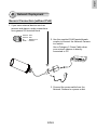
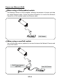
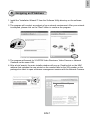
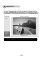
English
Warning Before Installation
Power off the Network Camera as
soon as smoke or unusual odors are
detected.
Refer to your user’s manual for the
operating temperature.
Contact your distributor in the
event of occurrence.
Do not place the Network Camera on
unsteady surfaces.
Do not touch the Network Camera
during a lightning storm.
Do not insert sharp or tiny objects
into the Network Camera.
Do not drop the Network Camera.
EN-1
1
Package Contents
IP8331
Waterproof Connector (3 Holes, for
Backup Use)
Moisture Absorber
Camera Stand
Silica
gel
Power Adapter
RJ45 Female/Female Coupler
Quick Installation Guide
/ Warranty Card
Software CD
510000202G
EN-2
English
2
Physical Description
Front Panel
IR LED
Lens
Light Sensor
Back Panel
Status LED
Reset Button
Connectors
General I/O Terminal Block
Ethernet 10/100 RJ45 Plug
Power Cord Socket (Black)
EN-3
3
Hardware Installation
1. Loose the waterproof connector, and then remove the rubber.
2. Loose the back cover.
3. Tear down the aluminum foil vacuum bag and take out the moisture absorber. Attach
the supplied moisture absorber to the inner side of the Network Camera. (Please
replace the moisture absorber with a new one if you open the back cover after
installation.)
4. Make sure all cable lines are securely connected.
5. Tighten the back cover, rubber and waterproof connector.
6. Secure the Network Camera to the wall/ceiling by the supplied camera stand.
2
6
1
Wall Mount
5
Ceiling Mount
3
Silica
gel
Note
If you want to use your own cable lines, please loose two supplied screws and take out
the power board. Then be careful to make connections as the illustration below.
Power Cord
Upper Side
Terminal Block (from left to right)
1: AC24V (red)
2: AC24V (red)
3: DI (white)
4: GND (black)
Ethernet Cable
Screws
Bottom Side
EN-4
English
4
Network Deployment
General Connection (without PoE)
1. If you have external devices such as
sensors and alarms, make connections
from general I/O terminal block.
AC24V
AC24V
DI
GND
AC24V: 24V+
AC24V: 24VDI
: Digital Input
GND : Ground
2. Use the supplied RJ45 female/female
coupler to connect the Network Camera
to a switch.
Use a Category 5 Cross Cable when
your network camera is directly
connected to PC.
POWER
COLLISION
LINK
1
2
3
4
5
RECEIVE
PARTITION
3. Connect the power cable from the
Network Camera to a power outlet.
EN-5
Power over Ethernet (PoE)
When using a PoE-enabled switch
The Network Camera is PoE-compliant, allowing transmission of power and data
via single Ethernet cable. Follow the below illustration to connect the Network
Camera to a PoE-enabled switch via Ethernet cable.
POWER
COLLISION
1
2
3
4
5
PoE Switch
LINK
RECEIVE
PARTITION
When using a non-PoE switch
Use a PoE power injector (optional) to connect between the Network Camera and
a non-PoE switch.
PoE Power Injector
(optional)
Non-PoE Switch
POWER
EN-6
COLLISION
1
2
3
4
5
LINK
RECEIVE
PARTITION
English
5 Assigning an IP Address
1. Install the "Installation Wizard 2" from the Software Utility directory on the software
CD.
2. The program will conduct an analysis of your network environment. After your network
is analyzed, please click on the "Next" button to continue the program.
IW2
Installation
Wizard 2
3. The program will search for VIVOTEK Video Receivers, Video Servers or Network
Cameras on the same LAN.
4. After a brief search, the main installer window will pop up. Double-click on the MAC
address that matches the one printed on the camera label or the S/N number on the
package box label to open a browser management session with the Network Camera.
Network Camera
Model No: IP8331
MAC:0002D1730202
RoHS
00-02-D1-73-02-02
This device complies with part 15 of the FCC rules. Operation is subject to the following two conditions:
(1)This device may not cause harmful interference, and
(2) this device must accept any interference received, including interference that may cause undesired operation.
Pat. 6,930,709
192.168.5.151
0002D1730202
Made in Taiwan
EN-7
IP8331
6
Ready to Use
1. A browser session with the Network Camera should prompt as shown below.
2. You should be able to see live video from your camera. You may also install the
32-channel recording software from the software CD in a deployment consisting of
multiple cameras. For its installation details, please refer to its related documents.
For further setup, please refer to user’s manual on the software CD.
EN-8


![Cover [IP8331]_Outline](http://vs1.manualzilla.com/store/data/006291669_1-58e4b2a382cb6b9ba21df6b07dfb0c67-150x150.png)
![Cover [PZ81x1,x1W].ai](http://vs1.manualzilla.com/store/data/006040535_1-42ed705d921c196e7271c308c8c31f51-150x150.png)

![Cover [IP8151_8151P]_Outline](http://vs1.manualzilla.com/store/data/006061260_1-bb76daf44ece7d55407dbb3618e33da4-150x150.png)