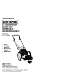
1
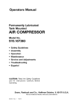
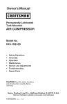
Owner's
Manual
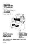
AIR COMPRESSOR
7-gallon
1 HP
Oil Lubricated
Model No. 921.1
CAUTION:
Before using this product,
read this manual and follow
all its Safety Rules and
Operating Instructions.
Sears,
www
Roebuck
sears
5/2C_2005
Pam NO E101434
corn
and Co., Hoffman
•
•
•
•
•
•
Safety Instructions
Installation & Operation
Maintenance & Storage
Troubleshooting Guide
Parts List
EspaSol, p. 10
Estates,
IL 60179
U.S.A.
TABLE OF CONTENTS
Page
Warranty .............................................................
See Below
Safety Symbols ...........................................................
1
Important Safety Instructions & Guidelines .....................................
1
Specifications ............................................................
2
Glossary ................................................................
2
Duty Cycle ..............................................................
2
Parts & Features .........................................................
3
Installation & Assembly ....................................................
4
Operating Procedures .....................................................
5
Maintenance .............................................................
6
Storage
6
................................................................
Troubleshooting Guide .....................................................
7
Exploded View ...........................................................
8
Parts List ...............................................................
9
Espafiol ................................................................
10
ONE YEAR FULL WARRANTY
ON CRAFTSMAN
AIR COMPRESSOR
tf this Craftsman Air Compressor fails due to a defect in materiel or workmanship within one
year from the date of purchase, RETURN ITTO ANY SEARS STORE OR PARTS AND REPAIR
CENTER OR OTHER CRAFTSMAN OUTLET IN THE UNITED STATES FOR FREE REPAIR.
If this Craftsman Air Compressor is used for commercial or rental purposes, this warranty
applies for only g0 days from the date of purchase. This warranty gives you specific legal rights
and you may also have other rights which vary from state to state.
Sears, Roebuck and Co., Dept. 817WA,
Hoffman Estates, IL 60179
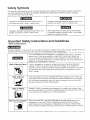
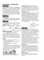
Safety Symbols
The information listed below should be read and understood by the operator. This information is given to protect the
u_er while operating and storing the air compressor.We util_e the symbols below to allow the reader to recognize
imeortant infermation about their safety
Indicates an imminentty hazardous situation which, if
net avoided, will result in death or serious injury.
Indicates a potentially hazardous situation which, if not
avoided, may result in minor or moderate injury.
Indicates a potentially hazardous situation which, if net
avoided, could result in death or serious injury,
When used without the safety alert symbol indicates
a potentialiy hazardous s[tu_L_enwinch, if not avoided,
may result in property damage,
Important
• Save
Safety Instructions
and Guidelines
all instructions
Improper operation or maintenance
of this product could result in serious injury and/or property
understand all of the warnings and safety instructions provided before using this equipment.
damage.
Read and
The air compressor should be operated on a dedicated 15 amp circuit. If the circuit
does not have 15 free amps available, a larger circuit must be used. Always use
more air hose beiore utilizing extension cords. A!l extension cords used must be 12
gauge with a maximum length ol 25 ft. The circuit fuse type must be a time delay Low
voltage could cause damage to the motor.
Risk
of Moving
Parts
If the air compressor is in operation, all guards and covers should be attached or
installed correctly. If any guard or cover has been damaged, do not operate the
equipment until the proper personnel has correctly repaired the equipment. The power
cord should be free ef any moving parts, twisting and!or crimping while in use and
while in storage.
Risk of Burns
There are sudaces on your air compressor that while in operation and thereafter can
cause serious burns if touched. The equipment should be allowed time to cool before
any maintenance is attempted
Items such as the compressor pump and the outlet
tube ere normally hot during and after operation.
Risk of Falling
Operation ot the air compressor should always be in a position that is stable. Never
use the air compressor on a rooftop or elevated position that could allow the unit to fal!
or be tipped over. Use additional air hose for elevated jobs.
i
Risk from Flying Objects
Always wear ANSI Z87.1 approved safety glasses with side shields when the air
compressor is in use. Turn off the air compressor and drain the air tank before
performing any type of maintenance or disassembly of the hoses or fittings. Never
point any nozzle or sprayer toward any part of the body or at other people or animals.
L"np_ant
Safely
Instructions
Risk of Breathing
Risk of
Electrical Shock
Risk of
Explosion
or Fire
Risk of Bursting
& Guidelines
Avoid using the air compressor in confined areas. Always have adequate space
(12 inches) on all sides of the air compressor. Also keep children, pets, and others out
of the area of operation. This air compressor does not provide breathable air for anyone
or any auxiliary breathing device. Spraying matedaTwill always need to be in another
area away from the air compressor to net allow intake air to damage the air compressor
fitter,
Never utilize the air compressor in the rain or wet conditions. Any electrical issues
or repairs should be performed by authorized personnel such as an electrician and
should comply with all national and local electrical codes. The air compressor should
also have the proper three prong groundirig plug, correct voltage, and adequate fuse
protection.
Never operate the compressor near combustible materials, gasoline or solvent vapors.
If spraying flammable materials, locate the air compressor at least 20 feet away from
the spray area. Never operate the air compressor indoors or in a confined area.
Always drain the air compressor tank daily or after each use. If the tank develops a leak,
then reptace the air compressor. Never use the air compressor
after a leak has been
found or try to make any modifications
to the tank. Never modify the air compressor's
factory settings which control the tank pressure or any other function.
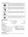
Specifications
Pump ..........................
Oil-lube direct drive
Motor ...........................
1.0 HP (Induction)
Bore .......................................
1.65_
Stroke ......................................
126"
Voltage Single Phase .......................
120 VAC
Minimum Circuit Requirement ................
15 Amps
Air Tank Capacity .........................
Cut-in Pressure .............................
Cut-out Pressure ...........................
SCFM @ 90 PSI................................
Oil Capacity .........................
Oil Type .........................
7 Gallons
95 PSI
125 PSI
24
90 mL or 3 oz.
SAE 30 Non-detergent
Glossary
CFM: Cubic feet per minute.
SCFM: Standard cubic feet per minute; a unit of measure
for air delivery.
PSIG: Pounds per square inch gauge; a unit of measure
for pressure.
ASME: American Society of Mechanical Engineers.
California Code: Unit may comply with California Code
462 (I) (2)/(U) (2).
Cut-In Pressure: The air compressor will automatically
start to refill the tank when the pressure drops
below the prescribed minimum.
Cut-Out Pressure: The point at which the motor stops
when the tank has reached maximum air
pressure,
Code Certification:
Products that bear one or more sf
the following marks: UL, ULc, ETL, CSA, have
been evaluated by OSHA-certified independent
safety laboratories and meet the applicable
Underwriters Laboratories Standards for Safety.
Duty Cycle
This is a 50% duty cycle air compressor. Do not run the air compressor more than 30 minutes of one hour. Doing so
could damage the air compressor.
2
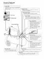
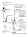
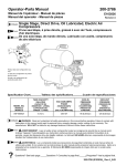
Parts & Features
See figures below for reference.
Provides clean air to the pump and must always
be kept free of debris. Check on a da!ly basis or
Airbefore
Intake each
Filteruse.
J
_!
Regulator
|
k
Gauge
Indicates the outgoing air pressure to the toot and is
controlled by the regulator.
Tank Pressure Gauge
Indicates the reserve
0
--
Oil Fill Cap
_--
Oil Sight Gauge
Pressure
_ressure
"_
air pressure
in the tank.
Switch
This controls the power to the motor and also
the cut-in/cut-cut
pressure settings. This switch
I
serves as the Auto-OnfOff positions for the unit,
J
I
Relief Tube
Pressure
Relief Valve
The pressure relief valve, located on
the side of the pressure switch, is
designed to automatically release
compressed air when the air
compressor reaches cut-out
pressure. The released air should
on}y escape momentarily and the
valve should then close.
J
Outlet
Tube
Tank Safety Valve
Used to allow excess tank pressure
to escape into the.atmosphere.
This
valve should only open when the
tank pressure is above the
maximum rated pressure.
Regulator
The air pressure coming from the air
tank is controlled by the regulator.
To increase the pressure, turn the
knob clockwise and to decrease the
pressure turn the knob
counterclockwise.
!
Used to drain condensation
from the
I Tank
air tanK.
Drain Located
Valve at bottom of tank.
J
Offers a quick release
Quick Connect
air hose.
feature Ior attaching
and removing
When the pump is not in operation, the valve closes to retai
Check
Valve inside the tank. An internal component.
nl
air pressure
3
the
1
Installation
& Assembly
Getting Started-Location of the Air Compressor
The air compressor should always be located in a clean,
dry, and well ventilated environment. The unit should have
at minimum, 12 inches of space on each side. The air intake
filter should be free of any debris or obstructions. Check
the air filter on a daily basis to be sure it is clean and in
working order.
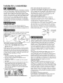
Grounding Instructions
This product must be grounded. In the event of an electrical
short circuit, grounding reduces the dsk of electric shock
by providing an escape route for the electric current.
This product is equipped with a cord having a grounding
wire with an appropriate grounding plug. (See the figure
below.) The piug must be plugged into an outlet that is
property installed and grounded in accordance with all
local codes and ordinances. Check with a qualified
electrician or service personnel if these instructions are
not completely understood or if in doubt as to whether the
toot is properly grounded.
The air compressor shouid be turned off, unplugged from
the power source, the air bled from the tank and the unit
allowed time to cool before any maintenance is performed.
Personal injuries could occur from moving parts, electrical
sources, compressed air or hot surfaces. The quick
connect assembly must be attached before use. Failure
to assemble correctly could result in leaks and possible
injury. If unsure of assembly instructions or you experience
difficulty in the assembly please call our toll free number
for assistance.
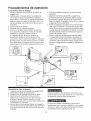
Installing Wheels
The wheels and handle do not provide adeguate clearance,
stability or support for pulling the unit up and down stairs
or steps. The unit must be lifted or pushed up a ramp.
It may be necessary to brace or support one end of the
air compressor when attaching the wheels, because it will
have a tendency to tip.
..
.
r_.-_FS:>
, I
///
"
]*_l-_._I
Grounded
,f.Outlet
Grounding Pin c ... ,
"%
Improper installation of the grounding plug wil! result in a
risk of electric shock. If repair or replacement of the cord
or plug is necessary, do not connect the grounding wire to
either fiat blade terminals. Check with a qualified electrician
or serviceman if the grounding instructions are not
completely understood, or if in doubt as to whether the
product is properly grounded Do not modify the plug
provided; if it will not fit the outlet, have the proper outlet
installed by a qualified electrician.
This product is for use on a circuit having a nominal rating
of 120 volts and is factory-equipped with a specific electric
cord and plug to permit connection to a proper electric
circuit. Make sure that the product is connected to an
outlet having the same configuration as the plug. No
adapter should be used with this product If the product
must be reconnected for use on a different type of electric
circuit, qualified service personnel should make the
reconnection.
Extension Cords
Use only s 3-wire extension cord that has a 3-blade
grounding plug, end a 3-slot receptacle that will accept
the plug on the product. Make sure your extension cord
is in good condition. When using an extension cord, be
sure to use one heavy enough to carry the current your
product will draw. Cords must not exceed 25 feet and
No. 12 AWG size must be used. An undersized cord will
cause a drop in line voltage resulting in toss of power and
overheating.
Break In Procedures
No break in procedure is required by the user. This
product is factory tested to ensure proper operation and
pedormance.
Items Needed For Assembly
1gram or adjustable wrench for shoulder bolt
• 17mm er adiustable wrench for nylon lock nut
Install one shoulder bolt, washer, and one nut for each
wheel using bolt hales provided in the wheel bracket. The
shoulder bolt will install from the outside of the wheel
through the top hole in the wheel bracket. Tighten securely
with the washer and nut positioned on the inside of the wheel
bracket.
Assembly
1. Remove air compressor, manual, air filter assembly,
and accessories from packaging.
2. Remove the plastic plug from the compressor intake
port. (seediagrambelow)
3. Install the filter in the compressor intake port.
(see diagram below)
4. Remove the oil fill cap from the crankcase and fill until
the oil reaches the top of the red dot in the sight glass.
Oil capacity is 3 oz. (seebelow)Use SAE-30 non-detergent
(API CG/CD heavy duty motor oil). Under extreme cold
weather conditions use SAE-t 0 weight oil.
5. Replace the oil cap.
\
[
Estimated AssembtyTime: Approximately5 minutes
4
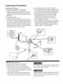
Operating Procedures
Daih/Start-Up Procedures
t. Set the Auto-OnlOff lever to the Off position,
2. Inspect the air compressor, air hose, and any
accessories/toots being used for damage or obstruction.
If any at these mentioned items ere in need of repair/
replacement, contact your local authorized service dealer
before use,
3. Close the drain valve.
4. Check the oil level of the pump.
5, Connect the air hose to the quick connect socket on
the regulator assembly by inserting the quick connect
plug on the air hose into the quick connect socket. The
quick connect socket collar will snap forward and lock
the plug into place providing an air tight sea! between
the socket and plug, To release the air hose push the
collar beck on the quick connect socket.
6. Plug the power cord into the proper receptacle.
7. Turn the Auto-OnfOfl lever to the On-Auto position and
the compressor will start and build air pressure in the
tank to cut-out pressure and then shut off automatically.
8. Adjust the regulator to a PSi setting that is needed for
your application and be sure it is within the safety
standards required to perform the task. If using a
pneumatic tool, the manufacturer should have
recommendations in the manual for that particular
tool on operating PSI settings.
9. The air compressor is now ready for use. The following
inflation and cleaning accessories packaged with this
unit should only be operated at maximum pressure
of 90PSI: blow gun, rubber-tapered nozzle, inflation
needles, adapter, and blow gun adapter.
®
Daily Shut-Down Procedures
1. Set the Auto-On/Off lever to the Off position.
2, Unplug the power cord from the receptacle.
3. Set the outlet pressure to zero on the regulator.
4. Remove any air tools or accessories, When draining
the tank, always use ear and eye protection, Drain the
tank in a suitable location; condensation will be present
in most cases of draining.
5. Open the drain valve allowing air to bleed from the
tank After all of the air has bled from the tank, close
the drain valve to prevent debris buildup in the valve,
When draining the tank, always use ear and eye protection.
Drain the tank in a suitable location; condensation will be
present in most cases of draining.
Water that remains in the tank during storage will corrode
and weaken the air tank which could cause the tank to
rupture. To avoid serious injury, be sure to drain the tank
after each use or daily.
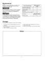
Maintenance
NOTE: Any service procedure not covered in the
maintenance schedule should be performed by
qualified service personnel.
Before each use
or daity
Items to Check./Ohanga
The air compressor should be turned off, unplugged
from the power source, air bted from the tank and
allowed time to cool before any maintenance is
performed.
Chock Tank Safety Valve
X
Overall Unit Visual Check
X
Check Air Filter
X
Drain Tank
X
Check Power Cord for Damage
X
after first 50 hours
Change Oil
To ensure efficient operation and longer life of the
air compressor unit, a routine maintenance schedule
shoutd be followed. The following schedule is geared
toward a consumer whose compressor is used iRa
normal working environment on a daily basis.
Check Oil Level
after every i00 hours
X
Storage
For storing the air compressor, be sure to do the following:
1. Turn the unit off and unplug the power cord from the
receptacle.
2. Remove all air hoses, accessories, and sir tools from
the air compressor.
3. Perform the daily maintenance
schedule.
4 Open the drain valve to bleed all air from the tank.
5. Close the drain valve.
6. Store the air compressor
Notes
in a clean and dry location.
Troubleshooting
_The
Guide
air compressor should be turned off and unplugged from the power source before any maintenance
is performed as welt as the air bled from the tank and the unit allowed time to cool Personal injuries
could occur from moving parts, electrical sources, compressed air, or hot surfaces.
PROBLEM
POSSIBLE CORRECTION
Air leaks at the check valve
A defective check valve results in a constant air leak at the pressure relief valve
when there is pressure in the tank and the compressor is shut off. Drain the tank,
or at the pressure relief vaive,
then remove and clean or replace the check valve.
Air leaks between head and
Be sure of proper torque on head bolts, if leak remains, contact a service technician.
cylinder.
Air leak from safety valve.
Operate the safety valve manually by pulling on the ring. If the valve continues to
leak when in the closed position, it should be replaced.
Pressure reading on the
If there is an excessive amount of pressure drop when the accessory is used,
regulated pressure gauge
replace the regulator.
drops when an accessory is
used.
NOTE:
Adjust the regulated pressure under flow conditions (while accessory is being used),
It is normal for the gauge to show minimal pressure loss during initial use of the
tool.
Excessive
tank pressure.
Move the Auto-On/Off
lever to the Off position.
from the power source and contact
Motor will not start.
a service
It the unit doesn't
Make sure power cord is plugged in and the switch is on. Inspect for the proper size
fuse in your circuit box. If the fuse was tripped,
repeated
Excessive
moisture
discharge
air.
shut off, unplug it
technician.
in the
tripping
reset it and restart the unit. If
occurs, replace the check valve or contact
a service technician
Remove the water in the tank by draining after each use. High humidity
environments
will cause excessive
condensation.
Utilize water filters on your air
line.
NOTE:
Water condensation is not caused by compressor malfunction. Be sure the
compressor's air output is greater than your tool'e air consumption rate.
Air leaks from the tank body
Never ddfl into, weld or otherwise
or tank welds.
rupture or explode. Compressor
compressor.
modify the air tank or it will weaken. The tank can
cannot be repaired.
Discontinue
use of the air
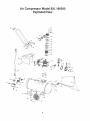
Air Compressor Model 921,166390
Exploded View
2
22
Air Compressor Model 921.166390
Parts List
/
I
PARTDSSCRIP_I_
Screw, socket head, M6 x 1.0 x 34)ram
Wash_r,Lock,6rnm
O_ndar head
1
2
E1002271
3
4
!E100809
F'_r',9,90 De_,3/8' NPT X 3/8" Compression
5
1 Housinq.Air intakeRltar,Die Cast
EID0435!
1 Elek'_Br_Air Fiitar
6
7
E101178
1 Om,erTAJrFilter
B
2 Gasket, head
9
Valve plate
10
Valve,Reed
11
2 GaskeL,Vatve platte
12
2 Gasket_CylindehUpper
13 5101113
OyUndorJD 42ram X H 85rnm
14
Screw,SHOS,M6 X 1.0 X 20 mm
15
Gasket,Cylinder ,Lower
!6
Motor
17
Nut, M6 X 1.0
!8
3 E_nt_c
I
Ig
3 PistonAssemb_
20
3 Pang,Scraper
21
3 Pang,Compression
22
2,6 E_affle,Rubber
23
E139357
6 Oil Fill Cap
24
6 O-rtn_ 2ram X 13.5 mm ID
25
6 Cover,CranP.case
26
:_crew,Hex F-3angeHead,M5 X 0.8 X 15 mm
27
4,6 iSea_,Oi!Si.qht Gauge
25
4,6 Gau_e,Oil Sight
2g
SCr_w,SNOSrM8X 1_25X 16ram
3O
Washer.Lock 8mm
31
=WashorrFletrSrrlm
32
iNuLHox,MB X 1.25
33
8 \lut,Compression,3/8"
34
5 :errul_,Comp,-_s_)st 3_"
35
8 tube,Outlet
36
E100898
ICh_k Valve
37
7 IF_rrule,Comprgssion, 1/4"
38
7 NutiCompresslon, ll4"
39
7 Pressure Re of Tube
QT"
8
1
I
I
I
I
1
2
2
1
1
1
5
I
I
1
1
I
I
2
1
t
1
1
8
1
1
4
B
10
5
2
2
1
I
2
2
1
I
PA_T_ /K_ I
PARTDESCRIPTION
QTY,
I
I
43
41
42
I
I
Tank
Nut,Max,M10 X 1.25
Wa$her,Fl_ 1Dram
I
2
2
_Whe_l,P..edHub
IBolt,Shoulder,M10X125X
45ram
IBOK.He_,M8X 1.25 X 3_ram
43
44
45
45
E101353
E10149
Ilsolator,Rubber
2
2
I
1
47
45
49
50
E10_81
E1013401
I
E1009571
Drain Valve
,
Power Cord, le23 X 6,ST
Nipple, 114"NPT X 13"
pressure switch
1
1
I
1
51
52
E1003941
E100Z0S !
',Valve,Safety
IPr_sur_Gau_te,2",200PSI
1
1
IReduletorlNippie'
1!4" NPT X 1=
11
IPTessure Gauge,1 _'_O0 PS
IOouplarrQuiok-connoct
Isc_,,,4Hex Rondo Hsad.M5 X 0 5 X 10ram
IShroud,Plas_c
]BolLH=..z_M8X 1.25 X 25ram
IHandle
IRivet Nut, SerratedpM8 X 1.25
IHandgdp
IManual
I
I
8
1
4
1
4
1
1
I
E1002401
5453 E100059
55 E!00Dg3
56
I
57
I
58 E1011371
5£
I
80
I 5
61
I
62 E1014g0
5
k_ oh=w,E!01433
I
I
I Not=:Only :omponcttswitha listsd paW_ numberare available.Desoffptb_sare
Ipr°vided forre_renc_ only. The _t # columndenotes_qecompons,-_being offered
as part ofa kit.
I_d No. Par_ No. I Description; Referen_
Numbers
1
2
3
4
5
E101179 Ilntake fi_r Id_ 5,6,7
EI0Og59 3_sket kit; B, 11, 12, 15, 22
Et03251 P_ton kit;,15, 1g, 20,21
E10D055 S_ht _auoe k_, 27, 28
E!01492 NandieKit;
BO,62
6
7
8
E101332 Crank_-"asecover k3_ 22, 23, 24, 25, 27, 28
E101430 Pressure re ett_be Idt; 37,38,39
E101429 IOuffet tube kit: 33, 34, 35
I
Contenido
P_gina
Garant_a
esta pagina
Sfmbolos de seguridad ....................................................
11
Instrucciones y pautas de seguridad importantes ................................
11
Especificaciones ..........................................................
12
Glosario ................................................................
12
Cicio de trabajo ..........................................................
12
Partes y caracter[sticas ....................................................
13
Instalaci6n y ensamblaje ...................................................
14
Procedimientos de operaci6n ................................................
15
Manter_imiento ...........................................................
16
Almacenamiento ..........................................................
16
DiagnSstico y oorrecci6n de fallas ............................................
17
Lista de partes .......................................................
GARANTIA
DE
UN
AI_O PARA
EL
COMPRESOR
9
DE AIRE
CRAFTSMAN
Si este compresor de aire Craftsman !lega a fallar debido a un defecto de manufactura o de
materiales en un plaza de un aSo, desde la fecha de compra, DEVUELVALQ A LATIENDA
U A OTRO CENTRO CRAFTSMAN
O CENTRO DE SERViCIOY
PARTES SEARS EN LOS
ESTADOS UNIDOS MAS CERCANO para que sea reparado sin ningdn cargo.
Si este compresor de aire Craftsman se usa con fines comerciales o de renta, esta garantra
Onicamente se apliea por 90 dfas a partir de la fecha de compra, Esta garant[a le da derechos
legaies aspec[ficos; adem&s, es posible que usted tenga otros derechos, los cuales var[an
seg6n el estado.
Sears, Roebuck and Co., Dept. 817WA,
Hoffman Estates, IL 60179
10
Sfmbolos comunes de seguridad
E! operador debe leer y entander la informaciPn descrita a continuaeiPn. Esta informaciPn se ofrese pars proteger al
usuario al oparar y almacenar el eompresor de aire. Los s[mbolos siguientes son los que se utilizan para indicar sl lector
informaciPn que es importante pars su seguridad
Ir_dica una situaciPn de riesgo inminente que, al no
protegerse, proveoara tesiones graves oia muerte.
Indies una situaoiPnpotencialmentepeligrosaqua, de no
evitarse,podria provocarlesiones menoreso moderadas.
Indies una situaciPn potenclalmeme p_hgrosa qua, al no
protegerse, podria provocar lesiones graves o la muerte.
Cuandono aparezca sin ei simbolo de alerts de saguridad,
esto quiere decir que hay una situaci6n potenciatrnente
peiigrosaqua, al no protegerse,podria causer defies
materiales.
lnstrucciones
y pautas de seguridad importantes
• Guarcle redes las instru¢ciones
•
La operaeiPn y el mantenimiento
inadeeuados de este products pueden provecar }esionas graves y da_es materiales.
Antes de utilizer este equips, lea y entienda los advertencias e instrucciones de segurided aqu[ eontenidas.
El compresorde aJrese debe operar desde un circuits especial de 15 amperios.
Si el circuits no disDenede una capacidad de 15 amperios,sa debe user un circuits de mayor
capacidad.Si as neceeario,antes de amplest una e×tensiPnelPctrica,afiada uha manguerede
aire m&slarge. Las extensiones electricasdeben set de calibre 12 y tenor una Iongitudm_<ima
de 7,6 metros.El fusible del circuits debe set de accion
retardada:Un voltaje demesiado bajo puede daPar el motor.
Riesgo
per partes
movimiento
Riesgo
de quernaduras
Riesgo
de cafda
N
Riesgo de lanzamiento
de objetos
en
AI operar el compresor, redes los protectores y cubiertas deben ester fijades e
instslados correctsmente. Si alguno de los protectores o cubiertas est_ daPado,
no spare el equips haste qua personal eafificado repare el problems. El cable de
eorriente debe mantenerse elejado de Iss partes mPviles de1 equips y no debe
torcerse ni prensarse durente su empleo, ni al slmacenarse.
En su compresor hay superficies que, a! ser tocadas durante y despuPs de su
operaciPn, puederl causer quemaduras graves. Antes de darle mantenimiento al
equips, se debe dejar enfriar. Per Io normal, dursnte y despu_s de su operaciPn,
sierras partes come la bombs del compresor y el tubs de salida estar&n calientes.
El compresor siempre debeser operado en una posiciPn estable Nunca utflice el
compresor sobre un tachs oen una posiciPn eleveda ya qua podrfa caero
volcarse. A! trabajar en posioiones elevadas, utilice una manguera de dire m_s large
A! emplear el compresor, siempre utilice anteojos de seguridad con protectores
laterales qua cumplan con la norma ANSI Z87.1. Antes de Ilevar a cabs cuelquier
clase de mantenimierlto y antes de desoonectar las mangueras y }os acepladores,
apague el eompresor y drene el tanque de sire. Nunca apunte la boquil[a o el rociador
hacia ninguna parte de eu cuerpo, ni 61 de otros seres
I
11
_nstrucciones
y pautas
de seguridad
importantes
Evite utilizer e! compreeor de aire en Areas enoerredas. Siempre tangs un espacio
libra adecuado (30 am.) en redes los Iados del compresor. Tambi6n mantenga fuera
dei Area de eperaci6n a iae mascotas, nifios y otras personas. Este oompresor de aire
no proves aire que pueda ser respirado ni empleade con un dispositivo reapiratorio
auxiliar. El material de rociade siempre deberA estar en otra zone, alejado de!
compreeor de sire, pare evitar que el airs aepirado dafie al filtro det oompreser.
Riesg9 pa.raLa
resplraclon
Riesgo de
descargas
e|4ctricas
Nunca L_tilice el compresor de airs bajo Iluvia oen lugares mojados. Los problemas
ei6ctricos deben ser reparados per personal autorizado, tel come saris un electrioista,
y deben oumplir con las hermes elActrioas nacionales y locales. El oompresor tambi_n
debe lener la eiavija apropiada de tree terminales para haoer tierra y center con
un suministro electrico que sea del voltaje corrects y con un fusible de proteaoi6n
adecuado.
Riesgo de
explosi6n y fuego
Nunoa opera el compresor ceroa de materiales combustibles, gasoline ni vapores de
solventes. SiestA rociando matariales infiamables, oe!eque el oompresor a una
distancia de cuando manes 6 metros del Area de rooiado. Nunca spare el oompresor
de airs en interiores o en lugares oerrados.
Riesgo de estallido
Drene e! compresor diariamente o despu6s de cads utiiizaoi6n. $i el tanque tiene una
fuga, reemplace el compresor. Nunoa utilice el oompresor si se ha detectado una fuga,
ni trate de modificar el tenque. Nunoa modifique los ajustes de fabrics del eempreser
que oontrolan [a presi6n de[ tanque y demAs funeiones.
Especificaciones
Bombs
............................
directs,
Motor
De impulsi6n
lubrioada con aceite
...........................
Di&metro ...................................
Carrera ...................................
Volteie monof_sico
Capacidad minima
.........................
de! circuits ...................
1.0 HP (InducoiSn)
42 mm
t32 mm
120 VAC
15 A
Capacidad del tanque de airs ...............
26.5 Iitros
Presi6n de arranque ...............
655.0 KPa / 95 PSI
Presibn de parada ................
861.8 KPa / 125 PSI
PiesctJbicosperminute(SCRvl)a 90 LPPC.....................
2.4
Oapecidad det aceite ................
90 mlo 3 enzes.
Tips de aceite ..................
SAE 30 - no detergents
Glosario
CFM:
Preai6n
de arranque:
El compresor arranoa
autom_.tioamente cuando la presi6n baja a manes
de! minimo prescfito
Preai6n de parada:
El motor se pare cuando el tanque
alcance la presi6n m_.xima de ape.
Certificacibn
de c6digo: Los productos qua tienen
alguna overiaa de lea siguJentes marcas han side
evaluados per laboratories de seguridad
independientes
certificados per OSHA, y cumplen
con las normas de seguridad de Underwriters
Laboratories:
UL, , ETL, CSA.
Pies cObioos per minute.
SCFM: Pies cL]bicos est_.ndar per minute; unidad de
medici6n de suministro del sire.
PSIG: Libras per pulgada ouadrada sobre Is presi6n
etmosf6rica; unidad de medioi6n de presi6n.
ASME: Sociedad estadounidense de ingenieros mec&nicos.
CSdigo de California: La unidad puede cumplir con el
c6digo de California 462 ([) (2)/(M) (2).
Ciclo de trabajo
Este compresor
tiene un oiclo de trabajo de 50%. Nunoa opera el oompresor
Ya que al haserlo,
podn'a daRario.
12
per m_s de 30 minutes cads hera.
Partes y caracterfsticas
Come referencia,
yea tas figuras abajo.
f
Filtro del aire
Suministra aire iimpio a la bomba. Siempre
I
debe consen_arlo limpio
antes de oada use.
Revfeelo
diari_mente
I
Indies la presi6n de salida del aire que entra en ia
Man6rnetro
herramienta,de lapresi6n
oual qua
deessalida
controlada per el regulador.
J
ManSmetro
de prest&n
del tanque
Indic_ la presiSn de la reserva de aire del tanque,
_Tap6n
de Itenado
de aceite
"]
J
Interrupter de presi6n
Controla el Suministro eiectrico en el motor y
tambi6n los _justes de presiSn de arranque y
preeiSn de parada. Este interrupter sirve come
posiciSn de autoencendido y apagade (Auto-Or',!
Of_ de }a unidad.
Visor de aceite
r
V4tvula de alivio de presiSn
Esta v&lvula, que se encuentra en el
oostado deL interrupter de presiSn,
esta diseRada para liberar aire
comprimido de m_nera autom_tica
cuaedo el compresor Ilegue a ia
presi6n de pareda, El aire s6}o
deber_ esoapar durante un instante,
cerrandose la v_lvula se cerrara, en
Tube de _lrvio de presiSn
seguida.
Tube de
satida
©
'_lvuia de seguridad
ciel tanque
Permite que el exceso de presi6n en
el tanque escape hacia el medic
ambiente. Esta v_lvula s61o se
abrir_ cuando la presiSn en el
tanque este per encima de la
presiSn m_xima nominal del modelo. J
ulador
La presi6n del aire que sale de1
tanque es controlade per el
regulader. Para aumentar ia presi6r
gire ia perilla en direceiSn de las
manecillas; para disminuifla, gire la
perilla en direcci6n contraria alas
manecillas.
..
r
V_lvula de drenaje
Sirve para drenar {a condensaci6n
acumulada en el fondo de! tanque.
$e encuentra en ta parte inferior de[
tanque.
Conector
de acoplamiento
r_pido
Permite conectar y desconectar
del aire.
V_,lvula de retenci6n
"_
r#,pidamente }a manguer
"_
Cuando la bomba no est& en operaeiSn, esta v&lvuia se cierra para
retener la presibn de aire dentro del Lanque, Es un componente interne _
13
lnstalaci6n
y ensamblaje
Primer paso: Ubieaci6n
del compreeor
de ai_
El corn.preset de sire siempre dsbe ester en un medic
Antes de reaiizar cuaiquier
de sire, se to debe apagar
inetaleci6n y ensamblaje a] com.presor
y desoonecta.r del generador, adem._.e
am.biante
tirnpio, seco y bien ventilado. La unidad debe tenar per Is manes
30 cm de espacio libre en cads lade. La tom.a de! fiitro de sire
de purger eT airs del tanque y darle suficiente tlem.po pare
enfriarse. E×iste el riesgo de qua las partes m6vile& la fuente
debe ester limpia y sin ningQn tips de obstrucciones.
Per favor
revise diarlem.ente el filtrn de sire pare comprobar
que est_
et6ctrica,
limpie yen corrects eetado de funeionam.ier_to.
lnstrucaiohee
de conezi6n
a tierra
el airs com.primido
tssiones. El ensemble
de user el compresor,
y las superficies
saiientes
provoquen
del regulador dabs ester instalado antes
Un ensamblaje inedesuado
puede ser
ca,usa de fugas y posiblemente
de entender les instrucciones
pare Ilevar a cabs el armada,
toss1 de sere'isis
de leeiones,
Este products
Si no est& seguro
cortoeireuito,
de ensam.biajs o tiene difisultad
per favor Ilarne a su departam`ento
se debe
conectar
la oonexi6n
a tisrre.
En case
de
reduce
e! riesgo
de
a tierra
deeoargae
electricas
al ofrecer una ruts de escape
corriente
el_,ctrica. Este products
cuenta con
pare la
un cable qua tiene un alem.bre de tierra y una clavija
con terminal de tierra (ver [a figure, a oontinuaci6n).
La clavije
debe
tierra
Instalaci6n de les ruedae
Les ruedas y el aaa no proveen eufieiente espacio libre,
estabilidad ni soporte pare subir y bajar ta unidad per escaleras
o sessions& La unidad debe ser levantada o ernpujada per una
ram.pa.
enchufarse
en un tomaoorriente
instalado y puesto
seg_n les norm, as locales. Hable con un electficista
agents
de servlcio
eeiificado
si no entiende
estae inetruccionee,
o s[ tiene
a tierra de le herram.ienta.
dudes
a
o
oornpletamente
eobre
Is corrects
C'levija
pueste
Tornacorrientes
GOR _oJ3exi613
AT co!scar lee ruedas, puede ear necesado
/
/
o soporter uno de tos extrernos del compresor de airs, ya qua
tencler_ a volcerse.
Terminal de
tletTa
Una cone×i6n
'''
•
•
neceeariae
pare el pemo con tope
pare [a tuerca de
seguridad de nylon
Instale un pemo con tope, una arandela
rueda,
vali6ndese
de los orificios
y una tuerca
pare pemos
una de_carga
eonexiSn a tierra, o si tiene dudes sobre la corrects
a tierra de la herr'am.ienta, hable cor_ un electricista
que est#,n en los
la ruede. Coloque la arendela y la tuerca an el lads interior
soporte de la rueda y apri_tela con firm.eza.
de
puesta
o agente
de servicio calificadc. No modifique
la clavija que viens con el
equips; si no puede enchufarie en el tom.acorriente,
Ilarne a
en cada
soportes de las ruedes. El pemo con tope ee instala deeds el
exterior de Is rued& a traves del erificio superior del soporte de
Eneamblaje
!. Rem.ueva el corn.preset
puede provocar
El alambre de tierra es el de color verde, con o sin franjas
em.erillas. Si no entiende eom.pletamente
las inetrueoiones
pare at eneamblaje
Uave de 19m.m. o liave ajustabte
Llave de 17ram o Ilave ajustable
a tierra inadecuada
_'-
el_ctrica. Si neceeita reperar o cam.bier el cable o la alavija, no
conecte el atambre de tierra a ninguna de las term.inaLes planes•
aqui
Herrarnientas
a
tierra
que tenga que epuntaJar
del
un eieetricista
adecuado.
calfficado
pare que le instale el tornacorfiente
Eete products
eeta diseSado
pare trabajar
an un eircuito
con
un voltaje nomine; de 120 voltiee y esta equipado con ur7
cable y clavija que permften su oone×i6n eun circuits el_ctrioo
apropiado. AsegLirese de qua el products
tornacorfiente
con le miema cenfiguraci6n
eet_ conectado
aun
que la clavija. No se
de airs y eccesones
de ta em.paquetadurs.
2. Remueva el tapSn de plastics de ta salida de sire del
debe user un adaptador con este equips
equips aun circuits el_ctdco de diferente
Si se debe conectar el
tips, cor_siga la eyuda
cornpreser. (vet abajo)
3. Instalar el fiitro dentro de la entrada
de personal calificado
Gables de ex'tensi6,n
de sire, m.anual,
ensamblaje
del filtro
de airs del compreson
(ver abejo)
S61o utilice
4. Remueva la tapa de} tanque
II_,ne!o haste Begat el punts
de eceite del c_rter del motor y
rojo maraado en el viddo
motoree
de gran capacidad).
un cable de extensi6n
estimado
En case de fries extremes utiliee
de enaamblaje:
de tres atam.bres con una
de
qua su cable de extenei6n est_ an buenas condicienes.
Si utilize
un cable de extensi6n, cornpruebe
que sea de la capacidad de
corriente
qua requiere
su equips.
Las extensiones
no deben
ser de m&s de 25 pies (7.6 m) de largo y deben tenet cable de
calibre 12 AWG. Un cable m_s delgado provocara una cards en
de aceite.
el veltaje de lines,
sobrecalentamiento.
Tiempo
minutes
le reoonexibn.
clavija con extensi6n a tierra de tres terminales
qua pueda
enchufarse en un tornacordente
de tres orificios Asegt3rese
transparente.
La aapecidad
de aceite es 3oz (ver abajo).
Utiliee SAE-30 sin detergente
(API CG/CD aceite pare
aeeite pesado SAE-10.
5. Coteque nuevamente la tape del tanque
pare realizer
Io que provocar[a
una p_rdida
de poteneia
Proceclirniento
initial de preparaei6n
No se requiere un procedimiento
initial de preperaci6n
Este products ha side probado en lafe, brica para
asegurer su operaei6n y dasempeSo adecuades
Aproximadarnente
14
y
Procedimientos
de operaci6n
Procedimiento
diario de arranque
1. Penga el interrupter Auto-On/Often
la posici6n de
apagado (On.
2. Ver_ique qua el compresor del aire, ia manguera de
airey todos bs accesorios/harramientas
utilizados, no
tengan daSos ni ebstrucci6n. Si algunas de las piezas
descritas requieren raparaci6n/reampiazo,
liarr_e a su
tienda autorizada local de servicio, antes de user el
oompresor.
3. Cierre }a v_lvula de drenaje.
4. Revise el nivel de aeeite de ;a bomba.
5. Enchufe la manguera del aire dentro de! conector
de aeoplamiento r_.pido de la unidad del reguladar,
insertando la clavija de aonexi6n rApida en
la manguera de1 aire, dentro del coneetor de
aeeptamienta r_.pida. El eollarfn del conecter de
acoplamiento
r_.pido saltar_ haeia adelante, aujetando
la clavija y har_. una junta entre el conector y la clavija.
Para deseoneotar la manguera del aire, empuje hacia
atr#,s el collarfn del eonecter de aooplamiento r_.pido.
6, Enahufe el cable de corriente
en un tomacorriente
aprepiada.
7. Mueva ei interrupter Auto-OniOffa
la posiei6n de
eneendido (Auto-On); e! sempresor deber_ arranaar,
acumulando ta presi6n del aire an el tanque hasta
Ilegar a la preai6n de apagado, memento en el cual se
apagar_ de manera autom_.tiaa.
8. Ajuste el regutador a la presi6n de sire recomendada
(PSI) pars su aplicaci6n, oeraier&ndose de qua est_
dentro de tas normas de seguridad para Ilevar a cabo
la tarea. Para las herramientas
neuma.tiaas, el manual
del fabrieante debe tenet recomendacienes
sabre su
presi6n de operaei6n (PSI).
g. Ahora el eompresor del aire asta listo para ser usado.
Los siguientes accesorios de infiado y de limpiaza, los
cuales vienen con esta unidad, s6io se deben operar a
una presi6n m&xima de 90 PSI: sopiete, bequilla c6nica
de caucho, agujas para infiar, adaptador y adaptador de
sopiete.
/
®
¶'_]r
Procedimiento
diario de apagedo
1. Pangs el interrupter en la pasiei6n de apagado (Off).
2. Desconecte el cable del temacorriente.
3. Pangs en aero el reguiader de presi6n de salida.
4, Desconecte las herramientas y los accesorics,
AI drenar el tanque utilice proteoci6n para aides y ojos
Drene el tanque en un lugar apropiado; en la mayer[a de
las ocasiones al drenar saldr& condensaci6n
Siempre use pretecci6n para les aides y los ojos
al drenar el tarlque. Drene el tanque en un lugar
adecuado; en casi redes los cases habr_, presencia de
condensaci6n
en el drenaje.
5. Abra }a v_.tvula de drenaje permftiendo qua escape et
aire del tanque. Cuando hays salido del tanque todo el
aire, cierre la v_.lvula de drenaje pars evitar qua entre
suciedad.
Si no drena el tanque al almacenarlo, en su interior
quedar& agua que Io corroer_ y debilitar&, Io eual puede
provocar su ruptura. Pars evitar lesiones graves, drene el
tanque diariamente a despu_s de eada use.
15
Mantenimiento
NOTA: Cualquier precedimiento de servicio que no est_
cubierto en el programa de mantenimiento que sigue
debera ser efectuado el persona! de servicio cs.lificado.
Antes de dar mantenimiento
al equipo, se debe apagar
y desconectar del tomacorriente,
as[ come .purger el eire
del tanque y permitir que la unidad se enfr[e.
A fin de esegurar una operaci6n eficiente y usa large
vida del compresor, debe seguir un programa de
mentenimiento de rutina. El siguiente programa de
mantenimiento est'. enfecado ai oor_sumidor cuyo
compresor es usado en un medio ambiente normal y
diariemente.
Asuntos pare verificsrl
cambiar
Antes de cads use
o diariamente
Reviser la v_vula de seguridad del
tanque
X
Reviser visuatmehte el aspecto
general de la unidad
X
Reviser el filtro de sire
X
Drenar el tenque
X
Verificar que el cable eleetrico
no est_ daSado
X
Cambier e! aceite
Vefificar el nivel del aceite
Despuesde l_s primeras
50 horas
Deepu&sde cada 100
hores
Almacenamiento
Pare atmacenar el eompresor, asegQrese de hacer io siguiente:
1, Apague la unidad y deseonecte el cable el_ctrico de[
tomacorriente.
2. Quite del oompreeor ias mangueras, accesorios y
herremientas de &ire
4. Abra la v&lvuia de drenaje pare drenar el eire del
tanque,
5. Cierre la v_lvula de drenaje.
6. Guarde el compresor en un lugar limpio y seco.
3, Lleve a cabo el programa de mantenimiento de rutina.
NOTA
16
Diagn6stico
_Antes
y correcci6n
de fallas
de Itevare cabo cJalquier correcciSnde problemas o tares, e! compresorde aJrese debe apagar
y desconeotardel tomacorriente.Purgue el aire del tanque y permite que la unidad se enfffe. Las
partes en movimiente,las fuentes el$ctricas,el sire comprimido y tas superficies calientes pueden
provocar lesiones.
PROBLEMA
POSlBLE CORRECCION
Fuga de sire en le v#Jvuta de
Una v_.tvula de retenciSn defectuoea provoca una fuga de sire constante en la
retenei6n o en la v_.lvula de
vbJvula de alivio cuando est& apagedo el compresor teniendo presi6n de aire.
alivie.
Drene el tanque y quite y limpie o cambie la v_.lvula de retenci6n.
Fugas de aire entre la oabeza
Compruebe el apriete de los pernoe de ta cabeza. Si contin'3a la fuga, llame aun
y el oilindro,
t@cnico de servicio.
Fuga de sire an ia v_lvula
Opere manualmente la v_lvule de segurided tirando del anillo. Si el tanque eentinL_a
de seguridad,
teniendo una fuga estando la v&ivula en posici6n oerrada, @stadeber_ eer cambiada.
La presi6n indioada en el
Sial user un accesorio hay una ca[de excesiva de presi6n, cambie el regulador.
man6metro de presi6n
regulade aae al user un
aoeesorio.
Ajuste la presi6n regulada bejo eondieiones
accesorio).
Es normal que el man6metro
de flujo (mientras
se utilize un
indique una cards de presi6n
mfnima
al comenzar
e utilizer la herramienta.
Presi6n exoesiva
Apague
el interrupter
en el tanque.
tomacorriente
El motor no arranca.
Oompruebe que el cable de corriente est8 enehufado y que el interrupter este
encendido. Compruebe qua el fusible de la ca)a de circuitos sea de la capacidad
adecuada. Si se ha disparado, restabl6zcato y vuelva a arranoar la unided. Si el
de encendido.
y eomunfquese
Sila
unidad no se apaga, descon_ctela
del
con un t_cnice de servieio.
fusible ee dispera con frecuencia llame aun t_cnico de servicio.
Humedad
exceeiva en el
Saque el ague del tanque dren_ndoto
medios
aire de salida.
ambientes
de site humedad
despu6s
de cada vez que se use. En los
habr_ un exceso de condensaei6n;
instale
filtros de ague en su lines de sire
La conderlsaci6n
no es provocade
salide de sire del oompresor
Fugas de aire an el euerpo
Nunca taladre, suelde o modifique
o la soldadura
El tanque podr[a romperse
del tanque.
utilice el compresor
de eire.
17
per una falls en el compresor.
sea mayor que el consume
de ninguna
o explotar
Oompruebe
que le
de sire de su herramienta.
manera el tanque,
pues se debilitara.
El tanque no puede ser reparado. Ye no
Your Home
For repair - in your home - of all major brand appfiances,
lawn and garden equipment, or heating and cooling systems,
no matter who made it, no matter who sold it!
For the replacement
parts, accessories
and
owner's manuals that you need to do-it-yourself.
For Sears professional installation of home appliances
and items like garage door openers and water heaters.
1-800-4-MY-HOME®
(1-800-469-4663)
Cal! anytime, day or night (U.S.A. and Canada)
www.sears.com
www.sears .ca
_;,_
Our Home
__
For repair of carry-in items like vacuums, lawn equipment,
and electronics, call or go on-line for the location of your nearest
Sears Parts & Repair Center.
1-800-488-1222
Call anytime, day or night (U.S.A. only)
WWW.saars._om
To purchase a protection
or maintenance agreement (Canada)
1-800-827-6655
(U.S.A.)
Para pedir servicio de reparaciSn
a domicilio, y para ordenar piezas:
agreement (U.S.A.)
on a product serviced by Sears:
1-800-361-6665
Au Canada pour service en fran_ai_:
1-888-SU-HOGAR _
(1-888-784-6427)
.......
_'
:
dt<.
]
!_:
i
; i
2
(Canada)
1-800-LE-FOYER '_c
(1-800-553-6937)
}
www,searm ca
Sears
....
@ Registered Trad_marW TM TrademarW _S_'vice Mark of gears, Roebuck and Co
Marca _÷gislradaJ _ Marca de F_brica! _M_r_a d_ Sg_vi_io _e Sea.r$, F_OebLJckand C,0
M_,Marqu_ d_ _rnmera_'_Mar_u_
d=-'pos_ de Sea_ R_ebuck and Co
Sear_ Brar_ds, LLC