1
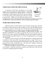
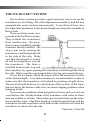
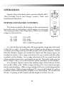
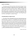
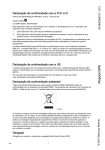
FL-8SLT Operation Manual
CONTENTS
General Description
Specifications
Unit Installation
Power Connection
Transducer Installation
Operation
Typical Indications
Maintenance
Operational Questions & Answers
Transducer Beam Angle Chart
Trouble Shooting Chart
Accessories and Other Products
Transducers
Service and Support
2
3
4
4
5-8
9 - 10
11 - 14
15
16 - 20
21
22
23 - 25
26 - 27
28
Founded in 1960, Vexilar, Inc. has a long history of bringing revolutionary technology to the
sport fishing industry. Just some of the Vexilar
firsts include: the first liquid crystal display, the
first fish alarm, the first three color display, and
the first CRT and straight line paper graphs, for
the sport fisherman. Now, with the FL-8SLT, we bring you the first true
interference Rejection unit. Again, Vexilar leads, while the others follow.
1
GENERAL DESCRIPTION
The FL-8SLT is a compact
and
lightweight
depth
sounder designed for serious
anglers. Besides indicating
depth, the unit also shows
changes in bottom content and
conditions. It can also discriminate between large
underwater targets, such as
fish, and smaller targets such
as bait fish and plankton.
The unit transmits bursts
of high frequency pulses,
which are converted from
electrical to mechanical energy by the transducer. These "sound" pulses
radiate from the transducer downward and are reflected back up to the
transducer where the energy is converted back to electrical signals. The
FL-8SLT then processes these signals and displays them.
The circular display is accomplished by attaching an LED (Light
Emitting Diode) to a wheel, which is then spun at a high speed in the
clockwise direction. This allows for an extremely high speed update.
The bottom, as well as other targets, can be displayed as red, orange, or
green to indicate strong, medium and weak signals respectively. The FL8SLT also has patented Interference Rejection (IR) Technology. This lets
the user "filter out" unwanted interference from another nearby depth
sounder. With two models available, deep and shallow, and a wide variety of accessories to choose from, the Vexilar FL-8SLT is second to none.
2
SPECIFICATIONS
Operating Voltage:
Current Draw:
Power Output:
Frequency:
Resolution:
Target Separation:
Display Colors:
Dimensions:
Weight:
10.5 - 15 Volts (12 Volts Nominal)
200mA
400 Watts (Peak to Peak)
200 kHz
525 Segments
2.65" Min.
3 - Red, Orange, and Green
4.4"H x 6"W x 2.5"D
1.1 Lbs.
Depth Scales:
0-20', 0-30', 0-40', 0-60', 0-80', and 0-120' - Shallow Model
Or
0-20', 0-30', 0-40', 0-60', 0-80', and 0-240' - Deep Model
Beam Angle:
If your transducer is not marked, you can determine the beam angle
by the dimensions of the transducer face. Measure the shortest distance
across the face of the transducer. 19˚ transducers measure about 1 1/2”.
9º and dual beam transducers will be about 2 1/2” across the face.
3
INSTALLATION
To make the FL-8SLT work, you must provide the unit with power
and mount the transducer in an appropriate location.
UNIT INSTALLATION
Find a convenient place to
mount the unit. This may include
a boat seat, deck, dash, or a
portable case. Make sure that there
is plenty of room for the unit to tilt
and/or swivel freely without the
cables binding behind the unit.
Once you have found a spot,
remove the unit from the gimbal
bracket. Securely attach the bracket to the mounting surface.
POWER CONNECTION
Plug the flat 3 pin connector into the back of the unit. Find the closest source of 12 volts and run the cord to it. Keep the cord away from
sharp metal edges and avoid tight places where the cord may get crushed.
Connect the red wire to positive and the black wire to negative or ground.
If the cord provided is not long enough, more can be added. Use 18 gauge
wire minimum. It is recommended that a 1 amp in-line fuse be placed
in the positive line as close to the power source as possible to protect
against any shorts in the wiring.
4
TRANSDUCER INSTALLATION
There are three basic types of transducers to consider: High Speed,
Puck Style, and the Ice-Ducer System.
HIGH SPEED TRANSDUCERS
High Speed transducers are
designed to be mounted on the transom
of a boat. The wedged shape will cut
the water and give a clear depth reading at any boat speed. Locate a spot
similar to the one in figure E. Keep in
mind that you need clear water flow
across the face of the transducer to
insure a clear reading at all speeds. Stay
away from rivets, ribs, or strakes that
would be just in front of the transducer. They will disturb the water and
scramble the reading. Attach the
mounting bracket to the transducer and
hold it up to the boat where you are
Figure E
planning to mount it (see figure E).
Mark the holes on the transom, or mounting plate, so that when the bottom of the transducer is flush with the bottom of the boat the holes are
located at the bottom of the bracket slots. This gives you room to "fine
tune" the position of the transducer and optimize your reading after
you've put the back boat in the water. Drill out the holes and tighten the
bracket down securely. Be sure to seal any holes drilled
into the transom with silicone to prevent water from leaking into the boat. Run the transducer cord up to the unit
taking the same care as you did when you ran the power
cord. Plug the transducer connector into the back of the
unit and screw the retaining ring down tight.
5
PUCK STYLE TRANSDUCERS
There are three ways in which a Puck Style transducer can be mounted. It can be mounted In-Hull, on
an electric trolling motor, or portable (with a suction
cup or on an arm of some type).
IN-HULL MOUNTING
This method, gluing the transducer to the hull, gets the same results
as if you were using the High Speed transducer only there are no holes
to drill in the boat and there is no transducer on the transom to get damaged by impact.
Finding the best location for the transducer before mounting is critical. Choose a flat smooth spot near the center of the bilge and near the
back of the boat. It is a good idea to make a "test run" before you permanently install the transducer to make sure that you can indeed get a
reading through your hull, and when the boat is on plane. Put about a
half inch of water in the bilge and hold the transducer in the intended
location. Move the transducer around until you get the best reading.
Mark the spot.
To install the transducer clean the spot of mud and oil. Using an
epoxy or silicone glue make a puddle about the same diameter as the
transducer on the hull. Place the transducer in the glue. Press it down
firmly, gently twisting it back and forth, making sure that there are no
air bubbles in the glue between the transducer and the hull. Let the glue
dry completely before turning the unit on.
Run the transducer cord up to the unit taking the same care as you
did when you ran the power cord. Plug the transducer connector into
the back of the unit and screw the retaining ring down tight.
6
TROLLING MOTOR MOUNTING
To attach a Puck Style transducer to a trolling
motor, use a hose clamp or a large cable tie. Notice the
slots in the transducer for this purpose. Locate the
transducer on the bottom of the lower unit as in figure
G. Run the cable up the shaft using cable ties to hold
Figure G
it in position. Make sure that the movement of the
trolling motor will not damage the cable. Plug the transducer connector
into the back of the unit and screw the retaining ring down tight.
PORTABLE MOUNTING
Optional suction cup brackets can be used to temporarily attach a
transducer to the transom or side of the boat. The cups should be placed
in a location where it will not be torn off when the boat goes high speed.
It is a good idea to tie on a safety rope in case the cup does let go.
There are three suction cup brackets available for the FL-8SLT. The
BK0023 and BK0027 are made to attach the Puck style transducers to a
boat for use at slow speeds. The BK0044 suction cup brackets is made to
attach the high speed transducers to a boat for high speed uses. See page
26 for details.
An arm can also be used to hold the transducer. Simply attach the
transducer to the end of the arm using cable ties or tape. If the arm is
constructed of metal tubing insulate the transducer from the arm by wrapping electrical tape around the arm. This prevents "ringing" which can
be displayed as noise near the surface.
Run the transducer cord up to the unit using cable ties to hold the
cord in place. Plug the transducer connector into the back of the unit and
screw the retaining ring down tight.
7
THE ICE-DUCER™ SYSTEM*
The Ice-Ducer system provides a quick and easy way to set up the
transducer for ice fishing. All of the adjustments needed to find the true
perpendicular point are done automatically. To use the Ice-Ducer, simply adjust the transducer to the desired depth and drop the assembly in
the ice hole.
There are three main components to the Ice-Ducer system.
They include the transducer,
float, and the stop. The transducer comes assembled with the
connector already installed. The
stop is put on by passing the
transducer cord through the slit
in the side of the stop. Make
sure that the tapered or rounded end is facing down, toward
the transducer. The float is
installed between the stop and
the transducer by, again, passing the transducer cord through the slit in
the side. Make sure the countersunk hole is facing up towards the top.
To use the Ice-Ducer, adjust the stop to allow the transducer to float
at the desired depth. A six inch minimum is recommended in order to
make sure that the transducer will indeed be pointing straight down.
The most it should be down is to the bottom of the ice hole. If the transducer is below the bottom of the ice it can cause tangling problems when
bringing in fish.
If you run into problems when using the Ice-Ducer and you can't see
your bait try this, rub the bottom of the transducer with water to eliminate any residue or air film. This insures good contact between the transducer and the water. Check the length of cord between the float and the
transducer to make sure there are no kinks in the cord that will cause the
transducer to shoot off to the side
*Patent no. 5,546,362
8
OPERATION
Figure I shows the three main controls of the FL-8SLT.
They include Power and Range control, Gain, and
Interference Rejection.
POWER AND RANGE CONTROL
The knob located at the bottom of the control panel
turns the unit on and selects which range is to be used.
The center position is the Off position. There are six depth
ranges to choose from.
S1 - 0-20'
S2 - 0-40'
S4 - 0-80'
D1 - 0-30'
D2 - 0-60'
D4 - 0-120'
(D8 - 0-240' Deep Model)
Figure I
To activate the unit and select the appropriate range turn the knob
to the left or right. To read the correct depth on the display you must
correlate your range setting with the proper scale on the display. Notice
that the shallow ranges are marked in white and the deep ranges are
marked in yellow. For a range selection of S1 you would read the white
numbers on the display. For a range selection of S2 you would read the
white numbers times two, and times four for S4. The same is the case for
the D ranges, only you would read the yellow numbers on the display.
For example, figure J shows the leading edge of the bottom at nine
feet on the white scale. With a range setting of S1 you would interpret
this as nine feet deep. With a range setting of S2 you would interpret this
as 18 feet deep. With a range setting of D1 you would look at the yellow
numbers and read the depth as slightly over 13 feet deep. D2 would read
26 feet. A setting of D4 would read the depth at 52 feet (13 x 4).
9
GAIN CONTROL
The knob located at the top of the control panel is the gain control.
This controls the amount of signal that you see on the display. A gain
setting of zero will display a minimum amount of signal while a gain setting of ten will show the maximum amount. Different conditions will
require different gain settings. Deeper water will require higher gain
than shallow water. A weedy bottom will demand a lower gain setting
than a clean bottom. Keep the gain level low. Too much gain can "wash
out" the targets that you want to see. Generally, it is a good idea to set
the gain at an appropriate level and leave it there. Only change the gain
level if the water depth or conditions change.
INTERFERENCE REJECTION*
The yellow button in the middle of the panel controls the Interference
Rejection feature. The red LED to the upper left of the I.R. button tells
you if the rejection circuitry is on. The I.R. feature has eight steps of rejection to let you eliminate unwanted interference from another nearby
depth finder. When you turn on the FL-8SLT on, the I.R. automatically
comes on to the first step. If necessary, press the I.R. button repeatedly
until the interference is eliminated. You can press the button seven times
before you get back to the first step again. Turning the unit off and then
on again will also reset the I.R. back to the first step. To turn the I.R. feature off press the Gain control knob. The red LED will also go off.
TIP - If running two SLTs, it is best to turn the I.R. off on one unit
and then eliminate the interference on the other unit.
* Patent #5,515,339
10
TYPICAL INDICATIONS
The three-color display on the FL-8SLT can give you a lot of information if you know how to read it. A color represents the strength of a
signal. A red color indicates a strong signal, an orange color indicated a
medium strength signal, and green represents a weak signal. The colors
will combine to indicate objects, such as bottom echoes, structure, fish,
and plankton. The way in which they combine, and the speed in which
they do so, tells you what is what.
The following examples illustrate some of the different conditions
that you may encounter and what the display on the FL-8SLT may look
like.
HARD BOTTOM
Under these conditions the bottom will be almost all red, although
you will always see some orange and green at the trailing edge, as in figure J. A sharp red leading edge tells you that the bottom is very clean. If
you were to move from a hard bottom to a softer -bottom you would see
a change in color to more orange and green. Try not to change the Gain
setting as you move around.
WEEDY BOTTOM
In weedy conditions the bottom can be harder to determine. Figure
K gives you an idea of what it may look like. To find the bottom in weeds
it is important to keep the gain control low. If the gain is too high the
bottom and the weeds will "run together" making it difficult to determine
the actual depth. Some weed beds can be so dense that they will display
as solid red, even at medium gain. If you fish in these conditions often
you may want to add an S-Cable to your system (see page 27).
11
Fig. J
ZERO MARK
2ND ECHO
SURFACE
CLUTTER
BAIT FISH
OR
PLANKTON
TRAILING
EDGE
FISH
BOTTOM
Fig. K
LEADING EDGE
ZERO MARK
SURFACE
CLUTTER
TRAILING
EDGE
WEEDS
LEADING EDGE
BOTTOM
12
POSSIBLE FISH
SEEING FISH
The FL-8SLT sees a fish as a target, much like the bottom. It has a
leading edge, a width, and color content. Refer, again, to figure J. If the
range setting is S x2 then the fish is just over two feet above the bottom.
It is a fairly wide target and is made up of all three colors. This should
be recognized as a significant fish, something you may want to catch.
The targets that appear just above this fish are smaller and there is no
red. Here is where target identification gets a bit trickier. Since we do not
know the position of the targets in the cone of sound we cannot readily
identify them. For example, the green target at ten feet could be a small
piece of floating debris or a single small baitfish in the center of the cone
or it could be a large game fish at the very edge of the cone.
In the weeds spotting fish is more difficult. Figure K shows a bottom at twelve feet (S1). The weeds extend from the bottom up to about
eight feet. Notice the red target at ten feet is marked "possible fish". We
cannot say that it is a definite fish because the weeds around it are dense
enough to give a red signal themselves. Again, keep the gain as low as
you can for reading in the weeds. If you can't turn the gain down far
enough you may want to get an S-Cable to cut down the power of your
unit.
CLUTTER VS. NOISE
Clutter is created by very small targets in the water. It is usually displayed as thin green or orange lines. Clutter can include bait fish, plankton, floating debris, or air bubbles. Although clutter is not fish, it can be
useful in finding fish.
Noise is, usually, electrical noise, which is in the engine ignition,
radios, or trolling motors. It can be displayed as red, orange, or green
lights that flash as the interfering equipment is operated. The Interference
Reject circuit of the FL-8SLT will block out most noise, but sometimes,
extra measures are required to eliminate it. Please contact our service
department (page 28) if you have interference that you cannot get rid of.
13
HIGH SPEED OPERATION
The FL-8SLT can accurately read depths at almost any boat speed.
Here high speed is defined as any speed at or above the planning speed
of the boat. Once the boat starts to plane out, turbulence will develop
behind the transom. If you have the wrong type of transducer, or it is
poorly mounted, the unit will lose the bottom at a certain boat speed.
This is due to all of the air bubbles in the turbulent water.
ICE FISHING
Ice fishing brings out the best in the FL-8SLT. The stable platform of
ice lets you concentrate on your bait and the fish around it. The bottom
becomes less important because it never changes. The only movement
on the display is of your bait and fish.
Unlike open water use, the direction in which the transducer is pointed is very critical. You want your bait to be located in the dead center of
the cone sound. This way you can see very small baits at low gain settings and also see fish come in from all sides. If you are not using the IceDucer system, the transducer must be attached to an adjustable arm so
that it can be manually pointed directly at the bait. Sometimes it helps
to attach a bubble level to the transducer so that you know when it's
straight.
After your system is properly set up, adjust the gain until you see
your bait as a green target. You may need to readjust the gain control to
keep the bait green. This is due to the changing condition and position
of your bait. If you are using a swimming bait or a lure that darts to the
side as it's jigged, you will see the color change as the bait moves.
Sometimes it may even disappear if the bait goes out of the cone of sound.
Fish will appear at the edge of the cone as a green target. If the fish
moves closer to the bait it will change from green to orange. If it moves
up, right next to the bait, it will change to red. If the fish leaves and you
can no longer see your bait, chances are, you've been robbed.
14
MAINTENANCE
PERMANENT MOUNT
With permanent mount applications, the power cord is left connected to the source, the transducer is not easily removed, and the gimbal
bracket is screwed to the seat, deck, or dash. Under these conditions
maintenance is very simple because nothing changes once the unit is
installed. Because of this problems can sneak up on you if you're not
careful.
The unit should be removed from the bracket whenever the boat is
parked to guard against theft. Don't store it in a place that may fill with
water.
Power connections need constant checking. Corrosion can develop
and cause intermittent or loss of operation. Connections made to battery
posts need extra attention because of the battery acid.
The transducer should be checked for scratches and cracks which
can reduce the unit’s sensitivity. Cuts or breaks in the cord should be
repaired as soon as possible so corrosion doesn't attack the wire.
Periodically clean the face of the transducer with a mild detergent. An
oily film can develop which will cause weak readings.
PORTABLE MAINTENANCE
In portable applications the unit is generally mounted to a carrying
case and the transducer is frequently removed, as is the power. These
conditions can cause more wear and tear than a permanently mounted
unit.
In addition to the previously mentioned maintenance items, be sure
to check for broken or pulled wires, loose screws or hardware, and, above
all, battery condition.
15
OPERATIONAL QUESTIONS & ANSWERS
Where Should The Gain Control Be Set?
For ice fishing - the gain control should be set so the bait you are
fishing with is shown in green color on the dial. This color should be set
while the lure or bait is at the normal fishing depth. As the bait is raised
toward the surface the colors will turn to orange and possibly red, just
below the surface. This happens because as the bait is raised towards the
surface the signal strength from the bait gets stronger, resulting in color
change.
For open water fishing - set the gain control so as to get a strong bottom echo along with a second echo. You may need to switch to a deeper range to see the second echo. The leading edge of the bottom echo will
show a solid Red band, then bleeding into the orange color, then the trailing edge of the bottom will bleed from orange into the green color. Good
bottom echoes, most of the time, will show all three colors, starting with
Red, Orange, into Green.
Why Can't I See My Bait While Ice Fishing, or like I can
while ice fishing?
For Ice Fishing - In order to see your bait it must be in the center of
the cone and you must have your gain turned up high enough to see it.
For open water - With the position of the transducer mounted to the
boat, it is hard to get your bait there, and with the motion of the water it
makes it difficult to keep it there. If all conditions are right you will be
able to see your bait.
Why Do Some Lures Show Up Better Than Others?
The amount of Reflective Surface Area on the lure is the main reason. A thin vertical lure is not as easy to see as a horizontal fat lure.
16
What Color Should Fish Be?
For ice fishing - with the FL-8SLT being operated with the perpendicular position found, the fish target entering the outside of the cone of
sound will appear in green, as it moves towards the bait it will add some
orange into the center of the signal, and if the fish continues to the perpendicular line under the transducer, red will be added to the center of
the fish target. These color changes will take place automatically without adjusting the gain control. This color change feature allows the operator to observe the fish moving towards or away from your bait.
For Open Water - The fish can appear the same way on open water
as they do ice fishing. The same rules apply. Although, instead of the
nice stable platform of ice you have wave and boat motion to contend
with. Usually the boat moves more than the fish. If you see a red target
separated from the bottom you can bet that it's a fish. If all you see is
green or orange you won't know if it's a fish until it turns red
How Long Will My Battery Last On The FL-8SLT?
Run Time - The FL-8SLT draws about 200 mA, less than a quarter of
an amp of current The unit will run good until the battery voltage drops
to about 10 volts. Beyond that you will notice lower sensitivity, as well
as, a much dimmer display. The Vexilar Model V120, a 7.2 amp/hr battery, will run the FL-8SLT for about 20 hours straight.
Battery Life - This applies only to rechargeable batteries. The largest
influence on battery life is your charging habits. To get the most out of
your battery follow these simple tips; Charge the battery as soon as possible after each use or, if it's cold, as soon as it reaches room temperature.
Do not overcharge or under charge the battery. Use a battery charger
that has an automatic shut-off feature. A battery should be stored, fully
charged, in a cool place. Charge it once a month or so when in storage
to make sure it's full.
17
How Far Down The Ice Hole Does The Ice-Ducer Have
To Be?
You need water contact only to get a depth reading. The bottom or
the face of the transducer, only, has to make contact with the water in
order to get a good transfer of sound waves into the water
There are times (usually deep ice - 36" or more) when the transducer needs to be placed at the bottom of the ice. The zero indication of the
flasher will be unusually wide, 8 to 10 feet wide. This can be caused by
the transmitted signal ringing back and forth through the depth of the
hole. By extending the transducer to the bottom of the hole this ringing
can be eliminated. Now the lake depth must be mentally corrected for
the new position of the transducer.
Will The FL-8SLT Read Through The Ice?
YES! It will easily read through ice, provided the ice is CLEAR ICE
and not MILKY ICE. Remember, the transducer must have GOOD CONTACT with the surface of the clear ice. A bottom indication should appear
on the sounders dial at an appropriate depth. The ice surface must be
wet; water works well.
Why Do I Get Interference?
Electrical interference can be caused by other electrical equipment
that put unwanted signals on the power line. It usually can be reduced
or eliminated by simple fixes such as resistor spark plugs and wires on
the engine or better grounding on the electrical system. Sometimes, however, there can be equipment problems that need shop service.
Another kind of interference comes from another depth finder operating on the same frequency nearby. The FL-8SLTs interference rejection
circuitry is designed to knock out most or all of this, but sometimes severe
conditions can still cause interference. The two factors that determine if
this happens are: a) the depth of the water and, b) how far apart the two
18
sounders are placed. If this interference is happening, each of the sounders
will have a non-stop rotating light moving around the dial. One moving light rotates around the dial clockwise and on the other sounder the
light will rotate in the counter clockwise direction. To eliminate this problem you can either move the sounders farther apart or shut one off.
Which Side of the Transducer Should Be Aimed Toward
The Lake Bottom?
Most of today's transducers have two sides to them. Side A is the
side that the cable enters the transducer and usually has holes, slots, or
some method to attach a bracket to. Side B is usually flat but may have
different shapes, such as round, square, or arrow shaped. The Side B or
the Flat side should be aimed toward the lake bottom.
What Does the Zero Light Mean?
The zero light is actually the start point of the units transmission of
sound waves. On the display it indicates the zero foot point. This signal has very little use. Sometimes a portable transducer arm can cause
"ringing" which will display as a very wide zero. The width of the zero
indication should never be more than 5 feet wide. Most problems
occur when the arm, which the transducer is attached to, is metal.
Plastic or wood transducer arms cause little problems. To test your
portable box system, in air, turn the FL-8SLT on, range 1, and with the
gain control turned to maximum position, note the width of the zero
indication. If the zero indication is wider than 5 feet, squeeze the
transducer and metal arm together with your hand. While squeezing,
if the zero gets smaller you need to work on the transducer attachment. To solve the problem, especially with a metal transducer arm,
remove the transducer from the metal arm. Then tape three layers of
black electrical tape around the arm in the flat section of the arm, then
lay the transducer against the tape and continue to tape it onto the flat
section on the metal arm. The tape creates an insulation layer between
19
the metal arm and the plastic housing of the transducer. This insulation layer eliminates any transmission vibrations caused when the unit
transmits the signal to the water.
What Does the Bottom Light Mean?
Besides depth the bottom light can give you a lot of information. The
width and color content of the bottom signal can tell you what type of
bottom it is.
Ice fisherman can look for movement of color in the bottom signal.
If you see a red line move through the orange or green part of the bottom signal, it's probably a fish close to the bottom and away from the
center point.
Open water fisherman usually can't see this because the boat moves
too much. You can, however, see changes in the bottom type as you move
along. The more red in the signal, the harder the bottom. The more green
and orange in the softer the bottom
Why is the Bottom Indication so Wide?
While fishing in a depth of 30 feet, a normal width of a bottom indication is from 5 to 12 feet wide. The width of the bottom is actually the
summation of the radius of coverage on the bottom and is controlled by
the gain control. The bottom width and color adjust automatically. The
leading edge of the bottom light is the actual depth. The color beyond is
the area, within the cone of sound, which is around the center point of
the circle you are covering on the bottom.
20
TRANSDUCER BEAM ANGLES VERSES
DIAMETER OF COVERAGE AND PERFORMANCE
Beam angle has a large effect on the performance of your depth finder. There is more to it
10’
1.6’ 3.4’ than simply area of coverage. The correct beam
20’
3.2’ 6.7’ angle to use depends entirely on what you are try30’
4.7’ 10.0’ ing to do with your sonar. If you are fishing for
40’
6.3’ 13.4’ suspended fish then you probably would be very
50’
7.9’ 16.7’ pleased with the performance of the 19º. However,
60’
9.4’ 20.8’ if you were going after fish that are hanging right
70’ 11.0’ 23.4’ on the bottom, along a steep drop-off, you would
80’ 12.6’ 26.8’ have better results with the 9º. Here's why;
Dead Zone is an area
90’ 14.2’ 30.1’
100’ 15.7’ 33.5’ within the transducers cone
120’ 18.9’ 40.2’ of sound that is blind to you.
150’ 23.6’ 50.2’ The wider the beam angle the
300’ 47.2’ 100.4’ greater the possible dead
zone. The sonar will mark
bottom as the nearest distance it sees. If you are fishing over a slope, it may see the high side of the slope,
at the edge of the cone, and mark that as bottom.
The fish that are hanging on the bottom in the center of the cone will be invisible to you because they
are actually within the bottom signal on your depth
finder. A narrower beam angle will reduce this effect.
Your depth finder puts out a constant amount of power. It does not
matter where you have the gain level set. Gain simply controls how much
you amplify the signal that is bounced off of the bottom. Therefore, a
narrow beam transducer will appear to be much more powerful than a
wide beam transducer. This is because you are putting that same amount
of power into a smaller area. This can be an advantage if you are fishing
in deep water or a detriment if you are fishing shallow. A narrow beam
transducer can be overpowering in shallow water. The use of an S-Cable
will solve this problem, though.
Depth
9º
19º
21
TROUBLE SHOOTING CHART
Symptom
Possible Cause
Unit is turned on, but no
display and motor is not
running.
Check for bad connections, proper hook
up polarity, and make sure you have a
good, fully charged, battery.
Unit is turned on and
the motor is running,
but there is no display.
Battery voltage too low. The unit will
show no display if the voltage is below
10 volts. Check while unit is running.
Unit runs well for a
short time, then lights
fade out or unit quits.
Bad battery or connection. Voltage may
be good when checked, but will fall as as
unit runs.
Unit runs and shows
display light, but does
not read depth.
Transducer is not plugged in, not in contact with the water.
Unit works, but needs
high gain to see bottom
or targets.
Transducer is not aimed correctly or
needs to be cleaned. 19º transducers will
have trouble seeing small targets deep.
Unit works, but has too
many lines on the display. Can't tell what is
what.
Improper transducer adjustment. Also,
gain may be set too high or ,if gain is set
to minimum, you may need an S-Cable
(see page 27).
Unit works well when sitting still or at when slow
trolling, but loses reading
at higher speeds.
Improper transducer type, installation,
or adjustment causing a loss of clear
water flow across the transducer when
the boat reaches a certain speed.
Unit shows noise when
engine or electric motor
is turned on.
Defective engine or electric motor. Also
can be improper grounding or missing
ground in electrical system.
I.R. does not work. Can’t
eliminate interference
from other depth finder.
Gain may be set too high or the other
unit has a problem.
22
Accessories for the FL-8 SLT
PORTA CASE
The unique P-160 Porta Case holds your FL-8, FL8SLT or other manufacturer's sonar or GPS. It has
space for your transducer, a rechargeable battery, and
the Vexilar Battery Status Indicator. Just set it down
on the ice or boat seat, position the transducer and
turn on your flasher. The round base is just the right
size to fit down inside a standard 5 gallon bucket.
ECONOMY CARRY CASE
The new P-100 carrying case is simple, sturdy,
and inexpensive. It is an easy way to mount the
Vexilar FL-8 and many other depth finder and GPS.
Made of heavy ABS plastic, this case can take abuse
at any time of year.
SEALED LEAD ACID BATTERY WITH
CHARGER
This V-120 Battery was designed for sportsmen
on the go, with rugged construction and design features that make it ideal for summer and winter use. With a near "bulletproof" charger, this system packs enough power to run your equipment
for hours, and for years to come.
BATTERY STATUS INDICATOR
The T-130 Battery Status Indicator works with all 12 volt lead acid
batteries and can be permanently mounted or used as a
portable unit. It monitors your battery constantly as it is discharging and charging. Battery charge status is indicated
with highly visible LED lights. Portable durable, waterproof and compact. Draws very low current.
23
L-100 Flexible Night Light
It simply attaches to the Porta Case or other
type of case to get light where it is needed. Just
attach with the wing nut provided and hook up the
battery clips. Extra bulb is included.
S-240 Sun Hood
The Sun Hood gives you full screen visibility in even
the most extreme sunlight. Inexpensive and easy to take
on and off.
More Depth Sounders From Vexilar
For a free color brochure please ask your dealer or contact
Vexilar.
The EDGE2 Model LC-507
The Edge, LC-507, is an amazing depth
sounder. It is unique in that it is like having two
totally different sonar in one unit. It comes with
two transducers, a 107 kHz, 38 degree, and a 400
kHz, 10 degree. The idea is that you mount the
transducers right next to each other and compare
the two different views directly on the split screen.
You can also run either beam at full screen. Speed,
temp, and voltage sensors are included. This unit
was designed for the very serious fisherman. It has a lot of powerful features, but is one of the easiest units ever made to understand and operate.
24
The FL-18
The FL-18 is the first ever flasher to incorporate a split-screen zoom. and with two modes of
zoom, a low power mode for shallow water, and
a super bright display, this unit is the ultimate
three-color flasher.
The Boundary Waters Model LC-10
The LPS-1 is a simple to use handheld digital depth finder. Use it for fishing, ice fishing,
canoeing, backpacking, and scuba diving. runs
on one 9-volt battery.
The Deptherm Model 104
The fishing odds are on your side when you use DEPTHERM.
It tells you quickly and accurately what temperatures are below
your boat and it also tells you the temperature at a specific depth.
If your DEPTHERM indicates that the water is too cold or too
warm for the species you're after, you can quickly move, just as
the fish do.
25
Transducers and Accessories
TB0044 - 19° Transom Mount High Speed
Transducer. Comes with the Mounting Bracket
and 25 Feet of Cable.
TK144 - Complete Mounting Kit. Comes with
TB0044 Transducer, FL-8 Power Cord, Unit Mounting Bracket, and all
the Hardware You Need to do the Job Right.
TB0030 - 9° Transom Mount High Speed Transducer. Comes with the
Mounting Bracket and 25 Feet of Cable.
TB0045 - Dual Beam 9/19° Transom Mount High Speed Transducer.
Comes with the Mounting Bracket and 25 Feet of Cable. Built-In
Switch Box must be Mounted within 3 Feet of the Depth Finder.
BK0044 - Optional Suction Cup Mount for all of the above High Speed
Transducers. Dual suction cups for extra holding power.
TB0023 - 19° Puck Transducer. For Mounting on a
Electric Trolling Motor, In-Hull Mounting,
Portable Use, or Ice Fishing. Comes with 12 Feet
of Cable.
TK123 - Complete Mounting Kit. Comes with
TB0023 Transducer, FL-8 Power Cord, Unit Mounting Bracket, and all
the Hardware You Need to do the Job Right.
BK0023 - Optional Suction Cup Mount for TB0023.
TB0027 - 9° Puck Transducer. For Mounting on a Electric Trolling
Motor, In-Hull Mounting, Portable Use, or Ice Fishing. Comes with 25
Feet of Cable.
26
TB0032 - Dual Beam 9/19° Puck Transducer. For Mounting on a
Electric Trolling Motor, In-Hull Mounting, Portable Use, or Ice Fishing.
Comes with 25 Feet of Cable. Built-In Switch Box must be Mounted
within 3 Feet of the Depth Finder.
BK0027 - Optional Suction Cup Mount for TB0027 and TB0032.
TB0050 - 19° Ice-Ducer. Self Leveling and Floats in
the Ice Hole. Comes with Float, Stopper, and 7 Feet
of Specially Designed Cable.
TB0051 - 9° Ice-Ducer. Self Leveling and Floats in
the Ice Hole. Comes with Float, Stopper, and 7 Feet
of Specially Designed Cable.
TB0052 - Dual Beam 9/19° Ice-Ducer. Self Leveling and Floats in the
Ice Hole. Comes with Float, Stopper, and 7 Feet of Specially Designed
Cable. Built-In Switch Box must be Mounted within 3 Feet of the
Depth Finder.
"S" CABLE - The S-Cable (short for Suppression Cable) is used to
reduce the output power of the FL-8 or FL-8SLT. This can often help
clear up readings in shallow or cluttered waters. Simple installation
between the unit and transducer.
SB-100 Switch Box - The SB-100 Switch Box allows you to run two
transducers on one FL-8 or FL-8SLT unit. You could switch between a
trolling motor mounted transducer and a stern mounted one or, while
ice fishing, switch between the hole you are fishing from and a remote
hole. Also, the SB-200 is available as a switch box for two units and
one transducer.
27
Service and Support
If you find that you need help please contact us. Have ready the
model number and, if possible, the serial number of your product. Be
sure to read the Question and Answer and Trouble Shooting sections first.
Address
Vexilar, Inc.
200 W. 88th St.
Minneapolis, MN, 55420-2752
Telephone
(952) 884-5291 (8 am to 5 pm M-F Central Time)
Fax
(952) 884-5292
Email
[email protected]
Web Site
www.vexilar.com
28