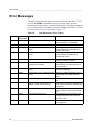
1
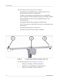
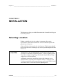
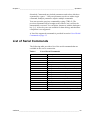
USER'S GUIDE
Vaisala Serial Wind Transmitter
WAC155
M210822EN-A
PUBLISHED BY
Vaisala Oyj
Phone (int.):
+358 9 8949 1
P.O. Box 26
Fax:
+358 9 8949 2227
FIN-00421 Helsinki
Finland
Visit our Internet pages at http://www.vaisala.com/
© Vaisala 2007
No part of this manual may be reproduced in any form or by any means,
electronic or mechanical (including photocopying), nor may its contents
be communicated to a third party without prior written permission of the
copyright holder.
The contents are subject to change without prior notice.
Please observe that this manual does not create any legally binding
obligations for Vaisala towards the customer or end user. All legally
binding commitments and agreements are included exclusively in the
applicable supply contract or Conditions of Sale.
________________________________________________________________________________
Table of Contents
CHAPTER 1
GENERAL INFORMATION . . . . . . . . . . . . . . . . . . . . . . . . . . . . . . . . . . . . . . 7
About This Manual . . . . . . . . . . . . . . . . . . . . . . . . . . . . . . . . . 7
Contents of This Manual . . . . . . . . . . . . . . . . . . . . . . . . . . . 7
General Safety Considerations . . . . . . . . . . . . . . . . . . . . . . 8
Feedback . . . . . . . . . . . . . . . . . . . . . . . . . . . . . . . . . . . . . . . 8
Product Related Safety Precautions . . . . . . . . . . . . . . . . . . . 8
ESD Protection . . . . . . . . . . . . . . . . . . . . . . . . . . . . . . . . . . . . 9
Recycling . . . . . . . . . . . . . . . . . . . . . . . . . . . . . . . . . . . . . . . . . 9
Warranty . . . . . . . . . . . . . . . . . . . . . . . . . . . . . . . . . . . . . . . . 10
CHAPTER 2
PRODUCT OVERVIEW . . . . . . . . . . . . . . . . . . . . . . . . . . . . . . . . . . . . . . . 11
Introduction to Vaisala Serial Wind Transmitter WAC155 11
CHAPTER 3
INSTALLATION . . . . . . . . . . . . . . . . . . . . . . . . . . . . . . . . . . . . . . . . . . . . . 13
Selecting Location . . . . . . . . . . . . . . . . . . . . . . . . . . . . . . . . 13
Installation Procedure . . . . . . . . . . . . . . . . . . . . . . . . . . . . . 15
Jumper Settings . . . . . . . . . . . . . . . . . . . . . . . . . . . . . . . . . 16
Connections . . . . . . . . . . . . . . . . . . . . . . . . . . . . . . . . . . . . . 17
Sensor Wiring . . . . . . . . . . . . . . . . . . . . . . . . . . . . . . . . . . 19
Signal Output . . . . . . . . . . . . . . . . . . . . . . . . . . . . . . . . . . . 20
Powering . . . . . . . . . . . . . . . . . . . . . . . . . . . . . . . . . . . . . . . . 21
Optional Heating Power . . . . . . . . . . . . . . . . . . . . . . . . . . . 22
Wiring Examples . . . . . . . . . . . . . . . . . . . . . . . . . . . . . . . . 24
Mounting . . . . . . . . . . . . . . . . . . . . . . . . . . . . . . . . . . . . . . . . 28
Mounting WAC155 to the Top of a Pole Mast . . . . . . . . . . 28
Mounting Wind Sensors to WAC155 . . . . . . . . . . . . . . . . . 29
Alignment . . . . . . . . . . . . . . . . . . . . . . . . . . . . . . . . . . . . . . 29
Verification . . . . . . . . . . . . . . . . . . . . . . . . . . . . . . . . . . . . . 30
CHAPTER 4
OPERATION . . . . . . . . . . . . . . . . . . . . . . . . . . . . . . . . . . . . . . . . . . . . . . . . 31
User Interface . . . . . . . . . . . . . . . . . . . . . . . . . . . . . . . . . . . . 31
Communication Interfaces . . . . . . . . . . . . . . . . . . . . . . . . . . 31
NMEA Message Format . . . . . . . . . . . . . . . . . . . . . . . . . . . 32
Polling Data using a Query . . . . . . . . . . . . . . . . . . . . . . . . 33
Service Connection . . . . . . . . . . . . . . . . . . . . . . . . . . . . . . 34
List of Serial Commands . . . . . . . . . . . . . . . . . . . . . . . . . . . 35
VAISALA ________________________________________________________________________ 1
________________________________________________________________________________
OPEN . . . . . . . . . . . . . . . . . . . . . . . . . . . . . . . . . . . . . . . . .36
CLOSE . . . . . . . . . . . . . . . . . . . . . . . . . . . . . . . . . . . . . . . .37
SETDEV . . . . . . . . . . . . . . . . . . . . . . . . . . . . . . . . . . . . . . .38
SETSPD . . . . . . . . . . . . . . . . . . . . . . . . . . . . . . . . . . . . . . .38
SETDIR . . . . . . . . . . . . . . . . . . . . . . . . . . . . . . . . . . . . . . .38
SETMES . . . . . . . . . . . . . . . . . . . . . . . . . . . . . . . . . . . . . .39
SETMEA . . . . . . . . . . . . . . . . . . . . . . . . . . . . . . . . . . . . . .40
SETCOM . . . . . . . . . . . . . . . . . . . . . . . . . . . . . . . . . . . . . .41
SETHEA . . . . . . . . . . . . . . . . . . . . . . . . . . . . . . . . . . . . . . .42
GETHEA . . . . . . . . . . . . . . . . . . . . . . . . . . . . . . . . . . . . . .42
SETALR . . . . . . . . . . . . . . . . . . . . . . . . . . . . . . . . . . . . . . .43
SERVICE TIMEOUT . . . . . . . . . . . . . . . . . . . . . . . . . . . . .44
GETSET . . . . . . . . . . . . . . . . . . . . . . . . . . . . . . . . . . . . . . .45
HELP . . . . . . . . . . . . . . . . . . . . . . . . . . . . . . . . . . . . . . . . .45
INIE . . . . . . . . . . . . . . . . . . . . . . . . . . . . . . . . . . . . . . . . . .45
RESET . . . . . . . . . . . . . . . . . . . . . . . . . . . . . . . . . . . . . . . .46
ERRS . . . . . . . . . . . . . . . . . . . . . . . . . . . . . . . . . . . . . . . . .46
CHAPTER 5
MAINTENANCE . . . . . . . . . . . . . . . . . . . . . . . . . . . . . . . . . . . . . . . . . . . . .49
Periodic Maintenance . . . . . . . . . . . . . . . . . . . . . . . . . . . . . .49
Visual Checking . . . . . . . . . . . . . . . . . . . . . . . . . . . . . . . . .49
Replacing Consumables . . . . . . . . . . . . . . . . . . . . . . . . . . . .49
Parts List for Consumables . . . . . . . . . . . . . . . . . . . . . . . .49
CHAPTER 6
TROUBLESHOOTING . . . . . . . . . . . . . . . . . . . . . . . . . . . . . . . . . . . . . . . .51
Problem Situations . . . . . . . . . . . . . . . . . . . . . . . . . . . . . . . .51
Error Messages . . . . . . . . . . . . . . . . . . . . . . . . . . . . . . . . . . .52
Technical Support . . . . . . . . . . . . . . . . . . . . . . . . . . . . . . . . .53
Return Instructions . . . . . . . . . . . . . . . . . . . . . . . . . . . . . . . .53
Vaisala Service Centers . . . . . . . . . . . . . . . . . . . . . . . . . . . .54
CHAPTER 7
TECHNICAL DATA . . . . . . . . . . . . . . . . . . . . . . . . . . . . . . . . . . . . . . . . . . .55
Specifications . . . . . . . . . . . . . . . . . . . . . . . . . . . . . . . . . . . .55
Dimensions in mm (inches) . . . . . . . . . . . . . . . . . . . . . . . . .57
2 _______________________________________________________________________________
________________________________________________________________________________
List of Figures
Figure 1
Figure 2
Figure 3
Figure 4
Figure 5
Figure 6
Figure 7
Figure 8
Figure 9
Figure 10
Figure 11
Figure 12
Figure 13
Figure 14
Figure 15
Figure 16
Figure 17
Figure 18
Figure 19
Vaisala Serial Wind Transmitter WAC155 . . . . . . . . . . . . . . . . 12
Recommended Mast Location in Open Area . . . . . . . . . . . . . . 14
Recommended Mast Length on Top of a Building . . . . . . . . . . 15
RS-485 Termination . . . . . . . . . . . . . . . . . . . . . . . . . . . . . . . . . 16
WAC155 Component Board. . . . . . . . . . . . . . . . . . . . . . . . . . . 17
Cable Shield Bent over the Plastic Sleeve and O-ring. . . . . . . 17
I/O Connectors . . . . . . . . . . . . . . . . . . . . . . . . . . . . . . . . . . . . . 18
Wiring of the Sensors. . . . . . . . . . . . . . . . . . . . . . . . . . . . . . . . 20
Typical System with 12 VDC Power Supply. . . . . . . . . . . . . . . 21
Heating Power Connection with 40 V Power Supply . . . . . . . . 22
Heating Power Connection with 20 V Power Supply . . . . . . . . 23
Heating Power Connection for Anemometer Only . . . . . . . . . . 23
Heating Power Connection for Wind Vane Only . . . . . . . . . . . 24
Basic Wiring with WAA151 and WAV151 Sensors . . . . . . . . . 25
Wiring with WHP151 Mains Power Supply . . . . . . . . . . . . . . . 26
Wiring with WHP25 Mains Power Supply and the WA252
Series Wind Sensors . . . . . . . . . . . . . . . . . . . . . . . . . . . . . . . . 27
Mounting WAC155 to the Top of a Pole Mast . . . . . . . . . . . . . 28
Installation of the Wind Sensors WAA151 and WAV151
to WAC155. . . . . . . . . . . . . . . . . . . . . . . . . . . . . . . . . . . . . . . . 29
WAC155 Dimensions . . . . . . . . . . . . . . . . . . . . . . . . . . . . . . . . 57
VAISALA ________________________________________________________________________ 3
________________________________________________________________________________
4 _______________________________________________________________________________
________________________________________________________________________________
List of Tables
Table 1
Table 2
Table 3
Table 4
Table 5
Table 6
Table 7
Table 8
Table 9
Table 10
Table 11
Table 12
Table 13
Table 14
Anemometer Connector (X1) Pinout . . . . . . . . . . . . . . . . . . . . . . 18
Power/Control Connector (X2) Pinout . . . . . . . . . . . . . . . . . . . . . 19
Wind Direction Sensor Connector (X3) Pinout. . . . . . . . . . . . . . . 19
WAC155 Default Serial Communication Settings . . . . . . . . . . . . 32
Checksum table . . . . . . . . . . . . . . . . . . . . . . . . . . . . . . . . . . . . . . 34
List of Serial Commands . . . . . . . . . . . . . . . . . . . . . . . . . . . . . . . 35
Meaning of the Command Line Elements . . . . . . . . . . . . . . . . . . 36
Available Spare Parts . . . . . . . . . . . . . . . . . . . . . . . . . . . . . . . . . 49
Problem Situations and Corrective Actions . . . . . . . . . . . . . . . . . 51
Self-diagnostics Error Codes . . . . . . . . . . . . . . . . . . . . . . . . . . . . 52
Performance . . . . . . . . . . . . . . . . . . . . . . . . . . . . . . . . . . . . . . . . 55
Inputs and Outputs. . . . . . . . . . . . . . . . . . . . . . . . . . . . . . . . . . . . 56
Operating Conditions . . . . . . . . . . . . . . . . . . . . . . . . . . . . . . . . . . 56
Dimensions and Mechanics . . . . . . . . . . . . . . . . . . . . . . . . . . . . . 56
VAISALA ________________________________________________________________________ 5
________________________________________________________________________________
6 _______________________________________________________________________________
Chapter 1 ________________________________________________________ General Information
CHAPTER 1
GENERAL INFORMATION
This chapter provides general notes for the manual and the product.
About This Manual
This manual provides information for installing and maintaining the
Vaisala Serial Wind Transmitter WAC155.
Contents of This Manual
This manual consists of the following chapters:
-
Chapter 1, General Information: This chapter provides general
notes for the manual and the product.
-
Chapter 2, Product Overview: This chapter introduces the features
of the Vaisala Serial Wind Transmitter WAC155.
-
Chapter 3, Installation: This chapter provides you with information
that is intended to help you install this product.
-
Chapter 4, Operation: This chapter contains information that is
needed to operate the Vaisala Serial Wind Transmitter WAC155.
-
Chapter 5, Maintenance: This chapter provides information that is
needed in basic maintenance of the Vaisala Serial Wind
Transmitter WAC155.
VAISALA ________________________________________________________________________ 7
User's Guide ______________________________________________________________________
-
Chapter 6, Troubleshooting: This chapter describes common
problems, their probable causes and remedies, and contact
information.
-
Chapter 7, Technical Data: This chapter provides technical data of
the Vaisala Serial Wind Transmitter WAC155.
General Safety Considerations
Throughout the manual, important safety considerations are highlighted
as follows:
WARNING
Warning alerts you to a serious hazard. If you do not read and follow
instructions very carefully at this point, there is a risk of injury or even
death.
CAUTION
Caution warns you of a potential hazard. If you do not read and follow
instructions carefully at this point, the product could be damaged or
important data could be lost.
NOTE
Note highlights important information on using the product.
Feedback
Vaisala Customer Documentation Team welcomes your comments and
suggestions on the quality and usefulness of this publication. If you find
errors or have other suggestions for improvement, please indicate the
chapter, section, and page number. You can send comments to us by email: [email protected].
Product Related Safety Precautions
The Vaisala Serial Wind Transmitter WAC155 delivered to you has
been tested for safety and approved as shipped from the factory. Note
the following precautions:
8 ____________________________________________________________________M210822EN-A
Chapter 1 ________________________________________________________ General Information
WARNING
Ground the product, and verify outdoor installation grounding
periodically to minimize shock hazard.
CAUTION
Do not modify the unit. Improper modification can damage the
product or lead to malfunction.
ESD Protection
Electrostatic Discharge (ESD) can cause immediate or latent damage to
electronic circuits. Vaisala products are adequately protected against
ESD for their intended use. However, it is possible to damage the
product by delivering electrostatic discharges when touching,
removing, or inserting any objects inside the equipment housing.
To make sure you are not delivering high static voltages yourself:
-
Handle ESD sensitive components on a properly grounded and
protected ESD workbench. When this is not possible, ground
yourself with a wrist strap and a resistive connection cord to the
equipment chassis before touching the boards. When neither of the
above is possible, at least touch a conductive part of the equipment
chassis with your other hand before touching the boards.
-
Always hold the boards by the edges and avoid touching the
component contacts.
Recycling
Recycle all applicable material.
Dispose of batteries and the unit according to statutory regulations.
Do not dispose of with regular household refuse.
VAISALA ________________________________________________________________________ 9
User's Guide ______________________________________________________________________
Warranty
Vaisala hereby represents and warrants all Products
manufactured by Vaisala and sold hereunder to be free
from defects in workmanship or material during a
period of twelve (12) months from the date of delivery
save for products for which a special warranty is given.
If any Product proves however to be defective in
workmanship or material within the period herein
provided Vaisala undertakes to the exclusion of any
other remedy to repair or at its own option replace the
defective Product or part thereof free of charge and
otherwise on the same conditions as for the original
Product or part without extension to original warranty
time. Defective parts replaced in accordance with this
clause shall be placed at the disposal of Vaisala.
Vaisala also warrants the quality of all repair and
service works performed by its employees to products
sold by it. In case the repair or service works should
appear inadequate or faulty and should this cause
malfunction or nonfunction of the product to which the
service was performed Vaisala shall at its free option
either repair or have repaired or replace the product in
question. The working hours used by employees of
Vaisala for such repair or replacement shall be free of
charge to the client. This service warranty shall be
valid for a period of six (6) months from the date the
service measures were completed.
This warranty is however subject to following
conditions:
a) A substantiated written claim as to any alleged
defects shall have been received by Vaisala within
thirty (30) days after the defect or fault became known
or occurred, and
b) The allegedly defective Product or part shall, should
Vaisala so require, be sent to the works of Vaisala or to
such other place as Vaisala may indicate in writing,
freight and insurance prepaid and properly packed and
labelled, unless Vaisala agrees to inspect and repair the
Product or replace it on site.
This warranty does not however apply when the defect
has been caused through
a) normal wear and tear or accident;
b) misuse or other unsuitable or unauthorized use of
the Product or negligence or error in storing,
maintaining or in handling the Product or any
equipment thereof;
c) wrong installation or assembly or failure to service
the Product or otherwise follow Vaisala's service
instructions including any repairs or installation or
assembly or service made by unauthorized personnel
not approved by Vaisala or replacements with parts not
manufactured or supplied by Vaisala;
d) modifications or changes of the Product as well as
any adding to it without Vaisala's prior authorization;
e) other factors depending on the Customer or a third
party.
Notwithstanding the aforesaid Vaisala's liability under
this clause shall not apply to any defects arising out of
materials, designs or instructions provided by the
Customer.
This warranty is expressly in lieu of and excludes all
other conditions, warranties and liabilities, express or
implied, whether under law, statute or otherwise,
including without limitation any implied warranties of
merchantability or fitness for a particular purpose and
all other obligations and liabilities of Vaisala or its
representatives with respect to any defect or deficiency
applicable to or resulting directly or indirectly from the
Products supplied hereunder, which obligations and
liabilities are hereby expressly cancelled and waived.
Vaisala's liability shall under no circumstances exceed
the invoice price of any Product for which a warranty
claim is made, nor shall Vaisala in any circumstances
be liable for lost profits or other consequential loss
whether direct or indirect or for special damages.
10 ___________________________________________________________________M210822EN-A
Chapter 2 __________________________________________________________ Product Overview
CHAPTER 2
PRODUCT OVERVIEW
This chapter introduces the features of the Vaisala Serial Wind
Transmitter WAC155.
Introduction to Vaisala Serial Wind Transmitter
WAC155
The Vaisala Serial Wind Transmitter WAC155 converts the digital data
supplied by the Vaisala 151 and 252 Series wind sensors for use in the
RS-485 bus. The WAC155 transmitter consists of a component board in
a junction box and a cross arm for mounting the wind sensors; see
Figure 1 on page 12.
The WAC155 unit is installed underneath the cross arm, and it
communicates with the controlling system via a twisted pair RS-485
cable. The electrical connections to the sensors are 6-bit parallel graycode for the direction measurement and up to 750Hz digital pulse for the
wind speed measurement (anemometer).
The power to the sensors is supplied through the WAC155 transmitter.
The transmitter accepts 9 ... 15.5 VDC as input power. The WAC155
transmitter also provides the sensors with a throughput for optional
heating power. The unit automatically connects the heating power in
temperatures below +3 °C (default setting).
VAISALA _______________________________________________________________________ 11
User's Guide ______________________________________________________________________
The main features of the WAC155 are as follows:
-
Communication with NMEA 0183 compliant protocol over
RS-485 electrical interface (half-duplex)
-
Capable of measuring the wind parameters at a configurable
interval using the instant method according to the WMO standard
-
Fail-safe RS-485 operation with configurable baud rate and
turnaround delay
-
Configurable RS-485 bus termination and ID setting
-
Service connection via the RS-485 interface for configuration and
maintenance
-
Adjustable heating control of the sensors
-
Automatic detection of sensor failure conditions
0710-010
Figure 1
Vaisala Serial Wind Transmitter WAC155
The following numbers refer to Figure 1 on page 12.
1
=
Flange for mounting a Vaisala anemometer
2
=
Junction box, containing the component board
3
=
Flange for mounting a Vaisala wind vane
12 ___________________________________________________________________M210822EN-A
Chapter 3 _______________________________________________________________ Installation
CHAPTER 3
INSTALLATION
This chapter provides you with information that is intended to help you
install this product.
Selecting Location
Finding a suitable site for the product is important for getting
representative ambient measurements. The site should represent the
general area of interest.
Allow sufficient clearance for the wind sensors. Wind sensors should
not be located next to a building or any other object that might affect the
flow of air.
CAUTION
Installations on top of high buildings or masts and in sites on open
grounds are vulnerable to lightning strikes. A nearby lightning strike
may induce a high-voltage surge not tolerable by the internal surge
suppressors of the instrument.
Additional protection is needed in regions with frequent, severe
thunderstorms, especially when long line cables (> 30m) are used.
Vaisala recommends using a surge protector such as the WSP150 in all
sites where there is an elevated risk of lightning strike.
VAISALA _______________________________________________________________________ 13
User's Guide ______________________________________________________________________
0204-040
Figure 2
Recommended Mast Location in Open Area
In general, any object of height (h) will not remarkably disturb wind
measurement at a minimum distance of 10 h. There should be at least
150 m open area in all directions from the mast. Refer to Figure 2 on
page 14.
14 ___________________________________________________________________M210822EN-A
Chapter 3 _______________________________________________________________ Installation
0204-041
Figure 3
Recommended Mast Length on Top of a Building
The recommended minimum length (marked with the letter h in Figure
3 on page 15) for the mast that is installed on top of a building is
1.5 times the height of the building (H). When the diagonal (W) is less
than the height (H), the minimum length of the mast is 1.5 W.
Installation Procedure
For installation, follow the procedure below and refer to corresponding
sections for details.
1.
Remove the four screws holding the cover of the WAC155
transmitter. Remove the cover.
2.
Select the RS-485 termination according to the instructions in
section Jumper Settings on page 16.
3.
Enter the power and signal cables through the cable glands(s).
For better protection against RF interference, ground the cable
shield as shown in Figure 6 on page 17.
4.
Connect the wires to the X2 removable screw terminal block
according to Figure 8 on page 20 and Figure 9 on page 21.
Tighten the output cable gland(s).
5.
Carefully reattach the enclosure cover with the four screws.
VAISALA _______________________________________________________________________ 15
User's Guide ______________________________________________________________________
6.
Attach the unit on the top of a pole mast with the mounting clamp
as shown in Figure 17 on page 28.
7.
Mount the sensors onto the cross arm. Refer to Figure 18 on page
29 and the sensors' manuals.
8.
Align the cross arm as instructed in section Alignment on page 29
before erecting the mast.
Jumper Settings
RS-485 serial bus termination can be selected with the on-board jumper.
Termination is on when pins 1 and 2 are shorted, and termination is off
when pins 2 and 3 are shorted or when the jumper plug is fully
disconnected. Termination is implemented by a 120 resistor on the
component board.
In a simple point-to-point configuration where only one WAC155
transmitter is used the jumper is always in ON position. In a multidrop
configuration where several WAC155 transmitters share the single
RS-485 communication line, the termination jumper is in ON position
only at the physically farthest transmitter (i.e. at the end of the
communication line), and in OFF position at the other transmitters.
0701-017
Figure 4
RS-485 Termination
16 ___________________________________________________________________M210822EN-A
Chapter 3 _______________________________________________________________ Installation
0702-001
Figure 5
WAC155 Component Board
The following numbers refer to Figure 5 on page 17.
1
=
RS-485 termination jumper
2
=
Status indicator LED
Connections
The WAC155 transmitter provides the line cable entry through a gland
for a cable with a diameter from 7 to 10 mm. For better protection
against RF interference, bend the cable shield as illustrated in Figure 6
on page 17.
0206-046
Figure 6
Cable Shield Bent over the Plastic Sleeve and O-ring
The WAC155 transmitter has three I/O connectors as shown in
Figure 7 on page 18. For the location of the connectors and the routing
of the cables through the cable glands, refer to Figure 8 on page 20.
VAISALA _______________________________________________________________________ 17
User's Guide ______________________________________________________________________
0702-008
Figure 7
I/O Connectors
The following numbers refer to Figure 7 on page 18.
X1 =
Plug-in connector with screw terminals (5 pcs) for the
anemometer cable. Maximum wire cross section area is 1.5
mm2.
X2 =
Plug-in connector with screw terminals (8 pcs) for the power
and signal cable. Maximum wire cross section area is 1.5
mm2.
X3 =
Plug-in connector with screw terminals (11 pcs) for the wind
vane cable. Maximum wire cross section area is 1.5 mm2.
I/O connector X1-X3 pinouts are shown in following tables.
Table 1
Anemometer Connector (X1) Pinout
Pin #
Signal
Description
1
2
3
4
5
F
F+
GND
HT1
HTC
Pulse input from sensor
Supply voltage output to sensor
Sensor ground
Heating supply-1 from connector X2
Heating common for heater serial connection
18 ___________________________________________________________________M210822EN-A
Chapter 3 _______________________________________________________________ Installation
Table 2
Power/Control Connector (X2) Pinout
Pin #
Signal
Description
1
2
3
4
5
6
7
8
HT1+
HT2Vin+
Vin+
VinVinRS-485 A(-)
RS-485 B(+)
Heating supply-1 input
Heating supply-2 input
Supply voltage input
Supply voltage input
Ground
Ground
RS-485 inverting I/O
RS-485 noninverting I/O
Table 3
Wind Direction Sensor Connector (X3) Pinout
Pin #
Signal
Description
1
2
3
4
5
6
7
8
9
10
11
HTC
HT2
GND
D+
G5
G4
G3
G2
G1
G0
n.c.
Heating common for heater serial connection
Heating supply-2 from connector X2
Sensor ground
Supply voltage output to sensor
Gray code input from sensor, bit-5
Gray code input from sensor, bit-4
Gray code input from sensor, bit-3
Gray code input from sensor, bit-2
Gray code input from sensor, bit-1
Gray code input from sensor, bit-0
Not connected
Sensor Wiring
The transmitter connects to the wind sensors with the cross-arm's
standard cables through two cable glands. Through these cables the
WAC155 transmitter both feeds the sensor power and receives the wind
data. Plug-in type screw terminal connectors are provided both for the
sensor cables and the output line cable.
VAISALA _______________________________________________________________________ 19
User's Guide ______________________________________________________________________
0702-007
Figure 8
Wiring of the Sensors
The following numbers refer to Figure 8 on page 20.
1
=
Anemometer cable
2
=
Glands for power and signal cables
3
=
Wind vane cable
Signal Output
The WAC155 transmitter provides a half-duplex RS-485 serial bus
connection. Wind data is provided in standard NMEA messages. In
addition, a service connection is available for configuration and status
information. The service connection is available through the same
RS-485 interface. When the service connection is in use, data
transmission and query are disabled.
Several transmitters can be connected to the same RS-485 bus. If only
a single transmitter is connected, the transmitter can be configured in
auto-transmit mode, i.e. the device transmits data messages at
configured intervals. If there are several transmitters in the same bus,
auto-transmission may not be enabled, and data must be polled using a
query.
20 ___________________________________________________________________M210822EN-A
Chapter 3 _______________________________________________________________ Installation
Each device in the same bus has a unique configurable ID, containing
1..5 characters. Alphabetical characters a-z and A-Z (case-sensitive) are
accepted, as well as numbers 0-9.
Typically, only a 4-wire shielded cable is required for the line between
the WAC155 transmitter and the receiving end. Two of the four wires
provide the operating power for the system. A twisted pair can be used
for the power wires to reduce interference. The other two wires are for
the RS-485 serial bus connection from the WAC155 transmitter.
The maximum length of an unisolated RS-485 line is 1200m (4000ft).
The cable used should be at least a twisted pair AWG 24 cable. The
achievable line length is affected by electrical noise and the number of
transmitters on the bus.
0702-002
Figure 9
Typical System with 12 VDC Power Supply
Powering
The WAC155 transmitter accepts 9 ... 15.5 VDC as input power.
The power line is protected against incorrect polarity. Transient
protection is accomplished with VDRs, series inductors and resistors,
and transient zener diodes on both the power line and each I/O line.
VAISALA _______________________________________________________________________ 21
User's Guide ______________________________________________________________________
Optional Heating Power
The WAC155 transmitter also provides the sensors with a throughput
for heating power, which can be connected if sensor heating is required.
The heating power is galvanically isolated from the operating power.
The heating power connection requires an extra pair of wires. Since the
heating elements in the shafts of the WAA151 and WAV151 sensors
typically consume some 500 mA each, the heating power is most
conveniently supplied from a local power source. Unit can
automatically connect heating power in temperatures below +3 °C
(default setting).
There are two ways to connect the heating power, depending on the
heating power supply available. The default way is to connect a 40 VAC
or VDC power supply in series; see Figure 10 on page 22. When a 40 V
power supply is used, 500 mA is required. The 40 V power supply can
only be used when both sensors are connected.
NOTE
If you connect DC heating power, observe the correct polarity of the
X2 connector pins 1 and 2 (HT1+ and HT2-).
0702-014
Figure 10
Heating Power Connection with 40 V Power Supply
If a 20 VAC or VDC power supply is used, the heating power should be
connected in parallel. The power supply must provide 500 mA for each
connected WAV151 and WAA151 sensor; 1 A is required when both
22 ___________________________________________________________________M210822EN-A
Chapter 3 _______________________________________________________________ Installation
sensors are connected. The parallel connection is illustrated in Figure 11
on page 23.
0702-019
Figure 11
Heating Power Connection with 20 V Power Supply
When a 20 V power supply is used, the heating power can also be
connected to a single sensor. Refer to Figure 12 on page 23 and Figure
13 on page 24.
0702-020
Figure 12
Heating Power Connection for Anemometer Only
VAISALA _______________________________________________________________________ 23
User's Guide ______________________________________________________________________
0702-021
Figure 13
Heating Power Connection for Wind Vane Only
Wiring Examples
Figure 14 on page 25 illustrates the basic wiring when the WAA151 and
WAV151 wind sensors are connected to the WAC155 transmitter.
Heating power is not connected in the figure.
Figure 15 on page 26 illustrates wiring with the WHP151 Mains Power
Supply, with heating power connected. Note that the WHP151 has
jumpers for configuring the power output. Connect pins 2-3 of the X5
jumper to set the correct voltage, and remove the X4 jumper to provide
continuous heating power. If you connect the heating in series to both
sensors as shown in the figure, set the heating power to 38 Vrms 0.5 A
by connecting pins 2-3 of the X8 jumper.
Figure 16 on page 27 illustrates the wiring with the WHP25 Mains
Power Supply and the WA252 series wind sensors. The WAC155
operating power is supplied from the WAA252 (+12Vout, F -> X2/3).
Thus no external operating voltage shall be applied to the connector X2.
NOTE
The expansion connector required for the high current wiring in Figure
16 on page 27 is included in the WAA252 accessories
24 ___________________________________________________________________M210822EN-A
Chapter 3 _______________________________________________________________ Installation
0702-005
Figure 14
Basic Wiring with WAA151 and WAV151 Sensors
VAISALA _______________________________________________________________________ 25
User's Guide ______________________________________________________________________
0702-022
Figure 15
Wiring with WHP151 Mains Power Supply
26 ___________________________________________________________________M210822EN-A
Chapter 3 _______________________________________________________________ Installation
0702-006
Figure 16
Wiring with WHP25 Mains Power Supply and the
WA252 Series Wind Sensors
VAISALA _______________________________________________________________________ 27
User's Guide ______________________________________________________________________
Mounting
Mounting WAC155 to the Top of a
Pole Mast
Figure 17 on page 28 illustrates mounting of the WAC155 transmitter
to the top of a Ø 60 mm pole mast using the standard mounting clamp.
The arrow on the cover of the junction box must point to north.
0206-059
Figure 17
NOTE
Mounting WAC155 to the Top of a Pole Mast
A long cable between different units (sensors, transmitters, power
supplies, and displays) can cause a lethal surge voltage if a lightning
strikes in the vicinity. Always ground the mast equipment case close
to the mast with a short low-resistance cable.
28 ___________________________________________________________________M210822EN-A
Chapter 3 _______________________________________________________________ Installation
Mounting Wind Sensors to WAC155
0110-005
Figure 18
Installation of the Wind Sensors WAA151 and
WAV151 to WAC155
The following numbers refer to Figure 18 on page 29.
1
=
WAA151 Cup assembly
2
=
WAV151 Tail assembly
3
=
Cross arm
4
=
WAC155
5
=
Connector
6
=
Mounting flange
7
=
South
8
=
North
Alignment
After mounting the WAC155 transmitter to the mast, check that the
WAV151 end of the cross arm is pointing to north with the required
accuracy, see Figure 17 on page 28. To ensure a correct assembly after
aligning the WAC155, you can mount the sensors on it only in one way.
VAISALA _______________________________________________________________________ 29
User's Guide ______________________________________________________________________
Verification
Monitor the status indicator LED when powering up the WAC155
transmitter. The LED will flash green if the self-diagnostics are
completed without errors, and red if there is an error condition.
An error condition may be caused by an erroneous installation,
configuration, or a combination of both. For example, enabling sensor
heating without connecting the heating power will cause an error state.
You may be able to diagnose the problem using the service connection.
Howerver, if the problem is with the operating power, the service
connection may not be available even if the LED is flashing.
If the signal cable from the WAC155 transmitter is connected to a data
collection system and the system is powered up, check that the wind
readings react correctly. For testing the anemometer, rotate the cups
manually. For testing the wind vane, hold the vane in a few fixed angles
and verify the data.
30 ___________________________________________________________________M210822EN-A
Chapter 4 ________________________________________________________________ Operation
CHAPTER 4
OPERATION
This chapter contains information that is needed to operate the Vaisala
Serial Wind Transmitter WAC155.
User Interface
The WAC155 does not provide a direct user interface, except for a
status indicator LED on the component board. The LED will flash green
when the operational status is OK, and red when there is an error
condition. The LED is activated for five minutes after the transmitter is
powered up. The LED is also activated when the service connection is
open.
The red LED does not indicate the type of the error. Service personnel
must connect to the service connection to resolve the problem.
Data and service connections are provided over the RS-485 interface.
These connections are described in the next section.
Communication Interfaces
The WAC155 transmitter communicates over a half-duplex RS-485
interface. The WAC155 can be configured to send wind data messages
at regular intervals (auto-transmit mode), and it can provide the data as
a response to an MWV query. The data is provided in standard NMEA
wind speed and angle messages. In addition, a service interface is
available for configuration and status information.
VAISALA _______________________________________________________________________ 31
User's Guide ______________________________________________________________________
More than one transmitter can be connected to a single RS-485 bus.
In the case of single transmitter, the auto-transmit mode can be used (the
device transmits data messages with configured interval). If there are
several transmitters in the same bus, auto-transmission may not be
enabled, and data can be only polled by query.
Each device in the same bus has a unique configurable ID, containing
1..5 characters. Alphabetical characters a-z and A-Z (case-sensitive) are
accepted, as well as numbers 0-9.
Table 4
WAC155 Default Serial Communication Settings
Property
Description / Value
Baud rate
Data bits
Parity
Stop bits
9600
8
none
1
NMEA Message Format
The NMEA specification defines wind speed and angle message MWV
as follows:
$WIMWV,<a.a>,<R>,<s.s>,<U>,<S>*<CS><cr><lf>
where
$WIMWV =
Fixed text at the start of the message
<a.a>
=
Wind angle, 0..359 degrees
<R>
=
Reference: R=relative, T=theoretical
<s.s>
=
Wind speed
<U>
=
Units: K=km/h, M = m/s, N=knots
<S>
=
Status: A=valid, V=invalid
*
=
Asterisk, indicating that the next field is the checksum
<CS>
=
Two character checksum for the message
The comma "," is used as a separator between the fields. Here are some
examples of MWV messages output by the WAC155:
32 ___________________________________________________________________M210822EN-A
Chapter 4 ________________________________________________________________ Operation
$WIMWV,39,R,1.3,M,A*06
$WIMWV,39,R,0.5,M,A*01
$WIMWV,61,R,1.0,M,A*08
$WIMWV,59,R,1.2,M,A*01
$WIMWV,53,R,1.5,M,A*0c
$WIMWV,46,R,1.2,M,A*0f
$WIMWV,70,R,1.1,M,A*09
Polling Data using a Query
Polling for the MWV messages can be done using the following
command:
$WIP<ID>Q,*<CS><cr><lf>
where
$WIP=
Fixed text at the start of the query
<ID> =
Transmitter device ID
Q
=
Marks the message as a query
*
=
Asterisk, indicating that the next field is the checksum
<CS>=
Two character checksum for the device ID
The data in the response follows the MWV message format, but the
header is slightly different:
$P<ID>MWV,<a.a>,<R>,<s.s>,<U>,<S>*<CS><cr><lf>
where
$P
=
Fixed text at the start of the response
<ID> =
Transmitter device ID
MWV =
Marks the message as a wind speed and angle message
After receiving a query that uses its device ID, the transmitter will reply
with an MWV message containing the wind data. However, if you have
not defined any messages of the type mwvmessage using the SETMES
command, the transmitter will not respond.
Example polling command for transmitter with device ID "A":
$WIPAQ,*72
VAISALA _______________________________________________________________________ 33
User's Guide ______________________________________________________________________
Example response:
$PAMWV,50,R,0.0,M,A*04
Table 5 on page 34 provides checksums and polling strings for some
typical device IDs.
Table 5
Checksum table
ID Character <id>
Checksum <CS> Polling String
A
B
C
D
E
F
G
H
I
J
K
L
M
N
O
72
71
70
77
76
75
74
7B
7A
79
78
7F
7E
7D
7C
$WIPAQ,*72<cr><lf>
$WIPBQ,*71<cr><lf>
$WIPCQ,*70<cr><lf>
$WIPDQ,*77<cr><lf>
$WIPEQ,*76<cr><lf>
$WIPFQ,*75<cr><lf>
$WIPGQ,*74<cr><lf>
$WIPHQ,*7B<cr><lf>
$WIPIQ,*7A<cr><lf>
$WIPJQ,*79<cr><lf>
$WIPKQ,*78<cr><lf>
$WIPLQ,*7F<cr><lf>
$WIPMQ,*7E<cr><lf>
$WIPNQ,*7D<cr><lf>
$WIPOQ,*7C<cr><lf>
Service Connection
The service connection allows you to configure the device and gather
status information. The same physical RS-485 interface connection is
used for both the data transmission and the service connection. When
the service connection is opened (using the OPEN command), the data
transmission and query are disabled as long as the service connection
remains open.
When you change any parameters using the service connection,
remember that a reset (or a power-up) is required to take the new
parameters into use.
The commands are not case-sensitive; formats 'COMMAND',
'command', 'Command' and all other combinations of upper and lower
case letters are accepted. However, the device ID is case-sensitive.
Commands are entered on a single line, terminated by a line feed <lf>
or carriage-return <cr> characters. If the terminal provides both
characters as the line end marker, the second EOL character is silently
34 ___________________________________________________________________M210822EN-A
Chapter 4 ________________________________________________________________ Operation
discarded. Commands may include parameters and values which are
separated by a space ' '. Only one parameter can be set with a single
command; multiple parameters require multiple commands.
You can repeat the previous command by typing CTRL+P. The
previous command will be brought to the console, but it will not be
automatically executed. You can delete characters with the backspace
key [<=]. Arrow keys are not available for data editing, and tabulator
completion is not supported.
A list of the supported commands is provided in section List of Serial
Commands on page 35.
List of Serial Commands
The following table provides a list of the serial commands that are
available in the service connection.
Table 6
List of Serial Commands
Command
Description
OPEN
CLOSE
HELP
SETDEV
SETMEA
SETSPD
SETDIR
SETMES
SETCOM
SETALR
SETHEA
GETHEA
SERVICE TIMEOUT
GETSET
ERRS
INIE
RESET
Open the service connection
Close the service connection
Display the command list
Set the ID of the transmitter
Configure measurement parameters
Configure wind speed computation time period
Configure wind direction computation time period
Specify data transmission mode
Configure communication ports
Configure sensor stuck supervision functionality
Configure wind sensor heating control
Display the current heating status
Configure timeout for service connection
Display the current settings of the device
Display the current error status
Reset the transmitter to factory default settings
Reset the transmitter to new settings
VAISALA _______________________________________________________________________ 35
User's Guide ______________________________________________________________________
The sections below contain a description of each command. The
meaning of the command line elements is presented in the table below.
Table 7
Meaning of the Command Line Elements
Element
Meaning
Text Style Used
SAMPLE
Specifies the name of
the command or utility.
Indicates a set of
choices from which the
user must choose one,
several or all.
Indicates optional items.
UPPER CASE BOLD
{variable}
[option]
<value>
Specifies the value for
the option
Punctuation marks are
considered as part of
the command and
should be included as
they are.
Stands for pressing
ENTER (on your
computer keyboard)
.,:;
<cr>
lower case enclosed in
{braces}
lower case enclosed in
[brackets]
lower case enclosed in
<angle brackets>
lower case
lower case
OPEN
The OPEN command establishes service communication with the
transmitter. Transmitter configuration commands are effective only
when the service connection is open.
OPEN [id]<cr>
where
id
= Case-sensitive device ID that specifies the transmitter
where the service connection is opened. Must be specified
if a device ID has been set for the transmitter, or if there are
multiple transmitters on the same RS-485 bus.
If there is only one transmitter on the RS-485 bus, and no device ID has
been set for the transmitter using the SETDEV command, you can open
the service connection without specifying the ID. The device ID can be
1..5 characters (a-z, A-Z, 0-9).
36 ___________________________________________________________________M210822EN-A
Chapter 4 ________________________________________________________________ Operation
If there are multiple transmitters on the same bus, you should always
open the service connection so that you specify the device ID. Do not
install multiple transmitters on the same bus without assinging a
different device ID for each transmitter.
NOTE
If you do not know the device ID of a transmitter, you can open the
service connection by using the dollar sign "$" as the device ID:
OPEN $
Only use this command when you have a single transmitter on the bus.
The service connection will remain open until it is closed by the
CLOSE command, or until the defined service timeout expires (i.e., no
commands have been given within the defined timeout period). The
timeout period is configured using the SERVICETIMEOUT
command. Once the service connection is closed, the transmitter will
return into the operation state it had prior to opening the connection,
either auto-transmitting or polling mode.
Example:
>open
Vaisala Serial Wind Transmitter WAC155
SW version 2.0.7
Service connection opened
>
CLOSE
The CLOSE command closes all current service connections. It is not
necessary to define the device ID. Note that new parameters are not
automatically taken into use when the service connection is closed; you
must reset or power cycle the transmitter to do that.
CLOSE<cr>
Example:
>close
Service connection closed
>
VAISALA _______________________________________________________________________ 37
User's Guide ______________________________________________________________________
SETDEV
The SETDEV command sets the device ID of the transmitter. In a
multi-transmitter network, the device ID of each transmitter must be
unique.
SETDEV id <value><cr>
where
value
= Specifies the new device ID for the transmitter. The
ID may contain up to 5 characters, including A-Z, az, and 0-9. The ID is case-sensitive.
Example:
>setdev id A1
ID=A1
>
SETSPD
The SETSPD command configures the wind speed computation time
period.
SETSPD average <value><cr>
where
value
= Wind speed computation time period in seconds. Range
0.25 ... 5.00 in 0.25 second increments (default 3.00)
Example:
>setspd average 3.00
AVERAGE=3.00
>
SETDIR
The SETDIR command configures the wind direction computation
time period.
38 ___________________________________________________________________M210822EN-A
Chapter 4 ________________________________________________________________ Operation
SETDIR average <value>
where
value
= Wind direction computation time period in seconds. Range
0.25 ... 5.00 in 0.25 second increments (default 3.00)
Example:
>setdir average 3.00
AVERAGE=3.00
>
SETMES
The SETMES command specifies the data transmission mode. The
transmitter can support four (4) different messages at a time. Each
message has its own settings for the message type and transmit interval.
Three message types are supported:
-
NONE (no message)
-
MWV (standard wind speed and direction message)
-
MWVQUERY (Vaisala extension to MWV message)
SETMES {messagenumber} [type] [interval] <value><cr>
where
messagenumber = The number of the message to configure. Range 0
... 3
type
= Configures the message type. Possible values:
NONE
MWV
MWVQUERY
interval
= Configures the transmit interval. Zero value
disables data auto-transmission. Possible values: 0
... 600.00 in 0.25 second increments
value
= The value for the option.
VAISALA _______________________________________________________________________ 39
User's Guide ______________________________________________________________________
Example:
>setmes 1 type mwvquery
0 TYPE=NONE INTERVAL=0.00
1 TYPE=MWVQUERY INTERVAL=1.00
2 TYPE=NONE INTERVAL=0.00
3 TYPE=NONE INTERVAL=0.00
>
SETMEA
The SETMEA command configures measurement parameters. The
configurable parameters include anemometer transfer function
parameters gain and offset.
SETMEA [allowedspdchange] [maxinvalidspdcount] [gaincorr]
[offset] [powersave] <value><cr>
where
allowedspdchange = Maximum allowed difference between two
adjacent samples in the sensor data, range
0.1 ... 25.0 (default 10.0)
maxinvalidspdcount = Maximum number of adjacent discarded
samples in the sensor data. Sensor data sanity
check functionality is enabled if this value is
not zero. Range 0 ... 15 (default 2)
gaincorr
= Anemometer transfer function gain parameter.
Range 0.0 … 10.0 (default 0.09853)
offset
= Anemometer transfer function offset
parameter. Range -10.0 … 10.0 (default
0.4054)
powersave
= Defines whether sensor power is pulsed or
provided continuously. Pulsing saves power,
since the sensors are only powered when they
are being read.
0 = continuous power
1 = pulsed power (default)
value
= Defines the value for the option.
40 ___________________________________________________________________M210822EN-A
Chapter 4 ________________________________________________________________ Operation
Example:
>setmea offset 0.318
GAIN = 0.09853
OFFSET = 0.31800
POWERSAVE = 1
ALLOWEDSPDCHANGE = 10.0
MAXINVALIDSPDCOUNT = 2
>
SETCOM
The SETCOM command configures the communication ports. Default
communication port settings are 9600-n-8-1.
SETCOM [portnumber] [baudrate] [databits] [stopbits] [parity]
[txddelay] <value><cr>
where
portnumber= The number of the COM port to configure, 0 or 1. If
omitted, the configuration will apply to the current port
in use.
baudrate
= The baud rate of the port. Possible values: 300 600 1200
2400 4800 9600 19200
databits
= The number of data bits, 7 or 8
stopbits
= The number of stop bits, 1 or 2
parity
= The parity to be used. Possible values: ODD EVEN
NONE
txddelay
= The RS-485 half-duplex transmission turn-around delay
in milliseconds, range 0 .. 200
value
= The value for the option.
Example:
>setcom baudrate 9600
BAUDRATE = 9600
DATABITS = 8
PARITY
= NONE
STOPBITS = 1
TXDDELAY = 30
>
VAISALA _______________________________________________________________________ 41
User's Guide ______________________________________________________________________
SETHEA
The SETHEA command configures the wind sensor heating control.
Sensor heating is provided to prevent frost in sensor bearings. Heaters
are powered by an external power supply, which is not the same as the
sensor system power supply. Heating is not enabled by default. If
necessary, heating can also be forced.
SETHEA [active] [tos] [thys] <value><cr>
where
active
= Enables the wind sensor heating functionality. Possible
values: 0 = disabled (default) 1 = enabled 2 = forced
tos
= Control limit for heating in degrees Celcius, range 55…+125 (default 4)
thys
= Thermal hysteresis in degrees Celcius, range -55…+125
(default 1)
value
= The value for the option
If heating is enabled, it is turned on when temperature drops below
TOS-THYS. Heating is turned off when temperature rises above
TOS+THYS. With the default values of TOS=4 and THYS=1, heating
is enabled at +3 °C, and disabled at +5 °C.
Typical commands:
SETHEA ACTIVE 1 (enable sensor heating)
SETHEA TOS 3 (set heating control limit to 3 degrees Celcius)
Example:
>sethea
ACTIVE
TOS
THYS
>
active 1
= 1
= 4.00
= 1.00
GETHEA
The GETHEA command displays the current heating status and
temperature.
42 ___________________________________________________________________M210822EN-A
Chapter 4 ________________________________________________________________ Operation
GETHEA<cr>
Example:
>gethea
Heating OFF
Temperature 14.25
>
SETALR
The WAC155 can monitor the wind sensor movement to detect if the
sensors appear to be stuck in place. The SETALR command is used to
configure this functionality.
If the functionality is enabled and timeouts are not zero, sensors are
cross-checked for changes, i.e. if the reading of the other sensor
changes, but the other one does not for certain period of time, the sensor
is considered stuck.
SETALR [active] [dir] [spd] [calm] [dirlimit] [spdlimit] <value><cr>
where
active
= Enables the wind sensor stuck supervision functionality. 0
or 1 (default 0)
dir
= Timeout for wind direction change, range 0 ... 256 (default
60)
spd
= Timeout for wind speed change, range 0 ... 256 (default 60)
calm
= The calm timeout. Defines how long both sensors may be
unchanged until both sensors are considered being stuck.
Range 0 ... 65535 (default 1440)
dirlimit = Threshold limit for wind direction change. If the wind
direction change is below the threshold, it is considered
unchanged from the wind sensor stuck functionality point
of view. Range 0 ... 180 (default 3)
spdlimit = Threshold limit for wind speed change. If the wind speed
change is below the threshold, it is considered unchanged
from the wind sensor stuck functionality point of view.
Range 0.0 ... 10.0 (default 0.0)
value
= The value for the option
VAISALA _______________________________________________________________________ 43
User's Guide ______________________________________________________________________
Typical commands:
SETALR ACTIVE 1 (activate the alarm functionality)
SETALR DIR 60 (alarm if wind vane stuck for 60 seconds)
SETALR SPD 60 (alarm if anemometer stuck for 60 seconds)
SETALR CALM 1440 (alarm if both sensors stuck for 1440 minutes)
Example:
>setalr active 1
ACTIVE= 1
DIR= 60
SPD= 60
CALM= 1440
DIRLIMIT= 3
SPDLIMIT= 0.0
>
SERVICE TIMEOUT
The SERVICE TIMEOUT command configures the timeout period of
the auto-close function of the service connection. If no data is input
within the configured time interval, the connection will close itself and
the device returns it normal operational state.
Zero value disables the auto-close function, which means that the
service connection will never close unless explicitly closed using the
CLOSE command.
SERVICE TIMEOUT <value><cr>
where
value
= The value of the service timeout, range 0 ... 30 min (default
5 min).
Example:
>service timeout 5
TIMEOUT=5
>
44 ___________________________________________________________________M210822EN-A
Chapter 4 ________________________________________________________________ Operation
GETSET
The GETSET command will return the current configuration of the
current unit.
GETSET <cr>
Example:
>getset
SETDEV
ID=A1
SETSPD
AVERAGE=3.00
SETDIR
AVERAGE=3.00
…
HELP
The HELP command displays a list of the supported commands.
HELP<cr>
Example:
>help
CLOSE Close service connection
SETDEV Set device ID
SETSPD Speed computation average length
SETDIR Direction computation average length
...
INIE
The INIE command resets the transmitter to factory defaults. Note that
the current configuration settings will be lost. Before using the INIE
command, it may be a good idea to view the current settings using the
GETSET command , and record the output.
After using this command, you have to use the RESET command to
take the factory defaults into use, and re-open the service connection
with the OPEN command.
INIE <cr>
VAISALA _______________________________________________________________________ 45
User's Guide ______________________________________________________________________
Example:
>inie
FACTORY DEFAULTS
>
RESET
The RESET command resets the transmitter, and takes any new
configuration settings into use. After using this command, you have to
re-open the service connection with the OPEN command.
RESET <cr>
Example:
>RESET
Wait 5 seconds delay...
ERRS
When issued alone without the [mask] option, the ERRS command
returns the current error status of the transmitter. Possible errors, their
codes, and the corresponding hexadecimal values are described inTable
10 on page 52.
You can use the [mask] option to define the set of errors that causes
NMEA messages to be marked as invalid. The error mask is a
hexadecimal number formed by combining the hexadecimal values of
the desired errors. By default the mask is 0010 which means that only if
both wind sensors are missing or broken, the NMEA data is invalid.
For example, if you want the mask to include errors 10 and 11 (0400 and
0800 in hex) , the desired mask value is 0C00:
0400 + 0800 = 0C00
46 ___________________________________________________________________M210822EN-A
Chapter 4 ________________________________________________________________ Operation
ERRS [mask] <value><cr>
where
mask
= Implements an error mask.
value
= The value for the error mask in hexadecimal format
(default 0010).
Example:
>errs
Active errors:
ERROR 5: Heating control broken or heating power missing
ERRS = 0020
MASK = 0010
>
VAISALA _______________________________________________________________________ 47
User's Guide ______________________________________________________________________
48 ___________________________________________________________________M210822EN-A
Chapter 5 ______________________________________________________________ Maintenance
CHAPTER 5
MAINTENANCE
This chapter provides information that is needed in basic maintenance
of the Vaisala Serial Wind Transmitter WAC155.
Periodic Maintenance
Visual Checking
Check every 1 to 2 years that the component board is not corroded.
Replacing Consumables
When replacing the component board, read carefully the section
ESD Protection on page 9.
Parts List for Consumables
Table 8
Available Spare Parts
Spare Part
Order Code
Component Board for WAC155
Sensor Cable for Anemometer (0.8m)
Sensor Cable for Wind Vane (0.8m)
WAC155CB
ZZ45036
ZZ45037
VAISALA _______________________________________________________________________ 49
User's Guide ______________________________________________________________________
50 ___________________________________________________________________M210822EN-A
Chapter 6 ___________________________________________________________ Troubleshooting
CHAPTER 6
TROUBLESHOOTING
This chapter describes common problems, their probable causes and
remedies, and contact information.
Problem Situations
Table 9
Problem Situations and Corrective Actions
Problem
Possible cause
Action
Data is not received by the data
collecting system
Improper or loose connections.
Check wiring and tighten the
screw terminals.
Check and correct using the
service connection.
Check that the power supply is
online.
Check wiring and tighten the
screw terminals.
Check and correct using the
service connection.
Check that the power supply is
online.
Incorrect messaging settings.
Power failure.
Shaft heating of the sensors is
not working.
Heating power is not connected
properly.
Heating is not enabled in the
transmitter settings.
Power failure of the heating
power supply.
VAISALA _______________________________________________________________________ 51
User's Guide ______________________________________________________________________
Error Messages
The table below describes the error codes defined in the WAC155. If
you use the ERRS command to specify an error mask, use the
hexadecimal values that are provided in the table. For help in using the
service connection to read the errors and configure the WAC155, refer
to section List of Serial Commands on page 35.
Table 10
Error #
Hex
Message
equivalent
0
0001
1
2
0002
0004
3
0008
4
0010
5
0020
6
0040
7
0080
8
0100
9
0200
10
0400
11
0800
12
1000
Self-diagnostics Error Codes
Description
Input voltage too low
Input voltage below accepted limit,
sensor behaviour not defined
Input voltage too high
Over-voltage condition
Wind speed sensor missing or
Self-diagnostics does not detect the
broken
proper voltage drop caused by an
operational sensor
Wind direction sensor missing or
Self-diagnostics does not detect the
broken
proper voltage drop caused by
operational sensor
Both sensors missing or broken
Wind speed and direction sensors
are both missing or broken
Heating control malfunction or
Heating power control mechanism
heating power missing
malfunctioning or heating power is
not connected
Erroneous reading from temperature Internal temperature sensor gives
sensor
erroneous readings
Internal error in non-volatile memory Storing or reading parameters from
access
the internal non-volatile memory
failed
Internal error
This error code is reserved for future
use
Temperature sensor not calibrated.
Production time calibration not
Heating control malfunctioning.
performed, temperature readings are
erroneous
Wind direction sensor stuck
The wind vane has not turned for a
certain period, but the anemometer
has
Wind speed sensor stuck
Anemometer has not turned for the
configured period of time, but the
wind vane has
Both wind sensors stuck
Both wind sensors have not turned
for a long time
52 ___________________________________________________________________M210822EN-A
Chapter 6 ___________________________________________________________ Troubleshooting
Technical Support
For technical questions, contact the Vaisala technical support:
E-mail
[email protected]
Fax
+358 9 8949 2790
Return Instructions
If the product needs repair, please follow the instructions below to
speed up the process and to avoid extra costs to you.
1.
Read the section Warranty on page 10.
2.
Contact a Vaisala Service Center or a local Vaisala representative.
The latest contact information and instructions are available from
www.vaisala.com. Addresses of the Service Centers are provided
in section Vaisala Service Centers on page 54.
Please have the following information on hand:
-
serial number of the unit
-
date and place of purchase or last calibration
-
description of the fault
-
circumstances in which the fault occurs/occurred
-
name and contact information of a technically competent
person who can provide further information on the problem
3.
Pack the faulty product in a strong box of adequate size, with
proper cushioning material to avoid damage.
4.
Include the information specified in step 2 in the box with the
faulty product. Also include a detailed return address.
5.
Ship the box to the address specified by your Vaisala contact.
VAISALA _______________________________________________________________________ 53
User's Guide ______________________________________________________________________
Vaisala Service Centers
Vaisala Service Centers perform calibrations and adjustments as well as
repair and spare part services. See contact information below.
Vaisala Service Centers also offer accredited calibrations, maintenance
contracts, and a calibration reminder program. Do not hesitate to
contact them to get further information.
./24(!-%2)#!.3%26)#%#%.4%2
6AISALA)NC$'ILL3TREET7OBURN-!53!
0HONE&AX
%MAILUSCUSTOMERSUPPORT VAISALACOM
%52/0%!.3%26)#%#%.4%2
6AISALA)NSTRUMENTS3ERVICE6ANHA.URMIJÊRVENTIE&).6ANTAA&).,!.$
0HONE&AX
%MAILINSTRUMENTSSERVICE VAISALACOM
4/+9/3%26)#%#%.4%2
6AISALA+++AGURAZAKA#HOME3HINJUKU+U4OKYO*!0!.
0HONE&AX
%MAILAFTERSALESASIA VAISALACOM
"%)*).'3%26)#%#%.4%2
6AISALA#HINA,TD&LOOR%!3"UILDING.O8IAO9UN2OAD$ONGSANHUAN"EILU
#HAOYANG$ISTRICT"EIJING02#().!
0HONE&AX
%MAILCHINASERVICE VAISALACOM
ZZZYDLVDODFRP
54 ___________________________________________________________________M210822EN-A
Chapter 7 ____________________________________________________________ Technical Data
CHAPTER 7
TECHNICAL DATA
This chapter provides technical data of the Vaisala Serial Wind
Transmitter WAC155.
Specifications
Table 11
Performance
Property
Description/Value
Equipment type
Digital-to-RS-485 serial bus converter for
Vaisala wind sensors
Full scale:
for direction
for speed
Resolution:
for direction
for speed
Updating interval:
for direction
for speed
Pulse-mode power feed:
to the vane
to the anemometer
0 ... 360°
0 ... 75 m/s
5.625° (1.4° achieved by calculation)
0.1 m/s
3 s (default)
3 s (default)
500 µs / 4 Hz Nominal
50 µs / 2400 Hz Nominal
VAISALA _______________________________________________________________________ 55
User's Guide ______________________________________________________________________
Table 12
Inputs and Outputs
Property
Description/Value
Signal input:
wind direction
wind speed
Input operating power
6-bit parallel GRAY code
Pulse frequency 0 ... 750 Hz
9 ... 15.5 VDC, 8 mA typical incl. sensors
(when power-save mode is enabled)
Maximum operating power 50 mA (when power-save mode is disabled)
Input heating power
16 ... 24 VAC or VDC
32 ... 48 VAC or VDC can be used when
heating power is connected in series to both
sensors
Typical heating power
500 mA per sensor
Output signals
RS-485 serial bus
Signal cable
4 wires minimum: VIN+, VIN-, RS-485 A(-),
RS-485 B(+)
Table 13
Operating Conditions
Property
Description/Value
Temperature range:
operating
storage
Humidity
-55 ... +55 °C
-60 ... +70 °C
0 ... 100 %RH
Table 14
Dimensions and Mechanics
Property
Dimensions:
printed circuit board
jucntion box
Cross arm length
Ingress protection
Mounting
Weight
Material:
cross arm
junction box
Description/Value
115 × 58 mm2
125 (w) × 80 (h) × 57 (d) mm
800 mm
IP65
To a Ø 60 mm pole mast
1.5 kg
AI anodized
AI painted gray
56 ___________________________________________________________________M210822EN-A
Chapter 7 ____________________________________________________________ Technical Data
Dimensions in mm (inches)
0702-009
Figure 19
WAC155 Dimensions
VAISALA _______________________________________________________________________ 57
www.vaisala.com
*M210822EN*