1
Save This Manua!_
For Future Reference
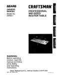
owners
manual
MODEL NO.
171.25490
CRRFTSMRH
INDUSTRIAL
ROUTER
TABLE
CAUTION:
READ ALL
INSTRUCTIONS
• assemb y
CAREFULLY
, operatinq
Sold bY SEARS.
_
_ CO.,_.....
_
....
ROEBU(_KiAND
CH|CAGO,_i
L 6068_, U.S.A.
Printed In U.S.A.
49LCN-39
WARNING:
FAILURE CAN
TO HEED
ALL INSAFETY
OPERATING
OF THIS PRDDUCT
RESULT
SERIOUSANDBODILY
INJURY.INSTRUCTIONS
AND WARNINGS
REGARDING
!
UI_tEI
°
GENERAL SAFETY INSTRUCTIONS
FOR POWER TOOLS
1. KNOW YOUR POWER TOOL
Read the owner's manual carelulty. Learn _ISapplicalion and
hmitations as we!l as the spot=tic potential hazards peculiar
Io thrs tool.
13. SECURE WORK
Use clamps or a wse ,'o hold work when practical. Its safer
than using Four hand trees both hands to operate tool.
2. GROUND ALL TOOLS (UNLESS DOUBLE
INSULATED)
14. DON'T OVERREACH
Keep proper fooling arid balance at all limes.
If tool is equipped with
3-prong grounding type
receptacle.
The green
0ng wire. Never connect
an _pproved 3-conductor cord end a
plug to tJ_.the proper grounding type
cor:_,,ctor in the card ts the groundme green w=re to a lwe terminal.
3. KEEP GUARDS IN PLACE
in working order, and _nprope:"ad}ustmenI ar,d ahgnmenl.
15. MAINTAIN TOOLS WITH CARE
Keeps tools sharp and clean for best and safest parlormanta. Follow instructio'ls for lubricalmg and changing
accessorieS,
16,
4. REMOVE ADJUSTING
KEYS AND WRENCHES
Form habit of checking tc see that keys and adjusbng
wrenches are removed 1ramtool before turning ]t on.
5. KEEP WORK AREA CLEAN
Cluttered areas ana ber_cnes _rvlte a-"c;cents. Floor musl
not be slippery due lc wax or sawdust
6. AVOID
DANGEROUS
ENVIRONMENT
Don'.*. use power Iools iB damp or wet IocalJons or expose
them to rain Keep work area welt i_ghled Pruvicle adequale
surrourld_n§
work space.
7. KEEP CHILDREN AWAY
with
, ,_ keYS.
padlocks,
maste,
USE
17. AVOID ACCIDENTAL
STARTING
Make sure swllch is in "OFF' position
KID-PROOF
s_ltcnes,
Ser=ous iniur y could occur =fthe tool =s tipped Or If the cuTlicg
tool is accidentally
contacted.
-
or 13y remov;ng
D3 not slore matenals above or near lhe loot sucl_that if is
necessary tQsiand on the Iooi to reach lhem
starlet
to do a job _t w_s not destgne-.,d
"
. ."
11. WEAR RIGHT APPAREL
Do not wear =oose clolh,ng 9loves. neckt,,es or j_,,ve_-y (nngs,
wnsl walches} to get caught _n moving o_rts. Nonshp !be;wear is recommenoea.
Wear protect;re
hair covering
to
comaip long ham Roll long sleeves auove the elbow.
iz useSAFETY
belore p!ugglng ,'n,
ACCESSORIES
Consult the owners manua_ for recommenOed., accessories.
Follow me mstruclions that accompany the accessories. The
use of improper accessones may cause hazards
20, CHECK
DAMAGED PARTS
Before turlher use oi the- tool a guard or other par';,that _s
damaged should be caretMiy checked tO ensure thai it will
operate properly and pedo,'m its intended function. Check
for aligRment of mowng oar'.s, bind=rig ot moving parts, break-
RIGHT TOOL
Don't force tool or atta--'hmenl
Ior.
such as blades,
18. USE RECOMMENDED
from work area.
9. DON'T
FORCE
TOOL
It will do the job better anc saler at lhe rate for ',,.rh_chmtwas
designed.
10.
accessor,,es
19. NEVER STAND ON TOOL
All vrsilors ,Should be I_ept _, safe d_tance
8. MAKE WORKSHOP
DISCONNECT
TOOLS
before servicing: when cnaqcjlng
bits cutters: etc
GOGQLES (Head Protection)
Wear Safely goggles (must comply with ANS ZB71)
at all
hmes
Also use race or dusl mask if c,J.qlna oper_lion
,s
dusry ar_:d ear prole"tors
'.lZtUgS br mutts) clu'_ing, exienae:l
, per! .otis o! oper,allon.
::-_..!
age of pads.
mounting,
ard
any other
coqdihons
that
may
affecl _[s operation A guard or other par1 thai is damaged
sh.ou!a ae properly repaired or replaced.
21. DIRECTION
OF FEED
Feed _,ork inlo a blade or cutter
mtZ..hon el lhe b_ade or Cutter ony.
agains,:
the
direction
of
22. NEVER LEAVE TOOL RUNNING UNNATTENDED
Turn bower off. Dont
S_Op
te_ve_tool
unlil..Jl comes
t¢ a complele
• ALWAYS USE EYE PROTECTION
The operation or ah_' power tool can result in
foreign objects being thrown irrlothe eyes, which
can result in severe eye damage. Always wear
safety goggles before commencing power tool
operation. Safety goggles are available at Sears
retail or catalog stores.
.
KEEP HANDS CLEAR OF BITS, AND WORKING
AREA.
3. MAKE AND USE A PUSH STICK TO MOVE
SMALL WORKPIECES ACROSS THE CUTTING
AREA.
=
=
KEEP ROUTER CLEAN AFTER EVERY USE,
CLEAN SAW DUST OF THE ROUTER. (ALSO
BLOW OUT INSIDE)•
YOUR ROUTER TABLE IS PROVIDED WITH A
DUST COLLECTING ATTACHMENT. ALWAYS
USE SHOP VAC FOR ALL ROUTING OPERATIONS,
NOTE:
.
7,
B,
Motors used on wood-working toots are
particulaMy susc_ptibie to the accumulation o1'sawdust and wood chips, and
Should be blown out, or "vacuumed",
frequently to prevent interference with
normal me;or ventilation.
CHECK FUNCTION OF GUARD BEFORE EACH
USE. REMOVE ALL DUST AND CHIPS FROM
GUARD AREA AS NEEDED TO MAINTAIN
GUARD FUNCTION,
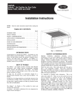
WHEN END CUTTING ON WORKPIECES 4" WIDE
OR LESS, CLAMP AND HOLD AND FEED THE
WORKPIECE WITH THE PUSH BLOCK USING
BOTH HANDS AS SHOWN IN FIG, #25. KEEP
FINGERS CLEAR OF BIT WHEN MOVING WORK
PIECE ACROSS THE CUTTING AREA.
12. ROUTER BITS ARE EXTREMELY SHARP,
Be exlra carefu; when working around them,
13. SOME ROUTERS WHEN USED IN AN UPSIDE
DOWN POSITION SUCH AS ON A ROUTER
TABLE WILL FALL (OR DROP) OUT OF THE
ROUTER BASE WHEN THE BASE CLAMP IS
LOOSENED, IT IS THEREFORE ABSOLUTELY
NECESSARY TO SUPPORT THE ROUTER
MOTOR FORM BELOW WHEN THE BASE
CLAMP IS LOOSENED TO MAKE ADJUST
MENTS, OR FOR ANY OTHER REASON.
14. ALWAYS LOOK UNDER THE TABLE AT THE
SWITCH WHEN TURNING THE ROUTER ON/OFF
AND TOUCH NOTHING BUT THE SWITCH.
NEVER REACH UNDER THE TABLEWHEN
ROUTER IS RUNNING FOR ANY OTHER
REASON.
NOTE: it is far safer and convenient to use a "Sears
Craftsman 925C60 Router Table Switch
Package". This switch provides a key
operated ON/OFF button WhiCh allows very
fast and easy access when and if it becomes
necessary to turf, the router "OFF" quicldy.
The key can be removed to render the
switcM inoperable to unauthorized people.
NEVER PUT YOUR FINGERS UNDER THE
GUARD WHEN THE ROUTER IS PLUGGED IN.
15. ONCE GUARD IS INSTALLED
FOR ROUTING,
DO NOT REMOVE
FOR ANY REASON.
ALWAYS USE THE ROUTER TABLE FENCE
TO GUIDE THE WORK. DO NOT WORK
FREEHAND.
16. MOUNT ROUTER TABLE FIRMLY AND SECURELY TO A WORK SURFACE BEFORE USE.
FAILURE TO DO SO COULD CAUSE TABLE TO
TIP OVER OR SLIDE DURING OPERATION
RESULTING tN PROPERTY DAMAGE AND/OR
SERIOUS BODILY INJURY,
When using the pilot type bits, keep the fences as
close to the pilot aspossible to provide additional
backup' and additional guidance and to avoid "
chances of an accident and possible personal
injury.
=
11.
BEFORE MAKING ANY CUT, UNPLUG ROUTER
AND MAKE ABSOLUTELY SURE THAT THE
GUARD CLEARS THE ROUTER BIT AND IS
FUNCTIONING NORMALLY.
ALWAYS USE THE STARTING PIN AND
PILOTED BITS FOR FREE HAND ROUTING
IRREGULAR SHAPED WORKPIECES.
10, ALWAYS
FEED AGAINST THE ROTATION
THE CUTTER
WHEN ROUTING
ON THE
ROUTER
TABLE,
17. WARNING
OF
18. WARNING:
ROUTER VIBRATIONS SOMET;MES CAN
CAUSE FASTENERS FOR THE TABLE, THE -:
ROUTER AND THE UNITI2ED FENCE TO GET
LOOSEI PERIODICALLY CHECK FASTENERS
TO MAKE SURE THEY ARE TIGHT AND
SECURE.
INTRODUCTION
How otlen have you needea a large guiclingsurface on a
muter table? Your Sears Craftsman Industrial Router
Table wilh Unitized Fence comes with:
a. A unique 4" high unitized fence designed to
assist end grain routing for making tenons,
sliding dovetails and tongue and groove joims
along with most edge and lace culling operations.
b. A specially designed pusM block witM quick clamp for
back up and clamp;rig boards up to 4" wictthfor end
grain routing.
c. An accurate and quick adjusting jointing fence adjustable to proper jointing depth of cut.
d. A unitized lence designed to enable routing operations like grooving; Iluting; veining: crown molding etc.
up to 2 V2"away lrom the edge toward the middle of
the board.
UNPACKING
e, Dust collecting attachment for most shop vac hook
ups.
To increase the work surface of your muter table, "Sears
Craftsman 925212 Industrial Roular Table Extensions"
are available as an optional produ= from Sears,
In order to simplify handling and minimize any damage
that might occur during shipment, your new rouler table
is packaged unassembled. We know you are anxious to
see w_al your new tool will do, but a few minutes spent
now carefully reading the following instructions, will
result in less frustration and more enjoyable operation
later.
Start by checking and accounting for all the loose paMs.
If any parrs are missing, contact your local Sears retail or
catalog outlet for replacement.
AND CHECKING
CONTENTS
WARNING: YOU MUST READ AND UNDERSTAND
ALL THE INSTRUCTIONS COMPLETELY BEFORE
ATTEMPTING TO ASSEMBLE AND OPERATE YOUR
ROUTER AND ROUTER TABLE.
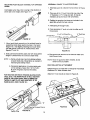
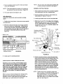
ASSEMBLY
ASSEMBLY OF TABLE
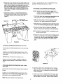
1. Turn _he table upside clown.
2. Place one of the table legs al one end of the table as
shown in Figure 1.
3. Insert the #10-32 x %truss heacl screws through the
table lop and leg. Six are required for each leg.
FIGURE 1.
screw. The lock washers should be against the
inside ol the leg.
four #10--32 stop nuts 1o secure the throat plate to
the table, as shown in Figure 5. Tighten securely.
5. Repeat for the remaining leg.
8. Turn the table righl side up and tighten all 12 screws
and nuls with a wrench or pliers.
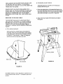
ASSEMBLY OF THROAT PLATE TO TABLE
1. Assernl31e four #10-32 x % panhead screws and four
#10-32 stop nuts to table as shown in Figure 2,
NOTE: After a low turns of the screw, resistance of
further turning wilt be experienced---this is
normal. Do not tighten completely: just enough
so screws protrude through nut.
#10-32 Stop nut
FIGURE 5.
Top of Talkie
#I 0-32 Stop
MOUNTING ROUTER TO TABLE
ALWAYS UNPLUG ROUTER BEFORE MOUNTING
(The table is designed to accept most Sears Craftsman
Routers. However, i1 will accommodate other brancls
with bases up to 7" in diameter by properly aligning,
drilling and countersinking the required mounting holes
into the thrcat plate).
#10-32 x % Panhead
Screw
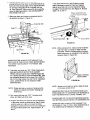
ATTACHING SEARS ROUTERS WITH THREE HOLE
BASE PLATES
2. Place the throat plate into 1he large opemng in the
table. The position of three small holes must be as
shown in Figure 3.
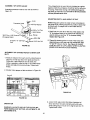
1. Remove the router base plate (back plate) from the
router, and put base plate an_ screws in a convenient
place for storage.
Three Small
Holes
Large Hole
2. While holding the router upside down, position il to the
underside of the throat plate, as shown in Figure 6,
L
oOo__o.0oo _
LJ.__ uF-IOEOEOE
FIGURE 3.
3. While pressing sown on the lhroal plate, gradually
turn the screws inward or outward until the throat
plale is level with the taOle lop. Throat plate must be
; stable; thai is, it musl rest on all lout screws and not
"rock" when pressure is al:_lied. Refer to Flours .4.
I
f
i
[
Throat Plate
" ......... "
FIGURE 4.
.
'
FIGURE 6.
3.RotatetherouteruntilthethreemountingI'_oles
inthe
In st_p 4, use the three _/'_s-18x !" long flathead screws
provided. These screws are black in color.
router base lineup with three af4he holes in the throat
plate. (It will be helpful il you orient the router such
Ihat you can easily reach the ONIOFF switch from the
front of the table. Sears Craftsman 925090 Router
Table Switch Package provides easy access to ON/
OFF button).
ATTACHING OTHER BRANDS OF REUTERS
NOTE: Reuters having a total overall height of 13 .
inches or less and a base diameter of 7 inches
or less can be accommodated.
4, Insert three #10-32 x =t6"long flat head machine
screws (provided) through holes in the throat plate
and tighten securely, into the router base. See
Figure 7,
1.11 the throal plate I_as already been assembled to the
table, remove it, IF NOT, proceed wilh step 2.
#10-32 x 3/€
Flat Head Screws
Table Top
2. Place the throe1 plate on a flat surface so that the
locations of the holes are shown as in Figure 3.
3. Place the router upside down next to the throat plate
so that the handles are aligned as shown in Figure 8.
4. Remove the base from the rouler, set aside the
screws, and place the base plate on the lhroat plate.
NOTE: DO NOT FLIP OR ROTATE THE BASE PLATE
WHEN DOING THIS.
5. Posilion the base plate so the hole in the base plata is
centere_ with the hole in the throat plate. It may be
necessary to relate the base plate slightly so Ihal no
hole in the plate line-ups with a hole in 1he throat
plate•
\
Router
Tab!e Front
FIGURE 7.
ATTACHING SEARS ROUTER MODEL NO. 27504
Proceed as with three hole base elate reuters exceot; as
in =.tap _, line uptrie lout:large threacted holes in the
router base with the four la.ri3e counler_unk
hi31_s in lh_
ith£oat.platel
NOTE: Router will
lin_.e
up in one position on.ly.
i
In step 4, use the four large 1" long (MS x 25 Metric)
flathead screws provided. These screws are silvery in
color.
i';.
" :FIGURE 8.
ATTACHING SEARS ROUTER MODEL NOS, 27505
AND 27506
Proceed_as
_follows:
with three hole base plate touters
6, Mark the-positionOf tile. mounting holes On the base
plate with a pencil or felt tip marker. That is, the base
plate is being used as a temp!ate to locale the holes
on the lhroal plate.
exoeptas
!n step & !!ne-up me three t arge;threa_ec! holes in the
r.o_ter haae.wi.tl3 the,three,correspond ng lare countersunk holes in the throat plate lhat rnalch.
7. Select a drill bll with a diameter that is the same as or
slightly Digger than the head of the screw which.held
the base plate on the router. (Reler to Step 4 above.)"
NOTE: Router will lineup in one position only.
_S
NOTE: It l_e head of the screw is "V-shaped"
be countersinking.
you wltl
ff the head of the screw is net "V-shaped" you
will be counterboring
8. Countersink or counterbore holes into the throat
plate to a depth so the heads of the screws are
slightly below the top surface of the throat plate.
9. Now select a drill bit with a diameter thai is lhe same
as or slightly bigger than the threads on the screws.
Drill holes through the throat plate at the previously
countersunk or counterbored holes. Use care so drill
goes through the centers of these holes.
With lhe desired bit in the ,'outer, select a throat plate
insert with a center h01e slightly larger than the diameter
of the router bit, NOTE: For bits 1- =/_" diameler and
larger, do nol use an Insert.
WARNING:
than 2".
Do not use bits having diameters larger
The throat plate inserts are designed to be snapped into
tr_e throat plate. Slide the large tang under the edge of
the large hole in the throat piate as shown in Figure 9.
Using your thumb, press down on the insert until the
small tang snaps into position.
10. Assemble the throat plate to the table as described
in a previous section.
11. Assemble the router to the throat plate as described above using the screws thai held the
base plata to the router. Put the base plate in a
convenient location for storage.
SELECTING
INSERTS
AND INSTALLING
To remove the insed, place the point of a small screwdriver into the slot (with the small tang) and pry the insert
out of the throat plate.
THROAT PLATE
Use Screwdriver to
Remove Table Insert
Use thumb pressure to
snap table inserl imo
positbn
\
(
FIGURE 9,
Throat plate
inserl
ASSEMBLY
OF UNITIZED
WARNING: BEFORE ASSEMBLING AND AT'rACI_.
ING UNITIZED FENCE TO TABLEs MAKE SURE THAT
ROUTER IS UNPLUGGED AND THE BIT IS BELOW
THE TOP SURFACE OF THE TABLE.
ASSEMBLY OF JOINTING FENCE TO UNITIZED
FENCE
1. Slide joinling fence through rectangular opening in the
cavity, provided on the unitized fence (V-guide on the
unit_.ed fence will slide in the V-guide on the under
side of jointing fence). See Figure 10.
FENCE
You will observe as you face the front of the lab_e, that
on the right side of the table top there are two round
holes approximately =/=" in diameter, and on the left
side, tha_a is a 4" long slol. These are used to attach the
fence to the table,
For all edge cutting and end cutting operations, attach
fence using the front hole and the slot. See Figures 11
and 12 for available fence adjustment on either side of
the muter bit center.
2. Insert 1/,-20 x 1" long hex head bott through Ihe
hole in the unilized fence (from the underside) and the
slot in the jointing fence.
3. While holding the head of the boil in the hex recess
on the underside of unitized fence, place a flat washer
over the bolt and screw small %-20 knob on bolt.
When knob is loosened, the jointlng fence can slide back
and forth in the cavity for proper jointing adjustment.
FIGURE 11.
FIGURE 10.
ATTACHMENT
TABLE
OF UNITIZED FENCE ASSEMBLY TO
ALWAYS UNPLUG ROUTER BEFORE ATTACHING
FENCE TO OR REMOVING tT FROM TABLE,
Farallroutingoperations
away
from edge on the unaerside of workpiece, suctl as Gn3oving, Fluting, Veining,
Crown Molding, etc., at!act1f:ence using back hole and
the slot. See Figures 13 and 14 for avaitable fence
adjustment from the router bit center.
IJepenamg upon Ine roulsng operalton, insert one ol
the "2-20 x 1_/4'' long carnage belts through one ot
the holes on the right side o! the of the table top (from
the underside) and the short slot in the fence. Make
sure square ol belt Fr_sinto square recess in table.
2.
,
While hotding the bolt in place, install a _!:_"I.D. flat
washer and a large 1/,-20 knob onto the belt to
loosely secure the fence to the table.
4. Repeat Steps 2 and 3 for table slot and fence slot on
lhe left side of the table.
ASSEMBLY OF PUSH BLOCK
Screw the small end of clamp rod into threaded hole
in clamp plate until the plate bottoms on it's shoulder
(make sure clamp is oriented such that letter "(3" is
facing outwards as shown in Figure 16.
1,
FIGURE 13,
.
,
Tightly secure clamp plate to clamp rod using V4"
helical lock washer and a hex nut.
Insert the opposite threaded end of clamp rod
lhrough hole in push block arid install a flat washer
and a wing nut onto it. (Refer to Figure 16.)
21/2
FIGURE 14.
1. Assemble unitized fence assembly to table as shown
in Figure !5.
1/,¢Helical Lock Washer
5/i,a"Flat
end
Washer
Push Block
Cramp Rod
Clamp Plate
FIGURE
16.
WARNING; ROUTER VIBRATIONS SOMETIMES CAN
CAUSE V4-28 HEX NUT AND CLAMP PLATE TO GET
LOOSEt PERIODICALLY CHECK FASTENERS AND
CLAMP PLATE TO MAKE SURE THEY ARE TIGHT
AND SECURE.
\
'Figure iS
MOUNTING
FENCE
PUSH
BLOCK
ASSEMBLY
ASSEMBLY GUARD TO UNITIZED FENCE
ON UNITIZED
1. Assemble guard to unilized fence as shown in Fiqure
19.
Clamp plate when free, Ides to swing in the direction of
arrow due to _'s weight. (See Figure 17.)
2. Press one of Ihe lh" push nuts onto one end of the
lk" Diameter x 2 "he' long pivot pin. (It may be
necessary to tap il onto pin with a hammer).
3. Position the guard on the fence so the holes in the
guard line up with the hole in fence.
4, Insert pivot pin through holes.
5. Press remaining 1/,. push nut onto the other end of
the pivot pin.
1!4"x 2"/_# Pivot Pin-..-_
1/4"Push NLI__
1!4'Push Nut
] I
FIGURE 17,
.
Mount push block assembly on the unitized fence by
supporting clamp plate against the face of the lence
(Figure lB. ) and aligning retaining rib on push block
with tl_ groove in the lace of unlti:,e_ fence. (See
Figures 17 and lB.)
FIGURE 19.
2. Slide push block assembly back and forth along entire
length of unitized fence to see that it slides freely.
6. Pivct guard back and forth a few times to make sure
that it moves freely.
NOTE: a. Remove dust and chips from sliding surfaces
of push block and unitized fence as needed to
maintain good stidingmotion.
NOTE: Once the guard has been {nstalled, do not
remove it for any reason.
DUST COLLECTING ATTACHMENT
h.
Occasional application of furniture spray wax
on the sliding surfaces ONLY of 1he PUSH
BLOCK will greatly improve the sliding
motion.
Unitized fence is provided with a hookup for most Sears
Craftsman 21Iz"hose diameter vacs.
Attach 21/z'' hose nozzle as shown in Figure 20.
FOR ROUTING ON ENDS (TENONS, SLIDING DOVETAILS, ETC.) THE WORKPIECE IS HELD AGAINST
FACE OF UNITIZED FENCE AND CLAMPED BETWEEN CLAMP PLATE AND SURFACE "S" OF
PUSH BLOCK. (SEE FIGURE 18.)
Surfaces
"S"
of Unitized Fence
FIGURE
ClampPlate
18,
1,0
NOTE: OPERATING ROUTER TABLE WITHOUT USE
OF WETJDRY VAC MAY RtS_SULT IN EXCESSIVE
COLLECTION OF SAWDUST AND CHIPS UNDER THE
FENCE AND THE GUARD.
B. TO SEARS LEG SET #22235
REMOVE DUST AND CHIPS FROM UNDER Title
GUARD AND THE FENCE AS NEEDED TO MAINTAIN
GUARD AND FENCE FUNCTION. MAKE SURE THE
ROUTER IS TURNED OFF AND THE BIT IS NOT
ROTATING WHEN DOING THIS. KEEP WORK AREA
CLEAN.
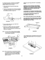
1. Place the router lable on the assembled leg set wilh
the muter table base flush with the front of the leg set,
The holes in the base of the muter table should align
with holes in the leg set as shown in figure 22.
MOUNTING THE ROUTER TABLE
2. Secure the router table with hardware provided in
the leg set.
Assemble lag set as directed by the inslructions
included with the leg set.
THE ROUTER TABLE MUST ALWAYS BE FIRMLY
AND SECURELY MOUNTED TO A WORK SURFACE
BEFORE USE. FAILURE TO DO SO COULD CAUSE
TABLE TO TIP OVER OR SLIDE RESULTING IN
PROPERTY DAMAGE ANDIOR SERIOUS PERSONAL
INJU RY.
A. TO A WORK SURFACE
Each leg has three slotted holes at the bottom for
mounting. Firmly secure router table to work surface,
using appropriate lasleners (not provided) as shown
in Figure 21. The stots are V4" wide x %" long and
will accommodate screw sizes up to #'12.
Table Leg
FIGURE 22.
Work Surface
O
!
FIGURE 21.
For added versatility, secure tho tabl_ -to a piece of V=';or
thicker plywood which can- be "C" clamped to your work
surface:
11
ASSEMBLY OF MITER GAUGE-"
The unitized fence on your table is providecl as a guide
against which the workpiece should be held for accurac'y
in routing. Free hand routing (not holding work_againsl
the fence) is hazardous and should be strictly avoided
without piloted muter blts.
Assemble prolractor head to miter bar as shown in
Figure 23.
ADJUSTING DEPTH AND HEIGHT OF CUT
Knob
Protractor Head
Rolate the guard upward in order to have lull access to
the router bit for making adjustments; select a board that
is smoeth with it's edges true to each other and it's
surfaces and:
_"
.O4--#10
yh
_
Fie! Wasiqer
#10-32 x _h¢ Pan
.
v_.," Hea_ Screw
3/16" Die. x 5/8' Groove€
I _
Pointer
Pin (assembled)
Mitre Bar
i
.
#10-24 x 3/_,,Carriage-.._
Bolt
_ _t_--#10.32 Hex Nut
FIGURE 23.
ALIGNMENT
SLOT
Mark lines "A" and "B" on the end ol this board. Line
"A" for desired depth of cut (amount of material you
want to remove) and line "B" for desired cutUng
height. See Figure 25,
Clamp this board against the face of the fence with
edge resting on table top and end marked with lines
"A" and "B" close to the bit. See Figure 25, (MAKE
SURE ROUTER IS UNPLUGGED WHEN CLAMPING
BOARD AND MAKING ADJUSTMENTS).
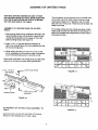
OF UNITIZED FENCE TO MITER BAR
1. Measure distance from each end of unitized fence to
edge "E" of miter bar slot on the table as shown in
Figure 24. If both distances are the same, the
fence is parallel to miter bar slot. If not, loosen large
knobs and adjust fence accordingly. Tighten both
knobs.
2. Position miter gauge on fable as shown in Figure 24.
Edge E
....,
--
,,£....
--
"-'_Z_le
_JI
!_"
•
-
\
_;'_
FIGURE 25.
-IC3D
FIGURF 24.
3. Loosen bolh larg_ knobs that allow movement of
fence and move forward and backward until outermost cutting edge of router bit is aligned with line "A",
Tighlen both knobs.
OPERATION
WARNING: ALWAYS UNPLUG THE ROUTER BEFORE MAKING ANY SETTING, ADJUSTMENTS, OR
CHANGING BITS.
12
of bil is aligned with line "B". (Refer to you-t-muter's
owner's manual !or adjusting your router properly).
AFTER MAKING THIS ADJUSTMENT, BE SURE
ROUTER IS SECURELY TIGHTENED IN THE
ROUTER BASE, THE BIT IS SECURELY TIGHTENED
IN THE ROUTER CHUCK, AND ROUTER BASE IS
TIGHTLY SECURED TO TABLE TOP.
f
----'_
Feed workpiece in-_I
direction
of arrow "]
5. Remove the 13oardfrom the lence and lower the
guard to operating position.
Jo',ntin Fence
WARNING: DO NOT OPERATE ROUTER IF ANY
PART OF THE BIT CONTACTS THE GUARD.
Guard not shown for
reasons of ctadty
FIGU RE 26.
NOTE: Workpiece to be routed could be substituted for,
with scrap board when making adjustment.
6. Repeat the test cut on the scrap wood with guard
down.
USING ROUTER TABLE AS JOINTER (FULL EDGE
CUTTING)
7, The router table is now ready for use.
For maximum strength and accuracy, boards to be
jointed together should be smooth and true. The edges
should be true 1o the workpiece surface. You can true
the edges on your router table using a straight bit.
1. Check to see if face of jointing fence is fluslq wilh the
face of unitized fence. If not, loosen small knob on
jointing fence and adjust. Tighten knob on jointing
fence.
NOTE: The jointing fence provides a continuous support
for the workpiece, as it is fed beyond the router
bit. It compensates for the gap created by the
removal of material by the router bit.
2. _Adju.stdeplh o1'cut (material you wa_Ttq remove) and
,router biFheight as described previously for Figure 2,5.
_ghl!y secure the fenc_ and the router as described
:before. (MAKE SURE ROUTER IS UNPLUGGED
:WHI_N MAKING ADJUSTMENTS)4_
_
3. Lower guard to operating position.
NOTE: For best jointing results, take very shallow cuts:
'/=="or tess.
USING ROUTER TABLE FOR EDGE CU'I'i'ING-with non-piloted bits:
1. Position the jointing fence such that it's face is flush
with the face of unitized fence Tighten small knob on
jointing fence. See Figure 27.
[-- Dep_ of cut
. .
__
f__- ...................
0 i ,----_I(_
I IIk, _I
__...,..
_
:-...,__....-,-,--._.--_
,
......
_--...+
:I _ .
-_ ...
_, --...
_]
I !i qlCCI
IC]C]
o°o
,,o, o,oo0
..]!
I .jl _
_l---qr-q'r-'T'--I
dire_ion of arrow ]'
....
. _
- --'---'_--'w
"i
Guard not shown for
reasons of clarity
FIGURE 27,
4_._Checkyour adjustments by turning the muter ,ON"
and feedir]g.a piece of scrap woe_a low inches
beyond fog!Or bit. Then slop and turn router "OFF"
NOT.E: Feed work against the rotationol the cutter (in
the direction shown byarow in Figu_e 26].
5o Lo0_en knob on,jeinting fence arid move it out, flush
against !be finished edge ;o'tscrap .w,ood. Retigl!ten
the 't_hOb'_i
See Fiaure 26.
8, Adjust depthpf cut (material you want toremove) &nd
router bit heighl as described be!ore. Tighten both
large,knobs lqloclf fence on table. Tightly secure ,the
r_Ju,tei.(MAK_Su_E
RCUTER IS UNPLUGGED
,'
WHEN MAKING ADJUSTMENTS).
3. Lo_,e[ guard to opera'dag :posilion.
4. Test cut a piece of scrap wood:to make sure adjust
menls are satistaclory.
NOTE: The push block, and clamp plate asser_bly will
not accommodate workpieces wider _han 4",
NOTE:
EXAMPLE: CUTTING TENONS
Feed work against the rotation of 1he cutter (in
the direction shown by the arrow in Figure 27),
1, Make ¢erlain thai jointing fence is locked inposition
with its lace flush with that ol unitized fence. '
5. The router table is now ready for use.
2. Mount push block assembly on unitized fence as
shown before in Figures 17 and 18.
with piloted bits:
When bits withpilots are used to control the cutting
depth:
3. Install proper table inserl into the throat plate hole,
,
1. Position Ihe jointing fence in the same manner as with
non-piloted bits.
2. Move the unitized fence back only enough to permit
the pilot lo control the cutting depth. Positioning the
unitized fence as close to the pilot as possible will
serve as abakcup and will help to prevent chances of
an accident, and possible personal injury, See
Figure 28.
-Depth
Mark lines "A" and "B" on the edge of the workpiece
close to the end to be cut. Line "A"foR FULL DEPTH
OF CUT (total amount of material you want to re
move) and line "B" for FULL DESIRED HEIGHT OF
TENON. See Figure 29
Clamp Plate
Workpiece side flush
against face of unitized
lence
Line B
Wing Nut
of cut
Line A
Top culting edge
...............
-_:_htl ......
/
..................
........
q
.
Face of fence
.........
Push block
LJL F-lrqDlll ooo.o,,o,ooo,o
J J_"
IF--q[-]]:
-
Guard not shown for
reasons of clarity
Outermosl
culling edge
J:direction of arrow
Throat
plate
FIGURE 28.
Edge of throat hole
Max.widlh
FIGURE 29.
3. Lower guard to operating posilion.
,
USING ROUTER TABLE FOR END CUTTING
WARNING: END CUTTING IS PERFORMED WITH
THE GUARD ROTATED BACK SO THAT IT DOES
NOT COVER THE BIT. THEREFORE, EXTREME
CARE MUST BE TAKEN WHEN END CUTTING, SO
THAT YOUR FINGERS, HANDS, OR ANY OTHER
PART OF YOUR BODY DOES NOT CONTACT THE
BIT WHICH CAN RESULT IN SERIOUS BODILY
INJURY.
t
When routing on end_, of workpiece Ior making tenons,
sliding dovetail.s and tongueand groove joints, lhe
workpiece musl be made smooth with beth edges and
ends made true to each olher and its surfaces.
Position workpiece between clamp plate and push
block so that Its side is hetcl flush against face of the
unitized fence, the end !o be cut is resting on the
edge of the throat plats hole and edge marked with
lines "A" and "B" is facing ro_er bit. Clamp work
piece in this position by snugly tightening the wing
nut on clamp rod while making sure that clamp plate
stays oriented on workpiece, as shown in Figure 29.
MAKE SURE ROUTER IS UNPLUGGED WHEN
POSITIONING AND CLAMPING WORKPIECE AND
MAK!NG ADJUSTMENTS,
NOTE: Tighten wing nut just enough to clamp work
piece in posilion. OVERTIGHTENING wing null
could cause binding in the sliding motion of
push block, which in turn may result in variations and!or steps in the finished tenon surface
when cut. See Figure 32.
4"
k
in the same manner as in step 5 above, except
edge of workpiece sl_ould be held flush against
face of fence and end to be cut should be resting
on edge of throat plate hole. See Figure 31. Repeat
steps 7, 8, 9, and 1 0.
unitized fence and the muter as described before so
that outer most curling edge of bit is aligned witll Ilne
"A" and top cutting edge ol bit Is aligned with llne
"B". See Figure 29. Tightly secure the fence and the
router as describea belore in ADJUSTING DEPTH
AND HEIGHT OF CUT.
Edge workpiece flush
__. agains_ face of unitized
7. Slide push block and therefore workpiece back to
the position as shown in Figure 30.
ence
3poeite side
Edge "E"
_E
Throat Plate Insert
_
End of tenon
FIGURE 31.
NOTE: When cutting tenons, always clamp workpiece
with end to be cut resting on edge of throat
plate hole. This will minimize steps in finished
tenon surtace due lo variations in the table top
Ilatness. (Refer tc Figure 32.)
WHEN ROUTING, ALWAYS FEED AGAINST THE
ROTATION OF THE CU'Fi'ER. FEED WORKPIECE
THE DIRECTION SHOWN BY THE ARROW. SEE
FIGURE 24.
IN
8. Turn router and shop vac "ON". While holding push
-._..block and GUIDING WORKPIECE AGAINST
FENCE with both hands and FINGERS (Figure 30)
AT A SAFE DISTANCE FROM SPINNING BIT, feed
the work,piece across tile bit to make FULL DEPTH
OF CUT IN ONE PASS. (DO NOT STOP FEEDING
UNTIL WORKPIECE IN FAR ENOUGH PAST
SPINNING BIT).
1/ [ ! _)/('/ i 1_
NOTE: Always cut full depth on all four sides of tenon
in one pass across the bit.
NOTE: Clamp and test cut a piece of scrap wood to
check your adjustments belore making your
finished cut.
USING ROUTER TABLE FOR OPERATIONS AWAY
FROM EDGE ON THE UNDERSIDE OF WORKPIECE
SUCH AS GROOVING, FLUTING, VEINING, ETC.
9. T_m muter and shop vac "OFF". Unclamp work
piece, and slide push 131oc_back.
10. Position and clamp the opposite side of workpiece
in t_e same manner as described in Step 5 (make
sure"the wing nut is tight just enougtl to clamp
workp=ece in position and end to be cut is resting on
the edge o! throat plate hole). Repeat steps 7, 8,
and 9.
'" Steps in finished
ALWAYS UNPLUG THE ROUTER BEFORE MAKING
ANY SETTING, ADJUSTMENTS, OR CHANGING BITS
WHEN ROUTING, At.WAYS FEED AGAINST THE
ROTATION CF THE CUTTER. FEED WORKPIECE IN
THE DIRECTION OF ARROW !N FIGURE 34.
15
.
USING ROUTER TABLE WITHOUT THE UNITIZED
FENCE
For maximum accuracy, one edge of your workpiece
(edge sliding againsl the fence)-rhust be true and
slraight. Set up your fence as follows:
WARNING: ROUTING WITHOUT THE UNITIZED
FENCE AND THUS THE GUARD COULD CAUSE
ACCIDENTS AND POSSIBLE PERSONAL INJURY,
EXTREME CARE MUST BE TAKEN FOR THIS .*
ROUTING OPERATION,
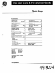
1. Raise guard and rest it against the back o! the
vacuum outlet.
2. Position the fence behind tile rouler bit for the desired
cutting depth (the distance of the cut from the edge of
Ihe workpiece, as shown in Figure 33).
ALWAYS UNPLUG THE ROUTER BEFORE MAKING
ANY SETTING ADJUSTMENTS, OR CHANGING BITS.
ALWAY@ FEED WORKPIECE AGAINST THE
ROTATION OF THE CUTTER.
ONLY PILOTED ROUTER BITS ARE TO BE USED,
MANY ROUTING APPLICATIONS (SUCH AS SHOWN
IN FIGURE 35) WILL REQUIRE THE FENCE TO BE
REMOVED FROM THE TABLE.
I
Router Cut
3. Securely tighten both knobs and LOWER THE
GUARD OVER THE BIT.
4. Make the cut by sliding straight edge of workpiece
against the fence. Use a push stick as shown in
Figure 34. [For each successive cut, the fence would
need to be re-adjusted).
NOTE:
Door
FIGURE 35
Test cut a piece of scrapwood before making
your finish cut. Feed workpiece in the direction
of arrow (Refer to Figure 34).
If the workpiece I_eing cut is between _e cutter and the
operator, then feecl from RIGHT TO LEFT as shown in
Figure 36.
i
FIGURE 34
NOTE: When routing deep cuts (conlro_ed by router bit}
in a workpiece, remove material in increments to
prevent your muter from overloading. Repeat
operation wilh several passes until the desired
deplh is achieved.
FIGURE 36
16
II
I1t1:1%.4..ILLI;Jt
I,,'_
_IIVI;Illl
!.1111;I
L.II_.II;;II.II,._/I
I0.,
I_.I
l_l_.-J
.-_s|_t,,.'_
being cut, then feed from LEFT TO RIGHT as stlown in
Figure 37.
away from the _arting pin, as shown by position #3 i_
Figure 39.
6. At this point, the piloted router bit is acting as a guide
and not the slatting pin. Feed the workplace against
' the rotatior, of cutter unlil the complete edge of the
workpiece has been cut. Then slide workplace away
Irom cutter.
Starting Pin
/
Workpiece
Position #3
Position #2
FIGURE 37
FREE ROUTING IRREGULARLY
PIECES
K @SDSC3EIN
SHAPED WORK
CZtl " II IIZ E]IZ EZ i
FIGURE 39
For routing irregularly shaped work pieces, a starting pin
is provided. The starting pin is used for "free-routing"
witl_ piloted bits only, It Is not used for any other
operation described In this manual.
PROTRACTOR
' 1 Remove the fence from the table.
Your protractor will sorve as a handy aid when extra suppo
is needed for routing sma!l workpieces or e_s o1'large
workpieces. See Figure 40.
2. Thread starting pin into tapped hole in the throat
plate, as shown in Figure 38, and tighten securely.
3. To free route with starting pin, orient workpiece on
table top against starting pin, as shown by position #1
in Figure 38. Workplace sl_ould not contact cutter.
Fence
4. Gradually swing workplace contacting pilot, swing
workpiece against tt_e cutter unti1111o
complete edge
of the work piece has been cut. Then slide workpieca.
away from cutter.
worl,; piece
Position #2
B_
Starting J°in
Position #1
Protractor
/
Workpiece
/
/
Figure 40
NOTE:, FOR ALL ROUTING OPERATIONS REQUIRING USE OF,MITER GALIGE ALONG WITH
THE EENCE, BE SURE TO ALIGN FENCE
_,_ITH MITER 'BAR SLOT-BEFORE MAKING
ANy :CUTS. SEE FIGURE 24.
17
Notes
18
4O
35
13
18
6
5
3.,_1
3O
o
I I Ij,25
• ._:=
_,19
25
I
3
24
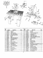
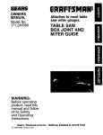
Key
NO.
Part No.
I
2gLCN-753
2
Descdpllon
Key
No.
Quan.
Part No.
Descrtptlt]n
Quan.
RouterTable
t
_
21_.-651
Clamp F_od
1
29LCN-755
Table leg
2
23
29L-652
Clamp Pl_,_e
1
3
29A-306-14
3/4OD x 913210Washer
3
24
29A-246-12
1t4-20x I Ig Hex Head Cap Screw
1
4
2gA-310-7
1/4-20 x I-3,/4 Ig CarnageBolt
2
25
29GD-321
1/4 Washer Cap Push Nut
2
5
29A-242-12
110-32 I"k]xMachine $clew Nul
13
26
29A-252-B
5/16-18 Wing Nu_
1
6
31L.559
_ter Bar
1
27_
29A-306-27
11/160D x 111321DWasher
1
Pointer
I
28,
29LCN-763
!10-32 x 518Ig Smoo_ Truss Head Screw
12
/10-32 x ,_16 Ig PanheadScrew
I
•
7
j,
-
8
2gA-264-B
29'.
29A-327-3
1/4 HelicalLockwasher
I
9
29L-I&.3
3/1600 x 5i81O Groo_ Pin
I
30
2gL-66_
_no'b
2
I0
29L-293
ProlractorHead
1
31 "
29L..659
Knob
I
11
31L-560
Kno_
1
32
45A-322
Label (RoulerTable)
1
12
2gLC_1-781
Plaslic Insarl Washer
6
33
4SA-323
Warning Label (Fence)
!
13
2a_A-2gB-t3
110-32 x 318 Ig FlalhezdScrew
3
45A-_24
I._bel (Fence)
1
14
29A-sog-t
#10 L._.,_Washer
12
35
26LCN-?fi2
M8 X 25 (Metric) Ral C'Sunk HD Screw _,,_' / _,_'
15
29A-306-15
1i20D x 3/161!3Washer
1
36
29A-242-8
t14-28 Hex Machine Screw Nut
1
16
20A-310-5
#10.24 x 3J4 Ig CarnaoeBolt
1
37
291.CN-756
Throat Plate
1
17
29LCNo754
Fence
1
38
29P-84-13
Slart_
18
' 29LCN-7_0
Guard(Ovemead)
1
39
29LD-123-2
11Q-32 Hex Slap Nut (ESNA)
10
2gLCN-TS7
O_erhead Guard PivolPin
1
40
29A-298-!
#10-32 x 5/8 Io FlalheadScrew
20
_29LCN-758
_djusl,l_le Fenc_
1
41
29A-264-7
#I0-32 x S/8 Paflhead Screw
2e3LCN-7S9
P_sh _:ock .....
1
42
49LCN-39
Ins_.'uc_ionManual
2"I
LL
1 g.
1
Pin (7/16" Pilol)
8
4
-
4