1
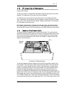
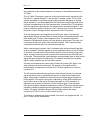
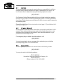
©2003 Crown Broadcast, a division of International Radio and Electronics, Inc.
25166 Leer Drive, Elkhart, Indiana, 46514-5425 U.S.A.
(574) 262-8900
Rev. 1.0
Revision
Print Date
Rev. 1.0
January 2003
©2002, International Radio and Electronics, Inc.
Portions of this document were originally copyrighted by Michael P. Axman in 1991.
All rights reserved. No part of this publication may be reproduced, transmitted,
transcribed, stored in a retrieval system, or translated into any language in any form
by any means without the written permission of International Radio and
Electronics, Inc.
Printed in U.S.A.
Sony and RCA are trademarks of their respective companies.
IREC attempts to provide information that is accurate, complete, and useful. Should
you find inadequacies in the text, please send your comments to the following
address:
ii
FMX30/FMX100/FMX250 User’s Manual
Rev. 1.0
Table of Contents
Table of Contents iii
Section 1—Getting Acquainted
1.1 Your Transmitter .........................................................................................1-2
1.2 Applications and Options.............................................................................1-3
1.2.1 Stand-Alone.............................................................................................1-4
1.2.2 Backup ....................................................................................................1-4
1.2.3 Booster....................................................................................................1-4
1.2.4 Exciter .....................................................................................................1-4
1.2.5 Translator ................................................................................................1-5
1.2.6 Satellator .................................................................................................1-6
1.2.7 Nearcasting .............................................................................................1-6
1.3 Transmitter/Exciter Specifications ...............................................................1-7
1.4 Receiver Specifications................................................................................1-9
1.5 Safety Considerations ................................................................................1-10
1.5.1 Dangers.................................................................................................1-10
1.5.2 Warnings...............................................................................................1-10
1.5.3 Cautions ................................................................................................1-10
Section 2—Installation
2.1 Operating Location ......................................................................................2-2
2.2 Power Connections......................................................................................2-2
2.2.1 AC Line Voltage Setting...........................................................................2-2
2.2.2 Fuses.......................................................................................................2-4
2.3 Frequency (Channel) Selection ....................................................................2-5
2.3.1 Modulation Compensator ........................................................................2-5
2.3.2 RF Tuning Adjustments ...........................................................................2-5
2.4 Receiver Frequency Selection......................................................................2-6
2.5 RF Connections ...........................................................................................2-8
2.6 Audio Input Connections .............................................................................2-9
2.7 SCA Input Connections..............................................................................2-11
2.8 Composite Input Connection .....................................................................2-11
2.9 Audio Monitor Connections .......................................................................2-12
2.10 Pre-emphasis Selection .............................................................................2-12
2.11 Processor Bypass Option ..........................................................................2-12
2.12 Program Input Fault Time-out ...................................................................2-13
2.13 Remote I/O Connector ...............................................................................2-14
Section 3—Operation
3.1 Initial Power-up Procedures ........................................................................3-2
3.2 Controls and Display....................................................................................3-2
3.2.1 Front Panel ..............................................................................................3-2
3.2.2 DC Breaker ..............................................................................................3-4
3.3 Operating the FMX.......................................................................................3-4
iii
Rev. 1.0
3.3.1 Passwords...............................................................................................3-4
3.3.2 Main Function List...................................................................................3-4
3.3.3 Readings Function List ............................................................................3-5
3.3.4 Settings Function List..............................................................................3-6
3.3.5 Factory Setting Functions........................................................................3-7
3.3.6 Audio Monitor .........................................................................................3-7
3.3.7 Fault Log .................................................................................................3-7
3.4 Power-up procedure....................................................................................3-8
3.4.1 Apply Power ............................................................................................3-8
3.4.2 Enter Initial Settings ................................................................................3-8
3.4.3 Transmit ..................................................................................................3-8
Section 4—Principles of Operation
4.1 Block Diagram .............................................................................................4-2
4.2 Audio Processor Circuit Board.....................................................................4-3
4.2.1 Balanced Input ........................................................................................4-3
4.2.2 Audio Processor......................................................................................4-3
4.3 Stereo Generator Circuit Board....................................................................4-4
4.3.1 Low-pass filter ........................................................................................4-4
4.3.2 Stereo Generator .....................................................................................4-5
4.3.3 SCA Input................................................................................................4-5
4.3.4 Processed Audio .....................................................................................4-5
4.4 RF Exciter Circuit Board...............................................................................4-6
4.5 Digital Management System ........................................................................4-7
4.5.1 Metering Boards......................................................................................4-7
4.5.2 Front Panel ..............................................................................................4-7
4.6 Motherboard................................................................................................4-8
4.7 Voltage Regulator Circuit Board...................................................................4-8
4.8 Power Regulator Circuit Board ....................................................................4-9
4.9 RF Driver/Amplifier (FM30)..........................................................................4-9
4.10 RF Driver (FM100/FM250) ...........................................................................4-9
4.11 RF Amplifier (FM100/FM250) ......................................................................4-9
4.12 Chassis ......................................................................................................4-10
4.13 RF Output Filter & Reflectometer ...............................................................4-11
4.14 Receiver Circuit Board Option....................................................................4-11
Section 5—Service and Support
5.1 Service.........................................................................................................4-2
5.2 24–Hour Support.........................................................................................4-2
5.3 Spare Parts..................................................................................................4-2
iv
FMX30/FMX100/FMX250 User’s Manual
Rev. 1.0
I
INFORMATION
This section provides a general description of the FMX30,
FMX100, and FMX250 transmitters and introduces you to safety
conventions used within this document.
Review this material
before installing or operating the transmitter.
Getting Acquainted
1—1
I
Rev. 1.0
The FMX30, FMX100, and FMX250 are members of a family of FM stereo broadcast
transmitters. Crown transmitters are known for their integration, ease-of-use, and
reliability.
The integration is most apparent in the standard transmitter configuration which
incorporates audio processing, stereo generation, and RF amplification without
compromised signal quality. A single Crown transmitter can replace several pieces
of equipment in a traditional system.
Ease-of-use is apparent in the user-friendly front panel interface and in the
installation procedure. Simply select your operating frequency add an audio source,
attach an antenna, and connect AC or DC power and you're ready to broadcast. Of
course, the FM series of transmitters also feature more sophisticated inputs and
monitoring connections if needed.
Reliability is a Crown tradition. The first Crown transmitters were designed for
rigors of worldwide and potentially portable use. The modular design, quality
components, engineering approach, and high production standards ensure stable
performance. For more direct monitoring, the front panel includes a single control
knob, a four line display and bar graph indicators. Automatic control circuitry
provides protection for high VSWR as well as high current, voltage, and
temperature conditions.
Illustration 1–1 FMX250 FM Broadcast Transmitter
This manual describes the FMX30, FMX100, and FMX250
Because all three transmitters share common design factors. Specific product
differences are noted throughout the manual. In physical appearance, the
FMX30 differs from the FMX100 and FMX250 in that it lacks the power amplifier
and cooling fan assembly on the back panel.
1—2
FMX30/FMX100/FMX250 User’s Manual
Rev. 1.0
Crown transmitters are designed for versatility in applications. They have been used
as stand-alone and backup transmitters and in booster, translator, satellator, and
nearcast applications. The following discussion describes these applications further.
Model numbers describe the configuration of the product (which has to do with its
intended purpose) and the RF output power which you can expect.
The number portion of each name represents the maximum RF output power. The
FMX250, for example, can generate up to 250 watts of RF output power.
Suffix letters describe the configuration. The FMX250T, for example, is the standard
or transmitter configuration. Except where specified, this document describes the
transmitter configuration. In this configuration, the product includes the following
components (functions):
•
•
•
•
•
audio processor
stereo generator
RF exciter
metering
low-pass filter
RF Exciter
Stereo
Generator
Low-Pass
Filtering
Metering
Audio
Processor
Illustration 1–2 Standard (Transmitter) Configuration
Getting Acquainted
1—3
I
Rev. 1.0
1.2.1
Stand-Alone
In the standard configuration, the FMX30, FMX100, and FMX250 are ideal standalone transmitters. When you add an audio source (monaural, L/R stereo, or
composite signal), an antenna, and AC or DC power, the transmitter becomes a
complete FM stereo broadcast station, capable of serving a community.
As stand-alone transmitters, Crown units often replace multiple pieces of
equipment in a traditional setup (exciter, audio processor, RF amplifier).
1.2.2
Backup
In the standard configuration, Crown transmitters are also used in backup
applications. Should your primary transmitter become disabled, you can continue
to broadcast while repairs take place. In addition, the FM transmitters can replace
disabled portions of your existing system including the exciter, audio processor, or
amplifier. Transfer switches on each side of the existing and backup transmitters
make the change-over possible with minimal downtime.
The DC operation option of the FMX30, FMX100, and FMX250 make them attractive
backup units for those times when AC power is lost.
1.2.3
Booster
Also in the standard configuration, Crown transmitters have been used as booster
transmitters. Booster applications typically involve certain geographic factors which
prevent your system from broadcasting to the full coverage area allowable. For
example, a mountain range might block your signal to a portion of your coverage
area. Careful placement of a Crown transmitter, operating on the same frequency as
your primary transmitter, can help you reach full coverage. An external receiver and
special antenna are required to use Crown FM transmitters as boosters.
1.2.4
Exciter
In addition to the standard configuration, Crown FM transmitters are available in
optional configurations to meet a variety of needs.
An “E” suffix, as in the FMX30E, for example, represents an exciter-only
configuration. In this configuration, the audio processor and stereo generator
boards are replaced with circuitry to bypass their function. The exciter
configurations are the least expensive way to get Crown-quality components into
your transmission system.
You might consider the Crown exciter when other portions of your system are
performing satisfactorily and you want to maximize your investment in present
equipment.
1—4
FMX30/FMX100/FMX250 User’s Manual
Rev. 1.0
1.2.5
Translator
The FMX30R receiver option replaces the audio processor and stereo generator
boards with a receiver module. This added feature makes Crown transmitters ideal
for translator service in terrestrial-fed networks. These networks represent a
popular and effective way to increase your broadcasting coverage. Translators,
acting as repeater emitters, are necessary links in this chain of events.
Traditionally, network engineers have relied on multiple steps and multiple pieces of
equipment to accomplish the task. Others have integrated the translator function
(receiver and exciter) to feed an amplifier. Crown, on the other hand, starts with an
integrated transmitter and adds a solid-state Receiver Module to form the ideal
translator.
RF In
Receiver
Module
(Option)
Low-Pass
Filter
RF Out
RF Exciter
Metering
Illustration 1–3 Crown’s Integrated Translator
This option enables RF in and RF out on any of Crown’s FM series of transmitters.
In addition, the module supplies a composite output to the RF exciter portion of the
transmitter. From here, the signal is brought to full power by the built-in power
amplifier for retransmission. The Receiver Module has been specifically designed to
handle SCA channel output up to 100 kHz for audio and high-speed data.
FSK ID programming is built-in to ensure compliance with FCC regulations
regarding the on-air identification of translators. Simply specify the call sign of the
repeater station when ordering. Should you need to change the location of the
translator, replacement FSK chips are available. The Receiver Module option should
be ordered at the time of initial transmitter purchase. However, an option kit is
available for field converting existing Crown units.
In the translator configuration there are differences in the function of the front
panel, See Section 3.7, Digital Multimeter for a description.
Getting Acquainted
1—5
I
Rev. 1.0
1.2.6
Satellator
Crown transmitters include automatic call sign or operating frequency
transmission in a Morse code style. This feature is intended for use in satellite-fed
networks. Transmitters equipped in this fashion are often known as “satellators.”
Connect the transmitter to your satellite receiver and the built-in FSK IDer does the
rest—shifting the frequency to comply with FCC requirements and in a manner
that is unnoticeable to the listener.
1.2.7
Nearcasting
Some Crown units function as “nearcast” transmitters. Their low-power output is
not designed for broadcasting a signal but for transmitting it to local receivers,
sometimes within the same room. Crown transmitters have been used in this way
for language translation, for rebroadcasting the audio of sporting events within a
stadium, and for specialized local radio. Crown makes a dedicated nearcast
transmitter. However, the FMX30 is also appropriate for this application.
1—6
FMX30/FMX100/FMX250 User’s Manual
Rev. 1.0
=
Frequency Range
87.9 -107.9 MHz
RF Power Output
FMX30
(VSWR 1.5:1 or better)
3-30 watts, adjustable
FMX100
10-100 watts, adjustable
FMX250
20-250 watts, adjustable
RF Output Impedance
50 Ω
Frequency Stability
Meets FCC specifications from 0-50
degrees C
Audio Input Impedance
50 k Ω bridging, balanced, or 600 Ω
Audio Input Level
Selectable for -10 dBm to +10 dBm for
75 kHz deviation at 400 Hz
Pre-emphasis
Selectable for 25, 50, or 75 µsec; or Flat
Audio Response
Conforms to 75 µsec pre-emphasis curve
as follows
Complete transmitter
±0.30 dB (50 Hz-10 kHz)
±1.0 dB (10 kHz-15 kHz)
Exciter only
±0.25 dB (50 Hz-15 kHz
Distortion (THD + Noise)
Complete transmitter
Less than 0.7% (at 15 kHz)
Exciter only
Less than 0.3% (50 Hz-15 kHz)
Stereo Separation
Complete transmitter
Better than -40 dB (50 Hz-15 kHz)
Exciter only
Better than -40 dB (50 Hz-15 kHz)
Crosstalk
Main into sub, better than -40 dB
Sub into main, better than -40 dB
Stereo Pilot
19 kHz ±2 Hz, 9% modulation
Subcarrier Suppression
50 dB below ±75 kHz deviation
FM S/N Ratio (FM noise)
Complete transmitter
Better than -60 dB
Exciter only
Better than -70 dB
Getting Acquainted
1—7
I
Rev. 1.0
AM S/N Ratio
Asynchronous and synchronous noise
better than FCC requirements
RF Bandwidth
±120 kHz, better than -35 dB
±240 kHz, better than -45 dB
RF Spurious Products
Better than -70 dB
Operating Environment
Temperature (0 o C -50 o C)
Humidity (0-80% at 20 o C)
Maximum Altitude (3,000 meters; 9843
feet)
AC Power
FMX30
FMX100
FMX250
DC Power
FMX30
100, 120, 220, or 240 volts (+10%/15%);
50/60 Hz
115 VA
297 VA
550 VA
24-36 volts (36 volts at 3 amps required
for full output power)
FMX100
36-62 volts (48 volts at 5 amps required
for full output power)
FMX250
36-62 volts (72 volts at 8 amps required
for full output power)
Note: Note: We set voltage and ampere requirements to assist you in
designing your system. Depending on your operating frequency,
actual requirements for maximum voltage and current readings are
10-15% lower than stated.
Regulatory
Type notified for FCC parts 73 and 74
Meets FCC, DOC, and CCIR
requirements
Dimensions
13.5 x 41.9 x 44.5 cm
(5.25 x 16.5 x 17.5 inches)
Weight
FMX30
10.5 kg (23 lbs)
13.6 kg (30 lbs) shipping weight
FMX100
FMX250
11.4 kg (25 lbs)
14.5 kg (32 lbs) shipping weight
16.8 kg (37 lbs)20.0 kg (44 lbs) shipping
weight
1—8
FMX30/FMX100/FMX250 User’s Manual
Rev. 1.0
Monaural Sensitivity
(demodulated, de-emphasized)
3.5µV for signal-to-noise > 50 dB
12.6µV for signal-to-noise > 60 dB
Stereo Sensitivity
(19–kHz pilot frequency added)
2.8µV for signal-to-noise > 40 dB
8 µV for signal-to-noise > 50 dB
31 µV for signal-to-noise > 60 dB
Connector
Standard type N, 50 Ω
Shipping Weight
1 lb
Getting Acquainted
1—9
I
Rev. 1.0
Crown Broadcast assumes the responsibility for providing you a safe product and
safety guidelines during its use. “Safety” means protection to all individuals who
install, operate, and service the transmitter as well as protection of the transmitter
itself. To promote safety, we use standard hazard alert labeling on the product and
in this manual. Follow the associated guidelines to avoid potential hazard.
1.5.1
Dangers
DANGER represents the most severe hazard alert. Extreme bodily harm or death
will occur if DANGER guidelines are not followed.
1.5.2
Warnings
WARNING represents hazards which could result in severe injury or death.
1.5.3
Cautions
CAUTION indicates potential personal injury, or equipment or property damage if
the associated guidelines are not followed. Particular cautions in this text also
indicate unauthorized radio-frequency operation.
Pictorial or
written
description
of hazard
DANGER
Severity of
hazard
Sever shock hazard!
Turn power off and wait
approximtely 1 minute for
capcitors to discharge
before handling them.
Explanation of
hazard
Illustration 1–4 Hazard Warning
1—10
FMX30/FMX100/FMX250 User’s Manual
This section provides important guidelines for installing your
transmitter. Review this information carefully for proper
installation.
Installation
2—1
Rev. 1.0
CAUTION
Possible equipment damage!
Before operating the transmitter for the first
time, check for the proper AC line voltage setting and frequency described in Section 2.2,
Power Connections and Section 2.3, Frequency
(Channel) Selection.
You can install the FM transmitter in a standard component rack or on a suitable
surface such as a bench or desk. In any case, the area should be as clean and wellventilated as possible. Always allow for at least 2 cm of clearance under the unit for
ventilation. If you set the transmitter on a flat surface, install spacers on the bottom
cover plate. If you install the transmitter in a rack, provide adequate clearance above
and below. Do not locate the transmitter directly above a hot piece of equipment.
The FMX30, FMX100, and FMX250 operate on 100, 120, 220, or 240 volts AC (50 or
60 Hz; single phase). Each transmitter can operate on DC power as well (28 volts
for the FMX30, 36 volts for the FMX100, and 62 volts for the FMX250). The
transmitter can operate on lower DC voltage, but with reduced RF output power
(see section 1.2). In addition, the transmitter isolates the AC and DC sources; both
can be connected at the same time to provide battery backup in the event of an AC
power failure.
2.2.1
AC Line Voltage Setting
To change the voltage setting, follow these steps:
1. Disconnect the power cord if it is attached.
2. Open the cover of the power connector assembly using a small, flat blade
screwdriver. See Illustration 2–1, Removing the Power Connector Cover.
3. Insert the screwdriver into the voltage selection slot and remove the drum
from the assembly.
4. Rotate the drum to select the desired voltage. See Section 2.2, Power Connections.
5. Replace the drum and cover and check to see that the correct voltage appears
in the connector window.
6. Connect the AC power cord.
2—2
FMX30/FMX100/FMX250 User’s Manual
Rev. 1.0
120Vac
Illustration 2–1 Removing the Power Connector Cover
120Vac
220Vac
240Vac
Illustration 2–2 Selecting an AC Line Voltage
Installation
2—3
Rev. 1.0
2.2.2
Fuses
The fuse holders are located in the power connector assembly just below the voltage
selector. :
Illustration 2–3 Fuse Holder
For 100 to 120 VAC operation, use the fuse installed at the factory. For 220 to 240
VAC operation, use the slow-blow fuse located in a hardware kit within the
transmitter packaging. Consult the following table:
Transmitter
FMX30
FMX100
FMX250
Input Power
100-120 V
220-240 V
100-120 V
220-240 V
100-120 V
220-240 V
Fuse
3A
1.5A
6.3
4A
12.5A
6.3A
Table 2-1 Fuse Chart
2—4
FMX30/FMX100/FMX250 User’s Manual
Rev. 1.0
The transmitting frequency for Crown FMX series transmitters is set from a front
panel control. However, you must set the modulation compensator for the operating
frequency.
2.3.1
Modulation Compensator
The Modulation trim-potentiometer, (see Section 2–4, Modulation Compensator
Settings), compensates for slight variations in deviation sensitivity with frequency.
Set the trim-pot dial according to the following graph:
Modulation Compensation Pot Setting
90
80
70
60
50
40
30
20
10
0
75
80
85
90
95
100
105
110
Frequency (MHz)
Illustration 2–4 Modulation Compensator Settings
These compensator settings are approximate. Each mark on the potentiometer
represents about 1.8% modulation compensation. For more exact settings, see
Section 5.2.2, Composite Output.
Replace the top cover before operating the transmitter.
2.3.2
RF Tuning Adjustments
All the RF stages are broadband to cover the 88 to 108 MHz broadcast band. The RF
amplifier stages require no tuning.
Note: If you requested it, the FSK chip on the RF Exciter Board has been
pre-programmed for your operating frequency. This chip is
replaceable. Should you need to change the location of your
translator, contact Crown Broadcast for a replacement chip with your
new FSK ID. To disable auto ID, remove the jumper from the auto ID
location on header HD2 on the RF Exciter Board.
Installation
2—5
Rev. 1.0
If you have a transmitter equipped with the receiver option, you will need to set the
receiving or incoming frequency.
1. With the top cover removed, locate the receiver module and the two switches
(labeled SW1 and SW2).
Receiver
Module
Frequency Selection
Switches
Illustration 2–5 Receiver Module Switches
2. Use Table 2-2, Receiver Frequency Selection, to set the switches for the desired
incoming frequency.
After setting the frequency, return to Section 2.3.1, Modulation Compensator, to set
the modulation compensator.
Note: If you requested it, the FSK chip on the RF Exciter Board has been
pre-programmed for your operating frequency. This chip is
replaceable. Should you need to change the location of your
translator, contact Crown Broadcast for a replacement chip with your
new FSK ID.
Replace the top cover before operating the transmitter.
2—6
FMX30/FMX100/FMX250 User’s Manual
Rev. 1.0
Freq
87.9
88.0
88.1
88.2
88.3
88.4
88.5
88.6
88.7
88.8
88.9
89.0
89.1
89.2
89.3
89.4
89.5
89.6
89.7
89.8
89.9
90.0
90.1
90.2
90.3
90.4
90.5
90.6
90.7
90.8
90.9
91.0
91.1
91.2
91.3
91.4
91.5
91.6
91.7
91.8
91.9
92.0
92.1
92.2
92.3
92.4
92.5
92.6
92.7
92.8
SW1
0
8
0
8
0
8
0
8
0
8
0
8
0
8
0
8
0
8
0
8
0
8
0
8
0
8
0
8
0
8
0
8
1
9
1
9
1
9
1
9
1
9
1
9
1
9
1
9
1
9
SW2 Freq
0
92.9
0
93.0
1
93.1
1
93.2
2
93.3
2
93.4
3
93.5
3
93.6
4
93.7
4
93.8
5
93.9
5
94.0
6
94.1
6
94.2
7
94.3
7
94.4
8
94.5
8
94.6
9
94.7
9
94.8
A
94.9
A
95.0
B
95.1
B
95.2
C
95.3
C
95.4
D
95.5
D
95.6
E
95.7
E
95.8
F
95.9
F
96.0
0
96.1
0
96.2
1
96.3
1
96.4
2
96.5
2
96.6
3
96.7
3
96.8
4
96.9
4
97.0
5
97.1
5
97.2
6
97.3
6
97.4
7
97.5
7
97.6
8
97.7
8
97.8
SW1
1
9
1
9
1
9
1
9
1
9
1
9
1
9
2
A
2
A
2
A
2
A
2
A
2
A
2
A
2
A
2
A
2
A
2
A
2
A
2
A
2
A
2
A
2
A
3
B
3
B
SW2
9
9
A
A
B
B
C
C
D
D
E
E
F
F
0
0
1
1
2
2
3
3
4
4
5
5
6
6
7
7
8
8
9
9
A
A
B
B
C
C
D
D
E
E
F
F
0
0
1
1
Freq
97.9
98.0
98.1
98.2
98.3
98.4
98.5
98.6
98.7
98.8
98.9
99.0
99.1
99.2
99.3
99.4
99.5
99.6
99.7
99.8
99.9
100.0
100.1
100.2
100.3
100.4
100.5
100.6
100.7
100.8
100.9
101.0
101.1
101.2
101.3
101.4
101.5
101.6
101.7
101.8
101.9
102.0
102.1
102.2
102.3
102.4
102.5
102.6
102.7
102.8
SW1 SW2
3
2
B
2
3
3
B
3
3
4
B
4
3
5
B
5
3
6
B
6
3
7
B
7
3
8
B
8
3
9
B
9
3
A
B
A
3
B
B
B
3
C
B
C
3
D
B
D
3
E
B
E
3
F
B
F
4
0
C
0
4
1
C
1
4
2
C
2
4
3
C
3
4
4
C
4
4
5
C
5
4
6
C
6
4
7
C
7
4
8
C
8
4
9
C
9
4
A
C
A
Freq
102.9
103.0
103.1
103.2
103.3
103.4
103.5
103.6
103.7
103.8
103.9
104.0
104.1
104.2
104.3
104.4
104.5
104.6
104.7
104.8
104.9
105.0
105.1
105.2
105.3
105.4
105.5
105.6
105.7
105.8
105.9
106.0
106.1
106.2
106.3
106.4
106.5
106.6
106.7
106.8
106.9
107.0
107.1
107.2
107.3
107.4
107.5
107.6
107.7
107.8
107.9
108.0
SW 1 SW2
4
B
C
B
4
C
C
C
4
D
C
D
4
E
C
E
4
F
C
F
5
0
D
0
5
1
D
1
5
2
D
2
5
3
D
3
5
4
D
4
5
5
D
5
5
6
D
6
5
7
D
7
5
8
D
8
5
9
D
9
5
A
D
A
5
B
D
B
5
C
D
C
5
D
D
D
5
E
D
E
5
F
D
F
6
0
E
0
6
1
E
1
6
2
E
2
6
3
E
3
6
4
E
4
Table 2-2 Receiver Frequency Selection
Installation
2—7
Rev. 1.0
Connect the RF load, antenna or the input of an external power amplifier, to the
type-N, RF output connector on the rear panel. VSWR should be 1.5:1 or better.
Warning
Severe shock hazard!
Do not touch the inner portion of the
RF output connector when transmitter
power is on.
The RF monitor is intended primarily for a modulation monitor connection.
Information gained through this connection can supplement that which is available
on the transmitter front panel displays.
If your transmitter is equipped with the receiver option, connect the incoming RF
to the RF IN connector.
RF Output
RF Input Connector
(receiver option only)
120Vac
RF Output
Monitor
Illustration 2–6 RF Connection
2—8
FMX30/FMX100/FMX250 User’s Manual
Rev. 1.0
Attach audio inputs to the Left and Right XLR connectors on the rear panel. (The
Left channel audio is used on Mono.) Pin 1 of the XLR connector goes to chassis
ground. Pins 2 and 3 represent a balanced differential input with an impedance of
about 50 kΩ. They may be connected to balanced or unbalanced left and right
program sources.
The audio input cables should be shielded pairs, whether the source is balanced or
unbalanced. For an unbalanced program source, one line (preferably the one
connecting to pin 3) should be grounded to the shield at the source. Audio will then
connect to the line going to pin 2.
SCA IN
RIGHT
MONITOR
COMPOSITE IN
R
LEFT/MONO
L
REMOTE I/O
1
2
3
+
CIRCUIT
BREAKER
B
A
T
T
E
R
Y
OFF
–
Audio Inputs
36 VDC
Illustration 2–7 XLR Audio Input Connections
By bringing the audio return line back to the program source, the balanced
differential input of the transmitter is used to best advantage to minimize noise.
This practice is especially helpful if the program lines are fairly long, but is a good
practice for any distance.
If the program source requires a 600 Ω termination, install resistors on the 8–pin
DIP socket on the motherboard (socket A501 located between the XLR connectors).
See Illustration 2–8, Audio Input Circuit
Installation
2—9
Rev. 1.0
L IN1
C3
1.0
R2
1K
R4
24.9K
1
R6
24.9K
1
+12V
Right
R504
1K
J502
3
2
1
XLR
5
6
7
8
A501
J501
3
2
1
R501
1K
HI
LO
GND
2
3
1
XLR CON.
R3
1K
C4
1.0
C504
220PF C2
R40
1K
C501
220PF
C502
220PF
C13
100PF
R41
1K
R8
30.1K
1
8
R5
24.9K
1
100PF
R502
1K
DIP8
XLR
Left
R503
1K C503
220PF
4
3
2
1
C1
100PF
2
1
3
U1A
TL072
4
R7
24.9K
1
-12V
R42
C15 24.9K
1.0
R43
C16
24.9K
1.0
+12V
2
1
3
4
C14
100PF
R45
24.9K
R44
24.9K
8
R47
30.1K
1
U2A
TL072
-12V
Illustration 2–8 Audio Input Circuit
2—10
FMX30/FMX100/FMX250 User’s Manual
Rev. 1.0
You can connect external SCA generators to the SCA In connectors (BNC-type) on
the rear panel. The inputs are intended for the 60 kHz to 99 kHz range, but a lower
frequency may be used if the transmitter is operated in Mono mode. (The 23 to 53
kHz band is used for stereo transmission.) For 7.5 kHz deviation (10% modulation),
input of approximately 3.5–volts (peak-to-peak) is required.
SCA IN
RIGHT
MONITOR
COMPOSIT E IN
R
LEFT/MONO
L
REMOTE I/O
1
2
3
+
SCA Inputs
C IRCUIT
BREAKER
B
A
T
T
E
R
Y
OFF
–
36 VDC
Illustration 2–9 SCA Input Connectors
You may feed composite stereo (or mono audio) directly to the RF exciter, bypassing
the internal audio processor and stereo generator. To use the Crown transmitter as
an RF Exciter only (“E” version or when using the “T” version with composite
input), it is necessary to use the Composite Input section of the transmitter. This
will feed composite stereo (or mono audio) directly to the RF exciter. In the “T”
version, this will bypass the internal audio processor and stereo generator. See
Section 2.11 on the next page for caution in using the bypass option.
Input sensitivity is approximately 3.5–volt P-P for 75 kHz deviation.
1. Enable the Composite Input by grounding pin 9 of the Remote I/O connector
(see Section 2–13, Remote I/O Connector).
2. Connect the composite signal to the Composite In BNC connector.
Installation
2—11
Rev. 1.0
SC A IN
COMPOSITE IN
RIGHT
MONITOR
R
LEFT/MONO
L
REMOTE I/O
1
2
3
B
A
T
T
E
R
Y
+
CIRCUIT
BREAKER
Composite In
BNC Connector
OFF
–
36 VDC
Audio Monitor
Jacks
Illustration 2–10 Composite In and Audio Monitor Connections
Processed, de-emphasized samples of the left and right audio inputs to the stereo
generator are available at the Monitor jacks on the rear panel. The signals are
suitable for feeding a studio monitor and for doing audio testing. De-emphasis is
normally set for 75 µsec.; set to 50 µsec. by moving jumpers, JP203 and JP204, on
the Stereo Generator board.
Select the pre-emphasis curve (75 µsec., 50 µsec., 25 µsec., or Flat) by jumpering
the appropriate pins of header JP1 on the audio processor board. If you change the
pre-emphasis, change the de-emphasis jumpers JP203 and JP204 on the Stereo
Generator board to match. (See Section 2.8, Composite Input Connection for
additional information.)
You may bypass the audio processor in order to feed the left and right (preemphasized) audio directly to the stereo generator. The Normal-Bypass slide switch
is near the left-rear corner of the motherboard. If the audio source is already
processed and you do not desire further processing, use the Normal mode, but turn
the Processing control (on the front panel) to “0.” (See also Section 3.4, Processing
Control.)
CAUTION
In the BYPASS position, the pre-emphasis circuits and the filters that protect the
pilot and stereo subcarrier are bypassed. As a result, the occupied bandwidth
specifications of the transmitter could be compromised. The 15–Hz high-pass
filters are also bypassed which may mean that modulation with frequencies below
10 Hz could cause the frequency synthesizer to unlock.
2—12
FMX30/FMX100/FMX250 User’s Manual
Rev. 1.0
You can enable an automatic turn-off of the carrier in the event of program failure.
To enable this option, selecte a setting from Table 2-3, Fault Time-out Values. The
time between program failure and carrier turn-off is set by a jumper (JP701) on the
voltage regulator board. (See Illustration 2–11, Chassis Bottom View, for board
location).
Delay
30 seconds
2 minutes
4 minutes
8 minutes
Pins to Jumper
1-2 (pins closest to edge)
3-4
5-6
7-8
Table 2-3 Fault Time-out Values
AC Power
Entry
Bridge
AC Power Transformer
Rectifier
RF Predriver/Amplifier
Power Regulator
Filter
Capacitor
C1001
Voltage Regulator
Illustration 2–11 Chassis Bottom View
Installation
2—13
Rev. 1.0
Remote control and remote metering of the transmitter is made possible through a
15–pin, D-sub connector on the rear panel. (No connections are required for normal
operation.)
Remote I/O
SCA IN
RIGH T
MONITOR
COMPOSIT E IN
R
LEFT/MONO
L
REMOTE I/O
1
2
3
+
CIRCUIT
BREAKER
B
A
T
T
E
R
Y
OFF
–
36 VDC
Illustration 2–12 Remote I/O Connector
Table 2-4, Remote I/O Connector, summarizes the Remote I/O pin connections.
2—14
FMX30/FMX100/FMX250 User’s Manual
Rev. 1.0
Pin Number
Function
1
Ground
2
(no connection)
3
Composite Out (sample of stereo generator output)
4
FSK In (Normal ly high; pull low to shift carrier frequency
approximately 7.5 kHz. Connect to open collector or relay
contacts of user-supplied FSK keyer.)
5
/Auto Carrier Off (Pull l ow to enable automatic turnoff of
carrier with program failure.)
6
Meter Battery (unregulated DC voltage; 5 volts = 50 VDC)
7
Meter RF Watts (1 volt = 100 watts)
8
Meter PA Volts (5 volts = 50 VDC)
9
/Ext. Enable (Pull low to disable internal stereo generator
and enable External Composite Input.)
10
a) 38 kHz Out(From stereo generator for power supply
synchronization.)
b) For transmitters equipped with tuner option, this pin
becomes the right audi o output for an 8–ohm monitor
speaker. 38kHZ Out is disabled.
11
ALC
12
/Carrier Off (pull low to turn carrier off.)
13
Fault Summary (line goes high if any fault light is activated.)
14
Meter PA Temperature (5 volts = 100 degrees C.)
15
Meter PA Current (1 volt = 10 amperes DC.)
Table 2-4 Remote I/O Connector
1
8
15
9
Illustration 2–13 Remote I/O Connector
Installation
2—15
Rev. 1.0
2—16
FMX30/FMX100/FMX250 User’s Manual
This section provides general operating parameters of your
transmitter and a detailed description of its front panel display
and controls.
Operation
3—1
Rev. 1.0
These steps summarize the operating procedures you should use for the initial
operation of the transmitter. More detailed information follows.
Caution
Possible equipment damage!
Before operating the transmitter for the
first time, check for the proper AC line
voltage setting and frequency selection
as described in Section 2.2 and 2.3.
Before operating the transmitter, take time to become familiar with the controls
and indicators.
3.2.1
Front Panel
l
Audio Processor
Input
Modulation
Display
Carrier
Switch
Audio
Monitor
Main
Power
Switch
Main Display
Status Indicator Ring
Control
Knob
Illustration 3–1 Front Controls
Audio Processor Input Display
Two vertical, bar graphs for the left and right
channels indicate the relative audio levels, in 1.5 dB steps, at the input of the audio
processor. Under normal operating conditions, the left and right Audio Processor
indicators will be active, indicating the relative audio input level after the input
sensitivity setting. During program pauses, the red Low LED will light.
Modulation DisplayA 20–segment, vertical peak-and-hold, bar graph displays the
peak modulation percentage. A reading of “100” coincides with 75 kHz deviation.
The display holds briefly (about 0.1 seconds) after the peak. The “Pilot” indicator
illuminates when the transmitter is in the stereo mode.
To verify the actual (or more precise) modulation percentage, connect a certified
modulation monitor to the RF monitor jack on the rear panel.
3—2
FMX30/FMX100/FMX250 User’s Manual
Rev. 1.0
Carrier SwitchThis switch controls power to the RF amplifiers and supplies a logic
high to the voltage regulator board, which enables the supply for the RF driver. In
addition, the Carrier Switch controls the operating voltage needed by the switching
power regulator.
A “Lock Fault” or a low pin 12 (/Carrier Off) on the Remote I/O connector will hold
the carrier off. (See Section 2.12, Program Input Fault Time-out)
Main Power SwitchThe main on/off power switch controls both the 120/240 VAC
and the DC battery power input.
Control KnobA push-and-turn control to access all settings and parameters. Use in
conjunction with Main Display
Main DisplayThe FMX Main Display is a four line alpha-numeric display. All critical
transmitter parameters, controls and alarm settings are displayed on the Main
Display.
Status Indicator Ring : Critical transmitter status is displayed by the illuminated
Status Indicator ring surrounding the Control Knob. The following colors indicate
transmitter status:
•
•
•
•
Orange flashing : Start up
Green : on the air and transmitting
Yellow : an active fault is present
Red : fault, RF power below 2 watts.
Audio monitor : Use the audio monitor jack to test the quality of the program audio
at three different points in the audio path. The monitored point is selected with the
main control and display.
• Receiver board for on-air monitoring
• Input audio
• Output of audio processor
Operation
3—3
Rev. 1.0
3.2.2
DC Breaker
The DC breaker, on the rear panel, must be on (up) for transmitter operation, even
when using AC power. Electrically, the DC breaker is located immediately after
diodes which isolate the DC and AC power supplies.
SCA IN
RIGHT
MONITOR
COMPOSITE IN
R
LEFT/MONO
DC Breaker
L
REMOTE I/O
1
2
3
+
CIRCUIT
BREAKER
B
A
T
T
E
R
Y
OFF
–
36 VD C
Illustration 3–2 DC Breaker
All functions except switching AC power and the carrier are controlled through the
Control Knob and Main Display. To make a selection, turn the knob to scroll
through a list of choices. When the cursor arrow points to the selected function,
push and release the control knob to make the selection.
To enter a number or letter, use the control knob to move a flashing cursor block
over characters in the selected line. When the cursor is in position, push and release
the control knob. Then, turn the knob to scroll through the letter or number
choices. Push and release the knob to select the choice.
3.3.1
Passwords
Settings and Factory functions require passwords to access. Only the password for
Settings is distributed. The default setting for the Settings password is “0000”. You
may change the Settings password from the Settings functions.
3.3.2
Main Function List
Main Function list in FMX are grouped as follows
•
•
•
•
•
3—4
Readings
Settings
Factory
Audio Monitor
Fault Log
FMX30/FMX100/FMX250 User’s Manual
Rev. 1.0
When initially powered, the main function list is displayed. Use the control knob to
select one of the main functions. When a main function is selected, the main
function list is replaced with a sub function list.
3.3.3
Readings Function List
Readings functions are for operators to use to verify proper operation of the
transmitter. These functions are not password protected. Readings function list has two
main lists. The Primary list is one which most of the common readings are taken. The
Secondary list is readings that are not as common to access.
Primary list :
RF Power : Reads RF output power in watts.
% of power set : Displays the percentage of power based on the power set point.
SWR : Reads Standing wave as a ratio.
ALC : DC gain control bias used to regulate PA supply voltage.
PA Temp : PA heatsink temperature.
PA DC V : Supply voltage of the RF power amplifier.
PA DCI :
Transistor drain current for the RF power amplifier.
PS DCV : Unregulated DC voltage at the input of the voltage regulators. For battery
operation, this reading is the battery voltage minus a diode drop.
Voltmeter : Displays the voltage at a test point located on the front edge of the
motherboard. A test lead connected to this point can be used for making voltage
measurements in the transmitter. The test point is intended as a servicing aid; an
alternative to an external test meter. Remember that the accuracy is only as good as
the reference voltage used by the metering circuit. Servicing a fault affected by the
reference affects the Voltmeter reading. The metering scale is 0 to 199.9 volts.
SECONDARY MENU :
ABC SWR lim : The analog backup circuit setting which protects the transmitter
from high SWR if the digital processor fails.
ABC Cur lim : The analog backup circuit setting which protects the transmitter PA
from high current if the digital processor fails.
ABC Tmp Lim : The analog backup circuit setting which protects the transmitter PA
from high temperature if the digital processor fails.
Tx Freq : The transmitting frequency setting.
Model # : The model number of the transmitter.
Serial # :
The serial number of the transmitter.
UIC Version :
Operation
Version of the software for the User Interface Control (front panel).
3—5
Rev. 1.0
DPC Version : Software version of the Digital Power Control.
MDC Version : Software version of the metering digital control.
RMS Version : Version of software installed in the optional Remote Management
System.
Back :
3.3.4
Returns to previous menu function list.
Settings Function List
Settings functions change operating parameters and alarm limits. A password is
required for access to Settings functions. Like the Readings menu, Settings menu is
divided into a primary and secondary menu format. Primary menu items are more
common and secondary menu items are less common.
PRIMARY :
TX : Turns carrier on or off.
RF Power Set : Sets the RF output power level
Tx freq : Sets the transmitter carrier frequency by selecting one of four pre-set
frequencies (Tx1 through Tx4). These are set using the Edit Tx freq selection
located at the end of the sub menu list of presets.
BACK : returns to the previous menu selection
Stereo : Selects the transmission mode. In Stereo Off , feed program audio
only to the left channel . Although right-channel audio will not be transmitted as
audio modulation, it will affect the audio processing.
Audio gain : Sets the audio input sensitivity. Choices for audio gain are:
0 dB
+ 6 dB
+12 dB
+18 dB
RF power warn : Sets level of low power level fault.
Fwd Pwr Tweak : Adjust forward power reading to correspond to a reading on a
calibrated wattmeter.
Rev Pwr Tweak : Adjust reverse power reading to correspond to a reading on a
calibrated wattmeter.
CPU Reset : Resets the CPU to a start-up condition. Used for troubleshooting.
ABC Override : This control puts the unit into Analog Back-up Control. The processor
has no control over operation in this mode.
Back : Returns to the previous menu selection
SECONDARY :
Date/Time : Settings for the real-time clock.
3—6
FMX30/FMX100/FMX250 User’s Manual
Rev. 1.0
New password : Change the Settings password.
RMS Board : Select RMS option ON/OFF
RMS Menu : Select this menu to change the three different phone numbers stored
in the RMS unit. Phone numbers are edited directly by selecting the
appropriate number. Phone # 1 will be the first number the RMS will
call when there is a fault. Phone # 2 is the second in case # 1 doesn’t
answer. Phone # 3 is the last and then repeats to # 1.
Factory reset : Returns user settings to factory settings.
Back: Returns to previous function list
3.3.5
Factory Setting Functions
Factory settings are programmed by the manufacturer and are provided only to
authorized personnel.
3.3.6
Audio Monitor
Selects one of three points for monitoring audio at the front panel monitor jack.
• RF Monitor : A built in demodulator board for on-air monitoring.
• Audio Input : A direct sample of the audio input XLR connectors
• Audio Proc. Out : A demodulated sample of the composite audio
3.3.7
Fault Log
The Fault Log displays a record of faults. Sub functions in the Fault Log are:
View : Displays a list of five faults starting with the most recent. Choose from the
visible list or scroll forward or back to find a specific fault. The record of
each fault includes:
• Event
• Date
• Time
• Value
Peak View [month/day] : Displays the highest/lowest value for the faults within any
given day and the time the fault occured. These values
are cleared at 00:00 hour each day. Faults listed for
peak view are :
RF Power HIGH
RF Power LOW
Temp
Curr
SWR
Clear : Removes all faults from log. Before actual clearing, the unit asks for a
password. It then asks if you are sure. This prevents accidental erasure.
Back : Returns to previous function list
Operation
3—7
Rev. 1.0
These steps summarize the operating procedures you should use for the initial
operation of the transmitter
3.4.1
Apply Power
1. Turn on the DC breaker.
2. Turn on the main power switch.
3. Verify the following:
a. The bottom cooling fan runs continuously.
b. The indicator ring flashes orange for approximately 10 seconds, then goes
dark.
3.4.2
Enter Initial Settings
1. Choose [Setting] then [Primary] then [Tx freq] to set transmitting frequency.
Choose [back] when finished.
2. Choose [Stereo] and set to ON.
3. Choose [Tx] and set to ON. Choose [Back] when finished.
3.4.3
Transmit
1. Turn on the Carrier switch
2. Check the following parameters from the [Readings] [primary] list.
RF Power : RF Power varies by model:
29–33 watts for the FMX30
95–110 watts for the FMX100
250-275 watts for the FMX250
SWR : Standing wave ratio should be less than 1.1. A reading greater than 1.25
indicates an antenna mismatch.
ALC : Automatic level control should be between 4.00 and 6.00 volts.
PA DC V : PA DC Volts varies by model, antenna match, power, and frequency
.
Typical readings are:
26–30 volts for the FMX30
25–35 volts for the FMX100
37-52 volts for the FMX250
PA DCI : PA DC Amperes varies with model, antenna match, power, and frequency.
Typical readings are:
1.5–2.5 amps for the FMX30
3.04.5–6.5 amps for the FMX100
6.0–8.0 amps for the FMX250
PA Temp : PA Temperature should initially read 20–35 degrees C (room
temperature). After one hour the reading should be 35–50 degrees C. Maximum
operating temperature is 55 degrees C.
3—8
FMX30/FMX100/FMX250 User’s Manual
Rev. 1.0
PS DC V : Supply DC volts varies by model:
45 volts with the carrier on and 50 volts with the carrier off for both the FMX30 and
FMX100 products.
FMX250, the readings should be 65 volts with the carrier on and 75 volts with
carrier off.Voltmeter should be reading 0.0.
Operation
3—9
Rev. 1.0
3—10
FMX30/FMX100/FMX250 User’s Manual
ue
n ha
'e n
ta ci
ue
n ha
ta ci
ue
'e n
n ha
'e n
ta ci
ta ci
'e n
ta ci
ta ci
ue
n ha
'e n
ta ci
This section discusses the basic circuit principles upon which the
transmitter functions. This information is not needed for day-today operation of the transmitter but may be useful in
understanding basic transmitter functions.
Principles of Operation
4—1
Rev. 1.0
Illustration 4-1 Block Diagram
4—2
FMX30/FMX100/FMX250 User’s Manual
Rev. 1.0
The audio processor board (Illustration 4-2) performs five functions:
• Balanced input amplifier
• Gain selection
• Low-pass filter
• Signal compression, limiting and expansion
• Pre-emphasis
Each of these functions are discussed in the following section.
Audio
Processor
Illustration 4-2 Audio Processor Board
4.2.1
Balanced Input
Audio input from the rear-panel, XLR connectors route to differential-input
amplifiers and then to a buffer amplifiers. The front panel gain switch sets one of
four gain levels at the output of the buffer amplifiers. The output of the buffer
amplifiers drive both the front panel indicators and a low-pass filter stage on the
Stereo Generator board.
4.2.2
Audio Processor
The audio processor section provides the following audio control functions:
• Compressor
• Limiter
• Expander
The audio signal is passed through a low-pass filter on the Stereo Generator board
(see Section 4.3.1). After the signal renenters the processor board an additional
third-order, low-pass filter attenuates products below 30 Hz. The audio processor
then takes the incoming audio—ranging in level from -20 to + 5 dBm—and
modulates the transmitter to a consistent, easily understood level, without
overmodulation.
Principles of Operation
4—3
Rev. 1.0
The RC networks in the processor use three different time constants to cover a
variety of signal conditions. Short, transient audio peaks produce quick gain
reduction with quick recovery, while long term level trends produce slower gain
reduction, with slow recovery. Highband processing shifts the pre-emphasis curve
rather than affecting overall gain. The amount of short-term expansion and gain
reduction is adjusted by control R650, located on the front panel display board.
You may select from three pre-emphasis curve, 75 µsec, 50 µsec, 25 µsec, or Flat, by
jumpering the appropriate pins on header JP1. Controls R29 and R65 are for making
fine adjustments to the pre-emphasis curve.
The stereo generator board (Illustration 4-3) generates a composite stereo signal
from left and right-channel audio inputs. The Stereo Generator board also performs
the following additional functions:
•
•
•
•
Low-pass filtering for the audio processor
Stereo generation
SCA input
Audio de-emphasis for the processed audio output.
Stereo
Generator
Illustration 4-3 Stereo Generator Board
4.3.1
Low-pass filter
The output of the buffer amplifier on the Audio Processor board drives the input a
low-pass filter. This eighth-order, elliptical, switched-capacitor filter is located on
the Stereo Generator board to take advantage of the Stereo Generator’s ground
plane and close proximity to the 1.52 MHz clock. The output of the filter returns to
the Audio Processor board.
4—4
FMX30/FMX100/FMX250 User’s Manual
Rev. 1.0
4.3.2
Stereo Generator
The 19 and 38–kHz subcarriers are digitally synthesized from a master 7.6 MHz
crystal oscillator. The 1.52 MHz clock signal used by the low-pass filter is also
derived from the 7.6 MHz master oscillator.
Stereo signals are generated by a four-quadrant, analog multiplier. The output of
multiplier is the product of 38 kHz applied to the “X” input and the difference of left
and right audio (L-R signal) applied to the “Y” input. The resulting output is a
double sideband, suppressed carrier—the L-R subcarrier.
An analog switch at the input of the stereo generator provides selection of left and
right audio for stereo and mono modes. In the mono mode, right channel audio is
disabled and the left channel audio is increased from 45% modulation to 100%.
4.3.3
SCA Input
The SCA subcarrier, the left, right, and left-minus-right subcarriers, and the 19–kHz
pilot subcarrier are combined into the composite stereo signal by a summing
amplifier. The output of the summing amplifier is buffered to drive both the RF
synthesizer and the front panel display.
4.3.4
Processed Audio
A de-emphasis network samples the stereo generator input signals and routes the
de-empasised audio to the back panel to be used for a studio monitor and for audio
testing. Jumpers JP203 and JP204 select between 75 and 50 µsec.
Principles of Operation
4—5
Rev. 1.0
The RF Exciter Circuit board is also known as the Frequency Synthesizer board. The
entire component side of the board is a ground plane.
RF
Exciter
Board
Illustration 4-4 RF Exciter Board
The frequency-synthesizer consists of the following:
•
•
•
•
A voltage-controlled oscillator
A frequency synthesizer integrated circuit.
An active low-pass filter
A micro controller
The voltage-controlled oscillator, operating at 87-108MHZ, is an LC oscillator with
hyper-abrupt varactor tuning diodes comprising the dominant source of
capacitance. A cast aluminum cover shields the VCO circuit from interference from
stray signals inside of the transmitter. The composite audio modulation is
introduced to the VCO through a resistor network.
The RF output of the VCO is returned to the frequency synthesizer IC where the
signal is divided down to 10 KHz. The synthesizer also divides the 10.24-MHz crystal
frequency to 10 KHz. Differences in the two frequencies appear as an error signal at
the output of the frequency synthesizer. This error signal is passed through an
active low-pass filter and used to correct the frequency of the VCO.
Operating frequency is programmed either from the front panel by the Digital
Management System or rotary switches located along the front edge of the board.
Frequency information from the switches is converted to serial BCD data by a shift
register which is then converted to binary data by micro controller. The micro
controller also programs the synthesizer to divide the operating frequency to 10
KHz and the 10.25 MHz clock to produce the 10 KHz reference signal.
JP301 is a jumper option used only in transmitters which have been modified for
operating in the Eastern Europe 66–73 MHz band.
4—6
FMX30/FMX100/FMX250 User’s Manual
Rev. 1.0
The frequency synthesizer also produces a lock signal. This signal is inverted and
buffered to produce both lock and unlock status signals for use in other parts of the
transmitter.
An FSK signal (used for automatic identification of FM repeaters) shifts the
frequencies of the 10.24–MHz crystal reference and the VCO. With keying, diodes in
the in the oscillator are reverse biased, increasing the crystal reference frequency. At
the same time, current through R358 increases the VCO frequency.
The digital management system is located on three boards:
Metering
Board
Illustration 4-5 Metering Board
• The metering board
• The metering daughter board
• Front panel controls and display
4.5.1
Metering Boards
The metering boards provide four functions:
• Scale operating parameters from various points in the transmitter to a proportional DC voltage.
• Generate the ALC signal.
• Provide backup to the microprocessor controlled functions on the front panel.
• Provide real-time clock data for the fault log.
4.5.2
Front Panel
The digital management system front panel displays and controls all functions in
the transmitter. Scaled analog signals from the metering are converted to digital
format for display as selected by the operator. Selected values which were created
during a fault are stored for later recall in the fault-log. Real-time audio processing
and modulation is displayed on bar-graph displays; other parameters are displayed
on a four line alpha-numeric display.
Principles of Operation
4—7
Rev. 1.0
The transmitter is controlled from a single, push-and-turn control knob. LEDs
illuminate the ring around the knob to display start-up, on-air or fault conditions.
The motherboard is the large board in the upper chassis interconnecting the audio
processor, stereo generator, RF exciter, and metering boards. The motherboard
provides the interconnections for these boards, eliminating the need for a wiring
harness, and provides input/output filtering.
With Normal-Bypass slide switch, it is possible to bypass the audio processor,
connecting the left and right audio inputs directly to the inputs of the stereo
generator.
If the audio source is already processed, and further processing is not desired, use
the Normal mode instead of Bypass and set processing to “0”.
Caution
In the BYPASS position, the pre-emphasis circuits and the filter
that protect the pilot and stereo subcarrier are bypassed. As a
result, the occupied bandwidth specifications of the transmitter
could be compromised. The 15-Hz high-pass filters are also
bypassed which may mean that modulation with frequencies
below 10 Hz could cause the frequency synthesizer to unlock.
If it is necessary to provide resistive terminations at the audio inputs (either line-toline or line-to-ground), you may place resistors directly into the 8–pin DIP socket,
A501, located between the XLR input connectors.
The voltage regulator board is the longer of two boards mounted under the chassis
toward the front of the unit. The switch-mode voltage regulator provides +12, –12,
and 24 volts to the transmitter. It also contains the program detection and
automatic carrier control circuits.
The 38–kHz sine wave from the stereo generator is used for a synchronization pulse.
In the transmitter “T” version, synchronization is not used.
The 24–volt supply is a switching regulator running at about 35 kHz. Output
voltage is controlled with a MOSFET switch.
A single integrated circuit forms the switching regulator for both +12 volts and –12
volts. It operates at about 52 kHz.
The program detection circuit discriminates between normal program material and
white noise (such as might be present from a studio-transmitter link during
program failure) or silence. If program audio is present, a count-down timer is
continuously reset. Red and green LEDs on the board indicate the presence or
absence of program determined by the balance of the detected signals from the two
filters. The time between a program fault and shutdown is selected by jumpering
pins on header JP701.
4—8
FMX30/FMX100/FMX250 User’s Manual
Rev. 1.0
For delay times, see Table 4-1, Program Delay Settings. The times are proportional
to the value of R721; times can be doubled by doubling the value of R721.
JP701 Jumper
3 and 4
5 and 6
7 and 8
Delay
2–minute
4–minute
8–minute
Table 4-1 Program Delay Settings
The power regulator board is the shorter of two boards mounted under the chassis
toward the front of the unit. The board has the isolating diode for the battery input,
the switch-mode voltage regulator for the RF power amplifier, and circuitry for PA
supply current metering. A diode in series with the battery input, together with the
AC-supply diode bridge, provides diode OR-ing of the AC and DC supplies. A
metering shunt samples the output current for use by the metering and display
board.
The RF Driver/Amplifier assembly is mounted on a 100 mm x 100 mm plate in the
under side of the chassis. The driver amplifies the approximate 20 milliwatts from
the frequency synthesizer to 30 watts. A hybrid, high-gain, wideband amplifier,
operating at about 18 volts, provides about one watt of drive to a single MOSFET
amplifier. The stage operates from a supply voltage of 28 volts in the FM30.
The circuit board has components for input and output coupling and for power
supply filtering.
The RF Driver assembly is mounted on a 100 mm x 100 mm plate in the under side
of the chassis. The driver amplifies the approximate 20 milliwatts from the
frequency synthesizer to about 8 watts to drive the RF power amplifier. A hybrid,
high-gain, wideband amplifier, operating at about 18 volts, provides about one watt
of drive to a single MOSFET amplifier operating from a supply voltage of
approximately 13 volts.
The circuit board provides for input/output coupling and for power supply filtering.
The RF power amplifier assembly is mounted on back of the chassis with four
screws, located behind an outer cover plate. The RF connections to the amplifier are
BNC for the input and output. Power comes into the module through a 5–pin
header connection next to the RF input jack.
The amplifier is built around a Phillips BLF278 dual power MOSFET rated for 50
volts DC and a maximum power of about 300 watts. When biased for class B, the
transistor has a power gain of about 20 dB. It is biased below class B in the
transmitter.
Principles of Operation
4—9
Rev. 1.0
Input transformer is made up of two printed circuit boards. A four-turn primary
board is separated from a one-turn secondary by a thin dielectric film. Multiple
resisters provided damping. A trim pot sets the bias.
The output transformer has a one-turn primary on top of the circuit board and a
two-turn secondary underneath. Inductors provide power line filtering.
The AC power supply components, as well as the bridge rectifier and main filter
capacitor are mounted on the chassis. Switching in the power-entry module
configures the power transformer for 100, 120, 220, or 240 VAC; see Section 2.2,
Power Connections for switching and fuse information. A terminal strip with MOV
voltage-surge suppressors and in-rush current limiters is mounted on the chassis
between the power entry module and the toroidal power transformer.
WARNING
Shock hazard!
Do not attempt to short the capacitor
terminals. A bleeder resistor will
discharge the capacitor in approximately one minute after shutdown.
The main energy-storage/filter capacitor, C1001, is located between the voltage and
power regulator boards. The DC voltage across the capacitor will be 45–55 volts
(FM30 and FM100) or 65–70 volts (FM250) when the carrier is on.
4—10
FMX30/FMX100/FMX250 User’s Manual
Rev. 1.0
The RF low-pass filter/reflectometer are located in the right-hand compartment on
the top of the chassis.
A ninth-order, elliptic, low-pass filter attenuates harmonics generated in the power
amplifier. The capacitors for the filter are circuit board pads.
The reflectometer uses printed circuit board traces for micro-strip transmission
lines. Transmission line segments (with an impedance of about 82 ohms) on either
side of a 50–ohm conductor provide sample voltages representative of the square
root of forward and reverse power.
DC voltages, representative of forward and reflected power, are routed through a
bulkhead filter board to the motherboard, then to the metering board, where they
are processed for power control and metering and for SWR metering and protection.
This option allows the transmitter to be used as a translator. The receiver board
receives terrestrially fed RF signal and converts it to composite audio which is then
fed into the exciter board. Microprocessor controlled phase lock loop technology
ensures the received frequency will not drift, and multiple IF stages ensure high
adjacent channel rejection.
RF In
Receiver
Module
Illustration 4-6 Receiver Board
The square shaped metal can located on the left side of the receiver board is the
tuner module. The incoming RF signal enters through the BNC connector (top left
corner) and is tuned through the tuner module. Input attenuation is possible with
jumper J1 on the top left corner of the receiver board. Very strong signals can be
attenuated 20 dB automatically by placing the jumper on the left two pins (“LO”
position). An additional 20 dB attenuation is also available with the jumpers in the
top left corner of the board. The frequencies are tuned by setting switches SW1 and
SW2 (upper right corner). The switches frequency range is 87.9 Mhz at setting “00”
to 107.9 Mhz at setting “64”. Other custom ranges are available. These two switches
are read upon power up by the microprocessor (U4). The microprocessor then tunes
Principles of Operation
4—11
Rev. 1.0
the synthesizer to the selected frequency to produce an intermediate frequency of
10.7 MHz.
The 10.7 MHz IF frequency comes out of the tuner module and is coupled into the
first filter FL1; passes through FL1 and into the IF decoder system. The FL1 filter
sets the bandwidth or everything outside of the bandwidth depending on the filter
that is selected. It could be a bandwidth of 180 kHz where everything outside of that
is filtered out depending on the filter characteristics. A second filter (F3) is available
when the signal has a great amount of interference from an adjacent signal. In such
a case, remove the jumper cap that is in the F3 position, then remove the ceramic
filter that is in the F4 storage position and place it into the F3 position.
Then the signal goes to an integrated circuit buffer gain stage. From there the
signal passes through a second filter for further removal of unwanted products, and
then routed to the IF stage of that integrated circuit. The quadrature detector
detects the FM signal and converts it to a low distortion audio signal. The audio, still
a composite at this point, goes to the first buffer amplifier. Then it goes through a
compensation network and on to the stereo decoder chip.
When a stereo signal is present, Led 1 illuminates which indicates that left and right
audio is available. The stereo signals go to gain amplifiers and then to the RCA jacks
on the back of the transmitter. These can be used for off-air monitoring of the audio
signal. Incoming frequency can be monitored from the frequency monitor BNC jack
on the back. The stereo buffer, stereo decoder, and gain stages have no effect on the
signal that goes through to the transmitter. This section along with the composite
signal is totally separate from the transmitter section.
A muting circuit switches the output audio off when the incoming RF signal is too
weak to produce a useful audio signal. The strength of the signal muted is
determined by the adjustment of control R15. The audio signal is then routed to
connector P3.
The P3 connector block allows jumpering to either internal circuitry or to external
signal processing such as advertisement injection or other forms of altering the
signal. If the jumper is installed for internal circuitry, the signal will go through of a
buffer amplifier. The output of the buffer is adjusted by control R20 located on the
top left hand corner of the board. R20 sets signal gain for 100% modulation if
adjusted correctly with a full incoming 75 kHz deviation signal. Then the signal
then goes through an adjustable compensation network. This allows the best stereo
separation possible by adjusting and compensating for differences in FM exciter
boards. The signal is buffered through U2B and finally reaches the output
connectors P1 and P2, and on to the transmit circuitry.
The receiver is powered from both on-board 9 volt and 5 volt supplies and the +12
and -12 volts from the motherboard.
4—12
FMX30/FMX100/FMX250 User’s Manual
We understand that you may need various levels of support or that
the product could require servicing at some point in time. This
section provides information for both of these scenarios.
Service and Support
5—1
The product warranty (see opposite page) outlines our responsibility for defective
products. Before returning a product for repair or replacement (our choice), call
our Customer Service department using the following telephone number:
(866) 262-8917
Our Customer Service Representative will give you further instructions regarding
the return of your product. Use the original shipping carton or a new one obtained
from Crown. Place shipping spacers between the slide-out power amplifier assembly
and the back panel.
Please fill out the Factory Service Instructions sheet (page 7–5) and include it with
your returned product.
In most instances, what you need to know about your product can be found in this
manual. There are times when you may need more in-depth information or even
emergency-type information. We provide 24–hour technical assistance on your
product via a toll free telephone call.
For emergency help or detailed technical assistance , call
(866) 262-8917
You may be required to leave a message at this number but your call will be
returned promptly from our on-call technician.
To obtain spare parts, call Crown Broadcast Sales at the following number.
(866) 262-8917
You may also write to the following address:
Service Manager
International Radio and Electronics Company, Inc.
25166 Leer Drive
Elkhart, Indiana, U.S.A. 46514-5425
5—2
FMX30/FMX100/FMX250 User’s Manual
Three-Year Limited Warranty
North America Only
SUMMARY OF WARRANTY
We, Cr own Broadcast, a business unit of Inter nat ional Radio and El ect ronics Company, I nc. , 25166 Leer Drive,
Elkhart,I ndiana 46515–2000 warrant t o the ORIGI NAL PURCHASER of a NEW Cr own Broadcast product, for a
period of three (3)years from the date of pur chase by the original purchaser (the “war ranty per iod”) that the new
Crown Broadcast product is f ree of defects in material s and workmanship and wi ll meet or exceed all adver tised
specifications for such a product. This war ranty does not extend to any subsequent purchaser or user,
and automatically terminates upon sale or other disposition of our pr oduct.
ITEMS EXCLUDED FROM THIS CROWN BROADCAST
We are not responsibl e f or product failur e caused by misuse, accident, or negl ect . This warranty does not
extend to any product on whi ch the serial number has been defaced, altered, or removed. It does not cover damage
to loads or any ot her products or accessor ies r esulting fr om Crown Broadcast product fail ure. It does not cover
defects or damage caused by use of unauthor ized modifications, accessories, parts, or service.
WHAT WE WILL DO
We will remedy any defect, i n material or workmanship (except as excl uded) , in our sole discretion, by repai r, r eplacement , or r efund. If a refund is elected, then you must make the def ect ive or malfunctioning component available to us
free and clear of all l iens or ot her encumbrances. The refund will be equal to the actual purchase price, not including
interest, insurance, closing costs, and other finance charges l ess a r easonable depreciation on the product fr om the
date of original purchase. War ranty work can only be per for med at our aut hor ized ser vice centers or at our factor y.
Expenses in remedying the defect will be borne by Cr own Broadcast, including t wo-way sur face f reight shi pping
costs within the United States.(Purchaser must bear the expense of shipping the product between any foreign country
and the port of entry in the United States and all taxes, dut ies, and other custom’s fee(s) for such forei gn shi pments.)
HOW TO OBTAIN WARRANTY SERVICE
You must notify us of your need for warranty service not later than ni net y (90) days after the expirat ion of the
warranty per iod. We will give you an authorizati on t o retur n the pr oduct for ser vice. All components must be shipped
in a factory pack or equivalent which, if needed, may be obtained from us for a nominal charge. Corr ect ive actions
will be taken within a r easonable time of the date of receipt of the defective product by us. I f the r epairs made by us
are not satisfactory, notify us i mmediately.
DISCLAIMER OF CONSEQUENTIAL AND INCIDENTAL DAMAGES
You are not ent itled t o recover from us any consequenti al or incidental damages resulting fr om any defect in our
product. Thi s includes any damage to another product or pr oducts resulting fr om such a defect.
WARRANTY ALTERATIONS
No per son has the authorit y to enlar ge, amend, or modify this war ranty. The war ranty is not ext ended by the length
of time f or whi ch you are deprived of the use of the product. Repairs and r eplacement parts are provided under the
terms of this war ranty shall car ry onl y the unexpired port ion of this warr ant y.
DESIGN CHANGES
We r eserve the r ight to change the design of any pr oduct from t ime to time without notice and wi th no obli gat ion to
make corr esponding changes in products previously manufactured.
LEGAL REMEDIES OF PURCHASER
There is no war ranty which extends beyond the terms hereof. Thi s written warranty is given in l ieu of any oral or
implied war ranties not contained herein. We disclaim all impli ed warranties, i ncl udi ng wit hout li mitation any
warranties of merchantabil ity or f itness for a part icular purpose. No action t o enforce this war ranty shall be
commenced no later than ninety( 90) days aft er expiration of the warr anty per iod.
Crown Broadcast, International and Radio Company, Inc.
25166 Leer Drive, P.O. Box 2000, Elkhart, Indiana 46515–2000
Phone: (574) 262-8900; FAX: (574) 262-5399
Service and Support
5—3
Factory Service Instructions
To obtain factory service, complete the bottom half of this page, include it with the unit, and ship to:
International Radio and Electronics Company, Inc.
25166 Leer Drive
Elkhart, Indiana, U.S.A. 46514-5425
For units in warranty (within 3 years of purchase from any authorized Crown Dealer): We pay for ground UPS
shipments from anywhere in the continental U.S. and Federal Express Second Day service from Hawaii and
Al aska to the factory and back to you. Expedited service/shipment is available for an additional charge. You
may ship freight collect (COD for cost of freight) or forward your receipt for shipping charges which we will
reimburse. We do not cover any charges for shippi ng outside the U.S. or any of the expenses involved in
clearing customs.
If you have any questions about your Crown Broadcast product, please contact Crown Broadcast Customer
Service at:
Telephone: (574) 262-8900
Fax: (574) 262-5399
Name:
Company:
Shipping Address:
Phone Number:
Model:
Fax:
Serial Number:
Purchase Date:
Nature of the Problem: Describe the conditions that existed when the problem occurred and what attempts
were made to correct it.
Other equipment in your system:
If warranty has expired, payment will be: Cash/Check
VISA
Mastercard
Please Quote before servicing
Card Number:
Exp. Date:
COD
Signature:
Return shipment preference if other than UPS Ground: Expedite Shipment
Other
ENCLOSE WITH UNIT — DO NOT MAIL SEPARATELY
5—4
FMX30/FMX100/FMX250 User’s Manual