1
/
OWNER'S
MANUAL
MODEL NO.
917.25009
CRRFTSMRN°
important:
Read and follow
all Safety Rules
and instructions
Before Operating
This Equipment
IES
EW
• Assembly
• Operation
• Maintenance
• Service and Adjustments
• Repair Parts
Gasoline containing up to 10% ethanol (El0) is acceptable
for use in this machine.
The use of any gasoline exceeding 10% ethanol (El0) will void the product warranty.
Sears Canada,
532 44 72-54 Rev. 3
inc., Toronto, Ontario
M5B 2B8
01.13.12 SR
Printed
intheU.S.A.
SAFETY
SAFE
OPERATION
PRACTICES
RULES
FOR WALK=BEHIND
TRAiNiNG
•
•
•
•
Read the Owner's Manual carefully. Be thoroughly
familiar with the controls and the proper use of the
equipment. Know how to stop the unit and disengage
the controls quickly.
Never allow children to operate the equipment. Never
allow adults to operate the equipment without proper
instruction.
•
•
•
•
•
Keep the area of operation clear of all persons, particularly small children, and pets.
•
•
PREPARATION
•
•
•
•
•
•
•
•
•
•
Thoroughly inspect the area where the equipment is
to be used and remove all foreign objects.
Disengage all clutches and shift into neutral before
starting the engine (motor).
Do not operatethe equipmentwithout wearing adequate
outer garments. Wear footwear that will improvefooting
on slippery surfaces.
Handle fuel with care; it is highly flammable.
Use an approved fuel container.
Never add fuel to a running engine or hot engine.
Fill fuel tank outdoors with extreme care. Never fill fuel
tank indoors.
•
•
Replace gasoline cap securely and clean up spilled
fuel before restarting.
Use extension cords and receptacles as specified by
the manufacturer for all units with electric drive motors
or electric starting motors.
Never attempt to make any adjustments while the
engine (motor) is running (except where specifically
recommended by manufacturer).
•
•
•
•
•
•
•
•
ROTARY
TILLERS
Never operate the tiller without proper guards, plates,
or other safety protective devices in place.
Keep children and pets away.
Do not overload the machine capacity by attempting
to till too deep at too fast a rate.
Never operate the machine at high speeds on slippery
surfaces. Look behind and use care when backing.
Never allow bystanders near the unit.
Use only attachments and accessories approved by
the manufacturer of the tiller.
Never operate the tiller without good visibility or light.
Be careful when tilling in hard ground. The tines may
catch in the ground and propel the tiller forward. If this
occurs, let go of the handlebars and do not restrain the
machine.
MAINTENANCE
•
AND STORAGE
Keep machine, attachments, and accessories in safe
working condition.
Check shear pins, engine mounting bolts, and other
bolts at frequent intervals for proper tightness to be
sure the equipment is in safe working condition.
Never store the machine with fuel in the fuel tank inside
a building where ignition sources are present, such
as hot water and space heaters, clothes dryers, and
the like. Allow the engine to cool before storing in any
enclosure.
Always refer to the operator's guide instructions for
important details if the tiller is to be stored for an extended period.
= IMPORTANT
=
CAUTIONS, IMPORTANTS, AND NOTES ARE A MEANS OF
ATTRACTING ATTENTION TO IMPORTANT OR CRITICAL
INFORMATION IN THIS MANUAL.
iMPORTANT: USED TO ALERT YOU THAT THERE IS A
POSSIBILITY OF DAMAGING THIS EQUIPMENT.
OPERATION
•
•
POWERED
Do not put hands or feet near or under rotating parts.
Exercise extreme caution when operating on or crossing gravel drives, walks, or roads. Stay alert for hidden
hazards or traffic. Do not carry passengers.
After striking a foreign object, stop the engine (motor),
remove the wire from the spark plug, thoroughly inspect
the tiller for any damage, and repair the damage before
restarting and operating the tiller.
Exercise caution to avoid slipping or falling.
if the unit should start to vibrate abnormally, stop the
engine (motor) and check immediately for the cause.
Vibration is generally a warning of trouble.
Stop the engine (motor) when leaving the operating
position.
Take all possible precautions when leaving the machine
unattended. Disengage the tines, shift into neutral, and
stop the engine.
Before cleaning, repairing, or inspecting, shut off the
engine and make certain all moving parts have stopped.
Disconnect the spark plug wire, and keep the wire away
from the plug to prevent accidental starting. Disconnect
the cord on electric motors.
NOTE:
Gives essential information that will aid you to
better understand, incorporate, or execute a particular set
of instructions.
portant safety precautions.
It means
CAUTION!!!
Look for this BECOMEALERT!!!
symbol to point out
YOUR
imSAFETY IS iNVOLVED.
CAUTION:
Always disconnect
spark
plug wire and place wire where it can=
not contact spark plug in order to pre=
vent accidental starting when setting
up, transporting,
adjusting or making
repairs.
WARNING
The engine exhaust from this product contains
chemicals
known to the State of California
to
cause cancer, birth defects, or other reproduc=
tive harm.
Do not run the engine indoors; exhaust fumes are
dangerous.
2
PRODUCT
Gasoline
Capacity:
Unleaded Regular
Oil (API:SG-SL):
(Capacity:
20 oz./0.6L)
Spark Plug :
CUSTOMER
SPECIFICATIONS
(2.7L)
•
•
SAE 30 (Above 32°F/0°0)
SAE 5W30 (Below 32°F/0°0)
•
2.9 Quarts
Champion RC12YC
(Gap:
RESPONSIBILITIES
Read and observe the safety rules.
Follow a regular schedule in maintaining, caring for
and using your tiller.
Follow instructions under "Maintenance" and "Storage"
sections of this Manual.
iMPORTANT: THIS UNIT IS EQUIPPED WITH AN INTERNAL
COMBUSTION ENGINE AND SHOULD NOT BE USED ON
OR NEAR ANY UNIMPROVED FOREST-COVERED, BRUSHCOVERED OR GRASS COVERED LAND UNLESS THE
ENGINE'S EXHAUST SYSTEM IS EQUIPPED WITH A SPARK
ARRESTER MEETING APPLICABLE LOCAL LAWS (IF ANY).
IFA SPARKARRESTER IS USED, IT SHOULD BE MAINTAINED
IN EFFECTIVE WORKING ORDER BY THE OPERATOR.
.030"/0.76mm)
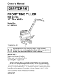
CONGRATULATIONS on your purchase of a new tiller. It
has been designed, engineered and manufactured to give
you the best possible dependability and performance.
Should you experience any problems you cannot easily
remedy, please contact your nearest authorized service
center. We have competent, well-trained technicians and
the proper tools to service or repair this unit.
Please read and retain this manual. The instructions will
enable you to assemble and maintain your tiller properly.
Always observe the "SAFETY RULES".
IN THE STATE OF CALIFORNIA, A SPARK ARRESTER IS
REQUIRED BY LAW (SECTION 4442 OF THE CALIFORNIA
PUBLIC RESOURCES CODE). OTHER STATES MAY HAVE
SIMILAR LAWS. FEDERAL LAWSAPPLYON FEDERAL LANDS.
SEE YOUR AUTHORIZED SERVICE CENTER/DEPARTMENT
FOR SPARK ARRESTER.
TABLE OF CONTENTS
MAINTENANCE ......................................................
10=12
SERVICE & ADJUSTMENTS ................................. 13=15
STO RAG E ....................................................................
16
TROUBLESHOOTING .................................................
17
REPAIR PARTS ......................................................
18=23
WARRANTY ............................................................
24=27
3
ASSEMBLY
Your new tiller has been assembled at the factory with exception of those parts left unassembled for shipping purposes.
To ensure safe and proper operation of your tiller all parts and hardware you assemble must be tightened securely. Use
the correct tools as necessary to insure proper tightness.
TOOLS
REQUIRED
FOR ASSEMBLY
OPERATOR'S
POSITION
(See Fig. 1)
When right or left hand is mentioned in this manual, it
means when you are in the operating position (standing
behind tiller handles).
A socket wrench set will make assembly easier. Standard
wrench sizes are listed.
(1) Utility knife
(1) Screwdriver
FRONT
(1) Pair of pliers
(2) 1/2" wrenches
LEFT
RIGHT
OPERATOR'S
POSITION
Fig. 1
CONTENTS
OF HARDWARE
PACK
@
(2) Carriage Bolts 5/16-18 UNC x 2-1/2
(2) Flange Locknuts
5/16-18 UNC
(1) Manual
//'
(2) Hex Bolts 5/16-18 x 1-1/4
@
kh
(1) Bottle Engine Oil
(2) Hex Nuts 5/16-18
4
@
(2) Lock Washers
5/16
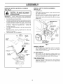
ASSEMBLY
INSTALL DEPTH STAKE
(See Fig. 3)
UNPACK CARTON & INSTALL HANDLE
(See Fig. 2)
&
CAUTION:
Be careful of exposed
staples when handling or disposing of
cartoning material.
•
Remove screws securing depth stake to skid and
discard the screws.
•
Remove plastic film from engine.
NUT
LOCK
WASHER
•
Loosen nut '_'.
•
Insert stake support between engine bracket halves
with stake spring down.
Bolt stake support to engine brackets with bolts, lock
washers and nuts. Tighten securely. Tighten nut '_'.
Depth stake must move freely. If it does not, loosen
support bolt.
•
iMPORTANT:
WHEN UNPACKING AND ASSEMBLING
TILLER, BE CAREFUL NOTTO STRETCH OR KINK CABLE(S).
•
Cut cable ties securing handles.
•
Slowly lift handle assembly up, route cable(s) as shown
and align handle holes with handle panel hole and slot.
•
Loosely assemble hardware as shown. Be sure the
shorter (1" long) hex bolt is assembled in lower hole
of handle. Repeat for opposite side.
Tighten all
hardware securely.
•
Cut cable ties securing tiller to skid and remove tiller
from skid.
•
ENGINE BRACKET
HALVES
NUT "A"
DEPTH STAKE
SUPPORT
STAKE
SPRING
DEPTH
STAKE
TILLER
HANDLE
SUPPORT
BOLT
FLAT
WASHER
HEX BOLTS,
LOCK WASHERS,
AND HEX NUTS
HEX BOLT
5/16-18X1-1/4"
Fig. 3
HEX BOLT
5/16-18Xl"
HANDLE
•
HANDLE
PANEL
BOLTS
CABLE(S]
TILLER
HANDLES
ASSEMBLY
Handle height may be adjusted to better suit operator.
(See "HANDLE HEIGHT" in the Service and Adjustments section of this manual).
TILLING
•
PLASTIC
HEIGHT
WIDTH
Tilling width may be adjusted to better handle your
tilling conditions (See "TINE ARRANGEMENT" in the
Service and Adjustments section of this manual).
TIN E OPERATION
•
Fig. 2
5
Check tine operation before first use. (See "TINE OPERATION CHECK" in the Service and Adjustments
section of this manual).
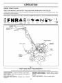
OPERATION
KNOW YOUR TILLER
READ THIS MANUAL
AND SAFETY
RULES
BEFORE
OPERATING
YOUR TILLER.
Compare the illustrations with your tiller to familiarize yourself with the location of various controls and adjustments. Save
this manual for future reference.
These symbols may appear on your Tiller or in literature supplied with the product. Learn and understand their meaning.
TILLING
FORWARD
N R&
NEUTRAL
REVERSE
CAUTION
ENGINE
OR WARNING
ON
6
_
ENGINE
FAST
IXI
SLOW
_--_
CHOKE
_
FUEL
STopRUN _
OIL
OFF
FORWARD TINE
CONTROL
\
REVERSE TINE
CONTROL
I
\
\
\
\
CHOKE CONTROL
THROTTLE
\
DEPTH STAKE
TINE
RECOIL
STARTER
HANDLE
Fig. 4
MEETS ANS! SAFETY
REQUIREMENTS
Our tillers conform to the safety standards of the American National Standards Institute.
CHOKE CONTROL - Used when starting a cold engine.
REVERSE TINE CONTROL - Engages tines in reverse
RECOIL STARTER HANDLE - Used to start the engine.
direction.
DEPTH STAKE - Controls forward speed and the depth at
which the tiller will dig.
THROTTLE CONTROL - Controls engine speed.
FORWARD TINE CONTROL - Engages tines in forward
direction.
6
OPERATION
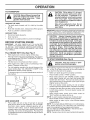
The operation of any tiller can result in foreign objects thrown into the eyes, which can result
in severe eye damage. Always wear safety glasses or eye shields before starting your til=
let and while tilling. We recommend a wide vision safety mask over spectacles or standard
safety glasses.
SAFETYGLAS$E$
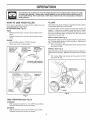
HOW TO USE YOUR TILLER
TILLING
Know how to operate all controls before adding fuel and
oil or attempting to start engine.
The speed and depth of tilling is regulated by the position
of the depth stake and wheel height.
STOPPING
The depth stake should always be below the wheels for
digging. It serves as a brake to slow the tiller's forward
motion to enable the tines to penetrate the ground. Also,
the more the depth stake is lowered into the ground the
deeper the tines will dig.
(See Fig. 5)
TINES
•
Release forward tine control to stop forward movement.
Release reverse tine control to stop reverse movement.
DEPTH STAKE (See Fig. 6)
Adjust depth stake by removing the hairpin clip and clevis
pin. Change depth stake to desired position. Replace the
clevis pin and hairpin clip.
•
For normal tilling, set depth stake at the second or third
hole from the top.
ENGINE
•
Move throttle control to "STOP" position.
Never use choke to stop engine.
REVERSE TINE
CONTROL iN
REVERSE TINE
CONTROL
"OFF" (UP)
POSITION
_
iN "ON" (DOWN)
POSiTiON
FORWARD
TINE CONTROL
iN "OFF" (UP)
POSITION
WHEELS (See Fig. 6)
Adjust wheels by removing the hairpin clip and clevis pin.
Change wheel position. Replace the hairpin clip and clevis
pin.
•
For normal tilling, set wheels at the second or third
hole from the top.
HAIRPIN CLiP
AND CLEVIS PiN
THROTTLE
CONTROL
DEPTH
STAKE
CHOKE__
WHEEL
CONTROL
Fig. 6
Fig. 5
TINE OPERATION
(See Fig. 5)
FORWARD
•
With reverse tine control in the "OFF" (up) position,
Squeeze forward tine control to handle.
REVERSE
•
With forward tine control in the "OFF" (up) position,
Squeeze reverse tine control to handle.
7
OPERATION
TO TRANSPORT
CAUTION: Fill to within 1/2" of top of
fuel tank to prevent spills and to allow
for fuel expansion.
If gasoline is ac=
cidentally spilled, move machine away
from area of spill. Avoid creating any
source of ignition until gasoline vapors
have disappeared.
CAUTION: Before lifting or transporting,
aJiow tiller engine and muffler to cool.
Disconnect spark plug wire. Drain
gasoline from fuel tank.
AROUND THE YARD
•
Wipe off any spilled oil or fuel. Do not
store, spill or use gasoline near an
open flame.
Tip depth stake forward until it is held by the stake
spring.
Push tiller handles down, raising tines off the ground.
Push or pull tiller to desired location.
IMPORTANT: WHEN OPERATING IN TEMPERATURES BELOW
32°F(0°C), USE FRESH, CLEAN WINTER GRADE GASOLINE
TO HELP INSURE GOOD COLD WEATHER STARTING.
AROUND TOWN
Disconnect spark plug wire.
Drain fuel tank.
•
CAUTION:
Alcohol
blended fuels (called
gasohol or using ethanol or methanol) can at=
tract moisture which leads to separation and
formation of acids during storage. Acidic gas
can damage the fuel system of an engine while
in storage. To avoid engine problems, the fuel
system should be emptied before storage of
30 days or longer. Drain the gas tank, start
the engine and let it run until the fuel lines
and carburetor are empty. Use fresh fuel next
season. See Storage Instructions for additional
information. Never use engine or carburetor
cleaner products in the fuel tank or permanent
damage may occur.
Transport in upright position to prevent oil leakage.
BEFORE
STARTING
ENGINE
IMPORTANT: BE VERY CAREFUL NOT TO ALLOW DIRT
TO ENTER THE ENGINE WHEN CHECKING OR ADDING
OIL OR FUEL. USE CLEAN OIL AND FUEL AND STORE IN
APPROVED, CLEAN, COVERED CONTAINERS. USE CLEAN
FILL FUNNELS.
FiLL ENGINE
•
•
•
•
•
•
WiTH OiL (See Fig. 7)
With engine level, remove engine oil filler plug.
Fill engine with oil to point of overflowing. For approximate capacity see "PRODUCT SPECIFICATIONS" on
page 3 of this manual.
Tilt tiller back on its wheels and then re-level.
TO START
(See Fig. 8)
=
m
i
With engine level, refill to point of overflowing if necessary. Replace oil filler plug.
For cold weather operation you should change oil for
easier starting (See "OIL VISCOSITY CHART" in the
Maintenance section of this manual).
To change engine oil, see the Maintenance section of
this manual.
CAUTION: Keep tine control in "OFF"
position when starting engine.
When starting engine for the first time or if engine has run
out of fuel, it will take extra pulls of the recoil starter to
move fuel from the tank to the engine.
•
Make sure spark plug wire is properly connected.
•
Place throttle control in "FAST" position.
•
Move choke control to full "CHOKE" position. Grasp
recoil starter handle with one hand and grasp tiller
handle with other hand. Pull rope out slowly until engine reaches start of compression cycle (rope will pull
slightly harder at this point).
•
Pull recoil starter handle quickly. Do not let starter
handle snap back against starter. Repeat if necessary.
•
If engine fires but does not start, move choke control
to half choke position. Pull recoil starter handle until
engine starts.
•
When engine starts, slowly move choke control to
"RUN" position as engine warms up.
NOTE: A warm engine requires less choking to start.
•
Move throttle control to desired running position.
•
Allow engine to warm up for a few minutes before
engaging tines.
NOTE: If at a high altitude (3000 feet) or in cold temperatures (below 32°F/0°C), the carburetor fuel mixturemay
need to be adjusted for best engine performance.
See "TO ADJUST CARBURETOR" in the Service and
Adjustments section of this manual.
NOTE: If engine does not start, see troubleshooting points.
LEVEL
OIL
OIL
FILLER
PLUG
Fig. 7
ADD GASOLINE
Fill to within 1/2 inch of top of fuel tank to prevent
spills and to allow for fuel expansion. Do not overfill.
Use fresh, clean, regular unleaded gasoline with a
minimum of 87 octane. (Use of leaded gasoline will
increase carbon and lead oxide deposits and reduce
valve life). Do not mix oil with gasoline. Purchase fuel
in quantities that can be used within 30 days to assure
fuel freshness.
ENGINE
=
8
OPERATION
•
•
You will find tilling much easier if you leave a row untilled between passes. Then go back between tilled
rows. (See Fig. 9) There are two reasons for doing
this. First, wide turns are much easier to negotiate than
about-faces. Second, the tiller won't be pulling itself,
and you, toward the row next to it.
Set depth stake and wheel height for shallow tilling
when working extremely hard soil or sod. Then work
across the first cuts at normal depth.
Fig. 8
BREAKING
iN YOUR TILLER
Break-in your belt(s), pulleys and tine control before you
actually begin tilling.
•
Start engine, tip tines off ground by pressing handles
down and engage tine control to start tine rotation.
Allow tines to rotate for five minutes.
•
Fig. 9
Checktine operation and adjust if necessary. See"TINE
OPERATION CHECK" in the Service and Adjustments
section of this manual.
TILLING
CULTIVATING
Cultivating is destroying the weeds between rows to prevent them from robbing nourishment and moisture from the
plants. At the same time, breaking up the upper layer of
soil crust will help retain moisture in the soil. Best digging
depth is 1"-3".
•
You will probably not need to use the depth stake. Begin
by tipping the depth stake forward until it is held by the
stake spring.
•
Cultivate up and down the rows at a speed which will
allow tines to uproot weeds and leave the ground in
rough condition, promoting no further growth of weeds
and grass (See Fig. 10).
HINTS
CAUTION: Until you are accustomed
to handling your tiller, start actual field
use with throttle in slow position.
To help tiller move forward, lift up the handles slightly (thus
lifting depth stake out of ground). To slow down the tiller,
press down on handles.
If you are straining or tiller is shaking, the wheels and depth
stake are not set properly in the soil being tilled. The proper
setting of the wheels and depth stake is through trial and
error and depends upon the soil condition. (The harder or
wetter the ground, the slower the engine and tine speed
needed. Under these poor conditions, at fast speed the
tiller will run and jump over the ground).
A properly adjusted tiller will dig with little effort from the
operator.
•
Tilling is digging into, turning over, and breaking up
packed soil before planting. Loose, unpacked soil helps
root growth. Best tilling depth is 4"-6". A tiller will also
clear the soil of unwanted vegetation. The decomposition
of this vegetable matter enriches the soil. Depending
on the climate (rainfall and wind), it may be advisable
to till the soil at the end of the growing season to further
condition the soil.
•
Soil conditions are importantfor proper tilling. Tines will
not readily penetrate dry, hard soil which may contribute
to excessive bounce and difficult handling of your tiller.
Hard soil should be moistened before tilling; however,
extremely wet soil will "ball-up" or clump during tilling.
Wait until the soil is less wet in order to achieve the
best results. When tilling in the fall, remove vines and
long grass to prevent them from wrapping around the
tine shaft and slowing your tilling operation.
Fig. 10
9
MAINTENANCE
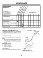
MAINTENANCE
SCHEDULE
FILL IN DATES
AS YOU COMPLETE
REGULAR SERVICE
Check Engine Oil Level
SERVICE
v'
v'
Change Engine Oil
_1,2
Oil Pivot Points
V t
Inspect Spark Arrester/Muffler
Inspect Air Screen
DATES
V _
V'
Clean or Replace Air Cleaner Cartridge
!_2
Clean Engine Cylinder Fins
V'
Replace Spark Plug
!_
1 - Change more often when operating under a heavy load or in high ambient temperatures,
2 - Service more often when operating in dirty or dusty conditions,
GENERAL
RECOMMENDATIONS
LUBRICATION
CHART
The warranty on this tiller does not cover items that have
been subjected to operator abuse or negligence. To receive
full value from the warranty, operator must maintain tiller
as instructed in this manual.
TINE CONTROL
Some adjustments will need to be made periodically to
properly maintain your tiller.
All adjustments in the Service and Adjustments section
of this manual should be checked at least once each
(_ ENGINE
season.
•
Once a year you should replace the spark plug, clean
or replace air filter, and check tines and belt for wear.
A new spark plug and clean air filter assure proper
air-fuel mixture and help your engine run better and
last longer.
BEFORE
•
•
•
EACH USE
Check engine oil level.
Check tine operation.
Check for loose fasteners.
/
LUBRICATION
Keep unit well lubricated (See "LUBRICATION
(_) IDLER
ARM
CHART")
(DSAE 30 OR 10W-30 MOTOR OIL
QREFER TO MAINTENANCE "ENGINE"
10
SECTION
MAINTENANCE
Disconnect spark plug wire before performing any maintenance (except carburetor adjustment) to
prevent accidental starting of engine.
Prevent fires! Keep the engine free of grass, leaves, spilled oil, or fuel. Remove fuel from tank
before tipping unit for maintenance. Clean muffler area of all grass, dirt, and debris.
Do not touch hot muffler or cylinder fins as contact may cause burns.
ENGINE
LUBRiCATiON
OiL
DRAIN
PLUG
Use only high quality detergent oil rated with API service
classification SG-SL. Select the oil's SAE viscosity grade
according to your expected temperature.
oF
°O
104
40
86
l_
__
m
o
\
OIL LEVEL
30
w
68
OIL FILLER
PLUG
20
lO
0
32
o
14
-10
-4
-20
Fig. 12
-30
-22
AiR CLEANER
Service air cleaner cartridge every 50 hours, more often
if engine is used in very dusty conditions.
•
Loosen air cleaner screws, one on each side of
cover.
•
Remove air cleaner cover.
Fig. 11
NOTE: Although multi-viscosity oils (5W-30, 10W-30, etc.)
improve starting in cold weather, these multi-viscosity oils
will result in increased oil consumption when used above
32°F (0°C). Check your engine oil level more frequently to
avoid possible engine damage from running low on oil.
Change the oil after every 50 hours of operation or at
least once a year if the tiller is not used for 50 hours in
one year.
Check the crankcase oil level before starting the engine
and after each five (5) hours of continuous use. Add SAE
30 motor oil or equivalent. Tighten oil filler plug securely
each time you check the oil level.
•
Carefully remove air cleaner cartridge. Be careful. Do
not allow dirt or debris to fall into carburetor.
•
•
•
Clean by tapping gently on a flat surface.
If very dirty or damaged, replace cartridge.
Clean and replace cover. Tighten screws securely.
&
TO CHANGE ENGINE OIL (See Figs. 11 and 12)
Determine temperature range expected before oil change.
All oil must meet API service classification SG-SL.
•
Be sure tiller is on level surface.
•
•
Oil will drain more freely when warm.
Catch oil in a suitable container.
•
•
•
Remove drain plug.
Tip tiller forward to drain oil.
After oil has drained completely, replace oil drain plug
and tighten securely.
Remove oil filler plug. Be careful not to allow dirt to
enter the engine.
Refill engine with oil. See "FILL ENGINE WITH OIL"
in the Operation section of this manual.
•
•
(See Fig. 13)
CAUTION: Petroleum solvents, such as
kerosene, are not to be used to clean
cartridge. They may cause deterioration
of the cartridge.
Do not oil cartridge.
Do not use pressurized air to clean or
dry cartridge.
COVER_
AIR
R CLEANER
00% 7
CARTR,0GE
Fig. 13
11
MAINTENANCE
COOLING
SYSTEM
SPARK
(See Fig. 14)
PLUG
Your engine is air cooled. For proper engine performance
and long life keep your engine clean.
•
Clean air screen
frequently using a stiff-bristled
brush.
Replace spark plugs at the beginning of each tilling season or after every 50 hours of use, whichever comes first.
Spark plug type and gap setting is shown in "PRODUCT
SPECIFICATIONS" on page 3 of this manual.
•
•
TRANSMISSION
Remove blower housing and clean as necessary.
Keep cylinder fins free of dirt and chaff.
MUFFLER
CYLINDER
Your transmission is sealed and will only require lubrication
if it is serviced.
FINS
CLEANING
Do not clean your tiller when the engine and transmission
are hot. We do not recommend using pressurized water
(garden hose, etc.) to clean your unit unless the gasket
area around the transmission and the engine muffler, air
filter and carburetor are covered to keep water out. Water
in engine will shorten the useful life of your tiller.
•
Clean engine, wheels, finish, etc. of all foreign matter.
•
Keep finished surfaces and wheels free of all gasoline,
oil, etc.
•
Protect painted surfaces with automotive type wax.
MUFFLER
Do not operate tiller without muffler. Do not tamper with
exhaust system. Damaged mufflers or spark arresters could
create a fire hazard. Inspect periodically and replace if
necessary. If your engine is equipped with a spark arrester
screen assembly, remove every 50 hours for cleaning and
inspection. Replace if damaged.
12
SERVICE AND ADJUSTMENTS
CAUTION: Disconnect spark plug wire from spark plug and place wire where it cannot come into
contact with plug.
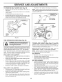
TILLER
TO ADJUST
HANDLE
HEIGHT
MID=WIDTH TILLING =24" PATH (See Fig. 17)
•
Assemble holes '_' in tine hubs to holes "C" in tine
shaft.
(See Fig. 15)
Factory assembly has provided lowest handle height. Select
handle height best suited for your tilling conditions. Handle
height will be different when tiller digs into soil.
•
If a higher handle height is desired, loosen the four
nuts securing handle panel to engine brackets.
•
Slide handle panel to desired location.
•
Tighten the four nuts securely.
A
C
C
A
6o]
[o_
Fig. 17
ENGINE
BRACKETS
HANDLE
NARROW TILLING/CULTIVATING
Fig. 18)
•
Remove outer tines.
NUTS (ALSO 2
ON LEFT SIDE
OF TILLER)
OII
- 12-3/4" PATH (See
IIO
ool
tine
6
INNER TINES ONLY
Fig. 15
Fig. 18
TINE ARRANGEMENT
Your outer tines can be assembled in several different ways
to suit your tilling or cultivating needs.
j
CAUTION:
Tines are sharp.
Wear
gloves or other protection when ban=
dling tines.
NOTE: When reassembling outer tines, be sure right tine
assembly (marked "R") and left tine assembly (marked "LL')
are mounted to correct side of tine shaft.
j
|
NORMAL TILLING = 26" PATH (See Fig. 16)
•
Assemble holes '_:' in tine hubs to holes "B" in tine
shaft.
CLEVIS
OUTER
fPIN
TINE
%N lll .
i o
ofl
HAIRPIN CLIP
INNER TINE
Fig. 16
13
SERVICE AND ADJUSTMENTS
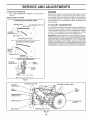
TO REMOVE
•
•
e
e
BELT GUARD
•
(See Fig. 19)
Remove two (2) cap nuts and washers from side of
belt guard.
Loosen (do not remove) tine shield nut on underside
of tine shield.
Recheck in "ON" position and adjust if necessary.
NOTE: If"ON" position check required adjustment, recheck
"OFF" position adjustment to insure tines do not rotate when
control is "OFF" (up).
Pull belt guard out and away from unit.
Replace belt guard by reversing above procedure. Be
sure slot in bottom of belt guard is under head of tine
shield bolt and all nuts are tightened securely.
....
BODY
.CAP NUTS
AND WASHERS
BEN
GUARD
CABLE
CLiP
FORWARD TINE
CONTROL IN "OFF"
(UP) POSITION
TINECONTROL
"ON'POSITION
TINE
CONTROL
CABLE
SHIELD
TINE
NUT
Fig. 19
TINE OPERATION
CHECK
(See Fig. 20)
Fig. 20
WARNING: Disconnect spark plug wire
from spark plug to prevent starting while
checking tine operation.
TO REPLACE
Replace V-belts if they have stretched considerably or if
they show cracks or frayed edges. There are two (2) V-belts
-forward (inside) and reverse (outside).
For proper tine operation, forward tine control lever must be
against control body and all slack removed from inner wire of
control cable when control is in the "OFF" (up) position.
Belt guard must be removed to service belts. See "TO
REMOVE BELT GUARD" in this section of manual.
If lever and cable are loose, loosen cable clip at lower end of
cable. Pull up on cable to remove slack, without extending
spring on end of cable, and retighten cable clip.
NOTE: Observe carefully routing of both belts and location
of all belt guides before removing belts.
BELT REMOVAL
•
Remove reverse idler pulley from idler arm.
•
Remove reverse (outside) V-belt.
•
Remove forward (inside) V-belt from transmission pulley
first and then from engine pulley.
FINAL CHECK "OFF" POSITION
•
•
•
•
With tine control "OFF" (up), push down on handle to
raise tines off the ground.
Slowly pull recoil starter handle while observing tines.
Tines should not rotate.
BELT REPLACEMENT
If tines rotate, inner wire of control cable is too tight
which is extending lower spring and engaging tines.
Loosen cable clip and push down on cable only enough
to relieve spring tension. Tighten cable clip.
Recheck in "OFF" position and adjust if necessary.
•
•
FINAL CHECK "ON" POSITION
•
•
•
V=BELTS (See Figs. 21 and 22)
•
With tine control "ON" (held down to handle) push down
on handle to raise tines off the ground.
Slowly pull recoil starter handle while observing tines.
Tines should rotate forward.
If tines do not rotate, inner wire of control cable is too
loose. Loosen cable clip and pull cable up to remove
slack and retighten clip.
•
14
Install new forward (inside) V-belt to engine pulley first
then to transmission pulley. Be sure belt is positioned
on inside groove of both pulleys, inside all belt guides
and rests on idler pulley.
Before installing reverse (outside) V-belt, turn belt"inside
out". Twist so wide, flat surface of belt is to inside.
Wrap V-belt around reverse idler pulley and reassemble
idler to idler arm. Tighten securely. Be sure belt is
between reverse idler pulley and idler arm pin.
Install belt to outside groove of transmission pulley. Be
sure belt is inside all belt guides and rests on outside
groove of engine pulley.
SERVICE AND ADJUSTMENTS
ENGINE
CHECK TINE OPERATION
•
See "TINE OPERATION CHECK" in this section of
manual.
Maintenance, repair, or replacement of the emission control
devices and systems, which are being done at the customers expense, may be performed by any non-road engine
repair establishment or individual. Warranty repairs must
be performed by an authorized engine manufacturer's
service outlet.
REPLACE BELT GUARD
FORWARD MOTION (iNSiDE) V-BELT
ENGINE PULLEY
/ I _ \
TRANSMISSION
BELT GUIDE
TO ADJUST
PULLEY
The carburetor has been preset atthe factory and adjustment
should not be necessary.
However, engine performance
can be affected by differences in fuel, temperature,
altitude
or load. If the carburetor
does need adjustment,
contact
your nearest authorized
service center/department
iMPORTANT: NEVERTAMPERWITHTHE
ENGINE GOVERNOR,
WHICH IS FACTORY SET FOR PROPER ENGINE SPEED.
OVERSPEEDING THE ENGINE ABOVE THE FACTORY HIGH
SPEED SETTING CAN BE DANGEROUS. IFYOU THINKTHE
ENGINE-GOVERNED
HIGH SPEED NEEDS ADJUSTING,
CONTACTYOUR NEARESTAUTHORIZED
SERVICE CENTER/
DEPARTMENT, WHICH HAS THE PROPER EQUIPMENT AND
EXPERIENCE TO MAKE ANY NECESSARY ADJUSTMENTS.
REVERSE
IDLER PULLEY
BELT GUIDE
FORWARD
IDLER PULLEY
REVERSE (OUTSIDE) V-BELT
REVERSE
IDLER
PULLEY
I
CARBURETOR
/
\
ENGINE
PULLEYX
FORWARD
iDLER PULLEY
belts
10
FRONT VIEW REFERENCE
REVERSE
_
iDLER
Fig. 21
REVERSE
IDLER PULLEY
REVERSEIDLER
ARM
REVERSE
(OUTSIDE) V-BELT
BELT
GUARD
BOLT
IDLER
ARM
FORWARD
(iNSIDE) V=BELT
ENGINE PULLEY
BELT GUIDE
TRANSMISSION
PULLEY
FORWARD IDLER PULLEY
Fig. 22
15
STORAGE
ENGINE OiL
Immediately prepare your tiller for storage at the end of the
season or if the unit will not be used for 30 days or more.
Drain oil (with enginewarm) and replacewith clean oil. (See
"ENGINE" in the Maintenance section of this manual).
WARNING: Never store the tiller with
gasoline in the tank inside a building
where fumes may reach an open flame
or spark. AIIowthe engine to cool before
storing in any enclosure.
CYLINDER(S)
•
•
TILLER
•
•
•
•
•
•
Clean entire tiller (See "CLEANING" in the Maintenance
section of this manual).
Inspect and replace belts, if necessary (See belt replacement instructions inthe Service and Adjustments
section of this manual).
Lubricate as shown in the Maintenance section of this
manual.
•
Replace with new spark plug.
OTHER
•
•
Do not store gasoline from one season to another.
Replace your gasoline can if your can starts to rust.
Rust and/or dirt in your gasoline will cause problems.
•
If possible, store your unit indoors and cover it to give
protection from dust and dirt.
•
Cover your unit with a suitable protective cover that
does not retain moisture. Do not use plastic. Plastic
cannot breathe which allows condensation to form and
will cause your unit to rust.
IMPORTANT: NEVER COVER TILLER WHILE ENGINE AND
EXHAUST AREAS ARE STILL WARM.
Be sure that all nuts, bolts and screws are securely
fastened. Inspect moving parts for damage, breakage
and wear. Replace if necessary.
Touch up all rusted or chipped paint surfaces; sand
lightly before painting.
ENGINE
FUEL SYSTEM
iMPORTANT: IT IS IMPORTANTTO PREVENT GUM DEPOSITS
FROM FORMING IN ESSENTIAL FUEL SYSTEM PARTS SUCH
AS THE CARBURETOR, FUEL FILTER, FUEL HOSE, OR TANK
DURING STORAGE. ALSO, EXPERIENCE INDICATES THAT
ALCOHOL BLENDED FUELS (CALLED GASOHOL OR USING
ETHANOL OR METHANOL) CAN ATTRACT MOISTURE WHICH
LEADS TO SEPARATION AND FORMATION OFACIDS DURING
STORAGE. ACIDIC GAS CAN DAMAGE THE FUEL SYSTEM
OF AN ENGINE WHILE IN STORAGE.
•
Remove spark plug.
Pour 1 ounce (29 ml) of oil through spark plug hole
into cylinder.
Pull starter handle slowly several times to distribute
oil.
Drain the fuel tank.
•
Start the engine and let it run until the fuel lines and
carburetor are empty.
•
Never use engine or carburetor cleaner products in
the fuel tank or permanent damage may occur.
NOTE: Fuel stablizer is an acceptable alternative in
minimizing the formation of fuel gum deposits during
storage. Add stabilizer to gasoline in fuel tank or storage
container. Always follow the mix ratio found on stablizer
container. Run engine at least 10 minutes after adding
stablizer to allow the stabilizer to reach the carburetor.
Do not drain the gas tank and carburetor if using fuel
stabilizer.
16
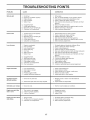
TROUBLESHOOTING
PROBLEM
POINTS
CAUSE
Will not start
CORRECTION
1.
Out of fuel.
2.
3.
4.
5.
Engine not "CHOKED"
Engine flooded.
Dirty air cleaner.
Water in fuel.
6.
7.
8.
9.
Clogged fuel tank.
Loose spark plug wire.
Bad spark plug or improper gap.
Carburetor out of adjustment.
7.
8.
9.
Make sure spark plug wire is seated properly on plug.
Replace spark plug or adjust gap.
Make necessary adjustments.
Herd to start
1. Throttle control not set properly.
2. Dirty air cleaner.
3. Bad spark plug or improper gap.
4. Stale or dirty fuel.
5. Loose spark plug wire.
6. Carburetor out of adjustment.
1.
2.
3.
4.
5.
6.
Place throttle control in "FAST" position.
Clean or replace air cleaner cartridge.
Replace spark plug or adjust gap.
Drain fuel tank and refill with fresh gasoline.
Make sure spark plug wire is seated properly on plug.
Make necessary adjustments.
Loss of power
1.
2.
3.
4.
5.
Engine is overloaded.
Dirty air cleaner.
Low oil level/dirty oil.
Faulty spark plug.
Oil in fuel.
6.
7.
Stale or dirty fuel.
Water in fuel.
1.
2.
3.
4.
5.
6.
7.
Set depth stake and wheels for shallower tilling.
Clean or replace air cleaner cartridge.
Check oil level/change oil.
Clean and regap or change spark plug.
Drain and clean fuel tank and refill, and clean carburetor.
Drain fuel tank and refill with fresh gasoline.
Drain fuel tank and carburetor, and refill tank with fresh
8.
gasoline.
Remove fuel tank and clean.
8.
9.
10.
11.
12.
13.
Engine
overheats
1.
properly.
Fill fuel tank.
2.
3.
4.
5.
See "TO START ENGINE" in the Operation section.
Wait several minutes before attempting to start.
Clean or replace air cleaner cartridge.
Drain fuel tank and carburetor, and refill tank with fresh
gasoline.
6. Remove fuel tank and clean.
Clogged fuel tank.
Spark plug wire loose.
Dirty engine air screen.
Dirty/clogged muffler.
Carburetor out of adjustment.
Poor compression.
9.
10.
11.
12.
13.
Connect and tighten spark plug wire.
Clean engine airscreen.
Clean/replace muffler.
Make necessary adjustments.
Contact an authorized service center/department.
1.
2.
3.
4.
5.
Low oil level/dirty oil.
Dirty engine air screen.
Dirty engine.
Partially plugged muffler.
Improper carburetor adjustment.
1.
2.
3.
4.
Check oil level/change oil.
Clean engine air screen.
Clean cylinder fins, air screen, muffler area.
Remove and clean muffler.
5.
Adjust carburetor
1.
Ground too dry and hard.
1.
Moisten ground or wait for more favorable soil
conditions.
2.
Wheels
2.
Adjust wheels and depth stake.
Soil bells up or clumps
1.
Ground too wet.
1.
Wait for more favorable soil conditions.
Engine rune but
won't move
tiller
1. Tine control is not engaged.
2. V-belt not correctly adjusted.
3. V-belt is off pulley(s).
1.
2.
3.
Engage tine control.
Inspect/adjust V-belt.
Inspect V-belt.
Engine rune but
when tilling
labors
1. Tilling too deep.
2. Throttle control not properly adjusted.
3. Carburetor out of adjustment.
1.
2.
3.
Set depth stake for shallower tilling.
Check throttle control setting.
Make necessary adjustments.
Excessive bounce/
difficult handling
and depth
stake
incorrectly
adjusted.
17
to richer position.
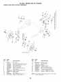
TILLER - MODEL NO. 917.250090
HANDLE
ASSEMBLY
3
16
19
2
29
\
\
\
C
12
13
F-handle
KEY
NO.
1
2
3
4
5
6
7
8
10
11
12
assy 6
PART
NO.
137176X668
72140512
165787
166376X498
73680500
19111116
19121414
74760520
10040500
73220500
98000129
KEY
NO.
DESCRIPTION
13
14
16
19
2O
29
3O
Panel, Control
Bolt, RDHD 5/16-18 x 1 1/2
Grip, Handle
Handle, LH Double Bend
Nut, Crown Lock 5/16 -18
Washer 11/32 x 11/16 x 16 Ga.
Washer 3/8 x 7/8 x 14 Ga.
Bolt Fin Hx 5/16-18 x 1.25
Washer Lock 5/16
Nut, Fin Hx 5/16-18
Nut, Flange
PART
NO.
180847
9209RX668
166381X498
188562
188555
12000059
181580
DESCRIPTION
Bolt, RDHD 5/16-18 x 3/4
Assembly, Panel
Handle, RH Double Bend
Lever, Control, Tine
Pin, Pivot
Retainer, Ring
Routing Clip
NOTE: All component dimensions given in U.S. inches.
1 inch = 25.4 mm
18
TILLER
- MODEL NO. 917.250090
BELT GUARD AND PULLEY ASSEMBLY
i!
41
lO
112
14
15
24
16
23
/
22
21
32
18
belt
KEY
NO.
1
2
3
4
5
6
7
8
9
10
11
12
13
14
15
16
17
18
19
2O
PART
NO.
439162X479
9484R
086777
74610812
73680600
19131316
2009J
159238X479
74780632
194630X668
19091016
104213X
72140406
133035
2614J
12000028
2649M
151236
188502
12000036
guard
14
KEY
NO.
21
22
23
24
25
26
27
28
29
3O
DESCRIPTION
Assembly, Bracket, Belt Guard
Clip, Cable
Screw #10-24 x 1/2
Bolt, Hex Head 1/2-20 x 3/4
Nut, Lock 3/8-16
Washer 13/32 x 13/16 x 16 Ga.
Pulley, Idler, Reverse
Assembly, Arm, Reverse Idler
Cap screw, Hex Head 3/8-16 x 2.00
Guard, Belt
Washer 9/32 x 5/8 x 16 Ga.
Nut, Cap 1/4- 20
Bolt, Carriage 1/4-20 x 3/4
V-Belt (Forward Motion)
V-Belt (Reverse)
Ring, Retainer
Key, Square
Sheave, Transmission "Flat"
Bolt, Belt Guard
Ring, Klip
31
32
41
42
PART
NO.
73350600
161806
175377X479
74760620
106968
73350500
73220400
10040400
109227X
23200404
101189L
151223
180307
138909
DESCRIPTION
Nut, Hex, Jam 3/8-16
Pulley, Idler
Arm, Idler
Bolt 3/8-16 x 1-1/4
Shaft, Idler Arm
Nut, Hex, Jam 5/16-18
Nut, Hex 1/4-20
Washer, Lock 1/4
Pad, Idler
Screw, Set, Socket, Headless
C.R 1/4-20 x 1/4
Sheave, Engine
Sheave, Transmisison
Spring Extension
Spacer
NOTE: All component dimensions given in U.S. inches.
1 inch = 25.4 mm
19
TILLER
- MODEL NO. 917.250090
WHEEL AND DEPTH STAKE ASSEMBLY
16
25
KEY
NO.
1
2
3
4
5
6
7
8
9
10
11
13
PART
NO.
9194R
74760520
74760512
73220500
10040500
73800600
4921H
1952JX479
122233X479
4929H
74780628
1951JX479
KEY
NO.
DESCRIPTION
15
16
17
19
20
21
22
24
25
Pin, Clevis
Bolt, Hex Head 5/16-18 x 1-1/4
Bolt, Hex Head 5/16-18 x 3/4
Nut, Hex 5/16-18
Washer, Lock 5/16
Locknut, w/washer 3/8-16
Clip, Hairpin
Support, Depth Stake, R.H.
Stake, Depth
Pin, Clevis
Bolt, Hex 3/8-16 x 1-3/4
Support, Depth Stake, L.H.
PART
NO.
5388JX004
121117X
193851X613
9190RX479
73680600
74760516
73800500
73970500
19171416
DESCRIPTION
Spring, Stake
Bolt, Shoulder
Wheel
Bracket, Wheel
Locknut, Crown 3/8-16
Bolt, Hex Head 5/16-18 x 1
Locknut, w/insert 5/16-18
Locknut, Flange 5/16-18 unc
Washer 17/32 x 7/8 x 16 Ga.
NOTE: All component dimensions given in U.S. inches.
1 inch = 25.4 mm
2O
TILLER - MODEL NO. 917.250090
TINE ASSEMBLY
2
i
/
I
6
/
/
/
5
tine_ipb_3
KEY
NO,
1
2
3
4
5
6
PART
NO,
156934X479
3146R
156932X479
156931X479
156933X479
4929H
DESCRIPTION
Tine, Outer, R.H.
Retainer, Spring
Tine, Inner, R.H.
Tine, Inner, L.H.
Tine, Outer, L.H.
Rivet Pan Hd Drilled 1/4 Dia.
NOTE: All component dimensions given in U.S. inches•
1 inch = 25.4 mm
21
TILLER - MODEL NO. 917.250090
TRANSMiSSiON
20iL_
2
/
3
11
118
14
11
21
I
lO
21
12
transmission
KEY
NO.
1
2
3
5
6
7
8
10
11
12
14
PART
NO.
74760524
74780652
19131311
73900600
9057RX668
188195X479
165834X479
970500
187912
151222
446548
KEY
NO.
DESCRIPTION
Bolt, Hex 5/16-18 x 1-1/2 Gr. 2
Bolt, Hex 3/8-16 x 3-1/4
Washer 13/32 x 13/16 x 11
Locknut 3/8-16
Shield, Tine
Bracket, Engine, R.H.
Bracket, Engine, L.H.
Nut, Hex 5/16-18
Bolt, Hex Head 5/16-18 x 2.5
Transmission
Spacer, Split
PART
NO.
16
17
18
19
20
19091412
19092016
10040400
74610412
21
751153
27
DESCRIPTION
Washer 9/32 x 7/8 x 12 Ga.
Washer 9/32 x 1-1/4 x 16 Ga.
Washer, Lock 1/4
Bolt, Hex 1/4-28 x 3/4 Gr. 5
Engine Briggs Model 12T4021613-F8 (446085) (Order parts from
engine manufacturer.
Nut 5/16-18
NOTE: All component dimensions given in U.S. inches.
1 inch = 25.4 mm
22
TILLER
- MODEL NO. 917.250090
DECALS
7
5
13
12
10
©
3
KEY
NO.
1
2
3
5
6
7
8
9
10
12
13
PART
NO.
440613
429196
439989
110614
158700
158701
120076X
422972
409143
432278
423830
447254
DESCRIPTION
Decal, Logo
Decal, Logo
Decal, Logo
Decal, Hand Placement
Decal, Control Forward
Decal, Control Reverse
Decal, Warning, Rotating Tines
Decal, Tine Shield
Decal, Tank
Decal, Air Cleaner
Decal, Ethanol E85 Warning
Manual, Owner's (English/French)
23
6
Husqvarna
Consumer
Wheeled
Products
- Limited
Warran D
Husqvarna
warrants to the original retail purchaser that this Husqvarna®
product is free from defects in material
or workmanship
under normal use and maintenance from the date of retail purchase for the applicable Warranty Period shown on Exhibit A. Certain
components (e.g., engines and transmissions)
are excluded from coverage, and other limitations apply, as described in this document.
Husqvarna will repair or replace at its discretion,
any defective product or part covered by the Limited Warranty, fiee of charge at any
authorized
exclusions
Husqvarna
Servicing
Dealer/Center
using original OEM Husqvarna
replacement
described below. Husqvarna
does not offer an over-the-counter
exchange program.
parts, subject
to the limitations
and
THIS LIMITED
WARRANTY
IS THE SOLE EXPRESS
WARRANTY
PROVIDED
BY HUSQVARNA.
ANY WARRANTY
THAT MAY BE IMPLIED
BY LAW (INCLUDING
ANY IMPLIED
WARRANTY
OF FITNESS
FOR A PARTICULAR
PURPOSE
OR USE AND IMPLIED
WARRANTY
OF MERCHANTABILITY)
IS LIMITED
TO THE DURATION
OF THE
APPLICABLE
WARRANTY
PERIOD
UNDER
THIS LIMITED
WARRANTY.
THIS LIMITED
WARRANTY
MAY
BE
MODIFIED
ONLY BY HUSQVARNA.
SOME STATES DO NOT ALLOW
LIMITATIONS
ON HOW LONG AN IMPLIED
WARRANTY
LASTS, SO THE ABOVE LIMITATIONS
MAY NOT APPLY TO YOU. THIS LIMITED WARRANTY
GIVES
YOU SPECIFIC LEGAL RIGHTS, AND YOU MAY ALSO HAVE OTHER RIGHTS WHICH VARY FROM STATE TO STATE.
THIS WARRANTY
IS GIVEN ONLY BY HUSQVARNA.
THE ABOVE REMEDIES
ARE THE EXCLUSIVE
REMEDIES
FOR
ANY BREACH
OF THIS LIMITED
WARRANTY.
HUSQVARNA
AND ITS AFFILIATED
COMPANIES
SHALL NOT BE
LIABLE FOR ANY SPECIAL,
INCIDENTAL
OR CONSEQUENTIAL
DAMAGE,
INCLUDING
LOST PROFITS
RESULTING
FROM ANY SUCH BREACH, AND ALL SUCH DAMAGES
ARE HEREBY DISCLAIMED.
SOME STATES DO NOT ALLOW
THE EXCLUSION
OR LIMITATION
OF INCIDENTAL
OR CONSEQUENTIAL
DAMAGES,
SO THE ABOVE LIMITATIONS
MAY NOT APPLY TO YOU.
LIMITATIONS
1. Engines, Transmissions
following:
and certain other components
AND EXCLUSIONS
are NOT covered.
This Limited Warranty does not cover any of the
(a) Engines and Attachments. Except where othmwise indicated on Exhibit A, all Engines and Attachments are not covered by
this warranty. In most cases, these items are NOT manufactured by Husqvarna in which case they may be covered separately by
their respective manufacturer's warranties if one is provided and included with the product at the time of purchase. All such
claims must be submitted and sent to the appropriate manufacturer or as othmwise directed in those separate warranties.
Husqvarna is not authorized to handle warranty adjustments or repairs on engines manufactured by Briggs & Stratton, Honda,
Kawasaki, or Kohler (exception
models equipped with LCT engines). Husqvarna does not assume any warranty obligation of
the other manufacturer's engines.
(b) TransmLs'sions. Except where othmwise indicated on Exhibit A, Transmission / Transaxle (including Drive Systems) are not
covered by this warranty. In most cases, these items are NOT manufactured by Husqvarna in which case they may be covered
separately by their respective manufacturer's warranties if one is provided and included with the product at the time of purchase.
The following transmission / transaxle manufacturers, Dana, Hydro-Gear, Tuff-Torq provide a warranty for the transmission /
transaxle to the ultimate purchaser or to Husqvarna. Husqvarna will assign the transmission / transaxle manufacturer's warranty
or any rights thereof to the original purchaser of the unit. To obtain transmission / transaxle warranty service, first contact the
retailer who you purchased the unit from. Should you require assistance or have any questions concerning transmission / transaxle
warranty coverage, contact Husqvarna directly at out website www.husqvarna.com
or call 800-487-5951 for an authorized
Husqvarna service provider. All such claims must be submitted and sent to the appropriate manufacturer or as othmwise directed
in those separate warranties. Husqvarna is not authorized to handle warranty adjustments or repairs on transmissions or transaxles.
Husqvarna does not assume any warranty obligation of the above listed manufacturers (for exceptions
see Exhibit A).
(c) E_wendable Parts. This Limited Warranty does not cover general maintenance parts and items ("Expendable
including without limitation spark plugs, bulbs, filters, lubricants, starter cords, belts, blades, and blade adapters.
Parts"),
(d) Emissions
(_ntrol
(_mponents.
This Limited Warranty does not cover Emissions control equipment and components
to the
extent regulated by the U.S. Environmental
Protection
Agency or similar state agencies.
Such equipment
and components
are
covered by a separate emission control warranty statement supplied with your new product.
Please consult this separate warranty
statement for details.
2.
Any
'Warranty
COMMERCIAL,
or a Shortened
institutional,
agricultural,
INSIT[TIONAL,
VVarranty
industrial,
Period
income
AGRICULT[t_kL,
Depending
producing,
on the product;
or rental
purposes.
IND[STRIAL,
there
is either
Please
refer
INCOME
NO WARRANTY
to Exhibit
PRODICING,
or a reduced
or
RENTAL
warranty
use
will
if the product
result
is used
in
either
No
lbr commercial,
A.
3. Owner's (Your) Responsibilities. To preserve your rights under this Limited Warranty, you must demonstrate reasonable care
and use of the product, including, following the preventative maintenance, storage, fuel and oil usages as prescribed in the enclosed
operator's manual. For example, the following items are the Owner's responsibility and are no___!
covered by this Limited Warranty:
a. Set-up and pre-delivery service, and engine tune-ups.
b. Adjustments after the first (30) thirty days of purchase and beyond, such as throttle cable, belt gnides adjustments.
24
c. Preventative
lnaintenance
as outlined
in the operator's
In addition, you lnUSt cease using the product ilmnediately
Husqvarna servicing dealer prior to any further use.
4.
Damages
resulting
from normal
aging,
damage other than that resulting from detects
worklnanship,
and therefore are NOT covered.
(a)
Abrasion
(b)
Tires damaged
(c)
Natural
(d)
Damage
manual.
upon any t:ailure or damage.
The product
should
be taken to an authorized
wear and tear or neglect are NOT covered.
The Limited Warranty
does not cover
in material or worklnanship.
The following are NOT considered
detects in material or
to mower decks;
by external
discoloration
punctures;
of materials
to cutting equipment
due to ultraviolet
light;
by way of contact with, rocks,
In addition, this Limited Warranty does not cover
related to or including any of the following:
or perforln
required
damages,
of the product
Abuse, misuse, neglect, modifications,
alterations, normal wear, improper servicing, use of unauthorized
attachments,
lubrication or engine t:ailure, due to the use of oils that do not meet Engine lnanu_:acturer's
specifications;
cleaning
Pressure
(j)
Use of spark plugs other than those meeting
(k)
Tampering with engine speed governor
engine speeds as listed in your operator's
(1)
Operation
or steam cleaning
perforlnance
or emission
manual;
components,
installed/removed
air filter, excessive
due to incorrect
emission
or modified
dirt, abrasives,
(o)
Dirt comaminated
grease or oil, use of incorrect type of greases
intervals, water or moisture damage, and/or improper storage;
(p)
Sprayers
(q)
Continued
or spraying
requirements
or running
listed in the operator's
engines
cutting shields,
salt water,
Failures due to improper set up, pre-delivery
servicing dealer during the warranty period;
use of product,
10% ethanol
(grain
alcohol)
or
lnoismre,
above
manual;
specified
and recolmnended
guards, or safety devices;
corrosion,
rust, varnish,
stale
fuel, or any
storage procedures;
(n)
pumping
a lnaxilnum
Lack of
the product;
of the unit with improperly
adverse reaction
which contains
manual;
fluids;
(i)
(m) Any removed/damaged
Gasohol
in the operator's
or neglect
(f)
(wood alcohol).
is approved;
as prescribed
and/or structures;
from abuse
Failure to provide
(h) Use of ether or any starting
services
materials
or t:ailures resulting
(e)
(g) Use of gasohol, containing methanol
15% MTBE (lnethyl/tertiary/butyl/ether)
lnaintenance
or other non-approved
lnalfunctions
service
caustic or flalmnable
after initial operational
HOW
or repair
materials,
problem
service
or oils,
by anyone
other
t:ailure to comply
lack of or broken
strainers;
than an authorized
with recolmnended
Husqvarna
greasing
or
or t:ailure occurs.
TO OBTAIN
SERVICE
5.
Authorized
Husqvarna
Servicing
Dealer/Center.
In order to obtain warranty coverage
it is your responsibility
(at your
expense) to deliver or ship your Husqvarna unit to an authorized Husqvarna Servicing Dealer/Center
and arrange for pick-up or return
of your unit after the repairs have been made. If you do not know the location of your nearest authorized Husqvarna Servicing Dealer,
call Husqvarna,
at 1-800-487-5951
during the hours of 8:00 AM to 8:00 PM Eastern Standard Time, or visit www.husqvarna.coln.
Should you require assistance or have questions concerning
this Limited Warranty, you may contact us at 800-487-5951
during the
hours of 8:00 AM to 8:00 PM Eastern Standard Time or contact us through the web at www.husqvarna.coln.
6.
Documentation
Required.
You lnUSt maimain and present Proof of purchase (including date, product model and, if applicable,
engine serial number) to an authorized
Husqvarna
Servicing Dealer for warranty service under this Limited Warranty.
Proof of
purchase
rests
solely
with
the owner-customer.
Husqvarna
encourages
you
to register
your product
online
at
www.asa.h_iscua_na.com
to help ensure, among other things, that you can be notified of ilnportant product inforlnation.
However,
registering your product is not a condition of warranty service.
Hnsqvarna
Consumer
Outdoor
Products
N.A., Inc.; Hnsqvarna
9335 Harris' Cornels' Parkway
Pr@ssional
Products,
Inc.
(7_arlotte, NC 28269
575 49 43-01 R3 2010
25
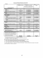
Consumer Wheeled Warranty Chart 2010
Exhibit A
Consumer
(personal,
household
Commercial
use only)
(any commercial,
professional,
institutional,
Rental
(any rental
usage)
arigculutral,
or income producing
use, other than Rental Use)
Product/Component
Frame,
Chassis,
Front Axle
5 Years
Engine*
Transmission
(if made by
Husqvarna/Peerless)
Transmission
Battery
NO WARRANTY
*
3 Years
NO WARRANTY
NO WARRANTY
1 Year Pro-rated
NO WARRANTY
NO WARRANTY
3 Years
NO WARRANTY
NO WARRANTY
*
NO WARRANTY
*
NO WARRANTY
1 Year Pro-rated
NO WARRANTY
NO WARRANTY
3 Years
NO WARRANTY
NO WARRANTY
1 Year Pro-rated
NO WARRANTY
1 Year
NO WARRANTY
(if third party) ......
Other Non-Expendable
Engine*
Transmission
Components
*
....
Battery
Other Non-Expendable
Engine*
Transmission
Components
*
**
**
Battery
1 Year Pro-rated
Engine*
Other Non-Expendable Components
2 Years
Engine*
90 days
*
Battery
Other Non-Expendable
_Thro_rs:,
Engine*
*
1 Year Pro-rated
2 Years
Components
NO WARRANTY
NO WARRANTY
90 days
*
NO WARRANTY
NO WARRANTY
....
*
Other Non-Expendable
Components
*
2 Years
rs
90 days
*
90 days
,,
....
Engine*
*
Battery
Other Non-Expendable
Tiller Tines
Engine*
Other Non-Expendab
• See Separate
NO WARRANTY
*
Engine
LCT Engines
Components
1 Year Pro-rated
2 Years
***
NO WARRANTY
NO WARRANTY
NO WARRANTY
*
2 Years
Consumer
*
1 Year
Commercial
e Components
Manufacturer's
on specific
or Manufacturer's
Snow Throwers
*
& Tillers,
Commercial
warranty,
parts
NO WARRANTY
NO WARRANTY
NO WARRANTY
*
90 days
Rental
warranty
warranty
through
•* See reference 1 (b) of the warranty statement.
RZ - Two (2) Year Consumer warranty, parts & labor, with Hydro-Gear
EZ - One (1) Year
*
Husqvarna.
Distributor
network.
& labor, with Husqvarna.
Two (2) Year Consumer warranty, parts & labor, with Hydro-Gear Distributor network.
MZ - Two (2) Year Commercial
warranty, parts & labor, with Hydro-Gear
Distributor network.
..... Limited Lifetime Warranty" on Tiller tines is for the life of the product
unit's final production, whichever comes first.
26
or 7 (seven)
years after the last date of the complete
Consumer Wheeled Warranty Chart 2010
Exhibit A
Consumer
household
(personal,
use only)
Commercial
(any commercial,
professional,
institutional,
arigculutral,
or income
_ntMo
Battery
*
2 Years
*
NO WARRANTY
*
NO WARRANTY
1 Year Pro-rated
NO WARRANTY
NO WARRANTY
2 Years
NO WARRANTY
NO WARRANTY
1 Year Pro-rated
NO WARRANTY
NO WARRANTY
2 Years
NO WARRANTY
NO WARRANTY
*
2 Years
*
NO WARRANTY
*
NO WARRANTY
2 Years
1340PW)
NO WARRANTY
NO WARRANTY
Components
rs
,.,,
Battery
Other Non-Expendable
sure ,,Wa
Model 5525PW:
Components
,,,
Engine*
Pump
Other Non-Expendable
Components
All other Pressure Washers (6027PW,
gO32PW,
Engine*
Pump
*
2 Years
rs
*
• 2 Years (2nd Year
Other Non-Expendable
Components*
*
NO WARRANTY
(e.g., grass catcher,
guard accessories,
Replacement
*
(2nd Year
1 Year
1 Year
1 Year
2 Years
1 Year
90 days
1 Year
90 days
1 Year
NO WARRANTY
bumper
etc.
parts and/or
under
yyyyyyyyyyyyyyyyyyyyyyy
Parts Only)
Mower
Accessories
*
*2 Years-1365GN
Parts Only)
ISpreader
Ro_tic
provided
*
2 Years
yyyyyyyyyyyyyyyyyyyyyyyyyyyy, yyyyyyyyyyyyyyyyyyyyyyyyyyyyyyyyyyyyyyyyyy,
Engine*
Robotic
Battery
Use)
',
Engine*
Transmission
Other Non-Expendable
(any rental
usage)
producing
use, other than Rental
Product/Component
ck Ride rs,
Rental
1 Year
NO WARRANTY
See to left
Consumer
See to left
Commercial
NO WARRANTY
accessories
this Limited
Warranty
are
warranted only for the BALANCE of the
warranty period applicable to the part or
accessory
that was replaced.
• See Separate
Engine
LCT Engines
• * See reference
Manufacturer's
or Manufacturer's
warranty
on specific Snow Throwers & Tillers, warranty
1 (b) of the warranty statement.
RZ - Two (2) Year Consumer
EZ - One (1) Year
warranty,
Commercial
through
parts & labor, with Hydro-Gear
warranty,
parts
& labor,
See to left
Rental
with
Husqvarna.
Distributor
network.
Husqvarna.
Two (2) Year Consumer warranty, parts & labor, with Hydro-Gear Distributor network.
MZ - Two (2) Year Commercial
warranty, parts & labor, with Hydro-Gear Distributor network.
.....
Limited
Lifetime
unit's final production,
Warranty"
whichever
on Tiller tines is for the life of the product
comes
first.
27
or 7 (seven)
years after the last date of the complete
iiiiiiiiiiiiiiiiiiiiiil
'¸
iiiiiiiiiiiiiiiiiiiiii
iiiiiiiiiiiiiiiiiiiiii
iiiiiiiiiiiiiiiiiiiiii
iiiiiiiiiiiiiiiiiiiiii
iiiiiiiiiiiiiiiiiiiiii
iiiiiiiiiiiiiiiiiiiiii
iiiiiiiiiiiiiiiiiiiiii
iiiiiiiiiiiiiiiiiiiiii
iiiiiiiiiiiiiiiiiiiiii
iiiiiiiiiiiiiiiiiiiiii
iiiiiiiiiiiiiiiiiiiiii
iiiiiiiiiiiiiiiiiiiiii
iiiiiiiiiiiiiiiiiiiiii
iiiiiiiiiiiiiiiiiiiiii
iiiiiiiiiiiiiiiiiiiiii
iiiiiiiiiiiiiiiiiiiiii
iiiiiiiiiiiiiiiiiiiiii
iiiiiiiiiiiiiiiiiiiiii
iiiiiiiiiiiiiiiiiiiiii
iiiiiiiiiiiiiiiiiiiiii
iiiiiiiiiiiiiiiiiiiiii
iiiiiiiiiiiiiiiiiiiiii
iiiiiiiiiiiiiiiiiiiiii
iiiiiiiiiiiiiiiiiiiiii
iiiiiiiiiiiiiiiiiiiiii
iiiiiiiiiiiiiiiiiiiiii
iiiiiiiiiiiiiiiiiiiiii
iiiiiiiiiiiiiiiiiiiiii
iiiiiiiiiiiiiiiiiiiiii
iiiiiiiiiiiiiiiiiiiiii
iiiiiiiiiiiiiiiiiiiiii
iiiiiiiiiiiiiiiiiiiiii
iiiiiiiiiiiiiiiiiiiiii
iiiiiiiiiiiiiiiiiiiiii
iiiiiiiiiiiiiiiiiiiiii
iiiiiiiiiiiiiiiiiiiiii
Just Call:
1-800-4-1VlY-HOlVlE®
(1-800-469-4663)
24 hours a day, 7 days a week
For the repair of major brand appliances in your own home...
no matter who made it, no matter who sold it!
For your nearest Sears Parts and Service location,
to bring in products like vacuums, lawn equipment and electronics.
For Sears Parts & Service, to order the replacement parts,
accessories and owner's manuals that you need to do-it-yourself.
www.sears.c8
iiiiiiiiiiiiiiiiiiiiii
iiiiiiiiiiiiiiiiiiiiii
To purchase or inquire about a Sears Maintenance Agreement, call:
9 a.m.- 11p.m. Mon.-
Fri., EST, 9 a.m.-
4 p.m. Sat.
Pour service en frangais:
1-800-LE-FOYER
Me
(1-800-533-6937)
www.sears.ca
®/'rM Trademarks of Sears, Roebuck and Co. used under license by Sears Canada
MDMarque d_pos6e / MCMarque de commerce de Sears, Roebuck and Co. utilis_e en vertu d'une licence de Sears Canada
28
iiiiiiiiiiiiiiiiiiiiiiiiiiiiiiiiiiii_i