1
/
Owners
®
anual
00000
Garage Door Opener
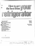
CAUTION
PLEASE READ THIS
MANUAL CAREFULLY
Model
Model
Model
Model
Model
139.53315SR ", 1/3HP
139.53415SR1/2HP
139.53615SR = 1/2HP
139.53625SR - 1/2HP
139.53699SR _ 1/2HP
FASTEN THIS MANUAL NEAR THE GARAGE DOOR AFTER
INSTALLATION,
PERIODIC
CHECKS
OF THE OPENER ARE
REQUIRED
TO INSURE SATISFACTORY OPERATION.
FOR RESIDENTIAL
,
,=
,=
USE ONLY,
,,NIU =
I
,
, I ............................
CONTENTS
Safety Rules ...................
Operation of Your Opener .......
Maintenance Schedule .........
Features of Your Opener ........
Specifications .................
Accessories ....................
Carton Check List ..............
You'll Need Tools ...............
Assembly ......................
Installation Information
.........
Installation
...................
Force & Limit Adjustment
........
Safety Reverse Test ............
SettingtChanging
Code .........
Having a Problem ? ..............
Repair Parts, Rail Assembly
......
Repair Parts, Installation ........
Repair Parts, Chassis Assembly..
How To Order Repair Parts ......
Maintenance Agreements ........
Sears Warranty .................
PAGE
2
3
3
4
4
4
5
5
6
9
10
17
18
19
20
22
22
23
24
24
24
Start By Reading These important Safety Rules
, H,,,,,,,,,,,,I, JL
,
=
'
'
L
L==
,===1,,, =,, H NH,,=
,,
THIS SAFETY ALERT SYMBOL MEANS CAUTION _-- PERSONAL
SAFETY
DAMAGE INSTRUCTION,
READ THESE INSTRUCTIONS
CAREFULLY,
OR PROPERTY
THIS GARAGE DOOR OPENER IS DESIGNED
AND TESTED
SAFE SERVICE PROVIDED
IT IS INSTALLED
AND OPERATED
WITH THE FOLLOWING
SAFETY
INSTRUCTIONS°
TO OFFER REASONABLY
IN STRICT ACCORDANCE
FAILURE TO COMPLY WITH THE FOLLOWING
INSTRUCTIONS
PERSONAL
INJURY OR PROPERTY
DAMAGE°
MAY RESULT
,
= H,,
,,,,
= H,...,.
,,,,,,.,,
H H,,,,,
H,,
,,.
,J
IN SERIOUS
J N ,,,,
CAUTION: IF YOUR GARAGE HAS NO SERVICE ENTRANCE DOOR, INSTALL MODEL 53702 EMERGENCY RELEASE
KEYLOCK (PAGE 4). THIS ACCESSORY ALLOWS MANUAL OPERA"['ION OF GARAGE DOOR FROM OUTSIDE IN CASE
OF POWER FAILURE.
KEEP GARAGE DOOR BALANCED. Sticking or
binding doors must be repaired. Garage doom,
door springs, cables, pulleys, brackets and their
hardware are under extreme tension and can
cause serious
personal
injury. DO NOT
ATTEMPT TO LOOSEN, MOVE OR ADJUST
THEM. Call a garage door serviceman.
THE SAFETY REVERSE SYSTEM TEST IS VERY
IMPORTANT (page 18). Your garage door MUST
reverse on contact with a 1_ obstacle placed on
the floor. Failure to properly adjust the opener
may result in serious personal injury from a
closing garage door. REPEAT THE TEST AT
LEAST ONCE EVERY THREE MONTHS AND
MAKE NEEDED ADJUSTMENTS.
DO NOT WEAR RINGS, WATCHES OR LOOSE
CLOTHING while installing or servicing a garage
door opener.
Fasten the CAUTION LABEL adjacent to Lighted
Push Button as a reminder of safe operating
procedures.
To avoid serious personal injury from entanglement, REMOVE ALL ROPES CONNECTED 10
THE GARAGE DOOR before installing the
garage door opener.
DISENGAGE ALL EXISTING GARAGE DOOR
LOCKS to avoid damage to garage door.
Install Lighted Push Button (or any additional
push buttons) IN A LOCATION WHERE THE
GARAGE DOOR IS VISIBLE, BUT OUT OF THE;
REACH OF CHILDREN.
DO NOT ALLOW
CHILDREN TO OPERATE THE WALL PUSH
BUTTON(S ) OR TRANSMITTER.
Serious
personal inlury from a closing garage door may
result from misuse of the opener.
Installation and wiring must be in compliance
with your local building and electrical codes.
CONNECT THE POWER CORD ONLY TO A
PROPERLY GROUNDED OUTLET.
CAUTION: Activate opener only when the door
is in full view, free of obstructions and opener
is properly adjusted° NO ONE SHOULD ENTER
OR LEAVE THE GARAGE WHILE DOOR IS IN
MOTION. DO NOTALLOW CHILDREN TO PLAY
NEAR THE DOOR.
LIGHTWEIGHT FIBERGt.ASS, ALUMINUM AND
STEEL DOORS MUST BE SUBSTANTIALLY
REINFORCED TO AVOID DOOR DAMAGE. (See
page 153 The best solution is to check with your
garage door manufacturer
for an opener
installation reinforcement kit,
Use the emergency release ONLY to disengage
the trollcy and, if possible, ONLY when the door
is closed. DO NOT USE THE RED EMERGENCY
HANDLE TO PULL DOOR OPEN OR CLOSED.
DO NOT USE THE FORCE ADJUSTMENTS TO
COMPENSATE FOR A BINDING OR STICKING
GARAGE DOOR° Excessive force will interfere
with the proper operation of the safety reverse
system or damage the garage door (page 17)_
DISCONNECT ELECTRIC POWER TO GARAGE
DOOR OPENER BEFORE MAKING REPAIRS OR
REMOVING COVERS.
O Serat,on of Your Opener
BEFORE
YOU PROCEED, PLEASE READ THE
SAFETY RULES ON PAGE 2 AND OPERATING
INSTRUCTIONS ON THIS PAGE CAREFULLY.
TO AVOID DIFFICU/L,TY DURING INSTALLATION, DO
NOT RUN OPENER UNTIL INSTRUCTED TO DO SOs
e DO NOT PERMIT CHILDREN TO PLAY IN DOOR
AREA.
e OPERATE ONLY WHEN OPENER IS PROPERLY
ADJUSTED AND THE DOOR IS VISIBLE AND
UNOBSTRUCTED.
USING THE OPENER
WHEN OPENER tS ACTIVATED:
Your opener can be activated by any of the following devices:
1_The 3-Function Transmitter. Hold the LARGE push button down until the door starts to move..
1. If open, the door will close, if closed, the door will open
2. If closing, the door will reverse
3- If opening, the door wiFIstop (allowing space for entry and
exit of pets and for fresh air)
4o If the door has been stopped in a partially open position,
it will close.
2_ The Well Push Button° Hold push button down until the
door starts to move.
3. The Key Switch or Touch Code Transmitter accessories°
Described on page 4
OPENING THE DOOR MANUALLY
THE DOOR SHOULD BE FULLYCLOSEDIF POSSIBLF.LWEAK OR
BROKEN SPRINGS COULD ALLOW AN OPEN DOOR TO FALL
RAPIDLY_PROPERTYDAMAGEOR SERIOUSPERSONAL INJURY
COULD RESULT.DO NOT USE EMERGENCYHANDLE TO PULL
DOOR OPEN OR CLOSED.
The door can be operated manually by disconnecting it from
the opener. Pull down sharply on the red emergency release
handle and lift the door manualty.. To automatically reconnect
the door to the opener, press the Wall Push Button.
LOCKOUT FEATURE: prevents trolley from reconnecting
automatically, If you need to use this feature, pull emergency
handle down and back (toward the opener)_Trolleywill remain
"Lock, d-Out" and door can be raised and lowered manually.
To reconnect trolley, pull emergency handle straight dowm
5. If an obstruction is encountered while closing, the door will
reverse.
84 If an obstruction is encountered while opening, the door
will stop
7- If the optional 'infrared Sensor' is installed, the garage door
will reverse in the closing cycle when the invisible beam
is broken. An open door will not close when beam is broken.
The sensor has no effect in the opening cycle.
OPENER LIGHT will turn on under the following conditions:
when the opener is initially plugged in; when the power is
interrupted; when the opener is activated. It will turn off automatically after 4_,_ minutes. Bulb size 75 watts maximum.
CARE OF THE OPENER
When properly installed, opener will l:_OVidehigh performance
with a minimum of maintenance, The opener does not require
additional lubrication.
Most complaints of unsatisfactory opener operation can be
traced to problems with the door itself. When operated
manually, a properly balanced door will stay in any point of
travel while being supported entirely by its springs.
THE OPENER IS NOT INTENDED TO CORRECT ANY
PROBLEMS THAT ARE CAUSED BY AN UNBALANCED OR
BINDING DOOR, BROKEN DOOR SPRINGS OR BY FAULTY
DOOR HARDWARE.
LIMIT AND FORCE ADJUSTMENTS: These adjustments
must be checked and progedy set when opener is installed,
Only a screwdriver is required. P,_ge 17 refers to the limit and
force adjustments. Follow instructions carefully.
REPEAT SAFETY REVERSE TEST AFTER ANY ADUSTMENT OF FORCE AND/OR LIMITS. Weather conditions
may cause'some minor changes in door operation requirIng some readjustments, particularly during the first year
of operation.
THE SAFETY REVERSE SYSTEM IS IMPORTANT (See
Wpg,18). GARAGE DOOR MUST REVERSE ON CONTACT
ITH A ONE-INCH OBSTACLE PLACED ON THE FLOOR.
FAILURE TO PROPERLY ADJUST OPENER MAY RESULT
IN SERIOUS PERSONAL INJURY FROM A CLOSING
GARAGE DOOR.
MAINTENANCE
AT LEAST 4 'TIMES A YEAR
MANUALLY OPERATE DOOR. If it is unbalanced or binding,
call for professional garage door service.
CHECK TO BE SURE DOOR OPENS & CLOSES FULLY.
Adjust Limits and/or Force if necessary.
REPEAT SAFETY REVERSE TEST_ Make any necessary
adjustments (see page 18).
CHAIN TENSION ADJUSTMENT: After installation of the
opener and adjustment of forces and limits, the chain may
appear loose. This is normal, To check the chain tension:
disconnect the trolley by pullingthe red emergengy handle.
If the chain returns to the position described and illustrated
in Step 5 page 9, DO NOT make ANY further adjustmants_
TRANSMITTER: The 3-functiontransmitter willoperate more
than one garage door opener, if desired. The push buttons
may also be used to operate other 53000 and/or53000SR
Series devices. The standardtransmitter may be secured to
car sun visor with clip provided. Additional transmitters can
be purchased at any time_Refer to Accessories on page 4.
Any new transmitters must be set to the same code as the
original transmitterand receiver. Page 19 explains how to
change your existing code and use the transmitter(s) with
other 53000 end,or 53000SR Series receivers_ Self service
of your radio controls is not recommended. If service is
needed, contactyour nearest Sears Service Center.
TRANSMITTER BATTERY: The 12 Volt battery should
producepower for at least one year. As long as the battery
power is adequate, the transmitter test light will glow when
the push button is pressed (and the opener or other control
will operate), tf light doesn't come on, replace the battery. If
transmission range lessens, check battery test light.
TO CHANGE BATTERY: Slidethe battery compartment cover
down (or remove cover screw). Position new 12Volt battery
as directed.
OF YOUR OPENER
TWICE A YEAR
CHECK CHAIN TENSION.
Adjust if necesseryr
ONCE A YEAR
OIL DOOR ROLLERS, BEARINGS
AND HINGES.
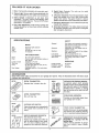
1, Motor: Permanently
lubricated
with automatic
reset.
5. Digital Radio Controls:
changed by the owne_:,
2., Opener Light: Turns on and off automatically with 4¥2
minute illumination for your safety and convenience
7. Emergency Disconnect:
manual door operation.
4. Easy Limit Adjustment:
Limits of door opening and
closing adjusted by turning screws without removing
chassis cover.
iiill
Ulll
Type
Speed
Volts
Ct,_rrent
Permanent split capacitor
1500 rpm
t20 Volts AC - 60 Hz= Only
4,5 amperes
Electronic
........
Electrica!
........
t6:l worm gear reduction
Chain & cable with two-plece trolley on
steel Tee-rail
Adjustable to 71/2 feet
6 to 8 inches per second
, On when door starts in travel, off 41/2
minutes after stop,
Adjustable door arm. Puti cord trol!ey
release
DIMENSIONS
Length (overafl) ....
Headroom required
Hanging weight
.
i
,lu
,i,
permits
Push button and automatic reversal in
down direction. Push button and Auto.
matic stop in UP direction
independent UP and DOWN force adjustment screws
Motor overload protector &iow voltage
push button wiring
Circuit actuated by limit nut
Screwdriver adjuslment on side panel
Low voltage push button or radio
control
Limit device ....
Limit adjustment
Start circuit ......
DRIVE MECHANISM
i
Pull cord disconnect
SAFETY
........
MOTOR
Door finkage
be easily
..........
Personal
Length of travel
Travel rate
Lamp
can
8. Automatic Reconnect: The trolley halves reconnect
for automatic operation when the opener is energized
after emergency disconnect
SPECIFICATIONS
Gears
Drive
code
6. 3-Function Transmitter: Has three push buttons Each
button can activate one or more Light Control and,or
garage door opener. The opener receiver is factory
preset to activate with LARGE transmitter push button,
& Safety System:
Independent
up and down force
adjustment, The door reverses automatically
when
obstructed in DOWN direction The door STOPS when
obstructed in UP position
rill
The
i
u
i i i i,,i J_llllt,l,,
tutl=l
I
I
I I
t24 inches
2 inches
32 pounds
i
,J,l,llll lU,JiJ,ii
..............
, ..........
...I
ACCESSORIES
Sears offers many useful accessories
numbers and descriptions.
for your garage
They are illustrated
door opener.
u U,lll
53778
EXTRA TRANSMITTER:
!
Standard
size. Includes
i i
53710
¢.
"
visor clip.
53758
0
EXTRA TRANSMITTER:
53717
Mini, with key ring.
,i
below
with Sears stock
nlll, .....................................
INFRARED REVERSING SENSOR:
An optional system which provides
i auxiliary support to the safety features
built into your opener,, If the system's
t
inws_ble beam is broken, a closing
i door will reverse and an open door will
not close.
OPEN DOOR INDICATOR:
Provides an illuminated signal when
your garage door is open.
OUTDOOR
KEY SWITCH:
Opens the garage door automatically
from outside when transmitter is net
handy.
TOUCH CODE TRANSMITTER:
Enables homeowner to operate garage
door opener from outside by entering
code en specialty designed keyboard
DOOR CLEARANCE BRACKETS:
(For Sectional Doors Only)
53709
2i7
i
Y
Replace top brackets and rollers on
door to reduce height of door travel.
For use when installing opener in
garage with low headroom clearance.
4
EMERGENCY RELEASE KEYLOCK
REQUIRED for a garage with NO
service door.,
Allows manual operation of garage
door from outside in case of power
failure.
mi
................................
,
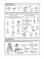
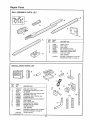
CARTON
CHECK
......... _ 1,1,1
ii
nl
SEARS has packaged your GARAGE DOOR OPENER
illustrated below and on Page 22.
Rag
Grease
Cover
SEPARATE
ii,
ii
nnll
u,i
,i
i,
lul,,
u¸
i
ul
ii
ii
i,!
i
i,i,
LIST
ALL HARDWARE
ASSEMBLY
in two cartons
Lighl
Lens
FOR ASSEMBLY
which contain
Transmitters (21,
exce._ 53415, 53315
& 53899 (1 only)
Touch Code
Tr',.msmitter
13953625 ONLY
AND INSTALLATION
PROCEDURES
INSTALLATION
HARDWARE
all the parts and hardware
Mini
Transmitlet
13g 53699 ONLY
AS SHOWN
BELOW.
HARDWARE
ii(iii-(((!ilfiii(ii I!'t (©
Threa_ed T¢oliey Rod
Clevis Pin
(.t)
5116"
x 2_3/4"
Carriage Bolt
5/16"-1B
x 2-!12 _
(2)
Ring
Fastener (3)
Lockwashe_'
5,'_6"(4)
(_
Rope
Washered Screw
5/16"- 18 x 112"
Master Link
{2)
"(mounted
in chassis)
_
121
N16"
- 18
(5)
lt4"
- 20 x 1/2"
(4) Bolt
Carriage
Hex Screw
Q
&_16" - 18 x 7/8"
(3)
L_)ckNut
1/4" - 20 x 112"
(41
•
unrl,lrlt II,
Jul,i,
,,in,,
i,i
In
U
i
i
u
i,i1,1
ii
i
n
i,i
i
ilul
ilu
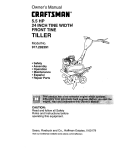
YOU'LL NEED TOOLS
During assembly and Installation of your opener, the instructions will call for the use of various hand tools. Have a
stepladder handy, and those tools illustrated below; hammer, electric drill (& 3116"and 5/16"dr111bits), screwdriver,
adjustable end wrench or socket wrench kit, wire cutters, tape measure, pliers and hack saw.
P_iers
Hack Saw
Tape Measure
Wire Cutters
Claw Hammer
Screwdriver
S[epladder
Adjustable End W_er_ch
Assembly
TO AVOID INSTALLATION
DIFFICULTIES,
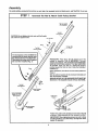
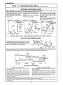
STEP 1
J=
=
= ,=,,H
DO NOT RUN THE GARAGE DOOR OPENER UNTIL INSTRUCTED
Assemble
= H H= ,,,, u,,,,,,,,,, , =J,,,,,
Tee Rail & Attach
, ,,
,,,,,
='==
=,= =,,,,,,,, ,i
TO DO SO.
Cable Pulley Bracket
,,,
,,,=
!
CAUTION: Do not tighten the lock nuts until bolt necks
ate seated in square holes,
_14"Lm_kNut
The end sections of the rail MUST be
connected to the center section from
the direction shown in the illustration,
Otherwise, the trolley will hit against
the nut when installed (Pg. 7).
PROCEDURE: Place the 3 Tee ral! sections on a fiat
surfac_ for assembly. THIS IS IMPORTANT. The end
sections are identical. THE CENTER SECTION BRACES
MUST BE POSITIONED AGAINST THE END SECTIONS
AS SHOWN° Make sure that the "directional arrow"is
pointing toward the fTont (to door)_ Study the illustration
CAREFULLY.
(When assembled,
Tee rail has a front-to-back position as
shown.)
Bolt rail sections together with the hz_lware illustrated and
from Ihe direction indicated.
SQUARE NECKS ON THE CARRIAGE BOLTS MUST BE
SEATED IN THE SQUARE HOLES IN RAIL SECTIONS.
Tea P_t
(End Section)
FRONT
(TO DOOR)
Position the cable pulley bracket on front end of tee rail
as shown. Fasten securely with the hardware provided,
IMPORTANT: When tightening screws, be sure to keep
bracket parallel to rail. Otherwise, rail m_rf bow when
opener is operated.
=
ii ii
,
6
i
i ii1,111111,1=11
ii
iflll
iii
i
ii
............
Assembly
i
iiii
n ,1,1,
i,
i,
i
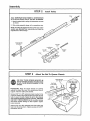
STEP
Ul
AS A TEMPORARY
2
illUU,,lll
ii ,uu,
,,11u11,,i
null
,
Install Trofley
11111J,Ul
i
iiii
ii
I,,llLJ
I u
I
STOP, INSERT A SCREWDRIVER
T,oHE
y%.,f_.,_
_,_
INTO HOLE IN FRONT END OF TEE RAiL AS SHOWN.
asshown
1, At_ch threaded shaft to trolley with tockw_her
_----_
.fr"
and nuts
2. Slide trolley assembly along rail to screwdriver stopo
NOTE: If trolley hits against the nut on Tee rail, center
section was attached from wrong side and must be
re_sitioned.
Review Step t.
Temporary
Stop
.._,_
,uu,
i
iiii
../,'-._j_
_
_
in,,
,
ilU
n
ii,u,,,,,,
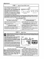
STEP 3
i,i
_"
I
SJJ
i,i................
i
-
J'-_
TtoHey
.................
,," __
._f"
_SJ
_
i
J_J"_
.-"
_
i,n
Attach
i
iii i,
i1,,1!
tl,llll_lll
,,
Tee Rail To Opener
i,ii, ii
USE ONLY THOSE SCREWS MOUNTED IN
TOP OF OPENER CHASSIS. FAILURE TO DO
SO WILL CAUSE SERIOUS DAMAGE TO THE
OPENER.
PROCEDURE: Place the opener chassis on packing
material to protect the cover, For convenient,
place a
support under the cable pulley bracket.,
Remove 5/16"-18 x 1/2" w_hered screws mounted in top
of opener chassis. Align holes in back end of Tee rail with
holes in opener chassis. Fasten the _il to the chassis
with washered screws p_viously removed, CAUTION;
USE ONLY THESE SCREWS! Use of any other screv_
will cau_ serious damage to door opener. Tighten
screws securely°
losert a 5116,-18 x 718" w_hered screw into trolley stop
hole in the Tee rail _ shown. Tighten securely with a 5116"
loc_asher and nut.
IIHII
ii
Chassis
iii
Hex Screw
5/t6"-18x7/8"
Tee Rail
(Back Section)
i
i
,
JiJi u uln.,,,
u,
Assembly
i
i
iii
ii,
iii,
,JIJ,,llJ,lL,II I,,,,,,',,
ii,
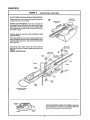
STEP 4
,
iiii
i111
,!l
,i,,,11,,11
i,
Install
Lii
iii ii
i,
ii ,i
i
_11
ii1
Chain and Cable
iiiiiiiiii
I IIIII
ii III II
ii ,11,111111
Lii
DO NOT REMOVE CHAIN AND CABLE FROM CARTON.
Detach cable from side of carton and fasten to trolley with
a master link from coin envelope,
lnstaI| Chain
inThisI_recl_n
B
OpenerCh_,_s
MASTER LINK PROCEDURE: Push pins of master link
bar through loop of cable and hole in front end of trolley
(A) as shown° Push cap over pins and onto notches. Slide
clip-on spring over cap and onto pin notches until both pins
are locked in place.
Caution: Keep the chain taut while installing to help
prevent kinking.
With trolley against the screwdriver, dispense cable around
pulley. Proceed back around opener sprocket (B_. be sure
sprocket teeth engage chain- and forward to the threaded
trolley shaft (C).
Use second master link to connect the chain to the fiat
end of shaft as shown. Check to make sure chain is not
twisted,
REMOVE SCREWDRIVER.
A
ATTACH SPROCKET COVER TO CHASSIS: Insert back
tab in chassis slot. Then bend cover forward and insert
front tab in slot provided on mounting plate.
P_ate
Tab Slot
.................................
,,,
1111
,
[
H
8
"
,
, _llJ,,,m,,,,
,,1
II I
Assembly
Hit
I
i,
,,i
I III
I
,I,
I
STEP 5
, ,,
Loosen
,
Lock
H,,"H
IIIlllll
II
I
Tighten
I I="=
HI
,
the Chain
,I,,H,,
,
H,,I
and
Cable
..................................
CAUTION:
Tighten
Keep the chain from twisting
turned.
as nuts are
PROCEDURE:
Thread the outer nut toward troltey as
shown. (Loosen inner nut first, if necessary.)
Tension is correct when the chain is approximately
1t2"
above the base of the Tee rail, midway between puIley
bracket and chassis.
Tro({_
To maintain
tightened.
Chin
proper lension, make sure inner nut is re-
Sprocket noise can result
or too tight,
.,-.--- 1/2 Inch
CAUTION:
i
if chain is either
Do not overtighten
Page 3.
the
chain.
too loose
Refer
to
Base of Tee R_I
ASSEMBLY
BEFORE YOU PROCEED
ALL SAFETY RULES.
OF YOUR GARAGE DOOR OPENER
WITH THE INS'I'ALLATION
IS NOW COMPLETE.
OF YOUR GARAGE DOOR OPENER,
BE SURE TO COMPLY WIT_
KEEP GARAGE DOOR BALANCED. STICKING OR BINDING DOORS MUST BE REPAIRED. THE GARAGE DOOR,
DOOR SPRINGS, CABLES, PULLEYS, BRACKETS AND THEIR HARDWARE ARE UNDER EXTREME TENSION
AND CAN CAUSE SERIOUS PERSONAL INJURY. DO NOT ATTEMPT TO LOOSEN, MOVE OR ADJUST THEM°
CALL A GARAGE DOOR SERVICEMAN.
DO NOT WEAR WATCHES, RINGS OR LOOSE CLOTHING WHILE INSTALLING
OR SERVICING A DOOR OPENER.
%
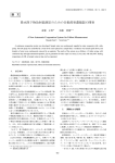
AS YOU PROCEED WITH THE REMAINING INSTRUCTIONS
IN THIS OWNERS MANUAL, YOU MAY FIND IT HELPFUL
3"0 REFER TO THE FOLLOWING ILUJSTRATION OF THE FULLY ASSEMBLED AND INSTALLED GARAGE DOOR OPENER°
:
...............iii1,_
,i
H
N HHHI
llJ,ll,I,
.................................
HI H
HI,HHI
Power Cord
Light
Lens
Arm
O
Eme_ency
Trolley
Release
oDoor
O
Chessis
Curved
Door
Arm
....
IS RECOMMENDED
,ll,
ii
ii
i
i
i
,, i i
THAT THE OPENER BE INSTALLED
i i,ii,i
i
i
,
_,ul,,,..,
i i ii
,i
7 FEET OR MORE ABOVE FLOOR WHERE SPACE PERMITS.
CERTAIN INSTALLATION
PROCEDURES
VARY ACCORDING TO GARAGE DOOR TYPES. WHERE THE DIFFERENCES
OCCUR, BE SURE TO FOLLOW ONLY THOSE INSTRUCTIONS
WHICH APPLY TO YOUR DOOR CONSTRUCTION.
installation
i,! ,i
ii,
iiii
i, ,i,,i i,
iiii1,11
i
i
i
Position
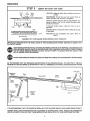
STEP 1
i
, ii
iiii...:: .......
iii
and Instafl Header
iiii L
ii
iiiiiii
,11
iiiii
Bracket
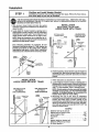
installation procedures vary according to garage door types. Follow only those instructions which apply to your door as tllustratedo
i
i
iii
i
IL
iii
i
....
:=
THE HEADER BRACKET MUST BE RIGIDLY FASTENED TO THE HEADER WALL. REINFORCE THE WALL
WiTH 2x4 IF NECESSARY. FAILURE TO COMPLY MAY RESULT IN IMPROPER OPERATION OF SAFETY
REVERSE SYSTEM (SEE PAGE 18)+
INSTALLATION
SECTIONAL
DOOR AND
l-PIECE DOOR WITH TRACK
1o With the door closed, locate and mark the vertical
centerline of garage door. Extend line onto header wall
above the door.
2. Locate height for header bracket by opening door to
highest point of travel as shown. Draw an intersecting
horizontal line on header wail 2" above high point. This
height provides travel clearance for top edge of door.
NOTE: When the headroom is not sufficient for 2"
clearance, the bottom edge of bracket may be placed
parallel to the high point of travel
ONE-PIECEDOOR
HORIZONTAL TRACK
JAMB HARbWARE
SECTIONAL DOOR
CURVED TRACK
Ceiling
Header
_cket
Door Clearance Brackets ere designed for low
headroom installations (page 4). They replace top
brackets and milers on the garage door, thereby
lowering the high point of door travel. Installation
instructions are contained in the accessory carton.
{_ackel
Track
. /
i
I"
I
,,_
I .F
3. Position bracket as shown (bottom edge of bracket on
herizortal line). Mark either top and bottom or left and
right bracket holes. Drill 3/16" pilot holes and fasten
bracket.
H_hest
P_nt o!
"Travel
y
ii,J,
/
IIIIL,
i
irlll,lll
ijlll
ii , iii
INSTALLATION
1-PIECE DOOR WITHOUT
ONE PIECE DOOR
..... "NO TRACK
PIVOT HARDWARE
Header
i ,,,i
iiiiii1,1111
,i
ii
i
r
i
i
ir
t. Follow instructionsas described
in 1 above.
TRACK
2. Locate height for header bracket by opening doot: to
highestpoint oftravelas shown.Measure the distance
from top of door to floor, Subtractactual height of door.
Add 8" tothe remainder.Refer to examplebelow.
NOTE: If total number of inches exceedsthe height
available in your garage, use the maximum height
possets. On finished ceilings, do not position the
bracket closer than 1/2" from ceiling.
3 Measudng frem top of door draw an intersecting
horizontal
line on the headerwallat determinedheight.
Position the bottom edge of header bracket on the
horizontal line, centeringbracket on verticleline, Mark
either top and bottom or left and right holes°Drill 3/16"
pilot holes and fasten the bracket with 5/16"xl-7/8" lag
screws as shown above,
ONE PIECE DOOR
NO TRACK
JAMB HARDWARE
HighestPo{nt
of Trey!!
Door
EXAMPLE
Distance from lop of door (at
highest pointof travel) to floor ................. 92"
Actual height of door ........................
88"
Remainder ................................. 4"
Add ........................................
+ 8"
Bracket height on header wall ................
(Measure UP from top of doer
in closed position.)
i
i
ii
10
i,i
i
,11.,.,,
i
.
12"
|n3tallation
....
ii H
i ml
,i
ii
ill
ii
STEP
,
_
,,,
2
,, .............
Attach
,
i!
i
i
nl
Tee Rail to Header
I,,,IL
,i,n
i,,,i,i,
Bracket
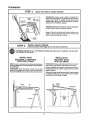
PROCEDURE: Position opener chassis on garage floor
below the header bracket, Use packin 3 matedaI base to
protect cover° NOTE: To enable the Tee rail to clear
sectional door springs, it may be necessary to lift the
chassis onto a temporary support,
CAUTION: Chassis must either be secured to support
or held firmly In place by another person.
Raise the Tee rail until pulley and header brackets come
together. Align bracket holes and join with clevis pin as
shown,, Insert ring fastener to secure°
Pac_king
M.atedal
in
H
h
"
IIIIIII
IIIII
,IlL
I
STEP 3
I' I'1
UH
Position
II
Opener
Follow instructions
iiiH
lille
II
, iiiiii
I,HIIrll
I I,I,
,I
II Illu,_
Chassis
which apply to your door type as illustrated.
I iHililflilli
TO PREVENT DAMAGE TO ALL LIGHTWEIGHT
THE OPENER ON THE DOOR_
I
li
i
ili'
i
i i
'
i
I
DOORS AND DOORS WITH WINDOWS,
INSTALLATION
SECTIONAL
& ONE-PIECE
DOOR WITH TRACK
ii
..........
DO NOT REST
INSTALLATION
ONE-PIECE DOOR
WITH NO TRACK
PROCEDURE: Measurethe distance from floor to top of
door (in fully open positionand parallel to the floor),
Using a stepladderas a support,raise opener chassis to
the same distancefromthefloor (chassiswill have a stight
angle as shown).
The top of the doorshould be level with the top of opener,
For maximum efficiency, do not position opener chassis
more than 2 inches above this point.
NOTE: A 2x4 is convenient for setting an ideal doorto-Tee rail distance, tt is not necessery where headroom
ts Insufficient.
PROCEDURE: Raise the opener chassis onto a stepladder, Open garage door, Place a 2x4 on top section of
door near centedine as shown below, Rest Tee rail on 2x4°
Top of Opener
in,i
11
.
ill i,
lul
Hn ,i I,HI
..............
i
.....
In.otallation
.,,,,,,,
,
STEP
THE OPENER
CHASSIS
4
i
ii ,11,1,!
Hang
,11
Opener
MUST BE SECURELY FASTENED
i,,
N,
i1,,
, ,,,,
i
,,,,,
Chassis
TO A STRUCTURAL
SUPPORT OF GARAGE.
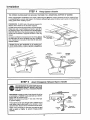
Three representative installations are shown. Yours may be different. Hanging brackets should be angled (Fig.l)
or crossed (Fig.2) to provide rigid support, On finished ceilings (Fig.3), attach a sturdy metal bracket (not supplied) to
ceiling joists before installing opener.
PROCEDURE:
On EACH
side structural
of the opener
measure the
distance from chassis
to the
supports,
_..,._...._._
_
FtGU_E2
Ratten one end of each bracket and bend or twist to fit
_'--_
the fastening angles, Do not bend at the bracket holes.
Drill 3/16" pilot ho_es in the structural supports. Attach flatCut
tened
both
ends
pieces
of brackets
of the hanging
to supports
bracket
with
to 5/16"
required
xl-7/8"
lengths,
lag
_-----_-....,._
screws°
Lift opener and fasten to hanging bracket as shown. Check
to make sure Tee rail is centered over door. REMOVE
2X4o Operate door manually. If door hits the rail, raise
header bracket,
sl _he_,
'" "_N_'_
_._._
__._
"*_-"
_ __
]
Grease trolley
the top
and Aunderside
of rail issurface
on |
which
slides.
tube of grease
supplied.
Bracke[
(Not Supplied)
H ,,,,f,,,i
i i,,
.................
,,
STEP 5
iii
FIGURE 3
i
i
i
MI
ii
Attach
II
I
I,III
Emergency
I
III
IIIII1,1111
Release
II
FINISHED
CEILING
H
i,,,
iii1, i
Rope & Handle
I_
.......ii
USE EMERGENCY RELEASE ROPE ONLY TO
DISENGAGE TROLLEY. DO NOT USE ROPE
AND HANDLE TO PULL THE DOOR OPEN OR
CLOSED,
PROCEDURE: Thread one
of red handle so 'NOTICE'
Secure with an overhand
NOTE: Knot should be at
to prevent slipping.
end of rope through hole in top
reads right side up as shown_
knot°
least 1" from end of the rope
Thread other end of rope through hole in release arm of
outer trolley. Adjust rope length so that handle is 6 feet
above the floor. Secure with an overhand knot as above.
Rope
NOTE: If it is necessary to cut rope, heat seal cut end
with a match or lighter to prevent fraying and/or
raveling.
Overha_
Release Arm
G
..................................
,!,l ¸,
12
H,I
i,
i i
/,,
_---R
Emergency
elease Handle
installation
i,
u,,,,
i,,,.
i,
,u
i
STEP 6
Install
Waft Push Button
i
i
i,
i,
ii ii
,,11
nl,
liH,m
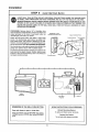
LOCATE WALL PUSH BUTTON (OR ANY ADDITIONAL PUSH BUTTONS) WHERE THE GARAGE DOOR
IS VISIBLE, AWAY FROM DOOR AND DOOR HARDWARE AND OUT OF THE REACH OF CHILDREN, "
SERIOUS PERSONAL INJURY FROM A MOVING GARAGE DOOR MAY RESULT FROM MISUSE OF THE
OPENER. DO NOT ALLOW CHILDREN TO OPERATE WALL PUSH BUTTON(S) OR THE TRANSMITTER,
FASTEN THE CAUTION LABEL ON THE WALL NEAR WALL PUSH BUTTON AS A REMINDER OF SAFE
OPERATING PROCEDURES
PROCEDURE: Remove about a 114" of insulation from
each end of the 2-strand bell wire. Connect one end to the
screw terminals on the back of wal! push button (or
doorbell-type push button) as shown.
Fasten the wall push button with 6ABxl" sheet mete}
screws, The doorbell4ype push button has 6ABxl-1/2"
sheet metal screws, Use anchors if attaching to dry watlo
Install on an inside garage deor A convenient place is
side the _i_
_r and OUT OF REACH OF CHILDREN.
DOOR BELL-TYPE
LIGHTED PUSH BUTTON
WALL PUSH BLrTTON
Terminal
Screws
Top Installation
Flange
Run the belf wire up the wall and acres the ceiling to the
garage d_r o_ner. Secure with insulated stapEes,
The receiver terminals and the antenna are located on the
back panel of the opener chassis F_sition antenna wire
as showm Then cennect the wire by color to the white and
red o_ner terminal screws,,
Terminal Screws
Borlom In s_allation
Flange
Opener
Terrn_n,ld Screws
Ughted
Pushbut_on
Rear P a,,lel
of Opener
OPERATION OF THE WALL PUSH BUTTON
WIRING INSTRUCTIONS
Infrared
Press and release to open or close door.
lll
Reveming Sensor:
To white and black opener terminals
Press and rele_
again to REVERSE door during
CLOSING cycle or to STOP door during OPENING
cycie.
i
FOR ACCESSORIES
Outdoor Key Switch:
To red and white opener terminals
i
ii
13
iiiii,!l
Ill,
Illl
ulull,_
nL
]nstaliation
ILLII
II
I
II
,_l!l,,
I
STEP 7
...............ii
INSTALLING
ll,,
ill
II,I,
I,,
Install
i
I,,,,
I
I
Ill
Light and Lens
,,
i
,
i,i
,i
,,i
LIGHT:
Install a 75 watt maximun light bulb in socket as shown°
The light will turn on and remafn lit for 4-1/2 minutes when
power is connected,, After 4d12 minutes it will turn off_
If light bulb burns out prematurely due to vibration,
replace with s bulb specifically packaged for "Garage
Door Openers".
INSTALLING
Lens Guide
LENS:
Sllde the lens into the guides as shown, Snap the bottom
tabs into lens stots,
75 Watt Max
Lens Tab
illl
i lll
ii
,,,,,
ii,
ill
HI,
i
iii
H i
i
i
i,ii
iii
H
,i
i
,
i
i,illl i,ill
STEP 8
FI,,
,,,J
i=ll
i,i
i
illlJ
iii
H
ii
•
Connect
i i
Light Bulb
i,i
llJ
i
Electric
i
i
I,H
•
•
Power
ii
TO AVOID SERIOUS PERSONAL INJURY FROM ENTANGLEMENT,
TO THE GARAGE DOOR BEFORE OPERATING OPENER.
!,
i
ii
i
ii
ii
REMOVE ALL ROPES CONNECTED
TO AVOID DAMAGE TO GARAGE DOOR AND OPENER, MAKE DOOR LOCKS INOPERATIVE BEFORE
CONNECTING ELECTRIC POWER. USE A WOOD SCREW OR NA|L TO HOLD THE LOCKS IN "OPEN"
(UNLOCKED) POSITION.
INSTALLATION & WIRING MUST BE IN COMPLIANCE WITH LOCAL ELECTRICAL AND BUILDING CODES.
OPERATION AT OTHER THAN 120V 60Hz WILL CAUSE OPENER MALFUNCTION
Opener MUST be permanently wired or plugged into a
grounded 3-prong receptacle wired according to local etectrical codes. DO NOT use a 2-wlre adapter. DO NOT use
an extension cord°
AND DAMAGE.
PERMANENT WIRING
CONNECTION
Ground Tab
Green Ground
RIGHT
Wire
(Ground)
WRONG
IF LOCAL CODES REQUIRE PERMANENT
WIRING:
DISCONNECT THE POWER AT THE FUSE
BOX BEFORE PROCEEDING.
PROCEDURE: Refer to [llustratiom Make connection
through the 7/8" diameter hole in top of opener chassis°
White
Wire'
'
1. Remove opener chassis cover by removing the cover
screws
CAUTION: BE SURE THAT THE UNIT IS GROUNDED
ACCORDING TO LOCAL CODE.
2, Remove attached 313rong cord.
& Connect the black (line) wire to black wire on terminal
block; whtta (neutral) wire to the white terminal wire;
tim green (ground) wire to green ground screw°
IMPORTANT
NOTE:
TO AVOID INSTALLA'rlQN
DIFFICULTIES, DO NOT RUN OPENER NOW.
..............
14
H i
ii,
i i
Installation
H
i,ill
nl
STEP 9
i
i
i ill
ii m,ll,iHii
iH,
i
nl i!................
Instau Door Bracket
Follow instructions
TO PREVENT
DAMAGE
TO LIGHTWEIGHT
PANELS), ALWAYS REINFORCE
THE INSIDE
2x4 BOARDS
OR ANGLE IRON.
,,,
,
rl,
ill,, it i i,u,lll
and Plate
which apply to your door type as illustrated below.
AND METAL GARAGE
DOORS
(OR ONES WtTH
GLASS
OF DOOR--BOTH
VERT1C..ALLY AND HORIZONTALLY--WITH
The horizontal brace should be at least 6 feet long. The vertical brace should cover height of top panel.
with your garage door manufacturer for a door reinforcement kit for an opener installation,,
Sectional
Door Installation
Check
Procedure
1. Assemble door bracket and plate as shown, Center
bracket on previously marked vertical guideline
Header
Bracket
2, Position the bracket assembly on the face of the door
within the following limits:
A) The top edge of the bracket 2"- 4" below the top
edge of the door
B) Directly below any structural support across the top
of the door
Ver,Jca]
CenIer
Line
Placement
depends on your particular
needs
& Mark and drill 5/16" TOP and BOTTOM fastening holes,,
Secure bracket as shown,
Door Bracket &
%,
Door
/
Bracket
"/_a
Door Bracket
Carriage Belt
_(
Plale
Nu!
_!16"-18
of l_r0r o_-Reinlorcement
Board
Washer
_/16"
One-Piece
Door installation
NOTE: Door bracket has left and right side fastening
holes. Assemble and install the door bracket and plate
if your installation requires top and bottom fastening
holes.
I, Center bracket (with or without plate as required) on
top edge of door as shown° Mark holes,
2. Drill two 5116" holes and fasten the door bracket with
hardware supplied
Procedure
NOTE: The door bracket may be installed on face of
door if required for your installation. (Refer to dotted
line drawing,,) HOWEVER, drill 3/16" pilot holes and
substitute 5116"x 1.1/2" lag screws (not supplied) to
fasten the bracket to the doon
ONE PIECE DOOR
NOTE: If the door has no exposed framing, drill 3tt6"
pilot holes and use 5/16" x 1 - 1/2" lag screws (not supplied) to fasten bracket to top of door°
Bracket
_Header
Door
Bracket
Header Walt --
Door
Optional .___
Face of Door
lnstallalion
_
Doo_" Bracket
PIate
(Optional)
nstallation
.......................
,,,.,
STEP
10
Connect
Door
Follow
those
only
H,, ,,,
Arm
sure garage door is closed
trolley back to the center
which
apply
ii
i,,
i,,,
SECTIONAL
Make
outer
u,,...,
,,,
DOOR
,
to your
door
,
,
i
.,.,,,
i,
.
type°
,m
H,,,, ,,, ,t
,
, i
,
INSTALLATION
tighL Pull the emergency
release handle
to disconnect
of inner trolley as shown in Figures
A, B and C.
FIG A: Fasten straight door arm section
to outer trolley with a clevis pin. Secure
the connection with a ring fastener.
Fasten curved section to door bracket in
the same way_
,
to Trolley
instructions
,.,,
,
the trolley..
Manually
move
FIG C: tf holes in curved arm are ABOVE
holes in straight arm, disconnect straight
arm Cut about 6" from the solid end,
Reconnect to trolley with CUT END
DOWN as shown,
FIG B: Bring arm sections together. Find
two pairs of holes that line up and join
sections
Select holes as far apart as possible to
increase door arm rigidity.
Bring arm sections together, Find two
pairs of holes that line up and join with
screws, lock washers and nuts
A
C
Lock
Washers
5/16"
0
Emergency
Reiease
Handle
121
--h.._'.F m_et
H-- Str_gh_
loL
rA,m
_t5"-18x_8"
1"_"_'X,_.._S°._/_'" Curved
C_evisPin _
_
D_or Arm
Proceed
to Step 1, page 17o Trolley will re-engage
ONE-PIECE
DOOR
ASSEMBLE DOOR ARM: Fasten straight and curved door
arm sections together to longest possible length.. With door
closed, connect straight door arm section to door bracket
with a clevis pin. Secure with a ring fastener,
automatically
when opener
is operated.
INSTALLATION
Door
Bracket _
0-----_
Ring
Fastener
-
-
Nuts
o,o,,o ,o
r,tISc_.
ewsz,rt'_.____4_
"" _"___.__
5/16"-18x7/8
"
Before connecting
door arm to trolley, limits of travel must be adjusted
on one-piece
doors. Limit adjustment
are located
on left side panel
as shown
in illustration
on Page 17. Follow procedures
below.
Door Arm
screws
Fully Closed
Trolley
Closed
Door
Open Doer
Deer Arm
Bracke[
Door Arm
!
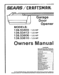
ADJUSTMENT
OPEN
DOOR
CLOSED
ADJUSTMENT
Decrease UP limiL _Jrn UP limit adjustment
wise 4 complete turns.
Press Lighted
PROCEDURES
Wall Push Button.
DOOR
ADJUSTMENT
Decrease DOWN limit. Turn DOWN limit adjustment screw clock _
wise 8 complete turns
Press Lighted Wall Push Button. Trolley wilt travel to full closed.
screw counterclock-
Trolley will travel to rut1 open
Manualfy close door and lift door arm to trolley. The arm should
touch trolley just ahead of door arm connector hole as shown in
dotted line drawing. If arm is behind the connector hole, adjust
timer furthe_ One full turn equals 2" of door travel
Manually raise door arm to open position (parallel to floor) and
lift door arm to trolley The arm should touch t_olley just in back
of door arm connector hoie as shown in solid line drawing. If arm
does not extend far enough, adjust limit further. One lull turn
equals 2" of door travel.
CONNECT DOOR ARM TO TROLLEY: With door closed, join curved arm to connector hole in tro,ey with remaining
with ring fastening pin. NOTE: It may be necessary to lift door slightly to make connection.
Run opener through
is parallel to floo_
a complete
Vavel cycte
I! door has a stight 'downward'
16
slant in full open position,
decrease
clevis pin Secure
UP limits until door
Adjustment
=u
,1,
,u.,imu.
1,
,,,,,1
i i,
STEP 1
ulul
AdjustUP
,
_LL,,II,
IIII
II
and DOWN
'
,,,",
Limits
...........
•
i i,
Ji,
Limil
LIMIT ADJUSTMENT settings regulate the points at which
the door will stop when mowng up or down.
Adjustment
NOTE: Door STOPS in the UP direction if anything
interferes with door travel. Door REVERSES in the
DOWN direction if anything interferes with the door
travel (including binding or unbalanced doors).
PROCEDURE: To operate opener, press wall push button
or transmitter, Run the opener through a COMPLETE
Leit Sid'e Panel
TRAVEL CYCLE, Limit adjustments are not necessa_
when the door opens and closes completely and doesnt
reverse unintentionally in the down position
The following chad outlines adjustment procedures° Run the opener through a COMPLETE TRAVEL CYCLE AFTER
EACH ADJUSTMENT. NOTE: REPEATED OPERATION OF THE OPENER DURING ADJUSTMENT PROCEDURES MAY
CAUSE MOTOR TO OVERHEAT AND SHUT OFF, SIMPLY WAIT 15 MINUTES AND TRY AGAIN. Read chart carefully
before proceeding to Step 2 Use a screwdriver to make limit adjustments,
LIMIT ADJUSTMENT
IF DOOR DOES NOT OPEN COMPLETELY
BUT OPENS AT [.EAST FIVE FEET
CHART
IF DOOR DOES NOT CLOSE COMPLETELY
(ON ONE-PIECE DOORS)
Increase DOWN travaloTurn the down limit adjustment
screw counterclockwise. One turn equals 2" of travel
IF DOOR REVERSES WHEN CLOSING AND THERE
tS NO INTERFERENCE TO TRAVEL CYCLE
Increase UP travel° Turn the UP LIMIT adjustment screw
clockwise, One turn equals 2" of travel•
If door does not open at least 5 feet: adjust OPEN
FORCE as explained in Step 2r
Test door for binding: Full emergency release handle°
Manually open and close doer, If door is binding, call a
door serviceman, If door is not binding or unbalanced,
adjust CLOSE FORCE. See Step 2_
IF OPENER REVERSES IN FULLY CLOSED POSITION
IF DOOR DOES NOT CLOSE COMPLETELY
(ON SECTIONAL DOORS)
Increase DOWN traveLTurn down limit adjustment screw
counterclockwise. One turn equals 2" of travel
If the door still will not close completely, the header bracket
is positioned too high. Repeat Step 1, page 10
Decrease DOWN travel Turn down limit adjustment screw
clookwise_ One turn equals 2" of travel,
, UiHliH,
STEP 2
,
UH,,
Hi,
I
Adjust Force
EXCESSIVE FORCE WILL INTERFERE WITH PROPER OPERATION OF SAFETY REVERSE SYSTEM OR
DO
NOTuSE
FORCEDOOR.
ADJUSTMENTS TO COMPENSATE FOR A BINDING OR STICKING _RAGE
DooR,
DAMAGE
GARAGE
Force Adjustment Controls are located on rear panel of
opener. FORCE ADJUSTMENT settings regulate amount
of the power required to open and close door.
Force
Adjustmenl
NOTE: The door STOPS in the UP direction if anything
interferes with Its travel. Door REVERSES In the DOWN
direction if anything interferes with its travel (including
binding or unbalanced doors),
If the force adjustments are set too light, door travel may be
interrupted by nuisance reversals in DOWN direction and
steps in UP directionr As weather conditions can affect the
door movement, occasiona! adjustment may be needed.
Maximum force adjustment range is 260 degrees, about
3/4 of a complete turn° Do not force controls beyond that
point° Turn force adjustment controls with a screwdriver.
Adjustment,
FORCE ADJUSTMENT
u_u,,,
L
,11, =,
,,,
J 1,=,
,1,=
CHART
IF DOOR DOESN'T OPEN AT LEAST 5 FEET
Increase UP (OPEN) FORCE by turning control clockwise.
Make 10 degree turn adjustments
until door opens
completely. Readjust UP LIMIT if necessary. After each
adjustment, run opener through a complete travel cycle.
TEST DOWN (CLOSE) FORCE
Grasp the door handle or door bottom when door is about
halfway through DOWN (CLOSE') TRAVEL Door should
reverse. If the door is hard to hold or doesn't reverse,
decrease DOWN (CLOSE) FORCE by turning the control
in a counterclockwise direction. Make 10 degree turn
adjustments
until door reverses normally. After each
adjustment, run opener through a complete cycle.
PROCEED
TO STEP 3
,,H
Label
i,,
17
IF DOOR REVERSES DURING DOWN (CLOSE) CYCLE
Increase DOWN (CLOSE) FORCE by turning the control
clockwise, Make 10 degree turn adjustments until door
completes close cycle. After each adjustment, run the
opener through a complete travel cycle.
uip,
,
,
..................................
Adjustment
..........
irll
STEP 3
ii
...............................
TestSafetyReverse System
ii IIIIIL
i
ii
THE SAFETY REVERSE SYSTEM TEST IS IMPORTANT. GARAGE DOOR MUST REVERSE ON CONTACT
WITH A ONE INCH OBSTACLE PLACED ON THE FLOOR. FAILURE TO PROPERLY ADJUST OPENER MAY
RESULT IN SERIOUS PERSONAL INJURY FROM A CLOSING GARAGE DOOR. REPEAT TEST AT LEAST
FOUR TIMES A YEAR AND ADJUST AS NEEDED.
PROCEDURE: Place a 1-inch obstacle on the floor under
the garage door° Operate door in DOWN direction. The
door MUST reverse on the obstruction°
SECTIONAL
DOOR
If the door STOPS on the obstruction, it is not traveling
far enough in the DOWN direction. Increase the DOWN
limit by turning DOWN limit adjustment screw counterclockwise 1/4 turn. REPEAT TEST_
NOTE: Make sum limit adjustments do not force the
door arm beyond a straight up and down position. See
the Illustration on Page 16.
When the door reverses on the l-inch obstacle, remove
the obstruction and run the opener through a comptete
travel cycle. Door MUST NOT reverse in c!osed position.
if it does, repeat Adjustment Steps 1, 2 and 3_
ONE-PIECE DOOR
I InertC_s,_'uctlon
REPEAT ADJUSTMENT
e
e
e
e
...............
i
ii
J
i
i,,11 i_
LI iii
iii
i,iii
ii
i
STEP 4
(Optional)
......
STEP 3 AFTER:
EACH ADJUSTMENT OF DOOR ARM LENGTH, CLOSE FORCE OR DOWN LIMIT,
ANY REPAIR OR ADJUSTMENT OF GARAGE DOOR (INCLUDING SPRINGS AND HARDWARE).
ANY REPAIR OR BUCKLING OF THE GARAGE FLOOR.
ANY REPAIR OR ADJUSTMENT OF THE GARAGE DOOR OPENER.
III,I,IIL
, i
iiii
ii
instafl
.
i
Infrared
i
ii,
,lllll,lllllt iii
i
,i,ii
i1,11 if
Reversing
iii
i
i
Sensor
i,i ....................
i,
The INFRARED REVERSING
SENSOR provides an
ADDITIONAL measure of safety against a small child
being caught under a garage door. It uses an invisible
beam which, when broken by an obstruction, causes a
c!osing door to open and prevents an open door from
closing.
After the garage dooropener has been completely installed
and adjusted, the INFRARED REVERSING SENSOR
accessory can be Installed. Instructions am included with
this optional device.
i
i
i
ii
ii1,1 i, i,
18
ii ,i
i
ii
i, i
iil,.rJ__
i ,11,
.......•
......i
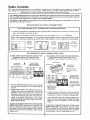
Radio Controls
EC.C. rules prohibit adjustments
to or modification
code setting and replacing the transmitter
battery
Manufactured
under
of receiver and transmitter
THERE ARE NQ OTHER
! or more of the fol_owlng U.S. patents:
circuitry except for changing
the
USER SERVICEABLE
PARTS
RE2g_525; 4,03"7,201; 4,750,1t8;
4,806,930
Your 53000SR SERIES garage door opener (with RECEIVER 'SR' CODE BUTTON) has been factory set to operate
with the LARGE push button on the transmitter, The 3-function transmitter(s)
can also activate additional garage
door openers and/or light controls. 53000 and/or 53000SR SERIES.
Instructions
are given below for matching
transmitter(s)
with other receivers,
the code in all transmitters,
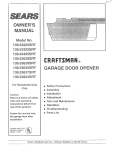
MATCH/CHANGE
THE
changing your code selection
or using the
CODE IN TRANSMITTER(S)
SET CODE SWITCHES IN ALL TRANSMITTERS
TO MATCHING POSITIONS
1. Locate the code switches in transmitter(s), either by sliding batteq/compartment
screw and carefully turning case top overr
cover down or by removing cover
2. With a pen or a screwdriver, change the setting of one or more switch (to a (+), (-) or (0) position).
NOTE: Code switches 2 through g in ALL transmitters used to operate e receiver must be set to match. (Code
switch 1 on a 34unction transmitter
is neutral Set it to ANY position° It will not affect the code selected).
'---
Standard
3*Function
3
"---
3-Function
Mini Transmitter
3_Function
Trat_s miller
Code Switches
] t _"_
....
_-_---.Code
__!i
Switches
,,
SET
RECEIVER
0-9}
Standard
"*-COde
Switches
(2.9)
TO MATCH TRANSMITTER(S)
CODE
53000 SERIES (WITH RECEIVER CODE SWITCHES)
Garage Door Openers and Light Controls
(Illustration B shows a garage door opener receiver)
53000SR
SERIES (WITH RECEIVER
CODE BUTTON)
Garage Door Openers
and Light Controls
(illustration
A shows a garage door opener receiver)
Push Button (-}
3 FUNCTION
TRANSMITTER
Select
a trar_smi[ter
GARAGE DOOR
OPENER RECEIVER
(Wilh SR Code Button)
A
_
push
AE_
burton to operate receiver
v_rr
e,_K
%%%
B
3 FUNCTION
TRANSMITTER
'tEL
%
Select a transmitter
push butlon to operate
receiver
Push Bu_
Push Button (el
YEL
%
SR
tnd[caler
Code Button
Light
GARAGE
DOOR
OPENER
(With
CodeRECEIVER
Switches)
S{ide receiver code
switch #1 to posit.ion
that matches r_e_ected
transmitter push buItoo
(+; 0 or -)
\
3. Press the RECEIVER SR code button on the right side
panel of opener (Illustration A) The indicator light will
turn ON.
Code Switch #t ('l
Receiver wiiI operale
with _ransmitters'
large push butlon
4, STAND AWAY FROM THE DOOR and press the
selected push button on the transmitler The indicator
light will turn OFF and door will move, Receiver and
transmitter codes now match and the opener will
operate with the selected push button on the transmitter,
3 Locate the receiver code switches Set code switch #1
to match transmitter push button you want to use with
that receiver (+), (0) or (-). Refer to illustration (B).
4. Hold a transmitter (with code switches visible) alongside the receiver. Beginning with RECEIVER code
switch #2, match the position of each transmitter
switch,
NOTE: tf transmitter push button is not pressed
within 30 seconds, the indicator light wilt turn OFF.
Begin again at Step 3.
TO USE THE TRANSMITTER(S) WITH OTHER 53000SR
SERIES RECEIVERS: Select another transmitter push
button to operate the Light Control or additional garage
door opener, Make sure all transmitters used to operate
receiver are set to the same code (Steps 1 and 2) Repeat
Steps 3 and 4,
TO USE THE TRANSMITTER(S)
WITH OTHER 53000
SERIES RECEIVERS: Select another transmitter push
button to operate the Light Control or additional garage
door opener. Make sure all transmitters are set to a matching code (Steps I and 2), Repeat Steps 3 and 4
'
,,,,,,u i i
19
, ,,,,,
,i ,,t
,, ii
!taving
a Problem?
Review
SITUATION
PROBABLE
i,,N
i,ii
ii
i
Pages
2 and
CAUSE
3 Before
Proceeding
& SOLUTION
i
OPENER DOESN'T OPERATE
FROM EITHER THE WALL PUSH
BUTTON OR TRANSMITTER
1 Have you disengaged
2
all door tocks? Review Step 8, page 14r
Does the opener have electric power? Plug a tamp into the outiet. If it doesn't
light, check fuse box or circuit breaker (Some outlets are controlled by a wail switch.)
3 Repeated operation may have tripped the overload protector in the motor, Wait
15 minutes Try again.
4. is there a build-up of ice or snow under door? Door may be frozen to ground, Remove any obstruction
5. Remove beIl wire from opener terminals. Short red and white terminals by touching both terminals at same time with a piece of metal (screwdriver or coin) if opener
runs, check for a faulty wire connection at wa)l push button or a short, under stapIes.
................
OPENER
OPERATES
FROM
TRANSMITTER
BUT NOT
FROM WALL PUSH BUTTON
DOOR
WALL
FROM
OPERATES
FROM
PUSH BUTTON
BUT
THE TRANSMITTER
2
NOT
HI
correct?
Review Step 6, page 13.
push button is pressed?
if not,
2
If you have two transmitters and only one operates, review the code setting
procedures on page 19 ALL transmitters must be set to same code.
3
)s transmitter(s) operating any other remote controf devices? See the code setting
procedures on page 19.
Dfd you press the transmitter button designated to operate garage door opener?
5
HAS
Are wiring connections
1 Does the battery test light glow when transmitter
replace the battery
4
TRANSMITTER
SHORT
RANGE
i ,,
1 Is wail push button _it? If not, refer to No 5 above and fo)low same procedure
Reprogram receiver and ALL transmitters. Try setting ALL transmitter code switches
on plus, center or minus positions If transmitter(s) works, you can try a random
code switch setting again, if you desire.
1 Check battery test light. If the light is dim, change the battery
2
Change the location of the transmitter
in the car.
3 A metal garage door or foil-backed insulation or metal siding will reduce the
transmission range Antenna extender kit is available from any Sears Store or
Service Cente[
4
THE
AND
GARAGE
CLOSES
DOOR OPENS
BYITSELF
Check to be sure antenna on the back panel of opener extends fully downward_
1 is there a neighbor with a garage door opener using the same frequency code?
Change your code Review page 19
2. Check to be sure that none of the transmitter ptJsh buttons is stuck in the 'down'
position
3. Remove betl wire from opener terminals and operate from transmitter only, If this
solves the problem, the wall push button is faulty (replace), or there is a short or
broken wire between push button and opener.
DOOR DOESN'T
COMPLETELY
OPEN
1. Is something obstructing
the door?
2. If door opens at least 5 feet, travel limits may need to be increased. One turn equals
2 inches of travel, See page 17,
REPEAT SAFETY REVERSE TEST after the adjustment is complete.
3. If door has been working properly but now doesn't open all the way, increase the
UP FORCE. See page 17.
REPEAT SAFETY REVERSE TEST after the adjustment is complete°
DOOR DOESN'T
COMPLETELY
DOOR
WON'T
CLOSE
CLOSE
"L
IS something obstructing the door?
2. Review the Trave! Limits Adjustment Chart on page 17.
REPEAT SAFETY REVERSE TEST after any adjustment
close force or down limit.
of door arm length,
The Infrared Reversing Sensor (tf you have installed this accessory) may
misaligned or obstructed Disconnect sensor and check door operation. V
problem disappears, correct alignment
2O
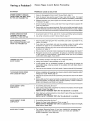
Having
a Problem?
(continued)
SITUATION
,,,
i
PROBABLE
i
i
,i
i
,
I,H,m
Ill
,.,.,I,,,
DOOR REVERSES FOR
NO APPARENT REASON
CAUSE
,..,,m
& SOLUTION
.
,
I,
..,
I
1 Is something obstructing the door? Pull red emergency reteas handle Operate
door manuafly If it is unbalanced or binding, call a garage door serviceman _o
correct the problem.
2. Clear any ice or snow from garage floor area where garage
3. Review the Force Adjustment
REPEAT SAFETY REVERSE
Chart on page 1"7
TEST after adjustment
door doses
is complete,
4. If door reverses in FULLY CLOSED position, decrease trave{
REPEAT SAFETY REVERSE TEST after the adjustment
THE NEED FOR OCCASIONAL
ADJUSTMENT
OF THE
SETTINGS
IS NORMAL.
WEATHER CONDITIONS
IN
AFFECT DOOR TRAVEL
limits (see page 17)
is complete.
FORCE AND LtMIT
PARTICULAR
CAN
The infrared Reversing Sensor (If you have installed this accessory) may be
misatigned or obstructed. Disconnect sensor and check door operation If problem
disappears, correct alignment
OPENER
LIGHT
DOESN'T
TURN ON
1. Replace the !ight bulb (75 watts maximum) Use a "garage door opener bulb" if
standard bulb burns out prematurely due to vibration Vibration may be caused
by loose end panel Retighten screws.
DOESN'T TURN OFF
1_ There may be a defective ground
UNIT MUST BE GROUNDED.
OPENER STRAINS OR
MAXIMUM FORCE IS NEEDED
TO OPERATE DOOR
:
OPENER
1. Door may be out of balance or springs are broken. Close doorand use emergency
release rope and handle to disconnect trolley. Open and close door manually A
properly balanced door will stay in any poin{ of travel while being supported entirely
by its springs. If it does not, call a garage door serviceman to correct the problem,
ii
,
_:_:............................
MOTOR HUMS
BRIEFLY, THEN WON'T
at ceiJing or wall receptacle
_:: J....i
1. Garage door springs
WORK
i
ii
[J,l...i ,1111 ii
are broken.
.H
,,
i
ii ii
SEE ABOVE
2. The trolley may be jammed into stop bolts. Putl or push on door while motor is
humming to release jammed condition Re-adjust door limits (page 17) to prevent
over-travel.
REPEAT SAFETY REVERSE TEST after adjustment is complete.
3 If the problem occurs on first operation of the opener, door is locked DISABLE
DOOR LOCK If chain was removed and reinstalled, motor may be out of phase
Remove chain; cycle motor to the down position (Observe drive sprocket When
it turns in clockwise direction and stops in down position.) Reinstall chain,
REPEAT SAFETY
i
ill
iii
OPENER WON'T OPERATE
DUE TO POWER FAILURE
H_,
,11111
REVERSE
i,Hii
i i
TEST after adjustment
I,,,I,,,,,,I,,u_l,,I,,,,,,,, IIII
II
is complete.
,,,IN
,lU,J,,,,U,
I,
I
1. Use emergency release rope and handle to disconnect trolley Door can be opened
and closed manually, When the power is restored, press the wail push button and
trolley will automatically reconnect. Refer to Page 3 for Lockout Feature
2. The emergency release Key Lock accessory (for use on garages with no service
_oor) disconnects the trolley from outside the garage in case of power failure.
....
CHAIN DROOPS
OR SAGS
i,,ll i
i,
I
,,, i
OPENER NOISE IS DISTURBING
IN LIVING QUARTERS OF HOME
.,i,,,
i
Jl ,H,,
i
it is normal for chain to droop slightly in the closed door position Use emergency
release rope and handle to disconnect trolley If chain returns to normal height
when the trolley is disengaged and door reverses on a one-inch obstruction, no
adjustments are needed (see page 9)
.,plL,,JJl
,,I,,,L I
.
I
"JJL
'
',...............................
1. If operational noise is a problem because of proximity of the opener to the tiving
quarters, Vibration Isolator Kit 41A3263 can be ordered from any Sears Service
Center and most Sears stores This kit was designed to eliminate the 'sounding
board effect' and is easy to install.
21
Repair Parts
RAIL ASSEMBLY
PARTS LIST
5
KEY
NO.
1
2
3
4
5
6
7
6
INSTALLATION
PARTS
PART
NO,,
DESCRIPTION
1A995
41B3244
4tB3243
2B313
183B93
4IB2616
4tA3473
Master link kit
Outer trolley
Inner trolley
Tee rail-center section
Tee rail-end section (each)
Cable pulley bracket assy
Chain and cabte
NOT SHOWN
41A3534
Rail assy hardware kit (includes
hardware illustrated on page 5)
LIST
5
KEY
NO.
PART
NO.
1
2
3
4
5
6
7
8
9
10
11
12
13
41A3472-!
41A2756
10A14
41A3476
29C128
41A2828
219A323
41A2829
12B374
12B380
I78B35
178B34
12B350
Wall push button assy
Doorbell-type lighted push button
12V battery
Transmitter case, cover & screw assy.
Transmitter visor clip
Emergency rope & handle assy.
2-strand belt wire
Header bracket wlclevis pin & fastener
Door bracket
Door bracket piate
Curved door arm section
Straight door arm section
Hanging brackets
NOT SHOWN
41A3535
installation hardware bag (includes
hardware illustrated on page 5)
Owners manual
_14,_g
DESCRIPTION
_
13
22
12