1
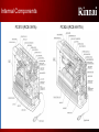
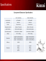
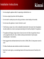
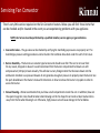
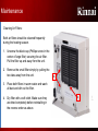
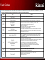
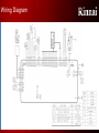
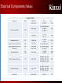
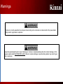
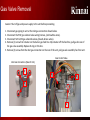
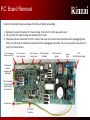
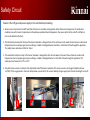
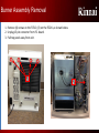
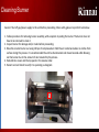
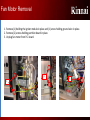
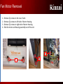
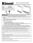
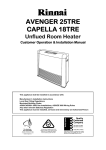
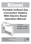
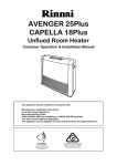
Rinnai
Fan Convector Heaters
Level III Training
1
Fan Convector Heaters
FC510 (RCE-391A)
FC824 (RCE-691TA)
Internal Components
FC510 (RCE-391A)
FC824 (RCE-691TA)
Specifications
Product specifications
Model
Gas Type
FC510N
(RCE-391AN)
Natural Gas
FC510P
(RCE-391AP)
Propane Gas
Input Rating Input Rating
Btu/hr. HIGH Btu/hr. LOW
10,000
10,000
5,500
5,600
Gas Inlet Pressure
Manifold Pressure
HI/LO Inches W.C.
(mm)
3.5 – 10.5 inches W.C
(89 – 267 mm W.C)
1.8 / 0.64 inches W.C.
(47 / 16.3 mm W.C.)
8.0 - 13.0 inches W.C.
(203 - 330 mm W.C.
3.2 / 1.12 inches W.C.
(82 / 28.6 mm W.C.)
Fan Motor
CFM HI/LO
Fuse
(Amps)
67.8 Low
97.8 High
5
67.8 Low
97.8 High
5
FC824N
(RCE-691TAN)
FC824P
(RCE-691TAP)
Natural Gas
Propane Gas
24,000
22,000
8,400
8,000
5.0 – 10.5 W.C
(127 - 267 mm W.C)
3.4 / 0.52 inches W.C.
(87 / 13 mm W.C.)
8.0 - 13.0 inches W.C.
(203 - 330 mm W.C.)
6.3 / 1.00 inches W.C
(161 / 25.5 mm W.C.)
109.5 Low
215.4 High
5
109.5 Low
215.4 High
5
Specifications
Component/Clearance Specifications
FC510 (RCE-391A)
FC824 ( RCE-691TA)
Gas Connection
1/2" Male NPT
1/2" Male NPT
Gas Control
Electronic
Electronic
Burners
Ceramic Burner
Ceramic Burner
Temperature Control
Electronic Thermostat
Electronic Thermostat
Ignition Sdystem
Electronic Spark Ignition
Electronic Spark Ignition
Electrical Connection
AC 120V, 60 Hz., 19 Watts
AC 120V, 60 Hz., 29 Watts
Weight
22.1 Lbs. (10kg)
26.5 Lbs. (12kg)
Dimensions
Height: 19.4 Inches (492 mm)
Width: 19.2 inches (487 mm)
Depth: 9.6 inches (244 mm)
Height: 19 Inches (482 mm)
Width: 24 inches (610 mm)
Depth: 9.4 inches (239 mm)
Efficiency
99.90%
99.90%
Clearances
Front 2"
Side 2"
Top 2"
Back 2"
Front 2"
Side 2"
Top 2"
Back 2"
Ledger Plate Explanation & Warranty
•
The letters “RCE” indicates this is a “Rinnai Convection Export” heater.
•
The numbers “510 & 824” indicate the model number of heater.
•
The letter “T” indicates duel timers on 824 model, no “T” indicates single timer on 510 model.
•
The letter “A” indicates this is an American version.
•
The “FC” indicates Fan Convertor Heater.
•
These units are not suitable for use in bathrooms or bedrooms. Vent-free heaters installed in
bathrooms and/or bedrooms must be wall mounted. This product can not be wall mount at the
present time.
•
Product warranty – 3 year parts, no labor.
Sequence of Operation
1. Convection fan starts, drawing air in through
the back of the cabinet and across the heat
exchanger / burner chamber and out into the
space. The PCB verifies fan rotation.
Thermocouple 1
Gas Valve
Solenoids
2. Once the fan is running at the proper speed,
spark ignition begins.
3. After spark begins, the gas valve solenoids
open allowing gas into the burner.
4. Ignition occurs and flame develops across the
burner.
Thermocouple 2
Combustion
Chamber
Spark
Electrode
POV
SV1
5. The PCB will verify flame with thermocouples
and turn off the sparker.
6. Warm air then begins to flow into the space.
P
C
B
7. PCB will determine gas input and fan speed
settings based on the room temperature
measurement from the room thermistor.
8. When thermostat set point is reached the gas
valve solenoids close. The combustion fan will
continue to run to cool down the unit.
9. When the room temperature drops below the
set point, the process will start again.
Room
Temperature
Thermistor
Convection
Fan Assembly
Modulating Technology
•
Variable speed technology – Modulating gas and air based on the heat loss at that moment
• With on/off single stage operation, gas usage
can be high due to alternating periods between
maximum flame and no flame at all
• The Fan Convector modulating technology has the
ability to replace only the heat escaping the
structure by continuously operating at heating levels
based on the demand at that moment
On / Off Single Stage Heating Appliance
Continuous-Run Modulating Technology
74°
74°
72°
72°
70°
70°
68°
68°
66°
Gas
Usage
Gas
Usage
Gas
Usage
• This results in different layers of temperatures
throughout the structure leading to a less than
comfortable living environment
8
66°
Continuous gas usage but at much lower levels
• This leads to lower gas usage and higher levels of comfort.
Note; if the “Auto Off” function is not selected the unit will
run continuously no matter what the room temperature is.
Installation Instructions
•
Do not install this appliance above 2,000ft.
•
Do not block the warm air discharge.
•
Do not allow anyone to sleep directly in front of the appliance.
•
Do not insert items into the louvers.
•
Do not place clothing or other flammable material on or near the appliance
•
Do not spray aerosols near the appliance while it is operating. Most aerosols contain butane gas
which is flammable.
•
Do not install this appliance in areas where spray painting or plating is taking place, or in places such
as hair salons where there may be large amounts of dust, chemical residue, or debris. Using the
appliance in such areas may result in strong odors or irritated eyes and sinuses.
•
Do not sit on the appliance.
Installation Instructions
•
Do not unplug the appliance while it is operating or while the fan is on.
•
Do not use a plug in type timer with this appliance.
•
Do not install in a windy area such as facing a window or a door leading to the outside.
•
Do not recess this appliance or mount it directly in a wall
•
If the flooring is carpet, tile, or other combustible material other than wood, then the appliance
must be installed on a metal or wood panel extending the full width and depth of the appliance.
•
This appliance discharges a large volume of warm air next to the floor. Any particles in the air
such as cigarette smoke, lint, dust, or debris could cause discoloration in nylon carpets
containing dyes or vinyl surfaces.
•
Rinnai suggests that a dedicated electrical circuit with a 120VAC, 60 hz, 10 amp power source be
used.
•
The flow of combustion and ventilation air shall not be obstructed.
•
Note that in some regions, an unvented gas heater will increase the amount of humidity in the
room.
Code Limitations
•
Check Federal, State and/or local codes in your state before using vent-free products. Some
areas of the country do not allow vent-free products.
•
International Fuel Gas Code Standard 620-6 under “Prohibited Use” states that; “One or more
unvented room heaters shall not be used as a sole source of comfort heating in any dwelling
unit”. Refer to the International Fuel Gas Code and International Fuel Gas Standard, Charter 6,
section 6-11, standard 620-2 for conformation of the above statement.
•
Code pertaining to bathroom installations. Refer to the 2000 International Fuel Gas Code,
section 303.3 “Prohibited locations”. under Exception 3. for prohibited use when installing
unvented heaters in a bathroom. It states, “A single wall mounted unvented room heater
equipped with an oxygen depletion safety shutoff system and installed in a bathroom
provided that the input rating does not exceed 6000 Btu per hour (1.76kW) and the bathroom
is not a confined space”.
•
Code pertaining to bedroom installations. Refer to the 2000 International Fuel Gas Code,
section 303.3 “Prohibited locations”. under Exception 4. for prohibited use when installing
unvented heaters in a bedroom. It states, “A single wall mounted unvented room heater
equipped with an oxygen depletion safety shutoff system and installed in a bedroom provided
that the input rating does not exceed 10,000 Btu per hour (2.93kW) and the bedroom is not a
confined space”.
•
The contractor installing this equipment has the responsibility to ensure the product being
installed meets all local and State building codes. Please check with your local code officials if
you have any questions related to vent-free products.
11
Servicing Fan Convector
There’s very little service required on the Fan Convector heaters. Below you will find three items that
can be checked and/or cleaned in the event you are experiencing problems with you appliance.
NOTE; ALL Service must be performed by a qualified installer, service agency or gas technician.
1. Gas control valve – The gas valve can be checked by verifying the manifold gas pressures are properly set. The
manifold gas pressure setting procedures can be found in the technical data sheet under the unit’s front cover.
2. Burner Assembly – The burners are ceramic type burners and should never fail if the unit is not over fired
for any reason, dropped or abused. I would recommend that the burner compartment be blown out with
compressed air (120 psi) at least annually. This will clear out any foreign matter that has been drawn into the
combustion chamber. Low pressure blowers do not generate enough air pressure to properly clean the burner. See
the parts breakdown in the Owner’s manual for directions on how to remove the burner’s top plate in order to
access the burner.
3. Annual Cleaning – Rinnai recommends that you blow out all compartments inside the unit. In addition, blow out
the squirrel cage fan. Care should be taken when blowing out the fan. Keep the air nozzle at least twelve inches
away from the fan when blowing it out. Otherwise, high pressure air will cause damage to the fan blades.
Maintenance
Cleaning Air Filters:
Both air filters should be cleaned frequently
during the heating season.
1. Unscrew the black cap (Phillips screw in the
center of large filter) securing the air filter.
Pull the filter up and away from the unit.
2. Remove the small filter simply by pulling the
two tabs away from the unit.
2
3. Place both filters in warm water and wash
all dust and dirt out the filter.
4. Dry filter with a soft cloth. Make sure they
are dried completely before reinstalling in
the reverse order as above.
1
Error Codes
&
Troubleshooting
14
Fault Codes
An error code will flash on the unit’s display when a fault occurs. Refer to the list of error codes below for details on your unit’s
fault code. All troubleshooting and repairs should be made by a licensed contractor.
ERROR
FAULT
00
Power Failure
03
Tilt Switch Activated
11
ODS #1
Missed Ignition
Burner Sensor
Pilot Sensor
12
ODS #1
ODS #2
Flame Failure
Burner ODS #1 & Pilot ODS #2
13
ODS #1
Overheat - Burner ODS #1
14
No Ignition
(No flame inside burner assembly)
Overheat Sensor
Thermo fuse
16
Room Overheat
REMEDY
- Press ON/Off button and allow unit to cycle on.
- Return unit to the upright position. Restart heater using the “ON” power button.
- Verify the gas supply is turned on to the appliance, gas meter, or tank
- Ensure gas type and inlet gas pressures are correct
- Bleed all air from gas lines
- Ensure gas line, meter, and / or regulator is sized properly
- Ensure appliance is properly grounded
- Verify ODS #1 and ODS #2 are producing the proper milli-voltage when unit fires.
- Inspect all wiring harnesses /connectors for loose, damage or broken connections .
- Replace defective ODS sensor
- ODS #1 left hand side of burner has sensed an over heat condition. Check filter
for blockage first. Then check fan for bad bearing, improper operation or hertz.
- Replace ODS #1 Sensor
- Verify air filter is in place and not clogged.
- Verify proper clearances around the appliance for air flow. Remove any obstructions.
- Check gas type of unit and ensure it matches gas type being used
- Verify low and high fire manifold gas pressures are properly set.
- Ensure DIP switches are set to the proper position on the PC board
- Check burner chamber for signs of heat stress, cracks and/or separations
- Check burner assembly for damage.
- Measure resistance of safety circuit
–
–
Verify unit was sized properly for space being heated.
Check for restrictions in air flow around unit.
– Check
18
15
Thermocouple #1
–
–
thermocouple wiring for damage, loose or broken wires.
Measure resistance of thermocouple
Replace thermocouple
Fault Codes
–
Check thermistor wiring for damage, loose or broken connections or wires.
Measure resistance of thermistor
Replace Sensor
–
Short circuit, replace thermistor
–
31
32
Room Temperature Thermistor
Room Temperature Thermistor
–
– Check
33
34
62
Overheat Thermistor
Overheat Thermistor
Combustion Fan Failure
–
thermistor wiring for damage, loose or broken connections or wires
Measure resistance of thermistor
Replace Sensor
–
Short Circuit, replace thermistor
–
Ensure fan will turn freely
Check wiring harness to motor for damaged and/or loose connections
Measure resistance of motor windings
Replace fan motor
–
–
–
–
–
70
ON/OFF Switch Faulty
–
–
–
71
Solenoids or Modulating Valve Circuit
–
–
–
72
ODS #1
ODS #2
73
Burner ODS #1 & Pilot ODS #2 initial
value abnormal
P.C Board abnormal
–
–
Check wiring harness from control panel to P.C board for loose or damaged wires or
connections.
Replace control panel
Check to ensure all gas solenoids or plugged into the solenoid valves.
Check to ensure they are plugged into the correct solenoid valve.
Check resistance value of all gas solenoid valves
Replace defective solenoid.
Replace P.C. board.
Verify low and high fire gas pressures were properly set.
Replace defective ODS Sensor
– Press
the ON/Off button twice to reset heater
Wiring Diagram
Electrical Components Values
Diagnostic Points
Components
Convection Fan Motor
Mark
CFM
Wire Colors
Value
Pin #
3&4
Blue - Brown
10 - 12 VDC
Blue - Yellow
2,000 - 5,000 Pulses/Min.
(33 - 84 Hz)
2K - 10 KΩ
1&3
Blue - Red
11 - 14 VDC
0.1K - 1 K
2&3
Modulation Gas Valve
POV
White - Red
1 - 14 VDC
65 - 90Ω
9 & 10
Oxygen Depletion Sensor #1 (TC1)
ODS1
Yellow - Blue
See next slide for details
5&7
Oxygen Depletion Sensor #2 (TC2)
ODS2
Yellow - Blue
See next slide for details
1&2
Sparker (IG)
IG
White - White
96 - 144 VAC
1&2
Gas Solenoid Valves
SV1
SV2
Blue - Brown
11 - 14 VDC
35 - 53Ω
1&2
4&5
Room Temperature Thermistor
TH
Black - Black
50°F (10°C) = 58K - 73KΩ
68°F (20°C) = 33K - 44KΩ
104°F (40°C) = 9K - 19KΩ
1&2
Over Heat Thermistor
OH.TH.
Black - Black
68°F (20°C) = 70K - 85KΩ
104°F (40°C) = 25K - 40KΩ
158° (70°C) = 8K - 15KΩ
3&4
Thermo-fuse
TF
White - White
Below 1Ω
6&8
Warnings
There are a number of (live) tests that are required when fault finding this product. Extreme care should be used
At all times to avoid contact with energized components inside the heater. Only trained and qualified service
Technicians should attempt to repair this product. Before checking for resistance readings, disconnect the power
Source to the unit and isolate the item from the circuit (unplug it).
Follow the steps below prior to servicing or replacing any components within the heater in order to protect yourself from harm:
• Turn off the electrical power supply by unplugging the power cord or by turning off the electricity at the circuit breaker. (The
product’s on/off switch does not control the electrical power).
• Turn off the gas at the manual gas valve, usually located behind the unit or within six foot of the appliance.
Warnings
Failure to correctly assemble the components according to the instructions contained within this presentation
May result in a gas leak or explosion
Inspect all gaskets/packings for signs of damage or corrosion. Gaskets/packings found to contain damage or that
Appear questionable MUST BE REPLACED. Failure to replace damage or questionable gaskets may result in gas
leak or explosion.
TC1 & TC2 Milli-volt Readings
Procedure for measuring TC1 & TC2 Thermocouple Outputs
1. Set voltage meter to read at least 35 milli-volts. Insert meter leads into the output test port holes on the
rear of the unit, see below for proper test ports for each thermocouple.
FC510 (RCE-391A) Thermocouple Output
TC1 (mV) Brown & White TC2 (mV) Black & White
Wires
Wires
Gas Type
High Fire
Low Fire
High Fire
Low Fire
Propane Gas
23 - 26
16 - 20
23 - 31
16 - 24
Natural Gas
26 - 29
17 - 21
18 - 26
15 - 23
FC824 (RCE-691TA) Thermocouple Output
TC1 (mV) Brown & White TC2 (mV) Black & White
Wires
Wires
High Fire
Low Fire
High Fire
Low Fire
23 - 26
16 - 20
23 - 31
16 - 24
26 - 29
17 - 21
18 - 26
15 - 23
2. Fire the unit up and check the milli-volt output on each thermocouple per readings listed above. Readings
below those listed above will cause the unit to code out. Verify inlet/manifold high/low fire gas pressures
if your readings are not within the specifications as listed above.
TC1 test ports - Top is the brown
& bottom right is white wire.
TC2 test ports - Bottom left is the
black & bottom right is white wire.
TC1
TC2
Gas Valve Removal
Caution: Shut off gas and power supply to the unit before proceeding.
1.
2.
3.
4.
Disconnect gas piping to unit at the inlet gas connection shown below.
Disconnect the POV gas solenoid valve wiring harness, (red & white wires).
Disconnect SV1 & SV2 gas solenoids valves, (blue & brown wires).
Remove (1) screw from retainer on the burner gas feed line. Slip retainer off the feed line, pull gas line out of
the gas valve assembly. Replace O-ring on this line.
5. Remove (3) screws from the inlet gas connection on the rear of the unit, pull gas vale assembly free from unit.
Gas Control Valve
Inlet Gas Connection (Rear of Unit)
1
3
2
5
4
P.C. Board Removal
Caution: Disconnect the power and gas from the unit before proceeding.
1. Remove (1) screw from plastic P.C. board casing, front of unit 1/3 the way up the unit.
2. Lift up on the P.C. board casing and pull board out of unit.
3. Disconnect all wire connectors from P.C. board. Take care not to stress the connections when unplugging them.
Press in on the latch to release the connector before unplugging connection. You can use a small screw driver to
push in on these latches.
10 Pin Connector
Safety Circuit/POV.
2 Pin Connector
Room Thermistor
15 Pin Connector
Control Panel
Push button
used to
program gas
pressures
6 Pin Connector
Thermocouple
output terminal
on rear of unit
Ground wire
SV1 & SV2
Connector
4 Pin Connector
Fan Motor
2 Pin Connector
Igniter
5 amp
fuse
2 Pin
120 Volt Power Supply
Safety Circuit
Caution: Shut off gas and power supply to the unit before proceeding.
1. Burner sensor mounted on the left hand side of the burner assembly is designed to detect the burner temperature. If combustion
conditions cause the burner temperature to drop below a predetermined temperature, the sensor will shut the unit off and flash an
error code related to the fault.
2. The thermal-fuse located on the top of the burner chamber is designed to shut the unit down in the event the unit senses an abnormal
temperature due to improper gas pressure settings, cracked or damaged burner chamber or restricted air flow through the appliance.
This safety device activates at 4200F or 216 0C.
3. The overheat thermistor on top of the burner chamber is designed to shut the unit down in the event the unit senses an abnormal
temperature due to improper gas pressure settings, cracked or damaged burner or restricted air flow through the appliance. This
safety device activates at 131 0F or 55 0C.
4. The pilot burner sensor is located on the right hand side of the burner assembly. This sensor serves as an Oxygen Depletion Sensor
or (ODS). If the oxygen level in the room drops below a preset limit, this sensor disables the gas supply to the heater shutting the unit off.
1
3
2
4
Igniter & Igniter Module Removal
Caution: Shut off gas and power supply to the unit before proceeding.
Igniter/electrode:
1. To remove the igniter unplug the black/green wires from the igniter. The green wire has a latch that has to be
pushed in, in order to release the connector. Remove cover plate with (1) screw.
2. Remove (2) screws from igniter bracket assembly, pull igniter/bracket assembly out of unit.
3. Replace igniter gasket before reassembling in reverse order.
Igniter Module:
4. To remove the igniter module unplug the wiring harness with two white wires from the PC board.
5. Pull large black wire out of module connection. Remove (1) screw and pull module from unit.
4
1
5
2
Igniter/electrode
Igniter module
Burner Assembly Removal
Next Seven Slides
Burner Assembly Removal
Caution: Shut off gas and power supply to the unit before proceeding.
1. Remove louver assembly by removing (3) screws as shown below.
2. Remove (2) screws from each side of the front cover, then pull cover away from unit.
FC510
FC824
1
1
2
2
Burner Assembly Removal
1. Remove (4) screws on the FC510, (3) on the FC824 ,as shown below.
2. Unplug 15 pin connector from P.C. board.
3. Pull top panel away from unit.
1
1
2
Burner Assembly Removal
Caution: Shut off gas and power supply to the unit before proceeding.
1. Disconnect the burner gas line from the gas control valve, (1) screw. Pull retainer clip off burner gas line. Pull gas
line loose from the gas control valve. Verify O-ring is intact and in good condition.
2. Unplug the fan motor wiring harness from the P.C. board.
3. Unplug (10) pin safety circuit wiring harness from the P.C. board.
4. Unplug the POV gas solenoid valve.
5. Unplug (2) pin connector at P.C. board for the igniter.
6. Disconnect both ground wires shown below.
1
4
POV solenoid valve
3
10 pin connector for safety circuit
2
4 pin connector for fan motor
5
2 pin connector for igniter
Burner gas line
6
Ground wires for PCB and power supply
Burner Assembly Removal
1. Remove the (4) screws on the rear of the unit.
2. Remove (1) screw from left side of burner housing down next to floor base.
3. Slide the complete burner and fan assembly out of the unit.
1
1
3
Burner Assembly Removal
1. Remove the burner sensor on the left hand side of the burner housing, (3) screws. Pull the
burner sensor retainer clip off the tab.
2. Remove the pilot assembly sensor and burner plate located on the right hand side of the burner
housing, (4) screws.
3. Remove the cover plate off the igniter (1) screw and the (2) screws in combustion box. Pull
igniter out of unit.
2
1
3
Burner Assembly Removal
1. Remove (2) screws from bracket and pull loose from unit.
2. Remove (4) screws for the combustion box cover and remove cover.
3. Remove (2) screws from burner assembly cover and remove cover.
1
2
3
Burner Assembly Removal
1.
2.
3.
4.
Remove (3) screws holding burner assembly to heater housing.
Slide burner assembly out of the burner chamber from right side of unit.
Complete burner assembly after removed from unit.
Install new burner assembly in reverse order.
2
3
1
Cleaning Burner Assembly
Cleaning Burner
Caution: Shut off gas/power supply to the unit before proceeding. Wear safety glasses to preform task below.
1. Follow procedure for removing burner assembly, with exception to pulling the burner. The burner does not
have to be removed to clean it.
2. Inspect burner for damage and/or cracks before proceeding.
3. Blow the ceramic burner out using 120 psi of compressed air. Hold the air nozzle back about six inches from
surface during this process. It is recommended the unit be disconnected and moved outside while blowing
out the burner due to the amount of dust created by this process.
4. Reinstall ALL covers and the top panel in the reverse order.
5. Restart unit and check to verify it is operating as designed.
1
Cleaning ODS Pilot Orifice
Cleaning ODS Pilot Orifice
Caution: Shut off gas/power supply to the unit before proceeding. Wear safety glasses to preform
task below.
1. Remove front cover on unit (4) screws.
2. Locate pilot and burner orifice on the right hand side of unit, center of burner housing.
3. Blow out the orifices shown in picture 1 with 120 psi of compressed air. Hold the air nozzle back
at least six inches from all components to prevent damage from the high pressure air.
4. Install front cover and verify unit operates as designed.
Pilot orifice
2
Burner orifice
Fan Motor/Squirrel Cage Blower Removal
Next Six Slides
Fan Motor Removal
Caution: Shut off gas and power supply to the unit before proceeding.
1. Remove louver assembly by removing (3) screws as shown below.
2. Remove (2) screws from each side of the front cover, then pull cover away from unit.
FC510
FC824
1
1
2
2
Fan Motor Removal
1. Remove (1) holding the igniter module in place and (1) screw holding ground wire in place.
2. Remove (2) screws holding partition board in place.
3. Unplug fan motor from P.C. board.
2
1
3
Fan Motor Removal
1.
2.
3.
4.
Remove (2) screws on the rear of unit.
Remove (2) screws on left side of burner housing.
Remove (2) screws on right side of burner housing.
Slide fan motor and housing assembly out of the unit.
3
1
2
Fan Motor Removal
1. Remove (4) screws holding fan motor to unit’s housing.
2. Loosen screw on fan motor shaft and pull fan motor loose from unit.
2
1
Squirrel Cage Blower Wheel Removal
1. Remove (2) screws on squirrel cage bearing housing assembly, left hand side of unit. Remove
bearing housing.
2. Loosen screw on fan motor shaft, right side of unit. Slide blower wheel out of unit from left side
of unit.
3. Reassemble in the reverse order.
2
1
The End
Fan Convection Heater
Service Training
44