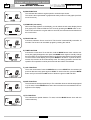
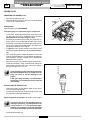
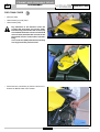
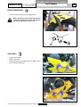
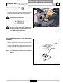
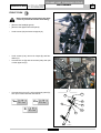
1
FRAME AND RUNNING GEAR
CNK 50 DRAKON
WORKSHOP MANUAL
FRAME AND RUNNING GEAR
TABLE OF CONTENTS
DRAKON 50 NKD
1
A
1 - INTRODUCTION
HANDLEBAR CONTROLS .....................................
20
Manual updates ................................................................
5
CLUTCH LEVER .....................................................
20
NOTES FOR EASY CONSULTATION .....................
5
FRONT BRAKE LEVER .........................................
20
Configuration of the pages ................................................
Modified pages .................................................................
Additional pages ...............................................................
Symbols ............................................................................
Abbreviations ....................................................................
Units of measurement .......................................................
5
5
5
6
6
6
2-STROKE ENGINE OIL .........................................
21
REAR CARRIER .....................................................
21
ADJUSTING
THE DRIVING POSITION .......................................
21
GENERAL WORK PROCEDURES .........................
7
Suggestions ......................................................................
Recommendations ............................................................
7
7
OPERATING SYMBOLS .........................................
9
2 - SPECIFICATIONS
TECHNICAL DATA .................................................
10
Dimensions .......................................................................
Weight ...............................................................................
Engine ...............................................................................
Type of oil ..........................................................................
Fuel ...................................................................................
Carburettor ........................................................................
Spark plug .........................................................................
Clutch ................................................................................
Transmission .....................................................................
Frame and running gear ...................................................
Tyres .................................................................................
Brakes ...............................................................................
Suspension .......................................................................
Electrical equipment .........................................................
Light bulbs .........................................................................
10
10
10
10
10
10
10
11
11
11
11
11
11
11
11
LUBRICANT TABLE ...............................................
12
DIMENSIONAL CHECK OF FRAME ......................
12
3 - DESCRIPTION
LEFT VIEW ..............................................................
13
RIGHT VIEW ...........................................................
13
CONTROLS / INSTRUMENTS ................................
14
4 - INSTRUMENT
AND CONTROL FUNCTION
MAIN SWITCH ........................................................
15
Keys ..................................................................................
Handlebar lock ..................................................................
15
15
INDICATOR LIGHTS ...............................................
15
DIGITAL INSTRUMENT PANEL .............................
16
Setting ...............................................................................
Miles or kilometres selection .............................................
Starting .............................................................................
Choosing functions ...........................................................
Speed ................................................................................
16
16
17
17
17
MAIN MENU FUNCTIONS ......................................
SUB-MENU FUNCTIONS .......................................
5 - PERIODIC MAINTENANCE
AND MINOR REPAIR
PERIODIC MAINTENANCE
AND LUBRICATION ...............................................
22
SPARK PLUG .........................................................
24
Removing the spark plug ..................................................
Inspection ..........................................................................
Installing the spark plug ....................................................
24
24
24
TRANSMISSION OIL ..............................................
25
Change .............................................................................
25
COOLING SYSTEM ................................................
26
AIR FILTER .............................................................
26
Disassembly ......................................................................
26
ADJUSTING THE CARBURETTOR ........................
27
ADJUSTING THE IDLING SPEED ..........................
27
ADJUSTING THE THROTTLE CABLE ...................
27
Adjustment ........................................................................
27
TYRES ....................................................................
28
Tire air pressure ................................................................
28
ADJUSTING THE CLUTCH LEVER
FREE PLAY .............................................................
28
ADJUSTING THE FRONT BRAKE
LEVER FREE PLAY ................................................
29
ADJUSTING THE REAR BRAKE
PEDAL POSITION ..................................................
29
CHECKING THE FRONT
AND REAR BRAKE PADS .....................................
29
CHECKING
THE BRAKE FLUID LEVEL ....................................
30
CHECKING
DRIVE CHAIN SLACK ............................................
30
ADJUSTING
DRIVE CHAIN SLACK ............................................
31
ADJUSTING THE BEAM ........................................
31
6 - USER INFORMATION
VEHICLE
IDENTIFICATION NUMBER ...................................
32
17
ENGINE
IDENTIFICATION NUMBER ...................................
32
19
ANTI-TAMPERING LABEL .....................................
32
3
03/06
FRAME AND RUNNING GEAR
A
1
TABLE OF CONTENTS
7 - DISASSEMBLY
DRAKON 50 NKD
FRONT DAMPER ....................................................
63
63
63
64
HEADLIGHT GUARD .............................................
33
ACCESSIBILITY .....................................................
34
Left ....................................................................................
Right ..................................................................................
Checking the oil level in the damper .................................
REPLACING THE HEADLIGHT BULBS .................
35
FRONT FORK .........................................................
65
Light bulbs used ................................................................
35
RADIATOR ..............................................................
66
HEADLIGHT ...........................................................
35
RADIATOR (assembly) ..........................................
67
DIGITAL INSTRUMENT PANEL .............................
36
MUFFLER ...............................................................
68
KEY SWITCH ..........................................................
37
OIL TANK ................................................................
70
HORN ......................................................................
37
Oil pump bleed ..................................................................
71
SEAT .......................................................................
38
ENGINE ...................................................................
72
ACCESSIBILITY .....................................................
38
CONTROLS ON THE HANDLEBAR .......................
74
BATTERY ................................................................
39
BRAKE CALIPERS OVERHAUL ............................
75
FUEL TANK COVER ...............................................
40
FUEL TANK .............................................................
41
Overhaul of rear caliper ....................................................
Overhaul of front caliper ....................................................
75
75
FUEL CAP ..............................................................
43
BRAKE MASTER CYLINDERS ..............................
77
LEFT AND RIGHT REAR FAIRING ........................
43
Front brake pump ..............................................................
Rear brake master cylinder ...............................................
77
78
ACCESSIBILITY .....................................................
44
BLEEDING THE BRAKE SYSTEM .........................
79
GRAB HANDLE ......................................................
44
FRONT MUDGUARD ..............................................
45
Front brake caliper ............................................................
Rear brake caliper .............................................................
79
80
SUB PANEL ............................................................
45
ACCESSIBILITY .....................................................
46
LEFT AND RIGHT SIDE PANEL .............................
46
INTAKE BOX GUARD .............................................
47
AIR FILTER .............................................................
47
SHOCK ABSORBER COVER ................................
48
REAR TAILLIGHT BULB ........................................
51
TURN INDICATOR BULB .......................................
52
REAR MUDGUARD ................................................
52
DRIVE CHAIN .........................................................
52
REAR SHOCK ABSORBER ...................................
53
REAR WHEEL .........................................................
53
SPROCKET ............................................................
54
REAR DISC .............................................................
54
REAR BRAKE CALIPER ........................................
55
Check the disc and pads of the rear brake for wear .........
55
FOOTREST ASSEMBLY - REAR BRAKE ..............
56
FOOTREST ASSEMBLY GEAR CHANGE PEDAL .........................................
56
FILTER BOX ...........................................................
57
SWING ARM ...........................................................
58
REAR FRAME ........................................................
59
SPEEDOMETER SENSOR .....................................
60
FRONT BRAKE CALIPER ......................................
61
Checking front brake wear ................................................
61
FRONT WHEEL ......................................................
62
FRONT BRAKE DISC .............................................
62
4
03/06
Introduction
FRAME AND RUNNING GEAR
1
INTRODUCTION
DRAKON 50 NKD
A
INTRODUCTION
• This Workshop Manual describes the main electrical/mechanical checks, the essential checks and the assembly of
components supplied disassembled in order to deliver a brand new vehicle (the sequence of operations is not
binding).
• It is essential to follow the instructions with great care. Work carried out carelessly or, worse still, work that has not
been accomplished, can cause injuries and damage or, in the less serious cases, complaints.
NOTE These manuals provide the necessary information and instructions for routine maintenance and servicing.
Some information has been given to us by the engine manufacturers. We therefore decline all responsibility for any error, omission or misrepresentation.
MALAGUTI reserves the right to make any changes and modifications hereto it deems necessary
without prior notice.
MANUAL UPDATES
• The updates will be sent by us (in a reasonable time). Every CD-Rom you receive will supersede the one already in
your possession.
• The table of contents will be duly updated in the event that new pages are inserted, which render the consultation
of the manual difficult.
• IMPORTANT! The Workshop Manuals are to be considered as essential tools to be properly kept up-to-date so as
to maintain their validity over time.
NOTES FOR EASY CONSULTATION
CONFIGURATION OF THE PAGES
A
X
Y
Y Chapter
X Section title
W Page N°
Z Date of issue
W
Z
MODIFIED PAGES
• Pages that have been modified will bear the same number as the same page of the previous edition, followed by a
letter M and, in the relative box, the new date of issue.
ADDITIONAL PAGES
• Any additional pages shall bear the last number of the section to which they belong, followed by the letter A and the
new edition date.
5
03/06
FRAME AND RUNNING GEAR
A
1
INTRODUCTION
DRAKON 50 NKD
SYMBOLS
• Symbols are provided for quick and easy reference (see the relevant heading), identifying situations requiring
utmost attention or providing practical suggestions or simple information.
• These symbols may appear next to a text (in which case they refer solely to the text itself), next to a figure (in
which case they refer to the topic illustrated in the figure and to the relative text), or at the top of the page (in which
case they refer to all the topics dealt with in the page).
NOTE The meaning of the symbols should be duly memorised as their scope is to avoid having to repeat
basic technical concepts or safety recommendations. They are therefore to be considered as “memory
tags”. In case of any doubt as to their meaning, consult the page in which they are fully described.
ABBREVIATIONS
F
Cs
P
Pr
S
Sc
T
V
Figure
Tightening torque
Page
Paragraph
Section
Diagram
Table
Screw
UNITS OF MEASUREMENT
All the dimensions in this Manual are shown in
mm.
NOTE The letter V in the illustrations refers to fixing or adjusting screws. The number following this letter
refers to the number of the same type of screw in the unit or component described and illustrated. A
letter without a number indicates quantity 1. In case of different screws being referred to in the illustration, the letter V is followed by a number and a lower case letter. Example: (V4a).
Unless otherwise specified, units and components are reassembled by proceeding in the reverse order of removal.
6
03/06
FRAME AND RUNNING GEAR
INTRODUCTION
DRAKON 50 NKD
1
A
GENERAL WORK PROCEDURES
• The advice, recommendations and warnings given hereafter are aimed at ensuring maximum work safety as well
as at considerably reducing the risk of accidents, personal injury, equipment damage and idle times. We therefore
recommend observing such advice, recommendations and warnings scrupulously.
SUGGESTIONS
• Only use top quality tools and equipment.
• Only use equipment conforming to EU Directives for lifting the vehicle.
• During all operations keep tools close at hand, ideally in accordance with a predetermined sequence of use, and
anyway never leave tools on the vehicle or in concealed or hard to reach positions.
• Always keep the work area clean and tidy.
• When tightening screws or nuts, start with the larger diameter or inner fasteners, and tighten them in a “crosswise
pattern” in successive “torquing steps”.
• Preferably use open-end wrenches and tighten by exerting “pulling force” rather than “pushing force”.
• Adjustable wrenches should only be used in case of
emergency, i.e. when a properly sized wrench is not
available. During the torquing stage the movable jaw
tends to open thus risking damaging the screw head or
achieving unreliable tightening torque values. In any
case, when using an adjustable wrench, take care to
proceed as shown in the figure.
• Except in the case of occasional services, prepare a
work sheet for the customer, on which to take a note of
all the work performed and write memos relating to any
future checks that may be required.
RECOMMENDATIONS
• Before carrying out any work on the vehicle wait for all
the parts to cool down completely.
• For operations requiring two mechanics, make sure that
the various steps to be performed by each of them are
clearly defined and coordinated beforehand.
• Make sure that each component has been properly fitted before proceeding with the next one.
• Lubricate all parts (where applicable) before reinstalling them.
• Gaskets, oil seals, snap rings and cotters must be renewed at every refitting.
• The torque settings specified in the manuals refer to
the “final torque”, which must be reached progressively
by steps.
• Loosen and tighten aluminium alloy parts (covers) only
after the engine has cooled down fully.
• Only use screwdrivers of suitable sizes in relation to
the screws to be loosened or tightened.
• Work in a comfortable position and ensure that the vehicle is stable.
• Never use a screwdriver as a lever or chisel.
• Never use pliers to loosen or tighten screws or nuts because, in addition to not providing a sufficient clamping force,
they may also damage the screw head or nut hex.
• Never tap wrenches with a hammer (or other similar tools) to loosen or tighten screws and nuts.
• Never attempt to increase leverage by attaching tubes, etc. to wrenches.
7
03/06
FRAME AND RUNNING GEAR
A
1
INTRODUCTION
DRAKON 50 NKD
Never use open flames for any reason.
Never leave open containers or containers not suitable for holding fuel in passageways, close to
heat sources. etc.
Never use petrol to clean the vehicle or the workshop floor. Always use low flash point solvents to
clean the vehicle components.
Never suck from or blow into the fuel pipe.
When welding, make sure that there are no flammable liquids in the vicinity. Always remove the fuel
tank, even if completely empty, and disconnect the negative cable (-) from the battery.
Never leave the engine running in closed or poorly ventilated areas.
Before any servicing, make sure that the vehicle is perfectly stable.
The front wheel should preferably be anchored to fixture (A), which is integral with the lift platform.
A
05189300
8
03/06
FRAME AND RUNNING GEAR
INTRODUCTION
DRAKON 50 NKD
1
A
OPERATING SYMBOLS
IMPORTANT!
CAUTION! - Descriptions concerning operations that are potentially hazardous for the maintenance
mechanic or repairman, other workshop personnel or extraneous persons, for the environment, for the
vehicle, and for the tools and equipment.
DISCONNECT POWER - Before performing the work described, disconnect the battery negative cable.
RISK OF FIRE - Indicates operations that may constitute a fire hazard.
EXPLOSION HAZARD - Indicates operations that may constitute a risk of explosion.
TOXIC FUMES - Indicates the risk of intoxication or inflammation of the respiratory tract.
NO! - Operations to be absolutely avoided.
SYMMETRICAL OPERATIONS - Operations to repeat on both sides of the unit or component in question.
ENGINE WORKSHOP MANUAL - Information that can be found in the engine workshop manual.
FITTING AND ASSEMBLY OPERATIONS
REMOVAL AND DISASSEMBLY OPERATIONS
9
03/06
SPECIFI-
A
FRAME AND RUNNING GEAR
SPECIFICATIONS
2
DRAKON 50 NKD
TECHNICAL DATA
D
05189050
A
B
C
DIMENSIONS
TYPE OF OIL
Length (B)
1970
Width (C)
755
Height (D)
Wheel base (A)
1050
1325 ± 20
Engined oil
Tank capacity
Reserve
Transmission oil
Engine capacity
Oil for 2-stroke engines
(JASO FC or ISO-LEGD)
10 l.
0.3 l.
SAE 10W40
0.82 l.
WEIGHT
During operation, kg
118
Maximum load, kg
160
(Total weight of rider, passenger, cargo and accessories)
FUEL
Type
Tank capacity
Reserve
ENGINE
Type
Cylinder arrangement
Displacement
2-stroke, liquid-cooled
Forward-inclined single-cylinder
49 cm3
Bore x stroke
40.3 x 39 mm
Compression ratio
Starting system
Lubrication system
12:1 ± 0.5
Electric
Separate
Regular unleaded petrol
95 RON
9.5 l.
1.8 l.
CARBURETTOR
Type
PHBN16 / DELL’ORTO
SPARK PLUG
Type
Gap in mm
10
03/06
NGK BR9ES
0.6 ÷ 0.7
FRAME AND RUNNING GEAR
SPECIFICATIONS
DRAKON 50 NKD
CLUTCH
Type
2
A
BRAKES
Mechanical
Disk brake with hydraulic transmission
Front
Right hand operation
Rear
Right foot pedal control
TRANSMISSION
Primary reduction system
Helical gear
Primary reduction ratio
71 / 20 (3.55)
SUSPENSION
Front
Max. stroke
Rear
Secondary reduction system Mechanical chain drive
Hydraulic fork, stems Ø 36 mm
88 ± 2 mm
Swing arm with shock
absorber
28 ± 2 mm
Secondary reduction ratio
48 / 11 (4.36)
Transmission type
6-speed
Type
Left foot operation
ELECTRICAL EQUIPMENT
Gear ratio
1
2
3
4
5
6
Ignition system
Charging system,
rated power
Battery
FLYWHEEL MAGNET, 95W
Maintenance-free
Battery capacity
12V, 5 Ah
12/36
16/33
19/29
22/27
24/25
25/24
Max. stroke
1:3
1:2.06
1:1.52
1:1.23
1:1.04
1:0.96
C. D. I.
LIGHT BULBS
FRAME AND RUNNING GEAR
Frame
Angle
Welded steel tubular structure
28°
Headlight
Tail-light
Indicators front/rear
Indicator lights
Parking light
TYRES
Type
Front
Rear
Low beam indicator light
Tubeless
100/80-17 52S
130/70-17 62S
Number plate light
11
03/06
12V 35/35W
13.5V 0.36 W / 2.7 W
12V 10W x 4
LED
12V 3W
(Switzerland version only)
12V 1,2W
(Switzerland version only)
12V 5W
(Switzerland version only)
FRAME AND RUNNING GEAR
A
2
SPECIFICATIONS
DRAKON 50 NKD
LUBRICANT TABLE
LUBRICANTS
TYPE OF LUBRICANT
ENGINE OIL
Q8 CLASS 10W 40
MIX OIL
Q8 CITY BIKE ULTRA
Q8 DAILY SUPER
LUBRICANT FOR CHAINS
Q8 CHAIN LUBE
OIL FOR AIR FILTERS
Q8 AIR FILTER OIL
RADIATOR FLUID
Q8 TOP FLUID
BRAKE FLUID
Q8 BRAKE FLUID DOT 4
05189057
DIMENSIONAL CHECK OF FRAME
If the scooter has been involved in an accident and you suspect even slight distortion of the frame it is essential to
perform the dimensional checking procedure before any further “repair or set-up” work.
Control dimension (A) must be 1001 mm with a tolerance of ± 2 mm.
Control dimension (B) must be 432,5 mm with a tolerance of ± 2 mm.
Do not attempt to bend the frame to restore the original “A” measurement.
12
03/06
DESCRIP-
FRAME AND RUNNING GEAR
3
DESCRIPTION
DRAKON 50 NKD
A
LEFT VIEW
1)
2)
3)
4)
5)
6)
Headlight
Oil tank
Shift pedal
Air filter
Battery
Passenger holder
6
1
5
2
4
3
05189002
RIGHT VIEW
6)
7)
8)
9)
10)
11)
12)
13)
14)
Passenger holder
Tail light
Number plate light +
number plate holder
(SWITZERLAND only)
Passenger footrests
Rear brake pedal
Radiator
Fuel tank cap
Fuse
Owner’s tool bag
14
13
12
6
7
11
8
10
9
05189003
13
03/06
FRAME AND RUNNING GEAR
A
DESCRIPTION
3
DRAKON 50 NKD
CONTROLS / INSTRUMENTS
15)
16)
17)
18)
19)
20)
21)
22)
23)
24)
25)
Manual starter lever
MODE switch
Clutch lever
Rear-view mirror
Left handlebar switches
Starter button
Throttle grip
Front brake lever
Front brake pump
Multifunction digital instrument panel
Main switch
25
24
15
17
18
22 21
23
16
19
20
05189004
14
03/06
INSTRU-
FRAME AND RUNNING GEAR
INSTRUMENT
AND CONTROL FUNCTION
DRAKON 50 NKD
4
A
MAIN SWITCH
The main switch controls the ignition circuit and steering
lock.
: all electrical contacts are disconnected.
: the contacts are activated; the engine can start and
the lights come on.
the steering lock is on.
KEYS
The scooter is provided with two keys
making it possible to:
•
•
•
05189005
Providing the ignition contact.
Turning the lights on.
Locking the steering system.
HANDLEBAR LOCK
Locking: turn the handlebar all the way to the right or left,
push the key in and turn it counter-clockwise.
Disengaging: turn the key clockwise.
INDICATOR LIGHTS
1) Turn signal indicator light
This light flashes when the turn indicator is pushed to
the left or right.
2) Low beam indicator light
This indicator comes on when the low beam headlight
is operated.
3) Fuel level warning light
This light comes on when the fuel level is low. Fill the
fuel tank.
4) Coolant temperature warning light
This light comes on when the temperature of the coolant is too high.
5
1
6
2
4
3
When this light comes on, stop the engine at
once and follow the instructions on page 24.
05189007
5) Neutral indicator light “N”
This light comes on when the transmission is in neutral
position.
15
03/06
FRAME AND RUNNING GEAR
A
4
INSTRUMENT
AND CONTROL FUNCTION
DRAKON 50 NKD
DIGITAL INSTRUMENT PANEL
This new digital instrument board offers several additional functions- compared to traditional ones - through which
driver may optimally manage his/her vehicle. The panel is equipped with a warning light signalling shortage of coolant
or improper connection with the radiator’s thermostat. This light comes on automatically. To select the functions shown
on the display, press the MODE button located at the front of the left hand control (see page 18).
Available functions are:
0-40 (acceleration from 0 to 40 km/h),
TIME (clock),
LAP (chronometer),
AVE (average speed),
TD (partial distance),
TOD (total distance),
BAR GRAPH with three functions: battery charge level, coolant temperature, number of engine revolutions.
For the English version, the display will be in miles, not km. The digital instrument board only works
if the battery is connected. If the battery is flat, replace it immediately. When the battery is replaced or
the fuse is removed, power is disconnected; any settings memorised on the instrument panel, except
the total distance travelled, will be reset.
Replace the flat battery with a new one; if the problem remains, call an Authorised MALAGUTI Service Centre.
Do not use your vehicle when no function appears on the display or when functions appear partially,
since the instrument board is not in the condition to provide sufficient information about your vehicle.
SETTING
Power up the instrument board by connecting the battery to the vehicle’s cables. Put the key in the ignition switch and
turn it to. The names of stored flywheels appear successively on the display: before selecting your type, check the type
of flywheel installedon your vehicle on the anti-tampering label under the seat (seepage 33). When the code of your
model appears on the display, press the MODE button, to make your selection. If you choose the wrong model, you will
be shown improper information (speed, km, etc.). If you choose the wrong model, turn the panel off, wait for about two
minutes and repeat the above operations in the correct manner.
These operations must be repeated every time the battery is disconnected.
MILES OR KILOMETRES SELECTION
If you are driving in countries with different measurement systems, you can change the unit of measurement of speed
(instant and average) and distance from kilometres to miles and vice versa. To make your selection, first of all the
vehicle must be stationary. Now hold the MODE button down for 5” after selecting the TOD function. When „Mph“ and
„Km/h“ appear, give the MODE button short presses until the unit of measurement starts flashing. Hold the MODE
button down to save your selection. The instrument board will return to its normal display mode. Any stored information
(with the exception of TOD) will be reset.
Using a unit of measurement that differs from the one used in the country where you are driving may
lead to improper calculations, especially concerning the vehicle’s speed. Consequences include exposure of the driver and others to dangers, as well as fines.
16
03/06
FRAME AND RUNNING GEAR
INSTRUMENT
AND CONTROL FUNCTION
DRAKON 50 NKD
4
A
STARTING
Put the key into the ignition switch and turn it to
. A check for all operations will automatically appear for 3 seconds,
after which the last function used before turning off the vehicle will appear.
The check is automatically performed every time the key is turned to. If the check is not displayed,
contact an authorised MALAGUTI Service Centre.
CHOOSING FUNCTIONS
Functions are divided into menus and sub-menus (bar
graph), which make the display easier to understand.
To select a function, press the MODE button, as shown in
the diagram.
The diagram shows you for how long the MODE button
should be held down (near the arrows).
To help you identify the functions and acquire information
about their characteristics, a description is provided here
below, indicating the functions in the order in which they
appear on the display
Sub-menu functions
(Bar graph)
Speed
Main menu functions
05189008
Menu functions can be seen from every submenu.
SPEED
This numeric value is displayed in km/h. This is the only
function that is shown on the display at all times.
MAIN MENU FUNCTIONS
1"
A
1"
00001
B
1"
00
C
(rev counter)
TOD (total)
STAND-BY
5"
TD (partial)
2"
Reset
1"
E
Acceleration
18-45 TIME
TIME (time)
4"
Submenu selection
(Bar graph)
Km/h
000.0 TD
0 40
1"
Selection Mp/h
H
D
-----
Time adjustment
RPM / Vbatt / TempH2O
1"
G
AVE
0.0
1"
1"
Stop
Reset/Start
1"
F
LA P
00'00"
1"
LAP (chronometer)
AVE (average)
2"
05189009
Reset
A) TOD FUNCTION
This indicates the total distance travelled; this value is never reset and remains even
after the vehicle is turned off (the total distance travelled will be stored for 10 years
running from the last time the vehicle was used).
05189010
17
03/06
FRAME AND RUNNING GEAR
A
4
INSTRUMENT
AND CONTROL FUNCTION
DRAKON 50 NKD
B) RPM FUNCTION
This indicates the vehicle’s engine speed in revolutions per minute.
This value is also represented in graphical format by means of a bar graph (see Submenu Functions).
05189011
C) STAND-BY (sub-menu)
When this image appears on the display, you can switch the sub-menu display format
(bar graph) from V-batt to RPM and vice versa by pressing the MODE within 3 seconds. If this command is not given within 3 seconds, the instrument board switches to
the 0-40 function.
05189012
D) FUNCTION 0-40
It shows acceleration from 0 to 40 km/h. This function is automatically reset after 15
seconds. The function can be called up again by starting the vehicle.
05189013
05189014
E) TIME FUNCTION
It shows the current time. To set the time, hold the MODE button down until the submenu (bar graph) disappears, then press the MODE button again to actually change
the time setting. The increase will be slow for the first ten units and then become faster.
To return to the normal display, do not press MODE for at least 3”. If power is disconnected, this function will be automatically reset. The setting operation must be thus
repeated. This operation must be performed with the vehicle at a standstill
F) LAP FUNCTION
This is the chronometer. Press the MODE button once to START the chronometer (all
previous data are reset); press again to STOP. To use this function, press the MODE
button until you relocate the LAP function. Values are given in MIN and SEC.
05189015
G) AVE FUNCTION
This indicates the average speed in mph. The calculation does not include stops (speed
= 0). To reset, hold the MODE button down when the vehicle is at a standstill until a ‘0’
appears on the display.
05189016
H) TD FUNCTION
This indicates the partial distance. To reset, hold the MODE button down with the
vehicle stationary.
05189017
18
03/06
FRAME AND RUNNING GEAR
INSTRUMENT
AND CONTROL FUNCTION
DRAKON 50 NKD
4
A
SUB-MENU FUNCTIONS
FUNCTIONS OF THE BAR GRAPH
To select one of the bar graph functions, open the main STAND-BY menu. When “- - - -”
appears on the display, press the MODE button within 3”. The bar graph will switch from
engine speed (RPM) to battery charge level (V-batt) and finally to coolant temperature
(Temp H2O). The function is stored after 3 seconds.
05189012
05189018
BATTERY CHARGE LEVEL
This check should be made with the engine off; if battery power drops to MIN., the symbol
will flicker, irrespective of the function displayed.
When the battery charge level drops to its minimum threshold, the battery level function is
automatically activated, irrespective of the function selected, and the last dash of the bar
graph will flash. If you change function, the battery logo will remain displayed until the
correct power supply is resumed.
When the warning light comes on charge the battery as soon as possible.
RPM - ENGINE SPEED
This function shows engine speed in graphic format. The numeric value can be displayed
with the RPM function of the Main Menu.
05189019
05189020
COOLANT TEMPERATURE INDICATOR
This displays the operating temperature of the coolant circuit.
When the temperature of the cooling circuitries s above the permissible threshold, the red
indicator light on the instrument board will come on; stop the vehicle and follow the instructions provided on page 26.
Should the temperature probe not be connected, the red warning light on the right hand
side of the instrument board will flash.
19
03/06
FRAME AND RUNNING GEAR
A
4
INSTRUMENT
AND CONTROL FUNCTION
DRAKON 50 NKD
HANDLEBAR CONTROLS
1) Horn switch
Press this switch to sound the horn.
B
A
2) Turn indicator switch
To signal a right-hand turn, push the switch rightwards;
push leftwards for a left-hand turn. When released, the
switch returns to centre. To disable the turn signals,
press the switch.
3) Starter (choke) lever
Using this lever helps cold starting the scooter; remember to reposition the starter in the closed position, B,
after warming up the engine (B - closed; A - open).
3
4
5
1
2
05189021
4) MODE button
Press this button to select functions of the digital instrument board.
6
5) Low beam/high beam light switch
This switch operates the low beam/high beam lights.
05189022
6) START button
This button starts the engine. This button is active only
when the main switch is ON and the clutch lever is
operated.
CLUTCH LEVER
The clutch lever is located on the left-hand side of the
handlebar. It engages or disengages the clutch. Pull the
clutch lever towards the handlebar to disengage the clutch
and release it to engage it. For smooth clutch operation,
the lever must be pulled rapidly and released slowly.
05189023
FRONT BRAKE LEVER
The front brake lever is on the right-hand side of the handlebar. To apply the front brake, pull the lever towards the
handlebar.
05189024
20
03/06
FRAME AND RUNNING GEAR
INSTRUMENT
AND CONTROL FUNCTION
DRAKON 50 NKD
A
4
2-STROKE ENGINE OIL
Make sure that there is sufficient oil in the 2stroke engine oil tank.
Never use the vehicle without oil.
To fill the tank with oil, remove the cap (T) and pour the oil
carefully in.
T
There is an electrical contact inside the tank that turns the
red reserve light of the instrument board on when the tank
is running out of lubricant.
When the reserve light comes on, fill the tank at the first
opportunity.
OIL TANK
Lt
TOTAL TANK CAPACITY
Reserve
1.3
0.3
05189025
Recommended oil
JASO FC or ISO-LEGA2-STROKE
ENGINE OIL
REAR CARRIER
Do not exceed the load limit: 2 kg.
ADJUSTING THE DRIVING POSITION
By moving the bottom fastening element of shock absorber (M) (double hole in the bottom fixing bracket), you can
adjust the height of the vehicle’s seat.
M
This operation must be performed by an Authorised MALAGUTI Service Centre.
05189026
21
03/06
MANUTENZIOPERIODIC
A
FRAME AND RUNNING GEAR
5
PERIODIC MAINTENANCE
AND MINOR REPAIR
DRAKON 50 NKD
PERIODIC MAINTENANCE AND LUBRICATION
The annual checks must be performed every year, except if a kilometre-based maintenance is performed instead.
From 30,000 km (18641. 14 mi), repeat the maintenance intervals starting from 6,000 km (3728. 23 mi).
Items marked with an asterisk should be performed by a MALAGUTI Dealer as they require special tools,
data and technical skills.
Servicing the scooter should be done every 6000 Km, except for the first service after only 1000 Km.
POSITION
N.
ODOMETER READING
(X 1000 KM) (621, 37 MI)
CHECKS OR MAINTENANCE JOB
1
1
*
Fuel line
2
*
Spark plug
3
*
Air filter element
4
*
Battery
5
*
Clutch
6
*
Front brake
6
12
18
24
• Check fuel hoses for cracks or damages.
X
X
X
X
X
• Replace
X
X
X
X
X
•
•
•
•
•
•
X
Clean
Replace
Check electrolyte level and specific gravity.
Make sure that the breather hose is properly routed.
Check operation.
Adjust.
• Check operation, fluid level and vehicle for fluid leakage.
*
Rear brake
X
X
X
X
X
X
X
X
X
X
X
X
X
X
X
X
X
• Check operation, fluid level and vehicle for fluid leakage.
X
X
X
X
X
X
X
X
X
*
Brake hoses
9
*
Wheels
• Check for run out and damage and check tightness
of spokes.
• Tighten spokes if necessary.
X
X
X
X
10
*
Tyres
•
•
•
•
X
X
X
X
11
*
Wheel bearings
• Check for looseness and damage.
X
X
X
X
12
*
Swing arm
• Check operation and for excessive play.
X
X
X
X
X
X
X
X
X
X
Every 4 years
Check tread depth and for damage.
Replace if necessary.
Check air pressure.
Correct if necessary.
• Lubricate with lithium-soap based grease.
Drive chain
X
Check every 2000 km if worn to the limit (1242, 74 mi)
• Replace brake pads.
• Check for cracks or damage
• Replace
8
13
X
Check every 2000 km if worn to the limit (1242, 74 mi)
• Replace brake pads.
7
ANNUAL
CHECK
X
• Check chain slack.
• Make sure the rear wheel is properly aligned.
• Clean and lubricate.
• Check bearing play and steering for roughness.
• Lubricate with lithium-soap based grease.
• Make sure that all nuts, bolts and screws are properly tightened.
• Check operation.
• Lubricate.
• Check operation and for oil leakage.
14
*
Steering bearings
15
*
Chassis fasteners
16
*
Side stand
17
*
Fork
18
*
Shock absorber
assembly
• Check operation and shock absorber for oil leakage.
*
Rear suspension
relay arm and
connecting arm
pivoting points
• Check operation.
19
• Lubricate with lithium-soap based grease.
22
03/06
X
Every 500 km and after washing the vehicle
or riding in the rain (318, 68 mi)
X
X
X
X
X
Every 24, 000 km (14912, 91 mi)
X
X
X
X
X
X
X
X
X
X
X
X
X
X
X
X
X
X
X
X
X
X
X
X
FRAME AND RUNNING GEAR
PERIODIC MAINTENANCE
AND MINOR REPAIR
DRAKON 50 NKD
N.
POSITION
20
*
Carburettor
21
*
Mix oil pump
22
*
Transmission oil
23
*
Cooling system
24
*
25
*
26
*
Front and rear brake
switches
Moving parts
and cables
Lights, signals
and switches
ODOMETER READING
(X 1000 KM) (621, 37 MI)
CHECKS OR MAINTENANCE JOB
•
•
•
•
•
•
Check choke operation.
Adjust engine idling speed.
Check operation.
Purge air if necessary.
Check oil level.
Change.
A
5
ANNUAL
CHECK
1
6
12
18
24
X
X
X
X
X
X
X
X
X
X
X
• Check coolant level and vehicle for coolant leakage
X
Every 3000 km (1864. 11 mi)
X
X
X
X
X
X
X
X
X
X
• Change.
Every 3 years
X
• Check operation.
• Lubricate.
• Check operation.
• Adjust the headlight.
X
X
X
X
X
X
X
X
X
X
X
X
X
X
X
X
The air filter needs more frequent service if you are riding in unusually wet or dusty areas.
Hydraulic brake service:
- Regularly check and, if necessary, correct the brake fluid level.
- Replace the brake hoses every four years and if cracked or damaged.
The maintenance schedule is based on average riding conditions. Machines subject to severe use or
ridden in unusually wet or dusty conditions or off the road require more frequent servicing.
23
03/06
MANUTENZIO-
FRAME AND RUNNING GEAR
A
5
PERIODIC MAINTENANCE
AND MINOR REPAIR
DRAKON 50 NKD
SPARK PLUG
REMOVING THE SPARK PLUG
• Remove the spark plug cap.
• Unscrew the spark plug (C) with the wrench provided
in the tool kit, and remove it.
C
INSPECTION
Specified spark plug: NGK BR9ES
The spark plug is an important engine component.
•
•
•
•
To service it, simply remove the plug cap and unscrew
the plug with the wrench supplied for this purposes
(take particular care if the engine is hot).
Examine the condition of the spark plug when the engine is warm, since the deposits and the colour of the
insulator provide useful information about the thermal
rating of the plug, about carburation, lubrication and
the general condition of the engine
A light tan colour of the insulator around the centre
electrode indicates that engine is correctly functioning.
If the spark plug shows a distinctly different colour, the
engine could be defective. Do not attempt to diagnose
such problems yourself. Instead have a MALAGUTI
Dealer check the vehicle.
Remove the spark plug and thoroughly clean its electrodes and insulator, using a metal brush. Adjust the
gap between the electrodes with a thickness gauge:
the gap should be 0.6 - 0.7 mm.
05189027
0,6 - 0,7 mm
•
Using spark plugs with heat rating other than
the recommended value (as marked on the
plug) can result in serious damage to the
engine.
If the spark plug insulator is cracked and/or
electrodes are corroded it must be replaced
immediately.
INSTALLING THE SPARK PLUG
• Clean the surface of the gasket. Wipe off any grime
from the spark plug threads.
• Install the spark plug with the spark plug wrench, and
then tighten it to the specified torque.
05053573
Spark plug tightening torque: 20/25 Nm (2.0/2.5 Kgm)
If a torque wrench is not available when installing a spark plug, a good estimate of the
correct torque is ¼ - ½ turn past finger tight.
However, the spark plug should be tightened
to the specified torque as soon as possible.
•
Install the spark plug cap.
24
03/06
FRAME AND RUNNING GEAR
PERIODIC MAINTENANCE
AND MINOR REPAIR
DRAKON 50 NKD
A
5
TRANSMISSION OIL
CHANGE
•
•
•
•
•
•
•
•
•
•
Park the vehicle on flat ground.
Start the engine and warm it up for several minutes.
Stop the engine.
Remove crankcase (C) by loosening the four screws, (V).
Place an oil pan under the engine and remove the filler
cap, (R).
Remove the drain screw, (S), and screw (F) to drain
the oil.
Reinstall the drain screw and then tighten it to the specified torque.
Drain screw tightening torque: 17/18 Nm (1.7/1.8 Kgm).
Fill the engine with oil until this is dripping from the
level control hole, (F). Fit the screw back into hole (F),
install the oil filler cap, (R), and tighten it.
The use of SAE 10W 40 oil is recommended.
Refit crankcase (C) and secure in place by tightening
the four screws, (V).
R
F
S
05189029
C
Do not mix any chemical additives with the
oil. Transmission oil also lubricates the clutch
and chemical additives may cause slippage.
Dispose of oil in accordance to the laws in
force: DO NOT DISPOSE OF WASTE OIL IN
THE ENVIRONMENT.
During this operation, avoid any contact with
the cylinder: DANGER OF SCORCHING.
Start the engine and let it warm up for a few minutes. While
it is warming up, check for oil leakage. If oil is leaking,
immediately turn off the engine and locate the cause.
Check oil level every 3000 km. (1864. 11 mi)
Change oil every 6000 km. (3728. 23 mi)
Engine crankcase capacity: 0. 82 L.
25
03/06
V
MANUTENZIO-
FRAME AND RUNNING GEAR
A
5
PERIODIC MAINTENANCE
AND MINOR REPAIR
DRAKON 50 NKD
COOLING SYSTEM
•
Remove cap (T).
•
The coolant level must be checked on a cold engine
since the level varies with engine temperature. The
coolant should be between the maximum “Mx” (top end
of the radiator) and minimum level “Mn” (start of battery cells) marks.
•
If the level is low, add coolant or distilled water until the
specified level is reached.
•
Refit the cap.
T
05189030
Salt or hard water is dangerous for the engine. If you do not have any coolant you can
use distilled water or fresh water. In winter it
is necessary to correct the proportion of
coolant and water in order to avoid freezing
or possible damage.
Mx
Mn
05189031
AIR FILTER
V
DISASSEMBLY
•
•
•
Remove the seat, (S), by slackening screw (V).
Remove the general protection fuse.
Remove battery (B) by removing the elastic band and
disconnecting the terminals.
• Remove partition (P) to access screw (R).
• Remove filter (F) by slackening the two fixing screws,
(R).
The air filter element must be cleaned at the intervals specified. Clean the air filter more frequently if you are riding in
unusually wet or dusty areas.
S
B
R
F
05189031
Make sure the air filter element is properly
seated in the air filter case.
The engine should never be operated without the air filter element, otherwise the piston and/or cylinder may become excessively worn.
P
05189031
R
26
03/06
FRAME AND RUNNING GEAR
PERIODIC MAINTENANCE
AND MINOR REPAIR
DRAKON 50 NKD
5
ADJUSTING THE CARBURETTOR
The carburettor is an important part of the engine and requires very accurate adjustments.
Therefore, most carburettor adjustments should be left to
an Authorised MALAGUTI Service Centre, who has the
necessary professional knowledge and experience.
The carburettor has been set and extensively tested
at the MALAGUTI factory. Changing these settings may
result in poor performance or damage to the engine.
ADJUSTING THE IDLING SPEED
•
•
Start the engine and warm it up for several minutes at
about 1000-2000 rpm, while occasionally revving it to
4000 to 5000 RPM. The engine is warm when it quickly
responds to the throttle.
To adjust the engine idling speed, turn the throttle stop
screw, (G). Turn the screw clockwise to increase idling
speed or counter-clockwise to decrease it.
G
Standard engine idling speed: 1800- 2000 rpm.
05189034
ADJUSTING THE THROTTLE CABLE
The engine idling speed must be correctly
adjusted before checking and adjusting the
throttle cable free play.
3-5 mm
Adjust the throttle cable by turning the adjusting nut until
the appropriate free play is obtained.
Play: 3-5 mm
ADJUSTMENT
•
•
•
05189035
Loosen locknut (C).
Turn adjusting nut (D) to (A) to increase free play or to
(B) to decrease it.
Tighten the locknut.
A
C
D
05189035
B
27
03/06
A
MANUTENZIO-
FRAME AND RUNNING GEAR
A
5
PERIODIC MAINTENANCE
AND MINOR REPAIR
DRAKON 50 NKD
TYRES
The tires are TUBELESS, and therefore do not feature an
air tube.
To maximise performance, durability and safe operation,
note the following points:
TIRE AIR PRESSURE
•
Check and adjust the tire air pressure before using the
vehicle.
The tire air pressure must be checked and
adjusted when the temperature of the tires
equals the ambient temperature. The tire air
pressure must be adjusted on the basis of
the total weight of the cargo, rider, passenger, and accessories (cowling, bags, etc., if
approved for this model) and of the speed of
the vehicle.
bar
(psi)
X
2.0
(29,0)
2,2
(31.9)
Y
2.0
(29,0)
2,2
(31.9)
05189037
An appropriate load has an important effect
on handling, braking, performance and safety characteristics of the vehicle. Do not carry along loosely packed items, which can
dislodge during a ride. Check the tire condition and air pressure before each ride.
NEVER OVERLOAD YOUR VEHICLE! Make
sure the total weight of the cargo, rider, passenger and accessories (cowling, bags, etc.,
if approved for this model) does not exceed
the specified maximum load for the vehicle
(160 Kg).
The user of an overloaded vehicle can cause
damage to the tires, accidents and serious
injuries.
X
Y
05189038
Wheel position
Dimensions
FR.
REAR
100/80-17 52S 130/70-17 62S
Type
ROAD
ADJUSTING THE CLUTCH LEVER
FREE PLAY
The clutch lever free play should measure 10-15 mm.
•
•
•
C
Loosen the locknut, (C), of the clutch lever.
Turn adjuster (R) of the clutch lever towards (A) to reduce free play or towards (B) to increase it.
Tighten the locknut of the clutch lever.
B
A
05189039
28
03/06
R
FRAME AND RUNNING GEAR
PERIODIC MAINTENANCE
AND MINOR REPAIR
DRAKON 50 NKD
A
5
ADJUSTING THE FRONT BRAKE
LEVER FREE PLAY
The front brake free play should measure 2-5 mm.
• Turn dowel (G) clockwise to reduce free play or counter-clockwise to increase it.
G
05189040
ADJUSTING THE REAR BRAKE
PEDAL POSITION
15 mm
The upper end of the brake pedal must be positioned 15 mm
under the upper part of the footboard.
05189041
CHECKING THE FRONT
AND REAR BRAKE PADS
•
•
•
MIN 2 mm
It is good practice to check the front/rear pads and discs
every 2,000 km.
The minimum thickness of the brake pad lining is 2 mm;
visually check the thickness of the brake pads.
If the pads have worn to their minimum permissible
thickness, or are worn or damaged, replace them immediately.
05189042
05189043
05189044
29
03/06
MANUTENZIO-
FRAME AND RUNNING GEAR
A
5
PERIODIC MAINTENANCE
AND MINOR REPAIR
DRAKON 50 NKD
CHECKING THE BRAKE FLUID LEVEL
If the brake liquid is insufficient, air bubbles may form in
the braking system thus impairing the effectiveness of the
brake. Before starting, make sure the brake liquid level of
the rear brake reservoir is above the minimum level mark.
As far as the front brake is concerned, the level of liquid
can be checked through the sight glass on the pump; replenish if necessary.
Observe the following precautions:
• When checking the fluid level, make sure that the reference line of the sight glass is horizontal when the
handlebar is turned.
• Use only recommended brake fluids, otherwise the
rubber seals may deteriorate, causing leakage and poor
braking performance.
• Recommended brake fluid: DOT 4
05189045
Refill with the same make of brake fluid. Mixing fluids may
result in a harmful chemical reaction and lead to poor braking performance.
When adding fluid, be careful that water does not enter
the container. Water will significantly lower the boiling point
of the fluid, and may result in vapour lock.
Brake fluid may deteriorate painted surfaces or plastic
parts. Always clean up spilled fluid immediately.
MIN MAX
05189046
CHECKING DRIVE CHAIN SLACK
Check and/or adjust the chain when it is taut
to the maximum extent possible.
To check the tension of the chain, the scooter must be
standing upright and there should be no one on the scooter. Check slack in the position shown in the illustration.
The normal vertical travel is about 25÷40 mm. Otherwise
adjust the chain tension.
25÷40 mm
05189047
30
03/06
FRAME AND RUNNING GEAR
PERIODIC MAINTENANCE
AND MINOR REPAIR
DRAKON 50 NKD
A
5
ADJUSTING DRIVE CHAIN SLACK
To adjust chain slack, loosen the wheel fixing nut, (B), locknut (C) and turn adjusting screw (V). After adjusting, tighten the locknut, (C), and bolt, (B).
This operation must be performed on both
sides of the rear fork; adjustment must be
identical on both sides; to obtain this condition, refer to scale “G” located on the fork.
C
G
An excessively taut chain will put the engine
and drive components under excessive
strain; maintain chain tightness within the
specified limits.
B
V
Whilst carrying out these adjustments, hold
the vehicle firmly in place, otherwise it will
fall over.
05189048
ADJUSTING THE BEAM
To adjust the beam, act on screw (V) located under the
headlight; turn clockwise to lower and counter-clockwise
to raise.
V
05189049
31
03/06
USER INFOR-
A
6
FRAME AND RUNNING GEAR
USER INFORMATION
DRAKON 50 NKD
VEHICLE IDENTIFICATION NUMBER
The vehicle identification number, (I), is stamped onto the
steering pipe. Record this number in the space provided.
I
The vehicle identification number is used to
identify your moped.
05189052
ENGINE IDENTIFICATION NUMBER
The engine identification number (P) is visible on the left
hand casing.
P
05189053
ANTI-TAMPERING LABEL
The anti-tampering label, (A), is located under the seat. It
bears all the vehicle identification data envisaged by the
97/24/CE Directive.
If you intend to replace the compartment under the seat,
make sure it is provided with the anti-tampering label.
When ordering spare parts, also quote the vehicle identification data.
A
This label identifies the type of flywheel installed on the engine (V); this piece of information will be need to correctly set the functions of the digital instrument board, should
this be necessary.
05189054
A
S.P.A.
This label must be neither removed nor
changed.
1---------------------2---------------------3---------------------4----------------------5----------------------6-----------------------7-----------------------8-----------------------9------------------------10----------------------
05189055
V
32
03/06
DISASSEM-
FRAME AND RUNNING GEAR
DISASSEMBLY
DRAKON 50 NKD
7
A
HEADLIGHT GUARD
•
Undo screws (V2a) and (V2b).
NOTE The screws (V2a), the top ones, are longer
than the lower ones (V2b); if switched over
during the successive mounting they push
through the headlight guard.
V2a
V2b
05189013_1
•
Undo the height adjustment screw (V) of the beam.
Once the headlight guard has been mounted, it is necessary to adjust the beam. (See
“Adjusting the beam”).
V
05189019_1
33
03/06
FRAME AND RUNNING GEAR
A
•
7
DISASSEMBLY
DRAKON 50 NKD
Disconnect the connector (A) from the headlights and
remove the headlight guard (B).
B
A
05189014_1
ACCESSIBILITY
05189025_1
Removing the footboard provides access to the following
components:
- connector of the digital instrument panel (A);
- horn (B).
A
B
34
03/06
FRAME AND RUNNING GEAR
DISASSEMBLY
DRAKON 50 NKD
A
7
REPLACING THE HEADLIGHT BULBS
•
(Remove the headlight guard– without necessarily
removing the beam adjustment screws and disconnect the connector).
•
Rotate the bulb holder (A), (B) or (C) corresponding
to the burnt out bulb anticlockwise through 90° and
remove it from the headlight.
•
Remove the bulb and replace it.
A
LIGHT BULBS USED
A - bulb for high beam 12V 35W
B - bulb for low beam headlight 12V 35W
C - bulb for parking lights 12V 3W
B
C
05189014_1
HEADLIGHT
•
(Remove the headlight guard).
•
Pull back the retaining lips of the anti-vibration protection from the (A) of the headlight (B), so as to unhook them.
Remove the headlight (B) from the headlight guard (C).
•
A
B
C
05189021_1
35
03/06
FRAME AND RUNNING GEAR
A
7
DISASSEMBLY
DRAKON 50 NKD
DIGITAL INSTRUMENT PANEL
05189028_1
C
•
(Remove the headlight guard).
•
Pull away the rubber protection (A) and disconnect
the connector (B) from the digital instrument panel (C).
B
A
•
Undo the screws (V2) holding a spanner under the nuts
(D2) then remove the digital instrument panel (C).
D2
V2
C
05189029_1
D2
36
03/06
FRAME AND RUNNING GEAR
DISASSEMBLY
DRAKON 50 NKD
7
A
KEY SWITCH
•
Use a TORKS wrench for tamperproof screws to unscrew screws (V2). Malaguti spare part 086. 066. 00);
then pull out the key switch (E) from the digital instrument panel (C).
C
E
V2
05189030_1
05189034_1
HORN
•
(Remove the headlight guard).
•
Disconnect connectors (A).
•
Undo screw (V) and remove horn (B).
A
V
B
05189025_2
37
03/06
FRAME AND RUNNING GEAR
A
7
DISASSEMBLY
DRAKON 50 NKD
SEAT
•
Undo the special screw (V).
V
05189302_1
•
Disengage the saddle, (A) pulling towards the rear of
the scooter and remove it.
A
05189039_1
ACCESSIBILITY
Removing the seat provides access to the following components:
- main fuse (10 A) (A)
- battery (B)
- air filter (C)
A
B
C
05189041_1
38
03/06
FRAME AND RUNNING GEAR
DISASSEMBLY
DRAKON 50 NKD
BATTERY
7
05189041_1
•
(Remove seat).
•
Disconnect the clamps (A) and remove the battery (B).
B
Note that:
- the RED leads must be connected to the battery POSITIVE “+” terminal;
- the BLACK lead must be connected to the battery NEGATIVE “-” terminal;
- the battery terminals must be towards the REAR of the
scooter.
39
A
03/06
A
A
FRAME AND RUNNING GEAR
A
7
DISASSEMBLY
DRAKON 50 NKD
FUEL TANK COVER
05189043_1
•
(Remove seat).
•
•
Undo screws (V4) and (V2a).
Undo screws (V2b)
Pay attention to the bushes under the
screws (V4) and (V2a); the screws (V2a),
besides being shorter than the screws (V4),
are screwed into brass inserts set in the tank
of the scooter; therefore take care not to ruin
the thread of these inserts when reassembling.
The screws too (V2b) have bushes, but they
are longer than the previous ones.
V4
V2a
V2b
05189050_1
•
Disconnect the connectors (A) from the front turn indicators on BOTH sides of the scooter.
A
05189051_1
40
03/06
FRAME AND RUNNING GEAR
DISASSEMBLY
DRAKON 50 NKD
•
Pull out fuel tank cover (B) towards the rear of the
scooter.
7
A
05189054_1
C
NOTE To dismantle the feeders (C) from the fuel
tank cover (B), consult Table C of the Spare
Parts Catalogue.
B
FUEL TANK
•
•
05189237_1
(Remove seat).
(Remove fuel tank cover).
V
During this procedure do not use heat and
keep sparks and naked flames well clear of
the scooter.
•
A
Disconnect the two vent tubes (A) and undo the
screws (V).
Watch out for the bush under the screw (V).
•
•
Raise the tank (B) slightly, making sure not to damage the electrical cables of the fuel level sensor.
Disconnect the depression tube (C) and the fuel tube
(D) from the valve (E).
B
The depression tube (C) is the one with the SMALLER
diameter and should be connected to LOWER fitting of
the valve (E); vice versa, the feeder tube (D) is the one
with the LARGER diameter and should be connected to
the UPPER fitting of the valve (E).
E
C
05189063_1
41
03/06
D
FRAME AND RUNNING GEAR
A
•
7
DISASSEMBLY
DRAKON 50 NKD
Disconnect the connector (F) and remove the tank (B).
05189068_1
The connector (F) can be reached from UNDER the tube section of the frame.
B
F
To replace the valve (E), it is necessary to
loosen the clamp (G) and pull the valve (E)
out entirely. The fuel gauge sensor is incorporated into the fuel valve.
G
E
05189063_1
42
03/06
FRAME AND RUNNING GEAR
DISASSEMBLY
DRAKON 50 NKD
A
7
FUEL CAP
05189074_1
V
During this procedure do not use heat and
keep sparks and naked flames well clear of
the scooter. If the tank is left without the fuel
level sensor fitted for a prolonged period,
plug the hole to prevent the accumulation
of petrol vapour in the workshop.
•
V3
Undo the screws (V3) and after opening the cap, undo
the screw (V).
V3
Pay attention to the arrangement of the
screws (V3). Watch out for the reduction ring
located under the cap.
LEFT AND RIGHT REAR FAIRING
•
(Remove seat).
•
Undo screws (V2)
05189080_1
V2
•
Undo screw (V) then remove rear fairing (A) pulling
towards rear of scooter.
A
V
05189303_1
43
03/06
FRAME AND RUNNING GEAR
A
7
DISASSEMBLY
DRAKON 50 NKD
ACCESSIBILITY
A
B
Removing the right-hand rear fairing provides access to
the following components:
- flashing for turn indicators (A);
- starter motor relay (B).
05189086_1
Removing the left rear fairing provides access to the following components:
- voltage regulator (C).
C
05189087_1
GRAB HANDLE
05189099_1
V4
•
•
(Remove seat).
(Remove the right and left rear fairings).
•
Undo screws (V4) and remove the grab handle.
V4
Pay attention to the four bushes located
under the screws.
44
A
03/06
FRAME AND RUNNING GEAR
DISASSEMBLY
DRAKON 50 NKD
7
FRONT MUDGUARD
A
V4
•
Undo screws (V4) and remove mudguard (A).
Watch out for the four bushes (B) located
under the mudguard; the two rear bushes
are higher than the two front ones.
05189101_1
05189101
SUB PANEL
•
•
•
B
05189104_1
V2a
Undo screws (V2a)
Undo screw (Vb).
Undo the screw (Vc), keeping the nut under it; then
pull out the sub panel (A).
Vc
V2a
Vb
A
05189105_1
45
03/06
A
FRAME AND RUNNING GEAR
A
7
DISASSEMBLY
DRAKON 50 NKD
ACCESSIBILITY
Removing the sub panel provides access to the following
components:
- the pinion (A);
- “neutral” gear switch (B);
- the tension rod of the gear change pedal (C).
B
A
C
05189108_1
LEFT AND RIGHT SIDE PANEL
•
05189115_1
Undo the screw (V) and remove the side panel (A).
V
A
46
03/06
FRAME AND RUNNING GEAR
DISASSEMBLY
DRAKON 50 NKD
INTAKE BOX GUARD
•
•
•
(Remove seat).
(Remove fuel tank cover).
(Remove fuel tank).
•
Undo screws (V4) and remove guard (B).
A
7
05189121_1
V4
A
Pay attention to the four bushes located
under the screws.
AIR FILTER
•
•
•
•
•
(Remove seat).
(Remove fuel tank cover).
(Remove fuel tank).
(Remove intake box guard).
(Remove battery).
•
Undo screws (Va) and (Vb).
Va
Vb
The screw (Va) is LONGER than the screw
(Vb) and during assembly it is inserted in
the FRONT part of the filter.
05189124_1
•
Remove the filter (B), pulling it out towards the front of
the scooter.
05189126_1
B
47
03/06
FRAME AND RUNNING GEAR
A
7
DISASSEMBLY
DRAKON 50 NKD
SHOCK ABSORBER COVER
•
•
•
•
•
(Remove seat).
(Remove the right and left rear fairings).
(Remove grab handle).
(Remove intake box guard).
(Remove battery).
•
Undo screws (V2)
V2
05189246_1
•
Undo screws (V4) and the screw (V).
V4
V
05189130_1
•
Lower the number plate holder (A); then open the rubber protection (B).
B
A
05189248_1
48
03/06
FRAME AND RUNNING GEAR
DISASSEMBLY
DRAKON 50 NKD
•
7
A
Disconnect the connectors (C) of the turn indicators
and the connector (D) of the taillight.
D
On the next reassembly the GREEN and
BLACK cables are connected to the right
turn indicator while the PURPLE and BLACK
cables are connected to the LEFT indicator.
C
05189249_1
•
Undo the screws (V2) and the nut (D), to remove
the reinforcement strut (E) from the number plate
holder (A).
NOTE Undoing the screws (V2), the taillight (F) also
comes away.
A
D
V2
E
F
05189136_1
49
03/06
FRAME AND RUNNING GEAR
A
•
7
DISASSEMBLY
DRAKON 50 NKD
Undo screws (V2)
05189139_1
V2
V2
•
Undo the screw (V) of the exhaust pipe (G).
05189142_1
Pay attention to the toothed washer located
under the screw.
V
G
Lower the silencer of the exhaust pipe slightly; then disengage the shock absorber cover (H) from the rear frame
(L), using leverage downwards and towards the inside of
the scooter.
This operation is to disengage the housings (M) from the
inside of the bushes (N).
05189141_1
N
N
H
M
50
03/06
FRAME AND RUNNING GEAR
DISASSEMBLY
DRAKON 50 NKD
7
REAR TAILLIGHT BULB
•
Undo screws (V2)
V2
05189136_1
•
Undo the screws (V3), then the nuts (D2); then replace the bulb.
05189137_1
D2
V3
V3
51
03/06
A
FRAME AND RUNNING GEAR
A
7
DISASSEMBLY
DRAKON 50 NKD
TURN INDICATOR BULB
•
05189133_1
Undo screw (V) and remove glass.
V
A
REAR MUDGUARD
•
A
Undo screws (V4) and remove the mudguard (A).
Pay attention to the four bushes located
under the screws.
V4
V4
05189143_1
DRIVE CHAIN
•
Remove the split pin (A); then the links (B) and (C);
finally pull out the chain.
05189147_1
To tension the chain see “Gearing chain tension regulation”.
B
C
051891006
A
52
03/06
FRAME AND RUNNING GEAR
DISASSEMBLY
DRAKON 50 NKD
7
A
REAR SHOCK ABSORBER
Va
Before disassembly, support the frame at the centre to
prevent the scooter from falling.
•
•
•
•
•
(Remove seat).
(Remove fuel tank cover).
(Remove fuel tank).
(Remove intake box guard).
(Remove rear mudguard).
•
First undo lower screw (Va); then upper screw (Vb).
Va
•
Vb
45 ± 15%
Vb
45 ± 15%
Remove shock-absorber (A).
NOTE It is possible to insert the screw (Vb) in two
different places, in order to set the height of
the scooter.
05189145_1
REAR WHEEL
•
(Remove the gearing chain).
Before disassembly, support the frame at
the centre to prevent the scooter from falling.
•
Undo the nut (D).
D
D
85 ± 10%
05189148_1
•
Pull out the spindle (V); then remove the wheel.
NOTE The caliper (A) also functions as a spacer.
A
V
05189150_1
53
03/06
FRAME AND RUNNING GEAR
A
DISASSEMBLY
7
DRAKON 50 NKD
REAR DISC
•
05189019_1
(Remove rear wheel).
The thickness of the rear brake disc must
NEVER be less than 3.5 mm; otherwise,
RENEW THE DISC.
•
Undo screws (V5).
When reassembling, use new screws and
apply a high strength thread locker.
V5
V5
11 ± 10%
SPROCKET
05189148_1
A
•
(Remove rear wheel).
•
Unfold the wings of the flange (A); then undo the
screws (V3).
V3
When reassembling, once the screws have been tightened, fold down the wings of the flange again (A).
NOTE In the event that the scooter does not have a
flange, request one from the “Malaguti” Spare
Parts Service.
54
03/06
FRAME AND RUNNING GEAR
DISASSEMBLY
DRAKON 50 NKD
7
A
REAR BRAKE CALIPER
V
•
(Remove rear wheel).
•
Undo the screw of the hydraulic transmission (V) and
remove the hydraulic transmission and its gaskets.
When reassembling, replace the gaskets of
the hydraulic transmission.
V
20 ± 10%
05189150_1
After having removed the hydraulic transmission and the caliper from its seat, place
a recipient under it to collect the brake fluid. Dispose of used brake fluid in compliance with statutory legislation.
CHECK THE DISC AND PADS OF THE REAR BRAKE
FOR WEAR
•
Take the opportunity to check also wear of the brake
disc.
If the disc is badly damaged or the thickness less than
3.5 mm, it must be renewed. Minimum thickness of
the pads is 2 mm.
2 mm
05053576
05189304
NOTE For overhauling the caliper see the specific
chapter.
55
03/06
FRAME AND RUNNING GEAR
A
7
DISASSEMBLY
DRAKON 50 NKD
FOOTREST ASSEMBLY REAR BRAKE
•
•
•
(Remove the sub-panel).
(Remove rear brake master cylinder).
V2
A
Undo screws (V2) and the screw (V); then, remove
the unit (A).
V
05189151_1
Undo the screw (V), to remove the footrest (B) and the
brake pedal (C).
V
B
C
05189154_1
FOOTREST ASSEMBLY GEAR CHANGE PEDAL
05189158_1
•
(Remove the sub-panel).
•
Disengage the spring (A) from the pedal (B), pull it
out and invert the tension rod (C).
C
A
B
56
03/06
FRAME AND RUNNING GEAR
DISASSEMBLY
DRAKON 50 NKD
•
Undo screws (V2) and the screw (V); then, remove
the unit (D).
05189159_1
To remove the footrest (E) and the gear pedal (F) use
Table A of the Spare Parts Catalogue.
E
V2
D
V
F
FILTER BOX
•
•
•
(Remove seat).
(Remove intake box guard).
(Remove rear mudguard).
Removing the box can be understood from Table I of the
Spare Parts Catalogue.
57
A
7
03/06
FRAME AND RUNNING GEAR
A
DISASSEMBLY
7
DRAKON 50 NKD
SWING ARM
05189163_1
Before disassembly, support the frame at
the centre to prevent the scooter from falling.
•
•
•
•
(Remove the chain).
(Remove rear wheel).
(Remove rear mudguard).
(Remove the footrest assembly – brake pedal).
•
•
Disengage the rear shock absorber downwards.
Remove the screw (V) and remove the clamp (A).
•
Undo the nut (D).
D
A
V
60 ± 10%
D
05189157_1
•
Pull out the screw (V); then pull out the fork (A).
V
05189159_1
58
03/06
A
FRAME AND RUNNING GEAR
DISASSEMBLY
DRAKON 50 NKD
7
REAR FRAME
Before disassembly, support the frame at the
centre to prevent the scooter from falling.
•
•
•
•
•
•
•
•
•
•
•
•
•
•
(Remove seat).
(Remove fuel tank cover).
(Remove fuel tank).
(Remove grab handle).
(Remove battery).
(Remove the right and left rear fairings).
(Remove intake box guard).
(Remove the right and left number plate holder).
(Remove the cover from the intake box).
(Remove silencer).
(Remove the chain).
(Remove rear wheel).
(Remove rear mudguard).
(Remove the fork).
•
Undo screws (V4) and remove the rear frame (A).
NOTE Recover the nuts located under the screws.
V4
20 ± 15%
05189166_1
A
V4
V4
59
03/06
A
FRAME AND RUNNING GEAR
A
DISASSEMBLY
7
DRAKON 50 NKD
SPEEDOMETER SENSOR
•
Undo screw (V) ensuring the spacer does not fall.
V
When refitting, use a feeler gauge to check
that the sensor - disc gap is 1÷2 mm.
V
•
10 ± 15%
Remove the sensor complete with the transmission.
05189175_1
60
03/06
FRAME AND RUNNING GEAR
DISASSEMBLY
DRAKON 50 NKD
7
A
FRONT BRAKE CALIPER
•
Undo the screw of the hydraulic transmission (V) and
remove the hydraulic transmission and its gaskets.
When reassembling, replace the gaskets of
the hydraulic transmission.
V
•
V2
V
20 ± 10%
Undo screws (V2) and free the complete caliper.
V2
After having removed the hydraulic transmission and the caliper from its seat, place
a recipient under it to collect the brake fluid. Dispose of used brake fluid in compliance with statutory legislation.
V2
05189175_1
30 ± 20%
CHECKING FRONT BRAKE WEAR
•
Take the opportunity to check also wear of the brake
disc. If they are scored or unevenly worn, they can be
reground.
If disc thickness has worn to less than 3.5 mm the
discs must be changed.
2
m
m
05189306
Minimum thickness of the pads is 2 mm.
NOTE For overhauling the caliper see the specific
chapter.
05189307
61
03/06
FRAME AND RUNNING GEAR
A
DISASSEMBLY
7
DRAKON 50 NKD
FRONT WHEEL
Before disassembly, support the frame at
the centre to prevent the scooter from falling.
•
•
(Remove speedometer sensor).
(Remove front brake caliper).
•
•
Loosen screw (V).
Unscrew and remove wheel spindle (A), paying attention to spacer (B).
V
A
20 ± 15%
V
A
45 ± 15%
05189167_1
•
Remove wheel assembly.
B
Do not operate the brake lever after removing the wheel, since the pads would come
into contact with each other.
When refitting the wheel be sure to refit the
spacer (B) and grease spindle (A).
05189308
FRONT BRAKE DISC
•
•
•
(Remove speedometer sensor).
(Remove front brake caliper).
(Remove front wheel).
•
Undo screws (V7).
V7
Wear tolerance limit = mm 3, 5
When reassembling, use new screws and
apply a high strength thread locker.
V7
11 ± 10%
05189309
62
03/06
A
FRAME AND RUNNING GEAR
DISASSEMBLY
DRAKON 50 NKD
A
7
FRONT DAMPER
05189171_1
LEFT
• (Remove mudguard).
• (Remove wheel).
RIGHT
• (Remove mudguard).
• (Remove wheel).
• (Remove brake caliper).
• (Remove odometer pick-up).
V3
Before disassembly, support the frame at
the centre to prevent the scooter from falling.
B
To proceed with the operation, position the
brake caliper and brake line BEHIND the
scooter frame.
•
•
Undo screws (V3)
Remove damper tube (B) downwards by pulling and
twisting.
V3
30 ± 20%
To overhaul the hydraulic unit proceed as follows:
• unscrew plug (C) and then turn the shock absorber
upside down and drain the oil contents into a 1 litre
container;
• undo screw (V) and remove damper (D) from slider (E).
C
C1
NOTE When reassembling renew copper washer
under screw (V).
•
F
remove wiper seal (F), retaining ring (G) and oil seal (H).
There is an O-ring (C1) located on cap (C);
renew the O-ring if necessary.
G
D
H
The damper contains oil. Do not turn it upside down or tilt it excessively during the
removal procedure or when removing its
internal components. Hydraulic fluid is corrosive and can cause serious personal injury.
E
NOTE The sequence of operations for disassembling the damper can be identified clearly in
the replacement parts exploded view.
V
05189310
63
03/06
FRAME AND RUNNING GEAR
A
7
DISASSEMBLY
DRAKON 50 NKD
CHECKING THE OIL LEVEL IN THE DAMPER
If the front suspension bottoms out or makes anomalous
noises, check the oil level in the dampers as follows:
• undo upper plug (A);
• carefully remove spring (B) and allow the oil in which
it was immersed to drip off;
• bring the damper to its bottom travel limit while keeping it in a perfectly vertical position.
A
B
05189311
Quantity of oil for damper 310 cc
•
With the aid of a rule or a gauge rod, check the oil
level. The correct level is 150 mm from the upper edge
of the damper.
Top up with Q8 FORK OIL if necessary.
150 mm
•
64
03/06
FRAME AND RUNNING GEAR
DISASSEMBLY
DRAKON 50 NKD
FRONT FORK
A
7
05189180_1
Before disassembly, support the frame at the
centre to prevent the scooter from falling.
•
•
(Remove the headlight guard).
(Remove the digital instrument panel).
•
Undo screws (V2) and remove support (A).
A
V2
•
•
Undo screws (V4a), remove U clamps (B) and handlebar (C).
Unscrew the nut (D) and the screws (V2b); then pull
out the upper bar (E).
05189252_1
C
V4a
B
V2b
D
E
•
Unscrew the ring nut (F), pull out the dust guard (G);
then pull out the entire fork downwards.
V4a
21 ± 15%
V2b
V2b
V4a
B
D
21 ± 15%
G
E
D
V2b
30 ± 15%
F
05189312
65
03/06
FRAME AND RUNNING GEAR
A
7
DISASSEMBLY
DRAKON 50 NKD
RADIATOR
•
•
•
(Remove seat).
(Remove fuel tank cover).
(Remove fuel tank).
A
V2a
DANGER OF BURNS!
Before proceeding, make sure that the coolant temperature is lower than 50 °C.
•
•
V2b
Undo screws (V2a)
Undo screws (V2b) and remove grille (A).
Recover the bushes located under the
screws (V2b).
Under the screw (V2a) on the right side there
is a cable gland, while the screw (V2a) on
the left side holds the oil tank; when reassembling make sure to replace screws correctly.
05189186_1
05189187_1
V2a
V2a
05189196_1
66
03/06
FRAME AND RUNNING GEAR
DISASSEMBLY
DRAKON 50 NKD
•
•
•
Remove radiator cap (B).
Place a 5 l recipient under the scooter.
Remove screw (V) and wait for ALL the coolant to flow
out.
7
A
05189188_1
B
E
When refitting screw (V) renew the copper
washer.
C
NOTE When reassembling, follow the procedure outlined at the end of the heading.
•
•
V3
Loosen the clamps (C) and (D) and pull out the rubber tubes.
Undo screws (V3) and remove the radiator (E).
D
V
RADIATOR
05189188_1
A
After having refitted the radiator and filled
the cooling system by pouring coolant into
filler point (A), bleed air from the system as
follows: start the engine and idle for a few
minutes then stop it, check the radiator liquid level again and if necessary top up again.
67
03/06
FRAME AND RUNNING GEAR
A
DISASSEMBLY
7
DRAKON 50 NKD
MUFFLER
•
•
•
•
05189192_1
(Remove seat).
(Remove the right and left rear fairings).
(Remove grab handle).
(Remove the shock absorber cover).
A
Before working on the silencer and the exhaust manifold wait until all the component
shave cooled down and always wear suitable protective gloves.
•
•
Detach the two springs (A) and (B).
Pull out the rubber tube from the metal tube (C).
•
Undo screw (V).
V
B
C
V
8 ± 10%
05189193_1
•
Disengage the spring (D) and undo the screw (V).
Pay attention to the toothed washer located under the screw.
D
05189142_1
68
03/06
V
FRAME AND RUNNING GEAR
DISASSEMBLY
DRAKON 50 NKD
•
Undo the screws (V2); then remove the entire silencer.
7
05189246_1
V2
The procedure for disassembling the components of the
exhaust unit is illustrated in the figure.
05189313
69
03/06
A
FRAME AND RUNNING GEAR
A
7
DISASSEMBLY
DRAKON 50 NKD
OIL TANK
•
•
•
(Remove seat).
(Remove fuel tank cover).
(Remove fuel tank).
A
Whenever the oil circuit is disconnected (removing the oil tank, disconnection or replacement of a tube, dismantling the engine), it is necessary to BLEED off the air
from the oil pump. See at the end of this
chapter.
•
Remove the grill (A), as explained in the paragraph
“Radiator”.
05189186_1
•
Undo the screws (V2) and disengage the tank (B),
but without removing it from the scooter.
05189196_1
Recover the bushes located under the
screws (V2).
B
V2
•
•
Using a screwdriver , raise the sensor (C), pull it out
of the tank (B) and disconnect its connector (D).
Pull out the oil suction hose; then remove the oil tank.
D
C
05189200_1
70
03/06
FRAME AND RUNNING GEAR
DISASSEMBLY
DRAKON 50 NKD
7
A
OIL PUMP BLEED
This operation should be done whenever the oil circuit is
disconnected. (removing the oil tank, disconnection or
replacement of a tube, dismantling the engine).
•
V2
Undo screws (V2) and remove cover (A).
A
05189204_1
•
•
•
Loosen the screw (V) and wait until air bubbles stop,
then tighten the screw.
Start the engine for a few moments accelerating it a
little a few times, the stop it.
Loosen the screw (V) again and make sure that air
bubbles no longer come out; then tighten it and replace the cover (A).
05189210_1
V
71
03/06
FRAME AND RUNNING GEAR
A
7
DISASSEMBLY
DRAKON 50 NKD
ENGINE
•
•
•
•
(Remove the radiator).
(Remove the chain).
(Remove the footrest assembly – brake pedal).
(Remove silencer).
•
Disconnect the carburettor hose (A), the transmission
(B) of the accelerator, the fuel feed tube (C) and the
connector (D)
D
B
A
05189268_1
•
After removing the cover disconnect the transmission
(E) of the mixer and the oil feed tube (F).
05189210_1
Whenever the oil circuit is disconnected (removing the oil tank, disconnection or replacement of a tube, dismantling the engine), it is necessary to BLEED off the air
from the oil pump. See chapter “Oil tank”.
H
G
NOTE To avoid oil leaks, plug the tube (F).
F
•
Pull out the cap (G) of the spark and the connector
(H) of the temperature sensor.
E
•
•
Disconnect the transmission (I) of the clutch and the
tension rod (L) of the gear pedal.
Remove the neutral gear sensor (M), disconnect the
starter cables (N) of the scooter and the flywheel cables (O).
05189211_1
I
N
72
03/06
O
M
L
FRAME AND RUNNING GEAR
DISASSEMBLY
DRAKON 50 NKD
•
A
7
Undo screws (V3) and remove engine, pulling it towards the right.
V3
23 ± 10%
V3
V3
05189208_1
05189209_1
V3
73
03/06
FRAME AND RUNNING GEAR
A
7
DISASSEMBLY
DRAKON 50 NKD
CONTROLS ON THE HANDLEBAR
To dismantle the controls, follow the figure shown below.
For greater detail, refer to Table F of the Spare Parts Catalogue.
05189314
74
03/06
FRAME AND RUNNING GEAR
DISASSEMBLY
DRAKON 50 NKD
A
7
BRAKE CALIPERS OVERHAUL
OVERHAUL OF REAR CALIPER
•
•
•
•
•
•
Remove split pin (C).
Remove the two brake pads (D).
Apply a low pressure jet of compressed air to the hole
in which the brake fluid union was fitted in order to
cause the two plungers to be ejected from their seats
in the two halves of the caliper; now undo and remove
screws (V2).
Separate the two caliper halves, ensuring that the two
plungers (F) do not fall.
Remove the oil seals (H) in both caliper halves, making sure not to damage their seatings.
Check that the plungers and their seats are undamaged.
C
H
F
H
D
05189316
V2
Always use new oil seals. Reassembly the plungers
lubricating them with the appropriate grease.
NOTE After working on the braking system, always
check that:
• the brake fluid lines are not damaged,
crushed, or twisted;
• the disc and pads are not contaminated with
oil or grease;
• all screws and unions are fully tightened;
• there are no leaks from any of the unions.
OVERHAUL OF FRONT CALIPER
Unscrew the spindle (V) from its housing and remove the
two break pads (A).
V
V
20 ± 20%
NOTE The brake pads can be removed and changed
without having to disassemble the brake calipers from the scooter.
A
05189315
75
03/06
FRAME AND RUNNING GEAR
A
•
•
•
7
DISASSEMBLY
DRAKON 50 NKD
Undo screws (V2a).
Undo screws (V2b).
Apply a low pressure jet of compressed air to the oilway in which the brake fluid union was fitted in order
to cause the two plungers to be ejected from the brake
caliper body.
Excessive air pressure will result in excessively violent ejection of the two plungers
(A).
•
Remove both plungers (A) and the oil seals (B).
V2b
B
During this procedure take care not to damage the wiper seal and oil seal grooves.
V2a
A
05189322
B
•
•
Check the pistons and their cylinders for any signs of
scoring.
Clean the parts thoroughly and flush with exclusively
alcohol.
Always use new oil seals. Remount the plungers
lubricating them with the appropriate grease.
After terminating the inspection, cleaning and replacement procedures, refit all the parts in reverse sequence
with respect to the sequence of disassembly.
NOTE After working on the braking system, always
check that:
• the brake fluid lines are not damaged,
crushed, or twisted;
• the discs and pads are not contaminated
with oil or grease;
• all screws and unions are fully tightened;
• there are no leaks from any of the unions.
76
03/06
FRAME AND RUNNING GEAR
DISASSEMBLY
DRAKON 50 NKD
BRAKE MASTER CYLINDERS
A
7
05189224_1
FRONT BRAKE PUMP
C
Empty the hydraulic circuit and drain the fluid into a container so that it may be disposed of in compliance with
statutory environmental and waste disposal legislation.
A
B
Beware of possible spills and splashes of
brake fluid as it is highly corrosive and can
cause personal injury and damage to painted parts of the scooter.
S
•
•
•
Unscrew and remove union (A).
Remove brake fluid line (B) and gaskets (C).
Disconnect brake light switch (S).
•
•
•
Undo screws (V2) and remove U clamp (D).
Remove master cylinder unit (E).
To refit the master cylinder first start the lower screw
(using a long “T” handle wrench) without tightening it
and then start the upper screw, then tighten both
screws to the prescribed torque.
After assembling the brake master cylinders,
install the tube (B), interposing two new gaskets (C) and tighten the union (A) to the prescribed torque.
V2
D
05189317
C
E
A
20 ± 10%
V2
28 ± 15%
S
B
NOTE Always fill the brake circuit with new brake
fluid after refitting a master cylinder.
77
03/06
A
FRAME AND RUNNING GEAR
A
DISASSEMBLY
7
DRAKON 50 NKD
REAR BRAKE MASTER CYLINDER
•
•
(Remove the sub-panel).
(Remove the left number plate holder).
•
•
Disengage the spring (A) and remove it.
Pull out the entire tension rod (B), downwards.
S
NOTE The STOP switch is incorporated into the fitting (C).
•
•
•
C
Unscrew and remove union (C).
Remove brake fluid line (D) and gaskets (E).
Pull out the Faston connectors (S).
D
B
A
05189019_1
•
Undo screws (V2) and remove the pump (F).
The screws (V2) are screwed onto the footrest (G); make sure it does not fall.
C
After assembling the brake master cylinders,
install the tube (D), interposing two new gaskets (E) and tighten the union (C) to the prescribed torque.
A
20 ± 10%
V2
D
E
F
V2
G
28 ± 15%
05189305
NOTE Always fill the brake circuit with new brake
fluid after refitting a master cylinder.
B
A
78
03/06
FRAME AND RUNNING GEAR
DISASSEMBLY
DRAKON 50 NKD
BLEEDING THE BRAKE SYSTEM
A
7
05189224_1
V2
FRONT BRAKE CALIPER
A
NOTE Position the scooter so that it is stable and
perfectly level.
•
•
•
•
•
Remove master cylinder reservoir cover (A), unscrewing the screws (V2), so that you can top up the brake
fluid.
Fill the brake fluid reservoir to the max. level.
Remove rubber cap (B) from bleed screw (C) and fit a
rubber tube to recover escaping brake fluid.
Pull the right-hand brake lever to pressurise the brake
circuit.
Keeping the lever pulled, loosen the bleed screw to
allow any air in the circuit to escape. Now tighten bleed
screw (C).
C
•
•
05189175_1
B
C
12 ± 16%
Repeat this procedure until brake fluid only flows out
of the rubber tube.
Replenish the brake fluid level in the reservoir.
While bleeding the brakes ensure that no
brake fluid comes into contact with the
scooter bodywork (risk of damage). In addition, while bleeding the brake calipers avoid
contamination of brake discs or pads with
brake fluid. Failure to comply with this prescription will have a negative effect on the
efficiency of the brake system.
If the escaping brake fluid continues to contain air bubbles during the bleed operation,
check all unions carefully: if the unions are
perfectly tight, check the gaskets on the
master cylinder and the caliper plungers for
the possible ingress of air.
When performing the bleed operation brake
fluid may leak from the bleed screw and contaminate the caliper or the disc: in this case,
dry the caliper thoroughly and degrease the
disc.
79
03/06
FRAME AND RUNNING GEAR
A
DISASSEMBLY
7
DRAKON 50 NKD
REAR BRAKE CALIPER
NOTE Position the scooter so that it is stable and
perfectly level.
•
•
Remove the master cylinder oil reservoir cover (A) so
that you can top up.
Fill the brake fluid reservoir to the max. level.
A
05189145_1
•
•
•
Remove rubber cap (B) from bleed screw (C) and fit a
rubber tube to recover escaping brake fluid.
Pull the right-hand brake lever to pressurise the brake
circuit.
Keeping the lever pulled, loosen the bleed screw to
allow any air in the circuit to escape. Then tighten bleed
screw (C).
C
•
•
B
C
12 ± 16%
Repeat this procedure until brake fluid only flows out
of the rubber tube.
Replenish the brake fluid level in the reservoir.
05189150_1
While bleeding the brakes ensure that no
brake fluid comes into contact with the
scooter bodywork (risk of damage). In addition, while bleeding the brake calipers avoid
contamination of brake discs or pads with
brake fluid. Failure to comply with this prescription will have a negative effect on the
efficiency of the brake system.
If the escaping brake fluid continues to contain air bubbles during the bleed operation,
check all unions carefully: if the unions are
perfectly tight, check the gaskets on the
master cylinder and the caliper plungers for
the possible ingress of air.
When performing the bleed operation brake
fluid may leak from the bleed screw and contaminate the caliper or the disc: in this case,
dry the caliper thoroughly and degrease the
disc.
80
03/06