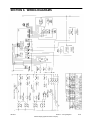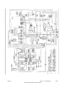
1
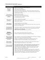
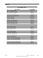
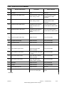
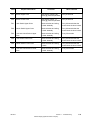
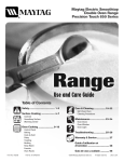
Maytag
Gemini™
Range
Service Manual
16010107
Issued 10/00
GENERAL SAFETY PRECAUTIONS
Information contained in this manual is intended for use by a qualified service technician. All
tests and repairs should be performed by a qualified service technician equipped with proper
tools and measuring devices. All component replacements should be made by a qualified
service technician using only factory approved replacement parts.
Improper assembly or adjustment may occur if service or repair is attempted by persons
other than qualified service technicians or if parts other than approved replacement parts are
used. Improper assembly or adjustment can create hazardous conditions.
There can be a risk of injury or electrical shock while performing services or repairs. Injury or
electrical shock can be serious or even fatal. Consequently, extreme caution should be taken
when performing voltage checks on individual components of a product. PLEASE NOTE:
Except as necessary to perform a particular step in servicing a product, the electrical power
supply should ALWAYS be disconnected when servicing a product.
Further, this appliance MUST be properly grounded. Never plug in or direct-wire an
appliance unless it is properly grounded and in accordance with all local and national codes.
See installation instructions that accompany the product for grounding this appliance.
USE ONLY GENUINE MAYTAG APPROVED FACTORY REPLACEMENT COMPONENTS.
IMPORTANT SAFETY NOTICE
THE INFORMATION INCLUDED IN THIS SERVICE
MANUAL IS INTENDED FOR THE USE OF
QUALIFIED SERVICE PERSONNNEL ONLY. ANY
ATTEMPT TO SERVICE THE APPLIANCE COULD
RESULT IN PERSONAL INJURY AND PROPERTY
DAMAGE.
DISCONNECT ELECTRICAL SUPPLY
BEFORE SERVICING.
IMPORTANT
ALL GROUNDING DEVICES MUST BE
RECONNECTED AND PROPERLY FASTENED.
GROUND PATH SPECIFICATIONS
GROUND PATH RESISTANCE:
INSULATION RESISTANCE:
0.1 Ω MAX.
250k Ω MIN.
ELECTRICAL CONNECTIONS
This range must be connected to a power source
that has the correct, voltage and frequency as
required by the rating plate. The rating plate can
be found on the back left side of control panel on
a lift up pivot bracket.
Wiring must be in accordance with local codes
and the National Electrical Code (NEC).
INTRODUCTION
The manual is printed in a loose format and is divided into sections relating to a general
group of components and/or service procedures. Each section is further subdivided to
describe a particular component or service procedure.
The subdividing of the subject matter, plus the loose leaf form, will facilitate the updating of
the manual as new revised components are added or new models are introduced.
Each page of the manual will be identified in the lower, left and right-hand corners, and as
new or revised pages are published, the manual can easily be updated by following the filing
instructions on the cover letter of the supplement.
This service manual is a valuable tool and care should be taken to keep it up-to-date by
promptly and proper filing of subsequent pages as they are used.
MODELS COVERED IN THIS MANUAL:
MER6770AAW
MER6770AAB
MER6770AAC
16010107
Introduction
©2000 Maytag Appliances Sales Company
i
16010107
Introduction
©2000 Maytag Appliances Sales Company
ii
CONTENTS
INTRODUCTION ................................................................................................................................. i
CONTENTS ....................................................................................................................................... iii
SECTION 1. GENERAL INFORMATION ......................................................................................1-1
SECTION 2. ELECTRICAL COMPONENTS & TESTING ............................................................2-1
SECTION 3. COMPONENT ACCESS ...........................................................................................3-1
EXPLODED VIEW .........................................................................................................................3-1
MAIN TOP .....................................................................................................................................3-2
ELEMENTS ...................................................................................................................................3-2
Ceran Element ........................................................................................................................3-2
Bake Element ..........................................................................................................................3-3
Broil Element ..........................................................................................................................3-3
Oven Sensor ...........................................................................................................................3-3
Oven Cavity Components (Electric) .....................................................................................3-4
Convect Fan Motor and Blade (Electric) ..............................................................................3-5
ELECTRONIC CLOCK AND OVEN CONTROL ...........................................................................3-6
INFINITE SWITCH (Current Sensing) .........................................................................................3-6
Signal Lights ...........................................................................................................................3-7
"Hot Surface" Light .................................................................................................................3-7
Oven Light Replacement .......................................................................................................3-7
HI-LIMIT THERMOSTAT ..............................................................................................................3-8
OVEN DOOR(S) ...........................................................................................................................3-8
UPPER DOOR ...............................................................................................................................3-9
LOWER DOOR ............................................................................................................................3-10
Lower Latch Assembly .........................................................................................................3-10
LOWER LATCH ASSEMBLY ......................................................................................................3-11
Oven Door Hinge ..................................................................................................................3-11
LEVELING LEGS .........................................................................................................................3-12
CONVENIENCE OUTLET (Canadian Models Only) ................................................................3-12
SPECIFICATIONS .......................................................................................................................3-12
OVEN RACKS .............................................................................................................................3-12
RACK POSITIONS ......................................................................................................................3-13
HALF RACK ACCESSORY ........................................................................................................3-13
SECTION 4. ELECTRICAL .............................................................................................................4-1
TOASTING CIRCUIT (Upper Oven Only) ...................................................................................4-1
OVEN CIRCUITS ...........................................................................................................................4-1
SURFACE ELEMENTS - CERAN .................................................................................................4-2
DUEL ELEMENT ...........................................................................................................................4-2
PROBE, SENSOR / BOTH OVENS ..............................................................................................4-2
HOT SURFACE LIGHTS ...............................................................................................................4-3
SURFACE INICATOR LIGHTS......................................................................................................4-3
TRANSFORMER, STEPDOWN (12V) .........................................................................................4-4
16010107
Contents
©2000 Maytag Appliances Sales Company
iii
SURFACE ELEMENT SWITCH ....................................................................................................4-4
DUAL ELEMENT SWITCH ...........................................................................................................4-4
ELECTRICAL CONNECTIONS/VOLTAGE ...................................................................................4-5
SECTION 5. TROUBLESHOOTING ..............................................................................................5-1
GEMINI DOUBLE OVEN CONTROLS .........................................................................................5-1
FAULT CODES ..............................................................................................................................5-2
RELAY BOARD .............................................................................................................................5-3
TROUBLESHOOTING GUIDE ......................................................................................................5-4
PARTS LIST ..................................................................................................................................5-6
FAULT IDENTIFICATIONS SUMMARY ......................................................................................5-7
SECTION 6. WIRING DIAGRAMS................................................................................................6-1
16010107
Contents
©2000 Maytag Appliances Sales Company
iv
SECTION 1. GENERAL INFORMATION
Bake: There will be two separate bake keys,
one for each oven. When the upper oven is
chosen there will be a rapid preheat
activated which turns both elements on. If
the lower oven is selected the elements will
cycle at the normal rate. The normal rates
for the bake functions in both ovens are: 6
seconds for the broil element, followed by 54
seconds for the bake element.
Broil: There will be two separate broil keys,
one for each oven. The HI broil function
controls the broil element at 100%, the LO
broil is controlled at 80% on time of a 60
second duty cycle. HI broil will be
maintained to reach a maximum
temperature of 550ºF, LO boil will be
maintained at a maximum of 450ºF.
Toasting: Available in upper oven only.
Toasting has a maximum allowable time of
10 minutes and maximum temperature of
550ºF. Toasting is only available when the
lower oven is not in use. If chosen during
lower oven operation the display will scroll
an information message regarding use.
16010107
Keep Warm: The keep warm function
controls only the bake element and is
available in the upper oven only. Allowable
temperature range is 145 to 190ºF.
Clean: Only one oven is permitted to be
cleaned at a time. Both ovens will lock
during clean cycle. The clean cycle controls
both the broil and the bake element, the broil
element is on 100% for the first 40 minutes
of the cycle followed by the bake element on
100% for the duration of the cycle. The bake
element is cycled once the clean
temperature of 865º is reached.
Motorized Door Lock: A 3 RPM motor is
used on the door lock assemblies, with each
assembly having a locked and unlocked
switch. The motor will only run when a
clean cycle is chosen and the door actuated
switch is in the closed position.
Section 1. General Information
©2000 Maytag Appliances Sales Company
1-1
16010107
Section 1. General Information
©2000 Maytag Appliances Sales Company
1-2
SECTION 2. ELECTRICAL COMPONENTS & TESTING
ELECTRICAL TEST EQUIPMENT
Description
Part Number
The equipment required to service Maytag
products depends largely upon the condition
you encounter. Locating a malfunction will
often require the use of electrical testing
equipment such as:
Analog Test Meter
20000005
Digital Watt/Amp/Volt/Ohm/
Temperature Meter
20000019
Clamp-On Ammeter
20000002
AC Voltage Sensor
20000081
Analog Test Meter
can be used to check for
open or closed circuits,
measure resistance, AC
and DC volts, and temperature.
Digital Watt/Amp/Volt/Ohm/Temperature
Meter
Measures power (wattage), AC/DC volts, AC/
DC amps, temperature (C & F) OHMS resistance, continuity and capacitance. Features
large LCD display w/backlight and analog
bar graph to show tendencies. Includes: AC
power adaptor for measuring wattage and
meter leads.
16010107
Clamp-On Ammeter
can be used to detect
shorts. Overloads on the
circuit breaker
or fuse can be
traced to either
the dryer or circuit
breaker by checking the dryer
current draw.
AC Voltage Sensor
can be used to alert you
if AC voltage is present so
proper safety precautions can
be observed. The tip of the sensor
will glow bright red, if voltage is between 110-600 volts AC.
Section 2. Electrical Components & Testing
©2000 Maytag Appliances Sales Company
2-1
16010107
Section 2. Electrical Components & Testing
©2000 Maytag Appliances Sales Company
2-2
SECTION 3. COMPONENT ACCESS
EXPLODED VIEW
16010107
Section 3. Component Description
©2000 Maytag Appliances Sales Company
3-1
As a general rule, the appliance should
ALWAYS be disconnected from power
source before servicing appliance or
replacing component parts. Failure to
disconnect the power increases the
likelihood that a servicing error or mistake
will result in serious or fatal injuries.
2. Remove the two screws securing the
main top to the frame.
3. Lift up slightly and slide the main top
forward to access the wire harness.
Disconnect the harness.
4. Lift the top off and lay aside securely with
under side up.
MAIN TOP
5. Remove the screws securing element to
main top.
To Raise Ceran Cooktop
When cool open the door and remove the
two screws securing the cook top to the
frame. Once the screws are removed raise
cook top and slide forward slightly. With the
cook top forward disconnect the wire
harness and remove the cooktop.
6. Disconnect wiring to element and
replace element.
7. Reverse procedure to reinstall.
To Remove Glass Top Assembly
1. Disconnect the appliance from power
source before servicing.
ELEMENTS
Ceran Element Cooktop
Cooking areas are identified by patterns in
the Ceran surface. The elements consist of
coil(s) contained in the element housing.
Power to the element (240 volts) is provided
and controlled by an infinite switch. Each
heating element is equipped with a
temperature limiter, which prevents heat
surges and ensures that the heating
elements will not overheat. The element and
temperature limiter is available as a
complete unit or individual parts.
When a cooking area is turned ON, the coil
element under the cook top will heat up and
glow. The element will cycle on and off to
maintain the heat setting. When the element
cycles on, it is normal to see a red glow
through the smooth top.
2. Remove two (2) screws securing glass
top to frame. The screws are located in
the front left and right corners with the
door open.
3. Grasp front edge of cooktop and slide out
slightly. With the top moved forward
disconnect the wiring harness.
4. Lift the top off the unit and lay aside
securely.
5. Reverse the procedure to reinstall.
Ceran Element
•
Left front and right rear element wattage:
208/240 volts @ 900/1200 watts.
Approximately 48Ω .
Note: It is normal for the element to cycle
when set on the high setting.
•
Left rear element wattage: 208/240 volts
@ 1580/2200 watts. Approximately 27Ω .
To Remove Element:
•
Dual element wattage: 208/240 volts @
1580/2200 watts. Approximately 27Ω for
the outer element. 208/240 volts @ 580/
750 watts. Approximately 73Ω for the
inner element.
1. Disconnect the appliance from power
source before servicing.
16010107
Section 3. Component Description
©2000 Maytag Appliances Sales Company
3-2
To Access Broil Element:
Bake Element
Element Wattage: 208/240 volts @ 2250/3000
watts. Approximately 19Ω
The bake function controls the Bake and
Broil heating elements. During a Bake cycle,
the Broil element will be on 6 seconds of a
60-second duty cycle, and then the Bake
element will be on the remaining 54
seconds. The Bake and Broil elements will
be staged with the exception of the rapid
preheat. In the rapid preheat, available when
the upper oven is used alone, the bake and
broil elements will be on at 100% until
temperature is reached. Once temperature
is reached, the elements will cycle as
outlined above.
Note: The Bake element will be the first
element to turn on at the beginning of any
conventional bake cycle.
To Access Bake Element:
1. Disconnect the appliance from power
source before servicing.
2. Remove lift off door for more
accessibility.
3. Remove four (4) screws securing bake
element to back of oven cavity.
4. Gently pull element through cavity wall
until terminals can be accessed.
5. Disconnect wiring.
6.
Remove/replace element as necessary.
7. Reverse procedure to reinstall.
1. Disconnect the appliance from power
source before servicing.
2. Remove lift off door for more
accessibility.
3. Remove broil support brackets (2) and
remove screws securing broil element to
back oven.
4. Gently pull element through cavity wall
until terminals can be accessed.
5. Disconnect wiring.
6. Remove/Replace element as necessary.
7. Reverse procedure to reinstall.
Oven Sensor
The oven sensor is located inside the oven
cavity, attached to the rear wall of the cavity.
As the oven temperature increases, the
resistance of the oven sensor increases. The
resistance is measured by the electronic
control to determine the oven temperature.
To Access Oven Sensor:
1. Disconnect the appliance from power
source before servicing.
2. Open oven door and remove two (2)
screws securing sensor to oven cavity.
Gently pull through cavity wall.
3. Disconnect the oven sensor at the
connector blocks and remove/replace as
necessary.
4. Reattach the connector blocks and
reassemble.
Broil Element
The broil function controls only the broil
element. The bake element is inactive
during a broil cycle. During a broil cycle, the
control will monitor the oven temperature
and cycle the broil element on and off to
obtain the selected temperature.
16010107
Section 3. Component Description
©2000 Maytag Appliances Sales Company
3-3
Oven Cavity Components (Electric)
Open or remove the oven door. The
following components are accessible:
•
•
•
•
•
Sensor
Broil Element
Convect
Fan
Racks
Oven Sensor
Broil Element
Convect Fan Cover
Bake Element
Convect
Fan
Cover
Bake Element
Convection Fan (Electric)
Remove six screws (as shown) from the
perimeter of the convection fan cover. This
will loosen the cover, but it cannot be
removed easily without positioning it to
clear the rack guides. Care should be used
when moving parts and tools around inside
the oven cavity to avoid marring or chipping
the procelain surfaces.
Screws
Screws
Screws
Three screws (shown) secure the convection
fan mounting plate, remove these, to allow
access to the motor and connectors.
Screws
Also shown here are the screws that secure the
bake and broil elements.
16010107
Section 3. Component Description
©2000 Maytag Appliances Sales Company
3-4
Convect Fan Motor and Blade (Electric)
Motor Connectors
Motor
After the convect fan mounting plate is
removed, motor connectors, motor, motor
mount and insulation is accessible. Motor
connectors are also exposed by removing
the back panel (see range back removal).
The convect fan blade is attached to the
motor’s “D” shaft using a hex set screw.
The fan blade must be loosened and taken off
the motor shaft before the motor can be
removed. The motor mounting screws are
found on the front side of the convect fan
assembly. When reassembling, be sure to
reinstall the small piece of insulation under the
motor mount. The insulation provides sound
dampening and prevents heat loss. When
reinstalling the convect fan blade, be sure that
the blade has adequate clearance at all points
around the mounting plate. The blade should
“stand off” approximately 1/8” with very little
apparent warping.
Motor Mount
Insulation
Mounting Screws
Hex Head Set Screw
Note: When reinstalling the convect assembly, be sure to
check that no loose insulation is visible in the fan area
or anywhere in the oven cavity.
16010107
Section 3. Component Description
©2000 Maytag Appliances Sales Company
3-5
ELECTRONIC CLOCK AND OVEN
CONTROL
To Gain Access To Electronic Oven Control
1. Disconnect the
appliance from
power source
before servicing.
2. Remove two screws
securing backguard
panel to the end caps.
3. Remove two (2) screws securing
backguard panel to backguard housing.
(Screws located between control panel
and main top).
4. Lift backguard panel up, tilt forward, and
lay panel on protected surface of main
top for servicing.
5. Remove two (2) screws securing controlmounting plate to backguard.
6. Remove four (4) screws securing control
to control mounting plate.
removes voltage from the heating element.
Control is attained by regulating the ratio of
the time between the opening and closing of
the contacts. This is usually referred to as
input percentage and is controlled by a cam,
which can provide virtually any infinitely
adjustable performance. This performance
is assured when the switch is subjected to
elevated ambient temperatures through
automatic temperature compensation.
The infinite switch stems are color coded for
identification. The silver colored stem
controls the left front and right rear element,
the silver colored stem with a red dot
controls the left rear, and the brass colored
stem controls the right front element.
Amperage is rated at 3-15.5A range +/- 10%.
Note: When replacing the infinite switch,
the switch must be matched to the element.
To Access Control:
1. Disconnect the appliance from power
source before servicing.
2. Remove control knobs.
7. Disconnect wiring and remove/replace
control.
3. Remove two screws from backguard
panel securing panel to housing.
8. Reverse procedure to replace.
4. Remove two screws securing backguard
panel to end cap.
INFINITE SWITCH (Current Sensing)
5. Lift backguard panel up, tilt forward, and
lay panel on protected surface on main
top for servicing.
This unit is equipped with controls that
provide an infinite choice of settings from
LOW to HIGH. The control can be set on any
of the numbered settings. To operate, push
in and turn control knob to the desired
setting.
Note: The infinite switch is a current
sensing switch.
6. Remove two (2) mounting screws
securing infinite switch to backguard
panel.
7. Disconnect wiring and remove/replace
control.
8. Reverse procedure to replace.
The infinite switch is a rotary switch, which
controls the power dissipated by a heating
element. A heater-bimetal opens and closes
the cycling contacts, which applies and
16010107
Section 3. Component Description
©2000 Maytag Appliances Sales Company
3-6
Signal Lights
Oven Light Replacement
Range is equipped with two signal lights to
indicate when a surface element is on. The
light will remain on until the element is
turned off. After a cooking operation, be
sure element and signal light is off.
The oven light used on the Gemini is a 12
volt 10 Watt Halogen bulb. The light
automatically comes on when the door is
opened or activation may occur via the light
pad when the door is closed. The light will
not operate during a clean cycle. The oven
light will automatically come on one minute
before the end of a clock controlled cooking
operation.
The signal lights are located on the
backguard panel and may be accessed from
the backside of the panel when removed.
The red indicator lens pop in and out, and
the light slides into a lock position. Reverse
the procedure to remove.
To Replace Oven Light Bulb:
1. Disconnect power to the range.
“Hot Surface” Light
2. Open oven door and locate oven light.
The Gemini Range is equipped with a Hot
Surface Light. This red light will turn on to
indicate that the cooking area is hot and will
remain on until the area has cooled.
3. Remove the lens cover to gain access to
bulb.
The switch is located in the front center of
the burner box, and may be accessed by
removing the main top.
4. Carefully remove the old bulb by pulling
straight out of ceramic base.
To Access Hot Surface Light:
NOTE: To avoid damaging the bulb and
decreasing the life of the bulb, do not touch
the bulb with bare hands or fingers. Hold
with a cloth or paper towel.
1. Disconnect the appliance from power
source before servicing.
5. Push new bulb prongs straight into small
holes of ceramic base.
2. Open oven door and remove the screws
securing the main top to the frame.
6. Replace bulb cover by snapping into
place.
3. Slide the top forward and disconnect the
wire harness.
7. Reconnect power to range and reset
clock.
4. Lift the top off and lay on a protected
surface with under side up.
5. Release the tabs securing the switch to
the top. Once the tabs are released the
switch can be removed.
6. Reverse procedure to replace.
Bulb specifications
G4 Type Halogen Bi-Pin 10 w -12V
16010107
Section 3. Component Description
©2000 Maytag Appliances Sales Company
3-7
HI-LIMIT THERMOSTAT
CAUTIONS:
The HI-Limit Thermostat is mounted to
range main back. The purpose of this
thermostat is to break line voltage to oven
control in case of a runaway temperature.
Range may be removed from cabinetry for
rear serviceability.
• Do not attempt to open or close door
or operate oven until door is properly
replaced.
• Hinge arms are spring mounted and
will slam shut if accidentally hit.
Never place hand or fingers between
the hinges and the front oven frame.
You could be injured if hinge snaps
back.
Both the upper and lower oven doors are
removable.
To Remove Lift-Off Door:
Contacts normally closed
Close Temperature - 250 ± 11ºF
Open Temperature - 300 ± 8ºF
Open door to stop position. In stop position
door is open approximately 4”. Grasp door
as illustrated. Lift up evenly until door clears
the hinge arms.
Thermostat Replacement
1. Disconnect the appliance from power
source before servicing.
2. Slide unit out of installation.
3. Remove screws securing main back
shield and remove shield.
4. Remove two (2) screws securing
thermostat to range main back.
DO NOT USE DOOR HANDLE TO LIFT
DOOR.
5. Disconnect wiring.
To Replace:
6. Replace in reverse order.
1. Grasp door at each side.
OVEN DOOR(S)
Do not place excessive weight on an open
oven door or stand on an opened door as, in
some cases, it could cause the range to tip
over, breakage of the door, or serious injury.
16010107
2. Align slots in the door with the hinge
arms on the range.
3. Slide the door down onto the hinge
arms until the door is completely
Section 3. Component Description
©2000 Maytag Appliances Sales Company
3-8
seated on the hinges. Push down on
the top corners of the door to
completely seat door on hinges. Door
should not appear crooked.
NOTE: The oven door on a new range
may feel “spongy” when it is closed.
This is normal and will decrease with
use.
To Disassemble Door:
5. Slide the doorframe and glass off liner
from the bottom.
6. Remove four (4) screws securing the
door handle to the door liner. (Two on
the sides and two in front).
7. Remove two (2) screws securing door
baffle to liner.
8. Remove four (4) screws securing door
baffle to window pack. Remove baffle.
1. Open door to the stop position and lift
door off hinges. Remove door and lay
on protected surface, liner side up.
9. Remove insulation wrap.
2.
10. Remove four (4) screws securing window
pack to liner. Window pack comes out as
an assembly.
Remove three (3) screws securing the
doorframe to the liner at the bottom.
3. Remove two (2) side screws securing
doorframe to door liner.
4. Remove four (4) screws securing the
door trim at the top.
11. Door gasket can be replaced without
door being disassembled by pulling
gasket out of bottom insert of door. The
gasket is secured with clips inserted into
door liner.
UPPER DOOR
16010107
Section 3. Component Description
©2000 Maytag Appliances Sales Company
3-9
LOWER DOOR
To Replace Lock Assembly
7. Remove two (2) screws securing lock
assembly to frame.
1. Disconnect the appliance from power
source before servicing.
8. Slide assembly out.
2. Open oven door or remove for
convenience.
9. Reverse procedure to reinstall.
3. Remove main top and slide forward.
Disconnect wire harness. (See Top
Removal).
Lower Latch Assembly
1. Disconnect the appliance from power
source before servicing.
4. Lift top off and lay aside securely.
5. Remove two (2) screws securing lock
assembly to oven frame in front.
2. Remove main top assembly as described
previously and lay aside securely.
6. Disconnect wiring.
16010107
Section 3. Component Description
©2000 Maytag Appliances Sales Company
3-10
3. Remove main top and slide forward.
Disconnect wire harness. (See Top
Removal).
Note: Make sure the insulation is back in
place when finished. Failure to do so will
result in hot spots and poor baking
complaints.
LOWER LATCH ASSEMBLY
5. Reattach band to the bottom of frame.
1. Disconnect the appliance from power
source before servicing.
6. Reconnect wiring to the lock switches.
7. Reinstall the side panel.
2. Remove main top as outlined
in main top removal.
8. Reinstall the rear panel.
3. Remove the screws
securing the side
panel at the top and
back of frame.
9. Reinstall the main top.
4. Remove the screws
securing the rear
panel to frame. Remove rear panel.
The unit will have to be pulled away from the
cabinetry to remove/replace door hinges.
Oven Door Hinge
To Access/Replace Oven Door Hinges:
5. Slide side panel away from the frame at
rear and lift out of the slots in front.
Remove side panel.
1. Disconnect the appliance from power
source before servicing.
6. Release the bands, securing the
insulation wrap, at the bottom.
2. Remove main top assembly as described
previously and lay aside securely.
7. Slide the insulation wrap back.
3. Remove oven door assembly as
previously described and lay aside
securely.
Note: This will aid in guiding the latch
assembly in and out.
8. Disconnect the wiring from the lock
switches at the rear.
9. Slide the latch assembly out from the
rear.
4. Remove the screws securing side panel
at the top and back of frame.
5. Remove the screws securing the rear
panel to frame.
6. Slide the side panel away from the frame
at rear and lift out of the slots in the
front. Remove panel.
To reinstall:
1. Slide latch assembly in from the rear.
2. Guide assembly to front using the side
access.
3. Make sure the screw holes of the
assembly line up with the screw holes in
the frame.
7. Remove two (2) screws securing hinge to
front frame flange.
8. Complete hinge assembly may be
removed.
9. Reverse procedure to reinstall.
4. Reinsert the screws.
16010107
Section 3. Component Description
©2000 Maytag Appliances Sales Company
3-11
The convenience outlet circuit breaker may
trip if the small appliance plugged into it
exceeds 10 amps. To reset the circuit
breaker, press the switch located on the
lower edge of the backguard. (See figure
below).
OVEN DOOR HINGE
Note: The door hinges are colored coded
for ease in installation. The upper spring
hook is gold and the lower spring hook is
white.
LEVELING LEGS
SPECIFICATIONS
Some floors are not level. For proper
baking, your range must be level.
Overall Dimensions:
Leveling legs are located on each corner of
the base of the range.
Place a level horizontally on an oven rack
and check front-to-back and side-to-side.
Level by turning the legs.
Height (in./cm) 46 3/4 /118.7
Width (in./cm) 29 7/8 /76
Depth Excluding Handle (in./cm) 26 1/8 /66
Weight (lbs./kg.) 225/102
Total Connected Load (kw @ 24V/208V)
10.4/7.8
OVEN RACKS
CAUTIONS:
• Do not attempt to change the rack
position when the oven is hot.
All racks are designed with a lock-stop edge.
CONVENIENCE OUTLET
(Canadian Models Only)
Upper Oven
The convenience outlet is located on the
lower left side of the backguard. It is useful
for small appliances such as waffle irons.
When using the outlet be sure the appliance
cord does not rest on or near the surface
element. If the surface element is turned on,
the cord and outlet wil be damaged.
16010107
•
Is equipped with one rack and rack
position.
•
When pulling the
upper oven rack out
to remove or check
food, grasp the top
edge of the rack.
Section 3. Component Description
©2000 Maytag Appliances Sales Company
3-12
Lower Oven
•
Is equipped with two RollerGlide™ racks.
To remove oven racks:
•
Pull rack straight out until it stops at the
lock-stop position; lift up on the front of
the rack and pull out.
•
For lower oven racks, pull both the rack
glide and rack base out together.
Multiple Rack Cooking:
Two Rack: Use rack position 2 and 4, or 1
and 4.
HALF RACK ACCESSORY
To replace oven racks:
•
Place rack on the rack support in the
oven; tilt the front end up slightly; slide
rack back until it clears the lockstop
position; lower front and slide back into
the oven.
A half rack, to increase oven capacity, is
available as an accessory. It fits in the left,
upper portion of the oven and provides
space for a vegetable dish when a large
roaster is on the lower rack. Contact your
Maytag dealer for the "HALFRACK"
Accessory Kit or call 1-800-688-8408.
RACK POSITIONS
Rack 4: Use for two-rack baking.
Rack 3: Use for most baked goods on a
cookie sheet or jelly roll pan, layer
cakes, fruit pies, or frozen
convenience foods, and for most
broiling.
Rack 2: Use for roasting small cuts of meat,
casseroles, baking loaves of bread,
bundt cakes or custard pies, and
two-rack baking.
Rack 1: Use for roasting large cuts of meat
and poultry, frozen pies, dessert
souffles or angel food cake, and
two-rack baking.
16010107
Section 3. Component Description
©2000 Maytag Appliances Sales Company
3-13
NOTES
16010107
Section 3. Component Description
©2000 Maytag Appliances Sales Company
3-14
SECTION 4. ELECTRICAL
TOASTING CIRCUIT (Upper Oven Only)
OVEN CIRCUITS
To Access Bake Element: Upper Oven Only
To Access Broil Element:
1. Disconnect power from unit before
servicing.
1. Disconnect power from unit before
servicing.
2. Remove door for more accessibility.
2. Remove door for more accessibility.
3. Remove 2 screws securing bake element
to back of oven cavity.
3. Remove broil support brackets (2), and
remove 2 screws securing broil element
to back of oven.
4. Gently pull element through cavity wall
until terminals can be accessed. Use
Caution: Space is limited.
5. Disconnect wiring.
4. Gently pull element through cavity wall
until terminals can be accessed.
Use Caution: Space is limited.
6. Remove/replace element as necessary.
5. Disconnect wiring.
7. Reverse procedure to reinstall.
6. Remove/Replace element as necessary.
7. Reverse procedure to reinstall.
16010107
Section 4. Electrical
©2000 Maytag Appliances Sales Company
4-1
SURFACE ELEMENTS - CERAN
Verify there is proper voltage applied to the
oven (the range may have blown a fuse or
circuit breaker). A quick check is to see if the
other elements heat. If not, check the
voltage at the electrical outlet and check to
see that the power cord is wired correctly.
ELECTRICAL RATINGS: 240VAC 2200W TOTAL
750W INNER RING
1450 OUTER RING
COLD RESISTANCE:
74.6 Ohms (INNER)±5
38.6 Ohms (OUTER)±5
LIMITER TYPE:
ELECTRICAL RATINGS OF LIMITER CONTACTS
LIMITER CIRCUIT 10 AMP AT 250 VAC
LIMITER CIRCUIT 7.0 AMPA T 380 VAC
HOT LIGHT CIRUCIT 1.0 AMP AT 380 VAC
To Check Surface Element:
1. Disconnect unit from power source
2. Remove main top by removing screws
securing top to burner box and lay aside
securely.
3. Visually check the element for evidence
of damage or shorting. Then check the
element for continuity with an ohmmeter
connected to the element terminals.
With ohmmeter set at RX1, resistance
will normally be below 28 ohms, large
and 48 ohms, small. If the element
shows no continuity or extremely high
resistance, it should be replaced.
4. With power to the unit disconnected, set
the control switch for this element on the
high setting. With a voltmeter set on 250
or 300 volt scale, re-apply power and
check for voltage at the surface element
terminal block, then check the surface
element.
Each heating element is equipped with a
temperature limiter which prevents heat
surges and ensures that the heating
elements will not overheat.
DUEL ELEMENT
The cooking surface is equipped with a dual
element located in the right front position.
To operate, push in on the controlknob and
turn to the left to control the large element,
or push in and turn to the right to control the
small element.
PROBE, SENSOR / BOTH OVENS
Oven Sensor
The oven sensor is located inside the oven
cavity, attached to the rear wall of the cavity.
As the oven temperature increases, the
resistance of the oven sensor increases. The
resistance is measured by the electronic
control to determine the oven temperature.
The "Hot Surface" light will come on
indicating when ceran surface is 150ºF ±
50ºF. The Hi-Limit which shuts burner off at
1050ºF ± 60ºF.
16010107
Section 4. Electrical
©2000 Maytag Appliances Sales Company
4-2
To check oven sensor:
1. Access sensor wires as outlined under
sensor removal.
2. Set meter to RX1000 Scale.
3. Check for the following:
TEM PERATURE
RESISTANCE
100 Degrees F
1143 Ohm s
200 Degrees F
1350 Ohm s
300 Degrees F
1553 Ohm s
350 Degrees F
1654 Ohm s
400 Degrees F
1753 Ohm s
500 Degrees F
1949 Ohm s
600 Degrees F
2142 Ohm s
700 Degrees F
2331 Ohm s
800 Degrees F
2516 Ohm s
900 Degrees F
2697 Ohm s
1000 Degrees F
2874 Ohm s
HOT SURFACE LIGHTS
SURFACE INDICATOR LIGHTS
Each element has a HOT SURFACE indicator
light. A light will be illuminated when the
matching cooking area is hot. It will remain
on, even after the control is turned off, until
the area has cooled. They are located at the
front center of the cooktop.
There is an indicator light by each pair of
control knobs. When one or both of the
surface control knobs is turned on, the light
will turn on. The light will turn off when the
surface element(s) is turned off.
16010107
Section 4. Electrical
©2000 Maytag Appliances Sales Company
4-3
TRANSFORMER, STEPDOWN (12V)
Electrical Ratings:
Input Voltage: 120 Volts
Operating Frequency 60 Hz
Output Voltage: 7-12 VAC
at 10W Load 11.6 ± .2 VAC
at 20W Load 11.1 ± .3 VAC
SURFACE ELEMENT SWITCH
DUAL ELEMENT SWITCH
16010107
Section 4. Electrical
©2000 Maytag Appliances Sales Company
4-4
ELECTRICAL CONNECTIONS/VOLTAGE
Range Amperage:
The total range wattage is stamped on
model plate in kilowatts, (kilowatt = 1,000
watts) to determine amperage for fuse or
circuit breaker:
•
Check incoming voltage at range main
terminal block (pigtail) see illustration.
•
Divide voltage into total wattage.
Example: 10. K.W. (stamped on model
plate) X 1,000 = 10,000 watts. Voltage (at
terminal block) is 240 VAC. 10,000 ÷ 240
= 41.6 (AMPS). This indicates a fuse or
circuit breaker with a rating of slightly
over 41 AMPS would be needed.
The range is connected to an outlet through
an approved range connector (pigtail)
fastened securely to the terminal block with
proper strain relief at the range and a three
or four pronged plug at the opposite end.
With range connected to electricity by
means of an approved range connector
(pigtail) voltmeter reading between L1 and
L2 should be approximately 240 VAC.
Voltmeter reading between terminal
NEUTRAL and terminal LINE 1 should be
approximately 120 VAC. Voltmeter reading
between NEUTRAL and LINE 2 should be
approximately 120 VAC. Center terminal of
main terminal block is netural. Range frame
is connected to neutral at this point by a
ground strap and screw.
REMEMBER: MOBILE HOMES AND SOME
LOCAL CODES DO NOT PERMIT
GROUNDING THROUGH NEUTRAL.
HENCE, 4-WIRE SERVICE MUST BE
PROVIDED FOR SUCH INSTALLATIONS.
ALL OTHERS PERMIT 3-WIRE SERVICE, USE
COPPER WIRE ONLY. AFTER
INSTALLATION, ENSURE TIGHTNESS OF
ALL ELECTRICAL CONNECTIONS AND
REPLACE ALL COVERS.
NOTE: For cord (pigtail) replacement, only
a power supply cord kit rated at 240 volts
minimum, 40 amperes, with closed loop
terminals and marked for use with ranges
shall be used.
16010107
Section 4. Electrical
©2000 Maytag Appliances Sales Company
4-5
NOTES
16010107
Section 4. Electrical
©2000 Maytag Appliances Sales Company
4-6
SECTION 5. TROUBLESHOOTING
GEMINI DOUBLE OVEN CONROLS
The control is activated via a membrane switch which contains the function pads and 10 key
digi-pad. Data can be entered either by choosing the function and entering a value or by
choosing the function and using the Auto Set pad. Values for the Auto Set pad are listed
below.
1ST
PRESS
ºF / ºC
2ND
PRESS
3RD
PRESS
4TH
PRESS
5TH
PRESS
6TH
PRESS
7TH
PRESS
Bake
350/175
375/190
400/205
425/215
450/230
475/245
325/160
Broil
HI
550/290
LO
450/230
Convect*
325/160
350/175
375/190
400/205
425/215
450/230
475/245
Clean Tim e
3:00 Hrs.
4: 00 Hrs.
2:00 Hrs.
Toasting * *
4:00 M in.
4: 10 M in.
4:20 M in.
4: 30 M in.
4:40 M in.
4: 50 M in.
5:00 M in.
10:00
Keep Warm
170/75
COOKING
FUNCTION
* If equipped.
* * Toasting has a m axim um allow able tim e of 10 m inutes, available in upper oven only.
16010107
Section 5. Troubleshooting
©2000 Maytag Appliances Sales Company
5-1
FAULT CODES
Fault Codes, Displayed in Upper Time Digits:
There are three major fault codes that will be
displayed in the time digits of the upper
clock display to the left of the colon. Minor
fault codes are displayed in the time digits to
the right of the display colon, these are used
to direct the technician to more specific
locations for diagnosis. Major fault codes
are as follows:
F1: Temperature runaway. Membrane
switch shorted. Alarm is continuous, if
cancel key is pressed alarm will stop, if fault
still present alarm will repeat. If membrane
switch is disconnected the alarm will only
sound for 30 seconds and stop.
Correction: Test membrane switch and oven
sensor, if OK, replace control.
F3: Open or shorted sensor. The cancel key
resets the control and stops the alarm. If
fault is still present it will reactivate the
alarm when a cook mode is chosen.
Correction: Check sensor and wiring for
shorted or open circuit.
F9: Door lock error. Check the status of the
door lock switches. Unlocked and locked
switches must be in sequence, unlocked
closed during normal operation and locked
open. The opposite is true during a clean or
locked state.
Timer Functions: The timer operates
independently of all other functions. There
are two timer functions. Timer 1 and Timer
2. The countdown time in the upper VFD
can be toggled by pressing the clock and
timer 1 keys.
Off/Cancel: Will cancel any oven operation
by pressing the appropriate cancel key for
the respective oven. Cancel will not effect
the timer or clock functions.
Oven Temperature Adjust: Bake
temperature can be adjusted by pressing
Bake in either upper or lower oven, entering
a temperature of 550ºF, then hold bake key
for 3 seconds. Auto set is used to adjust the
temperature either + / - 35ºF in 5º F
increments
(+ / - 21ºC, in 3ºC increments).
Control Lockout: The control can be Locked
Out by pressing Setup and then 4. When
locked "Control Locked" will be displayed and
scroll twice. Press Auto Set to toggle
between Locked and Unlocked. The control
locktout will not lock out the timer, clock,
setup options or oven light.
Test Mode: Accessed by holding Cancel and
Broil keys down for 3 seconds within 5
minutes of power up. The test mode cannot
be accessed if the oven temperature is above
400ºF. When test mode is activated all digits
will display "-". To exit the test mode press
Cancel or auto exit occurs 16 seconds after
last key pressed.
KEY PRESSED
RELAY or ACTION
ACTIVATED
Upper Bake
Upper Bake Elem ent
Low er Bake
Low er Bake Elem ent
Upper Broil
Upper Broil Elem ent
Low er Broil
Low er Broil Elem ent
Convection Bake*
Convection fan*
Upper Oven Light
Upper Oven Light
Low er Oven Light
Low er Oven Light
Upper Clean
M otorized Door Lock, Upper
Low er Clean
M otorized Door Lock, Low er
Stop Tim e
Beeper
Cook Tim e
Display error codes
Clock
Display all tim e digits
*Convection Fan Relay: If equipped, the
convection fan relay will activate the convect
fan motor when the oven door is closed. In
a convect mode the relay will shut off the
convect fan when the door is opened.
16010107
Section 5. Troubleshooting
©2000 Maytag Appliances Sales Company
5-2
Engineering Mode: Used to view the actual
oven temperature for both ovens at all times,
even when an oven function is active. This
mode will also display the current fault code
for 5 seconds in the time digits. Enter the
engineering mode by pressing the Bake Key
of either oven, enter a bake temperature of
100ºF, then hold Bake down for 3 seconds
within 30 seconds of initial Bake press. The
mode can be exited by pressing Cancel.
Oven Light: Oven light key toggles the oven
light on and off. Oven light is deactivated
during a clean cycle.
Dual Line Break Relay: Canadian Models
Only. Relay wil be a 17 amp, 240 VAC
minimum contact rating. There will also be
a 5.6 Ohm resistor and a connection to the
normally open contact on Canadian models
to allow for "Hi-Pot" testing at the factory.
50/60 Hertz Option: Control automatically
senses cycle rate of supply line.
Demo Mode: The control can be placed in a
sales demo mode by pressing Bake and
Cancel keys for 3 seconds. The demo mode
can be exited by pressing any key. This
mode will activate the display as if the unit is
operating without energizing the heating
elements.
RELAY BOARD
Relay Board: The relay board will be equipped to operate the following outputs. Some
shown can be optional. The Double Line Break (DLB) is located remotely, off board from the
main control.
RELAY OUTPUTS
CUR
(A
Lower Broil - 3600 Watts
240
Lower Bake - 2585 Watts
240
1
Convect*
120
0
Upper Broil - 2200 Watts
240
9
Upper Bake - 1800 Watts
240
9
Upper Oven Light
12
Lower Oven Light
12
Upper Door Lock
120
0
Lower Door Lock
120
0
Upper Double Line Break
240
Lower Double Line Break
240
SURFACE ELEM ENT VALUES
16010107
VOLTAGE
(Volts AC)
W
VOLTS
Left Front/Right Rear
240
1
Left Rear
240
2
Right Front/Dual
240
750 inne
Section 5. Troubleshooting
©2000 Maytag Appliances Sales Company
5-3
TROUBLESHOOTING GUIDE
Check these points if . . .
•
•
•
•
•
•
Part or all of the
appliance does
not work.
○
○
○
○
○
○
○
○
○
○
○
○
○
○
○
○
○
○
○
○
○
○
○
○
○
○
○
○
○
○
○
○
○
○
○
○
○
○
○
○
○
○
○
○
○
○
○
○
○
○
Baking results
differ from
previous oven.
16010107
○
○
○
○
○
○
○
○
○
○
○
○
○
○
○
○
○
○
○
○
○
○
○
○
○
○
○
○
○
○
○
○
○
○
○
○
○
○
○
○
○
○
○
○
○
○
○
○
○
○
○
○
○
○
○
○
○
○
○
○
○
○
○
○
○
○
○
○
○
○
○
○
○
○
○
○
○
○
○
○
○
○
○
○
○
○
○
○
○
○
○
○
○
○
○
○
○
○
○
○
○
○
○
○
○
○
○
○
○
○
○
○
○
○
○
○
○
○
○
○
○
○
○
○
○
○
○
○
○
○
○
○
○
○
○
○
○
• Check the oven temperature selected. Make sure oven is preheated when
recipe or directions recommended preheat.
• Check rack positions.
• Use correct pan. Dark pans produce dark browning. Shiny pans produce
light browning. See "Cooking Made Simple" booklet for more information on
bakeware.
• Check the use of foil in the oven. Never use foil to cover an entire oven rack.
Place a small piece of foil on the rack below the pan to catch spillovers.
• Check pan placement. Stagger pans when using two racks. Allow 1-2 inches
between pan and oven walls.
• Make sure the oven vent has not been blocked.
• Check to make sure range is level.
Baking results are
not what you
expected.
○
○
1. Tiny screatches or abrasions.
• Check to make sure cooktop and pan bottom are clean. Do not slide glass
or metal pans across top. Make sure pan bottom is not rough. Use the
recommended cleaning agents.
2. Metal marks.
• Do not slide metal pans across top. If metal marks appear, clean when cool
with Cooktop Cleaning Creme.
3. Brown streaks and specks.
• Spills not removed promptly. Wiping with soiled cloth or sponge. Pan
bottom not clean.
4. Areas with a metallic sheen.
• Mineral deposits from water and food.
5. Pitting or flaking.
• Sugary boilovers that were not removed promptly.
Glass-Ceramic
surface shows
wear.
○
to be sure plug is securely inserted into receptacle.
or re-set circuit breaker. Check or replace fuse.
power supply.
if surface and/or oven controls have been properly set.
if oven door is unlocked after a self-clean cycle.
if oven is set for a delayed cook or clean program.
NOTE: On Canadian models, the glass-ceramic cooking surface will not
operate during a self-clean cycle.
• Check to be sure plug is securely inserted into receptacle.
• Check or re-set circuit breaker. Check or replace fuse.
• Check power supply.
• Check if surface and/or oven controls have been properly set.
• Check if oven is set for a delayed oven operation.
• Upper oven may be in a toasting operation. Lower oven will operate when the
toasting operation is completed.
Surface or oven
elements fail to
operate or heat
food.
○
○
Check
Check
Check
Check
Check
Check
○
○
○
○
○
○
○
○
○
○
○
○
○
○
○
○
○
○
○
○
○
○
○
○
○
○
○
○
○
○
○
○
○
○
○
○
○
○
○
○
○
○
○
○
○
○
○
• Temperatures often vary between a new oven and an old one. As ovens age,
the oven temperature often "drifts" and may become hotter or cooler.
NOTE: It is not recommended to adjust the temperature if only one or two
recipes are in question.
Section 5. Troubleshooting
©2000 Maytag Appliances Sales Company
5-4
○
TROUBLESHOOTING GUIDE Continued...
Check these points if . . .
•
•
•
•
•
Food is not
broiling
properly.
○
○
○
○
○
○
○
○
○
○
○
○
○
○
○
○
○
○
○
○
○
○
○
○
○
○
○
○
○
○
○
○
○
○
○
○
○
○
○
○
○
○
○
○
○
○
○
○
○
○
○
○
○
○
○
○
○
○
○
○
○
○
○
○
○
○
Moisture
condensation
collects on oven
window.
○
○
○
○
○
○
○
○
○
○
○
○
○
○
○
○
○
○
○
○
○
○
○
○
○
○
○
○
○
○
○
○
○
○
○
○
○
○
○
○
○
○
○
○
○
○
○
○
○
○
○
○
○
○
○
○
○
○
○
○
○
○
○
○
○
○
○
○
○
○
○
○
○
○
○
○
○
○
○
○
○
○
○
○
○
○
○
○
○
○
○
○
○
○
○
○
○
○
○
○
○
○
○
○
○
○
○
○
Food too close to element.
Broiler insert covered with aluminum foil.
Trim excess fat from meat prior to broiling.
A soiled broiler pan was used.
○
○
○
○
○
○
○
○
○
○
○
○
○
○
○
○
○
○
○
○
○
○
○
○
○
○
○
○
○
○
○
○
○
○
○
○
○
○
○
○
○
○
○
○
○
○
○
○
○
○
○
○
○
○
○
○
○
○
○
○
○
○
○
○
○
○
○
○
○
○
○
○
○
○
○
○
○
○
○
○
○
○
○
○
○
○
○
○
○
○
○
○
○
○
○
○
○
○
○
○
○
○
○
○
○
○
○
○
○
○
○
○
○
○
○
○
○
○
○
○
○
○
○
○
○
○
○
○
○
○
○
○
○
○
○
○
○
○
○
○
○
○
○
○
○
○
○
○
○
○
○
○
○
○
○
○
○
○
○
○
○
○
○
○
○
○
○
○
○
○
○
○
○
○
○
○
○
○
○
○
○
○
○
○
○
○
○
○
○
○
○
○
○
○
○
○
○
○
○
○
○
○
○
○
○
○
○
○
○
○
○
○
○
○
○
○
○
○
○
○
○
○
○
○
○
○
○
○
○
○
○
○
○
○
○
○
○
○
○
○
○
○
○
○
○
○
○
○
○
• When high moisture foods are cooked in the upper oven, steam may be
visable coming form the vent area. This is normal.
○
"F" plus a number
and the message.
16010107
○
• This is normal for a new range and will disappear after a few uses. Initiating a
clean cycle will "burn off" the smells more quickly.
• Turning on a ventilation fan will help remove the smoke and/or odor.
• Excessive food soils on the oven bottom. Use a self-clean cycle.
Steam comes
from vent area.
○
○
• This is normal when cooking food high in moisture.
• Excessive moisture was used when cleaning the window.
There is a strong
odor or light
smoke when oven
is turned on.
○
○
• Oven interior is still hot. Allow about one hour for the oven to cool after the
completion of a self-clean cycle. The door can be opened when the LOC
indicator word is not displayed.
• Both ovens will lock when either oven is cleaned.
Oven Door will
not unlock after
self-clean cycle.
○
○
• Longer cleaning time may be needed.
• Excessive spillovers, especially sugary and/or acid foods, were not removed
prior to the self-clean cycle.
Oven did not
clean properly.
○
○
• Check if controls are set properly.
• Check to make sure the cycle is not set for a delayed start.
• Check if door is closed.
Oven will not
self-clean.
○
○
•
•
•
•
Oven smokes
excessively during
broiling.
○
Check if oven controls have been properly set.
Check oven rack positions.
Broil element was not preheated.
Aluminum foil was incorrectly used. Never line the broiler insert with foil.
Oven door was closed during broiling. Leave the door open to the first stop
position (about 4 inches).
○
○
○
○
○
○
○
○
○
○
○
○
○
○
○
○
○
○
○
○
○
○
○
○
○
○
○
○
○
○
○
○
○
○
○
○
○
○
○
○
○
○
○
○
• This is called a fault code. If a fault code appears in the display and beeps
sound, press the CANCEL pad. If the fault code and beeps continue,
disconnect power to the appliance. Wait a few minutes, then reconnect
power. If fault code and beeps still continue, disconnect power to the
appliance and call an authorized servicer.
• If the oven is heavily soiled, excessive flare-ups may result in a fault code
during a clean cycle. Press CANCEL pad and allow the oven to cool for one
hour, then reset the clean cycle. If the fault code and beeps still continue,
disconnect power to the appliance and call an authorized servicer.
Section 5. Troubleshooting
©2000 Maytag Appliances Sales Company
5-5
PARTS LIST
REPLACEMENT PARTS
PART NAME
PART NUMBER
Main Top Assembly (Black)
74004515
Main Top Assembly (White)
74004516
Hinge, Oven Door (EURO)
74003968
Hinge, Oven Door Upper Gemini
74004523
Switch, Infinite 2600
7403P239-60
Switch, Dual Element
74002144
Element, Broil 3600W/6Pass
74003040
Element, Bake Upper Gemini
74004105
Element, Broil Upper Gemini
74004106
Element, Bake Lower Oven
74004107
Element, Ribbon 1200W
74001011
Element, Ribbon 2200W
74001012
Element, Ceran Dual
74004556
Lamp, Assembly Halogen
74004521
Transformer, Stepdown 12V
74004545
Probe, Sensor/Both Ovens
74003390
Clock, E-Trnc-Elc D/O M/T
74004542
Overlay, Clock Gemini White Maytag
74004544
Overlay, Clock Gemini Black Maytag
74004543
Latch, Door Lock Motor 3RPM Upper
74004528
Latch, Door Lock Motor 3RPM Lower
74004519
16010107
Section 5. Troubleshooting
©2000 Maytag Appliances Sales Company
5-6
FAULT IDENTIFICATION SUMMARY
Fault
Suspect Failure Area
Correction
When Checked
F0-0
No Fault
None
Anytime
F1-1
Runaway Cook Upper Oven
Check the sensor 1050-1100
ohms, wiring, control
Every 6 seconds that the
control sees the latch
unlocked.
F1-2
Runaway Cook Lower Oven
Check the sensor 1050-1100
ohms, wiring, control
Every 6 seconds that the
control sees the latch
unlocked
F1-3
Runaway Clean Upper Oven
Temperature above 650º F.
Check the sensor and
control
Every 6 seconds that the
control sees the latch locked
F1-4
Runaway Clean Lower Oven
Temperature above 650º F.
Check the sensor and
control
Every 6 seconds that the
control sees the latch locked
F1-5
Cancel Keypad Upper Oven
Replace Control
Every 30 seconds
F1-6
Cancel Keypad Lower Oven
Replace Control
Every 30 seconds
F1-7
Keypad Disconnected
Replace Control
Every 30 seconds
F1-8
Keypad Shorted
Replace Control
Every 30 seconds
F1-9
Slave
Replace Control
Every 30 seconds
F1-A
Latch Switch Upper Oven
Check that upper latch
switch is closed
Every 30 seconds
F1-B
Latch Switch Lower Oven
Check that lower latch switch
is closed
Every 30 seconds
F1-C
Door Open Upper Oven
Check that door position
switch is closed
Every 30 seconds
F1-D
Door Open Lower Oven
Check that lower door
position switch is closed
Every 30 seconds
F1-E
EEPROM
Replace Control
Every 6 seconds
F1-F
Jumper
Replace Control
Every 30 seconds
F1-H
EEPROM Read Error
Replace Control
Anytime
F1-L
Sensor Wire
Ohm sensor wire end to end
to ensure a closed path
Anytime at least one oven is
active
Continued...
16010107
Section 5. Troubleshooting
©2000 Maytag Appliances Sales Company
5-7
Fault
Suspect Failure Area
Correction
When Checked
F3-1
Sensor Upper Oven
Ohm Sensor (1050-1100
ohms) @ room temperature
Every 6 seconds
F3-2
Sensor Lower Oven
Ohm Sensor (1050 - 11
ohms) @ room temperature
Every 6 seconds
F9-1
Latch Switch Upper OVen
Check switches and wiring
to latch assembly
Every 60 seconds that the
control sees the door locked
F9-2
Unlock Switch Upper Oven
Check switches and wiring
to latch assembly
Every 60 seconds that the
control sees the door locked
F9-3
Lock and Unlock Switch Upper
Oven
Check switches and wiring
to latch assembly
Every 30 seconds
F9-4
Lock Switch Lower Oven
Check switches and wiring
to latch assembly
Every 60 seconds that the
control sees the door locked
F9-5
Unlock Switch Lower Oven
Check switches and wiring
to latch
Every 60 seconds that the
control sees the door locked
F9-6
Lock and Unlock Switch Lower
Oven
Check switches and wiring
to latch assembly
Every 30 seconds
16010107
Section 5. Troubleshooting
©2000 Maytag Appliances Sales Company
5-8
SECTION 6. WIRING DIAGRAMS
16010107
Section 6. Wiring Diagrams
©2000 Maytag Appliances Sales Company
6-1
16010107
Section 6. Wiring Diagrams
©2000 Maytag Appliances Sales Company
6-2
Maytag Appliances Sales
Company
Customer Service
240 Edwards Street, S.E.
Cleveland, Tennessee 37311