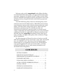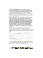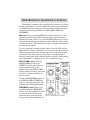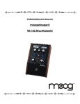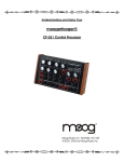
1
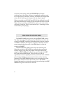
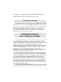
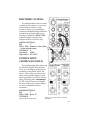
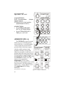
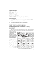
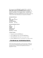
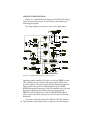
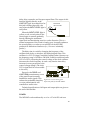
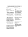
Understanding and Using Your
moogerfooger®
MF-104Z ANALOG DELAY
1
Welcome to the world of moogerfooger® Analog Effects Modules.
Your Model MF-104Z Analog Delay is a rugged, professional-quality
instrument, designed to be equally at home on stage or in the studio.
Its great sound and smooth player controls come from its state-of-theart analog circuitry, designed and built under Bob Moog's personal
direction.
Your MF-104ZAnalog Delay features an all-analog delay circuit
with delay times from 50 milliseconds to 1000 milliseconds. Its finely
tuned frequency response and overload contours produce the sound
quality of the best classic vintage delay devices. Each of the three
performance parameters may be controlled smoothly and
continuously by panel knob, expression pedal, or external control
voltage. Audio input and output signals may be set to any instrument
or line level. Housed in a rugged steel and hardwood enclosure, the
MF-104Z, like other moogerfooger instruments, has the classic good
looks, versatility, and high sound quality of the well-known vintage
MOOG synthesizers.
The following pages will first tell you how to hook up your MF104Z and set the panel controls for the ‘basic’ setup. Next, we'll explain
how your MF-104Z works. After that we'll go through the panel
features and give you suggestions on how to use your MF-104Z in
some specific applications. At the end of this booklet, you'll find
technical specifications, service, and warranty information, and
information about Moog Music.
CONTENTS
GETTING STARTED - - - - - - - - - - - - - - - - - - 3
WHAT IS AN ANALOG DELAY? - - - - - - - - - - - - 6
PERFORMANCE PARAMETER CONTROLS - - - - - - 7
THE WHITE SWITCHES - - - - - - - - - - - - - - - - - 8
THE AUDIO LEVEL CONTROLS - - - - - - - - - - - - 9
AUDIO OUTPUTS; EXPRESSION PEDALS - - - - - - - 11
TYPICAL SETUPS - - - - - - - - - - - - - - - - - - —- 12
TECHNICAL INFORMATION - - - - - - - - - - - - - 17
WARRANTY INFORMATION - - - - - - - - - - - - - 21
2
SPECIFICATIONS - - - - - - - - - - - - - - - - - - - 22
GETTING STARTED
Here are simple instructions on how you can quickly plug in and
try out your MF-104Z.
1. Unpack your MF-104Z. You can place it on a table or on a floor. We
suggest that you place it on a table while you become familiar with its
features.
2. Check that the power adapter has a nominal rating of +9 volts and
is also rated at your country's standard power voltage (120 volts A.C.
for the United States and Canada, 100 volts A.C. for Japan, and 220
volts A.C. for most other countries). Plug the power adapter's cord
into the MF-104SD's `+9V' jack. Then plug the power adapter itself
into a power voltage receptacle. (See Page 19 for more detailed
technical information on power adapters for the MF-104Z.)
3. Note that the BYPASS light is on. It will light up either red or
green. Red indicates that
the MF-104Z’s delay
circuit is off-line
(bypassed), while the
green indicates that the
delay circuit is on-line.
Pressing the `stomp
switch' will toggle the
BYPASS light between
red and green. For now,
leave the BYPASS light
on red.
Refer to Figure 1 for steps 4.
and 5.
4. Connect an instrument
cable from the MIX OUT Figure 1 - Basic connections: Instrument to
jack to a line-level input AUDIO IN, monitor amp to MIX OUT, and
power adapter to +9V.
on your amp or mixer.
3
Turn the volume control on your amp down but not off.
5. Connect an instrument cable from your signal source to the AUDIO
IN jack. You can feed virtually any instrument-level or line-level
signal through your MF-104Z. Examples are guitar, bass, keyboard,
theremin, drum machine, or Effects Send output on your mixer.
Refer to Figure 2 for step 6.
6. Set the MF-104Z panel controls as follows.
MIX
0
DELAY TIME
0.3
FEEDBACK
0
LOOP GAIN
0
DRIVE
fully
counterclockwise
OUTPUT LEVEL
fully
counterclockwise
Left Switch
SHORT
Right Switch
INT. LOOP
Play your instrument (or turn on
the signal source). Adjust the
volume control on your monitor
amp so that the sound level is
comfortable.
Now set the DRIVE and OUTPUT
Figure 2 - Basic settings for becoming
LEVEL controls exactly as
familiar with your MF-104Z.
described in steps 7. and 8.
7. Press the stomp switch so the
BYPASS light goes green. Playing your instrument, set the DRIVE
control so the INPUT LEVEL indicator lights up green-yellow or redyellow most of the time, and becomes bright red only on occasional
peaks.
8. Set the OUTPUT LEVEL control so that there is no loudness change
when the BYPASS light goes back and forth between green and red.
Once the DRIVE and OUTPUT LEVEL controls are set, you should not
change them unless you change the loudness of your signal source.
4
9. Switch the BYPASS light to green. Continuing to play your
instrument, turn the MIX control clockwise. When the MIX control is
at 0, you will hear just the direct (undelayed) signal. When the MIX
control is at 5 (midposition), you will hear both the direct and
delayed signal. When the MIX control is at 10, you will hear just the
delayed signal. Note that the delayed signal has a softer, more muted
quality than the direct signal, - just as natural echoes are softer and
more muted than direct sounds.
10. Set the MIX control to 5, so you hear both the direct and delayed
signals. Vary the setting of the DELAY TIME control. When the
control is fully counterclockwise, the delay is very short, - about 50
milliseconds. (A millisecond is a thousandth of a second.) When the
control is fully clockwise, the delay is about 500 milliseconds. Note
that when you turn the DELAY TIME control while you're playing,
the pitch will change briefly. This is because turning the DELAY
TIME control causes your sound to stretch or compress as it goes
through the delay circuit, thereby speeding up or slowing down the
vibrations.
11. Set the left switch to LONG. This doubles the delay time. It also
imparts an even more muted quality to the delayed signal.
Experiment with various settings of the DELAY TIME control and the
SHORT-LONG switch to get a feeling for how they affect the delayed
signal.
12. Return the left switch to SHORT and the DELAY TIME control to
midposition. Turn the FEEDBACK control slowly clockwise. You will
now hear a series of echoes of each sound that you play. The
FEEDBACK control creates the series of echoes by mixing a portion
of the delayed signal with the signal from your instrument. When the
FEEDBACK control is set to about 8, the echoes sustain indefinitely.
With the FEEDBACK control above 8, the echoes build up chaotically
into some amazing electronic textures.
In the next sections we'll explain how an analog delay works and
look at your MF-104Z in more detail. For now, get a feel for your MF104Z's controls by experimenting with different settings.
5
WHAT IS AN ANALOG DELAY?
A delay circuit produces a replica of an audio signal a short time after
the original signal is received. If you listen to the original (direct)
signal and the delayed signal together, the delayed signal will sound
like an echo of the direct. To make a whole series of echoes that die
out gradually, you feed the delayed output signal back to the input.
You can determine how far apart the echoes are by adjusting the
delay time of the delay circuit, and you can adjust how fast the
echoes die out by adjusting the amount of feedback from the delay
circuit output to its input. In addition, you can determine how loud
the echoes are by adjusting the mix between the direct signal and the
delayed signal.
Today there are three types of delay devices: tape, analog, and
digital. The first delay devices used magnetic tape to create the delay.
The sound was recorded on a moving tape, and then played back
after the tape had moved a few inches or so. Then, during the early
`70's, large-scale semiconductor analog delay circuits became
available. These were called bucket brigade delay chips, because they
functioned by passing the audio waveform down a chain of several
thousand circuit cells, in analogy to water being passed by a bucket
brigade to put out a fire. Each cell in the chip introduces a tiny delay.
The total time delay depends on the number of cells and on how fast
the waveform is `clocked', or moved from one cell to the next. Analog
delays were less noisy, easier to use, and more reliable than tape echo
units, and came to be more widely used.
More recently, digital delay units have come into use. In a digital
delay unit, the sound signal is first converted to numbers. The
numbers are stored in a digital memory for a certain time, and then
retrieved and reconstructed into the delayed audio waveform. One
significant difference between analog and digital delay units is that
the particular frequency and overload contours of well-designed
analog devices generally provide smoother, more natural series of
echoes than digital delay units. Another difference is that the echoes
of a digital delay are static because they are the same sound repeated
over and over, whereas a bucket brigade device itself imparts a
warm, organically evolving timbre to the echoes.
The design of your MF-104Z Analog Delay is unique because it
combines authentic, finely-tuned vintage analog bucket-brigade
delay circuitry with analog-synthesizer-style voltage control of delay
time, feedback, and direct/delay mix.
6
PERFORMANCE PARAMETER CONTROLS
Performance parameters are controls that are meant to be played
during performance. Each of the MF-104Z's performance parameters
is controlled both by a front panel knob and by a pedal/control jack
on the rear panel. The parameters are MIX, DELAY TIME, and
FEEDBACK..
MIX control: As you turn the MIX knob clockwise from 0 to 5, the
delayed signal becomes louder while the direct signal remains at
maximum volume. Then, as you turn the MIX knob from 5 to 10, the
delayed signal remains at maximum volume while the direct signal
decreases to silence. This characteristic gives a natural-sounding mix
for most music signals.
If you're applying a sustained steady pitch to the MF-104Z and the
MIX control is set near midposition, you may find that the direct and
delayed signals alternately reinforce and cancel each other in rapid
succession as the delay time is varied. This is a normal result of
mixing a steady pitch with a delayed replica of itself. It is the analogdelay equivalent of `standing waves' in a reverberant room.
DELAY TIME control: With the
SHORT/LONG switch set on
SHORT, the delay time will vary
from 50 milliseconds to 500
milliseconds as the DELAY TIME
knob is turned clockwise. Note that
the knob is calibrated directly in
time (seconds).
With the SHORT/LONG switch set
on LONG, the DELAY TIME knob
will vary the delay time from 100
milliseconds to 1000 milliseconds.
FEEDBACK control: There is no
feedback when the FEEDBACK
knob is on 0. The feedback increases
as you turn the knob clockwise.
When the knob is around 8, the
Figure 3 - MF-104Z Front Panel.
echoes will sustain indefinitely for
7
most delay time settings. With the FEEDBACK knob turned
clockwise past 8, the echoes will grow in amplitude until they reach
the overload point of the delay circuitry. In addition, the background
noise will also build up and compete with the delayed signal.
When you switch your MF-104Z into BYPASS, the feedback loop will
shut down and the echo stream will die out within less than a second.
Then, when you switch your MF-104Z on again, a new echo stream
will begin to build up. This is a convenient way of `canceling' an echo
stream while you're playing.
THE WHITE SWITCHES
The SHORT-LONG switch works with the DELAY TIME control.
The delay time range is 50 milliseconds to 500milliseconds when the
switch is on SHORT, and 100 to 1000 milliseconds when the switch is
on LONG. In addition, the frequency response of the delay circuit is
more restricted when the switch is on LONG than it is when the
switch is on SHORT.
The INT.LOOP-EXT.LOOP switch selects the feedback path.
When this switch is in INT.LOOP, the feedback path goes directly
from the output of the delay circuit back to the input. When this
switch is in EXT.LOOP, the feedback loop goes through the LOOP
OUT jack and the LOOP IN jack. This provides you with an
opportunity to insert a signal processor of your choice in the feedback
path, thereby enabling you to process the echoes as they're being
generated. The LOOP GAIN knob affects only the external loop, and
has no effect whatsoever when the switch is set on INT.LOOP.
Detailed information on using the external loop and setting the LOOP
GAIN knob is given in the next two sections.
8
THE AUDIO LEVEL CONTROLS
The DRIVE control adjusts the signal level at the delay circuit
input. With this control you can set the right input level for virtually
any instrument or line-level signal source. Turn this control
counterclockwise for strong signal inputs, and clockwise for weaker
sound sources.
The INPUT LEVEL light tells how strong the input signal is after
being adjusted by the DRIVE control. As the signal level increases, the
light goes from dark, to pale green, to bright green, to yellow-green, to
yellow-red, to bright red. When the light is green, the signal is below
the level that results in audible distortion. When the light is yellow,
some low order distortion may be audible, giving the sound a warm
analog quality. When the signal is strong enough to drive the light
into the red, the distortion at the output becomes more distinctly
audible.
There are two factors which you should keep in mind when
adjusting the DRIVE control.
1.The bypass signal is a faithful replica of your instrument signal, but
is buffered by the audio input circuit. As a result, if the DRIVE control
is turned up to where the INPUT LEVEL light stays red when you
play, the bypass signal may be audibly distorted. You can avoid
distortion of the bypass signal by adjusting the DRIVE control so that
the INPUT LEVEL indicator generally stays in the green and yellow
region, and goes red only on the loudest peaks.
2. The DRIVE control should be set while the BYPASS indicator is
green. When you switch the BYPASS indicator from green to red, you
may see the INPUT LEVEL indicator change color slightly. This is a
normal feature of the MF-104Z audio input circuitry.
Once you set the DRIVE control as described above, the input level
is optimized for best operation of your MF-104Z's circuitry. Do not
change the DRIVE setting except to tweak the input level or to
compensate for changes in the level of your instrument signal.
The OUTPUT LEVEL control adjusts the levels of the direct and
delayed signals that appear at the MIX OUT and DELAY OUT jacks.
This control does not affect the level of the bypassed signal, and it
does not affect the level of the signal that appears at the LOOP OUT
9
jack. You should adjust the OUTPUT LEVEL after you set the DRIVE
control. Set the OUTPUT LEVEL control so that you get the desired
balance between on-line and bypass signals when you toggle the
stomp switch.
The LOOP GAIN control adjusts the signal level which is applied
to the LOOP IN jack. You use this control to set the right loop gain for
the external sound processing device that you connect between the
LOOP OUT jack and the LOOP IN jack. Connect the external sound
processor and set the LOOP GAIN control as follows:
1. Use patch cords to connect a) the MF-104Z LOOP OUT jack to the
Audio In (instrument) jack on your processor, and b) the Audio Out
(amplifier) jack on your processor to the MF-104Z LOOP IN jack.
2. Turn the external processor on. Playing your instrument, set your
processor's Drive or Input Level control for proper operation of the
processor.
3. Set your processor's Output Level control (if it has one) to balance
your processor's bypass signal with its on-line signal.
4. Finally, set your MF-104Z's LOOP GAIN control so the LOOP
LEVEL light is green-yellow or yellow-red most of the time that you
are playing, and flashes red only
briefly on loudness peaks.
An alternate way of setting
up the gain of the external feedback
loop is a) to temporarily connect
your external processor's output
directly to your amplifier instead of
to the MF-104Z's LOOP IN jack,
then b) perform steps 2. and 3. as
written above, c) connect your
Figure 4 - The MF-104Z’s jack panel. external processor's output to the
MF-104Z’s LOOP IN jack and d)
perform step 4. This may be somewhat easier for some types of
processing devices.
Note again that the LOOP GAIN control and the LOOP LEVEL
light have no effect when the feedback mode switch is on INT.LOOP.
10
An example of a setup using the MF-104Z's EXT.LOOP mode is
"NEPTUNE'S CANYON", which is given on page 15.
AUDIO OUTPUTS
Your MF-104Z has two audio output jacks: DELAY OUT and MIX
OUT. When the unit is on-line, the DELAY OUT jack delivers just the
signal that actually goes through the delay circuit, and the MIX OUT
jack delivers both direct and delayed signals in the proportion
determined by the MIX control. When the unit is in bypass mode,
both jacks deliver just the bypass signal.
EXPRESSION PEDALS
AND VOLTAGE CONTROL
You now know what each of the control knobs does to the sound
of the MF-104Z. Each of the three performance parameters, MIX,
TIME, and FEEDBACK, has an expression pedal/control input which
duplicates its effect. This enables you to plug in up to three
expression pedals to play the MF-104Z with your feet as well as your
hands. The moogerfooger EP-1 Expression Pedal is designed for this
purpose or you can use expression pedals with equivalent
specifications. See the Technical Information section on Page 19 for
more information on pedal specifications.
When you plug an expression pedal into one of the pedal inputs
on your MF-104Z, the pedal adds to the effect of the corresponding
control. For example, let's say that you plug an expression pedal into
your MF-104Z's MIX input. With the pedal all the way back, the
direct-delay mix is set by the MIX knob. Then, as you advance the
pedal, the delay signal increases, just as if you turned the MIX knob
up. A good rule to follow is: when you use the expression pedal, set
the corresponding knob for the lowest value you want. Advancing
the pedal increases that value.
The MIX, TIME, and FEEDBACK jacks can also be used as control
signal inputs. This enables you to use your MF-104Z with virtually
11
any control signal source: modular analog synthesizers, MIDI-to-CV
converters, etc. You will find examples of interfacing your MF-104Z
with external control signals on Pages 19-20, and you will find
technical information on Pages 17-18.
TYPICAL SETUPS
Here are a few interesting setups for your to experiment with. Try
changing the knobs with your hands. Then plug in one or more
expression pedals and try the same things with your feet.
SLAPBACK
A short delay time and no feedback produce a good slapback
effect.
INITIAL SETTINGS:
MIX
5
DELAY TIME Full Counter Clockwise
FEEDBACK 0
Left SwitchSHORT
Right Switch INT.LOOP
"DUB" ANALOG DELAY EFFECT
Lengthen the delay time just a little, add some feedback, and
you're set up to produce your own DUB remix. Ride the FEEDBACK
knob (or plug an expression pedal into the FEEDBACK jack) to
control the echoes.
INITIAL SETTINGS:
MIX
5
DELAY TIME between 0.25 and 0.3
FEEDBACK between 7 and 9
Left SwitchSHORT
Right Switch INT.LOOP
12
RHYTHMIC ECHOES
By setting the delay time to exactly
one beat of your music, or to an exact
whole number of beats or exact
fraction of a beat, you can build up
expressive rhythmic backgrounds that
are made up of phrases that you've
just played. Adjust the DELAY TIME
control carefully to get the exact
tempo at which you want to play.
INITIAL SETTINGS:
MIX
5
DELAY TIME between 0.4 and .8(Set
for the desired tempo.)
FEEDBACK 6
Left Switch
LONG
Right Switch INT.LOOP
ECHOES WITH
CHORUS (FIGURE 5)
By modulating the delay time with
an externally applied slow random
wave, you can impart small random
variations to the pitches and to the
echoes. Then, when you listen to the
direct sound and the delayed sound
(echoes) together, you'll hear a chorus
effect. This setup uses a moogerfooger
CP-251 Control Processor to supply
the slow random wave and to adjust
the wave's amplitude with an
attenuator.
MF-104Z SETTINGS:
MIX
5
DELAY TIME about .15
FEEDBACK 7
(Setup continues on next page.)
Figure 5 - Setup for ECHOES WITH
CHORUS.
13
Left SwitchSHORT
Right Switch INT.LOOP
CP-251 SETTINGS:
RATE 9 o'clock position
(Adjusts
speed of chorus.)
ATTENUATOR 9 o'clock position
(Adjusts depth of chorus.)
CONNECTIONS:
•
From SAMPLE-AND-HOLD
OUT 2 to ATTENUATOR IN
•
From ATTENUATOR OUT to
TIME jack on MF-104Z
AIRSHOW (FIG. 6)
The FEEDBACK control is turned
all the way up, so the background
noise builds up to a constant rumble.
A slow square wave from an LFO
provides audio clicks that compete
with the rumble, giving it some
rhythmic structure. You can find
almost any propeller sound known to
modern man, plus some never-before
heard sounds, by experimenting with
the LFO RATE, the DELAY TIME, and
the FEEDBACK controls. The LFO
square wave comes from a
moogerfooger® CP-251 control
processor in this example, but it could
come from any LFO that produces a
square wave, - such as the LFO OUT
of a moogerfooger MF-102 Ring
Modulator.
(setup continues on next page)
14
Figure 6 - Setup for AIRSHOW.
INITIAL SETTINGS:
MIX
10
DELAY TIME 0.1 to 0.3
FEEDBACK 9 to10
Left Switch SHORT
Right Switch INT.LOOP
CP-251 LFO RATE 9 o'clock position (about 0.5 Hz)
CONNECTIONS:
•
From CP-251 LFO square wave output jack, to MF-104Z AUDIO
IN jack.
•
From MF-104Z MIX OUT jack, to your amplifier.
NEPTUNE'S CANYON (RING
MODULATOR IN EXTERNAL LOOP;
FIGURE 7)
This setup shows how the external loop is used. The external loop
works best with processors that do not change the amplitude of the
signal, - such as a
ring modulator. By
placing a ring
modulator or pitch
shifter in the external
loop, you can create
echo streams that
change in pitch and
timbre as they evolve.
This setup uses a
moogerfooger MF-102
Ring Modulator in
the external feedback
loop. The echo
spacing is determined
by the MF-104Z TIME
control and SHORTFigure 7 - Setup for NEPTUNE’s CANYON
15
LONG switch, the echo density is determined by the FEEDBACK
control, and the tuning of the echoes is determined by the MF-102
FREQUENCY control and LO-HI switch. You'll also hear interesting
changes when you vary the MF-102 MIX, AMOUNT, and RATE
controls, and the waveform switch.
MF-104Z SETTINGS:
MIX
10
DELAY TIME 0.2 to 0.3
FEEDBACK 6 to 8 (Depends on exact setting of the LOOP GAIN control.)
Left Switch SHORT
Right Switch EXT.LOOP
MF-102 RING MODULATOR SETTINGS:
RATE
0.2 to 0.4
AMOUNT
5
MIX
10
FREQUENCY 240
Left Switch sine
Right Switch HI
CONNECTIONS:
•
From MF-104Z LOOP OUT jack to MF-102 AUDIO IN jack.
•
From MF-102 AUDIO OUT jack to MF-104Z LOOP IN jack.
•
Sound source is plugged in to the MF-104Z AUDIO IN jack
•
Amplifier is plugged in
to the MF-104Z MIX OUT
jack.
SWIRLING
ECHOES
(PHASER AND
ANALOG DELAY;
FIGURE 8)
Figure 8 - Setup for Swirling Echoes
16
This setup uses both AUDIO OUT and AUX. OUT of an MF-103
Phaser. When the phaser's RESONANCE control is turned up, the
AUDIO OUT is highly colored but the AUX. OUT is not. The
instrument signal goes first through the phaser. The AUX OUT goes
directly to one input on your amplifier or mixer, while the main
AUDIO OUT goes through the MF-104Z. Thus, the direct sound is not
colored, but the echoes swirl because of the phaser modulation.
MF-104Z SETTINGS:
MIX
10
DELAY TIME 0.2 to 0.3
FEEDBACK 7
Left Switch SHORT
Right Switch
INT.LOOP
MF-103 PHASER SETTINGS:
RATE
2
AMOUNT
7
SWEEP
4
RESONANCE 8
Left SwitchHI
Right Switch 12-STAGE
CONNECTIONS:
•
Instrument to MF-103 AUDIO IN jack.
•
MF-103 AUDIO OUT jack to MF-104Z AUDIO IN jack.
•
MF-103 AUX. OUT to first input on your amp or mixer
•
MF-104Z AUDIO OUT jack to second input on our amp or mixer
TECHNICAL INFORMATION
NOTE: The following information on the next page is intended for
use by people who understand analog circuitry and have enough
practical experience to interconnect sophisticated electronic
equipment correctly.
17
CIRCUIT CONFIGURATION:
Figure 9 is a simplified block diagram of the MF-104Z Analog
Delay. Some unique features of the circuit are described in the
following paragraphs.
The input signal goes directly to a low -noise, high-input-
Figure 9 - Simplified Block Diagram of the MF-104Z
impedance buffer amplifier. The gain is set by the DRIVE control.
This amplifier has two outputs: the bypass signal (which is an
accurate replica of the input signal), and the signal that feeds the
delay circuit. If the gain is too high (indicated by the INPUT
LEVEL light going frequently to red), this amplifier may clip, and
the bypass signal may be audibly distorted. In general, the
DRIVE control should be set so that the INPUT LEVEL light is
yellow most of the time, and goes into the red only occasionally
and briefly.
The heart of the audio path is the DELAY CIRCUIT function.
18 This includes lowpass input filters, compressor, bucket-brigade
delay chips, expander, and lowpass output filters. The output of this
function appears directly at the
LOOP OUT jack. Its nominal level at
This must be
+9V to +15V DC.
this jack is 0 dBm (about 0.8 volts
rms) when the INPUT LEVEL light is
red-yellow.
When the INPUT LEVEL light is
yellow or red, several points in the
circuit begin to saturate gradually,
thereby limiting the maximum
signal level and introducing some low -order distortion. This is a
normal component of the sound of analog gear. It actually enhances
the sound quality over what you would have if the MF-104Z
produced no distortion whatsoever (i.e., if it were `technically
perfect')
The delay time is varied by changing the frequency of the
oscillator that clocks, or advances, the bucket brigade chips. This
oscillator is a VCO (Voltage Controlled Oscillator) that operates over
the frequency range of 10 kHz to 200 kHz. Unlike conventional audio
VCO's or LFO's, increasing the control voltage of the clock oscillator
decreases the clock's frequency in such a way that the time delay
increases in exact proportion to the
control voltage change. (The clock
VCO's signal itself is not accessible
to the user.)
Except for the DRIVE and
LOOP GAIN potentiometers, none
of the panel controls actually
handles the audio signals. This
Figure 10 - Correct wiring of an
reduces the probability that dirty expression pedal for the MF-104SD.
or worn potentiometers will
contribute to audio noise.
Technical specifications of all input and output jacks are given at
the end of this booklet.
POWER:
The MF-104Z works satisfactorily on +9 to +15 volts DC and uses
19
about 300 milliamperes of
current. You can power your MF104Z from virtually any power
adapter which has a nominal
rating of between +9V and +12V
at a rated current of at least 300
Figure 11 - Correct wiring of a tip-ring - milliamperes, and has the
sleeve plug for connecting a pedal
appropriate power connector.
control input to a source of external
control voltage.
If you ever use a power
source other than that supplied
with your MF-104Z, be sure that
the voltage never exceeds +15 volts. Power sources with voltages in
excess of +15 volts may cause serious damage to the MF-104Z's
circuit.
PEDAL/CONTROL JACKS:
All three pedal/control jacks are 1/4" tip-ring-sleeve (stereo)
phone jacks. The sleeves are grounded and the ring terminals are
supplied with +5.0 volts which is current-limited to about 0.5
milliamperes. The tip terminals receive the variable voltages from the
pedals.
An expression pedal for use with the MF-104Z should contain a
50K ohm or 100K ohm potentiometer which is connected from the
sleeve to the ring terminals. The potentiometer wiper is connected to
the tip terminal. The pedal cable should be shielded with the shield
connected to the sleeve terminal. See Figure 10.
When connecting one or more pedal/control jacks to a source of
external control voltage such as an analog synth or a MIDI-to-CV
converter, you should use patch cords with tip-ring-sleeve phone
plugs. The ring terminal should not be connected to anything, so that
the MF-104Z's source of +5.0 volts is not shorted out. Or, if you do
not plan to use any expression pedals with your MF-104Z but would
like to apply external control voltages to one or more pedal/control
inputs, you can use patch cords with regular two-conductor phone
plugs. These will short out the +5.0 volt supply to the ring contacts.
This voltage is current limited, so you won't burn anything out, - but
20
no pedal will work in any of the pedal control jacks if a tip-sleeve
plug is plugged into even one of the pedal jacks.
Applying a varying voltage to the tip terminal of a pedal/control
jack has the same effect as turning the corresponding knob. A voltage
of +5 volts at the tip terminal is equivalent to turning the knob
through its entire range. You can program your MF-104Z's
performance parameters entirely from external control voltages by
turning all three performance parameter knobs (but not the DRIVE,
OUTPUT LEVEL, or LOOP GAIN knobs) counterclockwise, and
feeding 0 to +5V programming voltages to the tips of the pedal/
control jacks.
LIMITED WARRANTY
Moog Music warrants that its products will be free from defects
in materials and workmanship, and shall conform to specifications
that were current at the time of shipment, for a period of one year
from date of purchase. During the one-year period, any defective
products will be repaired or replaced, at Moog Music’s option, on a
return-to-factory basis. This Warranty covers defects that Moog
Music determines are no fault to the user.
RETURNING YOUR MF-104Z FOR REPLACEMENT/REPAIR
You must obtain prior approval and an RMA number from Moog
Music before returning any product to us. (Call 828-251-0090 or email
[email protected] to obtain approval.) Wrap your MF104Z carefully and pack it with the power adapter in its original
carton. The warranty will not be honored if the product is not
properly packed. Then send it to Moog Music (UPS is recommended)
with transportation and insurance charges paid.A reasonable cost for
service and for materials and return freight will be changed to replace
materials defective through the fault of the user, or for which the one
year warranty period has expired.
Transportation and insurance charges from Moog Music to your
United States address, of products repaired or replaced under
warranty, will be paid by Moog Music.
21
MF-104Z SPECIFICATIONS
DESCRIPTION:
JACK PANEL FEATURES:
Analog effects module incorporating bucket brigade • AUDIO IN 1/4” phone jack - accepts any
analog delay circuit with voltage-controlled delay
instrument- level or line-level signal from -16
time, feedback, and direct-delayed signal mix.
dBm to +4 dBm. Input impedance is one
megohm.
FRONT PANEL FEATURES:
• DELAY OUT 1/4” phone jack - Nominal output
• MIX rotary control - sets the proportion of direct to
level from -16 dBm to +4 dBm, depending on
delayed signal that appears at the MIX output
setting of OUTPUT LEVEL control. Delayed
jack.
signal only. Output impedance is 5,000 ohms.
• DELAY TIME rotary control - determines the
• MIX OUT 1/4” phone jack - Nominal output
delay time. Range is 50-500 milliseconds when
level of -16 dBm to +4 dBm, depending on
SHORT-LONG switch is in the SHORT position,
setting of the OUTPUT LEVEL control. Mix of
and 100-1000 milliseconds when the switch is in
delayed and direct signals. Output impedance
the LONG position.
is 5,000 ohms.
• FEEDBACK rotary control - determines the
• MIX, TIME, FEEDBACK, all of which are
amount of the delayed signal that is fed back to
stereo 1/4” jacks that accept moogerfooger
the delay circuit input. When this control is fully
EP1 (or equivalent) expression pedals, or
counterclockwise, there is no feedback; when
control voltages from two-circuit or three-circuit
the control is fully clockwise, there is enough
1/4” jacks.
feedback to place the delay circuit into self• LOOP OUT 1/4” phone jack - 0 dBm nominal
oscillation.
output level, delayed signal only. Output
• DRIVE rotary control - adjusts the gain of the
impedance is 1,000 ohms.
audio input circuit.
• LOOP IN 1/4” phone jack - -8 dBm to +4 dBm
• OUTPUT LEVEL rotary control - balances the
nominal input amplitude range. Input
direct/delayed signals with the bypassed signal.
impedance is 1 megohm.
• LOOP GAIN rotary control - adjusts the gain of
the circuit following the LOOP IN jack.
GENERAL SPECIFICATIONS:
• SHORT-LONG switch - chooses between the
• CASE: Black steel panel with hardwood sides
short and long Delay Time ranges.
- classic analog appearance.
• INT.LOOP - EXT.LOOP switch - Determines
• DIMENSIONS: 9” x 6” x 2-1/2”
whether the feedback signal will be routed
• Net Weight: 2 lb
directly from the delay circuit output back to its
• SHIPPING WEIGHT: 4 lb, including
input, or through the LOOP OUT and LOOP IN
instruction manual and +9 Volt, 300milliamjacks and an external processor.
pere power adapter.
• INPUT LEVEL - a tri- color LED used to set the • LINE POWER REQUIREMENTS: 120 volt,
DRIVE control.
5W. 220 volt power adapter available on
• LOOP LEVEL - a tri- color LED used to set the
special order
LOOP GAIN control.
• BYPASS - a two-color LED used to tell whether
the unit is on-line or bypassed.
• ON/BYPASSS - a rugged, smooth-acting ‘stomp
switch’.
22
Notes
23
MOOG MUSIC, Inc.
554C RIVERSIDE DRIVE
ASHEVILLE, NC 28801
Phone (828) 251 0090
FAX (828) 254 6233
EMAIL: [email protected] or [email protected]
WEB SITE: http://www.moogmusic.com
Entire contents © 2005 by Moog Music, Inc.
2424
Printed July 2005