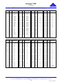
1
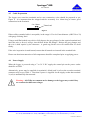
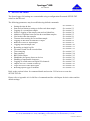
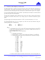
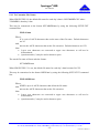
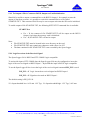
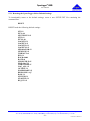
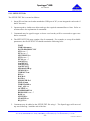
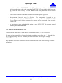
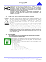
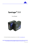
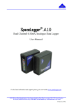
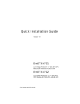
SpaceLogger .S10 ® User Manual For the latest information and support please go to our website www.spacelogger.com ©2012-13 Richard Paul Russell Limited, New Harbour Building, Bath Road, Lymington SO41 3SE United Kingdom Tel +44 (0) 1590 679755 Fax +44 (0) 1590 688577 e-mail [email protected] web www.r-p-r.co.uk 017SL167/3 04/09/13 SpaceLogger®.S10 User Manual 1 INTRODUCTION ....................................................................................................................................................................... 2 2 QUICK START: EASY STEPS TO DATA LOGGING ............................................................................................................... 3 3 EXAMPLE APPLICATION ......................................................................................................................................................... 3 4 CONNECTING ........................................................................................................................................................................... 4 4.1 4.2 4.3 4.4 4.5 4.6 5 5.1 5.2 5.3 5.4 5.5 5.6 5.7 5.8 5.9 5.10 5.11 5.12 5.13 5.14 5.15 5.16 5.17 5.18 5.19 5.20 5.21 5.22 5.23 6 6.1 6.2 7 Terminal Strip Arrangement ................................................................................................................................................. 4 Generic Terminal Allocations ............................................................................................................................................... 4 RS232 Interface .................................................................................................................................................................... 5 Switch inputs ........................................................................................................................................................................ 5 Cable Preparation.................................................................................................................................................................. 6 Power Supply........................................................................................................................................................................ 6 SETUP FEATURES ................................................................................................................................................................... 7 Setting the time & date ......................................................................................................................................................... 8 To Define the Data Sample(s) to be Recorded ...................................................................................................................... 9 To Enable Recording of Second Data Sample .................................................................................................................... 10 To Select whether the STX and ETX Identifiers are Logged.............................................................................................. 11 To Add Separator between First & Second Data Samples .................................................................................................. 11 To Add a Line Break after Each Data Set ........................................................................................................................... 12 To Set a Timeout ................................................................................................................................................................ 12 To Enable Logging from the Second RS232 Input ............................................................................................................. 13 To Set the Baud Rate .......................................................................................................................................................... 13 To Select a Logging Interval............................................................................................................................................... 14 To Record Data to a Single Log File .................................................................................................................................. 14 To Customise File Names ................................................................................................................................................... 15 To Disable the Time-Stamp ................................................................................................................................................ 16 To Record all Data (Disable Sampling) .............................................................................................................................. 16 To Output RS232 Data from the SpaceLogger.S10 ............................................................................................................ 17 To Enable a Handshake Response ...................................................................................................................................... 17 To Record Unprintable ASCII Characters .......................................................................................................................... 19 To Record the Status of the Digital Input Channels ............................................................................................................ 19 To Output a File’s Content to RS232 Output on Card Initialisation ................................................................................... 20 Logic Inversion of the Received Signal .............................................................................................................................. 20 Resetting the SpaceLogger.S10 to Default Settings............................................................................................................ 21 SETUP.TXT file ................................................................................................................................................................. 22 Notes on saving file SETUP.TXT ...................................................................................................................................... 23 LOGGING................................................................................................................................................................................. 24 SD Card .............................................................................................................................................................................. 24 Data Transfer ...................................................................................................................................................................... 25 SPACELOGGER.S10 SPECIFICATION .................................................................................................................................. 26 APPENDICES ..................................................................................................................................................................................... 28 A1 A2 A3 A4 A5 A6 SETUP.TXT Commands .................................................................................................................................................... 28 ASCII – American Standard Code for Information Interchange ......................................................................................... 30 Guarantee ............................................................................................................................................................................ 31 Electromagnetic Conformity ............................................................................................................................................... 32 WEEE (Waste, Electrical and Electronic Equipment) Statement ....................................................................................... 33 RoHS Statement ................................................................................................................................................................. 33 ©2012-13 Richard Paul Russell Limited, New Harbour Building, Bath Road, Lymington SO41 3SE United Kingdom Tel +44 (0) 1590 679755 Fax +44 (0) 1590 688577 e-mail [email protected] web www.r-p-r.co.uk -1017SL167/3 04/09/13 SpaceLogger®.S10 User Manual 1 INTRODUCTION The SpaceLogger®.S10 is designed as a stand-alone data logger for serial data logging from a wide range of devices and sensors with RS232 output. SpaceLogger.S10 records samples of data from up to two RS232 data sources. Each data record is date & time-stamped. A new file (default format is .CSV) is generated for each day’s worth of data. Data is stored onto an SD card. SD cards with up to 2 GByte capacity are compatible with SpaceLogger. Higher capacity cards are not compatible. SpaceLogger will also accept other compatible data storage cards, such as MMC and MMC mobile. The SD card can be removed from the logger and inserted into a card reader connected to a PC. Stored data files are accessed in the same way as files on the computer's other disk drives. The text files may be read and manipulated in any standard Office applications (e.g. Notepad or MS Excel). The SpaceLogger.S10 will also output RS232 data to another device. Refer to section 5.15 for details. The logger requires a 7 - 30 volt DC supply which can be provided by an AC/DC mains adaptor or suitable battery. Document revision summary Issue 1 2 Date Feb 2012 Aug 2013 3 Sept 2013 Description Original document Firmware version 2v2h. Second RS232 input implemented. Second data sample added. Single log file option added. Handshake with response function added. Improved definitions for STX and ETX including extended strings and logging controls. Logic inversion of RS232 input enabled. Firmware version 2v2j. Timeout LED indication added. Option to include comma separator between 2 RS232 samples added. Our products are in continuous development and therefore specifications may be subject to change and design improvements may be implemented without prior notice. Please visit our web site www.r-p-r.co.uk for the most up to date information on our products. ©2012-13 Richard Paul Russell Limited, New Harbour Building, Bath Road, Lymington SO41 3SE United Kingdom Tel +44 (0) 1590 679755 Fax +44 (0) 1590 688577 e-mail [email protected] web www.r-p-r.co.uk -2017SL167/3 04/09/13 SpaceLogger®.S10 User Manual 2 QUICK START: EASY STEPS TO DATA LOGGING ……. ……. ……. ……. ……. ……. ……. ……. ……. Connect RS232 inputs Set up logging preferences with SETUP.TXT file Power on Set time and date Insert SD card Start recording data see section 4 see section 5 see section 4.6 see section 5.1 see section 6.1 see section 6.2 Stop recording data (press purge button) Remove card and transfer to PC to view and analyse data see section 6.2 see section 6.2 3 EXAMPLE APPLICATION Sensor 1 Switch (optional) SD card RS232 data Sensor 2 Manual transfer of SD card to PC card reader RS232 data SpaceLogger.S10 Figure 1 ©2012-13 Richard Paul Russell Limited, New Harbour Building, Bath Road, Lymington SO41 3SE United Kingdom Tel +44 (0) 1590 679755 Fax +44 (0) 1590 688577 e-mail [email protected] web www.r-p-r.co.uk -3017SL167/3 04/09/13 SpaceLogger®.S10 User Manual 4 CONNECTING 4.1 Terminal Strip Arrangement POWER 1 2 3 4 5 6 7 8 9 10 11 12 13 14 15 16 Figure 2 4.2 Generic Terminal Allocations SpaceLogger Terminal 1 2 3 4 5 6 7 8 9 10 11 12 Signal description Use Power GND Supply +V (+7 to 30V dc) GND N/A GND N/A Switch GND 1 Switch input 1 Switch GND 2 Switch input 2 GND RS232 output 2 13 RS232 input 2 14 RS232 output 1 15 16 RS232 input 1 RS232 GND 1 Power RS232 signal input/output ground Reserved for future options RS232 signal input/output ground Reserved for future options Switch to ground (see section 5.18) Switch to ground (see section 5.18) RS232 signal input/output ground Secondary RS232 signal output (see section 5.16) Secondary RS232 signal input (see section 5.6) RS232 signal output (see section 5.15) Primary RS232 signal input from device/sensor Table 1 ©2012-13 Richard Paul Russell Limited, New Harbour Building, Bath Road, Lymington SO41 3SE United Kingdom Tel +44 (0) 1590 679755 Fax +44 (0) 1590 688577 e-mail [email protected] web www.r-p-r.co.uk -4017SL167/3 04/09/13 SpaceLogger®.S10 User Manual 4.3 RS232 Interface Connection to the RS232 serial data source(s) should be made as per Table 1. This table should be read in conjunction with Figure 2. Wires should be prepared as per section 4.5. When just one RS232 source is connected, the Primary RS232 input 1 should be used. The Secondary RS232 input 2 is limited to 4800 baud rate. secondary input via the RX2 command are given in section 5.6. 4.4 Details on how to enable the Switch inputs The status of two switches connected between terminals 7 and 8 and terminals 9 and 10 can be added to the logged data. Details of how this is activated are given in the SWITCH command section 5.18. Figure 3 shows the input circuit for one of the switch inputs. 3V PROCESSOR R2 R1 R3 C1 SWITCH GND SpaceLogger.S10 Figure 3 Note if it is required to drive a switch input directly from the user’s circuit the input signal must not exceed 3 volts. ©2012-13 Richard Paul Russell Limited, New Harbour Building, Bath Road, Lymington SO41 3SE United Kingdom Tel +44 (0) 1590 679755 Fax +44 (0) 1590 688577 e-mail [email protected] web www.r-p-r.co.uk -5017SL167/3 04/09/13 SpaceLogger®.S10 User Manual 4.5 Cable Preparation The logger uses screwless terminals and to ease connection, wires should be prepared as per Figure 4. It is important that the stripped ends be accurately 9 to 10mm long to ensure good connections in the terminals. 9 to 10mm Tinned end Figure 4 Either solid or stranded cable is acceptable, in the range 0.32 to 0.65 mm diameter (AWG 28 to 22) with gauge 24 being ideal. Using a small flat headed screw-driver fully depress the grey plunger for the required terminal and insert the wire as far as it will go, into the hole below the plunger. Release the grey plunger and the wire is held captive by the connector. A gentle tug on the wire will confirm that it is held firmly. If the wire in question is multi-strand, ensure that all strands are inserted in the terminal hole. Please note that interconnection of all components should be completed prior to applying power. 4.6 Power Supply When the logger is powered using a 7 to 30 V DC supply the central pin on the power socket should be to GND. Alternatively, power may be supplied via terminals 1 (black) and 2 (red) on the screwless terminal connector strip, as per Table 1. Note that if power is supplied via the supply socket then terminal 2 (red) is automatically disconnected. Warning: All GNDs are common and so damage to the logger may result if they are connected to different voltages. ©2012-13 Richard Paul Russell Limited, New Harbour Building, Bath Road, Lymington SO41 3SE United Kingdom Tel +44 (0) 1590 679755 Fax +44 (0) 1590 688577 e-mail [email protected] web www.r-p-r.co.uk -6017SL167/3 04/09/13 SpaceLogger®.S10 User Manual 5 SETUP FEATURES The SpaceLogger.S10 settings are customisable using a configuration file named SETUP.TXT written to the SD card. The following parameters may be modified using defined commands: Setting the time & date Start and end character strings to define each data sample Logging of a second data sample Selective logging of the sample start and end identifiers Addition of separator between first & second data samples Line breaks after data samples Timeout when waiting for second data sample Logging of data from second RS232 input Baud rate of RS232 input/output Logging interval/sample rate Recording to single log file File name format for the recorded data Time-stamping Data sampling RS232 data output Handshake & response between devices Handling of unprintable characters Logging of switch status on Digital I/O channels Output of a file’s content on start-up Logic inversion of the input signal Resetting SpaceLogger to defaults See section 5.1 See section 5.2 See section 5.3 See section 5.4 See section 5.5 See section 5.6 See section 5.7 See section 5.8 See section 5.9 See section 5.10 See section 5.11 See section 5.12 See section 5.13 See section 5.14 See section 5.15 See section 5.16 See section 5.17 See section 5.18 See section 5.19 See section 5.20 See section 5.21 Refer to the sections below for command details and section 5.22 for how to create the SETUP.TXT file. Please refer to Appendix A1 for full list of commands and the valid inputs for their values and the default settings. ©2012-13 Richard Paul Russell Limited, New Harbour Building, Bath Road, Lymington SO41 3SE United Kingdom Tel +44 (0) 1590 679755 Fax +44 (0) 1590 688577 e-mail [email protected] web www.r-p-r.co.uk -7017SL167/3 04/09/13 SpaceLogger®.S10 User Manual 5.1 Setting the time & date To set the time and date for correct stamping of the data records, a file named SETUP.TXT must be created on the SD card. This file is read by the SpaceLogger when the card is inserted into the logger and the clock synchronised to the given time when the button to the left of the card slot is pressed. Steps to set the time and date: 1. Insert SD card into card reader attached to USB port of PC (or use integrated card reader if the PC has one). 2. Open notepad or similar text editor and type the following three lines: WAIT TIME=hh:mm:ss DATE=DD/MM/YYYY Where hh:mm:ss is the time in, say, a couple of minutes and DD/MM/YYYY is today’s date. 3. Save this text file as SETUP.TXT on the SD card in the root folder. (Note: if folder DATA already exists on the card, ensure the file SETUP.TXT is not in this folder but at the top level in the root directory). If using Windows and Vista, please refer to section below. 4. Remove card from card reader and, with the power on, insert the card into the SpaceLogger. Both the red and green LEDs will come on. 5. At the time saved in the SETUP.TXT file, press the button to the left of the card slot. The SpaceLogger will ‘Beep’ once and both LED’s switch off. Release the button. The red LED may flicker on and off after this and once the card has completed its initialisation the green LED will come back on and remain on. 6. After updating the time and date, the SpaceLogger renames the file SETUP.TXT to SETUPOLD.TXT to avoid unintentionally repeating the commands next time the unit is switched on or the card re-inserted. The SpaceLogger has an internal battery to maintain the time and date when the power to the unit is switched off. When it is necessary to reset the time and date, please repeat the steps outlined above. If no time and date is set up on the SpaceLogger, the unit will emit a warning ‘Beep’ four times a minute as a reminder. ©2012-13 Richard Paul Russell Limited, New Harbour Building, Bath Road, Lymington SO41 3SE United Kingdom Tel +44 (0) 1590 679755 Fax +44 (0) 1590 688577 e-mail [email protected] web www.r-p-r.co.uk -8017SL167/3 04/09/13 SpaceLogger®.S10 User Manual 5.2 To Define the Data Sample(s) to be Recorded The SpaceLogger.S10 is capable of being used with any sensors that output their information in ASCII sentences. The format of the data must be 8 bits and no parity. It is also a requirement that each data record has identifying start and end characters to define the data sequence to be sampled. Up to two different data samples may be defined. By default just one sample is recorded, defined by STX (start) and ETX (end) identifiers. The start and end identifiers may be defined in one of two ways; either a single ASCII character specified by its decimal value (0-255) or by a string of up to 31 characters contained by quote marks. The SpaceLogger.S10’s default start character is <STX> (2) and end character is <LF> (10). The SpaceLogger.S10 may be set to recognise any other start and end characters using the following SETUP.TXT command lines: STX=x ETX=x or or STX=“cc…” ETX=“cc…” Where: o x is the decimal value (0-255) of the ASCII character that indicates the start (STX) or end (ETX) of the data string that is to be stored. Default value for STX is 2. Default value for ETX is 10. * o cc… is a string of up to 31 ASCII characters Note: The string is case sensitive. Question marks (?) may be used to denote any character i.e. as wildcards. The following escape codes may be included in the STX and ETX strings: \n = 0x0A LF \r = 0x0D CR \" = 0x22 " \' = 0x27 ' \\ = 0x5C \ \1 = 0x01 SOH \2 = 0x02 STX \3 = 0x03 ETX \4 = 0x04 EOT \5 = 0x05 ENQ \6 = 0x06 ACK \7 = 0x07 BEL \a = 0x07 BEL \b = 0x08 BS \f = 0x0C FF \t = 0x09 HT \v = 0x0B VT * For table of ASCII characters and their decimal values, refer to the Appendix A2. ©2012-13 Richard Paul Russell Limited, New Harbour Building, Bath Road, Lymington SO41 3SE United Kingdom Tel +44 (0) 1590 679755 Fax +44 (0) 1590 688577 e-mail [email protected] web www.r-p-r.co.uk -9017SL167/3 04/09/13 SpaceLogger®.S10 User Manual By default, the start character or string of characters (STX) is not recorded with the data sample. To change this setting, please refer to section 5.4. Example: If the logger was required to record the position from a GPS every 10 seconds, the following could be specified to record every 10th RMC sentence of an NMEA data stream: STX=“$??RMC,?????0” 5.3 To Enable Recording of Second Data Sample A second data sample may be defined exactly as above but using commands STX2 and ETX2. The default values are as per the primary STX and ETX commands; start character (STX2) is <STX> (2) and end character (ETX2) is <LF> (10). The recording of this second data sample may be enabled by using the following SETUP.TXT command line: SENTENCE2=s Where s = Y or N If s = Y, after detection of the primary data sample (defined by STX and ETX) the logger will expect the sample defined by STX2 and ETX2 If s = N, the logger will not record the sample defined by STX2 and ETX2 This second data sample (defined by STX2 and ETX2) will be appended to the first sample (defined by STX and ETX), rather than being independently time & date stamped. The SpaceLogger.S10 will only monitor for this second data sample once the first data sample has been detected. When only one RS232 input is connected, the SpaceLogger.S10 will look for both data samples in the data stream received on the RS232 Input 1. When both RS232 inputs are connected, the SpaceLogger.S10 will expect the second sample to be within the data received on RS232 Input 2. For details on how to enable RS232 Input 2, please refer to command RX2 in section 5.6. The data samples may be comma separated via command SEPARATOR – please refer to section 5.5. After the first data sample is received, a timer may be enabled with a timeout (in seconds) in the event that the second data sample is not output. This timeout enables the logger to reset to wait for a new first data sample again. Please refer to section 5.7. ©2012-13 Richard Paul Russell Limited, New Harbour Building, Bath Road, Lymington SO41 3SE United Kingdom Tel +44 (0) 1590 679755 Fax +44 (0) 1590 688577 e-mail [email protected] web www.r-p-r.co.uk - 10 017SL167/3 04/09/13 SpaceLogger®.S10 User Manual 5.4 To Select whether the STX and ETX Identifiers are Logged By default the character(s) in the incoming data stream defined by STX and STX2 are not recorded with the data sample(s). By default the ETX and ETX2 identifiers will be recorded. It is possible to change these settings with the following SETUP.TXT command lines: LOGSTX=g LOGETX=g LOGSTX2=g LOGETX2=g Where g = Y or N For example: If LOGSTX=Y, the characters included in the STX identifier are included in the recorded data sample If LOGSTX=N, the characters included in the STX identifier are excluded from the recorded data sample 5.5 To Add Separator between First & Second Data Samples By default the second data sample will be recorded immediately following the first sample. Depending on the format of the data, it may be beneficial to add a comma (,) as a separator between the two data samples to improve processing via a spread sheet etc. This is enabled with the following SETUP.TXT command line: SEPARATOR=p Where p = Y or N If p = Y, the logger will add a comma (ASCII character 2C (44)) after the first data sample. If p= N, the logger will not add a separating character ©2012-13 Richard Paul Russell Limited, New Harbour Building, Bath Road, Lymington SO41 3SE United Kingdom Tel +44 (0) 1590 679755 Fax +44 (0) 1590 688577 e-mail [email protected] web www.r-p-r.co.uk - 11 017SL167/3 04/09/13 SpaceLogger®.S10 User Manual 5.6 To Add a Line Break after Each Data Set If required for formatting the logged data, a line break may be added at the end of each recorded data set (one or two data samples) by using the following SETUP.TXT command line: NEWLINE=l Where l = Y or N If l = Y, at the end of the data sample(s) the characters <CR><LF> are appended so that the next data set is recorded on a new line. If l = N, no additional <CR><LF> is added If two data samples are enabled via command SENTENCE2 and a timeout occurs before the second sample is received, the first data sample is recorded and a <CR><LF> appended if NEWLINE=Y. 5.7 To Set a Timeout By default, when the SpaceLogger.S10 is set to sample data, it will expect to receive the appropriate STX, EXT, STX2 and ETX2 in that order. It will not be able to advance to monitor for the next data sample until each of the first set of identifiers have been detected and logged. In applications where one of ETX, STX2 or ETX2 may be missed, it may be desirable to set a timeout so that the SpaceLogger will move on to monitor for a new sample’s STX. The duration of this timer may be set using the following SETUP.TXT command line: TIMEOUT=m Where m is the time in seconds after detecting the STX, ETX or STX2 condition, as an integer. Note: r = 0 to 255 r should be set to a value greater than the normal time taken to transmit a data sample defined by STX and ETX or STX2 and ETX2 If r = 0, no timeout will occur. The timer is cleared each time the next ETX etc is detected Should the timeout condition be exceeded, the SpaceLogger will record any data received for the current sample to the SD card with the date & timestamp (if enabled). While the logger is in timeout mode the red LED will be continuously on until either the second data sample STX2 is received or the timeout limit is reached. This means that it is possible to tell whether the logger is next expecting either the first data sample (red LED off) or second data sample (red LED on). ©2012-13 Richard Paul Russell Limited, New Harbour Building, Bath Road, Lymington SO41 3SE United Kingdom Tel +44 (0) 1590 679755 Fax +44 (0) 1590 688577 e-mail [email protected] web www.r-p-r.co.uk - 12 017SL167/3 04/09/13 SpaceLogger®.S10 User Manual 5.8 To Enable Logging from the Second RS232 Input By default only one RS232 input (RS232 Input 1) is enabled. Data received on the second RS232 input (RS232 Input 2) may also be logged and/or used for handshake purposes. This is enabled by using the following SETUP.TXT command line: RX2=x Where x = Y or N If x = Y, the logger will monitor RS232 Input 2 for STX2 and ETX2 identifiers and will record all data received if set to LOG_ALL=Y mode. If x = N, the logger will not monitor RS232 Input 2 The wiring connections for RS232 Input 2 are as described in Section 4.2 – signal to terminal 13 (grey) RS232 Input 1 and ground to any GND terminal (blue). Note: the RS232 Input 2 is limited to 4800 baud rate. 5.9 To Set the Baud Rate The baud rate on RS232 Input 1 is selectable to match the connected device. The default baud rate is 9600 bits per second. If an alternative baud rate is required the following SETUP.TXT command line may be used: BAUD=b Where b is the baud rate. Valid baud rates are 115200, 57600, 38400, 19200, 9600, 4800, 2400, 1200, 300 and 110 bits per second. This setting also determines the baud rate of RS232 Output 1. The baud rate on RS232 Input 2 and RS232 Output 2 is fixed at 4800 bits per second. ©2012-13 Richard Paul Russell Limited, New Harbour Building, Bath Road, Lymington SO41 3SE United Kingdom Tel +44 (0) 1590 679755 Fax +44 (0) 1590 688577 e-mail [email protected] web www.r-p-r.co.uk - 13 017SL167/3 04/09/13 SpaceLogger®.S10 User Manual 5.10 To Select a Logging Interval By default, the SpaceLogger.S10 will record every sample output by the attached sensor. If an alternative logging interval is required, the SpaceLogger.S10 may be set to record at a less frequent sample rate by using the following SETUP.TXT command line: RATE=r Where r is the time in seconds between sampling for the STX condition, as an integer. Note: r = 0 to 60 r should be set to a value greater than the sensor output interval or 0 If r = 0, every sample received by the SpaceLogger will be recorded – i.e. the SpaceLogger looks for the next STX condition immediately after the ETX condition (or ETX2 condition, if enabled) is detected. 5.11 To Record Data to a Single Log File SpaceLogger.S10 creates a folder DATA on the SD card root folder. Data files are written to this folder. By default, a new file is generated at the start of each day. If preferred, rather than the SpaceLogger.S10 creating daily files, all data may be set to record to one continuous log file. This is enabled using the following SETUP.TXT command line: SINGLEFILE=f Where f = Y or N If f = Y, data is stored in a single log file If f = N, data is stored in daily files ©2012-13 Richard Paul Russell Limited, New Harbour Building, Bath Road, Lymington SO41 3SE United Kingdom Tel +44 (0) 1590 679755 Fax +44 (0) 1590 688577 e-mail [email protected] web www.r-p-r.co.uk - 14 017SL167/3 04/09/13 SpaceLogger®.S10 User Manual 5.12 To Customise File Names When SINGLEFILE=N, the default file name for each day’s data is 20YYMMDD.CSV where YYMMDD is that day’s date. This may be customised to the format ffYYMMDD.nnn by using the following SETUP.TXT command line: FILE=ff.nnn Where: ff is a pair of ASCII characters that set the start of the file name. Default characters are 20. And, nnn are the ASCII characters that set the file extension. Default characters are CSV. Note: Lower case characters are converted to upper case characters so will not be differentiated. Question marks (?) may be used to denote a space. The stored file name will now take the format: ffYYMMDD.nnn When SINGLEFILE=Y is set, the default file name for each day’s data becomes 20.CSV. This may be customised to the format ffffffff.nnn by using the following SETUP.TXT command line: FILE=ffffffff.nnn Where: ffffffff is up to 8 ASCII characters that define the file name. And, nnn are the ASCII characters that set the file extension. Note: Lower case characters are converted to upper case characters so will not be differentiated. Question marks (?) may be used to denote a space. ©2012-13 Richard Paul Russell Limited, New Harbour Building, Bath Road, Lymington SO41 3SE United Kingdom Tel +44 (0) 1590 679755 Fax +44 (0) 1590 688577 e-mail [email protected] web www.r-p-r.co.uk - 15 017SL167/3 04/09/13 SpaceLogger®.S10 User Manual 5.13 To Disable the Time-Stamp By default the SpaceLogger.S10 will pre-pend each data sample (before or in place of the STX identifier, depending on if LOGSTX=Y or N) with the date and time in the format as follows: DD/MM/YY,hh:mm:ss,<data sample defined by STX and ETX><data sample defined by STX2 and ETX2> The time stamp is to the nearest second and is the time at which the data is written to the SD card. The date and time-stamping of data by the SpaceLogger.S10 may be switched off by using the following SETUP.TXT command line: TIMESTAMP=t Where t = Y or N If t = Y, on detection of the start of the sample (STX) the date & time stamp will be inserted into the stored data, pre-pending the data sample(s) If t = N, data will not be date & time stamped 5.14 To Record all Data (Disable Sampling) It is possible to disable the sampling function of the SpaceLogger.S10 and to record all data that is received on the RS232 input(s). In order to disable the data sampling i.e. the detection of the STX and ETX/STX2 and ETX2 conditions, the following SETUP.TXT command line is required: LOG_ALL=a Where a = Y or N If a = Y, detection of STX and ETX/STX2 and ETX2 will be disabled and all data logged [Note that this disables the time/date stamp and logging of switch status] If a = N, only data between STX and ETX will be logged, where STX and ETX are defined by the STX and ETX commands. Data between STX2 and ETX2 will also be logged if command line SENTENCE2=Y is implemented. ©2012-13 Richard Paul Russell Limited, New Harbour Building, Bath Road, Lymington SO41 3SE United Kingdom Tel +44 (0) 1590 679755 Fax +44 (0) 1590 688577 e-mail [email protected] web www.r-p-r.co.uk - 16 017SL167/3 04/09/13 SpaceLogger®.S10 User Manual 5.15 To Output RS232 Data from the SpaceLogger.S10 RS232 data may be output in two forms from the SpaceLogger. There is the option to output data exactly as it is received by the SpaceLogger from the attached device/sensor(s), or the option to output the data in the format it is written to the log file on the memory card. The wiring connections for RS232 output are as described in Section 4.2 – signal to terminal 14 (green) RS232 Output 1 and ground to any GND terminal (blue). The baud rate of the output data stream is as per the data received on RS232 Input 1, i.e. default 9600 baud or as selected per Section 5.9. RS232 data output from the SpaecLogger.S10 is enabled by using the following SETUP.TXT command line: OUTPUT=o Where o = I, L or N If o = I, the data input on the RS232 input (Rx) is output on the RS232 output (Tx) If o = L, the data as written to the log file on the memory card is output on the RS232 output (Tx) If o = N, no data will be output Please note that the SpaceLogger model, software version and time & date are also output on powering on. 5.16 To Enable a Handshake Response Should one of the connected devices require a handshake response to initiate data output, the SpaceLogger.S10 may be set to detect a message from the device defined by any one of the STX, ETX, STX2 or ETX2 conditions. One receipt of this message, the logger outputs the ASCII string defined by command RESPONSE. The handshake function may be enabled via the following SETUP.TXT command line: HANDSHAKE=h Where h = STX, ETX, STX2, ETX2 or N If h = STX, the logger will output the ASCII string defined by command RESPONSE on receipt of the STX identifier on RS232 Input 1 If h = ETX, the logger will output the ASCII string defined by command RESPONSE on receipt of the ETX identifier on RS232 Input 1 If h = STX2, the logger will output the ASCII string defined by command RESPONSE on receipt of the STX2 identifier on RS232 Input 1 or 2 (determined by the condition of command RX2) ©2012-13 Richard Paul Russell Limited, New Harbour Building, Bath Road, Lymington SO41 3SE United Kingdom Tel +44 (0) 1590 679755 Fax +44 (0) 1590 688577 e-mail [email protected] web www.r-p-r.co.uk - 17 017SL167/3 04/09/13 SpaceLogger®.S10 User Manual If h = ETX2, the logger will output the ASCII string defined by command RESPONSE on receipt of the ETX2 identifier on RS232 Input 1 or 2 (determined by the condition of command RX2) The response to be output by the logger is defined using the following SETUP.TXT command line: RESPONSE=“cc…” Where cc… is a string of up to 31 ASCII characters Note: The string is case sensitive. The following escape codes may be included in the STX and ETX strings: \n = 0x0A LF \r = 0x0D CR \" = 0x22 " \' = 0x27 ' \\ = 0x5C \ \1 = 0x01 SOH \2 = 0x02 STX \3 = 0x03 ETX \4 = 0x04 EOT \5 = 0x05 ENQ \6 = 0x06 ACK \7 = 0x07 BEL \a = 0x07 BEL \b = 0x08 BS \f = 0x0C FF \t = 0x09 HT \v = 0x0B VT The default setting is RESPONSE=“Q”. The response to the handshake is output by the SpaceLogger.S10 on RS232 Output 1 by default, unless the logger has been set up to output RS232 data using command OUTPUT=L or I. If data has been set to output on RS232 Output 1, the response to handshake will be output on RS232 Output 2 instead. The wiring connections for RS232 output are as described in Section 4.2 – either signal to terminal 14 (green) for RS232 Output 1 or to terminal 12 (pale green) for RS232 Output 2 and ground to any GND terminal (blue). Note: the RS232 Output 2 is limited to 4800 baud rate. ©2012-13 Richard Paul Russell Limited, New Harbour Building, Bath Road, Lymington SO41 3SE United Kingdom Tel +44 (0) 1590 679755 Fax +44 (0) 1590 688577 e-mail [email protected] web www.r-p-r.co.uk - 18 017SL167/3 04/09/13 SpaceLogger®.S10 User Manual 5.17 To Record Unprintable ASCII Characters By default, to ensure logged data can be easily read with Microsoft notepad, any un-printable characters with an ASCII value less than 10 [0x00 to 0xff] are converted to a space character <SP>. To disable this modification of the data, the following SETUP.TXT command line is required: RAW=w If w = Y, all characters with values 0 to 255 will be logged If w = N, characters with a value less than 10 will be logged as a space character <SP> 5.18 To Record the Status of the Digital Input Channels It is possible to record the status of switches connected to the 2 digital I/O terminals. To enable recording of the switch status, the following SETUP.TXT command line may be used: SWITCH=c If c = Y, the following is appended to each data sample(s): ,s8,s10<CR><LF> If c = N, the switch status is not logged Where: s8 is the status of the switch to ground connected to terminal 8 s10 is the status of the switch to ground connected to terminal 10 s8 and s10 are 0 if the switch is open and 1 if the switch is closed Refer to section 4.2 and 4.4 for details of connecting the digital I/O terminals. ©2012-13 Richard Paul Russell Limited, New Harbour Building, Bath Road, Lymington SO41 3SE United Kingdom Tel +44 (0) 1590 679755 Fax +44 (0) 1590 688577 e-mail [email protected] web www.r-p-r.co.uk - 19 017SL167/3 04/09/13 SpaceLogger®.S10 User Manual 5.19 To Output a File’s Content to RS232 Output on Card Initialisation Should it be useful to output a command line to the RS232 Output 1, for example to start the output of data from a sensor, it is possible to write this command line to a file called STARTUP.TXT. This content of this file may be set to output each time the SD card is initialised. To enable output of file STARTUP.TXT, the following SETUP.TXT command line is available: STARTUP=u If u = Y, the content of file STARTUP.TXT will be output on the RS232 Output 1 each time the memory card is initialised. If u = N, STARTUP.TXT will not be output Note: File STARTUP.TXT must be located in the root directory on the card. File STARTUP.TXT may contain any characters with values 0 to 255 The data contained in file STARTUP.TXT is not recorded by the SpaceLogger 5.20 Logic Inversion of the Received Signal The SpaceLogger.S10 is RS232 and TTL/CMOS* logic compatible. To assist with input of TTL/CMOS data, the SpaceLogger.S10 may be configured to invert the logic of the received signal on RS232 Input 1. By default the input is RS232 logic compatible. To set the SpaceLogger.S10 to invert the logic of the received signal command RX_INV is used. RX_INV = Y Logic inverted on received signal on RS232 Input 1 RX_INV = N Signal not inverted on RS232 Input 1 The default setting is RX_INV=N. *VIL Input threshold low: 0.6V min 1.2V Typ. VIH Input threshold high: 1.5V Typ, 2.4V max ©2012-13 Richard Paul Russell Limited, New Harbour Building, Bath Road, Lymington SO41 3SE United Kingdom Tel +44 (0) 1590 679755 Fax +44 (0) 1590 688577 e-mail [email protected] web www.r-p-r.co.uk - 20 017SL167/3 04/09/13 SpaceLogger®.S10 User Manual 5.21 Resetting the SpaceLogger.S10 to Default Settings To intentionally return to the default settings, create a new SETUP.TXT file containing the command line: RESET RESET loads the following default settings: STX=2 ETX=10 SENTENCE2=N STX2=2 ETX2=10 LOGSTX=N LOGETX=Y LOGSTX2=N LOGETX2=Y SEPARATOR=N NEWLINE=N TIMEOUT=0 RX2=N BAUD=9600 RATE=0 SINGLEFILE=N FILE=20.CSV TIMESTAMP=Y LOG_ALL=N OUTPUT=N HANDSHAKE=N RESPONSE=“Q” RAW=N SWITCH=N STARTUP=N RX_INV=N ©2012-13 Richard Paul Russell Limited, New Harbour Building, Bath Road, Lymington SO41 3SE United Kingdom Tel +44 (0) 1590 679755 Fax +44 (0) 1590 688577 e-mail [email protected] web www.r-p-r.co.uk - 21 017SL167/3 04/09/13 SpaceLogger®.S10 User Manual 5.22 SETUP.TXT file The SETUP.TXT file is created as follows: 1. Insert SD card into card reader attached to USB port of PC (or use integrated card reader if the PC has one). 2. Open notepad or similar text editor and type the required command line or lines. Refer to sections above for explanation of commands. 3. Commands may be typed in upper or lower case but they will be converted to upper case before execution. 4. The SETUP.TXT file may contain a list of commands. For example, to set up all available parameters, the file SETUP.TXT should contain the following lines: WAIT TIME=hh:mm:ss DATE=DD/MM/YYYY STX=“cc…” ETX=“cc…” SENTENCE2=s STX2=“cc…” ETX2=“cc…” LOGSTX=g LOGETX=g LOGSTX2=g LOGETX2=g SEPARATOR=p NEWLINE=l TIMEOUT=m RX2=x BAUD=b RATE=r SINGLEFILE=f FILE=ff.nnn TIMESTAMP=t LOG_ALL=a OUTPUT=o HANDSHAKE=h RESPONSE=“cc…” RAW=w SWITCH=c STARTUP=u RX_INV=i 5. Comments may be added to the SETUP.TXT file using //. The SpaceLogger will not read any text following // until the end of the line. ©2012-13 Richard Paul Russell Limited, New Harbour Building, Bath Road, Lymington SO41 3SE United Kingdom Tel +44 (0) 1590 679755 Fax +44 (0) 1590 688577 e-mail [email protected] web www.r-p-r.co.uk - 22 017SL167/3 04/09/13 SpaceLogger®.S10 User Manual 6. Save this text file as SETUP.TXT on the SD card in the root folder. (Note: if folder DATA already exists on the card, ensure the file SETUP.TXT is not in this folder but at the top level in the root directory.) If using Windows and Vista, please also refer to section 5.23. 7. Remove card from card reader and insert the card into the SpaceLogger.S10. 8. The command lines will now be effective. The configuration is saved to the SpaceLogger.S10 and the file SETUP.TXT is automatically renamed to SETUPOLD.TXT on the memory card. Settings are stored in eeprom and are preserved when power is switched off. 9. To intentionally return to the default settings, a new SETUP.TXT file must be created containing the command RESET 5.23 Notes on saving file SETUP.TXT File SETUP.TXT must have its name and file extension in capitals, e.g. not SETUP.txt. To ensure saving correctly from Notepad or similar text editor, select ‘Save As...’. When the Save As box appears, select ‘All Files’ from the pull down list next to ‘Save as type:’ and type SETUP.TXT in the File name box. With Windows and Vista it is beneficial to have File Extensions visible when viewing documents in Explorer. ©2012-13 Richard Paul Russell Limited, New Harbour Building, Bath Road, Lymington SO41 3SE United Kingdom Tel +44 (0) 1590 679755 Fax +44 (0) 1590 688577 e-mail [email protected] web www.r-p-r.co.uk - 23 017SL167/3 04/09/13 SpaceLogger®.S10 User Manual 6 LOGGING Red LED: FLASH: Power on and Writing data to card Green LED: ON: Ready to Record Data Clock synchronisation, Stop Recording & Buffer Purge Button Card Slot for SD card insertion Figure 5 6.1 SD Card Once the time and date have been set on the SpaceLogger; when the SD card is next inserted correctly into the SpaceLogger (with power supplied), the unit should ‘Beep’ once and the red LED blink as the card initialises. At this stage, the SpaceLogger’s internal buffer is cleared and is ready to start receiving new data from the connected equipment. The length of time the memory card takes to initialise will depend on the formatting of the card and the amount of data already stored on it. The green LED will then switch on indicating that the unit is ‘Ready to Record Data’. The green LED will remain on while the unit is in this state. The SD card is designed to fit easily into the card slot one way only. Do not bend the card or force it into the slot. SpaceLogger is compatible with SD cards up to 2GB capacity but not SDHC cards. MMC and MMC mobile cards up to 2GB capacity are also compatible. ©2012-13 Richard Paul Russell Limited, New Harbour Building, Bath Road, Lymington SO41 3SE United Kingdom Tel +44 (0) 1590 679755 Fax +44 (0) 1590 688577 e-mail [email protected] web www.r-p-r.co.uk - 24 017SL167/3 04/09/13 SpaceLogger®.S10 User Manual 6.2 Data Transfer Received data is stored temporarily in a buffer (1024 bytes). The SpaceLogger inserts the time and date at the start of each data record. Data is transferred from the buffer to the SD card in 512 byte packages. If no data has been received from the data source(s) for a set time period (a time equal to twice the selected logging rate plus 12 seconds), any remaining data in the buffer is written to the SD card. The red LED blinks each time data is written to the card. The SD card should not be removed while data is being written to it. To stop recording data, the small button to the left of the card slot on the front of the SpaceLogger should be depressed. There will be an audio signal to indicate that the button has been pressed. This action will also purge any data in the buffer to the SD card so the card is ready to be removed from the SpaceLogger. The green LED will automatically switch off to indicate that the unit is no longer enabled to record further data. To recommence data logging the power must be cycled or a card re-inserted in order to reinitialise the card. The green LED will again indicate the unit as ‘Ready to Record Data’. To avoid losing data or corrupting the card, never remove the card or disconnect the power supply when the red LED is flashing or blinking. When the memory card becomes full the SpaceLogger will stop logging data; it will not overwrite files already saved. ©2012-13 Richard Paul Russell Limited, New Harbour Building, Bath Road, Lymington SO41 3SE United Kingdom Tel +44 (0) 1590 679755 Fax +44 (0) 1590 688577 e-mail [email protected] web www.r-p-r.co.uk - 25 017SL167/3 04/09/13 SpaceLogger®.S10 User Manual 7 SPACELOGGER.S10 SPECIFICATION Physical Width: 67 mm Dimensions Depth: 67 mm Height: 28 mm (excluding optional rubber feet) Weight 75g Enclosure material GP ABS (UL94-HB) plastic and acrylic Connections Type Transmission standard RS232 Input 1 9600 Baud (default) or selectable from 115200, 57600, 38400, 19200, 4800, 2400, 1200, 300 or 110 Baud Data Sample Records only the data between specified start (STX/STX2) and end (ETX/ETX2) identifiers (unless configured to LOG_ALL=Y) Transmission speed Data Sample Switch Inputs Max input voltage Current out Transmission standard Transmission speed RS232 Output 1 Data Transmission Transmission standard RS232 Output 2 RS232 and TTL/CMOS* logic compatible. *VIL Input threshold low: 0.6V min 1.2V Typ. VIH Input threshold high: 1.5V Typ, 2.4V max 8 bits and no parity Logic inversion on received data is selectable. Transmission speed Transmission standard RS232 Input 2 Screwless terminals capable of accepting wire 0.32 to 0.64 mm diameter, (AWG 28 to 22 conductors) Transmission speed Data Transmission RS232 compatible, 8 bits and no parity 4800 Baud only Records only the data between specified start (STX2) and end (ETX2) identifiers (unless configured to LOG_ALL=Y) Must not exceed 3V 7µA max RS232 compatible, 8 bits and no parity 9600 Baud (default) or selectable from 115200, 57600, 38400, 19200, 4800, 2400, 1200, 300 or 110 Baud Output of data defined by command OUTPUT. Output of handshake response unless already allocated to output data. Output of file STARTUP.TXT. RS232 compatible, 8 bits and no parity 4800 Baud only Only used for handshake response if RS232 Output 1 is already allocated to output data. Data Storage Card Removable SD, MMC or MMC mobile card Data Capacity 2 Gbyte (max) Data Storage File System FAT16 or FAT32 with 8.3 file names Sector size 512 Bytes Default is to log every data sample output by the device/sensor Data logging interval or select logging interval from 1 to 60 seconds. Data sampling may be disabled so all data is recorded. Audible / Visual Indicators Real Time Clock Green: Ready to record data LED Indicators Red: Power on | Writing data to SD card | Waiting for second data sample in timeout mode Two tone signal on correct card insertion. Audio Bleeper Single tone when data purge button depressed. Four bleeps per minute when time & date not set. Accuracy ±40 ppm at 25 ºC Backup battery CR2032 Power requirement 7 to 30 Vdc Power Current at 12Vdc 10 mA typical Supply input protection Polarity reversal protected and internal re-settable fuse – 140 mA Connection 1.3 mm centre pin DC connector, or ©2012-13 Richard Paul Russell Limited, New Harbour Building, Bath Road, Lymington SO41 3SE United Kingdom Tel +44 (0) 1590 679755 Fax +44 (0) 1590 688577 e-mail [email protected] web www.r-p-r.co.uk - 26 017SL167/3 04/09/13 SpaceLogger®.S10 User Manual Screwless terminals (0.32 to 0.64 mm, AWG 28 to 22 diameter conductors) Operating Temperature -25 ºC to +70 ºC Range Environmental Storage Temperature -40 ºC to +70 ºC Range Enclosure protection IP203 Guarantee Period 1 year (refer to Appendix) ©2012-13 Richard Paul Russell Limited, New Harbour Building, Bath Road, Lymington SO41 3SE United Kingdom Tel +44 (0) 1590 679755 Fax +44 (0) 1590 688577 e-mail [email protected] web www.r-p-r.co.uk - 27 017SL167/3 04/09/13 SpaceLogger®.S10 User Manual APPENDICES A1 SETUP.TXT Commands Command WAIT TIME DATE STX ETX SENTENCE2 STX2 Valid command inputs Description Puts SpaceLogger in ‘wait’ mode for clock synchronisation Time at which clock will be synchronised Date at which clock will be synchronised Defines the start character(s) of the first data sample to be logged. Can also be used to define handshake initiator. Defines the end character(s) of the first data sample to be logged Can also be used to define handshake initiator. Controls whether a second data sample is monitored for and logged Defines the start character(s) of the second data sample to be logged Can also be used to define handshake initiator. ETX2 Defines the end character(s) of the second data sample to be logged Can also be used to define handshake initiator. LOGSTX Controls whether the characters defined by STX are logged or not Controls whether the characters defined by ETX are logged or not Controls whether the characters defined by STX2 are logged or not Controls whether the characters defined by ETX2 are logged or not Enables addition of a comma separator before the second data sample Adds <CR><LF> to end of each data sample LOGETX LOGSTX2 LOGETX2 SEPARATOR NEWLINE Default value N/A N/A hh:mm:ss DD/MM/YYYY “cc…” – a string of up to 31 ASCII characters. or Decimal value of single ASCII character “cc…” – a string of up to 31 ASCII characters. or Decimal value of single ASCII character Y N “cc…” – a string of up to 31 ASCII characters. or Decimal value of single ASCII character “cc…” – a string of up to 31 ASCII characters. or Decimal value of single ASCII character Y N Y N Y N Y N Y N Y N none none 2 10 N 2 10 N Y N Y N N ©2012-13 Richard Paul Russell Limited, New Harbour Building, Bath Road, Lymington SO41 3SE United Kingdom Tel +44 (0) 1590 679755 Fax +44 (0) 1590 688577 e-mail [email protected] web www.r-p-r.co.uk - 28 017SL167/3 04/09/13 SpaceLogger®.S10 User Manual TIMEOUT RX2 BAUD Sets a time limit within which the next ETX, STX2 or ETX2 must be detected after the first STX before the logger jumps on to await next data sample (in seconds) Enables monitoring of the second RS232 input (Input 2) Sets baud rate for RS232 data input and output on RS232 input 1 and RS232 output 1 (NB:RS232 Input 2 and Output 2 are fixed at 4800 baud) RATE SINGLEFILE FILE TIMESTAMP LOG_ALL OUTPUT Sets the sample rate/logging interval (in seconds) Sets logging to one continuous log file rather than daily files Modifies file name and extension format Switches data & time stamping on or off Disables sampling of data via STX and ETX commands so that all data is logged Controls RS232 output of data to RS232 Output 1 HANDSHAKE Enables transmission of response string defined by RESPONSE on receipt of one of STX, ETX, STX2 or ETX2 RESPONSE RX_INV Defines ASCII character string to be output on receipt of handshake string, as specified by HANDSHAKE Controls modification of unprintable characters (those of value <10) to <SP> characters Enables logging of status of switches on Digital I/O terminals Controls output of file STARTUP.TXT content to RS232 Output 1 Controls logic inversion of the received data RESET Returns logger to default settings RAW SWITCH STARTUP 0 to 255 (integer) 0 Y N 115200 57600 38400 19200 9600 4800 2400 1200 300 110 0 to 60 (integer) N Y N ff.nnn or ffffffff.nnn Y N Y N I L N STX ETX STX2 ETX2 N “cc…” – a string of up to 31 ASCII characters. Y N Y N Y N Y N N/A N 9600 0 20.CSV Y N N N “Q” N N N N N/A ©2012-13 Richard Paul Russell Limited, New Harbour Building, Bath Road, Lymington SO41 3SE United Kingdom Tel +44 (0) 1590 679755 Fax +44 (0) 1590 688577 e-mail [email protected] web www.r-p-r.co.uk - 29 017SL167/3 04/09/13 SpaceLogger®.S10 User Manual ASCII – American Standard Code for Information Interchange A2 Value Hex Character Value Hex Character Value Hex Character Value Hex Character 0 00H NUL 16 10H DLE 32 20H SP 48 30H 0 1 01H SOH 17 11H DC1 33 21H ! 49 31H 1 2 02H STX 18 12H DC2 34 22H " 50 32H 2 3 03H ETX 19 13H DC3 35 23H # 51 33H 3 4 04H EOT 20 14H DC4 36 24H $ 52 34H 4 5 05H ENQ 21 15H NAK 37 25H % 53 35H 5 6 06H ACK 22 16H SYN 38 26H & 54 36H 6 7 07H BEL 23 17H ETB 39 27H ' 55 37H 7 8 08H BS 24 18H CAN 40 28H ( 56 38H 8 9 09H HT 25 19H EM 41 29H ) 57 39H 9 10 0AH LF 26 1AH SUB 42 2AH * 58 3AH : 11 0BH VT 27 1BH ESC 43 2BH + 59 3BH ; 12 0CH FF 28 1CH FS 44 2CH , 60 3CH < 13 0DH CR 29 1DH GS 45 2DH - 61 3DH = 14 0EH SO 30 1EH RS 46 2EH . 62 3EH > 15 0FH SI 31 1FH US 47 2FH / 63 3FH ? Value Hex Character Value Hex Character Value Hex Character Value Hex Character 64 40H @ 80 50H P 96 60H ` 112 70H p 65 41H A 81 51H Q 97 61H a 113 71H q 66 42H B 82 52H R 98 62H b 114 72H r 67 43H C 83 53H S 99 63H c 115 73H s 68 44H D 84 54H T 100 64H d 116 74H t 69 45H E 85 55H U 101 65H e 117 75H u 70 46H F 86 56H V 102 66H f 118 76H v 71 47H G 87 57H W 103 67H g 119 77H w 72 48H H 88 58H X 104 68H h 120 78H x 73 49H I 89 59H Y 105 69H i 121 79H y 74 4AH J 90 5AH Z 106 6AH j 122 7AH z 75 4BH K 91 5BH [ 107 6BH k 123 7BH { 76 4CH L 92 5CH \ 108 6CH l 124 7CH | 77 4DH M 93 5DH ] 109 6DH m 125 7DH } 78 4EH N 94 5EH ^ 110 6EH n 126 7EH ~ 79 4FH O 95 5FH _ 111 6FH o 127 7FH DEL ©2012-13 Richard Paul Russell Limited, New Harbour Building, Bath Road, Lymington SO41 3SE United Kingdom Tel +44 (0) 1590 679755 Fax +44 (0) 1590 688577 e-mail [email protected] web www.r-p-r.co.uk - 30 017SL167/3 04/09/13 SpaceLogger®.S10 User Manual A3 Guarantee System components are warranted for a period of twelve (12) months from the original date of purchase, against defective materials and workmanship. In the event that warranty service is required, please contact Richard Paul Russell Ltd. This warranty is only valid if, when warranty service is required, a full description of the fault is provided and presented with the original invoice, and the serial number(s) on the component has not been defaced. Richard Paul Russell Ltd’s liability is limited to items of its own manufacture, and it does not accept liability for any loss resulting from the operation or interpretation of the results from this equipment. This warranty covers none of the following: Periodic check ups, maintenance and repair or replacement of parts due to normal wear and tear. Cost relating to transport, removal, or installation of the component. Misuse, including failure to use the component for its normal purpose or incorrect installation. Damage caused by Lightning, Water, Fire, Acts of God, War, Public Disturbances, incorrect supply voltage or any other cause beyond the control of Richard Paul Russell Ltd. Units which have been repaired or units altered by a party other than Richard Paul Russell Ltd’s employees or agents without prior written consent from Richard Paul Russell Ltd. In no event shall Richard Paul Russell Ltd be liable under any circumstances for any direct, indirect or consequential damages, any financial loss or any lost data contained in any product (including any returned product), regardless of the cause of loss. Richard Paul Russell Ltd products are not warranted to operate without failure. Richard Paul Russell Ltd’s products must not be used in life support systems or other application where failure could threaten injury or life. The Customers statutory rights are not affected by this warranty. Unless there is national legislation to the contrary, the rights under this warranty are the customer’s sole rights and Richard Paul Russell Ltd shall not be liable for indirect or consequential loss or damage to any other related equipment or material. ©2012-13 Richard Paul Russell Limited, New Harbour Building, Bath Road, Lymington SO41 3SE United Kingdom Tel +44 (0) 1590 679755 Fax +44 (0) 1590 688577 e-mail [email protected] web www.r-p-r.co.uk - 31 017SL167/3 04/09/13 SpaceLogger®.S10 User Manual A4 Electromagnetic Conformity EC DECLARATION OF CONFORMITY ACCORDING TO COUNCIL DIRECTIVE 2004/108/EC We, Richard Paul Russell Limited of New Harbour Building Bath Road Lymington Hampshire SO41 3SE United Kingdom Declare under our sole responsibility that the product: SpaceLogger-RS Manufactured by: Richard Paul Russell Limited to which this declaration relates, is in conformity with the protection requirements of Council Directive 2004/108/EC on the approximation of the laws relating to electromagnetic compatibility. This Declaration of Conformity is based upon compliance of the product with the following harmonised standards: Emissions EN 61326:2006 Immunity EN 61326:2006 Signed by: R.P.Russell Richard Paul Russell – Director Date of Issue: 3 August 2009 Place of Issue Richard Paul Russell Limited New Harbour Building, Bath Road Lymington SO41 3SE, UK ©2012-13 Richard Paul Russell Limited, New Harbour Building, Bath Road, Lymington SO41 3SE United Kingdom Tel +44 (0) 1590 679755 Fax +44 (0) 1590 688577 e-mail [email protected] web www.r-p-r.co.uk - 32 017SL167/3 04/09/13 SpaceLogger®.S10 User Manual SpaceLogger has been tested for compliance with FCC standards FCC/CFR 47: Part 15:2004. This device complies with Part 15 of the FCC Rules. Operation is subject to the following two conditions: (1) this device may not cause harmful interference, and (2) this device must accept any interference received, including interference that may cause undesired operation. The user is cautioned that changes or modifications not approved by the responsible party could void the user’s authority to operate the equipment, in line with the FCC guidelines. A5 WEEE (Waste, Electrical and Electronic Equipment) Statement The WEEE directive places an obligation on all EU-based manufacturers and importers to take-back electronic products at the end of their useful life. Richard Paul Russell Ltd accepts its responsibility to finance the cost of treatment and recovery of redundant WEEE in accordance with the specific WEEE recycling requirements. This symbol on the product or on its packaging indicates that the product must NOT be disposed of with normal household waste. Instead, it is the end user’s responsibility to dispose of their waste equipment by arranging to return it to a designated collection point for the recycling of WEEE. By separating and recycling waste equipment at the time of disposal, natural resources will be conserved and it will be ensured that the equipment is recycled in a manner that protects human health and the environment. For more information about where you can send your waste equipment for recycling, please contact your local council office or visit our website www.r-p-r.co.uk. A6 RoHS Statement (The Restriction of the Use of Certain Hazardous Substances in Electrical and Electronic Equipment Regulations 2006) RoHS SpaceLogger has been designed to comply with EU Directive 2002/95/EC on RoHS regulations that came into force on 1 July 2006. The unit is assembled from compliant components. RoHS is often referred to as the lead-free directive, but it restricts the use of the following six substances: Lead (Pb) Mercury (Hg) Cadmium (Cd) Hexavalent chromium (Cr6+) Polybrominated biphenyls (PBB) Polybrominated diphenyl ether (PBDE) PBB and PBDE are flame retardants used in some plastics. ©2012-13 Richard Paul Russell Limited, New Harbour Building, Bath Road, Lymington SO41 3SE United Kingdom Tel +44 (0) 1590 679755 Fax +44 (0) 1590 688577 e-mail [email protected] web www.r-p-r.co.uk - 33 017SL167/3 04/09/13