1
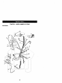
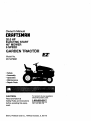
Owner's Manual
CRAFTSMAN
20.0 HP
ELECTRIC START
46" MOWER
6 SPEED
GARDEN TRAC
Model No.
917.273031
• Safety
• Assembly
• Operation
• Maintenance
• Repair Parts
CAUTION:
Read and follow all
Safety Rules and Instructions
before operating this equipment.
Seam,
Roebuck and Co., Hoffman
For answers to your questions
about this product, Call:
1-800-659-5917
Sears Craftsman
Help Une
5 am. 5 pm,Mort- Sat
Estates,
IL 60179
Warranty
,,,,,..,,.,,,,,o,.,,,,,.o,
...........
M_ntanance .........................................
19
Serviceand Adjustments......................23
Storage.................................................31
Troubleshooting
....................................32
Repair Parts.........................................36
PartsOrdering.......................Back Cover
._oo.,oo....2
Safety Rules ...........................................
2
- _embly
..............................
8
OpereUon, .._-_...:.:::.:.._
............................. 12
Maintenance Schedule ......................... lg
LIMITED TWO YEAR WARRANTY ON CRAFTSMAN
RIDING EQUIPMENT
For two (2) years from the date of purchase, if this Craftsman Riding Equipment is maintained, lubricated and tuned up according to the instructions in the owner's manual,
Sears will repair or replace, free of charge, any parts found to be defective in material or
workmanship.
This Warranty does not cover:.
• Expendable items which become wom during normal usa, such as blades, spark
plugs, air cleaners, belts, etc.
• Tire replacement or repair caused by punctures from outside objects, such as nails,
thorns, stumps, or glass.
• Repairs necessary because of operator abuse, negligence, improper storage or accident or the failure to maintain the equipment according to the instructions contained in
the owner's manual.
• Riding equipment used for commercial or rental purposes.
LIMITED 90 DAY WARRANTY ON BA]-I'ERY
For ninety (90) days from date of purchase, if any battery included with this riding equipment proves defective in material or workmanship and our testing determines the battery will not hold a charge, Sears will replace the battery at no charge. In-home warranty
service on your Craftsman riding equipment is available at no charge for 30 days from
the date of pumhasa. Please contact your nearest service center. After 30 days from the
date of purchase, warranty service is available by taking your Craftsman riding equipment to your nearest Sears Service Center. (In-home warranty service will still be available after 30 days from the date of purchase but a standard trip charge will apply). This
warranty applies only while this product is in the United States. This Warranty gives you
specific legal rights, and you may also have other rights which may vary from state to
state.
Sears, Roebuck and Co., D/817 WA, Hoffman Estates, IL 60179
GENERAL
OPERATION
• Never carrypassengers.
• Do not mowin reverse unlessabsolutely necessary.Alwayslookdownand
behindbeforeand whilebacking.
• Be aware of the mowerdischargedirection and do not point it at anyone. Do
notoperatethe mowerwithouteither
the entiregrasscatcher or the guard in
place.
• Slow downbefore turning.
• Never leave a runningmachineunattended.Alwaysturnoff blades,set parking broke,stop engine,and remove
keys beforedismounting.
• Read, understand, and follow all instructions in the manual and on the machine
before starting.
• Only allow responsible adults, who are
familiar with the instructions, to operate
the machine.
• Clear the area of objects such as rocks,
toys, wire, etc., which could be picked
up and thrown by the b/ade.
• Be sure the area is clear of other people
befef_ mowing. Stop machine it anyone
enters the area.
2
• Turn off blades when not mowing.
• Stop engine before removing grass
catcher or unclogging chute.
• Mow only in daylight or good artificial
light.
• Do not operate the machine while under
the influence of alcohol or drugs.
o- Watch for traffic when operating near or
crossing roadways.
• Use extra care when loading or unloading the machine into a trailer or track.
SLOPE OPERATION
Slopes are a major factor related to lossof-control and tipover accidents, which
can result in severe injury or death. All
slopes require extra caution. If you cannot
back up the slope or if you feel uneasy on
it, do not mow it.
DO:
• Mow up and down slopes, not across.
• Remove obstacles such as rocks, tree
limbs, etc.
• Watch for holes, ruts, or bumps. Uneven
terrain could overturn the machine. Tall
gross can hide obstacles.
• Use slow speed. Choose a low gear so
that you will not have to stop or shift
while on the slope.
• Follow the manufacturer's recommendatioos for wheel weights or counterwe_hts to improve stability.
• Use extra care with grass catchers or
other attachments, These can change
the stability of the machine.
• Keep all movement on the slopes slow
and gradual. Do not make sudden
changes in speed or direction.
• Avo'KLstarting or stopping on a slope, if
flms lose traction, disengage the blades
and proceed slowly straight down the
slope.
DO NOT:
• Do nottum on slopes unless necessary,
and then, turn slowly and gradually
downhill, it possible.
• Do not mow near drop-offs, ditches, or
embankments. The mower could suddenly tum over if a wheel is over the
edge of a cliff or ditch, or if an edge
caves in.
• Do g_ mow on wet grass. Reduced
traction could cause sliding.
• Do nottry tostabilizethe machine by
pottingyourfootc_nthe ground.
• Do not usegrasscatcher on steep
slopes.
CHILDREN
Tragicaccidentscan occurif the operator
is not alert to'thepresenceof children.
Childrenare often attreoted to the
machineand the mowingactivity.Never
assumethat childrenwill remainwhere
you lest sew them.
• Keep childrenout ofthe mowingarea
and underthewatchfulcare of another
responsibleadult.
• Be alert and turnmachine offif children
enter the area.
• Beforeand when backing,lookbehind
and downfor small chiktren.
• Never carrychildren.They may fall off
and be seriouslyinjuredor interferewith
safe machineoperation.
• Never allowchildrento operatethe
machine.
• Use extracare when approachingblind
comers,shrubs,trees, or otherobjects
that may obscurevision.
SERVICE
• Use extracare in handlinggasolineand
otherfuels.They are flammableand
vaporsare explosive.
Use onlyan approvedcontainer.
Never removegas cap or add fuel
with the engine running.Allowengineto coolbeforerefueling.Do not
smoke.
Never refuelthe machineindoors.
Never storethe machineor fuel
container insidewhere there is an
openflame, such as a water heater.
• Never mn a machineinsidea closed
area.
attachment bolts,tightand keepequip
mentin goodcondition.
tamperwithsafety
devices.
i Never
sep nutsand
bolts,especiallyblade
Checktheirproperoperationreguledy.
Keep machinefree of grass, leaves, or
otherdebdsbuild-up.Clean oilor fuel
spillage.Allowmachineto coolbefore
storing.
• Stop and inspectthe equipmentif you
strike an object.Repair,if necessary,
before restarting.
• Never
makea<_ustments
orrepairs
with
theengine
running.
• Grass
catcher
components
aresubject
towear,damage,
anddeterioration,
whichcould exposemoving portsor
• Mower blades are sharp and can cut.
Wrap the blade(s) or wear gloves,and
use extra caution when servicing them.
• Check brake operation frequently.
Adjust and service as required.
allowobjectsto be thrown.Frequently
checkcomponentsand replacewith
" manu|acturer'srecommendedpods,
when necessary.
• Be sure the area is clear ol other people
before mowing, Stop machine if anyone
enters the area.
• Never carry passengers.
• Do not mow in reverse unless absolutely necessary, Always look down and
behind before and while backing.
• Never camj children. They may fall off
and be seriously injured or interfere with
safe machine operation.
• Keep children out of the mowing area
and under the watchful care of another
responsible adult.
• Be aied and turn machine off if chgdren
enter the area.
• Before and when backing, look behind
and down for small children.
• Mow up and down slopes (15 ° Max), not
acrosS.
• Remove obstacles such as rocks, tree
limbs, etc.
• Watch for holes, ruts, or bumps. Uneven
terrain could overturn the machine. Tall
grass can hide obstacles.
• Use slow speed. Choose a low gear so
that you will not have to stop or shift
while on the slope.
• Avoidstarting or stepping on a slope; If
tires lose traction, disengage the blades
and proceed slowly straight down the
slope.
• Do nottum on slopes unless necessary,
and then, turn slowly and gradually
downhill, if posslbla.
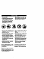
_Look
for this symbol to point out important safety precautions. It means CAUTIONfl!'BECOME AWARE!I! YOUR SAFETY IS INVOLVED.
_WARNING: The engine exhaustfrom
this productcontainschemicalsknownto
the State of Californiato causecancer,
birthdefects,or otherreproductiveharm.
•,CAUTION:
In order to prevent accidental starting when setting up, tranepo_ng,
adjusting or making repairs always disconnect spark plug wire and place wire where
if cannot contact spark plug.
4
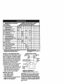
PRODUCT SPECIRGATIONS
GASOLINE
CAPACITY
_ID TYPE:
3.5 GALLONS
UNLEADED
REGULAR
OIL TYPE
_.PI-SFiSG/SH):
SAE 30
(above 32°F)
SAE 5W-30
(below32°F)
OIL CAPACITY:
W/FILTER:
3.5 PINTS
W/O FILTER: 3,0 PINTS
SPARK PLUG:
GAP: .030")
Champion RC12YC
VALVE
;LEARENCE:
INTAKE: .004"-.006"
EXHAUST..004"-.006"
GROUND SPEED LO:
(MPH):
0.7
1.4
2.3
REVERSE:
0.9
HI:
1.7
3.3
5.4
2.1
TIRE PRESSURE: FRONT: 14 PSI
REAR: 10 PSI
CHARGING
SYSTEM:
16 AMPS @ 36(30 RPM
SATrERY:
AMP/FIR:
30
MIN. CCA: 240
CASE SIZE: U1R
BLADE BOLT
TORQUE:
27-35 FT. LBS.
CONGRATULATIONS on your purchase
of a Craftsman Tractor. It has been
designed, engineered and manufactured
to give you the best possible dependability
and performance.
Sbeu.ld_y_ouexperience any problem you
cannot-easily remedy, please contact your
nearest Sears Authodzed Service Center.
We have competent, well-trained technicians and the proper tools to service or
repair this tractor.
Please read and retain this manual. The
instructions will enable you to assemble
and maintain your tractor properly. Always
ol06erve the =SAFETY RULES".
MAINTENANCE AGREEMENT
A Sears MaintenanceAgreementis available on this product.Contactyournearest
Sears storefor details.
CUSTOMER
RESPONSIBILITIES
• Read and observe the safety rules.
• Follow a regular schedule in maintaining, caring for and using your tractor.
• Follow the instructions under =Maintenance" and "Storage" sections of this
owner's manual.
_WARNING:
This tractor is equipped
with an internal combustion engine and
should not be used on or near any unimproved forest-covered, brush-covered or
grass-covered land unless the engine's
exhaust system is equipped with a spark
arrester meeting applicable local or state
laws (if any). If a spark arrester is used, it
should be maintained in effective working
order by the operator.
In the state of California the above is
required by law (Section 4442 of the
California Public Resources Code). Other
states may have similar laws. Federal
laws apply on federal lands. A spark
arrester for the muffler is available through
your nearest Sears Authorized Service
Center (See REPAIR PARTS section of
this manual).
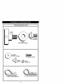
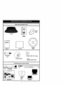
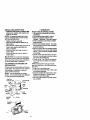
PartsBagcontents
shown
fullsize
(I) Knob
©
m
m
(1) Shoulder
Bolt 5/16-18
(1) Washer
17/32 x 1-3/15 x 12 Gauge
/
(2)washers
3/16 x 3/4 x 16 Gauge
(2)_re_
(2)
Weld
Nuts
#10
#10 x 5/8
@
(2) Lock
Washers #10
(3) Retainer Spdngs (double loop)
(4) Retelner Spdngs (single loop)
6
Parts
packed
separately
incarton
I
Plata
Mulcher
Seat
Video
Cassette
I
I
I
I
I
i
I
I
I
I
i
I
Steering
Wheel
I
Manual
Pads Bag
©
(2) Shoulder
Bolts
(2) Washers 3/8x 7/8 x 14 Gauge
(2) Gauge Wheels
Q(2)
Canter lock Nuts
Parts Bag contents notshown full size
(2) Front Link Assemblies
_==_
(2) Latch Hook
Assemblies
(2) Keys
Steering Sleeve
Steering _''
Wheel
Insert
"-J
Slage Sheet
7
_rlt_
Sleeve
Yournewtractor
hasbeenassembled
atthefactory
withexception
ofthosepartsleft
unassembled
forshipping
purposes.
Toensure
safeandproper
operation
ofyourtractor
allportsandhardware
youassemble
mustbetightened
securely.
Usethecorrect
tools
asnecessary
toinsureproper
tightness.
Review
thevideocassette
before you begin.
TOOLS REQUIRED FOR
ASSEMBLY
"Asocketwrenchset willmake assembly
easier. Standardwrenchsizes you need
are listedbelow.
(1) 9/16" wrench
(1) 3/4" Socketw/
(1) 1/2"wrench
ddve ratchet
(1) Pliers
(1) PhillipsScrew(1) Utilityknife
driver
(1) Tire pressuregauge
When dghtor lefthand is mentionedin
this manual, itmeans, fmm yourpoint of
view, when you are in the operatingposition (seated behindthe steedngwheel).
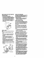
TO REMOVE TRACTOR FROM
CARTON
_--_
_[.._ Hex Bolt
_._
LockWasher
Large Rat
Washer
Steedng
Steedng
Wheel
Wheel
Adapter
Extension
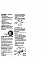
UNPACK CARTON
• Remove all accessible loose parts and
parts boxes from shipping carton (See
page 6).
• Cut, from top to bottom, along lines on
all four comers of shipping carton, and
lay panels flat.
Shaft
,_.___-_
-__..
-'r-_,,,..._'
_ ,. ,
Stssdng
,' I,' ]
,I
• Remove mower and package matedals.
Check for any additional loose parts or
boxes and remove.
BEFORE ROLLING TRACTOR
SKID
A'I-rACH STEERING WHEEL
tssdng
Wheel Insert
IL_.
I
/
dl
I
IMPORTANT: Check for and remove any
staples in skid that may puncture tires
where tractor is to roll off skid.
OFF
TO ROLL TRACTOR OFF SKID (See
Operation section for location end
function of controls)
• Press lift lever plunger and raise attachment lift lever to its highest position.
• Release parking brake by depressing
clutch/brake pedal.
• Place gearshift lever in neutral (N) position.
• Roll tractor forward off skid.
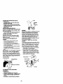
• Remove hex bolt, lock washer and large
fiat washer from steedng shaft.
• Position front wheels of the tractor so
they are pointing straight forward.
• Slid'e-_hesteedng sleeve over the steering shaft.
• Align tabs and press steedhg sleeve
extension into bottom of steedeg wheel.
• Position steedng wheel so cross bars
are horizontal (left to right) and slide
onto steedng wheel adapter.
• Secure steering wheel to steedng shaft
with hex bolt, lock washer and large fiat
washer previously removed. Tighten
securely,
o
• Snap steedng wheel insert into canter
of steedng wheel.
• Remove protective materials from tractor hood and gdlL
8
HOWTOSETUPYOURTRACTOR
CHECK
BATTERY
• Lifthoodto raised po6ition.
CHECK TIRE PRESSURE
The tires on your tractor were ovednflated
at the factory for shipping purposes.
Correct tire pressure is important for best
cuffing performance.
• Reduce tire pressure to PSI shown in
"PRODUCT SPECIFICATIONS" on
page 5 of this manual.
CHECK BRAKE SYSTEM
After you learn how to operate your tractor, check to see that the brake is properly
adjusted. See "TO ADJUST BRAKE" in
the Service and Adjustments section of
this manual.
• If this battery is put into service after
month and year indicated on label (label
located between terminals) charge battery for minimum of one hour at 6-10
amps. (See "BATTERY" in Maintenance
section of this manual for charging
instrucUons).
...-=-.,
..-
.__.
,-
Label
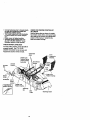
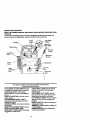
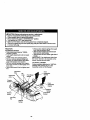
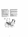
INSTALL MOWER AND DRIVE BELT
Be sure tractor is on level surface and
mower suspension arms are raised with
attachment lift control. Engage parking
brake.
• Cut and remove ties securing anti-sway
bar and belts. Swing anti-sway bar to
left side of mower deck.
• Slide mower under tractor with discharge guard to right side of tractor.
IMPORTANT: Check belt for proper routing in all mower pulley grooves. Install
belt into electric clutch pulley groove.
• install one front link in top hole of the
right hand front mower bracket and right
hand front suspension bracket. Retain
with two single loop retainer spdngs as
shown.
• Install second front link in left hand
front suspension bracket only and
retain with single loop retainer spdng as
shown.
• Turn height adjustment knob counterclockwise until it stops.
• Lower mower linkage with attachment
lift control.
• Place the left hand suspension arm on
inward pointing deck pin. If necessary,
rock and raise front of mower to align
deck pin with the hole in suspension
arm. Retain with double loop retainer
spdng with loops down as shown.
• Slide left side of mower back and install
the unattached front link in top hole of
the left hand front mower bracket.
Retain with single loop retainer spdng
as shown.
• Place the dght hand suspension arm on
inward pointing deck pin. If necessary,
rock and raise front otmower to align
deck pin with the hole in suspension
arm. Retain with double loop retainer
spring with loops down as shown.
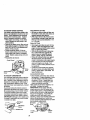
INSTALL SEAT
Adjust seat before tightening adjustment
knob.
• Remove cardboard packing on seat
pan.
• Place seat on seat pan and assemble
shoulder bolt. Tighten shoulder bolt
securely.
• Assemble adjustment knob and flat
washer loosely. Do not tighten.
• Lower seat into operating position and
sit on seat.
• Slide seat until a comfodable position is
reached which allows you to press
clutch/brake pedal all the way down.
• Get off seat without moving its adjusted
position.
• Raise seat and tighten adjustment knob
securely.
" -_ Seat
Seat Pan
Shoulder
Bolt
Adjustment Knob
9
• Connect
anti-sway
bartochassis
bracketunder left footrest and retain with
doubleloop _r
spring.
CHECK FOR PROPER POSITION OF
ALL BELTS
See the figures that are shown for replacing motion, mower drive, and mower blade
drive belts in the Service and Adjustments
section of this manual. Vedfythatthe
belts are muted correctly.
• Turn height adjustment knob clockwise
to remove slack from mower suspension.
• Raise mower to highest position.
Assemble gauge wheels (See..."TO
ADJUST GAUGE WHEELS in the
Operation section of this manual).
CHECK MOWER LEVELNESS
For best cutti_j results, mower should be
properly leveled. See "TO LEVEL
MOWER HOUSING" in the Service and
Adjustments section of this manual.
Suspension
Arms
Brackets
DoubleLoop
RetainerSpring
(Inward po_r,.g
deck
ShouMer
Ba_
Front
Chassis
Bracket
Retainer Springs
Gauge
Wheel
3/8 Washer 3/8-16
Center
Locknut
DoubleLoop
RetainerSpdng
I Use Pliersfor
Idler
Pulley
10
Discharge Guard
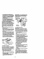
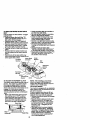
INSTALL MULCHER
PLATE
• Install two latch hooks to mulr.her plate
using ecmw, washer, lock washer, and
wold nut as shown.
NOTE: Pre-sssambie weld nut to latch
hook by inserting wold nut from the top
with hook pointing down.
• Tighten hardware securely.
• Raise and hold deflector shield in upright position.
• Place front of mulcher plate over front of
mower deck opening and slide into
place, as shown.
• Hook front latch into hole on front of
mower deck.
• Hook rear latch into hole on back of
mower deck.
*I CHECKLIST
Please review the following
,/ All assembly instructions have been
completed.
/ No remaining loose parts in carton.
,/Battery is properly prepared and
charged. (Minimum 1 hour at 6 amps).
,/Seat is adjusted comfortably and tightened securely.
,/All tires am properly inflated. (For shipping purposes, the tires were ovednfiated at the factory).
,/Be sure mower deck is propedy leveled
side-to-side/front-to-rear for best cuffing
results. (/ires must be properly inflated
for leveling).
,/Check mower and drive belts. Be sure
they are routed properly around pulleys
and inside all belt keepers.
,/Check wiring. See that all connections
are still secure and wires are propedy
clamped.
While learning how to use your tractor,
pay extra attention to the following important items:
,/" Engine oil is at proper level.
/ Fuel tank is filled with fresh, clean, regular unleaded gasoline.
/ Become familiar with all controls - their
location and function. Operate them
before you start the engine.
/ Be sure brake system is in safe operating condition.
_.CAUTION:
Do not remove discharge
guard from mower. Raise and hold guard
when attaching mulcher plate and allow it
to rest on plate while in operation.
TO CONVERT
DISCHARGING
TO BAGGING
OR
Simply remove mulcher plate and store in
a safe place. Your mower is now ready for
discharging or installation of optional
grass catcher accessory.
NOTE: It is not necessary to change
blades. The mulcher blades are designed
for discharging and bagging also.
Weld Nut
from the To_
Weld
_
Hook Points •
Ic
Latch
H°ok_:_i
Mulcher
Plate
Deflector
/ /
/It
_Lcck
_,-_-Screw
__
Shle,d
11
These
symbols
mayappear
onyourtractororin literaturesuppliedwith the product.
Learnand understandtheirmeaning.
A, =
BA1TERY
CAUTION OR
WARNING
REVERSE
ENGINE ON
ENGINE OFF
OIL PRESSURE
LIGHTS ON
OVER TEMP
UGHT
"11
_
FUEL
CHOKE
MOWER HEIGHT
PARKING BRAKE
LOCKED
UNLOCKED
MOWER LIFT
FORWARD
FAST
r_'= R N H L
AI'rACHMENT
CLUTCH ENGAGED
IGNITION
REVERSE
NEUTRAL
ATTACHMENT
CLUTCH DISENGAGED
HIGH
LOW
KEEP AREA CLEAR
SLOW
t
(®>_(
PARffiNG BRAKE
SLOPE HAZARDS
(SEE SAFETY RULES SECTION)
FREE WHEEL
(.'_,tom_ Mod_ or.y)
DANGER, KEEP HANDS AND FEET AWAY
12
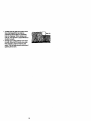
KNOW YOUR TRACTOR
READ THIS OWNER'S MANUAL AND SAFETY RULES BEFORE OPERATING YOUR
TRACTOR
Comparethe illustrationswith yourtractorto familiarizeyourseffwith the locationsof
vadouscontrolsand adjustments.Save thismanualfor futurereference.
Ammeter
Ignition
Switch
Position
Attachment
ThrottleControl
Lift Lever
Plunger
Clutch/Brake
Pedal
Attachment
LiftLever
Choke
Control
Brake
Height
Gear Shift
Lever
Knob
Range
Shift
ever
Our tractors conform to the safety standards of the Amedcan
National Standards Institute.
A'I-rACHMENT CLUTCH SWITCH: Used
to engage the mower blades, or other attachments mounted to your tractor.
LIGHT SWITCH: Turns the headlights on
and off.
THROTTLE CONTROL: Used to control
engine speed.
CLUTCWBRAKE PEDAL: Used for
doclutching and braking the tractor and
starting the engine.
CHOKE CONTROL: Used when starting a
cold engine.
HEIGHT ADJUSTMENT KNOB: Used to
adjust the mower cutting height.
GEAR SHIFT LEVER: Selects the speed
and .d.d._oction
of the tractor.
RANGE SHIFT LEVER: Allows high (H)
and low (L) speed for all forward and
reverse gears.
A'n'ACHMENT LIFT LEVER: Used to
raise and lower the mower dock or other
attachments mounted to your tractor.
LIFT LEVER PLUNGER: Used to release
attachment lift lever when changing its
position.
IGNITION SWITCH: Used for starting and
stopping the engine.
AMMETER: Indicates battery charging (+)
or discharging (-).
PARKING BRAKE: Locks clutclVbrake
into the brake position.
13
I[_
eyes, which can result in severe eye damage. Always wear safety glasses
or eye shields while operating your tractor or performing any adjustments or
repairs.
We recommend
a wide
vision safety
mask
over spectacles,
stanTheoperation
ofanytractor
canresult
inforeign
objects
thrown
intoor
the
dard safety glasses.
HOW TO USE YOUR TRACTOR
Your tractor is _luipped with an operator
.presence sensing switch. When engine is
running, any attempt by the operator to
leave the seat without first setting.the
parking brake will shut off the engine.
TO SET PARKING BRAKE
• Depress clutch/brake pedal into full
"BRAKE" position and hold.
• Place parking brake lever in "ENGAGED" position and release pressure
from clutch/brake pedal. Pedal should
remain in "BRAKE" position. Make sure
parking brake will hold tractor secure.
Push-Into
=Disengaged'
AttachmentClutch
Choke
Control
SwitchPull Out To
Brake
Lever
Ped_ "Ddve"
Podton
STOPPING
MOWER BLADES
• To stop mower blades, move attachment clutch switch to "DISENGAGED"
pcaition.
GROUND DRIVE
• To stopground ddve, depress
clutch/brake pedal into full "BRAKE"
position.
• Move gearshift lever to neutral (N)
position.
ENGINE
• Move throttle control to slow position.
NOTE: Failure to move throttle control to
_eoiwpo6ition and allowing engine to idle
re stopping may cause engine to
-bacldire'.
•Tum ign_on key to "OFF" position and
remo.ve key. Always remove key when
leav_ tractor to prevent unauthodzed
use.
• Never use choke to stop engine.
I
I
II
I
IMPORTANT: Leaving the ignition switch
in any position other than =OFF' will cause
the battery to be discharged (dead).
NOTE: Under certain conditions when
tractor is standing idle with the engine running, hot engine exhaust gases may
cause "browning"of grass. To eliminate
this possibility, always stop engine when
stopping tractor on grass areas.
_. CAUTION: Always stop tractor completely, as descn'bed above, before leaving
the operator's position; to empty grass
catcher, etc.
THROTTLE CONTROL
Always operate engine at full throttle.
Operating engine at less than full throttle reduces the battery charging rate.
• Full throttle offers the best bagging and
mower performance.
CHOKE CONTROL
Use choke control whenever you are starting a cold engine. Do not use to stad a
warm engine.
• To engage choke control, pull knob out.
Slowly push knob in to disengage.
TO MOVE FORWARD AND BACKWARD
The direction and speed of movement is
controlled by the gearshift lever.
• Start tractor with clutch/brake pedal
depressed and gearshift lever in neutral
(N)position.
• Move gearshift and range shift levers to
desired position.
• Slowly release clutch/brake pedal to
start movement.
IMPORTANT: Bdng tractor to a complete
stop before shifting or changing gears.
Failure to de so will shorten the useful life
of your transaxle.
TO ADJUST MOWER cu'rrlNG HEIGHT
The cuffing height is controlled by turning
the height adjustment knob in desired
direction.
• "rum knob clockwise (C,) to raise cutting
neight.
Turn knob counterclockwise (0) to
lower cuffing height.
The cutting height range is approximately
1-1/2" to 4-I/2". The heights are measured from the ground to the blade tip with
the engine cot running. These heights are
approximate and may vary depending
upon soil conditions, height of grass and
14 types of grass being mowed.
• Theaverage
lawnshould
becutto
approximately
2-1/2inchesdudng
the
coolseason
andtoover3 inches
during
hotmonths.Forhealthier
andbetter
looking
lawns,
mowoftenandafter
moderate growth.
• For best cutting performance, grass
over 6 inches in height should be
mowed twice. Make the first cut relatively high; the second to desired height.
" TO ADJUST GAUGE WHEELS
Gauge wheels are properly adjusted
when they are slightly oft the ground when
mower is at the desired cutting height in
operating position. Gauge wheels then
keep the deck in proper position to help
prevent scalping in most terrain conditions.
• Adjust gauge wheels with tractor on a
flat level surface.
• Adjust mower to desired cutting height
(See "TO ADJUST MOWER CU'I-I'ING
HEIGHT" in the Operation section of
this manual).
• With mower in desired height of cut position, gauge wheels should be assembled so they are slightly off the ground.
Install gauge wheel in appropriate hole
with shoulder bolt, 3/8 washer, and 3/816 Iocknut and tighten securely.
• Repeat for opposite side installing
gauge wheel in same adjustment hole.
Bracket
3/8-16
Locknut
Shoulder Bolt
3/8 Washer
Gauge Wheel
TOO -E; ATE
MOWE.
Your tractor is equipped with an operator
presence sensing switch. Any attempt by
the operator to leave the seat with the
engine running and the attachment clutch
engaged will shut off the engine.
• Select desired height of cut.
• Lower mower with attachment lift contreL
• Start mower blades by engaging attachment clutch control.
• TO STOP MOWER BLADES - disengage attachment clutch control.
_,CAUTION:
Do not operate the mower
without either the entire grass catcher, on
mowers so equipped, or the discharge
guard in place.
AttachmentClutch
SwitchPullOut To
,
.
I _°_li_,,Y,._-t
_'_,_ ")"W-_
AttachmentUft Lever
HighPosl_on
. /
Low
7
II II f Dischargs
_-JrTi\ Guard
TO OPERATE ON HILLS
_,CAUTION:
Do not drive up or down
hills with slopes greater than 15° and do
not drive across any slope. Use the slope
guide provided at the back of this manual.
-• Choose the slowest speed before starting up or down hills.
• Avoid stopping or changing speed on
hills.
• If slowing is necessary, move throttle
control lever to slower position.
• If stopping is absolutely necessary, push
clutch/brake pedal quickly to brake position and engage parking brake.
• Move gearshift lever to I st gear and
range shift laver to low (L) position, Be
sure you have allowed room for tractor
to roll slightly as you restart movement.
• To restart movement, slowly release
parking brake and clutch/brake pedal.
• Make all tums slowly.
TO TRANSPORT
• Raise attachment lift to highest position
with attachment lift control.
• When pushing or towing your tractor, be
sure gearshift lever is in neutral (N)
position.
• Do not push or tow tractor at more than
five (5) MPH.
NOTE: To protect hood from damage
when transpoding your tractor on a truck
or a trailer, be sure hood is closed and
secured to tractor. Use an appropriate
means of tying hood to tractor (rope, cord,
etc.).
15
TOWING
CARTSANDOTHER
ATTACHMENTS
Towonlytheattachments that are recom-
,_CAtrrlON:
nil to bottom of gas tank
filler neck. Do not overfill. W'c)e off any
spilled oil or fuel. Do not store, spill or use
mandedbyand complywithspecifications
gasoline near an open flame.
ofthe manufacturerof yourtractor.Use
TO START ENGINE
commonsense when towing.Tooheavy of
a load, whileon a slope,is dangerous.
"13ros
can losetractionwith the groundand
causeyou to lose controlof yourtractor.
BEFORE STARTING THE ENGINE
CHECK ENGINE OIL LEVEL
shipped, from the factory, already filled
T he summer
engine inweight
your tractor
has been
with
oil.
Check engine oil with tractor on level
ground.
• Unthreed and remove oil fill cap/dip
suck;, wipe oil off. Reinsed the dipstick
into the tube and rest oil fill cap on the
tube. Do not thread the cap onto the
tube. Remove and read oil level. If necessary, add oil until "FULL" mark on
dipstick is reached. Do not overfill.
• For cold weather operation you should
change oil for easier starting (See "OIL
VISCOSITY CHART" in the Customer
Responsibilities section of this manual).
• To cnange engine oil, see the Customer
Responsibilities section in this manual.
ADO GASOLINE
• Fill fuel tank. Use fresh, clean, regular
unleaded gasoline with a minimum of 87
octane. (Use of leaded gasoline will
increase carbon and lead oxide
deposits and reduce valve life). Do not
mix oil with gasoline. Purchase fuel in
quantities that can be used within 30
days to assure fuel freshness.
IMPORTANT: When operating in temperatures below 32°F(0°C), use fresh, clean
winter grade gasoline to help insure good
;old weather starting.
A WARNING: Experience indicates that
zlcohol blended fuels (called gasohol or
Jsing ethanol or methanol) can attract
noisture which leads to separation and
ormation of acids during storage. Acidic
]as can damage the fuel system of an
=.nginewhile in storage. To avoid engine
)roblems, the fuel system should be empied before storage of 30 days or longer.
)rein the gas tank, start the engine and let
i run until the fuel lines and carburetor are
_mpty. Use freshJuel next season. See
;torege Instructions for additional
fformati_o, Never use engine or
arburetor cleaner products in the fuel
_nk or permanent damage may occur.
16
When starting the engine for the first time
or if the engine has run out of fuel, it will
take extra cranldng time to move fuel from
the tank to the engine.
• Sit on seat in operating position,
depress clutch/brake pedal and set
paddng brake.
• Place gear shift lever in neutral (N)
position.
• Move attachment clutch to "DISENGAGED" position.
• Move throttle control to fast position
Pull choke control out for a cold engine
start attempt. For a warm engine start
attempt the choke control may not be
needed.
NOTE: Before starting, read the warm and
cold starting procedures below.
• Insert key into ignition and turn key
clockwise to =START" position and
release key as soon as engine starts.
Do not run starter continuously for more
than fifteen seconds per minute. If the
engine does not start after several
attempts, push choke control in wait a
few minutes and try again. If engine still
does not start, pull the choke control out
and retry.
WARM WEATHER STARTING (50 ° F
AND ABOVE)
• When engine starts, slowly push choke
control in until the engine begins to run
smoothly. If the engine starts to mn
roughly, pull the choke control out slightly for a few seconds and then continue
to push the control in slowly.
• The attachments and ground drive can
now be used. If the engine does not
accept the load, restart the engine and
allow it to warm up for one minute using
the choke as described above.
• Do not mowgrasswhen it is wet. Wet
grasswillplug mowerand leave undeelrable clumps,Allowgrass to dry
beforemowing.
• Always operate engine at full throttle
when mowing to assurebettermowing
performance and properdischargeof
materiel. Regulategroundspeed by selectinga lowenoughgear to give the
mowerthe bestcuttingperformanceas
well as the qualityofcut desired.
• When operatingattachments,selecta
groundspeed thatwillsuitthe terrain
and give bestperformanceof the attachmentbeingused.
COLD WEATHER STARTING (50° FAND
BELOW)
• When engine starts, slowly push choke
control in un_l the engine begins to run
smoothly. Continue to push the choke
control in smell steps allowing the
engine to accept small changes in
speed and load, until the choke control
is fully in. If the engine starts to run
roughly, pull the choke control out slightly for a few seconds and then continue
to push the control in slowly. This may
require an engine warm-up period from
several seconds to several minutes,
depending on the temperature.
• The attachments can be used during
the engine warm-up period and may
require the choke control be pulled out
slightly.
NOTE: A high altitude (above 3000 feet)
or in cold temperatures (below 32 F) the
carburetor fuel mixture may need to be
adjusted for beat engine performance.
See "TO ADJUST CARBURETOR" in the
Service and Adjustments section of this
manual.
MOWING TIPS
• Tire chains cannot be used when the
mower housing is attached to tractor.
• Mower should be properly leveled for
best mowing performance. See =TO
LEVEL MOWER HOUSING" in the
Service and Adjustments section of this
manual
• The left hand side of mower should be
used for trimming.
• Drive so that clippings are discharged
onto the area that has been cut. Have
the out area to the right of the tractor.
This will result in a more even distributi0_of clippings and more uniform cutting.
• When mowing large areas, start by turning to the right so that clippings will discharge away from shrubs, fences, driveways, etc. After one or two rounds, mow
in the opposite direction making left
hand turns until finished.
• It grass is extremely tall, it should be
mowed twice to reduce load and possible fire hazard from dried clippings.
Make first cut relatively high; the second
to the desired height.
MULCHING
MOWING
TIPS
IMPORTANT: For best performance, keep
mower housing free of built-up grass and
trash. Clean after each use.
• The special mulching blade will recut
the grass clippings many times and
reduce them in size so that as they fall
onto the lawn they will disperse into the
grass and not be noticed. Also, the
mulched grass will biodegrade quickly
to provide nutrients for the lawn. Always
mulch with your highest engine (blade)
speed as this will provide the best recutting action of the blades.
• Avoid cutting your lawn when it is wet.
Wet grass tends to form clumps and
interferes with the mulching action. The
best time to mow your lawn is the early
aftemoon. At this time the grass has
dried and theJlewly cut area will not be
exposed to the direct sun.
• For best results, adjust the mower cutting height so that the mower cuts off
only the tpp one-third of the grass
blades. For extremely heavy mulching,
reduce your width of cut on each pass
and mow slowly.
17
• Certain
typee
ofgrassandgrees
cond'P
tionsmayrequire
thatanareabe
mulched
asecond
timetocompletely
hidethec{ipping_
Whendoinga secondcut,mowacrossorperpendicular
to
thefirstcutpath.
• Change your cutting pattem from week
to week. Mow north to south one week
then change to east to west the next
week. This will help prevent matting and
graining of the lawn.
18
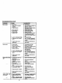
FILL IN DATES
AS YOU COMPLETE
REGULAR
SERVICE
MAINTENANCE
Check
SCHEDULE Z__f___S
Brake Operation
Check Tim Pressure
1_
Check Operator Presence
Interlock Systems
Shaq>ecVReplsce
T
Lubrication
0
Check
R
If
Mower
(l_
t/
I/,
Blades
Id#'4
Chart
V'
Battery Level
C_anBattery
andTerminals
ll/
I_/
Belt(s)
Drive Beh($) Tension
Check
Oil Level
Change
Engine
IV_
Te ns'_n
AdJust Motion
Engine
I_ /
l_i
Check Transaxla Cooi'_g
Adjust Elsde
11_$
(_s
I_
I_
Oi_
I_1,=,:
V p
E
Clean
Air Fk*ter
I_a
N
Clean
Air Screen
ik_z
G
Inspect
HE
ReplaceEngine
Oil Filter
(If equipped)
Clean
Cooling
Fins
I_1,;
I_2
Repklce
Replace
Spark Plug
Air Filter Paper
_2
Replace
Fuel Fitter
MuffierlEpark
E DATES
and
T
R Check
forLooseFastenara
A
E_VIC
V'
An'ester
Cartr_ge
V'
,
1 - Change r_te _qm whe*l opemL_ngunder s beery Io_ 0t In hl_ ambienl _turl4.
2. Sm',_e more on=n wh_,eoperating in dlrlyor dm_/¢:o_ltk)n_
3. If equlpped with og flier. ©hange olle.4er/50 howe.
4 - Repll¢o bia4ee mote often when mowing in m_dy sda.
GENERAL
RECOMMENDATIONS
The warranty on this tractor does not cover
items that have been subjected to operator
abuse or negligence. To receive full value
from the warranty, operator must maintain
tractor as instructed in this manual. Some
adjustments will need to be made periodically to propedy maintain your tractor.
All adjustments in the Service and
Adjustments section of this manual should
be c'hecl_edat least once each season.
• Once a year you should replace the
spark plug, clean or replace air filter, and
check blades and belts for wear. A new
spark plug and clean air filter assure
proper air-fuel mixture and help your
engine run better and last longer.
BEFORE EACH USE
• Check engine oil level.
• Check brake operation.
• Check tire pressure.
• Chec k operator presence and interlock
sy..stemsfor proper operation,
• CT_eckfor loose fasteners,
S. ff eq_pp_ _11h_mmbll
tr/llem.
6 - Not r=_e_ # _
wi_ _
7. T_
_
L,de plvolbolt to _ ft._.
Do n¢4e_wl_ht_.
b_tq_
m_,_'num.
LUBRICATION CHART
Zerk
Beadn
Zerk
Wheel
Beadng
Zerk
O SAE 30 or 10w30 MotorOIL
O General PurposeGrease
• Refer to Maintenance"Engine"Section
IMPORTANT: Do not oil or grease the pivot
points which have special nylon bear-ings.
Viscous lubricants will attract dust and dirt
that will shorten the life of the serf-lubricating
bearings. If you feel they must be lubricated,
use only a dry, powdered graphite type lubricant sparingly.
19
TRACTOR
Always
obee_ve
safetyruleswhenperforming any maintenance.
BRAKE OPERATION
If tractor requires more than six (6) feet
stopping distance at high speed in highest
gear, then broke must be adjusted. (See
"1"OADJUST BRAKE" in the Service and
Adjustments section of this manual).
TIRES
• Maintain proper air pressure in all tires
(See "PRODUCT SPECIFICATIONS" on
page 5 of this manual).
• Keep tires free of gasoline, oil, or insect
control chemicals which can harm rubber.
• Avoid stump6, stones, deep ruts, sharp
objects and other hazards that may
cause tire damage.
NOTE: To seal tire punctures and prevent
flat tires due to slow leaks, tire sealant
may be_urchased from your local parts
dealer. Tire sealant also prevents tire dry
rot and corrosion.
OPERATOR PRESENCE SYSTEM
Be sure that operator presence and interlock systems are working properly. Ifyour
tractor does not function as described
below, repair the problem immediately.
• The engine should not start unless the
clutch/brake pedal is fully depressed
and attachment clutch control is in the
disengaged position.
• When the engine is running, any
attempt by the operator to leave the
seat without first setting the parking
brake should shut off the engine.
• When the engine is running and the
attachment clutch is engaged, any
attempt by the operator to leave the
seat should shut off the engine.
• The attachment clutch should never
operate unless the operator is in the
seat.
3LADE CAR-E
"or best results mower blades must be
:ept sharp. Replace bent or damaged
)lades.
}LADE REMOVAL
Raise mower to highest position to allow
access to blades.
Remove hex bolt, lock washer and fiat
washer Securing blade.
Install new or re,sharpened blade with
trailing edge up towards deck as shown.
_PORTANT: To ensure proper assembly,
enter hole in blade must align with star
n mandrel assembly.
Reassemble hex bolt, lock washer and
flat washer in exes_ order as shown.
• Tighten bolt securely (27-35 Ft. Lho.
to[orque-ue).
IMPORT/ANT: Blade belt is Grade 8 heat
treated.
TrailingEdge
MandrelAssembly
Blade Center
Hole
._.
Star
_.._--H ex Bolt
°A Grade 8 heat treatedboltcan be
identifiedbysix line_on the bolthead.
TO SHARPEN BLADE
NOTE: We do not recommend sharpening
blade, but if you do, be sure the blade is
balanced.
Care should be taken to keep the blade
balanced. An unbalanced blade will cause
excessive vibration and eventual damage
to mower and engine.
• The blade can be sharpened with a file
or on a grinding wheel. Do not attempt
to sharpen while it is on the mower.
• To check blade balance, you will need a
5/8" diameter steel bolt, pin, or a cone
balancer. (When using a cone balancer,
follow the instructions supplied with balancer).
NOTE: Do not use a nail for balancing
blade. The lobes of the center hole may
appear to be centered, but are not.
• Slide blade onto an unthreaded portion
of the steel bolt or pin and hold the bolt
or pin'parallal with the ground. If blade
is balanced, it should remain in a horizontal positlan. If either end of the blade
moves downward, sharpen the heavy
end until the blade is balanced.
""_._
5/8" Boif _
Blade
._
BATTERY
Your tractor has a battery charging system
which is sufficient for normal use.
However, periodic charging of the battery
with an automotive charger will extend its
life.
• Keep battery and terminals clean.
• Keep bettery bolts tight.
• Keep small vent holes open.
• Recharge at 6-10 amperes for 1 hour.
2O
TOCLEAN
BA'n'ERY
ANDTERMINALS tractoris not usedfor 50 hoursin one
Corrnsion
anddirtonthebattery
andter- year.
Checkthe crankcaseoil levelbeforestartminals
cancausethebattery
to"leak"
power.
• Remove terminal guard.
• Disconnect BLACK battery cable first
then RED battery cable and remove
battery from tractor.
• Rinse the battery with plain water and
dry.
- • Clean terminals and battery cable ends
with wire brush until bdght.
• Coat terminals with grease or petroleum
jelly.
• Reinstall battery (See =REPLACING
BATTERY in the SERVICE AND
ADJUSTMENTS section of this manual).
V-BELTS
Check V-belts for deterioration and wear
after 100 hours of operation and replace if
necessary. The belts are not adjustable.
Replace belts if they begin to slip from
wear.
TRANSAXLE COOLING
Keep transaxle free from build-up of dirt
and chaff which can restrict cooling.
CHECK TRANSAXLE OIL LEVEL
• Block up rear axle securely.
• Remove left rear wheel by removing
hub bolts.
• Remove filler plug from transaxie. Oil
level must be even with plug threads. If
necessary, fill with SAE 30 motor oil,
API SF, SG or SH. Replace filler plug.
• Reassemble wheel to hub.
Transaxle
ingthe engine and after each eight(8)
hoursof operation."13ghten
oil fillcap/dip
sticksecurelyeach timeyou checkthe oil
level.
TO CHANGE ENGINE OIL
Determine temperature range expected
before oil change. All oil must meet API
service classification SF, SG or SH.
• Be sure tractor is on level surface.
• Oil will drain more freely when warm.
• Catch oil in a suitable container.
• Remove oilfill cap/dipstick. Be careful
not to allow dirt to enter the engine
when changing oil.
• Remove drain plug.
• After oil has drained completely, replace
oil drain plug and tighten securely.
• Refill engine with oil through oil fill dipsticktube. Pour slowly. Doeet overfill.
For approximate capacity see "PRODUCT SPECIFICATIONS" on page 5 of
this manual.
• Use gauge on oil fill cap/dipstick for
checking level. Be sure dipstick cap is
tightened securely for accurate reading.
Keep oil at "FULL" line on dipstick.
Air Screen
Oil Dr_
Plugf
--_
Oil FiIIf
Cap/Dips_ck
,__
CLEAN AIR SCREEN
Air screen must be kept free of dirt and
chaff to prevent engine damage from overheating. Clean with a wire brush or compressed air to remove dirt and stubborn
dded gum fibers.
CLEAN AIR INTAKE/COOLING AREAS
FillerPlug
ENGINE
LUBRICATION
Only use high quality detergent oil rated
with API service classification SF, SG, or
To insure preper cooling, make sure the
SH. Select the oil's SAE viscosity grade
fins, and other
according to your expected operating tem_ ; grass screen, cooling
'
perature,
external surfaces of the engine are kept
clean at all times.
_v_os,vG_
Every 100 hours of operation (more often
under extremely dusty, dirty conditions),
remove the blower housing and other
cooling shrouds. Clean the cooling fins
and external surfaces as necessary. Make
sure the cooling shrouds are reinstalled.
Change the oil after every 50 hours of
operation or at least once a year if the
21
NOTE:Operating
theengine
witha
blocked
grassscreen,
dirtyorplugged
cooling
fins,and/or
cooling
shrouds
removed will cause engine damage due to
overbearing.
AIR FILTER
Yourengine will not run propedyusing a
dirty air filter. Clean the foam pre-cleaner
after every 25 hours of operation or every
season. Service paper cadridge every
100 hours of operation or every season,
whichever occurs first.
Service air cleaner more often under dusty
conditions.
• Remove knobs and cover.
TO SERVICE PRE-CLEANER
• Wash it in liquid detergent and water.
• Squeeze it dry in a clean cloth.
• Saturate it in engine oil. Wrap it in
c_ean, absorbent cloth and squeeze to
remove excess oil.
• If very dirty or damaged, replace precleaner.
TO SERVICE CARTRIDGE
• Clean cadddge by tapping gently on flat
surface. If very dirty or damaged,
replace cadridge.
• Reinstall predeaner cadrdge, cover
and secure with knobs.
IMPORTANT: Petroleum solvents, such
as kerosene, are not to be used to clean
the cadddge. They may cause deterioration of the cadddge. Do not oil cadndge.
Do not use pressurized air to clean or dry
cadridge.
Foem
ENGINE OIL RLTER
Replace the en_.ns oil filter every season
or every other oll change if the tractor is
used more than 100 hours in one year.
MUFFLER
Inspect and replace corroded muffler and
spark arrester (if equipped) as it could create a fire hazard and/or damage.
SPARK PLUGS
Replace spark plugs at the beginning of
each mowing season or aner every 100
hours of operation whichever occurs first.
Spark plug type and gap setting are
shown in =PRODUCT SPECIFICATIONS"
on page 5 of this manual.
IN-LINE FUEL FILTER
The fuel filler should be replaced once
each season. If fuel filter becomes
clogged, obstruclJngfuel flow to carburetor, replacement is required.
• With engine cool, remove filter and plug
fuel line sections.
• Place new fuel filter in position in fuel
line with arrow pointing towards carburetor.
• Be sure there are no fuel line leaks and
clamps are properly positioned.
• Immediatley wipe up any spilled gasoline.
CLEANING
• Clean engine,battery,seat, finish,etc.
of all foreignmatter.
• Keep finished surfacesand wheels free
of all gasoline,oil, ,etc.
• Protectpaintedsurfaceswith automotive type wax.
We do not recommendusinga garden
hose to cleanyour tractorunlessthe electricalsystem,muffler,air filterand carburetor are coveredto keepwater out.Water
in enginecan resultin a shortenedengine
lifo
22
_CAUTION:
Before performing any service or adjustments:
• Depress clutch/brake pedal fully and set parking brake.
• Place gearshift lever in neutral (N) position.
• Place attachment clutch in "DISENGAGED" position.
• Tum ignition key "OFF" and remove key.
• Make sure the blades and all moving pads have completely stopped.
• Disconnect spark plug wire from spark plug and place wire where it cannot come
in contact with plug.
TRACTOR
TO REMOVE MOWER
• Place attachment clutch in =DISENGAGED" position.
• Turn height adjustment knob to lowest
setting.
• Lower mower to its lowest position.
• Remove retainer spring holding antiswaybar to chassis bracket and disengage anti-swaybar from bracket.
• Remove retainer springs from suspension arms at deck and disengage arms
from deck.
• Raise attachment lift to its highest position.
Adjustment
Nuts
Suspension
Arms
• Remove two retainer springs from each
front link and remove links.
• Slide mower forward and remove belt
from electric clutch pulley.
• Slide mower out from under right side of
tractor,
IMPORTANT: If an attachment other than
the mower deck is to be mounted on the
tractor, remove the front links.
TO INSTALL MOWER
Follow procedure described in "INSTALL
MOWER AND DRIVE BELT" in the
Assembly section of this manual.
Front
Lift
Links
Front Mower
Bracket
Bracket
Chassis
Bracket _,
Front
Bracket
Springs
Retainer
Spring
Bracket
Anti-Sway
Bar
Retainer
Sp_ngs
23
TO LEVEL MOWER HOUSING
• To lowerfrontof mower housing,loosen
nut "G" on beth front linksan equal
numberof turns.
• When distance"F"is 1/8" to 1/2" lower
at front than rear,tighten nut"H"against
trunnionon both frontlinks.
• To raise front of mower housing,loosen
nut "H"fromtrunnionon beth front links.
Tightennut =G"on bothfront linksan
equal numberof tums.
• When distance"F"is 1/8" to 1/2" lower
at front than rear,tighten nut "H"
againsttrunnionon both front links.
NOTE: Eachfull turnof nut "G" will
changedim. "F" by approximately3/8".
• Recheck side-to-sideadjustment.
Adjust the mower while tractor is parked
on level ground or driveway. Make sure
tires are properly inflated (See =PRODUCT SPECIFICATIONS').
If tires are
over or undednflated, you will not propedy
adjust your mower.
SIDE-TO-SIDE ADJUSTMENT
• Raise mower to its highest position.
• Measure height from bottom of deck
cud to ground level at front comers of
mower. Distance "A"on both sides of
mower should be the same.
• If adjustment is necessary, make adjustment on one side of mower only.
• To raise one side of mower, tighten lift
link adjustment nut on that side.
• To lower one side of mower, loosen lift
link adjustment nut on that side.
NOTE: Each full turn of adjustment nut
will change mower height about 3/16".
• Recheck measurements after adjusting.
Mandrel
BothFrontUnksShould bel_qualin Length
Bottom
F-V G,o.ndUno
i-JT
FRONT-TO-BACK ADJUSTMENT
IMPORTANT: Deck must be level side-toside. If the following front-to-back adjustment is necessary, be sure to adjust both
front links equally so mower will stay level
side-to-side.
Nut"H'_
To obtain the best cutting results, the
mower housing should be adjusted so the
front is approximately 1/8" to 1/2" lower
than the rear when the mower is in its
highest position.
Check adjustment on right side of tractor.
Measure distance =F" directly in front of
and behind the mandrel at bottom edge of
mower housing as shown.
• Before making any necessary adjustments, check that both front links are
equal in length.
• If links are not equal in length, adjust
one link to same length as other link.
Lthl_
24
TO REPLACE MOWER DRIVE BELT
MOWER DRIVE BELT REMOVAL
• Park tractor on a level surface. Engage
parking brake.
• Remove screws from left hand mandrel
cover and remove cover.
• Roll belt over the top of left hand mandrel pulley.
• Remove belt from electric clutch pulley.
• Remove belt from idler pulleys.
• Remove any dirt or grass clippings
which may have accumulated around
mandrels and entire upper deck surface.
• Check primary idler arm and two idlers
to see that they rotate freely.
Left Hand
Mandrel
Cover
Screws
- Be sure springis securelyhookedto primaryidlerarm and boll in mower housing.
MOWER DRIVE BELTINSTALLATION
• Installbelt in bothidlers. Make sure belt
is in both belt keepersat the idlersas
shown.
• Installnewbelt ontoelectricclutchpulley.
• Roll belt intouppergrooveof left hand
mandrelpulley.
• Carefullycheckbelt routingmakingsure
belt is in the groovescorrectlyand
insidebelt keepers.
• Reassemblelefthandmandrelcover.
Idler
Pulleys
\
Drive Belt
Mandrel
Primary
Idler Arm
Belt
Keepers
25
TO REPLACE MOWER BLADE DRIVE
see thatthey rotatefreely.
BELT
Be sure springis hookedin secondary
Park the tractoron level surface. Engage
i idlerarm
Checksecondan/idlerarm
and id/erto
and sway-herbracket.
parkingbrake.
Installnew belt in lowergrooveof left
Remove mower drivebelt (See '*TO
handmandrelpulley,idlerpulley,and
REPLACE MOWER DRIVE BELl" in
center mandrelpulleyas shown.
this section of this manual).
• Remove mower (See "TO REMOVE
Make
sure
belt
is in all groovesproperly.
belt
over
righthand
mandrelpulley.
MOWER" in thissectionofthis manual). _Roll
Reconnectspring to boltin mower
• Removescrewsfrom right handmanhousingand reinstalldghthand mandrel
- drel coverand remove cover. Unhook
cover.
springfrom bolton mowerhousing.
•
Reinstallmowerto tractor(See
• Carefullyrollbelt off righthandmandrel
"INSTALLMOWER AND DRIVE BELT"
pulley.
in the Assemblysectionofthis manual).
• Remove belt from center mandrelpul• Reassemblemowerdrivebelt (See "TO
ley, idler pulley,and lefthand mandrel
REPLACE MOWER DRIVE BELT" in
pulley.
this sectionof this manual).
• Remove any did or grass whichmay
have accumulatedaroundmandrelsand
entireupper deck surface.
Mower Blade
• Center
LeftHand
Ddve Belt
Mandrel
Idler
Pulley
Right Hand
• Mandrel
Cover
IdlerArm
Sprin
Anti-Sway-Bar
Bracket
Screw
TO ADJUST ATTACHMENT
CLUTCH
NOTE: After installing a new electric
clutch, run tractor at full throttle and
engage and disengage electric clutch 10
cycles to wear in clutch plate.
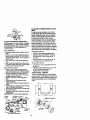
TO ADJUST BRAKE
Your tractor is equipped with an adjustable
brake system which is mounted on the left
side of the transaxle.
If tractor requires more than six (6) feet
stopping distance at high speed in highest gear, then brake must be adjusted.
Depress clutch/brake pedal and engage
parking brake.
• Measure distance between brake opero
ating arm and nut "A"on brake rod.
• If distance is other than 1-3/4", loosen
jam nut and turn nut "A" until distance
becomes 1-3/4". Retighten jam nut
against nut "A'.
• Roadtesttractorforproperstopping
distance as stated above. Readjust if
necessary. If stopping distance is still
greater than six (6) feet in highest gear,
further maintenance is necessary.
Contact your nearest authorizedservice center/department.
The electric clutch should provide years of
service. The clutch has a built-in brake
that stops the pulley within 5 seconds.
Eventually, the intemal brake will wear
which may cause the mower blades to not
en_age, or, to not stop as required.
_,djustmants should be made by your
_earest authorized service center/depart"nent. " "_ , Make sure attachment clutch and ignition switches are in "OFF" position.
, Adjust the three nylon Iocknuts until
space between clutch plate and rotor
measures .012" at all three slot locations cut in the side of brake plate.
Rotor
ClutchPlate
\
L_'_
Broke Plate
26
Nut "A"
Operating'--_
Jam Nut
Arm
TO REPLACE MOTION DRIVE BELT
Park the tractor on level surface. Engage
parkingbrake.
For ease of service there
msa belt installation guide decal on bottom
of left footrest. It is not necessary to
remove mower.
BELT REMOVAL • Engage parking brake (creates slack in
belt).
• Remove mower drive belt from electric
clutch pulleyonly (See ='1"0REPLACE
MOWER DRIVEBEL'F" in this section of
this manual).
• Roll motion drive belt off transaxle pulley.
off
and front
Rollengine
belt offpulley
clutching
idler V-idler
pulleys, pulley.
then
Pull belt out of all belt keepers.
BELT INSTALLATION • Place V part of belt into grooves on
engine pulley and front V-idler, making
sure to route belt inside of belt keepers.
• Put belt coming from V-idler above
midspan belt keeper, then onto clutching idler pulleys as shown.
• Make sure V part of belt engages Vidler.
• Place belt around transaxle pulley,
beginning at top.
V part of belt should engage transaxle
pulley.
• Place long lower section of belt through
loop in midepan belt keeper.
• Check to be sure belt is on proper side
of all belt keepers.
• Reinstall mower drive belt onto electric
clut-ch-pulley.
IMPORTANT: Check brake adjustment.
Engine
Pulley
\
\V-Idler
Clutching _.1 " '"
Flat Idler _.utcnmg
Idler\_
Above_,_
_::=..
° ,_mk=/i[-'l-J
.Keeper, Bat 2.
TO ADJUST STEERING WHEEL ALIGNMENT
If steedng wheel crossbars are not hodzontal (left to right) when wheels are positioned straight forward, remove steedng
wheel and reassemble per instructions in
the Assembly section of this manual.
FRONT WHEEL TOE-IN ADJUSTMENT
Front wheel toe-in is required for proper
steering operation. Toe-in was set at the
factory and adjustment should not be necessary. If parts in the front axle or steedng
mechanism have been replaced or damaged, check toe-in and adjust if necessary.
TO CHECK TOE-IN
• Position front wheels straight ahead.
• Measure distance between wheels at
front and rear of tires (dimensions "A"
and "B").
• Front dimension "A • should be 1/8" to
1/4" less than rear dimension =B".
TO ADJUST TOE-IN
• Loosen jam nuts at adjustment sleeves
on tie rod.
• Adjust tie rod until dimension "A" is 1/8"
to 1/4" less than dimension "B".
• Tighten jam nuts securely.
FRONT WHEEL CAMBER
The front wheel camber is not adjustable
on your tractor. If damage has occurred to
affect the front wheel camber, contact your
nearest authodzed service center/department.
Belt
AdjustmentSleeves
KeePer
I
Jam Nuts
.,,_r_._._j
Pulley
Pulley
As Wewed from Bottom
27
TO REMOVE WHEEL FOR REPAIRS
• Connect the other end of the BLACK
cable to good CHASSIS GROUND,
away from fuel tank and battery.
TO REMOVE CABLES, REVERSE
ORDER • BLACK cable first from chassis and
then from the fully charged battery.
• RED cable lest from both batteries.
FRONT WHEEL
• Blockup axle securely.
• Remove axlecover, retainingringand
weshemto allowwheel removal.
• Repairtire and reassemble.
• Replasewesheraand snap retaining
ringsecurelyin axle groove.
• Replaceaxle cover.
I_EARWHEEL • Blockrear axle securaly.
• Removefive (5) hubboltsto allow
wheel removal.
• Repair tire and reassemble. Replace
and tightenhub bolts securely.
NOTE: To seal tire puncturesand prevent
fist tires due to slow leaks,tire sealant
may be purchasedfrom yourlocalparts
dealer.Tire sealant also preventstire dry
rot and corrosion.
"Positive"(+)
L.H. Panel
REPLACING
BATTERY
4,CAUTION: Do not short battery terminals by allowing a wrench or any other
object to contact both terminals at the
same time. Before connecting battery,
remove metal bracelets, wristwatch
Washers _
RetainingRing
_
*Ne_ltive" (-)
[_-_ql
m'_'__
bands,rings,etc.
Positive terminal must be connected first
to preventsparkingfromaccidental
• Lift hood to raised position.
•grounding.
Remove terminal guard.
• Disconnect BLACK battery cable then
RED battery cable and carefully remove
Axle C%XX__)
TO START ENGINE WITH A WEAK
batteryfrom tractor.
- Installnew batterywithterminalsin
BATTERY
ACAUTION:
Lead-acid batteries generate explosive gases. Keep sparks, flame
and smoking materials away from batteries. Always wear eye protection when
around batteries.
If your battery is too weak to start the
engine, it should be recharged. (See
"BATTERY" in the MAINTENANCE section of this manual).
If '1umper cables" are used for emergency
;tatting, foflo_vthis procedure:
MPORTANT: Your tractor Is equiped with
1 12 volt negative grounded system. The
)ther vehical must also be a 12 volt negaive grounded system. Do not use your
ractor battery to start other vehicles.
"(3 ATTACH JUMPER CABLES Connect each end of the RED cable to
the POSITIVE (+) terminal of each battery, taking care not to short against
chassis.
Connect one end of the BLACK cable to
the NEGATIVE (-) terminal of fully
chargeo'_'t_attery.
same position as old battery.
Reinstall terminal guard.
First connect RED battery cable to post,
tive (+) battery terminal with hex bolt
and keps nut as shown. _ghten secure=,
* _ormect BLACK grounding cable to
negative (-) battery terminal with
remaining hex bolt and keps nut.
Tighten
securely.
• Close terminal access doors.
• Close hood.
Door/
(Red) Cable
Guard
28
Negative
(Black)Cable
TOREPLACE
HEADLIGHT
BULB
• Raisehood.
Hood
• Pull bulb holder out of the hole in the
backaide of the grill.
• Replace bulb inholder and push bulb
holder securely back into the hole in the
backside of the grill.
• Close hood.
INTERLOCKS AND RELAYS
Loose or damaged wiring may cause your
• tractor to run poorly, stop running, or prevent it from starting.
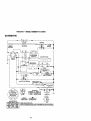
• Check wiring. See electrical widng diagram in the Repair Parts section.
TO REPLACE FUSE
Replace with 30 amp automotive-type
plug-in fuse. The fuse holder is located
behind the dash.
TO ADJUST ATTACHMENT UFT
SPRING
Headlight
Wire
Connector
ENGINE
Maintenance, repair, or replacement of the
emission control devices and systems,
which are being done at the customers
expense, may be performed by any nonroad engine repair establishment or individual. Warranty repairs must be performed by an authorized engine manufacturer's service outlet.
TO ADJUST THRO'I-FLE CONTROL
CABLE
The throttle control has been preset at the
factory and adjustment should not be necessary. Check adjustment as described
below before loosening cable. If adjustment is necessary, proceed as follows:
• With engine not running, move throttle
control lever to fast position.
• Check that swivel is against side of
quarter circle. If it is not, loosen cable
clamp screw and pull cable back until
swivel is against quarter circle. Tighten
cable clamp screw securely.
• While holding spring bushing with
wrench, loosen jam nut.
• Turn adjustment bolt clockwise to
extend spring and reduce lift effort for
heavier attachments.
• Turn adjustment bolt counterclockwise
for lighter attachments.
• Retighten jam nut against spring bushing.
IMPORTANT: Do not adjust for maximum
spring tension when using light attachments such as a mower. Adjust lift lever
spring to aid in lifting attachment. Do not
overpower spring. When removing attachment, always adjust spring tension to its
lowest position.
AdjustmentBolt
SpringBushing
Clamp
Quarter Circle
,/
Jam Nut
TO REMOVE HOOD AND GRILL
ASSEMBLY
• Raise hood.
Unsnap headlight wire connector.
• Stand in front of tractor. Grasp hood at
sides, tilt toward engine and lilt off of
tractor.
• To replace, reverse above procedure.
29
PRELIMINARY SETTING
• Be sure you have a clean air filter, and
the throttle control cable and choke are
adjusted properly (see above).
• With engine off tum idle mixture screw
In (clockwise) closing it finger tight and
then turn out (counterclockwise) 1-1/4
to 1-1/2 tums.
TO ADJUST CHOKE CONTROL
The choke controlhas been presetat the
factoryand adjustmentshouldnotbe necessary. Checkadjuslmantas described
belowbeforelooseningcable. If adjustment is necessary,proceedas follows:
• With enginenot running,movechoke
control(locatedon dash panel)to full
choke position.
_• Removeair cleaner cover,filter and cartridgeplate to expose carburetorchoke
(see "AIR FILTER"in the Maintenance
sectionof this manual).
• Choke shouldbe closed.If it is not,
loosencasingclampscrewand move
choke cable untilchokeis completely
closed.Tightencasingclampscrewsecurely.
• Reassembleair cleaner.
FINAL SETTING
• Start engine and allow to warm for five
minutes. Make final adjustments with
engine running and shift/motion control
lever in neutral (N) position.
• With throttle control lever in slow position, hold throttle lever against idle
speed screw and adjust idle speed
screw to obtain 1200 to 1400 RPM.
• While still holding throttle lever against
idle speed screw, turn idle mixture
screw In (clockwise) until engine begins
to die and then turn out (counterclockwise) until engine runs rough, Turn
screw to a point midway between those
two positions.
• Continue to hold throttle lever against
idle speed screw and adjust idle speed
screw to obtain 900 to 1200 RPM. Release throttle lever.
Choke Closed
Lever
Screw
TO ADJUST CARBURETOR
The carburetor has been preset at the factory and adjustment should not be necessary. However, minor adjustment may be
required to compensate for differences in
fuel, temperature, altitude or load. If the
carburetor does need adjustment, proceed
as follows:
In general, turning the mixture screw in
(clockwise) decreases the supply of fuel to
the engine giving a leaner fuel/air mixture.
Turning the mixture screw out (counter:,lockwise) increases the supply of fuel to
the engine giving a richer fuel/air mixture.
iMPORTANT: Damage to the needles and
:he seats in carburetor may result if screw
s turned in too tight.
IdleMixture
Screw
ACCELERATION TEST
• Move throttle control lever from slow to
fast position. If engine hesitates or dies,
turn idle mixture screw out (counterclockwise) 1/8 turn. Repeat test and
continue to adjust, if necessary, until
engine accelerates smoothly.
High speed stop is factory adjusted. Do
not adjust - damage may result.
IMPORTANT: Never tamper with the
engine governor, which is factory set for
proper engine speed. Overspeeding the
engine above the factory high speed setting can be dangerous. If you think the
engine-governed high speed needs
adjusting, contact your nearest authorized
service center/department, which has
proper equipment and experience to make
any necessary adjustments.
Idle Speed £i--l-_r-----_
Screw_
Throttle
Lever
3O
-
Idle
Mixture
Screw
Immediately
prepare
yourtractorfor storage at the end of the season or if the tractor will not be used for 30 days or more.
,A CAUTION: Never store the tractor with
gasoline in the tank inside a building
where fumes may reach an open flame or
. spark. Allow the engine to cool before storing in any enclosure.
TRACTOR
Remove mower from tractor for winter
storage. This will allow you to clean it thoroughly. Remove all dirt, grease, leaves,
etc. Store in a clean, dry area.
• Clean entire tractor (See =CLEANING"
in the Maintenance section of this manual).
• Inspect and replace belts, if necessary
(See belt replacement instructions in the
Service and Adjustments section of this
manual).
• Lubricate as shown in the Maintenance
section of this manual.
• Be sure that all nuts, bolts and screws
are securely fastened. Inspect moving
parts for damage, breakage and wear.
Replace if necessary.
• Touch up all rusted or chipped paint surfaces; sand lightly before painting.
BATTERY
• Fully charge the battery for storage.
• After a period of time in storage, battery
may require recharging.
• To help prevent corrosion and power
leakage during long periods of storage,
battery cables should be disconnected
and battery cleaned thoroughly (see
"TO CLEAN BATTERY AND TERMINALS" in the Maintenance section of
this manual).
• After cleaning, leave cables disconnected and place cables where they cannot
come in contact with battery terminals.
• If battery is removed from tractor for
storage, do not store battery directly on
concrete or damp surfacas.
Also, experience indicates that alcohol
blended fuels (called gasohol or using
ethanol or methanol) can attract moisture
which leads to separation and formation of
acids during storage. Acidic gas can damage the fuel system of an engine while in
storage.
• Drain the fuel tank.
• Start the engine and let it run until the
fuel lines and carburetor are empty.
• Never use engine or carburetor cleaner
products in the fuel tank or permanent
damage may occur.
• Use fresh fuel next season.
NOTE: Fuel stabilizer is an acceptable
alternative in minimizing the formation of
fuel gum deposits during storage. Add stabilizer to gasoline in fuel tank or storage
container. Always follow the mix ratio
found on stabilizer container. Run engine
at least 10 minutes after adding stabilizer
to allow the stabilizer to reach the carburetor. Do not drain the gas tank and carburetor if using fuel stabilizer.
ENGINE OIL
Drain oil (with engine warm) and replace
with clean engine oil (See =ENGINE" in
the Maintenance section of this manual).
CYLINDER(S)
• Remove spark plug(s).
• Pour one ounce of oil through spark plug
hole(s) into cylinder(s).
• Turn ignition keyto "START" position for
a few seconds to distribute oil.
• Replace with new spark plug(s).
OTHER
• Do not store gasoline from one season
to another.
• Replace your gasoline can if it starts to
rust. Rust and/or dirt in your gasoline will
cause problems.
• If possible, store your tractor indoors
and cover if to give protection from dust
and dirt.
• Cover your tractor with a suitable protective cover that does not retain moisture.
Do not use plastic. Plastic cannot
breathe, which allows condensation to
form and cause your tractor to rust.
IMPORTANT: Never cover tractor while
engine and exhaust areas are still warm.
ENGINE
FUEL SYSTEM
IMPORTANT: It is important to prevent
gum deposits from forming in essential
fuel system parts such as carburetor, fuel
filte_el
hose, or tank during storage.
31
TROUBLESHOOTING
CHART
PROBLEM
CAUSE
* Out of fuel.
WUlootstart
• Enginevalvesout of
adjustment.
CORRECTION
i • Fill fuel tank.
I ° See "TO START ENGINE" in
Operation section.
• Wait several minutes before
attempting to start.
• Replace spark plug.
• Clean/replace air fitier.
• Replace fuel tilter.
I • Drain fuel tank and carburetor, refill tank with fresh
gasoline and replace fuel illtar.
• Check all wiring.
• See "To Adjust Carburetor"
in Service and Adjustments
section.
• Contact an authorized service center.
•
•
•
•
•
•
•
•
•
I•
• Engine not "CHOKED"
properly.
• Engine flooded.
•
•
•
•
Bad spark plug.
Dirtyair filter.
Dirtyfuel tilter.
Water in fuel.
• Loose or damaged wiring.
• Carburetor out of adjustment.
Hard to start
Dirty air filter.
Bad spark plug.
Weak or dead battery.
Dirty fuel filter.
Stale or dirty fuel.
• Loose or damaged wiring.
• Carburetor out of adjustment.
• Engine valves out of
adjustment.
Clearv'replace air tilter,
Replace spark plug.
Recharge or replace battery,
Replace fuel filter.
Drain fuel tank and refill with
fresh _soline.
I" Check all wiring.
• See "To Adjust Carburetor"
in Service and Adjustments
section.
! • Contact an authorized service center.
b
Engine will not turn
_ver
• Clutch/brake pedal not
depressed.
• Attachment clutch is
engaged.
• Weak or dead battery.
• Blown fuse,
• Corroded battery terminals.
• Loose or damaged widng.
• Faulty ignition switch.
• Faulty solenoid or starter.
• Faultyoperatorpresence
switch(as).
;ngine clicks but
lill net start
• Weak or dead battery.
Co_odedbatteryterminala.
• Loose ordamagedwidng.
• Faultysolenoidorstarte_
32
• Depress clutclvbrake pedal.
• Disengage attachment
clutch.
• Recharge or replace battery.
• Replace fuse.
• Clean battery terminals.
i • Check all wiring.
• Check/replece ignition
switch.
• Check/replace solenoid or
starter.
• Contact an authorized service center.
Rechargeor replace battery.
Clean batteryterminals.
Checkall wiring.
• Check/replacesolenoidor
starter.
TROUBLESHOO_NG
CHART
PROBLEM
CAUSE
CORRECTION
Lees M power
• Cuffing too much
graes/too fast.
• Throttle in "CHOKE" position.
• Build-up of grass, leaves
and trash under mower.
• Dirty air rifler.
• Low oil level/dirty oil.
• Faulty spark plug.
, Set in "Higher Cut" position/raduce speed.
• Adjust throttle control.
• Dirtyfuel filter.
• Stale or dirtyfuel.
• Water in fuel.
• Spark plug wire loose.
• Dirty engine air
screen/fins.
• Dirty/clogged muffler.
• Loose or damaged wiring.
• Carburetor out of adjustmenL
• Engine valvesoutof
adjustmenL
Excessive vibration
• Wom, bent or loose blade.
• Bent blade mandrel.
• Loose/damagedpart(s).
Engine continues to
run when operator
leaves seat with attachment dutch
engaged-
Poor cut- uneven
• Clean underside of mower
housing.
• Clean/replace air filter.
• Check oil lovel/change oil.
• Clean and regap or change
spark plug.
• Replace fuel filter.
• Drain fuel tank and refill with
fresh gasoline.
• Drain fuel tank and carburetor, refill tank with fresh
gasoline and replace fuel filter.
• Connect and tighten spark
plug wire.
• Clean engine air screen/fins.
• Clean/replace muffler.
• Check all wiring.
• See "ToAdjust Carburetor" in
Service and Adjustments
section.
• Contact an authorized service center.
• Replace blade. 13ghten blade
bolt.
• Replace blade mandrel.
• Tighten loose port(s).
Replace damaged pads.
• Faultyoperator-safety
presencecontrolsystem.
• Check wiring, switches end
connections. If not
corrected, contact an authorized service center/
department
• Worn, bent or loose blade.
• Replace blade. Tighten
blade bolt.
• Level mower deck.
• Clean underside of mower
housing.
• Replace blade mandrel.
• Clean around mandrels to
open vent holes.
• Mower deck not level.
• Buildupofgrass,leaves,
and trash undermower.
• Bent blade mandrel.
• Cloggedmowerdeckvent
holesfrom buildupof
grass,leaves, and trash
aroundmandrels.
33
TROUBLESHOOTING
PROBLEM
Mower blades will
not rotate
CHART
CAUSE
CORRECTION
• Obstruction in clutch mechanism.
• Remove obetruction.
• Worn/damaged mower
drive belt.
• Frozen idler pulley.
• Frozen blade mandrel.
Poor grass discharge
• Replace idler pulley.
• Replace blade mandrel.
• Engine speed too slow.
•
•
•
•
•
•
•
•
•
•
Headlight(s)not
working(if so
equipped)
i • Replace mower drive belt.
•
•
•
•
i • Place throttle control in
"FAST" position.
Travel speed too fast.
• Shift to slower speed.
Wet grass.
• Allow grass to dry before
mowing.
Mower deck not level.
• Level mower deck.
Low/uneven tire air pros• Check tires for proper air
sure.
pressure.
Worn, bent or loose blade.
• Replecelsharpen blade.
Tighten blade bolt.
Buildup of grass, leaves
• Clean underside of mower
and trash under mower.
housing.
Mower ddve belt wom.
• Replace mower drive belt.
Blades improperly installed. • Reinstall blades sharp edge
down.
Improper blades used.
• Replace with blades listed in
this manual.
Clogged mower deck vent
• Clean around mandrels to
holes from buildup of
open vent holes.
grass, leaves, and trash
around mandrels.
Switch is "OFF".
Bulb(s) burned out.
Faulty light switch.
Loose or damaged widng.
• Blown fuse.
Batterywillnot
charge
• Bad batterycell(s).
• Poorcable connections.
Engine =backfires"
when turning engine
"OFF"
• Faultyregulator(ifso
equipped).
• Faultyalternator.
•
•
•
•
Tum switch=ON".
Replacebulb(s).
Check/replacelightswitch.
Checkwiringand connections.
• Replacefuse,
• Replace battery.
• Check/cleanall connections.
Replaceregulator.
• Replace aifemator.
• Move throttlecontrolto
• Enginethrottlecontrolnot
=SLOW"positionand allow
set at =SLOW"positionfor
to idlefor 30 secondsbefore
30 secondsbeforestopping
stoppingengine.
engine.
34
TRACTOR-- MODELNUMBER917.273031
SCHEMATIC
- ;llllll
[
-
BAI3"ERY
=SOLENOID
AMMETER
;c---i i
;_
,L---IO_ b-------_
t
i
_ E
I
i
H I
i 8
_p
: 0_
t
ELECTRIC CLUTCH
I
I
i
f IGNITIO_
SWITCH
• ....
"_ J
PTO
(NOT OCCUPIED)
_........
,
rj
|
I
_._
J
.........
'- ....
_:L;EL;
I=
LINE
J
__
R£LAYPRESENCE
01
OPERATOR
IGN _TION
L
PLUGS
GAP
SPARK
uNrr
I
(E_UGE CH
J
"_i_N CYL
ENGINES)
FUEL SHUT-OFF SOLENOID
_
REGIJ_T_'__
pOSITION
CIRCUIT
PTO SWITCH
OFF
ON
•
.ELA_
0
REMOVABLE
CONNEC_ONS
IGNITION
NON-REMOVABLE
CONNECTIONS
SWI'FCH
WIRING
INSULATED
CUPS
NOTE: IF WIRING INSULATED
CUPS
UNIT, "i_EY SHOULD BE REPLACED
35
ep__
G+G_B*
C+ FIB÷ E,A+D
HEADLIGHT S
GFC
H
B
DA
WERE REMOVED
FOR SERVICING
OF
TO PROPERLY
SECURE YOUR WIRING.
TRACTOR - - MODEl. NUMBER 917.273031
ELECTRICAL
22
41
TRACTOR - - MODEL NUMBER 917.273031
ELECTRICAL
KEY
PART
NO.
NO.
1
2
DESCRIPTION
144926
74760412
BattePJ
Bolt Hex Head 1/4-20 x 3/4
8
10
7603J
145211
Tray, Batterj
Bolt 1/4-20 x 7.5 Z_c
11
12
16
19
20
21
22
24
25
26
150109
145769
153664
STD551125
73350400
161785
4152J
4206J
146149
108824X
Hold down Battery Dash Mount
Nut push Nylon 1/4"
Switch Interlock push-In
Wasiler, Lock 1/4
Nut, Jam He:( 1/4-20
Harness, Light
Bulb Light
Cabk_, Battery
Cable, Battery
Fuse
27
28
29
30
33
40
41
42
43
45
50
70
81
83
73510400
4207J
160784
163.968
140403
164417
17720408
131563
145673
122822)(
154963
164767
109748X
163996
Nut, Keps Hex 1/4-20 UNC
Cable, Ground
Switch, Ptunger
Switch, Ign
Key, IgcdiJon
Harness Ign.
Screw 1/4-20 x 1/2
Cover, Terminal
Solenokl
Ammeter
Switch, PTO
Harness F-J_ne
Relay Asm.
Socl(et. Lk_ bulb
NOTE: All component dimer,_ons given lb U.S. lbches
1 inch = 25.4 mm
37
TRACTOR - - MODEL NUMBER 917.273031
CHASSIS AND ENCLOSURES
122
38
TRACTOR - - MODEL NUMBER 917.273031
CHASSIS AND ENCLOSURES
KEY
PART
NO.
NO.
DESCRIPTION
1
2
4
5
6
7
8
14
15
16
17
18
19
20
21
150253
140506
73800700
163975
157882
17720408
145166
161023X558
160568
121794X
17490612
160564X558
19131312
STD523715
STD541437
Rail, Frame RH
Drawbar, Gt
Nut, L(_kRex 7/16Unc
DashYTGT2Cyt
Dash, Lower Vgt One Piece
Screw, TndCut 114-20xi/2
Support, Batterj
HondAsm., PntYTGT
Len_AsmHeadllghtBer
Cover, Access
Screw, Thdro_ 3/8-16x314
GnJle
Washer 13/82x13/16x12Ga.
Bolt, FinHex 3/6-16xl
NutCrownlock
3/8-16Unc
23
24
28
30
31
32
33
34
35
36
37
17490616
145243X558
145244X558
145051X014
161419
161327
161326
142131
19111116
74780512
163981X558
39
40
42
43
44
45
47
136961
156111
72140608
136939
136940
154913
17490608
Sc_ewTndrol 3_-16xlTy-Tt
Footrest, RH
Footrest, LH
Saddle. SlkscrVgt
Brace, Supt 1-pc VGT Steedng
Bracket, Pivot Chassis Lh
Bracket, Pivot Chassis Rh
Bracket. Engine Support Rear
Washer 11/82x11/16x16Ga.
Bolt, FinHex 5/16-18x3/4
Fender YTG'r PNT WO/SH Cup
558
Bracket' Axle Front
Bracket, SupportAx_JEngine
Bolt. Carriage 3i6-16xl
Bracket' Spnsn Front Lh
Bracket'SpnsnFrontRh
BracketAsm.,SuspChassisRh
ScrewTndroL 3/8-16 x 1/2
KEY
PART
NO.
NO.
DESCRIPTION
50
52
56
58
60
63
67
68
70
84
85
86
88
152728 .
STD541431
155914
137113
17490620
19131514
156793
17480508
137159
142992
144911
74760716
STD551143
Bracket, Chassis Front
Nut, Crownlod( 5/16-18 Unc
Bracket Asm,, Susp Chass_ Lh
Bracket Asm., Fender
ScrewThdrol. 3/8-16 x 1-114
Washer 13/32 x 1 x 14 Ga.
Guide, Belt Gear Drive
ScrewThdrol. 5/16.18x 1/2
90
STD551237
Washer, Lock External Tooth
3/8
Rail, Frame Lh
Push Nut, Nylon
Screw, Tndr_ Hex Head ;Snc
Mwr
Washer 13/82 x I x 16 Ga.
Screw Hex Wshd 8-18 x 7/8
Screw Sltd H Hd W/Tin Washer
Bolt Fin Hex 7/16-14x I Gr. 5
Cupholder Y'FGT
Bo, Shoulder 5/16-18 "Jr
Magnet YTGT
Stdker Plate YTGT
Bracket Dash Rh
Bracket Dash Lh
Fastener Nut Pa_
91
95
106
156586
105531X
138776
Guide, Belt Mid Span
Stop, Over Center Mower
Bracket, Support Tmnsaxte
Bo_tF3n Hex 7116-14 UNC x 1
Washer. Lock Hvy Hid S W
7/16
120
19131616
122
161464
130
17521312
137
74780716
138
163975X428
139
161330
140
163806
141
1638G5
142
161897
144
161900
147
162967
148
164655
Extrusion Bumper
Duct Heat Hood GTCV
150
161237
NOTE: All component dimensions given _1U.S. inches
1 inch = 25.4 mm
39
TRACTOR - - MODEL NUMBER 917.273031
GROUND DRIVE
39
36
37
40
TRACTOR - - MODEL NUMBER 917.273031
GROUND DRIVE
KEY
NO.
PART
NO,
1
3
4
5
6
7
8
9
10
11
12
13
14
15
16
17
18
19
21
22
23
24
25
26
27
9858M1
7563R
17490508
STD541437
STD561210
149176
12000(]_4
140080
142509
136927
73750800
139419
138901
STD551037
143012
126gO9X
137104
136926
23260412
633AI09
106932X
136925
136923
137552
17490528
28
29
30
34
35
73350600
137213
19131616
124236X
137648
KEY
NO.
DESCRIPTION
Key.Woodruff
Washer, Thrust, A_e
ScrewThdrolS/16-18x3/4
Nut.Crownloc_ 3/8-16
Pin, Cotter
Wheet. HubAssembly
Klip, Ring
Bolt, Hub
Disc, Brake
Yoke, Brake Disc
Nutlook 1/2-20 Unf
Washer. Special
Bushing
Washer 15/32x13/16x16Ga.
Set. Screw 1/4-28 x 3/4
Spdrlg
Lever. Brake
Cam, Brake Disc
Screw, RatHead 1/4-28x3/4
Geamohifl,LeverAssembly
Knob
Suppod, PuokBrake
Puck, BrakeTop
Spdng, Return
Screw. He)( Wsh "l_d.
5/16-18 X 1-3/4
Nut, Hex,._m 3/8-16
Brake, Rod
Washer 13/32 x I x 16 Ga.
Cap, Plunger
Rod, Parldng Brake
36
37
38
39
40
41
42
46
47
48
50
51
52
53
54
55
56
57
59
60
61
62
63
64
65
66
67
68
69
117
PART
NO.
149412
121749X
150035
74321016
5304.1
73661000
8883R
145170
138228
72110612
131494
STD541437
139123
207J
161590
105706X
137153
141756
122253X
122268X
137524
STD551143
74760720
154752
67609
140296
19131312
5142H
136327
73900600
DESCRIPTION
Spdng, Drive Ground
Washer 25/32 x 1-1/4 x 16 Ga.
Ny,ner
Screw, Fin. #10-24 x 1
Actuator, Interlock Switch
Locknut #10-24
Cover, Pedal
Retainer, Spring
Clutch Rod
Bo_ Carriage
Gr. 5
3/8.16 x 1-1/2
Pulley, Idler. Flat
NUt. Crownlook 3/8-16 UNC
Pulley. Idler. Grooved
Washer, Hardened
Clutch, An'n Assembly
Beadng, Idler
V-Belt
Bracket. Shift Rod, Hi-Lo
Shift Red, Hi4-o
Spring Clip, Connecting Link
Pulley, Transaxle
Washer. Lock 7/16
Beth Fin Hex 7116-14 x 1-1/4
Shalt. Clutch/Brake Pedal
Bolt, Shoulder
Washer. Hardened
Washer, Rat
Pin, Roll
Hub, Cover
Nut, Laok Fig. :_16 Uric
NOTE:All oomponentd_nenslensgivenk_U.S. inches
1 inch= 25.4 mm
41
TRACTOR - - MODEL NUMBER 917,273031
STEERING ASSEMBLY
L
15
23
22
31
34
32
27
17
42
19
/
//
/"
16
3S
14
18@
42
TRACTOR - - MODEL NUMBER 917.273031
STEERING ASSEMBLY
KEY
NO.
PART
NO.
DESCRIPTION
1
2
3
4
5
6
7
8
9
10
11
12
13
159944X428
137094
6855M
161849
161848
6266H
121748X
12000029
121232X
74781044
136518
73901000
121749X
Wheel, Steedng
Axle Asm., Fro_
F_ng, Grease
Spindle Asm, LH
Spk_dle Asm., RH
Bearing, RaoeThrust Harden
!fresher 25/32x1-5/Sx16Ga.
Ring, Kllp #T5304-75
Cap, Spindle
Bott, Fin Hex 5/8-11 x 2-3/4
Spacer Bearing A)de Front
Nut, Lock Range 5/8-11 Unc
Washer 25/32 x 1-1/4 x 16 Ga.
14
15
16
17
18
19
20
21
22
23
25
STD551137
STD541537
145103
137347
137155
156011
163887
159945
155105
152927
STD523710
Washer, Lock Hvy Hid Spr 3_
Nut, Lock Center 3_-24 UNF
Shaft Asrn., Steedng
Rod Asm., "i3e Ball J Ball Vgt (Inc. Key No. 36-40)
DraglW(, Ball Joint Sol'_l Vgt
Suppo;t Asm., Steedng Vgt
Boot, Steedng
Adapter, Wheel Steedng
Bushing, Strg. Blk
Screw
Bolt, Fkl Hex 3/8-16 x 1Gr, 5
26
27
28
29
30
31
32
33
34
35
36
37
38
39
40
41
42
44
45
159946X428
3366R
17490612
I o42"_x
12000034
138136
19111610
$1_551131
STD523107
138059
137156
73360600
1(_650X
73700600
109851X
155246
17490508
160135
19132411
Cap, _rneel Steer_g
Beadng, Col, Sltg.
Screw, Thrdrol 3/8-16x3/4
Bearl_,
Ring, Klip Truarc #5304-75
Bushing, NylinerSnap
V_asher 11/3_ x 1 x 10 G_
W'_sher, Lock Hvy H_d Spr 5/16
Bolt, HexHd 5/16-18x3/4
Gear, Sector Stsering
Tie Rod
Jam Nut RH l_read
Joint AS_. Bal RH 11_ead
JamNut LH'nlmad
Joint Asra. Ball LH "lTiread
Bracket Switch Interlock VGT 9"/
ScrewThdrol 5/16-18xt/2Tyt
Exlension, Steedng
Washer 13/":/':/'32
x 1-1/20 x 11 Ga.
NOTE: AJlcompone_d_le_ns
1 Inch= 2,5.4mm
givenin U.S. k_,,es
43
TRACTOR - - MODEL NUMBER 917.273031
ENGINE
21_20
76
39
18
15
32
16
$
-_27
37
39
I SPARK
44
/
29
ARRESTER
KIT
TRACTOR - - MODEL NUMBER 917.273031
ENGINE
KEY
NO.
PART
NO.
DESCRIPTION
1
2
5
7
8
9
10
11
12
15
16
17
18
19
20
21
22
24
25
26
27
28
29
32
33
35
37
38
39
4O
41
42
43
45
47
48
51
54
55
65
69
74
75
76
79
......
161062
Eng_e (See Bceaadown) B&S Model NO.4O77"/7-0122-E1
Muffler,Side 1-1/8 ° g6
13200300
151396
121361X
150828
1(To432X
140923
Elbow STD 90 Dngrea 3/8 - 18 NPT
Muffler Asm Guard
Pulley V-Idler
Keapef Asm. Belt Engine
Bushing
Clutch Bectdc
143996
151346
Pulley Engale VGT Elect Clutch
Tank Fuel Rear 3.50 Yt/Gt 96
109227X
106082X
161493
13290300
164067
17521312
164068
S_:)551237
73920600
3645J
139277
7834R
132920
17490508
STD541437
100405G0
123487X
74780624
17490636
174s<_o64
126197X
STD551143
150_80
128861
142040
19132007
161064
19131414
Pad Spacer
Pad Spacer
Cap Asm Fuel W/Gauge
Plug Oil Drain (Order From Engine Manufacturer)
Contro_ Thro_e
Screw SLTD Hex HD W/PIn Washer
Control Choke
Washer Ext Tooth 3_
Nut Keps 3/8 - 24 UNF
Bushing
Stern Tank Fuel
Fuel Line
Spark Arrester K'd
Thdrol 5/16-18 x 1/2
Nut Lock Hex w/lns. 318 - 16
Washer Lock Hv'/Hlcl Spr 5/16
Clamp Hose
Bolt Fin Flex 3/8 - 16 x 1-1/2
Screw'Ur 3/8-16 x 2-1/4 UNC
Screw TT 3/8-16 x 4 UNC
washer 1-1/200 X 15/32 ID X .250
Washer Lock 7/16
Bolt He)( 7/16 - 20 x 4-1/4 5 Ca. 1.38
Nut Flange 1/4-20 Starter Nut
Spacer Engine
Washor 13/32 x 1-1/4 x 7 Ga.
Manifold Pipe VGT
Washer Flat 13/3Q x 7/8 x 14 Ga.
13280_
19131614
165391
162295
163776
17490612
71070512
Nipple FSpe4-1/2
Washer 13/32 x 1 x 14 Ga.
Gasket Muffler
EIx_w Streat Brass
Shield Heat lutek
Screw Thdrol 3/8-16 x 3/4 _t:i7"
Screw Hex Hd Cap 5/16-18 x 3/4
.
NOTE: AllcompoeantdlrrlenS_.sghienin U,S. inches
1 Inch= 25A mm
45
TRACTOR-- MODELNUMBER917.273031
SEATASSEMBLY
KEYNO,
1
2
3
4
5
6
7
8
10
" 12
13
P_ART
NO.
DESCRIPTION
140124
14_51
140675
127018X
145006
STD541437
124181X
150176
155925
121246X
121248X
Seat
.
Bracket, Pivot Seat
Strap, Fsnder
Bolt, Shoutder 5/16-18 x .62
Clip, Push In, Hinged
Nut, Crownl(x:k 3/6-16 Unc
Spdng. Seat Cprsn
Bo4t 5/16-18Uncx3/4w/Sems
Pan. Seat
Bracket. MeantingSwitch
Bushing, Snap
KEY
NO.
PART
NO.
14
15
16
17
18
72050412
121249X
123740X
123976)(
19171912
19
20
21
22
120068X
124238X
153236
STD541431
DESCR|PT|ON
Boit, Carriage 1/4-20 X 1-1/2
Spacer, Sp_
Spdng, Cpmn
Nut, LoCk 1/4 Lge Fig Gr. 5
Washer 17/32 x 1-3/16 x 12
Ga.
Knob, Seat 1/2-13 Unc
Cap, SpdngSeat
Bolt, Shoulder 5/16-18
Nut, CrOwutock 5/16-18Unc
NOTE: All component dimensions given in U.S. inches
1 inch = 25,4 rmn
46
TRACTOR - - MODEL NUMBER 917.273031
DECALS
6 3
10
21
7
12
KEY
NO.
PART
NO,
1
2
3
4
5
163257
164085
163916
163917
149516
6
7
8
9
10
11
133644
163210
165407
163204
156439
4g00J
WHEELS
KEY PART
NO. NO.
DESCRIPTION
12
14
16
19
21
23
--
Decal, Dash Panel
Decal.Dash
Decal,Hood,Craftsman,RH
Decal, Hood,Craftsman,LH
Decal,BatteryDNGR/PSN
ENG Asm
Decsl,Maintenance
Decal Fender
146047
16O397
164065
138O47
1632O3
106202X
138311
DESCRIPTION
Decal,V-BeltDriveSchemaic
Decal,V-BeJtSchematic
Decal,Im,ert S_g
BecaL Mower EZ3
Reflector,Ta,h_l_
Becal, HanoieUt HelghtAdjust
(uftHandZe)
DecalEngine
Pad, FOOnSt
Manual Ownm's(Eng)
Manual,Owner's(Span)
Decal,Fender.Craftsman
Decal,FenderDanger
Decal,CPutcWBrake
& TIRES
KEY
NO.
3
7
PART
NO.
DESCRIPTION
1
2
3
11
4
10
5
9
6
5_1g2
_13_
I0_,8X427
1_2"/'/X427
813414
7154/
1G6230X
10€_eSX
278H
Cap, Vak4e,Tim
Stern,Valve
R;mAssembly,Front
Rm_sembly, Bear
Tube,Front(S_
ItemOnly)
Tube,Rear(BenAceItemOfCy)
TL'e,Fro_
"rim,Bear
F_
Greese(FrontWheel
12
7
6856M
9040H
C_y)
a _47sTx
Flt_ Grease
Bin',rig, Range (Fret Whe_
o_y)
Ca__
(F_t V_
Or_
;. 144334
Beelant,Tm (10oz.Tdoe)
NOt_:Aecomponent
dmemlons
giveninU.,.S.
_ches
1kith: 25Amm
47
TRACTOR - - MODEL NUMBER 917.273031
LIFT ASSEMBLY
40
43
35 17
34
7
30
39
1
*_
7O
42
\
15
48
TRACTOR
- - MODEL NUMBER 917.273031
LIFT ASSEMBLY
KEY
NO.
PART
NO.
DESCRIPTION
1
2
3
4
5
6
7
8
9
10
11
12
13
14
15
16
17
18
19
20
21
22
23
24
25
25
121006X
159187
159189
120000_Z
1929_O16
74780624
125631X
122365)(
122364X
2876H
146704
163552
139668
140302
STD541437
674A247
STD541237
143363
STD551037
5328J
STD523710
127218
STD52400e
73350800
130171
73680800
Rod Asm., Lever
Shefl Asm., Lift Vgt
Lever Asm., Ufl Rh
E-Ring Truarc #5133-87
Washer 29i32x1-1/4x16Ga.
Bo_FInHex
3i8-16x1.1/2
Grip, Handle Fluted
Button, Plunger
Plunger, Button
Spring 2-1/8"
Lk_ Lift
Retainer, Spring
Arm, Suspension Vgt
Bear;ng
Nut,Crownlock 3/_-16Unc
Sp_
Asm., Ass_ Lilt
Nut,ltexJarn
318-16Unc
Bracket, Spdng Assist
Washer 13i32x13/16x16Ga.
Bolt, Adjust Spdng Assist
Bolt, Fin Hex 3/8-10 x I
Link, Front
Retainer. Spdng
Nut, JamHex 1/2-13Unc
Trunnion
Nut Crowrdock 1/2-13 Unc
29
30
31
32
33
34
35
38
39
40
150233
110e07X
19131016
137150
760203(_
137167
138057
155097
123935X
174_512
Trunnion, Infln Height
Nut, Special
Washer 13/32xS/Sx16Ga.
Spdng, Conlw_sion Inf Hgt
Pin, Cotter 3132 x 1/2
Rod, A_ Lift
Knob, lnf 3/8-16Unc
Poini_r, Heighl In_,cator
Piug, Hole
ScPaw He0(Wsh 5/16-18 x 3/4
41
42
73540600
19112410
Nut, Crownlock 3/8-24
Washer 11/32x1-1/2x10Ga.
43
70
72
123934X
145212
÷110452X
Scale, Indicator Height
Nut Hex Flange Lock
Nut Push Phos & Og
NOTE: NJ comp<_entdimensionsgivenin U.S._nches
1 inch= 25A mm
49
TRACTOR
- - MODELNUMBER917.273031
MOWER
DECK
46
49
41
32
31
116 117
3
118
,
5O
TRACTOR - - MODEL NUMBER 917.273031
MOWER DECK
KEY PART
NO.
1
3
5
6
NO.
164210
138457
STD624008
130832
8
9
10
850857
STD551137
140296
11
12
13
163819
129895
137553
14
15
16
18
19
20
21
22
23
24
25
26
27
28
29
30
31
32
33
34
35
36
37
137152
110485X
140329
STD533106
132827
145055
STD541431
134753
131267
I(Ya304X
149287
110452X
157788
19111016
131491
157722
129963
153531
137266
144945
1749G628
STD551037
131494
KEY PART
DESCRIPTION
DeckWeldment
BraefletAsm., Sway Bar
RetainerSp_
Azm,Suspsnsion,Rear(Sway
Bar)
Bolt,Patched 3i8-24x1-1/4Gr.8
Washer,LockHw,,Unplated 3/8
Washer,Hard Blade,Mower
Vented
Stade, 46" Mower DeckMulching
Boadng, Ball, Mandrel#6204
SheltAsm.w/LowerBeadng
(Include_KeyNo. 12)
Housfng,Mandrel
Bearing,Ba,, Mandrel
Stdpper,MowerRound
Befl, Carriage 5/16-18 x 5/8
Bolt,Hex Head, Shoulder5/16-19
Balfle, Vo_lexMower46"
Nut, Crow_ock 5/16-18 UNC
Stiffener,Bracket
Bracket,Deflector
Cop, Steeve
Spring,Torsion,Deflector
Nut, PUsh
Shield,DeflectorMower
Washer 11/32xS/Sx16Ga.
Rod,Hinge
Screw,"l]_dRollingWasherHead
Washer,SpacerMowerVe_ted
Pulley, Mand_
Nut, Fig.Top LockCntr. 9/16
Anchor,Sprig Deck46"
Screw,Thdroll 318-16x 1-3/4 Tyll
Washer 13/32x 13/16 x 16 Ga,
NO.
38
39
40
41
42
43
44
45
46
47
48
49
50
51
52
72
101
102
103
104
105
1G6
116
117
118
119
126
127
t28
.--
Pulley, Idler, Rat
NO.
DESCRIPTION
156086
Keeper,Bett,idler
144917
Pulley,ldldr, Odven
137273
Sprig, Secondary44/46/50 Vent
17490620 • Screw,_
3J8-16x1-1/4 TyU
122052X
Spacer, Retainer
144949
Arm, ldierSecoodar/
133943
Washer,Hardened
145059
Cover,MandrelDeck
137729
Borew,Thdroll. 1/4-20x5/8
144959
V-Belt,Mower,Secondarj
148763
V-Bed,Mower,Pdmar/
STD541437 Net,Crown/ock3/8-16UNC
72110612
Bo_t,Carriage 5/8-16x1-1i2G_5
1533_0
Washer Fefl
156493
PulleyIdier46" Prim.Ddve
19131616 Washer 13/32xlx16Ga.
145579
Cover,Mulching
71161010
Screw
S'i_)551110 Washer,Lock #10
19061216 Washer
160793
LatshAsm.Bagger
2029J
Nut,Weld
137644
Bolt,Shoulder
133957
GaugeWheel
73930600
Nut,Centedock3/8-16 UNC
19121414 Washer 318x 7/8 x 14 Ga.
144948
Arm, ldier,prlmae/Deck46"
146763
Pulley,I_er, V-GrooveDim.4.25
191322(_
Washer 13/32 x 1-3/8 x 3Ga.
166222
MowerSewlce46" (Standard
Deck- Orderseparatelymulching
componentsKey Nea. 101-106)
143651
MandrelAsm44/50 Ser_k:e
(IncludeaKey Nos. 8-10, 12-15,
31 and33)
NO'I1E: All c_nponent dimensions given k_ U.S. inches
1 bx:_ = 26,4 mm
51
TRACTOR - - MODEL NUMBER 917.273031
TRANSAXLE
3
5
6
2
15
o'i
65"
74
73
25
24
52
TRACTOR - - MODEL NUMBER 917.273031
TRANSAXLE
KEY
NO.
1
2
3
4
5
5
7
8
PART
NO.
4197R
12000034
4199R
4216R
4215R
4217R
62561"1
7402(_52
9
10
11
12
13
14
15
16
17
18
19
7392M
137261
4985R
6266H
4212R
137125
6276H
633A63
8118M
8740H1
122238X
20
21
22
23
24
25
26
27
28
29
3O
31
4218R
6252H1
7810H
6262H
7393R
992R1
139111
4986R
122254X
6269H
5855H
139538
32
33
34
35
36
37
38
39
6277H
#225B
73"-96H
4195R
4200R
7395H
160789
139536
40
41
45
46
49
50
51
13320400
1758&520
6271H
13060200
4895H
4222R
1529R
DESCmP13ON
KEY
NO.
PARr
NO.
DESCRIPTION
Axle Shaft
Retaining Ring
Final Drive Gear
DifferentJid Gear
52
53
54
55
8119M
423OR
4209R
4213R
Neeole Beadng
Th.,ust Bearf_g Race
3rd Reduc_on PlalO_l,Low
461 Reduc_on Gear
Differential P_lon
Differen_l Carder
_
Washer
BoB, Hex Head 3/8-24 x 3-1/4
56
57
58
59
4442R
4195R
4214R
4194R
3rd Reductk_ P_on Spacer
_d Reduction Gear Shaft
Rnal Ddve Pinion
1st Redustk_ Gear Shaft
(1" Thmed Leogth)
Steel Ball
Spring Sh_t Fork Detent
60
61
62
7528R
4208R
4207R
1st Reductk_ Shaft Spacer
3rd Reduction Pl_len High
_
R_
Gear
Shift Fork, High4.ow Range
Thrust Beadng Race
4th Rnductidn Pihion
Shaft, Brake
Snap Ring, Crescent Type
High4.ow Range Gears
Needle Bearing
Sintered Iron Beadng
Shift Fork Shaft, High-Low
Range
Differential Pinion Spacer
Differen_al Pinion Bush_
Gdpco Centerlock Nut 3/8-24
Shift Fork, R.H.
Oil Seal
63
64
7398H
42(_R
65
66
67
68
69
70
71
4204R
2898,1
12000033
4205R
4206R
13701-1
633A69
72
73
74
75
139120
4201R
12000008
1153R
Needle Beadng
Low Speed Gear and 2nd
Reduction Pinion Ouster
Reverse Gear
Key, HI-Pro 1/8 x 17/32
Klip Ring
Intermediate Speed Gear
Hk3h Speed Gear
ThnJst Beadng Race
Intermecrlnte and W_jh Spend
C,tusidr Pinions
Input Shaft
Low Speed Pit, ion
E-Ring
Revei_e Idler Gear
Sinternd Iron Beadng
SNft Fork Shaft
ShlltFork, LH.
Shift Shaft, High-Low Range
Oil Seal
Pressure Relief Valve
Gearcase, Reverse Idler Shalt
and Bee_rings,R.PL (Inctudes
Key No.0s 17,18, 25, 33, 50,
63, 77 and 82)
Dov_lP_
Needle Beadng
ThnJst Bearing Race
4thReductlonGearShaft
4th Reductk_n _.-ear Spacer
Thrust Bearing Race
Gate Lower Shift VGT
77
79
80
81
82
84
85
86
87
88
89
6803J
1167R
73360700
62701-1
136964
5384J
2978/
633A85
8739111
4924H
19151516
90
91
1I0542X
19181511
92
75J
Geamase and Bearings, LPL
(IncludesKeyNumbers18,25,
49, 3O (2), 51 and 52)
93
94
96
6274H
76(_0412
159783
Shftt Ban Cover Gasket
CntterPln 1/8x3/4
Screw HX W Hd Machine
PipePlug 1i2-14N.RT.
Bolt, Hex 5/16-18UNCx1-1/4
O,_Seal
Pipe Plug 114-18 N.P.T,
Needle Bearing
Nendid Bearing
Nend_ Baar_g
97
98
633A109
161823
GeamhiftLeverAssembly
Transax_,6Speed,
Complete Ass_
Neeole Beadng
Sealing Washer
Nut, Hex, Jam 7116-20
Oil Seal
Reverse Idler Shaft
Gearshift Lever, Bent
Gearshift Cap
Gearshift Ball Cover and Pin
Shift Ls_/er Guide Ball, Keyed
Spring
Washer 15/32 x15/16 x16
Gauge
Shift Mechardsm Seal
Washer 9/16 x15/16 x12
Gauge
Gearshift Gate and
ReWomement
NOTE: All component dmensidns given in U.S, inches
1 k'lch= 25.4 rtlrN
53
TRACTOR
- - MODEL
NUMBER 917.273031
BRIGGS & STRA'n'ON ENGINE-MODEL NUMBER 407777, TYPE NUMBER 0122-E1
51
"k REQU1RI_$PECIALTOOLS
TO INSTALL. GEE REPAIR
IN_I'RUGTION MANUAL.
190 q_)
54
TRACTOR - - MODEL NUMBER 917.273031
BRIGGS & STRATrON ENGINE-MODEL NUMBER 407777, TYPE NUMBER 0122-E1
51
7
556
1022
55
TRACTOR - - MODEL NUMBER 917.273031
BRIGGS & STRATTON ENGINE-MODEL NUMBER 407777, TYPE NUMBER 0122-E1
119 |
823
351 I
56
TRACTOR - - MODEL NUMBER 917.273031
BRIGGS & STRATTON ENGINE-MODEL NUMBER 407777, TYPE NUMBER 0122-E1
8O3
544
801
_482
57
TRACTOR - - MODEL NUMBER 917.273031
BRIGGS & STRA'n'ON ENGINE-MODEL NUMBER 407777, TYPE NUMBER 0122-E1
I
116B Q
101115
O
116D
r_il_
823
918 0
368 OASKET SET
3_
20_
3_ 0
102_CARBURETOR
150_
_r/'OSET
,e.g77
GASKET
116_:b 116A_
633 O
9_
51 _;_
51A _1_.._
1421119|J'r_J
105 e 104m
11so _@
116A _'
_aS_
116D_
10_'2"_I
I
A 1033 VALVE OVERHAUL KIT
1
_i_
150_
.7@
A
m(O)
l:t J':::_ t_
117f
V
102_
I
rte
e121 CARBURETOR KIT
838 Q
58
ililr_
883_
_
TRACTOR - - MODEL NUMBER 917.273031
BRIGGS & STRATrON ENGINE-MODEL NUMBER 407777, TYPE NUMBER 0122-E1
KEY
NO,
1
2
3
4
5
5A
6
7
8
9
10
11
12
13
15
16
20
22
23
24
25
26
27
28
29
32
33
34
35
40
42
45
46
50
51
PART
NO.
499584
499585
690926
690069
498587
499595
6.Q0097
690962
499601
690937
691003
690942
690945
690360
690946
691046
680947
6_08
691053
690974
499588
499589
4995gO
499591
49_o4
4996O5
499606
499607
690975
499582
499583
69(7976
49_596
499597
690963
690964
499586
6_977
680978
69O948
690949
slA "e_5o
53
73
75
78
87
89
95
98
10_
104
105
108
110
690951
691055
691056
691057
6_0657
69O238
69O718
499602
690234
690984
690985
690986
691261
DESCRIFqlON
•
O*
•
•
•
"._
•--
CytindeCAssemt)ly
Bushbg, Cyfinder
Seal, OilS_mp, Engine
Head, Cy_K_er No. 1
Head, Cyf_erNo.2
Washer, Rat
Gasket, CylinderHead
BreatherAssembly
Gasket, Breather
Screw, Hex
Tube, Breather
Gasket, crankcase
Screw, Cylinder Head (3_g/16")
Plug, OiZDrain
Crankshalt
Ssal. Og
Scrsw, Crankr_aseCover
Flywheel
Key, R,#_eel
Piston Assembly (Std.)
P_tonAssembly(.010"O.S.)
Piston Assembly (.020" O.S.)
RstonAssembly(.030"O.S.)
Rklg Set, Piston (Std.)
Ping Set. piston (.010" O.S.)
PJng Set, Piston (.020" O,S.)
Rklg Set, Piston (.030" O.S.)
Loc_ _
P_
Pin AssentS, Piston
Rod Assembly, Connecting
Screw, Connecting Rod
Valve, Exhaust
Valve, Intake
Spdng, Vaive
Retainer, Valve
Keeper _lve
Tappet, Valve
Gear, Cam
Manifold, Intake
Gasket, Carb.Mounting
Gasket, Intake Manifold
Stud, Carb. Mounting
KEY
NO.
116
116A
116B
116C
116D
117
119
119A
119B
119(:
121
122
125
130
131
133
135
137
141
142
146
150
160
163
176
187
187A
188
190
lg_!
195
209
211
212
213
216
219
220
222
Z27
RPM
PART
NO.
DESCRIPTION
690987
¢- O-Ring, Solenoid R_
690988
0- O-Ring, FuelTmnsferTube
690589
• SeaI, O-Rklg (Oil Pump Cover)
691031
" Seal, O-Ping (OIps_ck)
691032 .
* Seal, O-Ring (Oi FllITube)
6..o0_2
• Jet, Main(Standard)
69(_a90
• Screw, Phillips
690991
Screw, Phillips
6S0992
Screw, Pldflips
690720
Screw, PMips
499811
Carburetor Overhaul I_t
690952
Spacer, Carburetor
499804
Carburetor
690993
_lve._ronle
499805
Shaft, Throtde
499806
Roar. Car_retor
499803
Tube, FueITransfer
690994
0. Gasket, FlcatBowl
499607
Sha_ Choke
49o_08
• Nozzle, Carburetor
94388
Key. ]lining
281767
0. Gasket, Nozzle
69(7996
Retak_r. Solen_d
691001
.._*Gasket.AIrCleaner
691033
Screw, T-30
691050
Line, Fuel
(Cut To Required Length)
691049
L_e, Fuel
691058
Screw, Hex
690953
Screw, Ton<Hex
690083
Adjuster, Rodxer Ann
690954
Nipple, Oil Rlter
690018
Spdng, Governor
690019
Spring, Governed Idle
691020
Link, Throttle
691021
Bracket. Choke Control
691022
U_I(, Choke
394348
Gear, Governor
6..00412
Washer, "n'lrust
691023
Rate, Governor Contrd
691048
Lm.erAssemUy, Govemor
,SetUng_
Low:.1750-1S50
High: 3200-3400
Screen,
RotaUng
Washer, Spdng
Screw, Ton(
•SeaI, GovemorShalt
•
•
¢
Pk_ on
Screw,S_ted
Screw, Idle Speed
0. Gask_ Rate
• Pin, F_atl-lnge
• _lve, Needle
Valve. Choke
Washer
_
Included k_Gasket Set, Part Number 499689
blduded in Cad_rl_or Ut, Pad Number 499811
kldudedklCad_Jre_rGasketSet.
Pad
Number
499690
tnd,
udedInVa_eOvemaulGasketSet,Part
Number 4_9690
NOTE: _component
1 b_h =?.5.41"_m
59
dimer,dons gtven in U.S. inches
TRACTOR
- - MODELNUMBER917.273031
BRIGGS
& STRATTON
ENGINE-MODEL
NUMBER
407777,
TYPENUMBER
0122-E1
KEY
NO.
240
252
_ 256
258
265
277
304
305
3O9
310
311
332
333
334
337
351
355
358
363
383
387
445
467
474
482
510
523
525
544
PARr
NO.
691035
69C956
690957
69100_
691024
691029
691004
691005
691262
691263
691264
690059
691060
691061
691043
691044
690997
499889
691062
690966
691034
691007
691008
691063
691183
497606
691036
691037
KEY
NO.
DESCRIPTION
Rlter, Fuel
Element,Breather
Retainer,Etament
Screw,Hex
Clamp.Casing
Nut, Hex
Housing.Blower
Screw,He:(
Motor,Starter
Screw,Hex
BnJshSet
Nut,Flywheel
Annatore,Magneto
Screw,ArmatureMounting
SparkPlug
Screw.Hex
•"O Washer,Seal
GasketSet
Fly#need,Puller
Wrench,SparkPlug
Pump,Fuel
Cartridge,Air Cleaner
Nut,AirClaaner
Aitamator
Screw,Hex
Ddve,Starter
DipaUck,Oil
Tube,Oil Ril
Armatare,Stader(Sen/icewith
499529StarterMotor)
552 69C552
Bushing,GovernorCrank
552A 6,90553
Bushing,GovernorCrank
556 690967
Screw,Hex
562 690311
Bott,Carriage
573 691009
Plate,Black
592 690958
Nut,Hex
592A 691029
Nut,Hex
601 691038
Clamp,FuelUnu
615 690328
Retainer,Govemor
615A 690317
Retainer,Governor
615B" _6_1-265
Retainer
616 691045
Crank,Governor
633 69O998
•0 Seal,ChokejShaft
634 69O442
Washer,Flat
635 691210
Boo_,
Spark
Plug
668 691215
Spacer
703 690010
Clip, Hoea
718 690959
Dowel,Sleeve
726 499612
Gear, Ring
728 690372
Screw,Tor,_)
741 690G_0
Gear,1lining
783 691280
Gear, Starter
788 6910_9
Bracket,Pump
789 691220
Harness,Wir_g
801 691283
• Cap, Drlve
802 691286
Cap, End
803--.._J
_,
Starter(Sew;cewith
499529 StarterMotor)
PART
NO.
DESCRIPllON
823 690960
Sc;ew,Hex
847 499602
Dip_ick/TubeAssembly
851 691234
Terminal,ignitionCalVe
855 691011
Adapter,Air
865 691012
Cover`AirGuide
865A 691013
Cover,AirGuide
865B 691015
Cover,AirGuide
868 68{)968
"_ Seal,Valve
971 690969
Bushing,Guide
878 691237
Wire,Aitamator
881 690999
Plata,Cover
883 690970
"O Gasket. Exhaust
918 691040
Hose. Vacuum
947 499809
Solenoid.Fuel
965 499613
Cover,Oil Pump
967 691016
Fitter,pre-Cieaner
968 499788
Cover,AirCleaner
975 499810
Bowl,Float
977 499812
GasketSet, Carburetor
987 691000
.0 Seal,ThrottleShelt
1005 691243
Fan, Flywheel
1006 691247
Retainer,Fan
1017 690770
Screen, OilPump
1019 690103
LepetKit
1022 6S0971
*13Gasket, R_kerCover
1023 499599
Cover,Rocker(CyLNO.1)
1023A 499600
Cover,Rocker(Cyl. No. 2)
1024 49°_T-'-_
Pump.On
1026 690981
Rod,Push (Stoe;)
1026A 69G982
Rod, Push(Aluminum)
1027 690041
Filter,Oil
1029 690972
Arm, Rocker
1033 499890
_dve Overhaul_3t
1035 691042
Shaft,Oil Pump
1036 499783
Label_t, Emission
1058 273694
Ownu_sManual
1090 691293
Retainer,Brush
1100 690973
Pivot,RockerArm
2500 407777,0027 Replacement
2500 -- -ShortBlock
RPM Seffings:
Low:.1750-1950
High:3200-3400
°
0
O
included la Gasket_ PartNumber49s_89
Includedin CarburetorLit,PartNumber499811
Indudedin CarburetorGasketSet. Part
Number499890
induded in '_dveOved_aulGeaketSet. Part
Number499890
NOTE: All compone_dkneasionsgivenin U.S. inches
1 inch= 25.4 mm
6O
61
62
SUGGESTED
GUIDE
FOR SIGHTING
SLOPES
FOR SAFE OPERATION
ONLY RIDE UP AND DOWN HILL,
NOT ACROSS HILL
GUIDE
TH_
o_
(o
I
j,i_
I
greater than 15°), never across the face. Make turns gradually to prevent tipping or loss of control. Exerclss extreme
Operate when
caution
your Tractor
changingupdirection
end downonthe
slopes.
face of slopes (not I
Fortherepairormplasement
parts you need
delivered directly to your home
Call 7 am - 7 pm, 7 days a week
1-800-366-PART
(1-800-366-7278)
Peru ordenar plezae con entrega a
domlcllio - 1-800-659-7084
For in-house major brand repair service
Call 24 hours a day, 7 days a week
1-800-4-REPAIR
(1-50o-473-7274)
Para pedlr eerviclo de reperecl6n e
domlcUlo - 1-809-676-5811
For the location of a Sears Parts and
Repair Center in your area
Call 24 hours a day, 7 days a week
1-800-488-1222
inmmn|
mnnmmm
For information on purchasing a Sears
Maintenance Agreement or to inquire
about an existing Agreement
Call 9 am - 5 pm, Monday-Saturday
1-800-827-6655
When requestingserviceor ordering
pads, alwaysprovidethe following
information:
• ProductType • Pad Number
• Model Number • Part Description
SEARS
America's Repatr Spec_altsts
166196
9.2.98
RD
Printed in U.S.A.