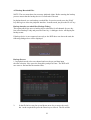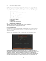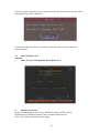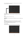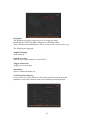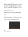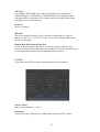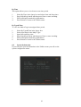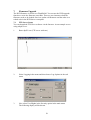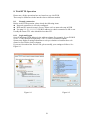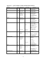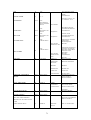
1
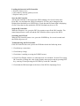
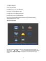
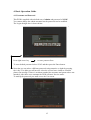
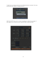
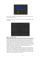
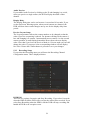
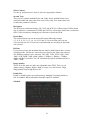
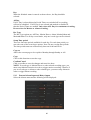
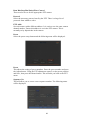
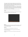
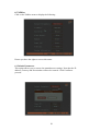
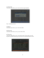
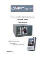
The new Alien Pod Digital Video Recorder
Operations Manual
Model DSD106
4 Channel Real Time DVR
Networkable
Mobile Phone Monitoring
Version 3.0
Table of Contents
Welcome
Important Safeguards and Warnings
1. Features
Local functions
2. Installation
2.1 Checking the DVR and its Accessories
2.2 HDD Installation
2.3 Rear Panel Description
2.3.1 DSD106
2.3.2 External Alarm In/Out & RS485 connections
3. Operational Instructions
3.1 Front Panel
3.2 IR Controller
3.3 Menu Description
3.3.1 Menu Items
3.3.2 Menu Operation
4. Basic Operation Guide
4.1 Username and Password
4.2 PTZ Control
4.3 Manual Record
4.4 Playback
4.5 Backup Recorded Files
4.6 Shutdown DVR
5. Parameter Setup Guide
5.1 Administrator and Password
5.2 Add and Delete User
5.3 Device ID
5.4 Video Output Standard
5.5 OSD Setup
5.6 Camera Input Adjustment –Camera Settings
5.7 Camera Input Adjustment –Mask Area Setup
5.8 View Tampering Alarm
5.9 Video Loss Alarm
5.10 Motion Detection Alarm
5.11 Preview Properties
5.12 Recording Setup
5.13 External Alarm Input and Relay Output
2
Page
4
4
5
5
6
6
6
7
7
8
9
9
11
13
13
14
15
15
17
19
20
22
24
25
25
26
29
30
30
32
32
33
34
35
37
38
40
5.14 Network Parameters
5.15 PTZ
6. Utilities
6.1 Default Parameters
6.2 Firmware
6.3 Hard Disk
6.4 Alarm Out
6.5 Reboot
6.6 Power Off
6.7 View Log
6.8 System Information
7. Firmware Upgrade
7.1 FTP Server Setup
7.2 Upgrade Mode
8. Web HTTP Operation
8.1 Network Connection
8.1.1 Login and Logout
9. Networking a Digital Video Recorder
9.1 Configure the DVR to operate with a modem router
9.2 For Beginners
9.2.1 How do I set my PC to obtain an IP address
automatically?
9.2.2 How do I set my PC’s IP address Manually?
9.2.3 How do I find out my PC’s IP address?
9.2.4 How do I use Ping to test a Connection to my
DVR?
9.2.5 How do I configure a Router for Remote
Access?
9.2.6 How do I find the On-Line Support?
9.3 Option 1: Connect a DVR directly to a single PC
9.4 Option 2: Connect a DVR to a switch or hub
9.5 Option 3: Connecting for Internet Access
9.6 Network Cable Connections
Appendix A Hard Disk Capacity Information
Appendix B Recording Timetable
Appendix C Quick Help Guide
Appendix D Specifications
3
45
47
50
50
51
52
53
53
53
53
55
56
56
58
59
59
59
60
60
61
62
62
62
62
63
63
64
65
66
67
68
69
70
72
Welcome
This operating manual is designed to be a reference tool for the installation and
operation of your system.
Here you can find information about this series DVR features and functions, as well
as a detailed menu tree.
Before installation and operation please read the following safeguards and warnings
carefully!
Important Safeguards and Warnings
1 Electrical Safety
The installation and operation should conform to local electrical safety codes.
2 Transportation Security
Avoid placing equipment on top of this DVR and do not subject the unit to strong
vibration or water during transportation, storage and installation.
3 Installation
Always install the unit in an upright position. Handle with due care.
Do not apply power to the DVR before completing the installation.
Do not place objects on the DVR or restrict air flow to this DVR.
4 Qualified Engineers Needed
Only entrust examination and repair work by qualified service engineers.
We are not liable for any problems caused by unauthorised modifications or attempted
repair.
5 Environment
The DVR should be installed in a cool, dry place away from direct sunlight,
inflammable, explosive substances etc.
Note: Note that the manufacturer of this product reserves the right to make
modifications to the DVR and/or these instructions without prior notice.
4
1 Features
This DVR range uses the embedded MCU and realtime operating system
combining the most advanced technology in the information industry. It incorporates
video and audio encoding and decoding, hard disk record and TCP/IP. The firmware
is installed in the flash drive and is very stable and reliable.
The DVR has both the features of a digital video recorder and a digital video
server. It works as a standalone unit or can be incorporated into a powerful surveillance
network, suitable for use in shops, transportation, warehouses, clubs and public houses etc.,
and particularly where space is limited.
Compression
Supports CIF mode at 25FPS, 2CIF at 12FPS and 4CIF at 6FPS, multi area motion
detection, OSD and changeable OSD position, LOGO and changeable LOGO position.
Local functions
Record
Supports multiple record type, including realtime, manual record, motion detection,
external alarm, motion&alarm, motion/alarm. Allows selection of CIF mode at 25FPS,
2CIF at 12FPS and 4CIF at 6FPS.
Supports 1 SATA Hard Drive, FAT32 file system, HDD SMART technology, cycle
or non cycle record, backup of recorded files and clips.
Supports USB memory, USB HDD, USB CD-R/W and USB DVD-R/W.
Preview and Playback
Supports internal composite monitor or VGA output and composite spot monitor. Internal
or VGA monitor provides multiple preview modes, sensitive area mask, camera alarm
block, single channel playback by file or time and displays local record status. Spot
provides single channel preview mode only.
PTZ
Supports numerous PTZ protocols, presets, sequence and cruise.
Alarms
Supports exception alarm, motion detection alarm, external alarm etc.
Others
Supports IR control and multi-level user management.
Network
Supports TCP, UDP, RTP, Multicast for network preview and PPPoE for broadband.
Supports remote parameter setup, can send alarm information to remote centre,
network control PTZ, network record live stream, network download and play back
recorded files in DVR and remotely upgrade firmware.
5
2. Installation
2.1 Checking the DVR and its Accessories
When you receive the product, check that all the items are included in your package.
2.2 HDD Installation
The DVR is not fitted with a Hard Drive unless purchased separately. The size of
the Hard Drive can be calculated according to the total capacity required. A table is
supplied at the end of this manual.
.
This DVR uses one SATA Hard Drive up to a maximum of 1 Tb.
First remove DVR case top.
Fit hard drive to base plate with screws.
Connect SATA data cable correctly and then power cable. Ensure cables are fitted
tightly.
Refit DVR case top and power up unit.
Ensure HDD is formatted before use. Details can be found in this manual.
6
2.3
Rear Panel Description
2.3.1 DSD106
This section provides information about the rear panel. When you install this series
DVR for the first time, please refer to this part first.
10
1
2
No.
3
4
5
Function
6
7
8
9
Description
1
USB Port
Port not functional
2
Video Inputs
4 Channels standard BNC
3
Video Outputs
No. 1 Main Video BNC Out ~ No. 2 Spot Video BNC Out
4
Audio Input
1 Channel RCA (1.0v p ~ p, 75 ohm)
5
Audio Output
1 Channel RCA (1.0v p ~ p, 75 ohm)
6
LAN Interface
Network Connection
7
VGA Interface
8
Alarm/RS485
VGA Display
RS485 connections for PTZ, 4 input alarms and 1 output alarm
See below for more detail.
9
12vDC Input
Connection for Power Supply Unit 12vDC
10
Power Switch
Switch power on or off.
7
External Alarm In/Out Connection and RS485 connections
RS485 Connect telemetry
RS485 from PTZ to
transmit terminals T+ and
T-.
If using a keypad and this
DVR, connect keypad to
terminals T+ and T-.
Note: Do not set motion
detect in DVR for any
PTZ channel.
1 2 3 4 G G
4 x Alarm Inputs. G (GND)
This DVR has 4 alarm inputs with two connections for ground and one output alarm.
Note that if you remove the alarm input terminal connection block, the connections are
detailed on the DVR case.
The RS485 connections for controlling up to 4 x PTZ cameras must be connected to the T+
and T- terminal block as shown above.
1 x Alarm Output Connection
Please note the usage of jumper JJ1. If you use DC, either connection is okay. It is
suggested that you use 12vDC at less than 1 Amp. If you use AC, ensure the jumper is
opened. There is a jumper on the mainboard corresponding with the alarm output. The
default is closed.
WARNING: IF YOU USE AC FOR RELAY OUTPUT, ENSURE THE JUMPER IS
OPENED.
8
3. Operational Instructions
3.1 Front Panel
3
2
6
1
2
5
4
TFT Screen
9
POWER
HDD
TxRx
6
NOTE: SHIFT button is used to switch between numeric keys and function keys
10
11
Loading the batteries in IR Controller
1. Remove battery cover.
2. Insert battery ensuring polarity correct.
3. Replace battery cover.
Start the IR Controller
Aim the IR Controller at the front of the DVR standing a few feet from the unit.
Press DEV key and input the DVR I.D (default is 255 but can be changed in the
Display Menu and then press ENTER key. Check that the IR Status light is displaying
Green). Note that in some models the DVR I.D default may be set to 88.
Stop the IR Controller
When the IR status is on, press the DEV key again to turn off the IR Controller. The
status lamp will now switch off and the IR Controller will not operate the DVR.
Switching the DVR off
When the IR Controller status is on, press the POWER key for several seconds and
the DVR will power off.
Troubleshooting the IR Controller
If the IR Controller does not operate the DVR then check the following items:
1. Check battery connections
2. Check battery charge
3. Check there is nothing covering the DVR IR sensor.
4. Check I.D in Display menu to see what has been set as default. Use this I.D to setup
IR Controller or change the value in the Display menu and use that by pressing DEV
key, entering I.D and pressing the ENTER key on the IR Controller.
5. Check that the IR Status light on the front of the DVR is displaying Green.
12
13
3.3.2 Menu Operation
How to enter menu mode
Press MENU key to enter DVR Main menu
Press PLAY key to enter Playback menu
Press REC key to enter Manual Record menu
Press PTZ key to enter PTZ control interface.
Special Note: You must input username and password. The default username is
admin and the password is 12345.
Main Menu Description
The small rectangular frame allows the user to move to the required menu option. To
move, use the
or
keys on the Control Key Direction Unit (CKDU).
When you have selected the required icon press Enter (this is the center key on the
CKDU).
14
4. Basic Operation Guide
4.1 Username and Password
This DVR is supplied with a default user of admin and password of 12345
You cannot change the admin username but the password can be modified.
The Login dialogue box is shown below:
Press right arrow key
to enter password box.
To enter default password select 12345 and then press the Enter button.
Note that you can select a different password using numerics or alpha by pressing
the A key. For alpha you will need to select the correct letter similar to a mobile
phone text message. If there is an alarm sounded the username and password are not
matched. After three error attempts the DVR will enter Preview mode.
To modify the password you must access the User menu.
15
To add a new user and password press the Add button and enter username. Now enter
the Password and verify by re-entering password.
SPECIAL NOTE: Please refer to section 5 regarding the setting of access rights. If
these rights are not set then new users will not be able to operate this DVR.
16
4.2 PTZ Control
In preview mode press PTZ key and in login mode select username and password.
You can now enter the PTZ control interface. Note that the user must have the PTZ
control rights set.
In menu mode press the PTZ menu..
There is a PTZ Control prompt in the PTZ control interface. The displayed camera
name details the name of the camera you are controlling.
Select Channel
In PTZ control mode you can press the numeric keys to select a channel. If DVR has
less than 10 channels, press one numeric key to select. For example to select camera
2 press the 2 key. If the DVR has 10 or more channels you must press two numeric
keys to select channel number. For example for camera 2 you must select keys 0 and
2 simultaneously and for camera 12, select numeric keys 1 and 2.
PTZ Control Keys
Direction keys
Zoom keys
Focus keys
Iris keys
Adjust Preset keys
Auto Control key
Wiper Control key
Light Control key
Auxiliary Control
ZOOM+
ZOOMFOCUS+
FOCUSIRIS+
IRISREC/SHOT
PLAY/AUTO
WIPER/MENU
LIGHT/F1
AUX/F2
17
Adjust Preset Number
In PTZ control mode, press the REC/SHOT key, and then press the preset number
(three numeric keys) and the relevant preset can be selected. Press REC/SHOT key
again and change the preset number. When you exit PTZ control mode, the camera
will stay at the current position.
Note: The PTZ preset number is set already. Please refer to PTZ menu for preset setup
instructions. Firmware version 1.4 upwards can support up to 28 presets.
Start/Stop auto in PTZ control mode
In PTZ control mode press PLAY/AUTO key to start PTZ auto function. Press
PLAY/AUTO key again to stop. When PTZ is in auto mode and you exit this mode
the PTZ will continue to auto function. You must enter the PTZ control mode again
and press the PLAY/AUTO key to stop.
Exit PTZ control mode
Press ESC or ENTER to exit and return to preview mode.
18
4.3 Manual Record
The user must have the corresponding rights to use this facility. In preview mode
press the REC key and enter the username and password to enter the Manual Record
interface. In menu mode press the REC key to enter Manual Record directly.
Channel:
Lists the channel numbers available on this DVR
Status:
Channel status has four modes
X
=
idle
Green =
channel recording (schedule, motion or alarm)
Red =
network transmission
Orange =
recording and network transmission
Start/Stop
ü
X
Start All
Press this button to start all channels recording
Stop All
Press this button to stop all channels recording
=
=
start corresponding channel recording
stop corresponding channel recording
Exit Manual Record
Press ESC key to enter preview mode. Press MENU key to enter main menu.
Press PLAY to enter playback menu. Press PTZ key to enter PTZ control mode.
19
4.4 Playback
The user must have playback rights. In preview mode press the PLAY key, select
username and password to enter playback interface. In menu mode press the PLAY
key and enter playback interface directly.
Note that this DVR only supports one channel playback.
Chan:
Use
or
keys to select one channel.
Rec. Type:
Use or
keys to select recorded files. There are 5 file types that
can be selected:
All
=
All files
All Time
=
All schedule recordings
Motion Detect =
Motion detection files
Alarm
=
Alarm recorded files
Manual
=
Manually recorded files
Time:
Enter the “From and To”date and time selected
Search:
Search the matched recorded files and display them in list box. If no
files are found a corresponding dialogue box is displayed.
Play by Time:Playback the recorded channel based on time section.
Select Page: In the file list box, only 8 files are displayed per page. If the selection
covers more than 8 files these can be seen by selecting further pages. Up to 500 pages
containing a maximum of 4000 files can be searched at one time. Use the numeric
keys or the up and down arrow buttons to selected the required page.
File List Box: This lists the matched files. File start time and file size are displayed.
Use the up and down arrow keys to move the scroll bar to select file.
20
Backup Devices:
You can select USB memory stick, USB HDD or USB CD-R/W
to backup files.
Copy:
Backup Today:
Starts backup
Backup all recorded files from today.
There are two kinds of playback mode. Search and playback file, and playback by
time.
Search and playback file: In the playback interface you can select only one
channel playback but using the client software you can playback up to 4 channels.
Select channel, record type and time from and to. Now click on Search and the files
found for that period will be listed in the matched files list. If you click on one file
and then press the PLAY key the recorded file will play back. If the DVR cannot find
matched files a failure dialogue will be displayed.
1. Adjust play progress backwards or forwards
2. Adjust play speed. Normal = 1x. Decrease to 1/2x, 1/4x, 1/8x and
single frame. Increase to 2x, 4x, 8x and MAX.
3. Pause/continue. If setting single frame press Enter to display each frame.
4. Audio
5. Copy segment. Press EDIT to start copy.
6. Go backwards.
7. Select enlarged segment for viewing.
8. Press the ESC button to return to preview mode.
NOTE: When DVR is busy and you select high speed playback you may find
actual speed can be reduced.
21
4.5 Backup Recorded Files
NOTE: The user must have the necessary playback rights. Before starting the backup
process ensure that the backup device is connected to the unit.
In playback mode you can backup recorded files. In preview mode press the PLAY
key and log in to enter the playback interface. In menu mode just press the PLAY key.
Backup intraday recorded files (Backup Today)
This option allows the user to backup all recorded files for all channels for one day.
Just select Backup Today and press the Enter key. A dialogue device will display the
backup status.
If backup device is not connected correctly or the DVR does not detect the unit, the
following dialogue box will be displayed.
Backup Process
1. In playback mode select one channel and record type and then input
the time selection. Now press the Search key and press Enter. The DVR will
now start to find and list the matched files.
2.
In the file list box use the up and down arrow key to move the scroll
bar. At the required file press the Enter key to select it. The file will be
22
ticked. You can use the same method to select other files to backup.
When you have selected the files to backup go to the next step.
3.
At this point select the required backup device. You can select from
the following devices: USB memory stick or USB CD-R/W.
4.
Press the Save button and press the Enter key to start backup. When
backup starts the corresponding message box will indicate the result.
Backup video segment
An additional facility is available to backup parts of an incident. This may
be useful when there is a part of the recording not required. The following steps need
to be followed:
1. Start playback or select playback by time.
2. Press the Edit key to start selecting the current playback image and
press Edit again to stop selecting the segment required.
3. Repeat step 2 to select up to 30 segments maximum.
4. On completion of the selection of segments press the ESC key and a
dialogue box will be displayed. If you press the Confirm key the DVR
will start to backup the selected segments. If you press the Cancel
button the DVR will abort the backup.
23
4.6 Shutdown DVR
NOTE: Do not power off the unit by removing the mains supply as this may damage
the Hard Drive fitted. Always use the Power Off facility in the Utilities menu or press
the Power key on the front panel or on the I.R Controller.
Shutdown DVR normally
Using the Menu
Enter the Utilities menu and press Power Off button. Now enter dialogue box and
press Confirm to shutdown DVR.
Using the Power key on front of DVR or via the IR Controller
Press the Power button for 3 seconds. In preview mode a login dialogue box will be
displayed. Enter password and press Enter to display power off dialogue box. Now
press confirm to shutdown DVR. If you enter incorrect password three times the DVR
will return to preview mode.
In menu mode if the user has the Utilities rights, you can enter into power off
dialogue and press confirm to shutdown DVR. Otherwise the user cannot shutdown
the DVR. If the DVR is shutdown correctly the power light is illuminated red.
NOTE: When the Shutdown message appears, please do not press the Power key
again else the DVR will not shut down.
Shutdown DVR abnormally
If you power down the unit without going through the menu or via the Power key on
the machine, there is a chance that the hard drive could be damaged. When power is
lost through a power failure then this can happen so it is suggested that the unit is
connected to a UPS unit.
24
5.
Parameter Setup Guide
NOTE: Only users with Parameters Setup rights can access these menus. When the
following parameters are modified and saved you must reboot the DVR to make the
new parameters effective. Some parameters do not need a reboot. The following do:· Network parameters
· Stream type, resolution and record schedule
· External alarm sensor
· View tampering alarm schedule
· Video loss alarm schedule
· Motion Detection alarm schedule
· External alarm schedule
· Alarm output schedule
· Transaction
· Change video output standard
5.1
Administrator and Password
When the DVR leaves the factory there is one default administrator.
The username is admin and the password is 12345
Password Modification
Press the Menu key and login selecting the username admin. Use the right arrow key
and move cursor to password edit box. Input 12345 and press confirm to enter the
administrator menu.
Select the User menu and press Enter key to enter the User Management menu.
In the username list box you can see only admin exists. Use the right arrow key to
move to the password edit box and press EDIT to enter edit status. Press numeric keys
to input new password. The password must be a maximum of 16 numerals. After
entering password press Enter to exit. Click on Verify and enter password again. Now
press the Confirm button and press Enter. If password and verify password are the
25
same, the password will be saved. If password and verify password are not the same a
warning message will be displayed.
If this occurs then press Enter to return to password edit box and re-input new
password again.
5.2
Add and Delete user
Add user
1.
Enter the User Management menu. Refer to 5.1
2.
Add new username
In the User Management menu press Add button and press Enter and in
the dialogue box displayed input the new username and then press
Enter. Up to fifteen usernames can be input.
26
3.
Setup the password for a new user
When you add a new user the password field is blank. If you do not
want to change the password you can ignore this step.
In the users list box in the User Management menu, use the up and
down arrow keys to select the new username and then use the right
arrow key to enter the password edit box. Press Edit key to enter edit
box and use the numeric keys to input the new password.
4.
Setup the new user privileges
A new user has no operational rights. The rights or privileges must be
setup using the Set Rights menu.
In the list box in the User Management menu select the new username
using the up and down arrow keys and using the right arrow key select
the Default Privilege button and then press Enter. This sets up all the
27
rights appertaining to this username. These include local playback,
remote playback and log access etc. If you wish to reduce these rights
select the Set Privileges button. Use the left and right arrow keys to
move to the appropriate rights, then press Enter or Edit key to enable or
disable the facility. A tick confirms the right is enabled. On completion
of changes press the Enter button to save the new user rights and return
to the User Management menu. If you press the Cancel button the user
rights will be aborted.
5.
Saving the new username password and rights
In the User Management menu press the Confirm button and the user
password and rights will be saved and you will be returned to the Main
menu. If you press Cancel the user password and rights will be aborted.
User Rights Description
Local Rights
Local rights are for local operators such as using the DVR front panel, IR
remote and RS485 keyboard.
PTZ Control:
Local control of PTZ
Record:
Manual stop/start recording
Playback:
Local playback and backup of recorded files
Parameter Setup:
Local setup of DVR parameters
Log:
Locally view the DVR log
Utilities:
Locally upgrade firmware, format HDD, reboot DVR
and shutdown DVR etc.
Remote Rights
PTZ Control:
Record:
Playback:
Parameters Setup:
Log:
Utilities:
Voice:
Preview:
Alarm:
Local Video Out:
Remote control of PTZ
Remote manual start/stop recording
Remote playback, download the recorded DVR files
Remotely setup DVR parameters
Remotely view the DVR log
Remotely upgrade firmware, format HDD, reboot DVR
and shutdown DVR
Client talks through DVR
Network live preview
Remote control DVR alarm output
Remotely control DVR video output
MAC address
The MAC address is not the address of the DVR but the PC that accesses the
DVR. If you setup this MAC address only the PC with this MAC address can
access this DVR.
Local Play
Administrator can set local playback rights option for each channel.
Remote Play
Administrator can set remote playback rights option for each channel.
28
Remote Watch
Administrator can set remote preview rights for each channel.
Delete User
In the User Management menu you can use the up and down arrows to select
one user, then use the right arrow key to select the DEL button. If you then
press the Enter button a confirmation dialogue box is displayed and pressing
the Confirm button deletes the selected user. Pressing Cancel or ESC will
abort the delete.
5.3
Device ID
Select the display menu:
When you use the IR controller to operate the DVR you must use the device
ID to select the DVR. The default device ID is 255. If you are using more than
one of these DVRs then ensure each unit is allocated a different ID. In Display
menu move to the Device ID box and enter a device range 01 ~ 255. Press the
Confirm button to save or press Cancel to abort. Whatever ID you set, you will
need to enter this on your remote controller. Aim the remote at the DVR and
press the DEV key, enter the ID set in the Display menu and then press Enter
on the remote. The status led on the front of the DVR must turn to green.
29
5.4
Video Output Standard and VGA Setup
Video Output Standard
This DVR will support PAL or NTSC video output. Set the video output to
match the video input standard by selecting the Video Standard box with the
up and down arrow keys and selecting PAL or NTSC. PAL is the standard
used in the U.K.
VGA setup
There is one VGA interface on the rear of the DVR. Set the VGA resolution of
the monitor in the Display menu. Select from the following options:
1024 x 768 60Hz, 800 x 600 60Hz, 800 x 600 75Hz..
Use the up and down arrow buttons to select option and then press Confirm
button to save or press the Cancel button to abort.
5.5
OSD Setup
OSD (On Screen Display) allows the system time and camera name to be
displayed. OSD settings include: system time, time format, time display
position, camera name, camera name display position etc.
System Time
In the Display menu you can setup the DVR system date and time.
Display System Time
You can also display the properties of each camera including display status,
position and format. You can copy the properties from one camera to another.
In the Image Setup menu select one camera:
Date OSD
There are four display modes: Opaque&Steady, Transparent&Steady,
Transparent&Flashing and Opaque&Flashing. Move to Date OSD and select
one mode.
30
Display Position and format
Move to the Position button and press Enter to enter setup image. Here you
will find there are 22 x 18 small panes with the OSD position marked in red.
Use the arrow keys to move to the required OSD position.
Press Edit key to select OSD format
The following OSD formats are provided:
MM DD YYYY W hh:mm:ss (default)
MM DD YYYY hh:mm:ss
DD MM YYYY hh:mm:ss
YYYY MM DD W hh:mm:ss
YYYY MM DD hh:mm:ss
YYYY = Year, MM = month, W = weekday, hh = hour, mm = minutes,
ss = seconds
Press Enter to save and return to Image menu or press ESC to abort.
Copy parameters
After the setup properties of one camera has been completed you can copy the
same values to other cameras. Press the Copy to Camera box and enter the
required camera number.
Camera Name
In the Image menu you can set the name for each camera. Note that camera
names cannot be copied. The following steps cover setting the camera name:
1.
Select one camera
2.
Move to Name box and press Edit button and then input digital
numbers, uppercase or lowercase characters as detailed earlier.
The camera name can be 32 characters long maximum.
3.
Press Edit key to exit edit status. Select Confirm and press Enter to
save the change and you will now see the new camera name. Press
Cancel button or ESC key to abort.
NOTE: To change to Upper case, lower case, numerics or symbol press the A
button and then press 0 to scroll through characters required. Click on the
number appertaining to the character or symbol required.
Setup Camera Name Position
If you do not want to display camera name disable the check box beside
camera Name with an X. If you enable the check box you can setup the
camera name position. The steps are:
1.
2.
3.
Enter the Image Setup menu
Select one camera
Enable the check box on the side of the camera name and move to the
Position button. Now press Enter and using the arrow keys move
camera name position. When set, press Enter to fix position and return
to Image menu. Then press Confirm button to save. If Cancel or ESC
is pressed in the Image Setup menu the change will be cancelled.
31
5.6
Camera Input Adjustment –Camera settings
In order to set the camera and background light levels to provide the best
video images you need to set the video parameters such as brightness,
saturation, contrast and hue. If you select the Camera menu and then Colour
Setup you can set the brightness, saturation, contrast and hue settings. Press
the Confirm button to save the settings or press the Cancel button to abort.
5.7
Camera Input Adjustment - Mask Area Setup
In order to set the mask area setup, select the Camera menu and then
Advanced Settings. Privacy masking allows a camera view to be edited so that
unwanted video areas captured are ignored.
The following menu is displayed:
If you select the Privacy Mask option marked X it will be activated and you
can then select the Area setting.
32
The following screen is displayed:
Move the yellow square using the mouse to where you wish to exclude video
capture. Now press the left mouse key and Edit button and use the arrow keys
to set the first area. Press Edit again to save the mask area. The maximum
mask area is 8 x 8 panes and the minimum size is one pane. Press Enter to
return to Advanced Settings and press Confirm to save the masks set. Press A
to clear all mask areas. The maximum mask areas are 4. The total mask areas
are displayed during setup.
5.8 View Tampering Alarm
This option is used to produce an alarm warning if the camera video is blocked.
Select Camera menu and Advanced settings and then select View Tampering
by clicking on up or down arrow buttons to the right of this. This will change
the Off display to either Low, Normal or High sensitivity and setup the Area
and Policy Boxes. The Area allows one box to be set similar to the Privacy
Masking option. Press Enter to return to the Advanced Settings box and then
click on Confirm. If you click on the Policy button you can enter the View
Tampering Handle menu.
This allows the user to set up to four periods per day for one week The DVR
will react only as per schedule set. You can copy one days settings as another
day. Do not overlap time periods and reboot DVR to make effective.
33
Setup Alarm Policy
The DVR will react to the Policy set. You can select one or more options from
the following: On Screen Warning, Audible warning, Upload to Center and
Trigger Alarm Output. Use the mouse to change the cross to a tick. Ensure the
Confirm button is pressed to save the settings. Pressing ESC will abort the
setting. Any changes made to the parameters must be followed by a reboot.
5.9 Video Loss Alarm
If the video camera or cable develops a fault causing video loss the DVR can
be set to detect this
Enter the Camera menu and select Advanced Settings. Now click on the
Ignore button to the right of Signal Loss. By clicking the up or down arrow in
the box the Ignore will change to Handle. This then displays the Policy box.
If Policy is clicked on then the Video Signal Loss Handle is displayed.
The DVR will react to the Policy set. You can select one or more options from
the following: On Screen Warning, Audible warning, Upload to Center and
Trigger Alarm Output. Use the mouse to change the cross to a tick. Ensure the
Confirm button is pressed to save the settings. Pressing ESC will abort the
setting. Any changes made to the parameters must be followed by a reboot.
34
5.10 Motion Detection Alarm
This function provides an alarm when motion detection is triggered.
Select the Camera menu and the above menu is displayed. Select Motion Det.
Level which is the motion detect sensitivity. There are seven options. 0 is the
lowest to 5 the highest and Off. If you leave option set to Off there will be no
DVR response. If you select 0 ~ 5 this will activate Motion Area Setup and
Policy Setup. If you select 0 for low sensitivity the DVR will only respond to
major motion changes. If you set sensitivity to high at the 5 end, only small
motion changes will set off the motion detection.
Motion Area Setup
You must define the motion areas so the DVR can respond when there is
motion in the area set. In the above menu click on Motion Det. Level Area
button. The screen is divided into 22 x 18 squares with a yellow square where
the cursor from the mouse is placed. This menu allows the whole area to be
detected by pressing the PTZ key. If you press the A button you will clear all
motion areas. You can setup multi areas by using the right or down direction
keys to set an area and then pressing the Edit key will allow the next area to be
set. Press Enter to save changes and return to previous menu.
The keys to set the motion function are as follows:
Direction Keys:
Edit:
Arrow Right:
Arrow Left:
Arrow Down:
Arrow Up:
PTZ:
A:
Enter:
ESC:
Moves yellow square to first motion start position
Switches from yellow to black to set first position
Increases motion boxes to the right
Reduces motion boxes to the left
Increases motion boxes down
Reduces motion boxes up
Sets whole screen to black for all motion detection
Clear all motion boxes and changes screen to blue.
Save and return to previous menu.
Cancel setup and return to previous menu.
35
The outer area has been set for motion detection. The centre blue box is the
non-detectable motion area.
If you click on the Motion Det. Level Policy the Motion Alarm Handle menu
is displayed:
Motion Alarm Recording
When motion detection is activated you need to set the record channels in the
Motion Alarm Handle menu. If you click on the channels you can change the
X settings to ticks. Note that to start the cameras recording you must enable
the Recording Schedule and set Motion Detection or Motion/Alarm. This is
further explained in Recording Setup. The DVR will react to the Policy set.
You can select one or more options from the following: On Screen Warning,
Audible warning, Upload to Center and Trigger Alarm Output. Use the mouse
to change the cross to a tick. Ensure the Confirm button is pressed to save the
settings. Pressing ESC will abort the setting. Any changes made to the
parameters must be followed by a reboot.
If On Screen Warning is enabled and DVR is in preview mode, the relevant
camera image will be displayed. If more than one camera is enabled, and they
are all triggered, the DVR will automatically display the camera images one
by one for a 10 second period per camera until the motion ceases. The DVR
will then revert to preview mode. To disable motion alarm area and/or alarm
policy, just set motion alarm sensitivity to Off.
36
5.11 Preview Properties
In the preview menu you can setup preview mode, screen switch time, enable
or disable audio preview and preview layout.
Now click on Preview Setup and enter the Preview menu shown below.
Preview Mode
If you click on Preview Mode you can switch between a single channel
display and four/eight/sixteen channel display. (Dependent on model)
Preview Switch Time
This is the Image Preview switch time. You can select between 5 seconds, 10,
20, 30, 60, 120, 300 and Never. If Never is selected the preview image is not
switched automatically.
37
Audio Preview
If you enable Audio Preview by clicking on the X and changing it to a tick,
when you preview a single camera, the DVR will play the audio of that
channel.
Display Delay
The Display Delay time can be set between 1 second and 10 seconds. If you
set the On Screen Warning option, when several cameras are alarmed, the
DVR will show these camera images one by one for the display delay time
period.
Preview Layout Setup
The Layout parameter allows the camera numbers to be changed so that the
order of preview sequencing is altered. For instance clicking on the camera 1
box and changing it to camera 2 automatically moves camera 1 to the second
camera position. A small display beneath the boxes shows the new display
order. Note that if you leave the Preview Mode in 1 Screen mode you can still
change the order. If you press 0 the corresponding window will not display
live video. Ensure the Confirm button is pressed to save your changes.
5.12 Recording Setup
If you select the Recording menu you will enter the Recording Channel
Configuration menu. This is displayed below:
If HD Full
There are two options Overwrite and Stop Recording. If you select Overwrite
when the HDD is full the DVR will overwrite the earliest files recorded. If you
select Stop Recording when the HDD is full the DVR will stop recording and
handle the DVR as an exception event.
38
Select Camera
Use the up and down arrow keys to select the appropriate channel.
Stream Type
There are two options Audio&Video and Video. Select Audio&Video if you
want both audio and video otherwise select Video only. You must reboot unit
to make this parameter effective.
Resolution
The DVR uses resolution settings, CIF, 2CIF and 4CIF (D1). When using 2CIF the frame
rate is reduced to a maximum of 12FPS and if 4CIF is selected the frame rate is reduced to
6FPS. If the resolution is changed you will need to reboot the DVR.
Frame Rate
The required frame rate can be selected from the following settings:
1, 2, 4, 6, 8, 10, 12, 15, 16, 18, 20, 22 and 25. For low frame rate you can
select low bit rate size. The bit rate is automatically set according to the frame
rate selected.
Bit Rate
If you select bit rate, the maximum bit rate must be limited when there are data
recording peaks. The bit rate is therefore associated to the frame rate selected.
The following options can be selected: 32K, 64K, 128K, 192K, 256K, 320K,
384K, 512K, 640K, 768K, 896K, 1Mbps, 1.25Mbps, 1.5Mbps, 1.75Mbps,
2Mbps and By User define. For CIF resolution the typical maximum bit rate is
384K ~ 768K.
Image Quality
This is set in the software and is not adjustable in the DVR. There are six
quality settings: Highest, Higher, High, Average, Low and Lowest. High
image quality needs a high bit rate size.
Enable Rec
Enable or disable camera record function by changing X meaning disable to
tick for enabled. When enabled the Schedule option is available.
Schedule
39
Day
When the Schedule menu is entered as shown above, the Day should be
selected.
All Day
If ALL Day is selected then the Period Times are switched off as recording
will not be scheduled . If ALL Day is not selected and marked as disabled X,
then the Period Times are enabled. Only select ALL Day for continuous recording.
Do not select for Motion or Alarm recording.
Rec Type
The Rec Type options are All Time, Motion Detect, Alarm, Motion|Alarm and
Motion&Alarm. For all day record mode, only one record type can be selected.
Setup Time period
There are four time periods available for each day. For each time period you
can select one of the record type options. Note: Do not overlap time periods.
The time periods must run consecutively between 00:00 and 24:00.
Copy to:
Allows the current page to be copied to Monday through Sunday or All.
Copy
Click on this function to start the copy.
Confirm/Cancel
Click on confirm to save the changes and cancel to abort.
NOTE: If record type is Motion Detect or other related recording types, you
must setup Motion Detection in order to trigger motion recording. Likewise if
you set record type as Alarm or other related types, you must setup Alarms in
order to trigger alarm recording.
5.13 External Alarm Input and Relay Output
Select the Alarms menu and the following will be displayed:
40
Select Alarm In
Click on this function to select alarm 1 through 4.
Alarm Type
Select N.O (normally open) or N.C (normally closed)
Alarm Handling
Select Handle or Ignore. Handle will display the Policy and PTZ Linkage
options.
Policy
Select Policy and the Alarm in Handling menu will be displayed as follows:
Record Camera
Select the camera channels to record by clicking on the camera numbers
changing the X disable to enabled ticked.
AlarmIn Schedule Day
Select the day Monday through Sunday.
Periods
You can setup up to 4 periods within each day.
Note: Do not overlap time periods.
The time periods must run consecutively between 00:00 and 24:00.
Copy to:
Allows the current page to be copied to Monday through Sunday or All.
Copy
Click on this function to start the copy.
Alarm Handle Method
You can select one or more handle method. They are: On Screen Warning,
Audible Warning, Upload to Center and Trigger Alarm Output.
41
If On Screen Warning is selected and an alarm is triggered and DVR is in
preview mode, the DVR will display an image of the related camera. If more
than one camera is triggered, the DVR will display them one by one every 10
seconds. When the alarm ceases the DVR will restore the preview mode.
Save setup
In the Alarm in Handling menu press Confirm button to return to the Alarms
menu and then in the Alarms menu press Confirm to save the changes.
PTZ Linkage in Alarms menu
This function allows the alarm to trigger PTZ links. If PTZ Linkage is clicked
on, the following menu is displayed:
The user must ensure that the PTZ used has the following functionality to
enable these options to be used.
Select Camera
First select the PTZ camera number. Use the up and down keys to select the
channel required.
Enable Preset
Click on the Enable Preset box to switch the disable X to enable ticked.
Preset
Input a preset number that has already been set in the PTZ camera.
Enable Sequence
Click on the Enable Sequence box to switch the disable X to enable ticked.
Sequence No:
Input a sequence number that has already been created in the PTZ camera.
This is the tour/patrol/cruise sequence number.
42
Press Confirm button to save and return to Alarms menu. Press Cancel or ESC
to abort to return to Alarms menu.
Copy to Alarm In
You can copy contents of this alarm settings to other channels. Select the
channel.
Copy
Click on this option to start the above copy.
Alarm Out
This DVR provides one alarm output for the DSD105 and four for the DSD108 and
DSD116.
Time
Select Delay Time. This is the time the relay will continue to be set after the
alarm finishes triggering. Select from 5seconds, 10sec, 30sec, 1 minute, 2
mins, 5mins, 10minutes and Manual. If you set Manual the alarm will not stop
until you confirm Alarm Stop in the Utilities menu.
Alarm Out Time
If you select the Schedule option the following menu will be displayed:
43
This menu allows you to set the alarm out schedule times.
Day
Select the day of the week for the alarm output
Start Time/End Time
You can select four periods in any one day. Do not overlap times and set times
consecutively.
Copy to:
Select other days you want to set the alarm out or all.
Copy
This allows the copy to be started.
Confirm
When you finish the setup press the Confirm button to save all parameters.
NOTE: If any schedule is modified you must reboot the DVR to make it
effective.
Copy to Alarm Out
This DVR only provides one output alarm. Therefore this and the Copy
options are not changeable.
Exceptions
Select the Exceptions menu and the following will be displayed:
44
Exceptions
The following exception events can be set to trigger an alarm:
HardDiskFull, NTSC/PALDiffer, IllegalAccess, IPAddrConflict,
NetworkFailure and HardDiskError. These events can be viewed on the Log.
The following are triggered:
Audible Warning
DVR will beep.
Upload to Center
Send exception information to center host P.C
Trigger Alarm Out
Trigger local relay output
AlarmOut1
Select to enable the alarm out.
5.14 Network Parameters
If you want to access the DVR via a network you must set up the network
parameters. Select the Network menu as the following will be displayed:
45
IP
Set the IP address in the DVR. The IP set by the manufacturer must be
changed. Refer to the later section on setting up a network. If there is a DHCP
server in the network you can set the IP as 0.0.0.0 then Confirm and the unit
will automatically reboot using DHCP to dynamically assign an IP address,
Mask and Gateway. If you then go into the Network menu, you can see the IP
address allocated and then use this address for accessing by the local client
software. If the unit still shows the IP address for the DVR as 0.0.0.0 then the
DHCP server has not been found and the IP address, Mask and Gateway will
have to be set manually.
Port
The port address for the Client software.
Mask
The subnet mask used. This must be common in all equipment used on this
network. This defines the size of the network and is generally 255.255.255.0
Gateway
The modem/router local address.
HTTP Port
This is set as 80 for access via Internet Explorer. This is for web access and
uses ActiveX to load the software. If ActiveX security does not allow the load,
then the security will have to be reduced.
Advanced Settings
If you click on Advanced Settings Setup the following screen will be
displayed:
Mac:
This is the DVR Mac address.
46
NIC Type
The default is 10M/100M Auto. Other options that can be selected are:
10M Half-Duplex, 10M Full-Dup, 100M Half-Duplex and 100M Full-Dup.
Half duplex allows send and receive serially whereas full duplex allows both
send and receive at the same time.
IP Server
IP Server address.
MCastIP
This is the multicast function. This is used for broadcasting to a range of
addresses (224.0.0.0 ~ 239.255.255.255). If you are not using multicast then
do not set this option.
Remote Host IP & Remote Host Port
If you set this IP and port when there is an alarm and an exception event
occurs, the DVR will send information to that host IP. The site with this IP can
receive alarm and exception event information from the DVR.
5.15 PTZ
If you click on the PTZ menu the following menu will be displayed:
Select Camera
Select camera channel 1 ~ 4/8/16.
Baud Rate
Set from the range of baud rates available that matches the PTZ camera.
47
Data Bits/Stop Bits/Parity/Flow Control
These need to be set for the appropriate PTZ camera.
Protocol
Select the necessary protocol used by the PTZ. There is a large list of
protocols from which to select.
PTZ Addr
Set each camera with a different address. It is easier to use the same camera
channel number. Ensure this address is set in the PTZ camera. This is
normally set by dipswitches in the camera.
Preset
Select the preset setup button and the following menu will be displayed:
Preset
This allows the setting of preset numbers. Enter the preset number and press
the Adjust button. Using the PTZ adjustment control, set the preset position
and Save, then press the Return button. This will take you back to the PTZ
menu.
Sequence No:
This will allow you to create a tour sequence number. The following menu
will be displayed:
48
The sequence number will consist of a maximum of 16 presets. Each tour or
cruise will have to be given a different sequence number. Each preset can be
allocated a dwell speed and dwell time. The dwell time is the time the presets
waits before starting a move to the next preset. The dwell speed is the speed
taken to move from a preset to the next preset.
Press the add button to add the presets in this sequence. When all details have
been entered press Confirm to save the sequence. To test sequence press the
StartSeq button and if running okay press the Stop button. This menu allows
you to delete presets. After completing setup press Return to go back to PTZ
menu then press Confirm to save all changes.
NOTE: This option will only work on PTZ units that have the features
available.
Returning to the PTZ menu the following menu is displayed when clicking on
Cruise Setup. This function is used to setup a pattern.
RecCru
Press the RecCru button and you will enter the PTZ control interface. Control
the PTZ using the keys and press the Enter button to save the pattern and
return to the Set Cruise menu.
StartCru
This will allow you to check the pattern so press Stop to end.
Press Return button to return to PTZ menu and in the PTZ menu press
Confirm to save the pattern.
NOTE: This option will only work on a PTZ that has the pattern function
Available.
49
6. Utilities
Click on the Utilities menu to display the following:
Ensure you have the rights to access this menu.
6.1 Default Parameters
This option allows you to restore the manufacturers settings. Note that the IP
address, Gateway and Port number will not be restored. Click Confirm to
proceed.
50
6.2 Firmware
You can use this option to upgrade the system firmware. Please read section 7
before progressing.
You can select one of two methods to upgrade the firmware. Select either
FTP or USB. If you select FTP mode you will enter the FTP Upgrade menu.
Input the FTP server IP address and then press Enter. The DVR will connect
via the FTP server network and download the firmware file. If you select the
USB mode, make sure you connect a USB memory stick containing the
firmware file in the root directory before selecting this option.
After the firmware upgrade completed reboot the DVR to start using the new
firmware.
SPECIAL WARNING
Applying the wrong firmware or not correctly completing a firmware upgrade
can leave the unit in an unusable state. If this occurs the mainboard may have
to be shipped back to the manufacturers or replaced and this is not covered
under the manufacturer’s warranty.
51
6.3 Hard Disk
This menu provides information about the hard drives. This includes capacity,
free space, standby or not and whether the status is normal or not.
Format
You must stop all recording before formatting the drives. After formatting you
must reboot the DVR otherwise it will not perform correctly.
Enter Confirm to complete the format.
52
6.4 Alarm Out
This menu option allows you to clear the alarm output manually.
Enter Confirm to proceed.
6.5 Reboot
This menu option allows you to reboot the DVR.
6.6 Power Off
This menu option allows you to power off the DVR.
6.7 View Log
This menu option allows you to view the Log menu. If you wish to view the
log based on default option just press the Enter key and all information will be
53
Alternatively you can search options by the following:
By Type, By Time or By Type&Time
By Type
This option displays log information according to the assigned type.
The type is divided into either Major Type or Minor Type. Major Type
includes Operation, Alarm, Exception and All. Each Major Type includes a
number of Minor Types, so you can select either a Major Type or a subset
within a Major Type classed as a Minor Type.
Operation
This includes the following minor types:
Power On, Shut Down, Abnormal Shut, Panel Login, Panel Logout, Panel
Config, Panel File Play, Panel Time Play, Local Start Record, Local Stop
Record, Panel PTZ, Panel Preview, Panel Set Time, Local Upgrade, Net Login,
Net Logout, Net Start Record, Net Start Transparent Channel, Net Stop
Transparent Channel, Net Get Parameter, Net Config, Net Get Status, Net
Alert On, Net Alert Off, Net Reboot, BiComStart (Start Voice Talk), Net
Upgrade, Net File Play, Net Time Play, Net PTZ.
Alarm
This includes the following minor types:
External Alarm In, External Alarm Out, Motion Detect Start, Motion Detect
Stop, View Tamper Start, View Tamper Stop.
Exception
This includes the following minor types:
Video Signal Loss, Illegal Access, Hard Disk Error, Hard Disk Full, IP
Conflict, DCD Lost.
Example - Viewing the Alarm Log.
1.
At Query select By Type.
2.
For Major Type select Alarm and for Minor Type select one of the
following:
3.
External Alarm In, External Alarm Out, Motion Detect Start, Motion
Detect Stop, View Tamper Start, View Tamper Stop.
4.
Press the SearchLog button and then press Enter to start searching.
5.
When search is completed DVR will list all matched alarm information.
In the List box the following information is included:
Index, Occur Time, Major Type, Minor Type, Panel User, Net User,
Host Address, Para. Type, Channel No., HDD No., Alarm In and
Alarm Out. You can also select the MoreInfo option and page number
to show more information.
6.
Press Return button to return to the Utilities menu.
54
By Time
This option allows you to view between one time period.
1.
2.
3.
4.
Select By Time in the Query box and select Start and Stop times.
Press SearchLog button and then press Enter to start searching.
DVR will display matched log information.
Press Return to return to the Utilities menu.
By Type&Time
To view one kind of log in an assigned time period.
1.
2.
3.
4.
5.
6.
Select By Type&Time in the Query box.
Select Operation for the Major Type.
Input Start and Stop time.
Press SearchLog button and then press Enter to start searching.
DVR will display matched log information.
Press Return to return to the Utilities menu.
6.8
System Information
If you select the System Information in the Utilities menu you will see the
system configuration menu:
55
7.
Firmware Upgrade
The DVR firmware is stored on a Flash ROM. You can use the DVR upgrade
function to write the firmware onto flash. There are two instances when the
firmware needs to be loaded. One is to update old firmware and the other is to
reload code in the DVR due to corruption.
7.1
FTP Server Setup
You can download FTP server software via the Internet. As an example we are
using wftpd32.exe:
1.
Run wftpd32.exe (FTP server software)
2.
Select Logging in the menu and then choose Log Options in the sub
menu.
3.
Now select User/Rights in the Security option in the main menu.
The following display will be shown:
56
4.
Create a new user. Select New User and a dialogue box will be
displayed.
5.
Input a user name of target and click okay.
6.
In the Change Password box input password in the New Password field
and again in the Verify Password filed. Click OK to save and exit this
box. You will now return to the User / Rights Security Dialog box (see
3. above). In the User Name box enter target and in the Home
Directory box enter the path where the firmware file is placed. Then
press the Done button to exit.
7.
Next time you will not need to run the setup procedure again, just
double click and open the wftpd32.exe to upgrade the firmware.
57
7.2
Upgrade Mode
There are three methods for upgrading the DVR firmware. These are as
follows:
1.
You can use the client software to upgrade the firmware file. You do
not need to use the ftp server software. Please refer to the client software user
manual for detailed information.
2.
Use the FTP function of Upgrade sub-menu in the Utilities menu. You
need one host PC to run FTP server software and read firmware file
“digicap.hex”. Make sure that the PC and DVR are in the same subnet.
3.
Use the USB function of Upgrade sub-menu in the Utilities menu.
Make sure the firmware file “digicap.hex”is placed under the root directory of
the USB memory stick. For example if the memory stick shows as drive H in
the PC, the file must be seen as H:\digicap.hex.
58
8. Web HTTP Operation
Please note, all the operations here are based on our 4-ch DVR.
There may be differences in the interface due to different models.
8.1
Network connection
Before web HTTP operation, please check the following items:
l Network connection is correctly configured
l DVR and PC network setup is correct. Please refer to network setup in DVR
l Use ping ***.***.***.*** (* DVR IP address) to check connection is OK or not.
Usually the return TTL value should be less than 255.
8.1.1 Login and logout
Open IE and input DVR address in the address column. For example, if your DVR IP
is 10.1.27.200, then please input http:// 10.1.27.200 in IE address column.
System may display warning information to ask you whether to install webrec.cab
control or not. Please click yes button.
If you can’t download the ActiveX file, please modify your settings as follows. See
Figure 0-1.
Figure 0-1
Figure 0-2
59
9.
Networking a Digital Video Recorder
9.1
Configure the DVR to operate with a modem router.
For experienced Users
Configure the DVR as follows:
a.
It is assumed you have a PC working on Broadband Internet.
b.
Check IP address in P.C and record IP Address, Subnet Mask & Gateway
Address.
Example: IP Address 192.168.0.10 Subnet: 255.255.255.000
Gateway: 192.168.0.1
c.
Connect LAN cable from router to DVR.
d.
Assign DVR a private IP address Example : 192.168.0.20
You need to assign the DVR an IP address similar to PC. The IP address you
assign must be unique but the first three levels must match your local network.
When configuring the DVR’s IP address information, the version of firmware
within the units may display the IP addresses differently. For simplicity
192.168.0.20 may have to be configured as 192.168.000.020
1.
2
3.
4.
5.
6.
7.
8.
Enter the DVR Menu –Go to Network Settings
Enter Network menu
SET IP ADDRESS (see above), Subnet Mask: 255.255.255.000 (example),
GATEWAY 192.168.0.1 (example - Router local address), Service Port 8000,
HTTP Port 80, Protocol TCP and SAVE.
EXIT MENU.
Now turn Router off and on. This will take about one minute to reset.
Your DVR is now ready for access via the local PC using the Client Software.
Refer to your modem/router manual for instructions on how to configure it to
allow incoming Internet access.
If you fail to access DVR check all steps again.
60
9.2 For Beginners
You must be able to perform some basic tasks in order to connect your Digital Video
Recorder to a PC and subsequently the Internet.
The following page describes some simple tasks but more help is available online at
www.systemq.com so before you start please download the following tips from the
website ‘Online Support’section –
Tip 117
TIP 36
Tip 58
Describing how to set a PCs IP Address
Describing how to perform ‘ping’test
Describing how to configure a router for Internet access
The diagrams that follow suggest settings that if used will result in a successful
connection.
Bear in mind that when it comes to Option 3 for Internet use, different router
manufacturers may not use the exact settings given here so slight adjustments may be
necessary.
61
9.2.1 How do I set my PC to ‘Obtain an IP address automatically’?
· Control Panel,
· Network Connections,
· Local Area Connection,
· Properties,
· Internet Protocol (TCP/IP),
· Properties,
· Select ‘Obtain IP Address Automatically’
9.2.2 How do I set my PC’s IP Address Manually ?
· Control Panel,
· Network Connections,
· Local Area Connection,
· Properties,
· Internet Protocol (TCP/IP),
· Properties,
· Select ‘Use following IP Address’
· Enter … IP Address
Subnet mask
Default gateway
9.2.3 How do I find out my PC’s IP Address ?
· Start
· Run
· Cmd
· ipconfig
9.2.4 How do I use Ping to test a Connection to my DVR ?
· Start
· Run
· Cmd
· Ping <IP-Address> <Enter> eg: ping 192.168.0.20 <Enter>
62
9.2.5 How do I Configure a Router for Remote Access ?
· Instructions on the SystemQ website cover the NET800 and Netgear Routers
9.2.6 How do I find the On-Line Support ?
http://www.systemq.com/cgi-bin/commerce.exe?display=user2
Detailed descriptions are available there for all these questions plus more besides,
including …
·
·
·
·
·
·
How to find a device’s MAC address (Tip 3)
How to implement Dynamic DNS (Tip 56)
Setting Internet Explorer Security Settings to install an Active-X (Tip 94)
How to control a PTZ from a DVR
How to play back recordings from various DVRs
Links for downloading client software packages
63
9.3
Option 1: Connect a DVR directly to a single PC
Tasks :
· Configure network settings in DVR manually
· Configure network settings in PC manually
·
Connect DVR & PC together using an RJ45 cross over cable
· Install and configure the DVR client software
· Reboot both DVR & PC
· Test the PCs connection to the DVR using ‘Ping’
· Connect using the client software
64
9.4
Option 2: Connect a DVR to a switch or hub
Tasks :
· Configure network settings in DVR manually
· Configure network settings in PC manually
· Connect DVR & PC together using an RJ45 cross over cable
· Install and configure the DVR client software
· Reboot both DVR & PC
· Test the PCs connection to the DVR using ‘Ping’
· Connect using the client software
65
9.5
Option 3: Connecting for Internet Access
Important Notes :
If using a BT phone line you must use an ADSL modem router, if using a NTL or
cable phone service you must use an appropriate cable router.
Be aware that when connected to the internet, the router has two IP addresses: internal
and external. The internal address is seen by devices connecting to it’s Ethernet ports,
the external address represents it’s connection to the local exchange via the telephone
line.
You can only test an external Internet connection from a PC not connected locally to
the modem/router.
66
Tasks :
· Find out what the external IP address is, this is assigned by the customer’s
Internet Service Provider
· Find out : is this a fixed IP address, ie: “Static, or does it change, ie:
“Dynamic”?
· Configure network settings in the DVR manually
· Configure network settings in the PC to “Obtain IP Address Automatically”if
possible, if not, then configure manually
· Connect DVR & PC to the modem/router using patch cables
· Install and configure the DVR client software
· Reboot both DVR & PC
· Test the PCs connection to the DVR using ‘Ping’
· Use the client software to connect to the DVR from the local PC
· Ensure the PC has outbound Internet access
· Configure the modem router for inbound access using either “Port
Forwarding”, or “DMZ”
· Ask a colleague offsite to test Internet access by connecting to the router’s
external IP address
9.6
Network Cable Connections
If you are connecting the Alien to a modem/router, network hub or switch then
you must use a patch or LAN cable. If you are connecting direct between the DVR
and a PC then you must use a crossover cable. The patch cable connections are the
same at both ends but a crossover cable is wired so that there are no Ethernet
connections.
Patch/LAN Cable Connections
1.
White/Orange
2.
Orange
3.
White/Green
4.
Blue
5.
White/Blue
6.
Green
7.
White/Brown
8.
Brown
1.
2.
3.
4.
5.
6.
7.
8.
White/Orange
Orange
White/Green
Blue
White/Blue
Green
White/Brown
Brown
Crossover Cable Connections
1.
White/Orange
2.
Orange
3.
White/Green
4.
Blue
5.
White/Blue
6.
Green
7.
White/Brown
8.
Brown
1.
2.
3.
4.
5.
6.
7.
8.
White/Orange
Orange
White/Green
Blue
White/Blue
Green
White/Brown
Brown
67
68
Appendix B - DVR Recording Times in Days
CIF MODE - DSD106 4 CHANNEL DVR - RECORDING TIME PER CHANNEL
FPS
Gb/Hr Gb/Hr
Channel Machine
80Gb
160Gb
250Gb
300Gb
750Gb
1Tb
25
0.24
0.97
3.4
6.8
10.7
12.8
32.1
41.25
20
0.23
0.93
3.6
7.2
11.2
13.4
33.5
47.12
16
0.20
0.79
4.2
8.4
13.2
15.8
39.5
54.9
12
0.13
0.52
6.4
12.9
20.1
24.2
60.4
82.38
8
0.10
0.38
8.7
17.4
27.1
32.5
81.3
109.9
6
0.06
0.25
13.3
26.6
41.5
49.8
124.5
164.87
4
0.05
0.19
17.4
34.7
54.2
65.1
162.7
219.8
2
0.02
0.10
35.0
69.9
109.2
131.1
327.7
439.7
1
0.01
0.05
52.5
105.1
164.2
197.1
492.6
659.55
QCIF
This DVR is capable of recording in QCIF. QCIF is approximately one quarter of CIF
so resolution is very low. The storage space provided however is increased by four
times and an estimate of record time in days can be calculated by multiplying the
above CIF recording time by four.
SPECIAL NOTE
The recording times stated above are only an estimated calculation based on average
file sizes of each frame recorded to Hard Drive. As file sizes can change according to
variation in colours and complexity of the video image captured, MPEG4/H264
reduce storage space according to effective changes between current and previous
image. Therefore please only take the above recording times as a rough estimate.
69
Appendix C –QUICK HELP GUIDE (OPERATIONS MENU)
FUNCTION
PAGE
PRIME MENU
SWITCH OFF PASSWORD
29
DISPLAY
DATE/TIME
29
DISPLAY
THEN SETUP
SECONDARY
MENU
FUNCTION
PUT X IN REQUIRE
PASSWORD BOX
CONFIRM DISPLAY
PLAYBACK
20
PRESS PLAY
BUTTON
ENTER USER &
PASSWORD
PRESS EDIT
BACKUP
20/21
PRESS PLAY
BUTTON AFTER
INSTALLING
BACKUP MEDIA
MOTION DETECTION
35
CAMERA
ENTER TO SAVE
CONFIRM DISPLAY
ENTER CHANNEL
ENTER REC TYPE
ENTER TIME REQ
CLICK SEARCH
USE UP/DOWN ARROW
BUTTONS TO SELECT
PRESS PLAY
AREA
38
RECORDING
37
DISPLAY
SELECT
PREVIEW
SETUP
DESELECT
ALL DAY
ENTER CHANNEL
ENTER REC TYPE
ENTER TIME REQ
CLICK SEARCH
USE UP/DOWN ARROW
BUTTONS TO SELECT
PRESS BACKUP
SET MOTION DET LEVEL
0 = LOW 5 = HIGH
PRESS CONFIRM
PRESS PTZ TO SELECT
ALL OR PRESS A TO
CLEAR ALL
PRESS EDIT & TO SETUP
AREAS USE ARROW
KEYS
PRESS SAVE THEN
CONFIRM AREA
CONFIRM CAMERA
CONFIRM
PREVIEW/SEQUENCING
RECORDING SETUP
38
PREVIEW
SWITCH 1 –4 CHANNEL
SELECT SEQUENCING
CONFIRM PREVIEW
CONFIRM DISPLAY
RECORDING
HD FULL
OVERWRITE
RECORDING
CHANNEL
CONFIG
CIF/QCIF
FRAME RATE
ENABLE REC
SCHEDULE
39
AUDIO
NETWORK PARAMS
38
RECORDING
37/39
DISPLAY &
SELECT
PREVIEW
SETUP
45/47
NETWORK
70
SET SCHEDULE
CONFIRM SCHEDULE
CONFIRM RECORD
SET STREAM TYPE TO
AUDIO&VIDEO
CONFIRM RECORD
PREVIEW
SET AUDIO BY TICKING
AUDIO PREVIEW
CONFIRM PREVIEW
CONFIRM DISPLAY
SET IP, PORT, SUBNET
MASK, GATEWAY, HTTP
PORT.
CONFIRM NETWORK
PTZ
47
PTZ
CONNECT RS485
8
T+ T-
SET CHANNEL, BAUD
RATE, PROTOCOL,
ADDR.
CONFIRM PTZ
CONNECT A LINE + TO
T+ & B LINE –TO T-
PTZ PRESETS
TOUR SETUP
RUN TOUR
PATTERN SETUP
47/49
47/49
48/49
49
PTZ
SET PRESETS
SELECT PRESET
SETUP
PTZ
SEQUENCE NO:
SETUP
PTZ
SEQUENCE NO:
SETUP
SET PRESET
SET PRESET POINTS
CONFIRM SET PRESET
CONFIRM PTZ
SEQUENCE
SEQUENCE
PTZ
CRUISE SETUP
SET CRUISE
PRESS REC CRU
PTZ
CRUISE SETUP
RUN PATTERN
49
SET CRUISE
PRESS START
CRU
UTILITIES
50
UTILITIES
DEFAULT
USERNAME, PASSWORD &
RIGHTS
25/29
PRESS MENU
VGA & VIDEO MODE
29
DISPLAY
CANCEL BEEP SOUND
9
PRESS MENU
FOR >5 SECS
COVERT CAMERA
25/29
PRESS MENU
CREATE TOUR
CONFIRM SEQUENCE
CONFIRM PTZ
ENTER TOUR NUMBER
(SEQUENCE)
STARTSEQ/STOP
RETURN
ENTER PTZ CONTROL &
USE KEYS TO CREATE
PATTERN, THEN PRESS
ENTER TO SAVE
PATTERN
RETURN
CONFIRM PTZ
RETURN
PRESS RESTORE
HARD DISK
MANAGE
HDD INFO & FORMAT
REBOOT
REBOOT
POWER OFF
POWER OFF
VIEW LOG
VIEW LOG
SYSTEM INFO
SYSTEM INFO
PASSWORD CHANGES
LOCAL RIGHTS
REMOTE RIGHTS
VIDEO
STANDARD
SET TO PAL MODE
VGA RESOLUT.
SELECT RESOLUTION
CONFIRM
DISABLES BEEPER
SET NEW USER PASSWORD
SET OFF LOCAL/REMOTE
DISPLAY RIGHTS
REBOOT M/C & LOGON TO NEW
USER
OPEN DISPLAY MENU
37
DISPLAY
PREVIEW
SETUP
71
INPUT 0 TO CHANNEL
Appendix D - Specifications
Model Number
Video Compression
Resolution
Playback Resolution
Video Input
Video Input
Video Output
Loop throughs
Frame Rate
Max Bit Rate
Audio Input
Audio Output
Audio Compression
Comms Interface
Talkback Function 2
way
USB Interface
VGA Interface
External Alarms In
Relay Output
HDD specs
Power Supply
Power Consumption
Working Temp.
Working Humidity
Size
DSD106
MPEG4/H264
PAL:
352 * 288 CIF
176 * 144 QCIF
CIF / QCIF
4 channels
BNC 1.0v p~p 75 ohms
2 composite video outputs
None
100 FPS
32Kbps ~ 2Mbps
1 ch RCA 600 ohms
1 ch RCA 600 ohms
Ogg Vorbis
1 * RJ45 10M/100M Ethernet Interface
Talkback 2 way audio
USB1.1 - supports memory stick, USB HDD, USB CD-RW,
USB DVD-RW
Supports 800*600/60Hz, 800*600/75Hz, 1024*768/60Hz
4 alarm inputs
1 alarm output
Internal SATA HDD Maximum 1 Tb
240vAC 12vDC 3.3Amp
12vDC 40 watts
-10ºC ~ +55ºC
10% ~ 90%
W200mm x D275mm x H130mm
72