1
EVO641 / EVO641R
DGP2-641BL / DGP2-641RB
DGP2-648BL
User Guide
For EVO Systems
We hope this product performs to your complete satisfaction. Should you have any questions or comments, please visit
www.paradox.com and send us your comments.
Table of Contents
Introduction ....................................... 1
Trouble Display ............................... 17
Legend ..............................................................1
Trouble Display ............................................... 17
Event Record Display ..................................... 18
Basic Operation ................................. 2
Confidential Mode .............................................3
Partitioned System ............................ 4
Area Display ......................................................4
Arming ................................................ 5
Exit Delay Timer ................................................5
Regular Arming .................................................5
Stay Arming ......................................................5
Instant Arming ...................................................5
Force Arming ....................................................5
Bypass Programming ........................................5
Keyswitch Arming .............................................6
Auto-Arming ......................................................7
Disarming ........................................... 8
Entry Delay Timer .............................................8
Disarming an Armed System ............................8
Alarm Memory Display ......................................8
Access Codes .................................... 9
System Master Code (Default 123456) .............9
Copy User Options ............................................9
User Labels .......................................................9
Deleting User Access Codes ..........................11
Programming User Access Codes ..................11
User Options ...................................................12
Access Control User Options ..........................13
Using Access Control ..................... 15
Entering & Exiting ...........................................15
Arming and Disarming with Card ....................15
How Access Control Works ............................16
Additional Features ......................... 19
Programmable Outputs (PGMs) ..................... 19
Keypad Settings .............................................. 19
Modifying illumination settings on the
DGP2-648BL LED ........................................... 19
Setting Time & Date ........................................ 19
Programming Chime Zones ............................ 20
Panic Alarms ................................................... 20
Quick Function Buttons ................................... 20
VDMP3 Plug-In Voice Dialer ........... 21
Calling the VDMP3 (outside line) .................... 21
Receiving a Call From the
VDMP3 (alarm in system) ............................... 21
Testing and Maintenance ............... 23
Burglar Alarm Testing ..................................... 23
Fire Alarm Testing ........................................... 23
System Maintenance ...................................... 23
System Test ....................................................23
Fire and Burglar Alarms ................. 24
Standard Fire Zone ......................................... 24
Delayed Fire Zone .......................................... 24
Fire Safety Tips ............................................... 24
Minimizing Home Fire Hazards .......................25
Home Fire Warning System ............................ 25
Burglar Alarm .................................................. 25
Appendix 1: Hebrew Special Characters ........ 26
Appendix 2: Russian Special Characters ........ 27
Appendix 3: Greek Special Characters ........... 28
1.0 Introduction
Your EVO System is an advanced technology security system that will provide you with reliable security protection and
powerful features that are easy to use. The elegant and user-friendly keypads will allow you easy access to your security
system's functions and information at the touch of a button.
Messages will be displayed differently depending on the keypad you have selected.The 32-character screen on LCD keypads
will display messages and menus to guide you through the system’s operations. Your installer can even customize the
messages on LCD keypads for your home or business.The LED display of the DGP2-648BL LED will let you assess the
system status at a glance.
Since you will communicate your instructions to your system through the keypad, please read this manual carefully and have
your installer explain basic system operation.
1.1
LCD
Legend
LED
Indicates a warning or an important note.
Indicates useful information or a tip.
[TEXT] Indicates information that must be entered on the keypad.
LCD
Indicates an LCD Keypad instruction or information.
LED
Indicates a DGP2-648BL instruction or information.
EVO Systems 1
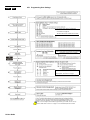
2.0 Basic Operation
The following sections will introduce you to the roles of the buttons, lights, and messages on your keypad.
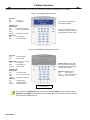
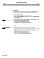
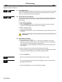
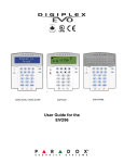
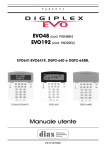
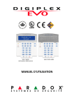
Figure 1: LCD Keypad Basic Overview
AC Light:
ON
= AC power
OFF
= Power failure
The LCD screen will guide you
with detailed messages.
STATUS Light:
When Green:
ON
= All zones are closed.
OFF
= One or more zones are
open.
FLASH
= Exit Delay in progress
Use the arrow buttons to scroll
through the current menu when the
arrows appear in the LCD screen.
When Red:
ON
= Area(s) armed
OFF
= Area(s) disarmed
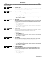
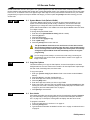
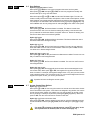
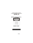
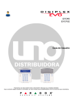
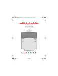
Figure 2: DGP2-648BL LED Keypad Overview
AC Light:
ON
= AC Power (OK)
OFF
= Power failure
AREA Lights: (A1, A2, A3 and A4)
ON
= Area armed
OFF
= Area disarmed
FLASH
= Area in alarm
ACTION Lights: (Access, Stay,
Force, Byp, Mem, Trbl and Prg)
Lights will illuminate according to
the status of the system.
STATUS Light:
When green:
ON
= All zones closed
OFF
= One or more zones are
open
FLASH
= Exit Delay in progress
When red:
ON
= Area(s) armed
OFF
= Area(s) disarmed
FLASH
= System in Alarm
Numerical Lights: (Zones)
ON
= Zone is open
OFF
= Zone is closed (OK)
FLASHES = Zone / fire loop
The keypad will display the status
of all its assigned areas.
For all keypads, the [ENTER] key will save and exit, and the [CLEAR] key will exit without saving.
[ENTER] and [CLEAR] represent the LCD/LED keypads’ enter and clear keys unless both keys are
shown to have a different function.
2 User Guide
LCD
LED
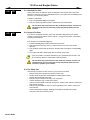
2.1 Auditory Feedback (Beep Tones)
When you enter information on the keypad, the keypad will guide you with beep tones to
communicate the acceptance or rejection of your entries.
Confirmation Beep: When an operation (i.e. arming/disarming) is successfully entered
or when the system switches to a new status/mode, the keypad emits an intermittent
beep tone (“BEEP-BEEP-BEEP-BEEP-BEEP”).
Rejection Beep: When the system reverts to a previous status, or when an operation is
incorrectly entered, the keypad emits a continuous beep tone (“BEEEEEEEEEEP”).
LCD
LED
2.2
Confidential Mode
Your installer can program keypads to not display the status of your system automatically
by changing the keypad to Confidential Mode.
In Confidential Mode:
• The zones and status messages will NOT be displayed
• The indicator lights will NOT illuminate
• Depending on how your keypad was programmed by your installer, you must either
press a button or enter your user access code to illuminate the indicator lights and
activate Normal Mode.
EVO Systems 3
3.0 Partitioned System
Your installer can set your keypad to recognize separate protected areas. A separated system is called a partitioned system,
which can be useful in situations where shared security systems are more practical. For example, a company that has both
an office and a warehouse area, can arm and disarm each area separately while controlling access to each area. Therefore,
one person may have access to only one area, whereas another person may have access to all areas. Access to the areas is
determined by the User Access Code.
3.1
Area Display
The Area Status Display enables you to see the status of the individual areas within a
partitioned system. Your installer can partition the system into separate areas.
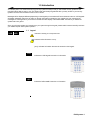
To view the status of the areas:
1. Enter your [ACCESS CODE], and then press the [1] button.
2. Press the button corresponding to the area (i.e. 1, 2,...8), or use the [S] and [T]
buttons and press [ENTER] when the area you want to view appears on the screen.
3. Press [CLEAR] to exit.
LCD
LED
4 User Guide
In Area Status Display mode, the following information will scroll on the LCD screen:
• ready: if all zones in the selected area are closed.
• not ready: if zones in the selected area are open.
• Front Door Open: if there is an open zone within that area.
• Trouble(s): (section 8.0 on page 17) if a trouble has occurred.
• Alarms in Memory: (section 5.3 on page 8) if an alarm has occurred.
• Armed; Force Armed; Instant Armed; Stay Armed: displays the arming status of the selected
area.
In Area Status Display, the following will illuminate for the area selected:
• The area lights (A1, A2, A3, and A4) if the associated area is armed. For example, if
you have selected area 3 and it is currently armed, A3 will illuminate.
• The numerical light(s) representing any open zone(s) in a corresponding area or
areas.
• The MEM action light if any alarms have occurred.
• The TRBL action light if any troubles are occurring.
• The STAY action light if the area is Stay or Instant Armed.
• The FORCE action light if the area is Force Armed.
• The BYP action light if zones are bypassed.
4.0 Arming
When your system is armed, it can respond to any breach in the protected zones by causing an alarm and sending a report to
your monitoring station.
LCD
LED
LCD
LED
4.1
Exit Delay Timer
When you arm your system, it will trigger the Exit Delay Timer to provide you with enough
time to exit the protected area before the system is armed.
4.2
Regular Arming
This method is used for the everyday arming of your system. All zones within the
protected area must be closed to Regular arm the system.
To Regular arm the system:
1. Enter your [ACCESS CODE].
2. Press the [ARM] button.
3. If you have access to more than one area, select the area(s) you wish to Regular arm
(refer to section 3.1 on page 4).
LCD
LED
4.3
Stay Arming
Stay arming will partially arm your system to permit you to remain in your home or office
by arming the outer zones (perimeter) of the protected area (i.e. doors and windows).
To Stay arm:
1. Enter your [ACCESS CODE].
2. Press the [STAY] button.
3. If you have access to more than one area, select the area(s) you wish to Stay arm
(refer to section 3.1 on page 4).
LCD
LED
4.4
Instant Arming
This feature is the same as Stay arming except that there is no Entry Delay. Therefore,
any armed zone that is breached will immediately generate an alarm.
To Instant arm:
1. Enter your [ACCESS CODE].
2. Press the [5] button.
3. If you have access to more than one area, select the area(s) you wish to Instant arm
(refer to section 3.1 on page 4).
LCD
LED
4.5
Force Arming
Force arming allows you to quickly arm your system when zones are open. However,
once the open zone is closed, your system will then arm that zone as well.
To Force arm:
1. Enter your [ACCESS CODE].
2. Press the [FORCE] button.
3. If you have access to more than one area, select the area(s) you wish to Force arm
(refer to section 3.1 on page 4).
LCD
LED
4.6
Bypass Programming
You can bypass certain zones when you arm the protected area(s). When a zone is
bypassed, it will be ignored the next time your system is armed. Once your area is
disarmed, the system will unbypass the zone.
To Bypass a zone:
1. Enter your [ACCESS CODE].
2. Press the [BYP] button.
EVO Systems 5
3. Enter the zone number (i.e. 01, 02,...96), or use the [S] and [T] buttons and press
[BYP] once the zone you want to bypass appears on the screen. If bypassed, the byp
light does not appear on the screen and the keypad emits a rejection beep, you may
not have access to bypass that zone.
4. Repeat step 3 until all zones you want to bypass have been selected.
5. Press the [ENTER] button to save and exit.
To view all bypassed zones.
1. Enter your [ACCESS CODE].
2. Press the [BYP] button.
3. Scroll through the zones using the [S] and [T] buttons to view zone status. (LCD
Keypads)
In order to bypass a zone, the following conditions must be met:
• The zone must have the Bypass option programmed by your installer.
• The Bypass option must be enabled in your User Options.
• Your user access code must have access to the zone’s Area Assignment.
• The zone’s area must be disarmed before the zone can be bypassed.
Fire Zones cannot be bypassed.
4.6.1 Bypass Recall
Bypass Recall reinstates the zones that were bypassed the last time your system
was armed.
To activate Bypass Recall:
1. Enter your [ACCESS CODE].
2. Press the [BYP] button.
3. Press the [MEM] button.
Zones bypassed the last time your system was armed are bypassed.
4. Press the [ENTER] button to save and exit.
LCD
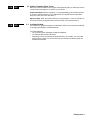
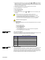
4.6.2 One-Touch Buttons
If enabled by your installer, you can access the following features without using your user
access code by pressing and holding the desired One-Touch button.
LED
Button
[ARM]
[STAY]
[FORCE]
[BYP]
[DISARM]
[5]
[6]
[7]
LCD
LED
6 User Guide
4.7
Table 1: One Touch Button
Feature
Regular arm
Stay arm
Force arm
Bypass Programming
Disarm a Stay/Instant armed area
Instant arm
Change display settings
View Event Record display (LCD Keypads only)
Keyswitch Arming
A key can be used to arm and disarm your system using two forms of keyswitches. With
a Maintained Keyswitch, place the key in the “ON” position to arm your system, and
place the key in the “OFF” position to disarm your system. With a Momentary Keyswitch,
place the key in the “ON” position briefly then place it back in the “OFF” position to arm
the system. Repeat this process to disarm with a Momentary Keyswitch.
LCD
LED
4.8
Auto-Arming
If enabled by your installer, you can set the time that an area will arm itself automatically.
4.8.1 Timed Auto-Arming
Your installer can set Timed Auto-Arming to function in either Force or Stay arming
mode. A sixty-second (default value) Exit Delay sequence will begin prior to your
system automatically arming itself at the programmed time.
To set the Auto-Arming timer:
1. Enter your [ACCESS CODE].
2. Press the [0] button.
3. Press the [MEM] button.
4. If you have access to more than one area, press the area’s number, or use the
[S] and [T] buttons and press the [ACC] button when the area you want to
program appears on the screen.
5. Enter the time you want the area to be armed according to the 24-hour clock
(i.e. 9 a.m. is 09:00 and 9 p.m. is 21:00).
6. Press the [ENTER] button to save and exit.
If you are using the DGP2-648BL LED keypad, The MEM action light will
flash if a time is not already programmed. The PRG action light, the area
light of the chosen area, and the first number of the previous time set will
illuminate (10 light = zero).
4.8.2 No Movement Auto-Arming
Your system can be programmed to send a report to your monitoring station and/
or arm the system if there is no activity in the area during a specified period of
time. Your installer can set No Movement Auto-Arming to function in either
Regular or Stay arming mode.
EVO Systems 7
5.0 Disarming
When your system is disarmed, it deactivates any alarms in progress, and it deactivates the zones so the alarm will not be
triggered if zones are breached.
LCD
LED
LCD
LED
5.1
Entry Delay Timer
Your installer will program designated entry points (i.e. the front door) with an Entry Delay
Timer. This delay gives you time to enter the armed premises and enter your code to
disarm your system before the alarm is triggered.
5.2
Disarming an Armed System
You can only disarm an area to which your user access code is assigned. User access
codes with the “Arm Only” (section 6.6 on page 13) option enabled cannot disarm an
armed system.
How do I disarm the system?
1. Enter your [ACCESS CODE].
2. Press the [DISARM] button. If you have access to more than one area, select the
area(s) you wish to disarm (refer to section 5.2 on page 8).
To disarm a system in alarm:
1. Enter your [ACCESS CODE].
2. In the case of a false alarm, call your monitoring station quickly to advise them of the
false alarm.
In the case of a burglar alarm, leave the premises and call the Police from a
safe location.
5.3
Alarm Memory Display
When an alarm occurs in a zone:
• The area and zone (i.e. Alarm Area 1 - Front Door) are displayed / zone’s LED
flashes even when the system is armed. The notification continues until disarming,
even if the zone is restored. (EVO641 / EVO641R only)
• The alarm memory will be erased after the next alarm occurs and a valid code has
been entered.
To view the alarms that occurred the last time the system was armed:
1. When the system is disarmed, the LCD keypad’s screen will display Alarm in Memory:
Press [mem]. The DGP2-648BL LED’s MEM action light will illuminate.
2. Press the [MEM] button.
LCD
LED
Each zone that was breached while armed will appear below Alarm in:.
The MEM action light will flash and the numerical light(s) for each zone whose alarm
was triggered will illuminate.
3. Press the [CLEAR] button to exit the Alarm Memory Display.
8 User Guide
6.0 Access Codes
Access Codes allow access to the system. Your system supports up to 999 user access codes. Codes are given a User
Number between 002 and 999 (User Number 001 is the System Master Code). Your installer will program user access codes
to be four, six, or variables of one to six digits in length. Each digit can be any value between zero and nine. If your installer
programmed your system to accept a variable code length, you have to press the [ENTER] button after entering your user
access code.
LCD
LED
6.1
System Master Code (Default 123456)
The System Master Code will give you access to all the features available on your
system, as well as the ability to add, modify, or delete any user access codes. We
suggest that you change this code to prevent others from accessing and changing
options without authorization. Your installer can set the System Master Code to be either
4 or 6 digits in length.
To change the System Master Code:
1. Enter the current [SYSTEM MASTER CODE] (default: 123456).
2. Press the [0] button.
3. Press the [ACC] button.
4. Enter the numbers [0] [0] and [1].
5. Enter a [NEW CODE].
6. Press the [ENTER] button to save and exit.
The System Master Code has access to all Access Control doors and all
Access Control features at all times. Only the card’s serial number and the
choice of arming method can be changed. If the other options are manually
changed, the System Master Code will immediately revert to its original
programming.
You can assign a label (name) to a user access code at any point during the
“Programming User Access Code” process. Refer to section 6.3 on page 9 to
assign a User Label.
LCD
6.2
Copy User Options
This feature allows you to copy the User Options, Access Control Options, and Area
Assignments from one user access code to another. All User Options are copied except
the User Code, Card Assignment, and User Label.
To copy user options:
1. Enter your [ACCESS CODE] (System Master Code or user access code with Master
feature).
2. Press the [0] button, and then the [ACC] button.
3. Enter the 3-digit User number you wish to copy TO.
4. Press the [MEM] button.
5. Enter the 3-digit User number you wish to copy FROM.
6. Enter a user code. If the user code is of variable length, press the [ENTER] button after
entering the user code. If necessary, assign an Access card (step 13 in section 6.5.1
on page 12) and User Label (section 6.3 on page 9).
7. Press [ENTER] to save and exit.
LCD
6.3
User Labels
User labels personalize user access codes and can be assigned by pressing [ENTER] at
any point after step 4 during the programming of user access codes (refer to section
6.5.1 on page 12). For Example, LCD keypads can display John Smith Select Action.
To program a user label:
1. At any point after step 4 in section 6.5.1 on page 12:
2. Press the [ENTER] button.
3. Type the desired characters as detailed in section 6.3.1 on page 10 and section 6.3.2
on page 10.
EVO Systems 9
4. Press the [S] button to move the cursor to a new space.
5. Repeat steps 2 and 3 until the desired label is complete.
6. Press the [ENTER] button to save and exit.
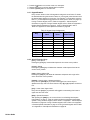
6.3.1 Keypad Buttons
Every numeric button on the LCD keypads is assigned a set of letters. To obtain
the desired letter using the numeric buttons on your keypad, press the button until
the desired letter appears on the screen. For example, if you wanted to enter the
letter “C” you would press the [1] button three times (refer to Table 2 on page 10).
If using a Hebrew keypad, refer to Table 6 in Appendix 1: Hebrew Special
Characters on page 26. If using a Russian keypad, refer to Table 8 in Appendix 2:
Russian Special Characters on page 27. If using a Greek keypad, refer to
Table 10 in Appendix 3: Greek Special Characters on page 28.
Table 2: Keypad Letter Assignments
Key
Press Key
Once
Press Key
Twice
Press Key
Three Times
[1]
A
B
C
[2]
D
E
F
[3]
G
H
I
[4]
J
K
L
[5]
M
N
O
[6]
P
Q
R
[7]
S
T
U
[8]
V
W
X
[9]
Y
Z
6.3.2 Special Function Keys
[STAY] = Insert Space
Pressing the [STAY] key inserts a blank space in the current cursor position.
[FORCE] = Delete
Pressing the [FORCE] key will delete the character or blank space found at the
current cursor position.
[ARM] = Delete Until the End
Pressing the [ARM] key will delete all characters and spaces to the right of the
cursor and at the cursor's position.
[DISARM] = Numeric Keys / Alphanumeric Keys
Every time the [DISARM] key is pressed it will toggle from numeric keys to
alphanumeric keys and vice versa. Numeric: Keys [0] to [9] represent numbers 0
to 9.
[BYP] = Lower Case / Upper Case
Every time the [BYP] key is pressed it will toggle the case setting from lower to
upper case and vice versa.
[MEM] = Special Characters
After pressing the [MEM] key, the cursor will turn into a flashing black square.
Using Table 3 on page 11, enter the 3-digit number that represents the desired
symbol. If using a Hebrew keypad, refer to Table 7 in Appendix 1: Hebrew Special
Characters on page 26. If using a Russian keypad, refer to Table 10 in Appendix
2: Russian Special Characters on page 27. If using a Greek keypad, refer to Table
12 in Appendix 3: Greek Special Characters on page 28.
10 User Guide
Table 3: Special Characters Catalogue
LCD
LED
LCD
LED
6.4
Deleting User Access Codes
To delete user access codes, follow steps 1 to 5 in section 6.5.1 on page 12. Once the
information is erased, press the [ENTER] button to save and exit.
6.5
Programming User Access Codes
The System Master and Users with the Master feature can program user access codes
with User Options and Area Assignments. The section 6.5.1 on page 12 describes the
steps you would follow to program user access codes. If you wish to program user
access codes using the NEware Software, please contact your installer for information.
If the keypad emits a rejection beep at any point during the programming procedure, you
may have chosen an existing user code or you do not have access to certain User
Options (section 6.6) and Area Assignments (step 7 in section 6.5.1 on page 12). Users
with the Master feature can only assign User Options and Area Assignments that they
are assigned to. For example, if a User with the Master feature is assigned User Option 1
and Area 2, they can only assign Option 1 and Area 2 to a user access code.
EVO Systems 11
LCD
LED
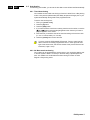
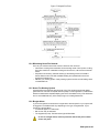
6.5.1 Programming User Settings
Notes:
- For a detailed description of the User Options,
see section 6.6 on page 13.
- By default, all users can regular arm the system.
Note:
- For a detailed description of the Access Control
User Options, see section 6.7 on page
User Labels on page 9.
NOTE: If no area is assigned, and if PGMs are programmed by your installer, the user can only
control the PGMs. Refer to section 9.1 on page 19 for a more detailed explanation of PGMs.
12 User Guide
LCD
LED
6.6
User Options
Options [1] and [2]: Master Feature
When option [1] is OFF, the User cannot program other users into the system.
When option [1] is ON and option [2] is OFF, the user can program and modify user
access codes (P.I.N. only) and User Labels.
When both options [1] and [2] are ON, the user has Full Master rights. The user can
create or modify user access codes, User Options, User Access Control Options, Access
Card Numbers, User Labels and Area Assignments according to their own programming.
For example, if the Full Master User has access to area #1 and option [4] (Bypass) only,
the Full Master user can only assign area #1 and option [4] to other users in the system.
Option [3]: Duress
When option [3] is ON, the Duress feature is enabled. This feature is used when
someone forces a user to arm or disarm an area(s). By entering a user access code
(P.I.N.) reserved for the Duress feature, the system will arm or disarm the area(s), and
then send a silent alarm to the monitoring station.
Option [4]: Bypass
When option [4] is ON, the Bypass feature is enabled. This feature allows the user to
deactivate zones when arming the area(s).
Option [5]: Arm Only
When option [5] is ON, the Arm Only feature is enabled. The user can arm assigned
areas with either a card or code, but cannot disarm. When the option is OFF, the user
can either arm or disarm assigned areas.
Option [6]: Stay & Instant Arm
When option [6] is ON, the Stay and Instant arm features are enabled. The user can now
Stay or Instant arm their assigned areas.
Option [7]: Force Arm
When option [7] is ON, the Force arm feature is enabled. The user can now Force arm
their assigned areas.
Option [8]: Area Access
When option [8] is ON, the keypad will permit access to all the areas assigned to the
user access code. When option [8] is OFF, the keypad will only permit access to the
areas it controls. For example, the keypad is assigned area 1 only, and your user access
code is assigned areas 1 to 8. If the option is ON, you can access all eight areas from the
keypad. If the option is OFF, you can only access area 1.
By default all users can Regular arm the system.
LCD
6.7
Access Control User Options
Option [1]: Access Control
When option [1] is ON, the user can gain access to an access control door when Access
Control is enabled in the system. A user that is not assigned to any partition, but has the
Access Control option (Option [1]) enabled, can now gain access to an access control
door by entering a code # (P.I.N.) and then pressing the [ACC] keypad key. When the
option is OFF, the user cannot access an Access Control door.
Option [2]: Can Disarm with Access Card
When option [2] is ON, a User’s Access Control card can unlock and disarm an armed
Access Control door. When option [2] is OFF, follow the settings in option [8] on page
15.
For option [2] to function in the ON position, option [5] “Arm Only” in the
User Options must be disabled (refer to section 6.6 on page 13).
EVO Systems 13
Option [3]: Card with Extended Unlocked Period
When option [3] is ON, “Extended Unlocked Period” is enabled. “Extended Unlocked
Period” refers to the time period programmed into each Access Control door by your
installer that extends the unlocked time of the door. For example, if your installer sets the
Unlocked period of the door to 30 seconds and the Extended Unlocked Period to 15
seconds, a user access code with “Extended Unlocked Period” enabled will have a total
of 45 seconds to pass through the door.
Options [4] and [5]: Arming with Card
Options [4] and [5] define the type of arming when arming with an Access Control card
(refer to section 7.2.1 on page 15). You can either Regular arm, Stay arm, Force arm, or
Disable the Arming with Card feature.
[4] ON, [5] OFF = Regular Arm
[4] OFF, [5] ON = Stay Arm
[4] and [5] ON = Force Arm
[4] and [5] OFF = Disable the Arming with Card feature
Option [6]: Add Tolerance Window to Schedule
When option [6] is ON, the Schedule Tolerance Window feature is enabled. This feature
extends a user’s scheduled access period through an Access Control door by the
amount programmed by your installer. For example, if the user’s assigned schedule for
the door is Monday to Friday from 9:00 a.m. to 5:00 p.m., and your installer sets the
“Tolerance Window” at one hour, the user with the “Schedule Tolerance Window”
enabled will be able to enter and exit one hour before and after their scheduled time for
that door.
Option [7]: Code Follows Schedule
When option [7] is ON, users can use their access codes only during their scheduled
hours assigned in step 8 in section 6.5.1 on page 12. When the option is OFF, users can
use their access codes at any time.
Option [8]: Card to Unlock and Code to Disarm
Option [8] functions only if option [2] in section 6.7 is OFF. When option [8] is ON, a
user can use an Access Control card to unlock an armed Access Control door, however
the user must enter a user access code to disarm the armed area. When option [8] is
OFF, a user can gain access to an Access Control door only if the door’s area(s) is
already disarmed.
For option [8] to function in the ON position, option [5] “Arm Only” in the
User Options must be disabled (refer to section 6.6 on page 13).
14 User Guide
7.0 Using Access Control
LCD
LED
7.1
Entering & Exiting
Depending on how your system is installed and on the type of keypad, there are various
ways to enter and exit Access Control doors:
•
•
•
•
7.2
/
LCD EVO641R
DGP2-641RB only
/
LCD EVO641R
DGP2-641RB only
Present your Access Control card to the reader or the
EVO641R or DGP2-641RB keypad. The system will
verify that the card is allowed access according to its
assigned Access Level and Schedule. If it is accepted,
the system will unlock the door. The reader’s light can
be programmed by the installer to turn green or
extinguish briefly to indicate that the door can be
opened.
When the motion detector detects movement (Request
for Exit), it will unlock the door to permit passage from
inside.
Enter your user access code on the keypad and press
[ACC].
If the Access Control door is on a “Door Unlocked
Schedule”, you may be able to open Access Control
doors without using a user access code or an Access Control card. Depending on the
door’s programming, the door can remain unlocked during the entire programmed
schedule or the door can unlock once a valid Access Control card is presented to the
reader during the schedule and then will remain unlocked for the remainder of the
schedule.
Arming and Disarming with Card
7.2.1 Arming with Card
• presented to a door during its assigned Schedule (refer to step 8 in section
6.5.1 on page 12).
• presented to a door within its assigned Access Level (refer to step 8 in section
6.5.1 on page 12).
• programmed to allow arming (options [4] and [5] in section 6.7 on page 13).
• assigned to all areas that are assigned to the Access Control door (refer to step
7 in section 6.5.1 on page 12), or assigned to at least one of the areas assigned
to the Access Control door depending on how your installer has programmed
the Access Control door.
7.2.2 Disarming with Card
To disarm and unlock an Access Control door when the area assigned to it is
armed, present your Access Control card to the reader or EVO641R / DGP2641RB keypad (door). The Access Control card must be:
• presented to a door during its assigned Schedule (refer to step 8 in section
6.5.1 on page 12).
• presented to a door within its assigned Access Level (refer to step 8 in section
6.5.1 on page 12).
• programmed to allow disarming (option [2] in section 6.7 on page 13).
• assigned to all areas that are assigned to the Access Control door (refer to step
7 in section 6.5.1 on page 12), or assigned to at least one of the areas assigned
to the Access Control door depending on how your installer has programmed
the Access Control door.
EVO Systems 15
LCD
LED
7.3
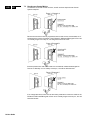
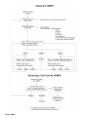
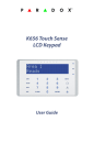
How Access Control Works
To illustrate how Access Control functions, we will use three simple Access Control
System examples:
Figure 3: Example A
Bonnie’s Access Control card is programmed with Access Level 01 and Schedule 01. If
she presents her card to the reader or the EVO641R / DGP2-641RB keypad on Door 02
on Tuesday, August 3 at 3:00 p.m., she will gain access to the room.
Figure 4: Example B
If Bonnie presents her card to the reader or the EVO641R / DGP2-641RB keypad on
Door 02 on Saturday or on a Holiday at 3:00 p.m., she will be denied access.
Figure 5: Example C
If we change Bonnie’s Access Level to 02 and she presents her card to the reader or the
EVO641R / DGP2-641RB keypad on Door 02 on Tuesday, August 3 at 3:00 p.m., she will
be denied access.
16 User Guide
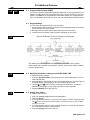
8.0 Trouble Display
LCD
LED
8.1
Trouble Display
If your system experiences any problems, Trouble(s) [TRBL] to View will appear on the
screen, or the TRBL action light will illuminate. The Trouble Display will only display the
troubles that occur in the area(s) to which the keypad has been assigned. Potential
troubles have been sorted into eight groups. Only the troubles which are relevant to you
are listed and described below. If a trouble that is not described or listed below appears,
contact your installer. To view the Trouble Display:
1. Press the [TRBL] button.
LCD
The Group Heading with the trouble will appear on the screen. Press the [S] and [T]
buttons to scroll between the Groups experiencing a trouble.
LED
On the DGP2-648BL LED keypad, The TRBL action light will flash and the numerical
light(s) representing group heading number(s) will illuminate.
2. Press the [NUMBER] of the Trouble you wish to view.
We strongly suggest that if any troubles occur, contact your installer
immediately to have your system serviced.
8.1.1 Group 1: System
[1] AC Failure
The control panel has detected a power failure. This means that your system is
running on the backup battery. If this trouble occurs when your establishment is
not experiencing a power failure, call your installer for repairs.
[2] Battery Trouble
The backup battery is disconnected, needs to be recharged, or replaced.
[5] Bell Absent
The system has detected that the bell or siren is not connected.
8.1.2 Group 2: Communicator
[1] TLM1
The control panel is unable to access the main telephone line.
[2] to [5] Fail to Communicate (1 to 4)
The control panel tried all assigned telephone numbers and failed to contact the
monitoring station.
[6] Fail to Communicate PC
The control panel is unable to communicate with the WinLoad software.
8.1.3 Group 5: Zone Tamper
The zone(s) that was tampered with will be displayed on the LCD screen.
8.1.4 Group 6: Zone Low Battery
If a wireless device's battery needs to be replaced, the zone that is assigned to
the device will be displayed on the LCD screen.
8.1.5 Group 7: Zone Fault
A wireless device is no longer communicating with its receiver, or a connection or
CleanMeTM trouble is occurring with your smoke detectors.
EVO Systems 17
8.1.6 Group 8: Clock Loss
The time and date have been reset to the default. This is the only trouble that we
recommend that you correct. Clock Loss [8] to Set will appear on the LCD screen
after you press the [TRBL] button or the [ ] key. Refer to section 9.4 on page 19
to set the time and date.
LCD
8.2
Event Record Display
The Event Record Display will record the user-initiated actions that occurred in your
system as well as any alarms or troubles (i.e. “Access Granted”). You will only be able to
view the events that occurred in the area(s) assigned to your user access code.
-Only available on LCD keypads.
To view the Event Record:
1. Enter your [ACCESS CODE].
2. Press the [7] button.
3. If you have access to more than one area, select the area(s) you wish to view.
4. Use the [S] and [T] buttons to scroll between the events.
5. Press the [CLEAR] button to exit.
Once you have entered Event Record Display mode, you can change the order that the
Event Record screens appear by pressing the [7] button. If you already know the number
of the event you want to view, press the [MEM] button after step 3 above, and then enter
the event's number.
18 User Guide
9.0 Additional Features
LCD
LED
9.1
Programmable Outputs (PGMs)
Your system includes Programmable Outputs (PGMs) that can be programmed by your
installer. A PGM triggers when a predetermined event or series of events occurs in your
system. The PGMs can be programmed to reset smoke alarms, turn on light switches,
open or close garage doors and much more. Ask your installer about this useful feature.
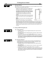
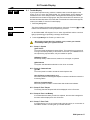
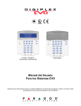
9.2
Keypad Settings
You can modify the keypad settings to suit your needs.
1. Scrolling Speed refers to the amount of time that a message will remain on the screen
before moving to the next message.
2. Backlight refers to the illumination behind the buttons and LCD screen.
3. Contrast refers to how dark or pale characters will appear on the screen.
Figure 6: Modifying LCD screen settings on LCD Keypads
LCD
‡
‡
†
‡
*This feature cannot be accessed via One-Touch Buttons (see section 4.6.2 on page 6).
†When keypad mute is enabled, only confirmation, rejection, and key-press beeps are audible.
‡
EVO641 / EVO641R only
LED
9.3
Modifying illumination settings on the DGP2-648BL LED
To modify illumination settings:
1. Enter your [ACCESS CODE]. Your keypad will emit a Confirmation Beep. The ACCESS
action light will flash.
2. Press the [6] key. Your keypad will emit a Confirmation Beep, the Prg action light will
illuminate and the numerical light for the current setting will illuminate.
3. Use the [S] and [T] keys to increase or decrease the illumination. The range is
between numerical light 1 to 8 (1 being the lowest and 8, the brightest).
4. Press the [ENTER] key to save and exit.
LCD
9.4
Setting Time & Date
To reset the time and date:
1. Enter your [ACCESS CODE] and press the [TRBL] button.
2. Press the [8] button.
3. To change the time, place the cursor under the number you want to change by using
the [S] button and enter the time according to a 24-hour clock (i.e. 9 a.m. is 09:00
and 9 p.m. is 21:00).
4. To change the date, place the cursor under the number you want to change and enter
the correct date according to year/month/day.
5. Press the [ENTER] button to save and exit.
EVO Systems 19
On the DGP2-648BL LED keypad, follow this procedure:
LED
LCD
1. Enter your [ACCESS CODE] and press the [TRBL] button.
2. Press the [8] button.
3. Enter the hour and minutes according to the 24-hour clock (i.e. 9AM is 09:00 and
9PM is 21:00).
4. Enter the correct date according to yyyy/mm/dd.
5. Press [CLEAR].
LED
9.5
Programming Chime Zones
You can program the keypad to emit a rapid, intermittent beep tone whenever designated
zones are opened or only when opened between certain hours. These zones are
referred to as Chime Zones. Your installer can also program your Chime zones to beep
upon closure.
How do I program chime zones?
1. Enter your [ACCESS CODE].
2. Press the [9] key.
3. Press the [1] key to chime a zone. Enter the number corresponding to the zone to be
chimed, or use the [S] and [T] buttons to scroll the list of zones. Press the [ACC]
button to chime or unchime the zone that appears on the screen. Press [ENTER] to
save.
OR
Press the [2] button to set the time period a chimed zone will beep. Enter the time
that the chimed zone(s) will start beeping when opened (HH:MM). Enter the time that
the chimed zone(s) will stop beeping when opened (HH:MM).
4. Press [CLEAR] to exit chime programming.
LCD
LED
9.6
Panic Alarms
Your system can be programmed to send an alarm to your monitoring station to request
help from the police, a medical facility, the fire department, or anyone you wish when you
press a predetermined combination of buttons. To generate a panic alarm,
simultaneously press and hold the button combinations displayed in Table 4 on page 20.
Your installer can program the alarm to be either silent or audible.
Table 4: Panic Buttons
Panic Alarm Types
LCD
LED
9.7
Buttons to be pressed and held
simultaneously
Emergency Panic
Press & hold the [1] and [3] buttons
Auxiliary Panic
Press & hold the [4] and [6] buttons
Fire Panic
Press & hold the [7] and [9] buttons
Quick Function Buttons
You will only need to use the Quick Function Buttons upon your installer’s or monitoring
station's request. Only the System Master Code or user access codes with the Master
feature enabled will be able to access these functions.
To access the Quick Function Buttons:
1. Enter your [ACCESS CODE]
2. Press the [0] button.
3. Press the:
[STAY] to send a test report to the monitoring station.
[FORCE] to call the WinLoad software.
[ARM] to answer the WinLoad software.
[DISARM] to cancel communication with the WinLoad software.
20 User Guide
10.0 VDMP3 Plug-In Voice Dialer
The VDMP3 is a voice-assisted module that can be programmed to call up to 8
telephone numbers in the event of an alarm. You can also call the VDMP3 from an
outside line, enabling you to arm or disarm the system as well as activate up to 8 PGMs.
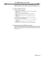
10.1 Calling the VDMP3 (outside line)
Connected to an answering machine:
1. From an outside line, dial the telephone number to which the VDMP3 is
connected.
2. When the line rings, hang up the telephone.
3. Dial the telephone number again within the time limit set by your
installer.
4. When the VDMP3 answers the line, you are prompted to enter your
access code.
5. Options are given to arm/disarm (1) and control features (PGMs) (2).
Not connected to an answering machine:
1. From an outside line, dial the telephone number to which the VDMP3 is
connected.
2. When the VDMP3 answers the line, you are prompted to enter your
access code.
3. Options are given to arm/disarm (1) and control features (PGMs) (2).
10.2 Receiving a Call From the VDMP3 (alarm in system)
When the VDMP3 calls because of an alarm in the system, the option is given to disarm
the system or disconnect (##). If you hang up without disarming or disconnecting, the
VDMP3 calls the next telephone number on its list (see Telephone Numbers in VDMP3
Setup Instructions).
EVO Systems 21
22 User Guide
11.0 Testing and Maintenance
11.1 Burglar Alarm Testing
Two people are needed to complete this test. One person will watch the screen on the
keypad while the other person walks around the protected areas and opens the zones
(i.e. opens the doors and windows that are protected, walk in the path of the motion
detectors, etc.). The screen will display the opened zones, but if a zone does not register,
contact your installer.
11.2 Fire Alarm Testing
Do NOT use an open flame or burning materials to test your fire detection devices. Your
installer will provide details on the best way to test your system.
11.3 System Maintenance
Under normal use your system requires no maintenance other than regular testing. We
recommend that your installer change the battery every three years.
LCD
LED
11.4 System Test
Speak to your installer before conducting a System Test since the system must be
programmed to respond to the test instructions. It is normally recommended that you
conduct the system test once a week, but contact your installer for instructions
concerning your particular system.
To conduct the system test:
1. Call your monitoring station to advise them that you are testing your system.
2. Enter your [ACCESS CODE].
3. Press the [8] button.
The system will test all its connections and can send a report to your monitoring station.
If the system detects a problem, the Trouble Display will show on the screen (refer to
section 8.0 on page 17). Call your installer for repairs if any troubles occur.
EVO Systems 23
12.0 Fire and Burglar Alarms
LCD
LED
12.1 Standard Fire Zone
During a fire alarm, the bell/siren emits an intermittent sound (BEEP-BEEP-BEEP) until
silenced or reset. If the zone is a Standard Fire Zone, your system can immediately send
an alert to your monitoring station.
To disarm a false alarm:
1. Enter your [ACCESS CODE] on the keypad.
2. Call your monitoring station quickly to advise them of the false alarm.
The Fire Zone may reset itself once the problem has cleared. If it does not,
simultaneously press and hold the [CLEAR] and [ENTER] buttons for two
seconds.
LCD
LED
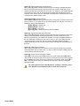
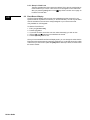
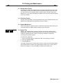
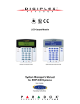
12.2 Delayed Fire Zone
If the zone is a Delayed Fire Zone, there is an automatic delay before your system
contacts your monitoring station. Refer to Figure 7 on page 25 to prevent unnecessary
reporting of false alarms.
If the fire alarm is accidentally triggered:
1. Press the [CLEAR] button within 30 seconds of the alarm.
2. Clear the problem from the area (i.e. clear the smoke from around the smoke
detector).
3. If the problem remains after 90 seconds, the alarm will sound again. Press [CLEAR]
again.
4. The system will delay reporting the alert for another 30 seconds.
If you are unable to cancel the false alarm, your system will send an alert. Call
your monitoring station to advise them of the false alarm.
The Fire Zone may reset itself once the smoke has cleared. If it does not,
simultaneously press and hold the [CLEAR] and [ENTER] buttons for two
seconds or speak to your installer.
12.3 Fire Safety Tips
How should you prepare in case of a fire in your home or business?
•
•
•
•
•
•
•
•
24 User Guide
Remind everyone to escape first, and then call for help.
Develop a fire escape plan and designate a meeting place outside.
Practice the escape plan frequently.
Plan two ways to escape from every room, if possible.
Practice feeling the way out with eyes closed.
Instruct everyone never to stand up during a fire, always crawl under the smoke and
keep mouths covered.
Instruct everyone never to return to a burning building for any reason; it may cost
them their life.
Check smoke alarms regularly. Working smoke alarms dramatically increase
everyone's chances of surviving a fire.
Figure 7: Delayed Fire Zone
12.4 Minimizing Home Fire Hazards
How can you avoid the three most common causes of fires at home?
• Never leave cooking food unattended. It’s the leading cause of fire injuries. Cooking
fires often result from unattended cooking and human error, rather than mechanical
failure.
• Stay alert when smoking. Careless smoking is the leading cause of fire deaths.
Smoke detectors and smoulder-resistant bedding and upholstered furniture are
significant fire deterrents.
• Maintain your heating system. Faulty heating systems are the second leading cause
of residential fires.
12.5 Home Fire Warning System
Household fires are especially dangerous at night. Fires produce smoke and deadly
gases that can overcome occupants while they sleep. To warn against fire, install smoke
detectors outside each separate sleeping area in the immediate vicinity of the bedrooms
and on each additional story of the family living unit, including basements.
12.6 Burglar Alarm
If your armed system is breached, the burglar alarm devices specific to your system will
be triggered. The feedback will vary depending on the type of keypad used. If your
keypad is in Normal Mode:
• In Alarm will appear on LCD screen.
• Bell or siren may be activated.
• The keypad may beep. The MEM action light will illuminate.
In case of a burglar alarm, leave the premises and call the police station
from a safe place.
EVO Systems 25
Appendix 1: Hebrew Special Characters
Refer to the following tables when programming the user labels of a Hebrew LCD keypad. Instead of using Table 2 on
page 10 and Table 3 on page 11, use Tables 9 and 10 below. Refer to section 6.3 on page 9 for information on programming
user labels.
Table 5: Hebrew Keypad Letter Assignment
Table 6: Hebrew Special Characters Catalogue
26 User Guide
Appendix 2: Russian Special Characters
Refer to the following tables when programming the user labels of a Russian LCD keypad. Instead of using Table 2 on
page 10 and Table 3 on page 11, use Tables 11 and 12 below. Refer to section 6.3 on page 9 for information on programming
user labels.
Table 7: Russian Keypad Letter Assignment
Table 8: Russian Special Characters Catalogue
EVO Systems 27
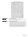
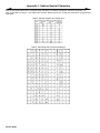
Appendix 3: Greek Special Characters
Refer to the following tables when programming the user labels of a Greek LCD keypad. Instead of using Table 2 on page 10
and Table 3 on page 11, use Tables 13 and 14 below. Refer to section 6.3 on page 9 for information on programming user
labels.
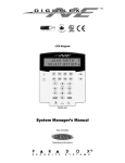
Table 9: Greek Keypad Letter Assignment
Key
Press key once
Press key twice
Press key three
times
[1]
#
$
)
[2]
&
'
<
[3]
*
3
+
[4]
-
.
/
[5]
0
[6]
2
4
5
[7]
6
7
(
[8]
%
;
9
016
±
032
048
0
064
@
017
½
033
!
049
1
065
A
018
034
ð
050
2
066
B
019
035
#
051
3
067
C
020
Ê
036
$
052
4
068
D
021
Ó
037
%
053
5
069
E
022
¸
038
&
054
6
070
F
023
ž
039
´
055
7
071
G
024
040
(
056
8
072
H
025
041
)
057
9
073
I
026
ª
042
*
058
:
074
J
027
Ú
043
+
059
;
075
K
028
=
044
,
060
<
076
L
029
~
045
-
061
=
077
M
030
2
046
.
062
>
078
N
031
3
047
/
063
?
079
O
28 User Guide
1
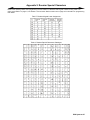
Table 10: Greek Special Characters Catalogue
096
112
128
144
160
176
p
Ç
É
á
081
097
113
129
145
161
177
Q
a
q
ü
æ
í
¨
082
098
114
130
146
162
178
R
b
r
é
Æ
ó
°
083
099
115
131
147
163
179
S
c
s
â
ô
ú
è
084
100
116
132
148
164
180
T
d
t
ä
ö
¢
´
085
101
117
133
149
165
181
U
e
u
à
ò
£
½
086
102
118
134
150
166
182
V
f
v
å
û
¥
¼
087
103
119
135
151
167
183
W
g
w
ç
ù
Pt
x
088
104
120
136
152
168
184
X
h
x
ê
ÿ
¶
÷
089
105
121
137
153
169
185
Y
i
y
ë
Ö
i
£
090
106
122
138
154
170
186
Z
j
z
è
Ü
Ã
Š
091
107
123
139
155
171
187
[
k
{
ï
ñ
ã
«
092
108
124
140
156
172
188
\
l
|
î
Ñ
Õ
»
093
109
125
141
157
173
189
]
m
}
ì
a
õ
¼
094
110
126
142
158
174
190
^
n
~
Ä
o
Ø
÷
095
111
127
143
159
175
191
o
D
Å
¿
ø
¯
080
P
192
Û
208
‰
224
b
240
t
193
€
209
†
225
g
241
u
194
•
210
§
226
d
242
c
195
211
¶
227
e
243
y
196
ø
212
G
228
z
244
w
197
¦
213
229
h
245
q
198
Ø
214
Q
230
q
246
u
199
Æ
215
L
231
i
247
t
200
¨
216
232
k
248
R
201
È
217
P
233
l
249
202
218
S
234
m
250
F
203
Î
219
°
235
n
251
204
°
220
F
236
x
252
ò
205
•
221
Y
237
p
253
206
®
222
W
238
r
254
207
©
223
a
239
s
255
Index
A
Copy User Options ...........................................................................9
Access Codes
Deleting .................................................................................. 11
Labelling ................................................................................... 9
Programming .......................................................................... 11
System Master ......................................................................... 9
User .......................................................................................... 9
D
Access Control ............................................................................... 13
Entering & Exiting ................................................................... 15
Access Control User Options
Access Control ....................................................................... 13
Add Tolerance Window to Schedule ...................................... 14
Arming with Card .................................................................... 14
Can Disarm with Access Card ............................................... 13
Card to Unlock and Code to Disarm ...................................... 14
Code Follows Schedule ......................................................... 14
Extended Unlocked Period ..................................................... 14
Date, Set .........................................................................................19
Deactivating a Security System ........................................................8
Delay Timer
Entry .........................................................................................8
Exit ............................................................................................5
Delayed Fire Zone ..........................................................................24
Deleting User Access Codes ..........................................................11
DGP2-648BL LED Keypad Overview ...............................................2
Disarming
Armed System ..........................................................................8
with Card ................................................................................15
Add Tolerance Window to User Schedule ..................................... 14
Display
Alarms In Memory ....................................................................8
User Actions in Memory .........................................................18
Alarm Memory Display ..................................................................... 8
Duress, in User Options .................................................................13
Alarm,Testing ................................................................................. 23
Area Access, in User Options ........................................................ 13
E
Area Display ..................................................................................... 4
Emergency Buttons ........................................................................20
Arming
Automatic Arming ..................................................................... 7
Force Arming ............................................................................ 5
Instant Arming .......................................................................... 5
Keyswitch Arming ..................................................................... 6
Regular Arming ........................................................................ 5
Stay Arming .............................................................................. 5
with Card ................................................................................ 15
Entering and Exiting, Access Control Doors ...................................15
Auto-Arming
No Movement Auto-Arming ...................................................... 7
Timed Auto-Arming .................................................................. 7
Entry Delay Timer .............................................................................8
Erasing User Access Codes ...........................................................11
Event Record Display .....................................................................18
Exit Delay Timer ...............................................................................5
Extended Unlocked Period .............................................................14
F
Fire
Delayed Fire Zone ..................................................................24
Minimizing Home Fire Hazards ..............................................25
Safety Tips ..............................................................................24
Standard Fire Zone .................................................................24
Warning System .....................................................................25
B
Basic Operation ................................................................................ 2
Battery
Disconnected ......................................................................... 17
Low, in a Zone ........................................................................ 17
Beep Tones
Confirmation beep .................................................................... 3
in Opened or Closed Zones, see Chime Zones
Rejection beep ......................................................................... 3
Bell Disconnected .......................................................................... 17
Burglar Alarms ............................................................................... 25
Buttons
One-Touch ............................................................................... 6
Quick Function ....................................................................... 20
Bypass
Bypass Recall .......................................................................... 6
Programming ............................................................................ 5
Fire Alarm, Testing .........................................................................23
Force Arming ....................................................................................5
G
Greek Special Characters ..............................................................28
H
Hebrew Special Characters ............................................................26
I
Ignoring Zones when Arming, see Bypass Programming
Instant Arming ..................................................................................5
K
C
Card, Access Control
Arming with ............................................................................ 15
Disarming with ........................................................................ 15
Characters, Special ........................................................................ 11
Chime Zones .................................................................................. 20
Clock, Set Time and Date .............................................................. 19
Code Follows Schedule ................................................................. 14
29 User Guide
Keypad, LCD
Buttons .....................................................................................2
Letter Assignment ...................................................................10
Lights ........................................................................................2
Messages .................................................................................2
Settings ...................................................................................19
Keyswitch Arming .............................................................................6
M
Master Code .................................................................................... 9
Master Feature, in User Options .................................................... 13
N
No Movement Auto-Arming ............................................................. 7
O
One Touch Button for the DGP-641BL/RB and the DGP-648 ......... 6
One-Touch buttons .......................................................................... 6
Outputs, Programmable (PGM) ..................................................... 19
P
Timer
Entry Delay ...............................................................................8
Exit Delay .................................................................................5
Trouble
AC Failure ...............................................................................17
Battery ....................................................................................17
Bell/Siren Disconnected .........................................................17
Clock .......................................................................................18
Communicator ........................................................................17
Fail to Communicate ...............................................................17
Fail to Communicate PC .........................................................17
Low Battery, Zone ..................................................................17
System ....................................................................................17
TLM1 ......................................................................................17
Zone Fault ..............................................................................17
Zone Tampering .....................................................................17
Panic Alarms .................................................................................. 20
U
Power Failure, see Trouble
Programmable Outputs (PGM)
19
Programming
Chime Zones ......................................................................... 20
User Access Codes ......................................................... 11–13
Q
Quick Function Buttons
Answer Winload Sofware ....................................................... 20
Call Winload Software ........................................................... 20
Cancel Communication with Winload Software ..................... 20
Send Test Report ................................................................... 20
R
Recall, Bypassed Zones .................................................................. 6
Unlocked Period, Extended ............................................................14
User Labels .......................................................................................9
User Options
Access Control, see Access Control User Options
Area Access ...........................................................................13
Arm Only .................................................................................13
Bypass ....................................................................................13
Copy .........................................................................................9
Duress ....................................................................................13
Force Arm ...............................................................................13
Master Feature .......................................................................13
Programming ??– ....................................................................13
Stay & Instant Arm ..................................................................13
User Settings ..................................................................................12
Regular Arming ................................................................................ 5
V
Request for Exit ............................................................................. 15
VDMP3 Plug-In Voice Dialer ...........................................................21
Russian Special Characters .......................................................... 27
Viewing
Alarms In Memory ....................................................................8
User Actions in Memory .........................................................18
S
Safety Tips, Fire ............................................................................. 24
Schedule
Code Follows ......................................................................... 14
Schedule Tolerance Window, see Add Tolerance to User Schedule
Siren Disconnected ........................................................................ 17
Special Characters ........................................................................ 11
Special Characters, Greek ............................................................. 28
Special Characters, Hebrew .......................................................... 26
Special Characters, Russian ......................................................... 27
Special Function Keys ................................................................... 10
Standard Fire Zone ........................................................................ 24
Stay Arming ..................................................................................... 5
System Master Code ....................................................................... 9
System Test ................................................................................... 23
T
Tampered Zones ........................................................................... 17
Testing and Maintenance
Burglar Alarm ......................................................................... 23
Fire Alarm .............................................................................. 23
System Maintenance ............................................................. 23
System Test ........................................................................... 23
Time, Set ....................................................................................... 19
Timed Auto-Arming .......................................................................... 7
EVO Systems 30
Warranty
Paradox Security Systems Ltd. (“Seller”) warrants its products to be free from defects in materials and workmanship under normal use for a period of
one year. Except as specifically stated herein, all express or implied warranties whatsoever, statutory or otherwise, including without limitation, any
implied warranty of merchantability and fitness for a particular purpose, are expressly excluded. Because Seller does not install or connect the
products and because the products may be used in conjunction with products not manufactured by Seller, Seller cannot guarantee the performance
of the security system and shall not be responsible for circumstances resulting from the product’s inability to operate. Seller obligation and liability
under this warranty is expressly limited to repairing or replacing, at Seller's option, any product not meeting the specifications. Returns must include
proof of purchase and be within the warranty period. In no event shall the Seller be liable to the buyer or any other person for any loss or damages
whether direct or indirect or consequential or incidental, including without limitation, any damages for lost profits stolen goods, or claims by any other
party, caused by defective goods or otherwise arising from the improper, incorrect or otherwise faulty installation or use of the merchandise sold.
Notwithstanding the preceding paragraph, the Seller’s maximum liability will be strictly limited to the purchase price of the defective product. Your use
of this product signifies your acceptance of this warranty.
BEWARE: Dealers, installers and/or others selling the product are not authorized to modify this warranty or make additional warranties that are
binding on the Seller.
© 2002-2007 Paradox Security Systems Ltd. All rights reserved. Specifications may change without prior notice. One or more of the following US
patents may apply: 6215399, 6111256, 5751803, 5721542, 5287111, 5119069, 5077549, 5920259, 5886632. Canadian and international patents may
also apply.
Digiplex, InTouch, WinLoad and NEware are trademarks or registered trademarks of Paradox Security Systems Ltd. or its affiliates in Canada, the
United States and/or other countries.
Limitations of Alarm Systems
It must be understood that while your Paradox alarm system is highly advanced and secure, it does not offer any guaranteed protection against
burglary, fire or other emergency (fire and emergency options are only available on certain Paradox models). This is due to a number of reasons,
including by not limited to inadequate or improper installation/positioning, sensor limitations, battery performance, wireless signal interruption,
inadequate maintenance or the potential for the system or telephone lines to be compromised or circumvented. As a result, Paradox does not
represent that the alarm system will prevent personal injury or property damage, or in all cases provide adequate warning or protection.
Your security system should therefore be considered as one of many tools available to reduce risk and/or damage of burglary, fire or other
emergencies, such other tools include but are not limited to insurance coverage, fire prevention and extinguish devices, and sprinkler systems.
We also strongly recommend that you regularly maintain your security systems and stay aware of new and improved Paradox products and
developments.
Warning for Connections to Non-Traditional Telephony (eg. VoIP)
Paradox alarm equipment was designed to work effectively around traditional telephone systems. For those customers who are using a Paradox
alarm panel connected to a non-traditional telephone system, such as "Voice Over Internet Protocol" (VoIP) that converts the voice signal from your
telephone to a digital signal traveling over the Internet, you should be aware that your alarm system may not function as effectively as with traditional
telephone systems.
For example, if your VoIP equipment has no battery back-up, during a power failure your system's ability to transmit signals to the central station may
be compromised. Or, if your VoIP connection becomes disabled, your telephone line monitoring feature may also be compromised. Other concerns
would include, without limitation, Internet connection failures which may be more frequent than regular telephone line outages.
We therefore strongly recommend that you discuss these and other limitations involved with operating an alarm system on a VoIP or other nontraditional telephone system with your installation company. They should be able to offer or recommend measures to reduce the risks involved and
give you a better understanding.
EVO Systems 31
For technical support in Canada or the U.S., call 1-800-791-1919, Monday to Friday from 8:00 a.m. to 8:00 p.m. EST. For
technical support outside Canada and the U.S., call 00-1-450-491-7444, Monday to Friday from 8:00 a.m. to 8:00 p.m. EST.
Please feel free to visit our website at www.paradox.com.
Printed In Canada - 03/2007
paradox.com
EVO-EU00