1
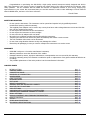
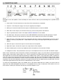
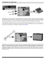
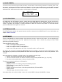
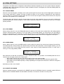
USER'S MANUAL
(Firmware rev. 1.01 – May 2014)
www.GenuineSoundware.com
GSi BURN USER'S MANUAL - Pag. 1/16
Congratulations on purchasing the GSi BURN, a high quality musical instrument entirely designed and built in
Italy. This instrument is the result of years of research and careful study of the effect produced by the famous Leslie
rotary speakers. We are confident that the BURN will become an important element of your set-up, bringing big
improvements to your sound. We recommend that you read this manual in order to take advantage of all the features
that the BURN offers, and store it for future reference.
The GSi Team.
SAFETY INFORMATION
–
–
–
–
–
–
–
–
–
–
Do not open the instrument. The instrument can be opened and repaired only by qualified personnel.
Unauthorized opening voids the warranty.
The supplied power adapter can be used in any country that has a mains voltage between 100 Vac and 240 Vac.
Use only the original power supply.
Do not expose the instrument to rain and moisture.
Do not expose the instrument to direct sunlight.
Do not touch the AC adapter with wet hands.
Be careful not to infiltrate powders and liquids inside the instrument.
If liquids get inside the unit remove the power immediately and contact a service center.
The side ventilation holes must not be obstructed.
Do not clean using abrasive cleaners as they may damage the surface.
Please keep all packaging in case you need to transport the instrument to a service center.
WARRANTY
–
–
–
–
–
GSi BURN is subject to 12 months manufacturer's warranty.
Warranty extensions are at the discretion of the retailer.
Damages caused by misuse, improper maintenance or transportation are not covered by this warranty.
During the warranty period, the customer is entitled to repair or replacement of any parts considered defective at
no charge.
The possible replacement of the entire product is at the manufacturer's discretion.
CHAPTER INDEX
1.
2.
3.
4.
5.
6.
7.
8.
9.
10.
11.
12.
13.
14.
15.
16.
17.
18.
19.
20.
INTRODUCTION
CONTROL PANEL
CONNECTION PANEL
EXAMPLES OF CONNECTION
HOME SCREEN
LOCK FUNCTION
EXTERNAL MODE
EDIT MDOE
PRESET PARAMETERS
RENAME, SAVE OR INITIALIZE A PRESET
INPUT/OUTPUT FUNCTIONS
MIDI SETTINGS
ASSIGNING MIDI CONTINUOUS CONTROLLERS
MAPPING MIDI PROGRAM CHANGE VS. PRESET
PEDAL SETTINGS
DISPLAY CONTRAST AND FIRMWARE INFORMATION
REMOTE CONTROL
UTILITY
OTHER MIDI FUNCTIONS
TECHNICAL SPECIFICATIONS
Pag.
Pag.
Pag.
Pag.
Pag.
Pag.
Pag.
Pag.
Pag.
Pag.
Pag.
Pag.
Pag.
Pag.
Pag.
Pag.
Pag.
Pag.
Pag.
Pag.
3
3
4
5
6
6
6
6
7
10
10
11
12
12
13
14
14
15
15
16
GSi BURN USER'S MANUAL - Pag. 2/16
1. INTRODUCTION
GSi BURN is a digital simulator of the "rotary" effect as that of the famous rotary amplifiers from Leslie mod. 122 and 147
and similar, dedicated to electromagnetic organs and their simulators, but can also be used with modern keyboards as
well as electric guitars, and is also a versatile multi-effects with MIDI control. The presence of a MIDI interface, an
alphanumeric display and a non-volatile memory to save the preset make the BURN a tool that perfectly integrates with
any modern set-up for both live and the studio.
In order to simulate the famous "doppler" effect of the rotary speakers, the BURN takes advantage of a
powerful microprocessor that runs at 6,4 MIPS and processes the digital signal at a 24 bit resolution,
granting a clean sound and a dynamic range of well over 96 dB.
The distortion effect, much desired from musicians all over the world, is obtained by
means of a true vacuum tube and a special circuitry that recreates all the sonic
character of both the preamplifier and the final amplifier of a rotary speaker like the
famous Leslie 122 and Leslie 147.
2. CONTROL PANEL
The control panel of the BURN offers a backlit LCD display that shows all relevant informations about the use and the
editing of the instrument. The data is inserted by means of a rotary encoder and two buttons.
A) LCD display 16 characters on 2 lines. The backlight is turned on in standard usage. It turns off when the LOCK
mode is activated.
B) EXT/ALT Key: to activate the control from an external device connected to the REMOTE jack. The LED lights up
when the EXTERNAL function is activated.
C) EXIT/LOCK: Used to return to the previous page, exit a menu, or to activate the lock function. The LED lights up
when the LOCK mode is activated.
D) EDIT/ENTER Key: to enter the EDIT mode, confirm an action, enter a sub-menu. The LED lights up when you
enter EDIT mode, and blinks when you are about to enter the value of a parameter.
E) Rotary Encoder: To change the preset when you are on the HOME screen or to change the value of the
parameters when you are in EDIT mode.
GSi BURN USER'S MANUAL - Pag. 3/16
3. CONNECTION PANEL
All the connections are on the back side of the BURN. Make sure the unit is turned off before connecting any device.
Remember to turn the amplifier on last and always turn them off first in order to prevent damage due to possible electric
"bumps".
1. Power switch. Turn the instrument on only when all the connections are completed.
2. Socket for 12 Volt DC power supply. Use only the supplied power adapter.
3. MIDI input. Connect the cable from the output of a MIDI instrument to control the BURN.
4. MIDI THRU. At this output you will find an exact copy of the incoming data to the MIDI IN.
5. Input for optional remote control. See chapter REMOTE CONTROL for more details.
6. Left audio input. This input is connected to the TUBE OVERDRIVE circuit and to the DSP processor for signal
processing. Connect here the instrument to which you want to apply the sound effects of the BURN.
7.
Right audio input. Connect the output of an instrument with stereo outputs to take advantage of the True Stereo
Bypass, or turn the [I /O] RIGHT IN -> PASS THRU to send a copy of the input signal in this jack to the stereo
outputs.
8. Audio left output. Connect this output to the left channel of the amplifier.
9. Right audio output. Connect this output to the right channel of the amplifier.
10. Stereo headset jack to connect any headphones with an impedance of not less than 32 Ohms.
11. Headphones volume. This potentiometer acts only on the headphones and not on the LEFT and RIGHT outputs.
Either "active" instruments (such as keyboards, computer, electromagnetic organs, etc.) and "passive" (like electrified and
electric guitars, bass guitars, electric pianos, etc..) can be connected to the BURN audio input, the important is that the
input signal does not exceed the amplitude allowed by the BURN which is about 3 Vpp (Volt Peak to Peak), equivalent to
1.05 Vrms. Connect the instrument and adjust its volume until the red LED of the CLIP indicator lights up, then slightly
lower the volume of the instrument in order to reserve a threshold and prevent the occurrence of a digital CLIP as much
as possible. The CLIP LED indicates the presence of a signal overload in both the digital input and output paths. The level
of the input signal influences also the amount of tube distortion, if this is active.
To connect an electromagnetic organ to the BURN, such as the famous Hammond B3 or similar, you have to take an
output from the AO28 preamplifier and take it to an acceptable level by using an attenuator circuit similar to the one
shown below. Contact your technician and ask him to build an adapter for you.
GSi BURN USER'S MANUAL - Pag. 4/16
4. EXAMPLES OF CONNECTION
4.1. Connection of a Workstation keyboard.
The BURN offers a stereo audio input on two standard 1/4 inch jacks of type TS (Tip - Sleeve) but the signal used by the
processor and by the tube distortion is the left channel for the majority of effects. However, there are two standard
connectors just to allow you to connect keyboards with stereo output and take advantage of the True Stereo Bypass
when, during a performance, you want to use a stereo sound that does not need to be processed by the BURN.
A digital keyboard with MIDI output can be connected to the MIDI input of the BURN in order to control the Rotary speed
of the effects directly using the commands on the keyboard (for example, the modulation wheel, the sustain pedal, or
other controls on the panel). For more details, see Chapter MIDI SETTINGS.
4.2. Connection of an electric guitar.
The BURN is in the form-factor of a stomp-box exactly like all conventional effects for guitar or bass. The Rotary effect
algorithms are simulations of amplifiers that introduce colors and ambience typical of real amplifiers re-amplified for a PA
stage or recorded with microphones, therefore, it should not be connected to additional amplifiers, but with the BURN it
is possible to exclude the cabinet simulations and use the effect on a real amp. Other effects, however, allow you to
simulate static amplifiers in order to play guitars or organs in regular Hi-Fi stereo sets, Studio monitors or Live amps.
Finally, there are other effects such as chorus, phaser, delay, etc. that can be used just like any other stomp-box in an
existing effect chain.
GSi BURN USER'S MANUAL - Pag. 5/16
5. HOME SCREEN
The Home screen shows the preset number, its name, and the values of the following parameters: Tube Gain, Tube Level,
Parameter 1 and Parameter 2. This information is updated in real time when changing presets or when MIDI messages
are received that require modification. If the tube distortion is on, the symbol of the valve appears between the values
GAIN and LEVEL. Rotate the encoder knob to scroll through the 32 presets.
NO.
PRESET NAME
01: GSi BURN
0 100 100
24
GAIN
LEVEL
PAR.1
PAR.2
6. LOCK FUNCTION
By holding down the EXIT/LOCK for about 2 seconds when the display shows the Home screen, you can put the unit in
Lock mode, that is, the encoder and the three buttons will be deactivated and the display backlight is off. The unit
remains in operation and continues to receive commands via MIDI and from the three pedals. To unlock the controls
press the EXIT/LOCK button again for 2 seconds.
7. EXTERNAL MODE
The EXT/ALT button activates the optional remote controller connected to the REMOTE jack. For more information, see
chapter REMOTE CONTROL.
8. EDIT MODE
Press the EDIT/ENTER key when the display shows the Home screen to enter the EDIT mode. The corresponding LED
turns on. In this mode you can set all the parameters for the preset, save or initialize the preset, and set all MIDI
parameters and global parameters.
There are different levels of EDIT:
– Level 1: scroll pages, display parameters
– Level 2: to change the value of a parameter
– Level 3: to change the value of a sub-parameter
– Level 4: only a few pages access this level, it is generally used to confirm an action
We move to the next level by pressing the EDIT/ENTER and you go back to a previous level by pressing EXIT / LOCK.
While adjusting a parameter, the EDIT/ENTER LED flashes and a cursor appears under the value of the parameter to be
changed.
Each page displays a parameter in the EDIT mode. The parameters can be of type:
1. numeric: you choose a value from 0 to 127 using the encoder
2. exclusive: alternate between two different selections using the EDIT/ENTER button (eg.: ON / OFF)
3. list: there can be multiple values to choose using the encoder
The pages are ordered according to the following list:
– Preset parameters
– [PRESET] functions for renaming, saving and initializing a preset
– [I/O] functions for settings about the connections
– [MIDI] settings
– [PEDAL] settings for the function of the three pedals BYPASS, STOP and SPEED
– Display contrast
– Information page, shows the firmware version
Some pages allow you to edit more data at once, such as the [MIDI] PC Map and the [MIDI] CC Assign.
GSi BURN USER'S MANUAL - Pag. 6/16
9. PRESET PARAMETERS
The preset parameters may vary depending on the type of effect in use, for example the ROTARY effects show some
parameters that do not appear in other effects.
The first page that is displayed by entering the EDIT mode is the choice of the effect. Every time an effect is changed,
parameters called Parameter 1, Parameter 2 and Parameter 3 are recalled with their default values according to the
current effect. The Parameter 3, when available, can be controlled via an expression pedal connected to the REMOTE.
See chapter REMOTE CONTROL for more details.
SET EFFECT: #
1
ROTARY: ROCK 147
9.1. ROTARY SPEAKER EFFECTS
The BURN offers a variety of Rotary effects plus other effects of different nature. The effects from no. 1 to n. 9 are
simulations of Rotary Speaker dedicated mostly to the sound of the electromagnetic organ. All these effects have in
common the reverb level at Parameter 2 and the balance between high and low at Parameter 1, with the exception of the
first effect lets you adjust only the volume of the horn. The differences between one simulation and the other mostly
concerns the greater or lesser presence of cabinet resonances, the spread of the Doppler effect in the stereo image, the
proximity effect of the horn and bass rotor with respect to virtual microphones, and other aspects that are not adjustable
through the editing parameters.
Effects from no. 10 to no. 12 are Rotary Speaker simulations dedicated to the sound of the guitar. The n. 12 called
VARISPEED allows to adjust the speed of the rotor directly way via an expression pedal connected to the REMOTE jack.
NOTE: Remember to activate the EXT/ALT button in order to use the accessory connected to the REMOTE jack.
The table below shows a list of the Rotary effects, the parameters associated with them and a general description of each
single effect.
#
EFFECT NAME
PARAM 1
PARAM 2
DESCRIPTION
1
ROTARY: ROCK 147
Horn Level
Reverb
Rotary model 147 with standard miking at 90° around the fulcrum
of the horn
2
ROTARY: JAZZ 122
Horn Level
Reverb
Rotary model 122 with standard miking at 90° around the fulcrum
of the horn
3
ROTARY: DISTANT
Balance
Reverb
Rotary with distant AB miking
4
ROTARY: CLOSER
Balance
Reverb
Rotary with close AB miking
5
ROTARY: XY MIKES
Balance
Reverb
Rotary with XY miking in front of the horn
6
ROTARY: ROCK 1
Balance
Reverb
Rotary with more cabinet presence
7
ROTARY: ROCK 2
Balance
Reverb
Rotary with miking at 180° around the horn
8
ROTARY: MONO
Balance
Reverb
Monaural Rotary, same signal at both outputs
9
ROTARY: SPLIT
Balance
Reverb
Rotary split: Bass at Left output, Trebles at Right output
10 AMP: MODEL 16
Mid. Freq.
Reverb
Rotary for guitar with single vertical rotor
11 AMP: RA-200
Balance
Reverb
Rotary for guitar with three rotating horns
GSi BURN USER'S MANUAL - Pag. 7/16
9.2. OTHER AMPLIFIER SIMULATORS AND MODULATION EFFECTS
Effects from no. 12 to no. 23 do not make use of the pedals STOP and SPEED. They activate the Parameter 3 which is
controllable through the external accessory connected to the REMOTE jack.
#
EFFECT NAME
PARAM 1
PARAM 2
PARAM 3
DESCRIPTION
12 AMP: VARISPEED
Mid. Freq.
Reverb
Rotary Speed Rotary for guitar with continuous speed control
13 AMP: STACK
Mid. Freq.
Mid. Gain
Reverb
Stacked amp for guitar
14 AMP: COMBO
Mid. Freq.
Mid. Gain
Reverb
Combo amp for guitar
15 EP: PHA+PAN+REV
Panner Rate
Reverb
Phaser
Effect for electric piano: auto-panner + phaser + reverb¹
16 EP: PHA+AMP+CHO
Brilliance
Reverb
Phaser
Effect for electric piano: phaser + amp + chorus¹
17 FX: ANALOG ECHO
Feedback
Mix Dry/Wet
Echo Time
Simulation of an analog echo with self oscillation capability
18 FX: PING DELAY
Delay Time
Feedback
Mix Dry/Wet
Ping-pong delay
19 FX: STEREOPHASER
Feedback
Reverb
LFO Speed
Stereo Phaser with 3 stages per channel
20 FX: STEREOCHORUS
LFO Depth
Reverb
LFO Speed
Stereo Chorus with 6 voices per channel
21 FX: WAH WAH
LFO Speed
Reverb
Manual Wah
Wah Wah with auto-LFO or pedal control²
22 FX: RING MOD.
SQR <-> SIN Reverb
LFO Speed
Ring Modulator
23 FX: STEP-FILTER
Step Speed
Filter Speed
Squared tremolo + modulated low-pass filter
Reverb
Note:
1. Effects no. 15 and no. 16: to activate the Phaser, Parameter 3 must be major than 12.
2. Effect no. 21: in order to control the Wah Wah via the optional expression pedal, the parameter LFO Speed must
be set to zero.
9.3. REVERB AND UTILITY EFFECTS
#
EFFECT
PARAM 1
PARAM 2
DESCRIPTION
24 REVERB: MONO MIX Dry Level
Reverb
Only reverb, dry inputs Left + Right are summed together
25 REVERB: STEREO
Dry Level
Reverb
Only reverb, dry inputs Left e Right stay independent
26 UTIL: PASS THRU
None
None
Digital bypass, allows the use of the sole tube distortion without
adding any more effects
27 UTIL: MUTE
None
None
MUTE, no audio output
Effects of no. 24 and no. 25 offer only the reverb effect and offer separate controls for the dry signal and the sound the
reverb. The term MONO MIX indicates that the signals from the left and right inputs are summed to create a single mono
dry signal that will be routed to both the left and right outputs. Conversely, the term STEREO indicates that the signals
coming from the Left and Right inputs will be routed to the respective outputs.
The effects of no. 26 and no. 27 can be used under special conditions, especially when the BURN is connected via MIDI
to other equipment. See chapter UTILITY for more details.
GSi BURN USER'S MANUAL - Pag. 8/16
Preset parameters are organized according to the following table:
REAL-TIME
PARAMETERS
VALUE
NOTE
NON REAL-TIME
PARAMETERS
VALUE
Tube Overdrive Switch
On - Off
Horn Slow Speed
Unplug, Slow, Normal, Fast
Tube Overdrive Gain
0 - 127
Horn Fast Speed
Unplug, Slow, Normal, Fast
Tube Overdrive Level
0 - 127
Bass Slow Speed
Unplug, Slow, Normal, Fast
Parameter 1
0 - 127
Varies based on the effect
Bass Fast Speed
Unplug, Slow, Normal, Fast
Parameter 2
0 - 127
Varies based on the effect
Horn Ramp Up
Slow, Normal, Fast
Parameter 3
0 - 127
Varies based on the effect
Horn Ramp Down
Slow, Normal, Fast
Bass Ramp Up
Slow, Normal, Fast
Bass Ramp Down
Slow, Normal, Fast
Freq. Mod. Amount
Less, Normal, More
Crossover Cutoff
Lower, Normal, Higher
Horn Resonance
Off, Type 1, Type 2, Type 3
Horn Timbre
Dark, Normal, Open, Bright
Reverb Length
Room, Studio, Hall, Church
Reverb Tone
Dark, Normal, Bright
Reverb Gain
OFF, -3 dB, Normal, +3 dB
Parameter 3 is used only by some effects. Parameters Reverb Length, Reverb Tone and Reverb Gain are copmmon to all
effects. The reverb is present on all effects and some of them don't allow it to be adjusted. Generally, the reverb is placed
post-effect, but there could be exceptions for some of the effects.
9.4. DETAILS ABOUT THE NON REAL-TIME PARAMETERS
–
–
–
–
HORN SLOW SPEED: horn speed when in SLOW, Slow (0,65 Hz), Normal (0,77 Hz) and Fast (0,93 Hz).
HORN FAST SPEED: horn speed when in FAST, Slow (6,3 Hz), Normal (6,8 Hz) and Fast (7,6 Hz).
BASS SLOW SPEED: bass rotor speed when in SLOW, Slow (0,62 Hz), Normal (0,72 Hz) and Fast (0,92 Hz).
BASS FAST SPEED: bass rotor speed when in FAST, Slow (5,8 Hz), Normal (6,4 Hz) and Fast (7,2 Hz).
The speed of the rotors are equivalent to those of a real Leslie 122 or 147, and reflect the possibilities given by the use of
various pulleys. For all the speeds you have one further choice, called UNPLUG, which completely disconnects the engine
and stops the rotation. For example, to get the famous "Memphis Sound" (in which only the horn is connected to the
motors and the bass rotor is always stopped), you must set both BASS SLOW SPEED and BASS FAST SPEED on UNPLUG.
–
–
–
–
HORN RAMP UP: the average time that the horn takes to transistion from Slow to Fast.
HORN RAMP DOWN: the average time that the horn takes to transistion from from Fast to Slow.
BASS RAMP UP: the average time that the bass rotor takes to transistion from Slow to Fast.
BASS RAMP DOWN: the average time that the bass rotor takes to transistion from Fast to Slow.
When the transistion is Fast to Stop or from Stop to Fast, the acceleration and deceleration times are slightly longer.
These times correspond to those of a real Leslie 122 or 147 when they are set to Normal. However, it is possible to
choose times slower or faster according to your preference.
–
–
–
–
FREQ. MOD. AMOUNT: sets the amount of frequency modulation of the Doppler effect. For some algorithms, this
setting also modifies on the amplitude modulation (the proximity effect of the horn in front of the microphones).
This parameter only affects the horn.
CROSSOVER CUTOFF: sets the cutoff frequency of the crossover that separates the basses from the trebles. It is
normally around 800 Hz, but two other choices are possible which set this frequency to 600 Hz or 1000 Hz.
HORN RESONANCE: sets the type of resonance created by the plastic horn of a rotating speaker, three different
types are available (Type 2 is equivalent to a Leslie 122 or 147) or you can turn it off.
HORN TIMBRE: changes the timbre of the horn with four different choices.
GSi BURN USER'S MANUAL - Pag. 9/16
10. RENAME, SAVE OR INITIALIZE A PRESET
Each preset can have an alphanumeric name up to a maximum of 12 characters. To assign a name to a preset, go to the
[PRESET] NAME page. Press EDIT/ENTER to show the cursor, turn the encoder to position the cursor underneath a
character to be changed. Press EDIT/ENTER to change the character. The cursor flashes. Turn the encoder to select the
character. To delete a character, turn the encoder clockwise until the character disappears (or appears a space).
[PRESET] NAME
01: GSi BURN_
Next page allows to save the preset to one of the 32 available memory locations.
[PRESET] WRITE
To position...12
Press the EDIT/ENTER button and turn the encoder to select the memory location. Press EDIT/ENTER again to to save.
It's possible to initialize the current preset with the default settings. Move to the [PRESET] INIT page and confirm by
pressing the EDIT/ENTER. Caution: This operation will overwrite the current preset and can not be undone.
[PRESET] INIT
Are you sure?
11. INPUT/OUTPUT FUNCTIONS
[I/O] RIGHT IN
PASS THRU
[I/O] OUT BOOST
100%
The audio input used to bring the signal to the DSP processor is LEFT/MONO, while the RIGHT input remains free in case
you want to connect an instrument with stereo output and take advantage of both channels when you are in BYPASS
mode, or you might want to use the RIGHT input for connecting an audio source to listen DRY in addition to the signal
from the BURN. In this case, set the parameter [I /O] RIGHT IN to PASS THRU.
In the example shown here, a Crumar Mojo is connected to the
LEFT/MONO input of the BURN in order to to use the Rotary
effect on the sound of the organ, and an mp3 music player or
any smartphone can be connected to the RIGHT input. By
activating the I/O RIGHT INPUT PASS THRU, the audio coming
from the mp3 player is mixed with the organ sound. By
connecting a good stereo headphone directly to the BURN you
can practice playing along with a backing track without
disturbing the neighborhood.
In case the input signal level is too weak or it is too hot to overload the DSP and needs to be reduced, it is possible to
compensate the difference between the input and the output level by adjusting the value of the page [I/O] OUT BOOST
up to a maximum of 195%, which corresponds to nearly +3 dB (loudness almost doubled). This function works only
when the page [I/O] RIGHT IN is set on OFF.
GSi BURN USER'S MANUAL - Pag. 10/16
12. MIDI SETTINGS
The BURN allows a detailed and customizable MIDI control in order to meet multiple needs. It is possible to control all
real-time parameters via MIDI, it's possible to recall presets and, most importantly, it's possible to control the Rotary
speeds via MIDI commands.
The first page of the MIDI settings allows to set the receive MIDI Channel. The range is 1 to 16 or OMNI, that means
that incoming events won't take the channel into consideration. Default setting is channel 1.
[MIDI] CHANNEL
888888888888Omni
To control the Rotary speeds it's possible to choose between one of the pre-set control sets or to create a custom control
set. Go to the page [MIDI] SPEED CTR to choose a Speed Control set.
[MIDI] SPEED CTR
GENERIC CC # 1
The following table gives details about the factory pre-set control sets.
GENERIC CC # 1
Uses CC#1 (Mod.Wheel) for 0-32 = SLOW; 33-95 = STOP; 96-127 = FAST
CRUMAR MOJO
Compatible with the commands of organs Crumar MOJO and Hamichord
NORD ELECTRO 3/4
Compatible with the commands of the keyboards Nord Electro 3 and 4
NORD C1/C2
Compatible with the commands of organs Nord C1, C2 and C2d
NORD STAGE 2
Compatible with the commands of the Nord Stage 2
KORG CX3/BX3
Compatible with the commands of organs Korg series CX3 and BX3
NUMA ORGAN/KeyB
Compatible with the commands of organs Studiologic Numa Organ and DLQ KeyB Duo/Solo
VISCOUNT DB5/DB3
Compatible with the commands of organs Viscount/Oberheim DB5 and DB3
HAMMOND SK1/SK2
Compatible with the commands of organs Hammond-Suzuki series SK1 and SK2
HAMMOND XK3/XK3c
Compatible with the commands of organs Hammond-Suzuki series XK3 and XK3c
KRONOS CC#80/81
Compatibile with the side keys of the Korg Kronos
PITCH/CC#1 JS
Uses the pitch bender for SLOW/FAST and the Mod. Wheel for RUN/STOP
USER DEFINED
Uses custom messages (explained later in this manual)
When the control set is USER DEFINED, it's possible to decide whether the commands must be of type "Latched" or
"Temporary". This same setting is applied to the optional accessory connected to the REMOTE jack.
[MIDI] SPEED TYP
Latched
Once the Control Change numbers have been assigned to the controls SLOW/FAST and STOP/RUN, it's necessary to
verify with the sender device whether the values of the Control Change are kept (latched) or reset (temporary). For
example, if the external controller uses a push button to switch between SLOW and FAST, the unit could manage the
MIDI messages in two ways:
–
–
Temporary mode: button pushed = value 127; button released = value 0
Latched mode: every time the button is pushed the value alternates between 0 and 127
According to the criteria used by the external MIDI unit, it's necessary to set this parameter the other way around,
because if, for example, the external controller uses Temporary controls, the BURN will have to latch them.
GSi BURN USER'S MANUAL - Pag. 11/16
13. ASSIGNING MIDI CONTINUOUS CONTROLLERS
It is possible to assign Continuous Controller numbers between 1 and 120 to the following parameters:
SHORT NAME
PARAMETER
DEFAULT CC
BYPASS
Stereo BYPASS
102
RUN/STOP
Rotary Speed RUN or STOP
N/A
SLOW/FAST
Rotary Speed SLOW or FAST
N/A
OVD SW
Tube Overdrive Toggle
103
OVD GAIN
Tube Overdrive Gain
111
OVD LEVEL
Tube Overdrive Level
112
PARAM 1
Parameter 1
91
PARAM 2
Parameter 2
93
PARAM 3
Parameter 3
N/A
Assigning a CC is very easy: press EDIT/ENTER to choose the parameter to which to assign the CC. While browsing the
parameter list, automatically the assigned CC number is shown. If no CC is assigned to a parameter, the dash symbol "-"
is shown; if the default CC number is assigned to a parameter, the letter D is shown after the number.
[MIDI] CC ASSIGN
OVD LEVEL > 109
Press again EDIT/ENTER to choose the CC number and rotate the encoder to select a number between 1 and 120. If a
MIDI device is connected to the BURN and sends Continuous Controller messages, the CC number shown on the display
is automatically updated with the last received CC number. To confirm the assignment, push EDIT/ENTER once again. To
cancel an assignment, for example in order to avoid conflicts with other MIDI devices in the chain, rotate the encoder
fully counterclockwise until a dash symbol "-" is shown and confirm by pushing EDIT/ENTER.
14. MAPPING MIDI PROGRAM CHANGE VS. PRESETS
The BURN has 32 presets but the total number of Program Change numbers in the General MIDI system is 128, ranging
0 to 127. It is, therefore, possible to choose a PC number per each preset via the [MIDI] PC MAP page.
[MIDI] PC MAP
Preset:12 PC:114
Press EDIT/ENTER and rotate the encoder to choose a preset number between 0 and 31. Press EDIT/ENTER again to
shift to the next value and rotate the encoder choose a PC number to assign to the preset. By default, presets 0 to 31 are
assigned to the same Program Change numbers. If a PC number is assigned to more tha one preset, only the preset with
the lower PC number will be recalled.
It is possible to exclude the received Continuous Controller or Program Change messages in the case it is preferrable to
avoid that these would interfere with other devices in the MIDI chain. Go to the page [MIDI] CC RECV or [MIDI] PC RECV
and set the related function as Enabled or Disabled according to your preference.
[MIDI] CC RECV
Enabled
GSi BURN USER'S MANUAL - Pag. 12/16
15. PEDAL SETTINGS
The pedals on the BURN can be configured to take different behaviors depending on the user's needs. With the exception
of BYPASS pedal, which will always be used to enable or disable the Stereo True Bypass, the STOP and SPEED pedals can
also perform other functions.
15.1. BYPASS PEDAL
When the True Stereo Bypass is activated, the incoming audio signal found at the input Left and Right jacks is directly led
to the output jacks with no change. This type of bypass is known as "true" because it bypasses the entire electronic
circuit by means of a mechanical contact. When the unit is turned off, the bypass is always active because the relay that
takes care of its operation is in a resting state.
The bypass status will always be saved in presets along with all the other parameters, but you can choose whether this
must be recalled when a preset changes or must remain completely independent. To operate this choice, go to the page
[PEDAL] BYPASS.
[PEDAL] BYPASS
Global Setting
15.2. STOP PEDAL
When a Rotary effect is in use, the STOP pedal stops the rotation of the virtual rotors exactly like a real rotating speaker
would do with this function. However, if you do not want to use the stop position, you can choose to use this pedal to
activate or deactivate the tube distortion. To make that choice go to the page [PEDAL] STOP. When the STOP pedal is
assigned to Overdrive Switch, you can hold down the SPEED pedal for about one second to engage the STOP speed.
[PEDAL] STOP
Overdrive Switch
15.3. SPEED PEDAL
When a Rotary effect is in use, the SPEED pedal is used to switch the speed of the virtual rotors between slow and fast.
The selected speed is always saved in the presets along with all the other parameters. Like the Bypass function, you can
choose whether this is to be recalled from the presets or must remain a totally independent function. To make such a
choice, go to the page [PEDAL] SPEED.
[PEDAL] SPEED
Saved in presets
Each pedal has an LED that is switched on or off to indicate its status. The operation of the SPEED pedal LED can be
chosen at the next page, and can be of three types:
– FAST On/Off: the LED is lit when the speed is FAST, off when the speed is SLOW
– Anim & Stop: the LED flashes quickly or slowly depending on the speed, and stops when the speed is STOP
– Anim always: the LED flashes quickly or slowly depending on the speed and continues to flash even though the
speed is STOP
By default, the LED is set to On/Off.
15.4. PRESET UP & DOWN
When an optional accessory is connected to the REMOTE jack and the EXTERNAL function is activated, pedals STOP and
SPEED function as PRESET PRESET UP and DOWN to decrease or increase the number of current preset.
GSi BURN USER'S MANUAL - Pag. 13/16
16. DISPLAY CONTRAST AND FIRMWARE INFORMATION
To adjust the contrast of the LCD display of the BURN according to your preferred viewing angle, go to the page DISPLAY
CONTRAST and choose a value between 0 and 64. The default value is 32 and corresponds to an angle of about 80° with
respect to the display.
DISPLAY CONTRAST
VALUE:
32
The next page shows information about the firmware version.
FIRMWARE VERSION
v1.01 28-10-2013
The firmware of the BURN is upgradeable via MIDI by means of a simple utility made available by GSi for Windows and
OSX. Consult the site www.GenuineSoundware.com from time to time to verify the availability of a new update.
17. REMOTE CONTROL
The REMOTE jack on the rear panel of the BURN can accept a variety of optional accessories for remotely controlling the
speeds of the Rotary effects or for the control of the Parameter 3 of other effects. This jack is connected to an
analog/digital converter located inside the central microprocessor of the BURN and you can connect a two or three
position switch of type "half-moon", as those generally used for the vintage rotating speakers, or you can connect a
footswitch with one or two buttons, or an expression pedal with linear potentiometer of 10 Kohm.
The picture on the right shows the terminals respectively connected to the tip (Vcc), ring
(ADC) and the sleeve (Ground) of the jack. Between tip and ring there is a voltage of
about 3.3 Volts. Be careful to never cause a short circuit between these two terminals.
The ring of the jack is to be considered as the common contact for switching. It is
preferable to use the switches of type "break before make".
When the REMOTE jack is connected to an accessory used to switch between the SLOW,
FAST and STOP speeds of a Rotary effect, the commutations are also subject to the setting of the page [MIDI] SPEED
TYP, and may occur in two different ways depending on whether this is of type Temporary or Latched. For more clarity,
refer to the following table.
SPEED TYPE = Temporary
SPEED TYPE = Latched
SLOW = RING + SLEEVE
RING + TIP switches between SLOW and FAST
STOP = RING isolated
RING + SLEEVE switches between STOP and RUN
FAST = RING + TIP
-
This means that, in case you are connecting a pedal with two buttons, it is possible to use either "mechanically latched"
or "temporary" buttons. Once the connections are made correctly, you just have to set your choice on the [MIDI] SPEED
TYP. For example, if using temporary buttons, you must choose "Latched", and
vice versa.
If you are connecting an expression pedal to the REMOTE jack, you have to
make sure that it has a linear potentiometer of 10 Kohm, and that the
connection is made according to the diagram on the side, and precisely the two
ends of the resistive track must be connected to the sleeve and to the tip of the
jack, and the wiper must be connected to the ring of the jack.
When a Rotary effect is in use and an expression pedal is connected to the
REMOTE jack, the speeds correspond to the following positions: pedal down= SLOW, pedal up = FAST, pedal in middle
position = STOP.
GSi BURN USER'S MANUAL - Pag. 14/16
18. UTILITY
Among the many effect algorithms of the BURN there are two, at the end of the list, considered UTILITY. The first, called
PASS THRU, is a digital stereo bypass, it means that the stereo signal coming into the DSP processor is led to the outputs
with no change. This could be useful if you want to take advantage of just the tube distortion of the BURN, present only
at the left channel, without applying any other effects.
The second UTILITY effect is called MUTE and does nothing but mute the output. This could be useful in case you want
to mute an instrument through a foot pedal or a Program Change command sent via MIDI.
18.1. SHORTCUTS
There are some shortcuts that allow you to perform some operations faster. For example, to save a presets without
necessarily reaching the [PRESET] WRITE, just hold down the EDIT/ENTER button for at least 2 seconds. The preset will
be saved in the current location, overwriting the existing data.
When you change the value of a parameter, you can return to the original value of the preset by pressing once
EDIT/ENTER when you are in EDIT mode at level 2 (change of a parameter). For some global settings, such as the MIDI
channel, this operation calls the default value.
When some preset parameter has been changed and you return to the HOME screen without having first saved, the letter
E appears before the name to indicate that the preset has been modified but not saved.
18.2. FACTORY SETTINGS RECALL
It is possible to reset all the presets and all the global settings by returning the unit like just out of the factory. Turn the
unit off, press and hold the EDIT/ENTER button and simultaneously turn on the unit, do not release the button until the
operation is finished.
19. OTHER MIDI FUNCTIONS
The BURN is able to receive some MIDI System Exclusive messages in order to 0x00
directly control the parameters in real-time even if these are not assigned to 0x01
Continuous Controller numbers. The format of the SysEx string is as follows:
0x02
F0 08 45 1D xx yy F7
0x03
where xx = number of parameter and yy = value between 00 and 7F.
0x04
Parameter numbers are listed here.
Tube Gain
Tube Level
Parameter 1
Parameter 2
Parameter 3
In addition, you can send a string containing all the data related to a preset. The correct reception of a string preset by
the BURN overwrites the required preset number. The total length of the string must be of 70 bytes, of which the first 4
bytes are for the header, 1 byte is the number of preset, 64 bytes are the data of the preset, the last byte closes the
Sysex strings. The format is as follows:
PART NAME
PART LENGTH CONTENTS
HEADER
4 bytes
F0 08 45 1A
PRESET NUMBER
1 byte
00
PRESET NAME
12 bytes
49 6e 69 74 20 50 72 65 73 65 74 20
PARAMETERS
23 bytes
00 00 00 64 64 18 00 00 02 02 02 02 01 01 01 01 01 01 02 01 02 01 02
FOOTER
29 bytes
00 00 00 00 00 00 00 00 00 00 00 00 00 00 00 00 00 00 00 00 00 00 00 00 00 00 00 00 00
END OF SYSEX
1 byte
F7
The example given in the table above will overwrite the preset 0 with the default parameters. The 23 bytes for the
parameters correspond to the values of the parameters in the order in which they appear on the display. Values outside
the allowable range will be ignored.
GSi BURN USER'S MANUAL - Pag. 15/16
20. TECHNICAL SPECIFICATIONS
–
–
–
–
–
–
–
–
0 dBFS equivalent (max level before digital clip)
Headphone out max load
Headphone out max power
Input impedance
Output impedance
S/N ratio
Power supply
Max current draw
3 Vpp (1,05 Vrms, 0,51 dBV @ 20 Kohm load)
32 ohm
20 dBm @ 32 ohm
1 Mohm
20 Kohm
>80 dBA
12 VDC
350 mA
All specifications are subject to change without notice.
Sign up for the newsletter to be informed of the BURN on future developments, original accessories,
offers and the release of new versions of the firmware. Send an email message to:
[email protected] and wait for the confirmation email.
Instrument designed and built in Italy by Guido Scognamiglio and Andrea Agnoletto - VM Connection. All rights reserved.
All trademarks used herein are the property of their respective owners. The trademarks Hammond and Leslie are the property of Hammond-Suzuki
Corporation and are used here only for reference purposes. Windows is a trademark of Microsoft Corporation. OSX is a trademark of Apple. Crumar is a
trademark owned by VM Connection.
V.M. Connection
Via Pascoli 44/A
30020 Quarto d'Altino - VE
Tel: 0039.0422.474.486
Fax: 0039.0422.825.706
www.crumar.it – www.GenuineSoundware.com
[email protected]
GSi BURN USER'S MANUAL - Pag. 16/16