1
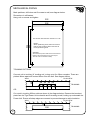
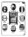
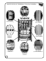
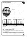
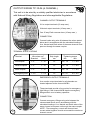
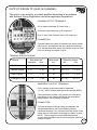
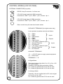
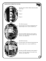
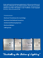
Mode Tiger
Dimmable Power Unit
MODE LIGHTING (UK) LIMITED
The Maltings, 63 High Street, Ware, Hertfordshire, SG12 9AD, England.
Tel: +44 (0) 1920 462121 e-mail: [email protected] Fax: +44 (0) 1920 466881
TIGER INSTALLATION MANUAL
TP-10-06 and TP-06-09
Page
1.
Contents
2.
Introduction
3.
Installation procedure
4.
Mechanical fixing
5.
Identification of terminals TP-10-06 (6 channel)
6.
Identification of terminals TP-06-09 (9 channel)
7.
Mains supply wiring
8.
Output wiring TP-10-06 (6 channel)
9.
Output wiring TP-06-09 (9 channel)
10.
Control wiring - low voltage
11.
Control module settings
12.
Power module functions
13.
Indicator identification
14.
Technical specification TP-10-06 (6 channel)
15.
Technical specification TP-06-09 (9 channel)
16.
Spares and Maintenance
17.
Circuit/Load schedule
Mode Lighting (UK) Limited.
The Maltings, 63 High Street, Ware, Herts, England. SG12 9AD.
Tel : +44 (0)1920 462121 Fax : +44 (0)1920 466881
e-mail: [email protected]
1
INTRODUCTION
"Reliability from Mode"
MODE POLICY: To create superior products and to provide our customers
with long term reliability, serviceability and value for money. The Company
does not make economies which are of short term benefit only.
FOUNDATION: Mode was established in 1970 as an Original Equipment
Manufacturer in Hertfordshire, England. Mode designs and manufacturers in
the U.K. Architectural Lighting Control Equipment, Electronic Transformers,
Cold Cathode (Neon) Convertors and many other Electronic Lighting
products. Mode is a subsidiary of a privately owned Holding Company known
as TCL and has four associated electronic companies who together trade as
"The Mode Group".
PREMISES: The Mode Group occupies well equipped factories, offices and
large warehouses in Ware and Hertford, having a commercial area of
2
10,000m . We are situated 40Km from London, 50Km from Heathrow Airport
and 20Km from Stansted Airport.
STAFF: The Mode Group employs more than 140 persons, including thirty
Managers, twenty Engineers and Technicians and over eighty Manufacturing
Staff. There are three Principal Directors and seven other Directors who
between them own all of the issued share capital of the Holding Company.
CLIENTS: The Mode Group has over 500 clients in over 30 countries.
Mode Lighting (UK) Limited.
2
The Maltings, 63 High Street, Ware, Herts, England. SG12 9AD.
Tel : +44 (0)1920 462121 Fax : +44 (0)1920 466881
e-mail: [email protected]
INSTALLATION PROCEDURE
1.
Remove all packaging.
2.
Read instructions and retain for future reference.
3.
Fit unit to wall and observe spacing instructions.
4.
Remove front plate and store in a safe place.
5.
Fit trunking (4" minimum) to desired option.
6.
Install all input supply wiring to National Wiring Regulations
and other applicable Regulations.
7.
Install all output load wiring to National Wiring Regulations
and other applicable Regulations.
8.
Install all low voltage control wiring.
9.
Set all switches and jumper links.
10.
Ensure that all wiring is tidy and that all ventilation grilles are
unobstructed.
11.
Switch on supply to unit.
12.
Test all loads are operating correctly.
13.
Set "start" address.
14.
Program operating system.
15.
Test operation.
16.
Re-fit front plate.
Mode Lighting (UK) Limited.
The Maltings, 63 High Street, Ware, Herts, England. SG12 9AD.
Tel : +44 (0)1920 462121 Fax : +44 (0)1920 466881
e-mail: [email protected]
3
MECHANICAL FIXING
Mark positions, drill holes and fit screws to wall, see diagram below.
Dimensions in millimetres.
Hang unit on screws and tighten.
322
302
534
452
Use screws with minimum size No.8 x 1 1/2"
NOTE :
When positioning holes, take into account
that the unit will drop 10mm lower due to
the keyhole fixing slots
WARNING:
Allow 300mm top and at least 40mm side clearance
between the side flanges and any other object.
This unit must be mounted vertically.
TRUNKING OPTIONS
Connect unit to trunking (4" trunking min.) using up to five 32mm couplers. These are
pitched 48mm apart and centred 62mm from the wall. See diagram below.
WALL
62
PLAN VIEW
48 48 48 48
TRUNKING
OR
Cut notch in trunking 250mm wide as shown in the diagram below. Remove the knockout
plate from the Tiger Power Unit underside and fit trunking to wall, butting up underneath the
Power Unit. Ensure all sharp edges are covered to prevent damage to cable insulation.
WALL
39
PLAN VIEW
250
4
TRUNKING
IDENTIFICATION OF TERMINALS TP-10-06 (6 CHANNEL)
PHASE INPUT NEONS
DMX / SCENARIO
INPUT TERMINALS
ANALOGUE INPUT /
OUTPUT TERMINALS
EMERGENCY
TERMINALS
AND MCBÌS
START ADDRESS
AND FUNCTION SWITCHES
CHANNEL OUTPUT
TERMINALS
MAINS INPUT
TERMINALS
5
IDENTIFICATION OF TERMINALS TP-06-09 (9 CHANNEL)
PHASE INPUT NEONS
DMX / SCENARIO
INPUT TERMINALS
ANALOGUE INPUT /
OUTPUT TERMINALS
EMERGENCY
TERMINALS
AND MCBÌS
START ADDRESS
AND FUNCTION SWITCHES
CHANNEL OUTPUT
TERMINALS
MAINS INPUT
TERMINALS
6
MAINS SUPPLY WIRING
This unit is to be wired by a suitably qualified electrician in accordance
with National Wiring Regulations and other applicable Regulations.
TERMINALS
Three Live phase input terminals (20 amp max.).
One Neutral input terminal (60 amp max.).
One Earth input terminal (60 amp max.).
TERMINAL SPECIFICATIONS
Terminal
Wire sizes mm2
Stranded
Solid
Strip length
mm
Tightening torque
Nm
lb/in
Phase 1
Phase 2
Phase 3
4 - 16
4 - 16
4 - 16
4 - 25
4 - 25
4 - 25
14
14
14
1.2 - 1.4
1.2 - 1.4
1.2 - 1.4
10.6 - 12.3
10.6 - 12.3
10.6 - 12.3
Neutral
10 - 35
10 - 50
17
2.8 - 3.0
21.8 - 26.1
Earth
10 - 35
10 - 50
17
2.8 - 3.0
21.8 - 26.1
CONNECTION
Connect three live input feeds using wire of between the values stated above and in
accordance with the calculated loadings. The live feeds do not have to be from different
phases. Any combination of phases is acceptable.
Connect Neutral feed using wire of between the values stated above and in accordance
with the calculated loadings.
Connect Earth using wire of between the values stated above and in accordance with the
calculated loadings.
7
OUTPUT WIRING TP-10-06 (6 CHANNEL)
This unit is to be wired by a suitably qualified electrician in accordance
with National Wiring Regulations and other applicable Regulations.
CHANNEL OUTPUT TERMINALS
6 Live output terminals (10 amp max.).
6 Neutral output terminals (10 amp max.).
One 15 way Earth common bars (10 amp max.).
CONNECTION
Connect loads using wire of between the values stated
below and in accordance with the calculated loadings.
Live, Neutral and Earth wires of the same channel must
pass out through the same coupler.
TERMINAL SPECIFICATIONS
Terminal
Wire sizes mm2
Stranded
Solid
Live outputs
1-6
1 - 10
12
0.8 - 1.0
7.1 - 8.9
Neutral outputs
1-6
1 - 10
12
0.8 - 1.0
7.1 - 8.9
Earth outputs
1-6
1 - 10
12
0.8 - 1.0
7.1 - 8.9
Emergency outs
1 - 2.5
1 - 2.5
10
0.5 - 0.7
4.4 - 6.2
Strip length
mm
Tightening torque
Nm
lb/in
EMERGENCY OUTPUT TERMINALS
Live monitor output terminals for all channels are
located adjacent to the channel MCB's.
These terminals provide a live monitor for emergency
light fittings. If the channel MCB trips the emergency
fittings switch over to battery operation.
CONNECTION
8
Connect emergency fittings using wire between the
values stated above and in accordance with the
calculated loadings. Live, Neutral and Earth wires of the
same channel must pass out through the same coupler.
NOTE : The emergency current and channel load
current added together should not exceed the maximum
channel current.
OUTPUT WIRING TP-06-09 (9 CHANNEL)
This unit is to be wired by a suitably qualified electrician in accordance
with National Wiring Regulations and other applicable Regulations.
CHANNEL OUTPUT TERMINALS
9 Live output terminals (6.6 amp max.).
9 Neutral output terminals (6.6 amp max.).
One 15 way Earth common bars (6.6 amp max.).
CONNECTION
Connect loads using wire of between the values stated
below and in accordance with the calculated loadings.
Live, Neutral and Earth wires of the same channel must
pass out through the same coupler.
TERMINAL SPECIFICATIONS
Terminal
Wire sizes mm2
Stranded
Solid
Live outputs
1-6
1 - 10
12
0.8 - 1.0
7.1 - 8.9
Neutral outputs
1-6
1 - 10
12
0.8 - 1.0
7.1 - 8.9
Earth outputs
1-6
1 - 10
12
0.8 - 1.0
7.1 - 8.9
Emergency outs
1 - 2.5
1 - 2.5
10
0.5 - 0.7
4.4 - 6.2
Strip length
mm
Tightening torque
Nm
lb/in
EMERGENCY OUTPUT TERMINALS
6 Live monitor output terminals for channels
1,3,4,6,7 and 9 located adjacent to the channel MCB's.
These terminals provide a live monitor for emergency
light fittings. If the channel MCB trips the emergency
fittings switch over to battery operation.
CONNECTION
Connect emergency fittings using wire between the
values stated above and in accordance with the
calculated loadings. Live, Neutral and Earth wires of the
same channel must pass out through the same coupler.
NOTE : The emergency current and channel load
current added together should not exceed the maximum
channel current.
9
CONTROL WIRING (LOW VOLTAGE)
EXTERNAL CONNECTORS (top plate)
RS-232 9 way D connector - for future use.
5 Pin XLR chassis socket for DMX connection.
Connections:- DMX+ = pin 3, DMX - = pin 2, Screen = pin 1.
5 Pin XLR chassis plug for DMX connection.
+
-
Connections:- DMX = pin 3, DMX = pin 2, Screen = pin 1.
25mm conduit entry for hard wired control cables.
DATA INPUT TERMINALS (for digital control only)
Lever operated screwless terminals as follows:D+
DSC
D+
DSC
5V
DT
0V
5V
DT
0V
=
=
=
=
=
=
=
=
=
=
=
=
DMX+
DMXDMX Screen
DMX+
DMXDMX Screen
+5V supply to Scenario plate
Scenario Data line
0V reference
+5V supply to Scenario plate
Scenario Data line
0V reference
}
}
Inputs
Outputs
}
}
Inputs
Outputs
AUXILIARY TERMINALS
15 = +15V DC output to supply remote equipment
A L = Alarm input
TERMINALS 1 - 18
In Digital Mode
These terminals provide either 0 to +6V or 0 to +10V
DC control signals.
Capable of sourcing 50µA and sinking 100mA.
For 6 channel type terminals 07-18 are not used.
For 9 channel type terminals 10-18 are not used.
In Analogue Mode
Terminals 1-9 to be supplied with a DC control signal
of 0 to +6V or 0 to +10V.
For 6 channel type terminals 07-18 are not used.
10
CONTROL MODULE SETTINGS
Display showing start address.
Scenario data indicator.
Data error indicator.
DMX data received indicator.
Push button increment 100's for start address.
Push button increment 10's for start address.
Push button increment 1's for start address.
For future use.
DIP switches - RIGHT=ON.
1 - 6 / 9 channels (6 = off ).
2 - Digital / Analogue ( Analogue = off ).
3 - 6V / 10V Operation ( 6V = off ).
4 - DMX / RS232 ( DMX = off ).
5 - Set DMX terminator, not used in Scenario systems.
6 - Tiger 120/60 (120 = off).
7 - Normal / Test (Normal = Off).
8 - Unlock / Lock (Unlock = Off).
}
NOTE - For Scenario operation switch 4 should be set to DMX. The processor will sense
that DMX is not present and will operate in Scenario mode. If a DMX signal is detected it will
override the Scenario data bus. The terminator switch should always be set to off for
Scenario installations.
Switch setting examples - the first two examples are the factory settings.
ON
ON
ON
ON
ON
ON
ON
ON
ON
2
ON
ON
1
8
ON
8
7
ON
7
6
ON
6
5
ON
5
4
ON
4
3
ON
3
2
ON
2
1
1
9 channel, Digital, 10V, DMX or Scenario, Not last in DMX line.
When in digital mode the 10V refers to the output voltage available for
driving ballasts etc..
6 channel, Digital, 10V, DMX or Scenario, Not last in DMX line.
ON
ON
ON
ON
ON
8
ON
ON
7
4
ON
6
3
ON
5
2
ON
4
1
3
9 channel, Analogue, 10V, DMX or Scenario, Not last in DMX line.
When in analogue mode the position of switch 4 is ignored. The 10V refers
to a voltage of 0-10V required to drive the channel between off and full on.
ON
ON
ON
ON
ON
ON
4
8
ON
3
7
ON
2
6
1
5
6 channel, Analogue, 6V, DMX or Scenario, Not last in DMX line.
ON
ON
ON
ON
5
ON
6
ON
7
ON
8
ON
ON
4
ON
8
3
ON
7
2
ON
6
1
5
6 channel, Digital, 10V, RS232, Last in DMX line.
9 channel, Digital, 10V, RS232, Last in DMX line.
Maximum number of channels for DMX operation is 512.
Maximum number of channels for Scenario operation is 99.
In the event of a DMX or Scenario error the last level received will be maintained.
Refer to Mirage Scenario programming guide for functions associated with the architectural
scene setting system.
11
POWER MODULE FUNCTIONS
TWIN MODULE
used in 6 channel model TP-10-06
Heatsink and mounting bracket
RFI noise suppression chokes
Channel mains feed indicators 2 (green)
User replaceable triac
Channel control signal indicators 2 (red)
Output pre heat adjustment control
Set switch point for switching channels
Set alarm enable for selected channel
Set a channel to switch or dim
Module full on test switch
TRIPLE MODULE
used in 9 channel model TP-06-09
Heatsink and mounting bracket
RFI noise suppression chokes
Channel mains feed indicators (green)
User replaceable triac
Channel control signal indicators (red)
Output pre heat adjustment control
Set switch point for switching channels
Set alarm enable for selected channel
Set a channel to switch or dim
Module full on test switch
12
INDICATOR IDENTIFICATION
The three neons shown indicate when the phase
input is live.
Phase 1
Phase 2
Phase 3
TP-10-06 (6 channel)
The two green neons shown indicate when the
channel input is live i.e. when the MCB is on.
The two red LED's indicate a control signal is
present. These still operate if the mains to the
module is not switched on.
TP-06-09 (9 channel)
The three green neons shown indicate when the
channel input is live i.e. when the MCB is on.
The three red LED's indicate a control signal is
present. These still operate if the mains to the
module is not switched on.
13
TECHNICAL SPECIFICATION TP-10-06 (6 CHANNEL)
POWER
SUPPLY
Voltage 230V AC nominal. (207V - 253V), 50Hz.
(110V 60Hz AC nominal available to order)
Single phase neutral and earth - three 20 amp live feeds.
Three phase neutral and earth Star configuration - 20 amp/phase.
(Three phase Delta configuration available to order)
Connection - hard wired to din rail mounting screw terminals.
TOTAL CURRENT 60 AMP.
DIMMING
OUTPUTS
Hard fired leading edge triac triggering.
Maximum load 10 amps per channel resistive, 9 amps inductive.
Minimum load 40 watts per channel (200 watts for fluorescent ballasts, when channel set to switch output).
Output connections hard wired :Live and Neutral outputs - din rail mounting screw terminals.
Earth outputs - brass earth common bar.
EMERGENCY
OUTPUTS
Six switched live outputs on channels 1,2,3,4,5, and 6.
These outputs will normally give full mains output and under fault
conditions which trip the channel circuit breaker give zero output.
The total current on these channels emergency + dimmed must not
exceed the maximum channel rating.
PROTECTION
Individual 10 amp Type C channel feed circuit breakers.
Green channel feed live indicators.
PSU module phase fuses 500mA anti-surge (3).
CONTROL
INPUTS
0-6V or 0-10V analogue, hard wired to screwless terminals.
Mirage Scenario data bus, hard wired to screwless terminals.
USITT DMX512 (1990), hard wired or via 5 pin XLR.
RS-232 interface via 9 pin D connector.
Alarm input - will set all alarm enabled channels to full output.
Control options set by DIP switches.
DC OUTPUTS
+5V at 50mA and +15V at 50mA hard wired to screwless terminals.
DIMENSIONS
`
FIXING CENTRES
Height
Width
Depth
Weight
Vertical = 452mm
WARNING -
ENVIRONMENT
14
Packed
600mm
400mm
240mm
11.3kgs
Unpacked
534mm
322mm
160mm
9.5kgs
Horizontal = 302mm
Allow 300mm top and at least 40mm side clearance
Between the side flanges and any other object.
This unit must be mounted vertically.
Operating temperature 0ºC to +40ºC.
Maximum case temperature +90žC.
TECHNICAL SPECIFICATION TP-06-09 (9 CHANNEL)
POWER
SUPPLY
Voltage 230V AC nominal. (207V - 253V), 50Hz.
(110V 60Hz AC nominal available to order)
Single phase neutral and earth - three 20 amp live feeds.
Three phase neutral and earth Star configuration - 20 amp/phase.
(Three phase Delta configuration available to order)
Connection - hard wired to din rail mounting screw terminals.
TOTAL CURRENT 60 AMP.
DIMMING
OUTPUTS
Hard fired leading edge triac triggering.
Maximum load 6.6 amps per channel resistive, 6 amps inductive.
Minimum load 40 watts per channel (200 watts for fluorescent
ballasts, when channel set to switch output).
Output connections hard wired :Live and Neutral outputs - din rail mounting screw terminals.
Earth outputs - brass earth common bars.
EMERGENCY
OUTPUTS
Six switched live outputs on channels 1,3,4,6,7 and 9.
These outputs will normally give full mains output and under fault
conditions which trip the channel circuit breaker give zero output.
The total current on these channels emergency + dimmed must not
exceed the maximum channel rating.
PROTECTION
Individual 8 amp Type C channel feed circuit breakers.
Green channel feed live indicators.
PSU module phase fuses 500mA anti-surge (3).
CONTROL
INPUTS
0-6V or 0-10V analogue, hard wired to screwless terminals.
Mirage Scenario data bus, hard wired to screwless terminals.
USITT DMX512 (1990), hard wired or via 5 pin XLR.
RS-232 interface via 9 pin D connector.
Alarm input - will set all alarm enabled channels to full output.
Control options set by DIP switches.
DC OUTPUTS
+5V at 50mA and +15V at 50mA hard wired to screwless terminals.
DIMENSIONS
Height
Width
Depth
Weight
FIXING CENTRES
Packed
600mm
400mm
240mm
12.3kgs
Vertical = 452mm
WARNING -
Unpacked
534mm
322mm
160mm
10.5kgs
Horizontal = 302mm
Allow 300mm top and at least 40mm side clearance
Between the side flanges and any other object.
This unit must be mounted vertically.
ENVIRONMENT
Operating temperature 0ºC to +40ºC.
Maximum case temperature +90ºC.
STANDARDS
Complies with CE EMC and LVD requirements.
15
MAINTENANCE
Periodically inspect the wiring for damage.
Ensure the ventilation holes have not become covered or blocked with dust.
Check overall condition of unit.
SPARES
The following spare parts are available:Item
Reference
PSU Module
TP-120-PSU
Twin Module
TPM-210
Triple Module
TPM-306
Digital Module
TP-120-DCM
ASSOCIATED PRODUCTS
TP-10-12
Tiger Dimmable Power Unit 12 x 10A
TP-06-18
Tiger Dimmable Power Unit 18 x 6A
MS-00-12
Scenario Master Switch Plate
RS-00-06
Scenario Remote Switch Plate
RT-00-10
Scenario Remote 7-day Time Clock
Remote Dimmer Outstations - Rotary or Slider Control
Dimmable Electronic Transformers for low voltage Tungsten Halogen Lighting.
Dimmable Neon Convertors for Cold Cathode (Neon) Lighting.
For further information, please contact:-
Mode Lighting (UK) Limited.
16
The Maltings, 63 High Street, Ware, Herts, England. SG12 9AD.
Tel : +44 (0)1920 462121 Fax : +44 (0)1920 466881
e-mail: [email protected]
DS094a-V1.2
Mode Lighting (UK) Limited was established in 1970 as a manufacturer of
electronic componets for the lighting industry. Mode has an enviable
reputation for quality, reliability and customer service. The Mode Group
employs more than 140 people in over 10,000m2 of well equipped
factories, offices and warehouses.
Products include:Electronic Transformers for Low Voltage.
Electronic Cold Cathode Convertors.
Architectural Dimming Systems.
Electronic Ballasts.
LED Systems.
TP-10-12
TP-06-09
TP-06-18
TP-10-06