1
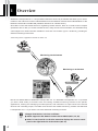
Versatile Monitoring Software
ENGLISH
User’s Manual
Introduction
Thank you for purchasing WebView Livescope MV Ver. 2.1 LE.
To take best advantage of this software, please first read this manual thoroughly.
After reading this manual, please store it in a safe place for future reference.
The latest product information is available at the following Website.
http://www.canon.com/webview/
Requests to Customers
The content of this manual may not be reproduced in its entirety or in part without prior
permission.
The content of this manual is subject to change without notice.
All possible measures have been taken to ensure that the content of this manual is accurate. If
you happen to notice errors, omissions or other faults, please contact Canon.
Irrespective of items above, Canon accepts no liability for any results arising from the operation
of this product.
Copyright Information
Please note that copyright laws prohibit the customer from using recorded videos and still pictures for any purpose
other than personal enjoyment without permission from the copyright holder.
Trademarks
● Canon and Canon logo are registered trademarks of Canon Inc.
● Microsoft, Windows, Windows NT, and Microsoft Internet Explorer are trademarks or registered trademarks of
Microsoft Corporation in the United States and other countries.
● Windows is legally recognized as Microsoft Windows Operating System.
● All other company or product names used in this manual are trademarks or registered trademarks of their
respective holders.
Icons Used in This Manual
c
Indicates notes of caution or limitations that must be kept in mind concerning operation. Be sure to
read these notes.
Note
e
Tip
2
Indicates supplemental explanations or references that are useful for operation.
Contents
Introduction .......................................................... 2
1. Overview .......................................................... 4
2. System Configuration ..................................... 5
Example of System Configuration ..................................... 5
Operating Environment ....................................................... 5
3. Installing .......................................................... 6
Prior to Installation... ........................................................... 6
Preparing the PC ............................................................................... 6
Installing the Camera Servers ........................................................... 6
Installation ............................................................................ 7
4. Registering the Cameras ............................... 8
Registering Cameras Using “Register Camera” .............. 8
Registering Cameras Using “Search Camera” ................. 9
5. Operating from the Menus ........................... 10
Detailed Settings ................................................................ 11
ENGLISH
Changing the Registration Order of Cameras ................................ 11
Setting Connection Protocols .......................................................... 11
6. Operating from the Toolbar .......................... 12
Main Operations ................................................................. 13
Switching Viewer Display Methods ................................................. 13
Switching Cameras being Viewed ................................................... 14
Reconnecting ................................................................................... 14
Taking/Saving Snapshots ................................................................ 14
Pausing Videos ................................................................................ 14
Displaying Full Screens ................................................................... 15
Viewing Connection Information ..................................................... 15
7. Operating the Cameras ................................ 16
Operating Cameras from the Camera Control Panel ..... 16
Operating a Camera with the Control Buttons ................................ 16
Controlling the Camera with Panorama .......................................... 17
Operating Cameras from the Viewer ............................... 17
8. Options .......................................................... 18
Setting the Video Relay ..................................................... 18
Setting HTTP ...................................................................... 18
9. Troubleshooting ............................................ 19
10. Error Messages ............................................. 20
3
1 Overview
WebView Livescope MV Ver. 2.1 LE (hereafter referred to as MV LE) is software that allows you to use an
Intranet or the Internet to monitor video distributed from the Network Camera Server VB150/VB101 or the
Network Camera VB-C10/VB-C10R (hereafter referred to as “camera server”).
Since MV LE uses the wizard format for registering camera servers, there is no need to learn complex
operations. MV LE lets you access camera servers, freely remote control cameras, and simultaneously
view images from camera servers installed in more than one location (up to 4 locations), providing an
efficient monitoring environment.
*When using VB101, upgrade the firmware to version 3.0.
VC-C4
COMMUNICAT
f:4-64mm ION CAMERA
1:1.4-2.8
Network Camera Server
Monitoring via the Internet
INT
E RNET
Monitoring on an Intranet
Network Camera
MV LE is a limited edition of WebView Livescope MV Ver. 2.1. WebView Livescope MV Ver. 2.1 provides
you with a wide variety of functions such as creating versatile monitoring screens to suit specific
applications, viewing and managing recorded pictures, and notification of input events from external
devices and controlling output, to enable more efficient and reliable monitoring. Please use WebView
Livescope MV Ver. 2.1 if you wish to use more advanced monitoring functions.
e
Tip
Changes from MV Ver. 2.0 LE are as follows:
→ P.5, 13, 18).
● Added support for the Network Camera Server VB150 (→
● Added “Control on Side” to the View menu that displays the camera control
→ P.13).
panel on the right hand side of the window (→
4
2 System Configuration
MV LE connects to camera servers using TCP/IP protocol. Connections can be made via the Internet or an
Intranet.
Example of System Configuration
LAN
Distributes
video and
picture data
ET
HE
E
RN
T
VC-C4
VC-C4R
Router
VB101
ISDN Line
Monitoring
VB-C10
MV LE
Router
Monitoring
via Internet is
also possible
Controls camera angle,
zoom, etc., and monitors
camera images
ENGLISH
Monitoring via ISDN line
Monitoring
MV LE
INTERNET
VB150
VC-C4
Controls camera angle,
zoom, etc., and monitors
camera images
NU-700
Operating Environment
CPU
Operating System
Web Browser
Memory
Hard Disk
Monitor
Pentium III 600 MHz or better
Windows Me/Windows 2000 (Service Pack 1 or later)/Windows XP
Internet Explorer 5.0 or later required
128 MB or better
Available space of 20 MB or better
XGA (1024 × 768) or better with high-resolution 16-bit color display or better
5
3 Installing
Prior to Installation...
Before installing MV LE, be sure that the PC in which it is to be installed and the camera servers satisfy
the conditions described below.
Preparing the PC
Check that the PC where MV LE is to be installed satisfies
the operating environment of MV LE(→
→ P.5). Be sure to set
the screen resolution to XGA (1024 × 768) or higher.
Display Properties
c
Note
If your screen resolution is set to XGA, use the “Control on Side” mode for the
→ P.13).
camera control panel display (→
Installing the Camera Servers
If the VB-C10/VB-C10R or VB150 is being used, there is no need to upgrade the firmware.
However, if the VB101 is being used, check to be sure that the firmware version is 3.0 or later. The
firmware is available for free at the following.
URL:http://www.canon.com/webview/
Check to be sure the camera server has been correctly installed and that the initial settings
(network settings) have been made. Then connect to the network.
Please refer to the manual supplied with the camera server for procedures on how to install and set
the camera server.
c
Note
The camera server’s “Maximum Number of Clients” setting must be set to 4
or more for the VB150 (or VB101). To make settings, use the setting page on
the camera server. While factory default settings meet the above
requirements, the settings must be checked if any changes are made.
6
Installation
When you load the WebView Livescope MV LE installer
1
CD-ROM, the installer automatically starts and the
installation process begins. If it does not start, in
Explorer, double-click “Setup.exe” on the CD-ROM and
click Next to proceed with the installation.
Enter the Serial number and click Next. The Serial
2
number is indicated on the seal attached outside the
software package.
A screen appears where you can specify a folder in which
3
MV LE is to be installed.
ENGLISH
To specify a folder other than the one indicated, click
Browse and select the folder you want.
When the folder has been specified, click Next.
Specify a name to be registered in the Program menu
4
under the Start menu, then click Next.
Check the items you have specified and selected thus far,
5
then click Next. The installation will be performed by
copying files and setting the registry.
When installation is complete, click Finish to exit the
installer.
e
Tip
If you are upgrading MV from Ver. 2.0 LE, the information on registered
cameras can be used with Ver. 2.1.
7
4 Registering the Cameras
Cameras must be registered in order to monitor images from them with MV LE. There are two ways to
register a camera: Using “Register Camera” in which the network address of a camera server is entered
manually, and “Search Camera” in which camera servers connected to the network are automatically
searched and detected cameras are registered.
First, double-click the desktop icon, or in the Start menu, choose
[Program]-[WebView Livescope]-[MV 2.1]-[LE Viewer], to start up
MV LE.
Choose Register Camera in the Operation menu. The Camera
Registration dialog box appears.
Up to 4 cameras can be registered. Registration is possible from
more than one camera server.
Registering Cameras Using “Register Camera”
If you know the IP address or the host name of the camera server, you can register the cameras which are
connected to the camera server by entering these items.
8
1
Click the Register Camera button to start up the Register Camera
Wizard.
2
In the Camera server address field, enter the IP address or the
host name of the camera server.
The default HTTP port No. that was set as an option (→ P.18)
appears in the HTTP port field. The HTTP port No. is usually 80,
but if another value is preferred, enter that in the HTTP port field.
Click Next.
3
When the Administration Account dialog box appears, enter the
Administrator ID and Password that were set in the camera
server.
Click OK.
4
Communication with the camera server occurs, and cameras that
can be registered are displayed. Select the cameras you want to
register, then click Finish.
5
Make sure that the camera you just registered appears in the
Registered cameras list.
To register more than one camera from a different camera server,
repeat the procedure from step 1 .
When you click OK, images from the registered camera can be
viewed.
Registering Cameras Using “Search Camera”
If you do not know the IP address of the camera server, you can search camera servers connected to
the network and register a camera from among the camera servers that are detected. Since it is
possible to detect only camera servers on the same LAN, for other camera servers, please use the
1
Click the Search Camera button.
2
Click Next. The camera servers connected to the network are
ENGLISH
Register Camera registration procedure.
automatically detected.
*If HTTP port other than 80 is used, the Search Camera feature
will only be available with the VB150. For other camera servers,
please use the Register Camera registration procedure
described on page 8.
3
The detected camera servers and the cameras that can be
registered are displayed. Select the camera to be registered. If
you select a camera server, all cameras connected to that server
are selected. When a selection is made, the Administration
Account dialog box appears where you must enter the
Administrator ID and Password that are set in the camera server.
Then click Finish.
4
Make sure that the camera you just registered appears in the
Registered cameras list.
When you click OK, images from the registered camera can be
viewed.
9
5 Operating from the Menus
Menu Bar
This chapter describes operating procedures
using the menus.
Menu Bar
Operation menu
“Register Camera”
Lets you register camera servers or change camera orders.
“Option”
Lets you set Video Relay or set the HTTP Port and HTTP Proxy.
“Exit”
Exits MV LE.
View menu
“Toolbar”
Shows/Hides the toolbar.
“4 Viewers/1 Viewer (Large)/1 Viewer (Normal)”
Switches the viewer display among 3 options: 4 viewers, 1 viewer (large),
and 1 viewer (normal).
“Control at Bottom/Control on Side”
Switches the camera control panel display between “Control at Bottom” and
“Control on Side”.
Viewer menu
“Camera Control Right”
Acquires camera control privileges.
“Reconnect”
Reconnects to the camera server when the connection is cut.
“Release Selection”
Releases a viewer selection.
“Snapshot”
Takes a snapshot.
“Pause/Resume”
Pauses and resumes a video.
“Full Screen”
Displays the full screen of an image. Press ESC to return to the original
screen display.
“Network Information”
Shows information about the connection to the camera server.
10
Detailed Settings
Changing the Registration Order of Cameras
An order is set for camera registrations. The position of viewers in which images are displayed and
the order of video relays are specified according to this order. The order can be changed after
registrations.
The camera registration order and the viewers that follow it are shown below. This applies only
during 4 Viewer display.
Registration numbers
(order) follow the viewer
ENGLISH
positions.
From the Operation menu choose Register Camera.
Click on a camera shown in the Registered cameras list
to select it, then click the Up or Down button to change
the position of the camera in the order.
When you have finished making changes in the order,
click OK.
Setting Connection Protocols
It is possible to set protocols for connections to the camera server.
To set a camera server connection protocol, select Auto, WV-TCP, or WV-HTTP. When Auto is
selected, the first connection attempt uses WV-TCP. If it fails, the connection is made using WVHTTP. Normally, Auto is selected, but if the connection passes through a firewall, select WV-HTTP.
In this case, please also set a proxy (→ P.18).
From the Operation menu choose Register Camera.
Click on a camera shown in the Registered Cameras list
to select it, then in the Protocol box, select Auto, WVTCP, or WV-HTTP.
When you have finished, click OK.
11
6 Operating from the Toolbar
Toolbar
This chapter describes operating procedures
using the toolbar
Toolbar
“4 Viewers”
Switches to 4 viewers display.
“1 Viewer (Large)”
Switches to 1 viewer (large) display.
“1 Viewer (Normal)”
Switches to 1 viewer (normal) display.
“Camera Switch Box”
Switches among cameras displayed in the viewer (during 1 Viewer display
only).
“Camera Control Right”
Acquires camera control privileges.
“Reconnect”
Reconnects to the camera server when the connection is cut.
“Snapshot”
Takes a snapshot.
“Pause/Resume”
Pauses and resumes a video.
“Full Screen”
Displays the full screen of an image. Press ESC to return to the original
screen display.
“Network Information”
Shows information about the connection to the camera server.
12
Main Operations
Switching Viewer Display Methods
There are three methods in which viewers can be displayed: 4 Viewers display, 1 Viewer (Large)
display, and 1 Viewer (Normal) display. Display can be switched by clicking on the 4 Viewers, 1
Viewer (Large), and the 1 Viewer (Normal) buttons on the toolbar. Choose the method that best
suits your needs.
Control at Bottom
4 Viewers display
1 Viewer (Large) display
1 Viewer (Normal)
display
ENGLISH
Control on Side
4 Viewers display
1 Viewer (Large) display
1 Viewer (Normal) display
e
Tip
When the VB150 is being used and the Video Input (→
→ VB150 User’s Manual
P.40) is set to Multiple, all four viewers can display video images at the same
time during 4 Viewers display.
13
Switching Cameras being Viewed
During 1 Viewer display, if more than one camera has been registered, the camera displayed in the
viewer can be switched. To switch cameras, click [2] in the Camera Switch box to select the camera
from the list. The order of the cameras shown in the list is the order in which the cameras were
registered.
Reconnecting
If for some reason a connection with the camera server is cut,
you can re-establish the connection without restarting MV LE
by clicking the Reconnect button on the toolbar.
Taking/Saving Snapshots
Snapshots of images in a selected viewer can be saved as an image file.
Click on the viewer containing the image you want to take
a snapshot of then click the Snapshot button on the
toolbar. When the “Save As...” dialog box appears, select
or enter a name for the file, the location where you would
like to save it, and click Save.
Image files are saved in JPEG format.
e
Tip
You can also use the Pause button to display a still video image and then
save it as a snapshot.
Pausing Videos
Video displayed in a selected viewer can be paused and displayed as a still picture. Click on the
viewer to select it, then click the Pause/Resume button on the toolbar. To return to normal video
display, click the Pause/Resume button again.
14
Operating from the Toolbar
Displaying Full Screens
Images in a selected viewer can be displayed on the entire screen. Click on the viewer to select it,
then click the Full Screen button on the toolbar.
When you click anywhere on the full screen display, the camera’s pan and tilt are controlled so that
that position becomes the center of the image. Press ESC to return to the original screen display.
When you right click on the full-screen display, a pop-up
menu appears. Choose Return to Normal to restore the
normal display.
If you choose Camera Control Panel, the Camera Control
Panel appears in a pop-up window which you can use to
control the camera.
Viewing Connection Information
ENGLISH
This command displays information about the connection
to the camera server. To view this information, click the
Network Information button on the toolbar.
●Frame rate
Shows the frame rate for the viewer.
●Image Size
Shows the size of the image being displayed.
●Video capture size
Shows the size of the video being captured by the
camera server.
●Compression type
Shows the image compression type being used.
●Video [WV-TCP]
Shows the IP address and Port No. of the camera
server if WV-TCP is being used for the video
transmission protocol.
●Camera control [WV-TCP]
Shows the IP address and Port No. of the camera
server if WV-TCP is being used for the camera control
protocol.
●Video/Camera control [WV-HTTP]
Shows the IP address and Port No. of the camera
server if WV-HTTP is being used for the protocol.
●HTTP proxy
Shows whether a HTTP proxy is being used (ON) or not
used (OFF).
●Local time
Shows the current time at the camera server.
15
7 Operating the Cameras
MV LE lets you freely control the cameras and monitor them. The cameras can be controlled from the
Camera Control Panel or on the viewer.
Operating Cameras from the Camera Control Panel
Operating a Camera with the Control Buttons
A camera can be freely controlled using the Pan, Tilt, and Zoom buttons. Backlight compensation
occurs when the Backlight Compensation button is turned on. Click this button again to turn
backlight compensation off.
AF/MF button
Displays a dialog box for switching between
Auto Focus and Manual Focus.
Speed button
Displays a dialog box for camera operation
speed.
Pan & Tilt/Home buttons
Pan and Tilt movements occur in the
direction of the arrows on the buttons.
Operation occurs when the button is
held down and stops when it is
released. The center button is the
Home button which, when clicked,
returns the camera to its home
position.
Backlight Compensation button
Turns backlight compensation on and off.
Backlight compensation is effective when
an image is dark due to backlight.
Zoom button
Lets you zoom in or zoom out. Zoom
occurs when the button is held down and
stops when it is released.
The Focus dialog box appears when the AF/MF button is
clicked.
• “Auto” indicates auto focus.
• “Auto (for domes)” is for the camera used in combination
with a camera dome. This ensures that focusing does
not occur on the wall of the dome.
• “Fixed at infinity” can be used when focusing is fixed on
infinity.
• With “Manual”, focusing is manually controlled by
holding down the Far or Near buttons.
The Speed dialog box appears when the Speed button is
clicked.
For the camera’s “Pan/Tilt Speed”, select Fast, Normal, or
Slow.
For the camera’s “Zoom Speed”, select Fast or Slow.
c
Note
If you are using the NU-700 (outdoor camera), use the Admin Viewer supplied
with the VB150 to make the following settings.
[Exposure], [ND Filter], [Wiper]
16
Controlling the Camera with Panorama
Pan, Tilt, and Zoom can be freely controlled
from the Panorama.
To change Pan and Tilt by clicking
When you click on a specific point on the panorama picture, the frame moves and the pan
and tilt change to make that point the center of the picture.
To change Pan and Tilt by dragging
When you move the frame on the panorama picture by dragging the inside of the frame, the
pan and tilt change accordingly.
To change Zoom ratio by dragging
Zoom ratio changes when you drag any side of the frame on the panorama picture to
change its shape.
To change Pan, Tilt, and Zoom ratio by dragging
Pan, tilt, and zoom ratio can all be changed when you create a new frame by dragging on
the panorama picture outside the existing frame.
Note
A panorama picture must first be created using the Panorama Creation Tool
supplied with the camera server before you use this feature.
ENGLISH
c
Operating Cameras from the Viewer
The Pan and Tilt of a camera can also be freely
controlled from the viewer. When you click on a
specific point on an image in the viewer, the
camera can be oriented to make that point the
center of the image.
You can click on the image to make that
point the center of the image.
c
Note
The Video Indicator on the viewer blinks green when
a video is being displayed and illuminates light blue
when a still picture is displayed.
17
8 Options
Option in the Operation menu lets you make Video Relay and HTTP settings.
Setting the Video Relay
Since only one viewer among a number of viewers can be used to display live video, Video Relay
automatically switches from more than one camera connected to a single camera server. The use of this
function can avoid clicking manually on individual viewers to switch video display.
From the Operation menu, choose Option. In the Interval field
of the Video Relay, enter a value between 5 and 30 to specify
the number of seconds for the auto display interval. Click OK
when finished.
e
Tip
● Video Relay operates constantly when a viewer is not selected.
● Video Relay is valid only during 4 Viewers display.
● Video Relay cannot be used with the VB-C10/VB-C10R.
→ VB150 User’s Manual
● When the VB150 is being used and the Video Input (→
P.40) is set to Multiple, all four viewers can display video images at the
same time during 4 Viewers display. Therefore, you do not need to set the
Video Relay.
● Video Relay may be unavailable when motion detection is enabled on the
VB150.
Setting HTTP
The HTTP Proxy and the HTTP port No. for connection to the camera server can be set in the HTTP
settings. These settings enable connection through a firewall.
From the Operation menu, choose
Option. In the “HTTP port for
communicating with the camera
server” field of the HTTP, enter the
HTTP port No. If you need the proxy
settings, click the HTTP Proxy button
to display the Proxy Settings window.
Enter the settings required for the
proxy. Click OK when finished.
18
9 Troubleshooting
■Cannot install
● When using Windows 2000, or Windows XP Professional, see if you have logged-in as an administrator.
■Cannot register camera server
● Refer to error messages (1) - (7).
● If camera server is being accessed via a proxy, be sure to set the proxy in Option under the Operation
menu.
■Failed to search cameras
● Camera server searches are performed by transmitting broadcast packets. Camera servers on networks
that cannot be reached by broadcast packets cannot be detected. Redo the camera registration from
“Register Camera”.
■Images are not displayed
● Refer to error messages (9) - (15).
● If connection to a camera server is being made via a proxy, be sure to set the proxy in Option under the
ENGLISH
Operation menu.
■Cannot control the camera
● Make sure the RS-232C cable linking the camera server and the camera is correctly connected and the
camera has power.
● See if the camera server has been set to allow camera control.
● See if extreme view restrictions have been set for the camera server.
19
10 Error Messages
(1) Network connection errors (DNS errors): Camera server registration error [01]
Message
The camera server could not be found. Make sure:
• The network address is correct.
• DNS setting is correct.
Cause
The specified network address could not be found.
Action to
be taken
• Enter the network address correctly.
• Set the DNS correctly.
(2) Network connection error (time out): Camera server registration error [02]
Message
Could not find the camera server. Make sure:
• The network address is correct.
• The camera server is turned on.
• The camera server is connected properly to your network.
Cause
The connection to the specified network address timed out.
Action to
be taken
• Enter the network address correctly.
• Turn on power to the camera server.
• Connect the camera server to the network correctly.
(3) Failed to retrieve camera server description: Camera server registration error [03]
Message
Cause
Action to
be taken
Could not find the camera server. Make sure:
• The camera server is compatible with WebView Livescope MV Ver. 2.1.
• The network address is correct.
• The camera server is connected properly to your network.
Camera server description could not be retrieved because the connection target was
not a camera server.
• Connect to a camera server that is compatible with WebView Livescope MV Ver. 2.1 LE.
• Enter the network address correctly.
• Connect the camera server to the network correctly.
(4) Connected to a camera server with old version of firmware:
Camera server registration error [04]
Message
Cause
Action to
be taken
20
Could not retrieve a description from the camera server. Make sure:
• The camera server is compatible with WebView Livescope MV Ver. 2.1.
• Firmware of VB101 is version 3.0 or later.
The version of the firmware in the camera server is old.
• Connect to the camera server that is compatible with WebView Livescope MV Ver. 2.1 LE.
• Upgrade the VB101 firmware to 3.0 or later.
(5) VIEW-Windows mode: Camera server registration error [05]
Message
The camera server is not set up properly. Make sure:
[Target Application] of [Basic Settings] is set to [WebView Livescope].
Cause
The camera server application mode is set to VIEW-Windows mode.
Action to
be taken
Set the camera server application mode to WebView Livescope mode.
(6) Connection to camera server is restricted: Camera server registration error [06]
Message
Cause
Action to
be taken
Could not retrieve a description from the camera server. Make sure:
• Your computer is authorized to access the camera server.
• The network address is correct.
Access restrictions have been set at the camera server.
Make sure access to the camera server is authorized and that the network address
has been correctly entered.
(7) Other connector error: Camera server registration error [07]
Cause
Action to
be taken
Could not retrieve a description from the camera server.
A camera registration error other than errors (1) - (6). A malfunction may have
occurred on the network.
ENGLISH
Message
Consult the network administrator.
(8) Administrator account authentication failed
Message
Cause
Action to
be taken
Administrator ID or password is invalid.
Authentication failed due to invalid administrator ID or password.
Enter the correct administrator ID or password.
(9) Could not get in camera control right queue
Message
Cause
Action to
be taken
Could not get in camera control right queue.
Another client with control rights of a higher level than yourself is connected to
the camera server.
Ask the other client to release the control privileges.
21
(10) When switching to appropriate camera failed during assignment
Message
Cause
Action to
be taken
Could not switch camera.
An attempt was made to assign a camera that is different from the camera
being viewed by a client with control rights of a higher level than yourself.
Ask the other client to release the control privilege.
(11) Power to the camera is turned off or there is a malfunction
Message
Cause
Action to
be taken
Camera is switched off or faulty.
Power to the camera is off, or a cable is not properly connected.
• Turn on power to the camera.
• Connect the cable.
(12) Incorrect address
Message
Cause
Action to
be taken
Could not connect to the camera server.
Network connection was cut, power to the camera server was cut, or the proxy
settings are not correct.
• Re-connect to the network.
• Turn on power to the camera server.
• Redo the proxy settings.
(13) Connection restrictions at the camera server
Message
Cause
Action to
be taken
Your computer is not authorized to access the camera server.
Access restrictions have been set at the camera server.
Release the access restrictions.
(14) Maximum allowed number of camera server connections has been exceeded
Message
Cause
Action to
be taken
22
Number of accesses to the camera server has reached to the maximum.
The number of access to the camera server has been reached.
Try accessing the camera server later.
Error Messages
(15) Incorrect administrator ID or password (MV level only)
Message
Administrator ID or password of the camera server is invalid.
Cause
The administrator ID or password at the camera server has been changed.
Action to
be taken
Change the administrator ID or password at the camera server or at MV LE.
(16) Connection cut at camera server
Cause
Action to
be taken
Disconnected.
Connection with the network was cut, or power to the camera server was cut.
• Re-connect to the network.
• Turn on power to the camera server.
ENGLISH
Message
23
CANON INC.
30-2, Shimomaruko 3-chome, Ohta-ku, Tokyo 146-8501, Japan
U.S.A.
CANON U.S.A.,INC. NEW JERSEY OFFICE
100 Jamesburg Road, Jamesburg, NJ 08831 USA
CANON U.S.A.,INC. CHICAGO OFFICE
100 Park Blvd., Itasca, IL 60143 USA
CANON U.S.A.,INC. LOS ANGELES OFFICE
15955 Alton Parkway, Irvine, CA 92618 USA
CANON U.S.A.,INC. HONOLULU OFFICE
210 Ward Avenue, Suite 200 Honolulu, HI 96814 USA
● If you have any questions, call the Canon U.S.A. Information
Center toll-free at 1-800-OK-CANON (652-2666) (U.S.A.only)
CANADA
CANON CANADA INC.NATIONAL HEADQUARTERS
6390 Dixie Road, Mississauga, Ontario L5T 1P7
CANON CANADA INC. CALGARY
2828, 16th Street, N.E, Calgary, Alberta T2E 7K7
CANON CANADA INC. MONTRÉAL
5990 Côte-de-Liesse, Montréal, Québec H4T 1V7
● If you have any questions, call the CANON CANADA Customer Information
Centre toll-free at 1-800-OK-CANON (652-2666) (Canada only)
MEXICO
CENTROY
SURAMERICA
ASIA
CANON MEXICANA, S. DE R.L.DE C.V.
Periferco Sur No. 4124, Col. Ex-Rancho de Anzaldo, C.P. 01900
México, D.F.,México
CANON LATIN AMERICA, INC.
6505 Blue Lagoon Drive, Suite 325, Miami, FL 33126, USA
CANON SINGAPORE PTE. LTD.
79 Anson Road, #09-01/06, Singapore 079906 Republic of Singapore
CANON HONGKONG CO., LTD.
9/F., The Hong Kong Club Building, 3A, Chater Road, Central, Hong Kong
OCEANIA
CANON AUSTRALIA PTY.LTD.
1 Thomas Holt Drive, North Ryde, Sydney, N.S.W. 2113, Australia
EUROPE
CANON EUROPA N.V.
P.O.Box 2262, 1180 EG Amstelveen, The Netherlands
CANON EUROPE LTD.
6 Roundwood Avenue, Stockley Park, Uxbridge Middlesex,
UB11 1JA, United Kingdom
PUB.VB-030313
CANON INC. 2003
PRINTED IN JAPAN