1
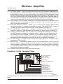
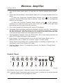
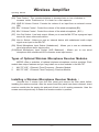
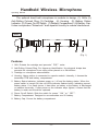
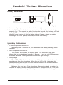
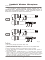
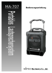
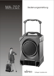
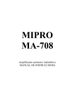
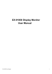
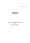
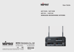
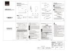
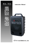
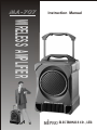
MA-707
Instruction Manual
WIRELESS AMPLIFIER
ELECTRONICS CO., LTD.
Electronics Co., Ltd.
Head office: 814, Pei-Kang Road, Chiayi, 600, Taiwan.
Taipei office: 5, Lane 118, Sung-teh Road, Taipei, 110, Taiwan.
Web-http: //www.mipro.com.tw
E-mail: [email protected]
2CE041
Wireless Amplifier
Operating Manual
Thank you for choosing a MIPRO MA-707 series Wireless Portable Public Address
System. Please take the time to read these instructions carefully so that you can
achieve the best performance from the system.
The MA-707 is a portable wireless amplifier system, housed in a heavy duty,
ergonomically designed case. It features a retractable handle and sturdy wheels for
ease of transport. It includes an innovative, dual-slot battery charger for Ni-MH
transmitter batteries to reduce the need to buy batteries for the wireless microphone
transmitters. It will operate from an internal DC rechargeable battery supply or from an
external AC mains supply. The MA-707 may be optioned with a cassette
player/recorder or single/dual VHF or UHF wireless microphone receiver modules. An
optional matching extension speaker is also available for a wider sound dispersion
pattern. The MA-707 may be operated self standing or mounted on an optional tripod
stand.
Front
1
Retractable Handle
2
Fixed Handle
3
Microphone Compartment
4
Speaker
5
Speaker Grille
6
Heat Sink
7
Tripod (Optional)
(Fig.1)
(1)
Retractable Handle: Push up from underneath the handle to expose the
retractable extension. Simply push down again for storage and lifting.
(2)
Fixed Handle: For balanced, easy hand carrying.
-1-
Wireless Amplifier
Operating Manual
(3)
Microphone Storage Compartment : A handy storage compartment for your hand
held microphone transmitters.
(4)
Speaker : A powerful, 64 watt, 8-inch full-range speaker.
(5)
Speaker Grille : To protect the speaker cone from damage.
(6)
Heat Sink : Designed specially for the built-in amplifier, please keep it adequately
ventilated.
(7)
Tripod (Optional) : There is a tripod mating socket mounted in the base of the MA707 to accommodate a 35mm tripod stand.
Back
Charging Status Indicator
8
Battery Charger
9
C. Receiver Modules
MIC BATTERY CHARGER
GROUP
CHANNEL
VOLUME
CHANNEL
VOLUME
SIGNAL AUDIO POWER
OFF
AC Power Switch
GROUP
SIGNAL AUDIO POWER
POWER
MAX
OFF
MAX
10
MODE
UTO
-A
MATIC
STOP MECHA
NIS
M
000
-
DIRECTION
A.Cassette Player
A REC/PLAY
11
DC Power Switch
12
Pitch Control
Extension Speaker Socket
DIRECTION
REC
PLAY
REW
F.F.WD
ST/EJ
PAUSE
13
B. Control Panel
MASTER
L
H
TAPE
OFF
VOLUME
Battery:12V/4AH
TONE
L
LINE IN
MIC1
MIC 2
LINE OUT
LINE IN
MIC 1
MIC 2
H
+
Steady: Full Charged
DC 24~32V
-
Flickering: Charging
+
17
Battery Cover
18
Wheels
Battery:12V/4AH
15
AC 100~240V
-
16
DC Input Socket
Charging Status Indicator
AC Input Socket
14
-
+
(Fig.2)
(8)
Charging Status Indicator (for 7.2V rechargeable transmitter batteries) : Indicates
if a 7.2V rechargeable battery is charging (RED light), or is fully charged
(GREEN light).
(9)
Battery Charger : It can hold and charge up to two 7.2V rechargeable transmitter
batteries. It has been designed to prevent incorrect insertion.
(10) AC Power Switch: Insert one end of the plug into socket (16). Insert the other end
into the AC wall socket. Finally, turn on the AC Power switch to activate charging
power.
-2-
Wireless Amplifier
Operating Manual
(11) DC Power Switch : Turns DC power on/off to the unit. The indicator glows when you
turn the power On. Please note that to avoid the over-discharging or stressing of the
built-in battery supply, it is recommended that you charge the unit immediately when
the LED indicator flashes (denoting low battery warning status). Otherwise, the unit
will turn off automatically once a pre determined low charge level is reached (and this
may interrupt your usage of the unit) The regular charging time is approx. 7~8 hours,
while a built in protection circuit will prevent the batteries from over-charging.
(12) Pitch Control: Turn this control clockwise to increase the speed of the cassette, turn it
counter-clockwise to decrease the speed of cassette. This will raise and lower the
pitch of the sound respectively.
(13) Extension Speaker Socket : Allows you to connect an optional MA-707-EXP
extension speaker for increased directional coverage. The MA-707-EXP is rated at
70 watts @ 4 ohms and connects in series to the speaker in the MA-707.
(14) DC Input Socket : Allows you to connect an external 24-32V DC power supply if
required. Please note that the polarity of the central pin in the socket is positive (+).
(15) Charging Status Indicator (For the inbuilt 12V rechargeable batteries): A flashing
red light indicates charging is in progress while a steady red light indicates that
the batteries are fully charged. However, if the indicator remains flashing after
normal charging hours (see (11)), it means the inbuilt rechargeable batteries are
damaged and both damaged inbuilt batteries must be replaced immediately.
(16) AC Input Socket : A built-in switch mode power supply allows for AC power inputs
ranging from 100V to 240V.
(17) Battery Cover : There are two battery covers, one for each battery. In the event that
you ever have to change a battery, please observe the correct polarity and always
keep the battery full-charged. Unless you experience some battery failure, changing
or uninstalling batteries should not be necessary. If in doubt, please contact your
nearest service agent or supplier.
(18) Wheels: Heavy duty and a truly user friendly feature.
Functions of the Cassette Player
MODE
UTO
-A
MATIC
STOP MECHA
NIS
M
000
-
11
Counter Reset Button
Clock Counter
DC Power Switch
12
Pitch Control
13
Extension Speaker Socket
A3
Pause Button
Stop /Eject Button
Fast Forward Button
Rewind Button
Play Mode Selector
Recording Button
Play Direction Indicator
Direction Change Switch
Auto Reverse Mode Switch
A1
A2
DIRECTION
A REC/PLAY
DIRECTION
REC
PLAY
REW
F.F.WD
ST/EJ
PAUSE
A4
A5
A6
A7
A8
A9
A10
A11
(Fig.3)
The MA-707 may be optioned to include a mechanical cassette player. Operations are as
follow:
-3-
Wireless Amplifier
Operating Manual
1. Turn ON the main power switch (11) and then turn ON the cassette player switch
(B2).
2. Select Auto Reverse Mode: Use the Mode Switch (A11) to choose playback mode you
prefer.
a. When the Continuous Playback Mode Indicator (A11)
is ON, playback
continues until the STOP button (A4) is pressed. Note: This mode is not supported
while you are recording.
b. When the Two-Side Playback Mode Indicator (A11)
is ON, playback
continues on to side B as soon as the end of side A is reached. (The tape stops
automatically once the end of side B is reached.)
3. Play: Insert cassette into cassette deck, press (A7) for playing.
4. Recording: When recording, the Direction Indicator (A9) will come ON. After pressing
the REC Button (A8) (the Play Button (A7) will be pressed automatically), recording
will start immediately. Note that recording is not possible if the erasure prevention tabs
in the cassette tape loaded in the deck have been removed.
5. Stop/Insert/Eject Cassette: Press the STOP button (A4) to stop playing cassette and
press STOP button (A4) again to eject cassette.
6. Quick Search: This feature allows you to use the Fast-Forward Button (A5) or
Rewind Button (A6) to search for a specific section of audio quickly.
7. Pause: Press Pause Button (A3) to pause playing or recording a cassette tape. To
stop pause, press Pause Button (A3) again.
8. Direction Change Switch: To change play direction, flip Direction Change Switch
(A10) upwards.
Control Panel
MASTER
L
H
B1
TAPE
OFF
VOLUME
B2
TONE
L
LINE IN
MIC1
MIC 2
LINE OUT
LINE IN
MIC 1
B4
B5
B6
B7
B8
B9
MIC 2
H
B3
B10
(Fig.4)
(B1) Master volume control : Adjust the volume of all mixed audio inputs.
(B2) Cassette Player Power Switch and Volume control : It allows you to turn the cassette
player (if installed) on/off and adjust its volume.
-4-
Wireless Amplifier
Operating Manual
(B3) Tone Control : Turn counterclockwise to increase bass or turn clockwise to
increase treble. Positioned at 12 o'clock for a flat response.
(B4) LINE IN Volume Control: Controls the volume of an input from an external source.
(B8)
(B5) Mic 1 Volume Control : Control the volume of the wired microphone.(B9)
(B6) Mic 2 Volume Control : Control the volume of the wired microphone. ( B10 )
(B7) Line Out Socket : Line level output. Allows you to use the MA-707 as a program input
source for some other audio device.
(B8) Line In Socket : Allows you use an external device with unbalanced audio output
signal as an input to the MA-707.
(B9) Wired Microphone Input Socket (Unbalanced) : Allows you to use an unbalanced,
wired microphone as an input source.
(B10)Wired Microphone Input Socket (XLR Balanced) : Allows you to use wired
microphone with a balanced XLR connector as an input source.
Types of Optional Wireless Microphone Receiver Modules.
MIPRO offers a selection of optional wireless microphone receiver modules. Each
module has unique features and you may install one or two modules in the MA-707.
1.
MA-707 VHF, 1-Channel, Fixed Frequency, Receiver Module.
2.
MA-707 UHF, 1-Channel, Fixed Frequency, Receiver Module.
Installing a Wireless Microphone Receiver Module :
Unscrew the 2 screws from the filler panel and remove the filler panel before
installing the receiver module. After the screws and filler panel have been removed, insert
receiver module into the empty slot and push it back in to it's mating connector. Uses the
screws removed previously to fasten the receiver module in position.
-5-
Wireless Amplifier
Operating Manual
Operating a Wireless Microphone Receiver Module
MA-707-X
MA-707-V/VD/U
VOLUME
SIGNAL AUDIO POWER
OFF
C4 C3 C2
MAX
C1
(C1) Receiver Power Switch and Volume Control : Allows you to turn power on/off to
the receiver module and adjust its volume.
(C2) Power Indicator : Indicates receiver power status.
(C3) Audio Indicator : Indicates the volume level of the wireless microphone.
(C4) Signal Presence Indicator : The light turns ON when a signal from the wireless
microphone is detected.
Helpful Hints
1.
2.
3.
4.
5.
6.
7.
8.
9.
Please make sure the inbuilt rechargeable batteries are fully charged before and
after use. Battery itself has such a special characteristic of self-discharging gradually
over a long period of time. Therefore, if the system will not be used for a long period
of time, please make sure the batteries are fully charged before storing them properly.
Company Warranty DOES NOT apply to over-discharged batteries, hence, please
ensure the batteries are recharged every 3 months.
If you are operating the system from the internal, DC battery supply, you can expect
up to 5 hours of continuous use from a full charge on well conditioned batteries. If
you choose to operate the system from an external AC power supply, then the
internal battery supply will charge at the same time a very useful feature.
If the LED indicator on the power switch flashes after first turning the unit ON or it
starts to do so during use on the internal DC supply, you should switch to the AC
power supply by using the AC power cord.
Before turning power ON to the unit, please set all volume controls to their minimum
level. This prevents any loud 'thumps' at power on. Adjust the volume controls
afterward.
You can use the record feature of the cassette deck while the system is in use.
Please refer to the operating instructions for the wireless microphone for more details
on its use.
NEVER place any microphone close in front of the speaker otherwise damaging
feedback (both to the operators ears and the system) could occur.
The MA-707 features a retractable handle and wheels for easy transport. However,
DO NOT pull the unit for long distances or over uneven or rough surfaces. And, DO
NOT pull it up or down stairs. Vibration caused by long distance travel or travelling
over uneven surfaces may result in function failure not covered by warranty.
Charging time for MA-707 is 8 hours. To ensure long batter life, please remove AC
power plug when the system is fully charged.
-6-
Wireless Amplifier
Operating Manual
10.
11.
12.
The MA-707-EXP extension speaker is rated at 60 watts @ 4 ohms. Please take
care not to short out the speaker cables otherwise unwarranted damage could be
done to the system amplifier.
Battery is an expendable item. Under normal operation, MIPRO offers one year
limited warranty.
When experiencing short operating time after batteries are fully charged, it is often a
sign with aging batteries. Both rechargeable batteries must be replaced at your
earliest convenience.
Specifications
Specification
Item
1. Max. Power Output
64 Watts (RMS) in to a 4
Load
2. T.H.D.
<0.1%
3. Frequency Response
60Hz~20KHz 3dB
4. Input Sources
Optional Wireless Microphone Receiver, Cassette Player,
CD Player, Wired Microphone, External Audio input.
5. Speaker
Built-in 8 inch Full-range Speaker.
6. Power Supply
Built-in 85V~265V Switching Power Supply.
7. Cycle TimeI
Use continuously for 5 hours after charging for 8 hours.
8. Receiver Module
Optional UHF and VHF receiver modules are available Up
to 2 receiver modules may be fitted to an MA-707.
Please consult with your supplier for frequencies
suitable in your area.
9. Wireless Microphone
If so configured, suitable for use with optional hand held,
belt pack or head worn microphones/transmitters.
10. Wired Microphone
Use a Low Impedance, Dynamic Microphone
11. Audio Inputs
Accepts an Optional Cassette Recorder or an external
Compact Disc Player ( a 6.3
plug is needed)
12. Dimension
435 300 230mm
13. Weight
13.5Kg
14. Exterior Color
Black
Please Note:
Not all models are available in all markets and specific
model configurations may vary from market to market. Please
consult with your local supplier for detail of the various
models/configurations available in your market.
The suitability of wireless microphone frequencies may
vary from location to location. Please consult with your
supplier for advice about frequencies suitable in your area. No
responsibility is taken by Mipro for interference caused to/by
any wireless microphone frequency transmission/reception
under any circumstance.
Caution: Danger of explosion if battery is incorrectly replaced.
Replace only with the same or equivalent type.
-7-
Handheld Wireless Microphone
Operating Manual
The optional hand held microphone is modular in design. (1) Grille (2)
Anti-Rolling Colored Ring (3) Cartridge (4) Housing (5) Battery Status
Indicator (6) Power On-Off Switch (7) Battery Compartment (8) Battery Cap.
It also incorporates "NoiseLock" dual-squelch circuitry to reduce interference.
ON
OFF
VHF
1
2
3
5
4
6
7
8
(Fig.1)
Features
1. Grill: Protects the cartridge and prevents " POP " noise.
2. Anti-Rolling Colored Ring: For frequency identification. Its polygonal shape also
prevents the microphone from rolling when placed on a flat surface.
3. Cartridge or microphone element/insert.
4. Housing: Upper portion is connected to capsule module. Internally, it houses the
transmitter PCB and battery compartment.
5. Battery Status Indicator: Indicates power on / off and the battery status. When the
power switch is turned ON, the red LEDs indicator flashes briefly, indicating normal
battery status. If no flash occurs, it has either no battery or the battery is discharged
or installed incorrectly. If after power on the indicator stays lighted, it warns that the
battery is weak and should be replaced.
6. Power On-off Switch: Slide the switch for power " ON " or " OFF ".
7. Battery Compartment: Designed to accommodate one 9V battery.
8. Battery Cap: Covers the battery compartment.
-8-
Handheld Wireless Microphone
Operating Manual
Battery Installation
OFF
ON
+
(Fig.2)
1. Unscrew battery cap in a counter-clockwise direction (8).
2. Insert a 9V battery into the battery compartment according to the correct polarity as
shown in Fig.2. The moment the battery touches the terminals, the indicator will flash
briefly (8). This means the polarity is correct. However, if no flash occurs, this
indicates wrong insertion or that the battery is dead. Please re-insert the battery
according to its correct polarity or exchange it for a fresh battery.
Operating Instructions
1. As the microphone is switched on:
When the power is switched on, the indicator will flash briefly indicating normal
operation.
2. After microphone is switched on:
The SIGNAL LED indicator on receiver glows. The more LEDs that glow
indicate that the received signal strength is stronger. If only the red LED illuminates
it indicates abnormal receiving status and insufficient signal strength.
3. During Usage:
The AUDIO LED indicator on the receiver will illuminate according to the audio
signal strength from the microphone. When the red LED is ON, it indicates that
maximum sound pressure level has been reached but does not represent distortion.
4. When the microphone is not in use:
Make sure that you turn off the microphone after use to extend the battery life.
Remove the battery from the battery compartment if microphone is not to be used
again for some time. If a rechargeable battery was used, take it out and recharge it.
-9-
Handheld Wireless Microphone
Operating Manual
This microphone utilizes advanced modular assembly and PLL
synthesized design. Preprogrammed with frequencies allows the user to
freely select non-interference channels. It also incorporates "Pilotone &
NoiseLock dual-squelch" to eliminate noise interference.
PLL
3
13 1
5
1
7
11
5
CHANNEL
UNUSED CHA
9
UHF
2
2
UNUSED C
3
9
1
3
4
8
10
9
1
8
10
4
5
6
7
5
6
7
GROUP
CHANNEL
(Fig.1)
Features
1. Grille: Protects cartridge and prevents "POP" noise.
2. Rolling Proof Color Ring: For frequency differentiation and its polygonal shape
prevents microphone from rolling.
3. Battery Compartment: Designed to accommodate one piece 9V battery.
4. Housing: Upper portion to be connected to capsule module and battery. Internally, it
holds transmitter PCB.
5. Battery Status Indicator: Indicates the power on / off and battery status. When power
switch is turned ON, the red LEDs indicator flashes briefly, indicating normal battery
status. If no flash occurs, it has either no battery or the battery is drained or installed
incorrectly. After power on and the indicator stays lighted. It warns the battery is
weak and a new battery replacement is thus necessary.
- 10 -
Handheld Wireless Microphone
Operating Manual
6.
7.
8.
9.
Power On-off Switch: Slide the switch for power " ON" or "OFF".
Group Changer Cover: Open cover to switch to Group Frequency Selection.
Channel Selection Cover: Open cover to switch to desired frequencies.
Unused Indicator: When LED glows it indicates an untransmitt signal or an empty
group or channel was selected. When microphone is power ON, LED will glow for
approx. 2 seconds and then fades.
10.Selector Cover: Protect channel changers and accidental switching.
11.Battery Cap: Covers the battery compartment.
Battery Installation
(Fig.2)
1. Unscrew battery cap in counter-clockwise direction (Fig. 2).
2. Insert a 9V battery into the battery compartment according to the correct polarity as
shown in Fig.2. The moment the battery touches the terminals of compartment, the
indicator (5) will flash briefly. This means the polarity is correct. However, if no flash
occurs, this indicates wrong insertion. Please re-insert the battery according to its
correct polarity.
Operating Instructions
1. As the microphone is switched on:
When the power is switched on, the indicator will flash briefly indicating normal
operation.
2. After microphone is switched on:
The SIGNAL LED indicator on receiver glows. The more LEDs that glow
indicate that the received signal strength is stronger. If only the red LED illuminates
it indicates abnormal receiving status and insufficient signal strength.
3. During Usage:
The AUDIO LED indicator on the receiver will illuminate according to the audio
signal strength from the microphone. When the red LED is ON, it indicates that
maximum sound pressure level has been reached but does not represent distortion.
4. When the microphone is not in use:
Make sure that you turn off the microphone after use to extend the battery life.
Remove the battery from the battery compartment if microphone is not to be used
again for some time. If a rechargeable battery was used, take it out and recharge it.
- 11 -
Belt Pack Transmitter
Operating Manual
Features
(PHONE JCAK)
MIC
2
GAIN
7
MT
6
GT
5
LOCK VOLUME
3
4
MIC
1
(4 PIN JACK)
7
8
8
11
11
OFF
9
OFF
ON
9
BATT.LOW
10
1.
ON
BATT.LOW
10
Phone Jack Input Connector: Connects to a phone jack 3.5mm connector (if so
configured). Allow for lavalier and headset microphones.
2. 4-Pin Jack Input Connector: Connect to a MIPRO 4-pin connector (if so configured).
Allows 5 for different input connections. (See 5 ways of connection on AF Input
Connections later in this booklet).
3. Volume Control Bypass Switch (if fitted): When the switch is in the 'up' position, the
volume control is bypassed and the level is set to maximum. When switch is at
'down' position the volume control is fully operational.
4. Volume Control: Adjusts the audio input level from the microphone/auxiliary source,
to the transmitter.
5. GT/MT Switch (if fitted): Switch to the GT position for electric guitar usage ONLY.
The Gain Control is bypassed in "GT" mode. Switch to the "MT" for condenser
microphone, wired microphone or Line-in. The Gain Control operates in the "MT"
mode for adjusting input sensitivity.
6. Gain Control: Adjusts the input gain. Please take care not to inadvertently turn the
level down for a loss of signal, or up to induce feedback.
7. Transmitter Housing: Houses the PCB and battery.
8. Battery Status Indicator: Indicates the power on / off and battery status.
(a) When power switch is turned on the LED indicator flashes briefly, indicating
normal battery status.
(b) When the RED light illuminates at either power on or during use, it indicates
that the battery level is low, therefore a new battery is required.
9. Power Switch: Switch to ON position for operation. Switch to OFF position when not
in use.
10. Battery Compartment and Cover: Accommodates one 9V battery.
11. Detachable Belt Clip: Pull slightly towards you and push down according to the
arrow direction to release the belt clip.
- 12 -
Belt Pack Transmitter
Operating Manual
Operating Instructions
1.
Push down to open the battery compartment cover (10) as shown in Fig.1.
2.
Insert a 9V battery into the battery compartment according to the correct polarity as
shown in Fig.2 Then push up to close the battery compartment as shown in Fig.3.
OFF
ON
BATT.LOW
+
(Fig.1)
(Fig.2)
(Fig.3)
3.
The LED indicator flashes briefly at power on indicating normal battery status. If no
flash occurs it has either no battery, the battery is drained or is installed incorrectly.
Change accordingly.
4.
Phone Jack (if fitted): When the switch is in the 'up' position, the volume control is
bypassed and the level is set to maximum. When switch is at 'down' position the
volume control is fully operational (3). Adjusts the audio input level from the
microphone/auxiliary source, to the transmitter (4).
5.
4-Pin Jack (if fitted): Volume can be adjusted via the Gain control. The Gain control
has no effect when switched to GT (Guitar) usage.
6.
4-Pin Jack: Align and insert the plug to jack accordingly and tighten it in the
clockwise direction as shown in figure 4.
Capsule Connectort
Headset
Please aim of the fillister
and insert the connector
Lavalier
MIC
(Fig.4)
7.
Phone Jack: Insert the plug accordingly and tighten it in the clockwise direction.
- 13 -
Belt Pack Transmitter
Operating Manual
AF 4-Pin Input Connection Methods
(1) 2-Wire Electret condenser microphone Capsule
PIN
1
SHIELD
AUDIO
2
1 4
2 3
3
4PIN
PLUG
4
(2) 3-Wire Electret condenser microphone Capsule
PIN
1
SHIELD
2
AUDIO
1 4
2 3
3
BIAS
4PIN
PLUG
4
(3) Dynamic Microphone
2
1
SHIELD
3
PIN
1
2
AUDIO
1 4
2 3
3
4PIN
PLUG
4
(4) Electric Guitar
SHIELD
PIN
1
2
AUDIO
3
4
(5) Line-in (Impedance 8K
1 4
2 3
4PIN
PLUG
ATT. 10dB)
SHIELD
AUDIO
PIN
1
2
1 4
2 3
3
4
- 14 -
4PIN
PLUG
Belt Pack Transmitter
Operating Manual
Features
(XLR JCAK)
VHF
1
2
3
4
PLL
12
5
6
7
8
9
10
11
UHF
(Fig.1)
1.
AF Input Jack: Connects to either lavaliere or headset microphone. (See 5 ways of
connection on AF Input Connections)
2. Power Switch: Switch to ON position for operation. Switch to OFF position when
not in use.
3. Battery Status Indicator: Indicates the power on / off and battery status.
(a) When power switch is turned on: The LED indicator flashes briefly, indicating
normal battery status.
(b) When RED light illuminates at either power on or during usage: The battery
level is low, therefore, a new battery replacement is thus necessary.
4. Transmitting Antenna: 1/ 4
transmitting antenna.
5. Transmitter Housing: Packages the PCB and battery.
6. Group Changer: For Group Selection. (UHF)
7. Channel Changer: Preprogrammed with 30 frequencies. Allow 1-30 channels
switchable option. (UHF / PLL)
8. Unused Status Indicator: When LED lights on, it denotes un-transmitted signals.
9. Gain Control: Adjusts the desirous input gain.
10. GT/MT Level Select Switch: Switch GT position for electric guitar usage ONLY.
Gain Control is irrelevant for "GT". Switch to "MT" for condenser microphone,
wired microphone. Gain Control works in "MT" for input sensitivity adjusting.
11. Battery Compartment and Cover: Accommodates one piece 9V battery.
12. Detachable Belt Clip: Pull slightly towards you and push down according to the
arrow direction to release the belt clip.
- 15 -
Belt Pack Transmitter
Operating Manual
Operating Instructions
1.
To adjust frequency group (6), frequency channel (7), volume (9), GT/MT Switch (10),
and read the unused indicator (8), simply push down both snap locks on the sides
of battery cover and flip it backwards to expose the adjustment panel.
2.
Before power on, ascertain if same channel (7) was set up for both receiver and
microphone. If not adjust to same channel accordingly.
3.
The LED indicator flashes briefly when power on indicating normal battery status. If
no flash occurs it has either no battery, the battery is drained or installed incorrectly.
Change accordingly.
4.
Adjust Gain Control to desired volume. (Gain Control is irrelevant when switch to
GT position).
5.
Plug the microphone connector into the input jack (1) and tighten the connector
screw by clockwise direction as shown in (Fig. 2).
Capsule Connectort
Headset
Lavalier
Please aim of
the fillister
and insert the
connector
(Fig.2)
- 16 -
Belt Pack Transmitter
Operating Manual
AF 4-Pin Input Connection Methods
(1) 2-Wire Electret condenser microphone Capsule
PIN
1
SHIELD
AUDIO
2
3
4
4PIN
PLUG
(2) 3-Wire Electret condenser microphone Capsule
SHIELD
PIN
1
2
AUDIO
3
BIAS
4
4PIN
PLUG
(3) Dynamic Microphone
2
1
SHIELD
3
PIN
1
2
AUDIO
3
4PIN
PLUG
4
(4) Electric Guitar
SHIELD
PIN
1
2
AUDIO
3
4
(5) Line-in (Impedance 8K
SHIELD
AUDIO
4PIN
PLUG
ATT. 10dB)
PIN
1
2
3
4
4PIN
PLUG
- 17 -
Belt Pack Transmitter
Operating Manual
Battery Installation
1.
Pushing down both snap locks on the sides of battery cover to open battery cover.
Take out the batteries. Fig.(3).
2.
Insert a 9V battery into the battery compartment according to the correct polarity as
shown in Fig. (4). Then push up to close the battery compartment as shown in Fig.
(4).
(Fig.3)
(Fig.4)
- 18 -