1
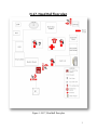
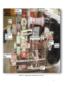
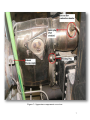
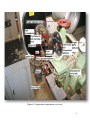
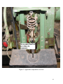
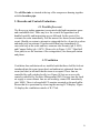
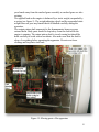
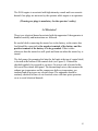
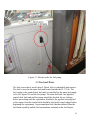
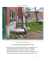
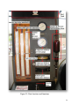
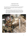
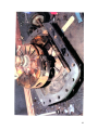
STANDARD OPERATING PROCEDURE AND
SAFETY GUIDE FOR ROVER GAS TURBINE
APPARATUS
(Located in Rm. H-17 Head Hall)
Prepared
May 16, 2010
1
Table of Contents
1. Scope ........................................................................................................................................4
1.1 Objective ............................................................................................................................4
1.2 Regulations ........................................................................................................................4
2.Apparatus Overview and objective ...........................................................................................4
2.1 Apparatus overview ...........................................................................................................4
3. Hazards and control evaluation..............................................................................................21
3.1 Possible fire event ............................................................................................................21
3.2 Ventilation........................................................................................................................21
3.3 Kinetic, thermal & accoustic............................................................................................22
3.4 Electrical ..........................................................................................................................25
3.5 Fuel and Water .................................................................................................................26
3.6 General, physical & equipment concerns ........................................................................28
3.7 Access ..............................................................................................................................30
3.8 Training ............................................................................................................................30
3.9 Personal equipment ..........................................................................................................30
4. Operation................................................................................................................................30
4.1 Qualified personnel ..........................................................................................................30
4.2 Experiment preparation....................................................................................................30
4.3 Lab instructions ................................................................................................................32
4.4 Operating procedure.........................................................................................................34
5. Inspections .............................................................................................................................36
5.1 Operational & Periodic inspections .................................................................................37
6. Typical test .............................................................................................................................37
Appendix A: Lab Script .............................................................................................................38
Appendix B: Rover 60 hp gas turbine engine ............................................................................39
Appendix C: Operator’s Handbook ...........................................................................................40
Appendix D: Spare Parts Catalogue ..........................................................................................41
Appendix E: Heenan-Froude Dynamometer .............................................................................42
2
H-17, Head Hall floor plan
Figure 1: H-17, Head hall floor plan
3
1. Scope
1.1 Objective
This standard operating procedure is intended to provide operating
instructions and safety information for the Department of Mechanical
Engineering’s Rover Gas Turbine experiment apparatus located in H-17,
Head Hall. This document is intended as a guideline and supplement to
proper training that must be provided by qualified personnel before the
apparatus is operated. The aim of this document is to ensure that safe work
practices have been developed for the Rover Gas Turbine experimental
work. This SOP is primarily concerned with the operating procedure of the
apparatus, hazards involved in the experiment and safety precautions that
must be taken to avoid injuries.
1.2 Regulations
This document has been developed in accordance with the Environmental
Health and Safety Office of the University of New Brunswick.
2. Apparatus Overview and Objective
2.1 Apparatus overview
The experimental apparatus admits ambient air through two sideways air
intakes into the compressor housing. There is an airmeter thermometer
mounted on the intake of airmeter to measure the temperature of air being
pulled in to the IS/60 engine. The Airmeter has a 4.5 inches diameter venturi
in it for computation of the air mass flow. The compressor in the
compressor housing is a single stage centrifugal pump and consists of a 17
guide vanes impeller machined from an aluminum alloy forging. The vanes
of the impeller have curved leading edges to assist air entry into the eye of
the impeller. The air is then pumped by the blades of the impeller to the
reverse flow combustion chamber of the IS/60 engine. The combustion
chamber consists of an igniter plug which is connected to a battery via an
igniter box and a keyed ignition. When the starter key is turned clockwise
(3rd position) on the keyed ignition, the engine starts up with the compressor
pumping air into the combustion chamber and out of the apparatus through
exhaust. The engine is running on battery power until it reaches a constant
RPM of about 4000 RPM, then the fuel operating lever is opened and the
igniter plug on combustion chamber produces sparks which in turn start the
combustion of air/fuel mixture in the combustion chamber.
4
There is a fuel burner, fuel operating lever and fuel accumulator bulb on
the apparatus. The fuel burner contains a fuel atomizer, which sprays jets of
fuel into the combustion chamber for the combustion process. The fuel
operating lever connects/disconnects the fuel supply to the combustion
chamber by controlling a fuel shut-off valve in the fuel burner. The fuel
accumulator stores fuel under pressure and ensures good fuel atomization for
engine starting purposes. The fuel accumulator is always unscrewed before
starting the experiment to purge trapped fuel that has already collected, into
a beaker/bottle. It is then screwed tight again to proceed with the
experiment. Please see figure 2, 3 and 4 for details and description of the
components.
5
Figure 2: Apparatus components overview
6
Figure 3: Apparatus components overview
7
Figure 4: Apparatus components overview
8
The hot gases from the combustion chamber are guided through volute (air
passage assembly) to the turbine rotor, where the gases expand against the
single stage axial turbine and work is done. The turbine is a nimonic
forging in which the blades and disc are machined integrally. The blades are
of free vortex design. The turbine rotor is attached to the compressor shaft
by a single large diameter nimonic bolt. The main air casing of the
apparatus consists of a fuel drain assembly and oil drain assembly (oil
drain assembly drains the used oil into the oil sump). Bolted to the front face
of the compressor housing is the aluminum alloy auxiliaries mounting
plate to which are attached both the oil pump and the fuel control unit. The
fuel control unit consists of a centrifugal type governor to avoid over
speeding of the engine by controlling the amount of fuel to the combustion
chamber. The unit also has a fuel filter in it. There is a temperature control
located in the exhaust and connected to the fuel control unit, which prevents
the engine from operating at excessive temperatures by operating a valve to
return fuel to the suction side of the pump at a predetermined exhaust
temperature and reducing the amount of fuel to the combustion chamber.
The oil pump and fuel control units are both driven from the turbine shaft by
an internal train of reduction gearing. The IS/60 engine has a 3000 RPM
reduction gearing and the turbine output pinion in the centerline of
compressor and turbine assembly protrudes outward from the meshed gears.
The output pinion rotates counter clock wise when viewed from the rear of
the IS/60 engine.
The output pinion is connected to the Heenan and Froude type
dynamometer assembly. The engine and dynamometer are mounted on a
fabricated mild steel bed plate of substantial channel section. The amount
of load on the IS/60 engine is controlled by a load adjusting wheel which is
turned to increase or decrease the load on the IS/60 engine. If the load is
increased, the RPM of the engine decreases and to keep the RPM constant a
throttle lever on the control desk is used to increase/decrease the RPM of
the engine, and RPM indicator displays the RPM of the engine. The weight
adjusting wheel is turned to balance the dynamometer assembly (see figure
2, 4 & 5 to understand the dynamometer assembly and how to balance the
dynamometer). Please refer to Appendix ‘A’ (Heenan - Froude
Dynamometer) to completely understand the working of Heenan & Froude
dynamometer. Also see figure 6 and 7 for details and description of the
apparatus components.
9
Figure 5: Apparatus components overview
10
Figure 6: Apparatus components overview
11
Figure 7: Apparatus components overview
The apparatus consists of a control desk, which has a fuel tank located at its top.
The fuel is pumped in to the fuel tank by a fuel pump located at the bottom of
control desk. The fuel flow from the main fuel storage tank (located outside the
12
H-17 Lab) to the fuel pump is controlled by main fuel supply valve. There are
number of pressure and temperature displays of the apparatus on the control desk
during operation of the apparatus. The impeller tip pressure gauge and
compressor delivery pressure gauge measure and display the impeller tip
pressure of the compressor and entering air pressure of the compressor. The
exhaust gases are exhausted through an exhaust extension and there is an
exhaust temperature indicator on the control desk to display the exhaust gases
temperature. The control desk has a measuring flask mounted on it to measure
the amount of fuel consumed by the engine. There is also a compressor delivery
temperature indicator, exhaust temperature indicator, airmeter depression
manometer and turbine outlet static pressure manometer mounted on it to
display the temperatures and pressures as desired by the user. There are total 5
thermocouples connected to the apparatus, one for the compressor delivery
temperature and the rest for the exhaust gases temperature. The thermocouples are
connected to the control desk to display the temperatures via a junction panel.
Please see figures 8, 9 and 10 for details and description of the apparatus
components.
Please refer to Appendix ‘B’ (Rover 60 hp gas turbine engine) to see the details on
the technical data and specifications of the engine, lubrication system, fuel
system, electrical equipment, dynamometer and instrumentation.
Please refer to appendix ‘C’ Operator’s handbook to see the specifications of the
components of the apparatus and also refer to appendix ‘D’ (spare parts catalogue)
to see the complete details and description of all the components and parts of the
apparatus.
The purpose of the Lab is to operate the Rover gas turbine at a constant speed at
an increasing load as provided by the dynamometer. The fuel consumption is
monitored as well as the various pressures and temperatures.
13
Figure 8: Apparatus components overview
14
Figure 9: Apparatus components overview
15
Figure 10: Apparatus components overview
16
The compressor housing consists of an oil return pipe in front and an oil
sump at the bottom. The oil sump collects the oil already used by the IS/60
engine/Rover Gas Turbine and has the capacity of five pints. The used oil in
the oil sump can be drained by unscrewing the oil sump drain plug. There
is an oil temperature bulb screwed with the oil sump to measure the
temperature of oil in the sump and the temperature is indicated on oil
temperature gauge. Please see figure 11 and 12 for details and description
of some of the other important components of the apparatus
17
Figure 11: Apparatus components overview
18
Figure 12: Apparatus components overview
19
The pressure of oil pumped into the oil filter is measured and indicated on
the oil pressure gauge. There is an oil level dipstick to check the oil level
in the IS/60 engine. Please see figure 13 below for description
Figure 13: Apparatus components overview
20
The oil filler tube is situated at the top of the compressor housing together
with the breather pipe.
3. Hazards and Controls Evaluation:3.1 Possible fire event
The Rover gas turbine apparatus is associated with high temperature gases
and combustible fuel. There may be a fire event if the apparatus is not
handled carefully and instructions are not followed. In the event of fire,
evacuate the room immediately. Pull the nearest fire alarm (located outside
room). Should you return to attempt to extinguish the fire, do not do so alone
and make only one attempt. If unsuccessful then leave immediately. If
successful stay at the scene and have someone alert Security (ph. # 4830)
and Campus Safety (ph. # 5075). Please refer to Figure 1 (H-17 Head hall
floor plan) to see the locations of fire extinguishers, fire alarm pull station
and phone.
3.2 Ventilation
Ventilation fans and ductwork are installed such that there shall be fresh air
introduced into the room (green duct) and ambient air exhausted from the
room (teal duct) at all times that the room is occupied. These fans are
controlled by wall switches locally (see Figure 14) but are on over-ride
controls controlled by Facilities Management (FM). If at any time the fresh
air supply or room exhaust fans are not working, contact FM immediately
(ph # 4889). There is a household CO monitor mounted on the north pillar.
Ensure that it is operational by observing the moving LCD display. Figure
14 displays the ventilation controls of H-17 lab.
21
Figure 14: Ventilation controls of room H-17
3.3 Kinetic, Thermal and Acoustic
The moving parts associated with the apparatus are the load adjusting wheel,
static weight, weight adjusting wheel and the output pinion shaft on which
the compressor and turbine are mounted. Load is applied on the IS/60 engine
by turning the load adjusting wheel. It does not pose any serious kinetic
threat if handled carefully. There is a meshed gear assembly underneath the
load adjusting wheel to transmit the motion of wheel to the dynamometer.
While turning the load adjusting wheel, be careful and keep the fingers of
22
your hands away from the meshed gears assembly as meshed gears are also
rotating.
The applied load on the engine is balanced by a static weight, suspended by
a spring (see figure 5). The weight adjusting wheel and the suspended static
weight does not pose any kinetic threat if handled carefully during the
operation.
The output pinion shaft connected to the dynamometer however poses
serious threat. Body parts should be kept away from the shaft while the
engine is running. The output pinion shaft is in safe casing but should be
dealt carefully to avoid serious accidents. Also make sure that the shaft is
clear of everything before operating the apparatus. Do not wear loose
clothing and keep hairs tied back.
Figure 15: Moving parts of the apparatus
23
The apparatus is associated with very high temperatures. The combustion
chamber and the engine exhaust are associated with very high temperature
gases approximately 600°C-700°C. Do not touch the main air casing,
combustion chamber and engine exhaust while the engine is operating
as they are an extreme thermal hazard. There is no risk associated with
the effluent gases since the exhaust ductwork is extended to the roof top and
exhausted to the atmosphere.
Figure 16: Exhaust extension
24
The IS/60 engine is associated with high intensity sounds and is an acoustic
hazard if ear plugs are not worn by the operator while engine is in operation.
(Wearing ear plugs is mandatory for the operator’s safety)
3.4 Electrical
There is no electrical hazard associated with the apparatus if the apparatus is
handled carefully and instructions are followed.
Be careful while connecting the starter box to the battery, as the starter box
lead should be connected to the negative terminal of the battery and the
positive terminal of the battery is to be grounded. If this is done
otherwise then the starter box will spark and burn-out when the starter key is
turned.
The fuel pump (for pumping fuel into the fuel tank at the top of control desk)
is located at the bottom of the control desk (see Figure 8). It should be
checked regularly for exposed or cut wires. Its power cord is located at the
left rear of the control desk/panel. The thermocouple wires, that measure the
exhaust gas temperature and the compressor delivery temperature, are
insulated and do not pose any electric threat. The apparatus should be
routinely checked for bare or cut electrical wires each time prior operation
so as to avoid electrical hazards.
25
Figure 17: Electric outlet for fuel pump
3.5 Fuel and Water
The fuel source that is used is diesel. Diesel fuel is combustible and reactive.
The fuel is stored in the main fuel tank located outside the H-17 Lab. The
fuel supply to the control desk fuel tank is controlled by the main fuel supply
valve (see figure 20) and the fuel pump. The main fuel tank, fuel pipeline,
control desk fuel tank and fuel pump should be checked for any leakage
before proceeding with the experiment. Similarly, the pipeline carrying fuel
to the engine from the control desk should be checked for any leakage before
beginning the experiment. Any accumulated fuel, that has drained from the
fuel drain assembly and the fuel accumulator mounted on the fuel burner,
26
should be collected by proper means to prevent fuel spillage. Diesel is
combustible and exposure of spilled diesel to a spark can cause an ignition.
Water flow is supplied to the apparatus for the operation of the
dynamometer and for the cooling of oil. A water/oil heat exchanger cools the
oil. Water from the heat exchanger as well as the dynamometer is sent to
water exhaust drain. Always make sure that water is flowing to drain. Water
leakage or spillage is not very dangerous by itself, but should be avoided as
water can cause electrical equipment failure. The pressure of the water
entering the dynamometer is displayed on the water pressure indicator (see
figure 4).
27
Figure 18: Fuel and Water
Figure 19: Main fuel tank location
3.6 General, physical and equipment concerns
The apparatus is associated with high pressures and very high temperatures.
The gas turbine incorporates a temperature control as an overriding
safeguard to high temperatures. This device consists of a temperature
sensing tube that projects into the exhaust stream. It is connected by
capillary tubing to the fuel control unit. Over-loading of the engine results in
increased engine operating temperatures. Should the temperature rise above
28
the predetermined level, the temperature control automatically reduces the
fuel supply to the fuel burner unit, until the temperature falls below the
engine design limit. Excessive overheating of the engine results in a fuel
supply termination and an automatic engine shut-down.
Figure 20: Main fuel supply valve location
The fuel control unit also has a mechanical governor to maintain the engine
speed at 46,000 RPM. The mechanical governor is connected to a valve in
the fuel control unit in such a way that a decrease or increase in the engine
speed (caused by varying loads applied to the engine) results in a greater or
lesser amount of fuel being supplied to the fuel burner. In do so it restores
the speed to the correct parameter. If the engine RPM indicator is not
accurate and shows incorrect RPM, then the RPM indicator should be
29
properly adjusted first rather than the mechanical governor. The majority of
maintenance operations will be conducted using the RPM indicator, so this
device should be checked regularly for proper operation.
3.7 Access
All personal in the H-17 laboratory should be preauthorized by the faculty in
charge or under the supervision of authorized personal (lab technician or
teacher assistant). No person other than the faculty supervisor in charge or
specifically authorized personal are permitted to make alterations to, or to
run experiments with the Rover gas turbine apparatus.
3.8 Training
All individuals using the apparatus shall be required to receive training in
the proper operation and maintenance of the apparatus and its controls.
Training will include such topics as the complete operation and control of
the apparatus. Training programs shall be administered only by qualified
personnel at UNB.
3.9 Personal Protective Equipment
Following personal protective equipment is required while using the
apparatus:
• Ear plugs
4. Operation
4.1 Qualified Personal
These notes in the operation section will provide a guideline to the
individual that has been trained by a qualified personal to operate the Rover
Gas Turbine apparatus. Only after the individual has been trained and feels
confident with the apparatus operation and shutdown procedures should he
or she attempt to operate the apparatus using these notes. Do not proceed if
you are not properly trained or are unsure in any manner of the safe
operation of the apparatus and its associated safety concerns.
30
4.2 Experiment Preparation/Startup
Following steps should be carried out to prepare for the experiment:
• Ensure that the fuel drain assembly (See figure 7) is not faulty and
that the apparatus is not inclined upwards at the exhaust end, so that
complete fuel drainage is not impaired. If fuel drainage is affected,
then there is a possibility of engine over speeding at start-up due to a
large amount of residual fuel accumulation in the combustion
chamber or main air casing. Fuel may be present after a failed engine
start-up. The fuel might also accumulate due to a slight leak at the fuel
burner. This accumulated fuel produces an over rich air/fuel mixture
during the engine start-up period. Dangerous conditions can result if
the amount of accumulated fuel is excessive. The engine might
accelerate to an unduly high speed and temperature at start-up. Before
starting the apparatus, unscrew the fuel drain valve and replace it after
all the fuel in the main air casing has drained. A defective fuel drain
assembly should be rectified and replaced immediately.
• Ensure that the engine is free of load (check that the dynamometer
hand wheel is closed). The engine should not be started with a load
already applied to it.
• Ensure that the main fuel supply valve (see figure 20) is open and that
the fuel pump is switched on and is actively pumping fuel to the fuel
tank, located at the top of the apparatus. The apparatus fuel tank
should be full before commencing the experiment.
• Turn on the fuel control knob on the control desk so that the fuel
measuring flask is full of fuel. Then shut-off the fuel supply by
turning the fuel control knob to off.
• Unscrew the fuel accumulator a few turns to release already
accumulated fuel and allow air to enter the accumulator bulb. Then
screw the fuel accumulator down until it is finger tight.
31
• Ensure that the air intakes are clean and clear.
• Turn on the water supply by opening the main water supply valve.
The water pressure should be 15 psi minimum for oil cooling and can
be checked by the water pressure indicator on the apparatus. Open the
water flow to the apparatus 15 minutes prior to starting the experiment
so that the water is at a constant room temperature (21°C). Also
ensure that the water used by the apparatus for the cooling of oil and
for the dynamometer is properly draining.
• Set the throttle lever on the control desk to the 1/2 way position.
4.3 Lab Instructions
4.3.1 Instructor Responsibilities
The Standard Operating Procedure for the apparatus shall be reviewed and
well comprehended. This document provides all the necessary information
regarding the apparatus startup procedure, operation, hazards involved &
safety precautions to be taken while using this apparatus. The lab instructor
shall remain in the room while the experiment is in progress. When the
entire student group has assembled, and before any explanation has begun,
the instructor shall relay all safety precautions and hazards as outlined in
section 3. Inform all students that they must contact the instructor, should
any problems or concerns arise during the experiment. Make the group
aware of the fire extinguisher locations, fire alarm pull stations, phone and
exits. Any student from the group missing the required personal protective
equipment shall not be allowed by the instructor to enter the laboratory H-17
and to proceed with the experiment.
4.3.2 Data/Instruments Locations and Functions
Please refer to Figure 21 to see the location of data display units and their
functions:
•
•
Compressor delivery pressure gauge - (displays the pressure of gases
delivered to the compressor).
Compressor delivery temperature gauge - (displays the temperature of
gases delivered to the compressor).
32
•
•
•
•
•
Exhaust gases temperature indicator - (displays the temperature of
exhaust gases leaving the exhaust).
Impeller tip pressure gauge – (displays the compressor impeller tip
pressure).
Turbine inlet pressure manometer – (displays the pressure of gases
entering the turbine).
Turbine outlet pressure manometer – (display the pressure of gases
leaving the turbine).
Airmeter depression manometer – (displays the pressure drop across
the airmeter venturi).
33
Figure 21: Data locations and functions
34
4.4 Operating Procedure
4.4.1 Experiment procedure
After preparing for the experiment and following all the steps mentioned in
section 4.2 to prepare for this experiment, follow the following steps to
complete the experiment:
•
With the fuel operating lever (mounted on the fuel burner) in the
closed position, turn the starter motor switch key clockwise through
60° (i.e. to Position 3) and hold against spring pressure when starter
motor is operating. Once the engine starts then the key will return
back to position 2.
Figure 22: Fuel burner assembly
35
•
When the engine speed reaches a constant ≈ 400 RPM on the
tachometer (RPM indicator), open the fuel burner (atomizer) by
turning the fuel operating lever and the engine will fire up. The
combustion of air in the combustion chamber will be indicated by the
“ROARING” of the engine.
•
At approximately 2500 RPM, after the cut-out switch has
disconnected the starter motor, turn the starter key to “OFF” and
remove the key.
•
When the engine reaches a steady speed, check the following:
a. Engine speed is not appreciably over 2500 RPM.
b. Oil pressure is at least 7 Psi and temperature is less than 110°C.
If conditions of either ‘a’ & ‘b’ are not satisfied then immediately shut
down the apparatus and abort the experiment. Notify the lab
technician about the problem so that the cause can be investigated.
•
Gradually set the control desk engine throttle lever from the 1/2 way
position to obtain the desired speed (RPM).
•
Load the dynamometer as required to obtain different readings for the
experiment. When the engine is loaded its RPM decreases, so
balance the load with the hanging static weight to keep RPM constant.
Use the control desk throttle lever to increase the RPM of the engine.
(an increased RPM increases fuel consumption of the engine)
4.4.2 Normal Shutdown
Follow this procedure to shut down the gas turbine apparatus:
•
Remove the dynamometer load and ensure there is no load on the
engine.
•
Move the control desk throttle lever to shut off position.
•
Shut off the fuel burner (atomizer) by turning the fuel operating lever.
36
•
Turn off the fuel pump.
•
Turn off the main fuel supply valve (see figure 20) and the control
desk fuel control knob.
•
Turn off the water supply to the apparatus by turning the main water
supply valve OFF.
•
Before leaving the lab, ensure that there are no objects left on the
apparatus. Clean the apparatus with a piece of cloth.
4.4.3 Emergency Shutdown
Follow the following procedure in given order to shut down the gas turbine
apparatus in case of emergency:
1.
2.
3.
4.
5.
6.
7.
8.
Shut off the fuel burner (atomizer) by turning the fuel operating lever.
Move the control desk throttle lever to shut off position.
Turn off the fuel pump.
Turn off the main fuel supply valve (see figure 20) and the control
desk fuel control knob.
Turn off the water supply to the apparatus by turning the main water
supply valve OFF.
Remove the dynamometer load and ensure there is no load on the
engine.
Before leaving the lab, ensure that there are no objects left on the
apparatus. Clean the apparatus with a piece of cloth.
Notify instructor of any problems or reasons that the experiment was
terminated.
5.0 Inspection
Inspections at regular intervals shall be performed on the apparatus to ensure
that the apparatus is kept in a safe and well maintained condition. The
inspection includes the observation of any cracks in main fuel tank, control
desk fuel tank, fuel & water pipe line, leaks in combustion chamber and
engine exhaust and a routine check for bare & cut electrical wires in the
apparatus.
37
5.1 Periodic & Operational Inspections
Visual inspections are the responsibility of the person who is conducting
experiments on a regular basis with the Rover Gas Turbine apparatus and
should be carried out each time before operating the apparatus. A complete
periodic inspection of the apparatus shall be performed by the person who is
conducting experiments on a regular basis with this apparatus. That same
person will alert the faculty supervisor of any deficiencies in the apparatus.
The deficiencies such as those listed below shall be examined during both
the periodic & operational inspection. The faculty supervisor will determine
if the deficiencies will affect the safe operation of the apparatus.
a. Function, temperature and pressure displays and warning labels.
b. Worn, cut or bare electrical wires.
c. Cracked fuel tank, fuel & water pipeline leaks and worn or corroded
pipes.
d. Pierced pipes and leaks in the main air casing, exhaust and
combustion chamber.
6.0 Typical Tests
The actual test procedure will be outlined in the lab script as issued by the
professor (faculty supervisor). A typical test includes the calculation of
Brake horse power, Thermal efficiency, Fuel consumption, Brake specific
fuel consumption, Air/fuel ratio, percent excess air and compressor pressure
ratio. Please refer to Appendix ‘A’ to see the detailed lab script, sample
calculations and experiment results.
38
Appendix ‘A’
39
Appendix ‘B’
40
Appendix ‘C’
41
Appendix ‘D’
42
Appendix ‘E’
43
44