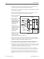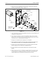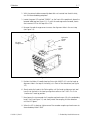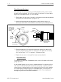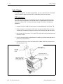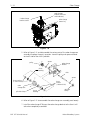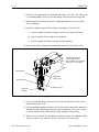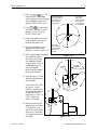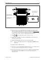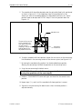
1
Technical Manual for
the EMT 10T
embroidery peripheral
•
•
•
•
•
Part Number 110291-01, Revision D
Single Head, Ten Needles
Tubular Goods Hooping
Automatic Color Change
Under Thread Control
1575 West 124th Avenue
Denver, Colorado 80234
United States of America
Internet Address: [email protected]
Copyright © Melco Embroidery Systems, 1997, 1998
ALL RIGHTS RESERVED No part of this publication may be reproduced, stored in a retrieval system, or
transmitted in any form or by any means (electronic, mechanical, photocopying, recording, or
otherwise) without prior written approval of Melco Embroidery Systems. Melco reserves the right to
revise this publication and to make changes in it at any time without obligation of Melco to notify any
person or organization of such revisions or changes.
All precautions have been taken to avoid errors or misrepresentations of facts, equipment, or products.
However, Melco Embroidery Systems does not assume any liability to any party for loss or damage
caused by errors or omissions.
Printed in the United States of America
First Printing:
Revision B:
Revision C:
Revision D:
January, 1997
June, 1997
March, 1998
June, 1998
Table of Contents
1. Introduction
Scope Of Manual . . . . . . . . . . . . . . . . . . . . . . . . . . . . . . . . . . . . . . . . . . . . . .
Standard Conventions Used In Manual . . . . . . . . . . . . . . . . . . . . . . . . . . . . . .
Glossary Of Terms . . . . . . . . . . . . . . . . . . . . . . . . . . . . . . . . . . . . . . . . . . . . . .
Maintenance Philosophy . . . . . . . . . . . . . . . . . . . . . . . . . . . . . . . . . . . . . . . . .
Good Maintenance Practice . . . . . . . . . . . . . . . . . . . . . . . . . . . . . . . . . . .
Static Electricity . . . . . . . . . . . . . . . . . . . . . . . . . . . . . . . . . . . . . . . . . . . .
Grounding Strap Use . . . . . . . . . . . . . . . . . . . . . . . . . . . . . . . . . . . . .
Warranty Considerations . . . . . . . . . . . . . . . . . . . . . . . . . . . . . . . . . . . . .
Electrical Grounding . . . . . . . . . . . . . . . . . . . . . . . . . . . . . . . . . . . . . . . . . . . .
Functional Arrangement . . . . . . . . . . . . . . . . . . . . . . . . . . . . . . . . . . . . . . . . .
Configuring the EMT 10T . . . . . . . . . . . . . . . . . . . . . . . . . . . . . . . . . . . . . . . .
Configuration Procedure . . . . . . . . . . . . . . . . . . . . . . . . . . . . . . . . . . . . .
Troubleshooting LEDs and Test Points . . . . . . . . . . . . . . . . . . . . . . . . . . . . . . .
Various Technical Specifications . . . . . . . . . . . . . . . . . . . . . . . . . . . . . . . . . . .
1-1
1-1
1-2
1-2
1-3
1-3
1-3
1-3
1-4
1-4
1-5
1-5
1-6
1-8
2. Service Maintenance (except head and trimmer)
General . . . . . . . . . . . . . . . . . . . . . . . . . . . . . . . . . . . . . . . . . . . . . . . . . . . . . . 2 - 1
Drive Belt Tensions . . . . . . . . . . . . . . . . . . . . . . . . . . . . . . . . . . . . . . . . . . 2 - 1
Keyboard Section . . . . . . . . . . . . . . . . . . . . . . . . . . . . . . . . . . . . . . . . . . . . . . 2 - 2
Keyboard/Display Replacement. . . . . . . . . . . . . . . . . . . . . . . . . . . . . . . . . 2 - 2
Display Screen Intensity . . . . . . . . . . . . . . . . . . . . . . . . . . . . . . . . . . . . . . 2 - 3
Disk Drive . . . . . . . . . . . . . . . . . . . . . . . . . . . . . . . . . . . . . . . . . . . . . . . . . . . . 2 - 4
Lamp Assembly . . . . . . . . . . . . . . . . . . . . . . . . . . . . . . . . . . . . . . . . . . . . . . . . 2 - 4
Bobbin Winder . . . . . . . . . . . . . . . . . . . . . . . . . . . . . . . . . . . . . . . . . . . . . . . . 2 - 5
E-Stop Switch Replacement. . . . . . . . . . . . . . . . . . . . . . . . . . . . . . . . . . . . . . . 2 - 6
Power Distribution Section . . . . . . . . . . . . . . . . . . . . . . . . . . . . . . . . . . . . . . . 2 - 8
Voltage Adjustments . . . . . . . . . . . . . . . . . . . . . . . . . . . . . . . . . . . . . . . . 2 - 8
Remove Table Top . . . . . . . . . . . . . . . . . . . . . . . . . . . . . . . . . . . . . . . . . . 2 - 8
Module Replacement . . . . . . . . . . . . . . . . . . . . . . . . . . . . . . . . . . . . . . . . 2 - 8
Electronics Section . . . . . . . . . . . . . . . . . . . . . . . . . . . . . . . . . . . . . . . . . . . . 2 - 11
Remove Table Top . . . . . . . . . . . . . . . . . . . . . . . . . . . . . . . . . . . . . . . . . 2 - 11
Remove Card Cage Cover . . . . . . . . . . . . . . . . . . . . . . . . . . . . . . . . . . . 2 - 11
Card Cage Components. . . . . . . . . . . . . . . . . . . . . . . . . . . . . . . . . . . . . 2 - 12
CPU PCB. . . . . . . . . . . . . . . . . . . . . . . . . . . . . . . . . . . . . . . . . . . . . . . . . 2 - 12
Ethernet Network PCB . . . . . . . . . . . . . . . . . . . . . . . . . . . . . . . . . . . . . . 2 - 13
Interface PCB . . . . . . . . . . . . . . . . . . . . . . . . . . . . . . . . . . . . . . . . . . . . . 2 - 14
Low Voltage Driver PCB . . . . . . . . . . . . . . . . . . . . . . . . . . . . . . . . . . . . . 2 - 14
XYZ Motor Driver Amplifiers. . . . . . . . . . . . . . . . . . . . . . . . . . . . . . . . . . 2 - 15
Backplane PCB . . . . . . . . . . . . . . . . . . . . . . . . . . . . . . . . . . . . . . . . . . . . 2 - 15
EMT 10 Technical Manual
i
110291-01, Revision D
Table of Contents
X Beam Assembly . . . . . . . . . . . . . . . . . . . . . . . . . . . . . . . . . . . . . . . . . . . . .
X Motor . . . . . . . . . . . . . . . . . . . . . . . . . . . . . . . . . . . . . . . . . . . . . . . . .
Motor Replacement . . . . . . . . . . . . . . . . . . . . . . . . . . . . . . . . . . . . .
X Drive Belt. . . . . . . . . . . . . . . . . . . . . . . . . . . . . . . . . . . . . . . . . . . . . . .
Replacement . . . . . . . . . . . . . . . . . . . . . . . . . . . . . . . . . . . . . . . . . .
Belt Tension . . . . . . . . . . . . . . . . . . . . . . . . . . . . . . . . . . . . . . . . . . .
Lint Wiper. . . . . . . . . . . . . . . . . . . . . . . . . . . . . . . . . . . . . . . . . . . . . . . .
Y Motor . . . . . . . . . . . . . . . . . . . . . . . . . . . . . . . . . . . . . . . . . . . . . . . . .
Replacement . . . . . . . . . . . . . . . . . . . . . . . . . . . . . . . . . . . . . . . . . .
Y Motor Belt. . . . . . . . . . . . . . . . . . . . . . . . . . . . . . . . . . . . . . . . . . . . . .
Belt Tension Adjustment. . . . . . . . . . . . . . . . . . . . . . . . . . . . . . . . . .
Y Drive Belt. . . . . . . . . . . . . . . . . . . . . . . . . . . . . . . . . . . . . . . . . . . . . . .
Replacement . . . . . . . . . . . . . . . . . . . . . . . . . . . . . . . . . . . . . . . . . .
Belt Tension Adjustment. . . . . . . . . . . . . . . . . . . . . . . . . . . . . . . . . .
2 - 17
2 - 17
2 - 17
2 - 19
2 - 19
2 - 20
2 - 21
2 - 21
2 - 21
2 - 23
2 - 23
2 - 25
2 - 25
2 - 28
3. Embroidery Head Maintenance
General . . . . . . . . . . . . . . . . . . . . . . . . . . . . . . . . . . . . . . . . . . . . . . . . . . . . . . 3 - 1
Arm and Bed Assembly . . . . . . . . . . . . . . . . . . . . . . . . . . . . . . . . . . . . . . . . . . 3 - 1
Z Motor. . . . . . . . . . . . . . . . . . . . . . . . . . . . . . . . . . . . . . . . . . . . . . . . . . . . . . 3 - 1
Replacement . . . . . . . . . . . . . . . . . . . . . . . . . . . . . . . . . . . . . . . . . . . . . . 3 - 1
Belt Tension . . . . . . . . . . . . . . . . . . . . . . . . . . . . . . . . . . . . . . . . . . . . . . . 3 - 3
Z Shaft Encoder. . . . . . . . . . . . . . . . . . . . . . . . . . . . . . . . . . . . . . . . . . . . . . . . 3 - 3
Introduction . . . . . . . . . . . . . . . . . . . . . . . . . . . . . . . . . . . . . . . . . . . . . . . 3 - 3
Inspection. . . . . . . . . . . . . . . . . . . . . . . . . . . . . . . . . . . . . . . . . . . . . . . . . 3 - 4
Installation . . . . . . . . . . . . . . . . . . . . . . . . . . . . . . . . . . . . . . . . . . . . . . . . 3 - 5
Calibration . . . . . . . . . . . . . . . . . . . . . . . . . . . . . . . . . . . . . . . . . . . . . . . . 3 - 6
Thread Tensioner Assembly. . . . . . . . . . . . . . . . . . . . . . . . . . . . . . . . . . . . . . . 3 - 9
Assembly Removal . . . . . . . . . . . . . . . . . . . . . . . . . . . . . . . . . . . . . . . . . . 3 - 9
Thread Guide Tubes . . . . . . . . . . . . . . . . . . . . . . . . . . . . . . . . . . . . . . . . 3 - 10
Individual Thread Tensioner Replacement. . . . . . . . . . . . . . . . . . . . . . . . 3 - 10
Check Spring Replacement. . . . . . . . . . . . . . . . . . . . . . . . . . . . . . . . . . . 3 - 11
Check Spring Adjustment. . . . . . . . . . . . . . . . . . . . . . . . . . . . . . . . . . . . 3 - 12
Adjustment Hints . . . . . . . . . . . . . . . . . . . . . . . . . . . . . . . . . . . . . . . 3 - 12
Replacing A Thread Break Contact Post . . . . . . . . . . . . . . . . . . . . . . . . . 3 - 13
Jump Stitch Solenoid. . . . . . . . . . . . . . . . . . . . . . . . . . . . . . . . . . . . . . . . . . . 3 - 14
Replacement . . . . . . . . . . . . . . . . . . . . . . . . . . . . . . . . . . . . . . . . . . . . . 3 - 14
Adjustment . . . . . . . . . . . . . . . . . . . . . . . . . . . . . . . . . . . . . . . . . . . . . . 3 - 16
Plunger Positioning. . . . . . . . . . . . . . . . . . . . . . . . . . . . . . . . . . . . . . 3 - 16
Bracket Positioning . . . . . . . . . . . . . . . . . . . . . . . . . . . . . . . . . . . . . . 3 - 17
Color Change . . . . . . . . . . . . . . . . . . . . . . . . . . . . . . . . . . . . . . . . . . . . . . . . 3 - 18
PCB Replacement . . . . . . . . . . . . . . . . . . . . . . . . . . . . . . . . . . . . . . . . . . 3 - 18
Color Change Motor Replacement . . . . . . . . . . . . . . . . . . . . . . . . . . . . . 3 - 19
Color Change Motor Belt Tension . . . . . . . . . . . . . . . . . . . . . . . . . . . . . 3 - 21
Color Change Cam Assembly Replacement . . . . . . . . . . . . . . . . . . . . . . 3 - 21
110291-01, Revision D
ii
EMT 10 Technical Manual
Table of Contents
Needle Case . . . . . . . . . . . . . . . . . . . . . . . . . . . . . . . . . . . . . . . . . . . . . . . . .
Replacing Needle Bar / Presser Foot / Associated Parts . . . . . . . . . . . . . .
Needle Case Removal . . . . . . . . . . . . . . . . . . . . . . . . . . . . . . . . . . . . . .
Replacing Needle Case Cross Roller Bearing . . . . . . . . . . . . . . . . . . . . . .
Cross Roller Bearing Centering . . . . . . . . . . . . . . . . . . . . . . . . . . . . . . . .
Retainer Plate Bearing Adjustment . . . . . . . . . . . . . . . . . . . . . . . . . . . . .
Replacing Reciprocator / Needle Bar Guide Shaft . . . . . . . . . . . . . . . . . .
Installing Needle Case . . . . . . . . . . . . . . . . . . . . . . . . . . . . . . . . . . . . . .
Lower Rail Retainer Adjustment . . . . . . . . . . . . . . . . . . . . . . . . . . . . . . .
Rotary Hook . . . . . . . . . . . . . . . . . . . . . . . . . . . . . . . . . . . . . . . . . . . . . . . . .
Hook Replacement . . . . . . . . . . . . . . . . . . . . . . . . . . . . . . . . . . . . . . . . .
Adjust The UTC Assembly. . . . . . . . . . . . . . . . . . . . . . . . . . . . . . . . .
Needle Depth . . . . . . . . . . . . . . . . . . . . . . . . . . . . . . . . . . . . . . . . . .
Hook Timing Adjustments Only . . . . . . . . . . . . . . . . . . . . . . . . . . . . . . .
UTC Adjustments . . . . . . . . . . . . . . . . . . . . . . . . . . . . . . . . . . . . . . .
3 - 24
3 - 24
3 - 26
3 - 28
3 - 28
3 - 30
3 - 31
3 - 33
3 - 35
3 - 36
3 - 36
3 - 38
3 - 39
3 - 42
3 - 44
4. Trimmer Maintenance
General . . . . . . . . . . . . . . . . . . . . . . . . . . . . . . . . . . . . . . . . . . . . . . . . . . . . . . 4 - 1
Sequence of Trim Events . . . . . . . . . . . . . . . . . . . . . . . . . . . . . . . . . . . . . . . . . 4 - 1
Trimmer Replacement Procedures . . . . . . . . . . . . . . . . . . . . . . . . . . . . . . . . . . 4 - 2
Grabber Drive Assembly . . . . . . . . . . . . . . . . . . . . . . . . . . . . . . . . . . . . . . 4 - 2
Grabber Blade . . . . . . . . . . . . . . . . . . . . . . . . . . . . . . . . . . . . . . . . . . . . . 4 - 3
Trimmer Drive Assembly . . . . . . . . . . . . . . . . . . . . . . . . . . . . . . . . . . . . . . 4 - 4
Trimmer Cam . . . . . . . . . . . . . . . . . . . . . . . . . . . . . . . . . . . . . . . . . . . 4 - 4
Trimmer Solenoid . . . . . . . . . . . . . . . . . . . . . . . . . . . . . . . . . . . . . . . . 4 - 4
Picker Solenoid Assembly . . . . . . . . . . . . . . . . . . . . . . . . . . . . . . . . . . . . . 4 - 6
Home Position Optical Switch. . . . . . . . . . . . . . . . . . . . . . . . . . . . . . . . . . 4 - 6
Picker Assembly . . . . . . . . . . . . . . . . . . . . . . . . . . . . . . . . . . . . . . . . . . . . 4 - 6
Movable Knife . . . . . . . . . . . . . . . . . . . . . . . . . . . . . . . . . . . . . . . . . . . . . 4 - 7
Adjustable Fixed Knife/Under Thread Presser . . . . . . . . . . . . . . . . . . . . . . 4 - 8
Movable Knife Drive Arm . . . . . . . . . . . . . . . . . . . . . . . . . . . . . . . . . . . . . 4 - 9
Trimmer Adjustment Procedures . . . . . . . . . . . . . . . . . . . . . . . . . . . . . . . . . . 4 - 10
General . . . . . . . . . . . . . . . . . . . . . . . . . . . . . . . . . . . . . . . . . . . . . . . . . 4 - 10
Z Timeout Errors . . . . . . . . . . . . . . . . . . . . . . . . . . . . . . . . . . . . . . . . . . . 4 - 10
Damaged Trimmer Cam or Trimmer Solenoid. . . . . . . . . . . . . . . . . . 4 - 11
Checking "Head Up" Position . . . . . . . . . . . . . . . . . . . . . . . . . . . . . 4 - 12
Trimmers Not Trimming Properly . . . . . . . . . . . . . . . . . . . . . . . . . . . . . . 4 - 13
Physical Condition Of Trimmer Parts. . . . . . . . . . . . . . . . . . . . . . . . . 4 - 13
Adjustable Fixed Knife . . . . . . . . . . . . . . . . . . . . . . . . . . . . . . . . . . . . . . 4 - 13
Under Thread Presser . . . . . . . . . . . . . . . . . . . . . . . . . . . . . . . . . . . . . . . 4 - 14
Adjustable Fixed Knife Adjustment . . . . . . . . . . . . . . . . . . . . . . . . . . . . . 4 - 16
Ink Wipeoff Test . . . . . . . . . . . . . . . . . . . . . . . . . . . . . . . . . . . . . . . . 4 - 16
Knife Adjustment . . . . . . . . . . . . . . . . . . . . . . . . . . . . . . . . . . . . . . . 4 - 17
Cut Threads . . . . . . . . . . . . . . . . . . . . . . . . . . . . . . . . . . . . . . . . . . . 4 - 18
Movable Knife Home Position . . . . . . . . . . . . . . . . . . . . . . . . . . . . . . . . 4 - 18
Home Position Sensor. . . . . . . . . . . . . . . . . . . . . . . . . . . . . . . . . . . . . . . 4 - 20
Checking Select Position. . . . . . . . . . . . . . . . . . . . . . . . . . . . . . . . . . . . . 4 - 21
Select Position Adjustment . . . . . . . . . . . . . . . . . . . . . . . . . . . . . . . . . . . 4 - 22
EMT 10 Technical Manual
iii
110291-01, Revision D
Table of Contents
Picker Finger Position . . . . . . . . . . . . . . . . . . . . . . . . . . . . . . . . . . . . . . .
Picker Home Position . . . . . . . . . . . . . . . . . . . . . . . . . . . . . . . . . . . . . . .
Picker Height/Depth Position . . . . . . . . . . . . . . . . . . . . . . . . . . . . . . . . .
Grabber Adjustment. . . . . . . . . . . . . . . . . . . . . . . . . . . . . . . . . . . . . . . .
Under Thread Control (UTC) Replacement . . . . . . . . . . . . . . . . . . . . . . . . . .
UTC Adjustments . . . . . . . . . . . . . . . . . . . . . . . . . . . . . . . . . . . . . . . . . . . . .
Rotary Hook Retaining Finger Positioning . . . . . . . . . . . . . . . . . . . . . . . .
Sew Test. . . . . . . . . . . . . . . . . . . . . . . . . . . . . . . . . . . . . . . . . . . . . . . . .
Preliminary Checks . . . . . . . . . . . . . . . . . . . . . . . . . . . . . . . . . . . . . .
Perform The Test . . . . . . . . . . . . . . . . . . . . . . . . . . . . . . . . . . . . . . .
4 - 24
4 - 25
4 - 25
4 - 26
4 - 28
4 - 29
4 - 29
4 - 32
4 - 32
4 - 32
5. Accessory Adjustments
Wide Angle Cap Frame . . . . . . . . . . . . . . . . . . . . . . . . . . . . . . . . . . . . . . . . . .
Cap Supports . . . . . . . . . . . . . . . . . . . . . . . . . . . . . . . . . . . . . . . . . . . . . .
Cap Support Pads. . . . . . . . . . . . . . . . . . . . . . . . . . . . . . . . . . . . . . . . . . .
Driver Bar Cable . . . . . . . . . . . . . . . . . . . . . . . . . . . . . . . . . . . . . . . . . . . .
Spindles On The Clamps. . . . . . . . . . . . . . . . . . . . . . . . . . . . . . . . . . . . . .
Clip Posts . . . . . . . . . . . . . . . . . . . . . . . . . . . . . . . . . . . . . . . . . . . . . . . . .
Cap Frame . . . . . . . . . . . . . . . . . . . . . . . . . . . . . . . . . . . . . . . . . . . . . . . .
5-1
5-1
5-2
5-2
5-3
5-3
5-4
INDEX
110291-01, Revision D
iv
EMT 10 Technical Manual
1-1
1. Introduction
Scope Of Manual
The EMT 10T Embroidery Peripheral Technical Manual is a guide for performing
repairs and adjustments which go beyond routine operator maintenance.
Although these procedures are best understood and performed by professional
service technicians in conjunction with specific factory technical training, much of
the information in this manual may be useful reference for others who might
possess appropriate technical aptitude and skills.
If any information in this manual is not fully understood, however, you are advised
to contact your local Melco equipment service organization for assistance. You will
find they are professional service technicians trained on Melco equipment, who
have acquired technical expertise through experience and other general technical
training. Additionally, Melco equipment technicians routinely receive up to date
servicing information which continually enhances their product knowledge.
This technical manual is presented in four Sections: 1) an overview of general
information useful in understanding the manual and various service requirements,
2) service maintenance of all the machine areas except the embroidery head, 3)
embroidery head maintenance (excluding trimmers), and 4) service maintenance on
the embroidery head trimmer area. Sections 2, 3, and 4 address mechanical
disassembly and replacement of the major components of the embroidery
peripheral and any related machine adjustments.
Standard Conventions Used In Manual
Throughout this manual abbreviations and specific terms may be used. The
following explains some of this terminology:
When speaking of a "printed circuit board," the item may quite often be referred
to as a "PCB."
The terms "X Beam", "Y Beam", "Beam", "Carriage", "Carriage Assembly" and
"Pantograph" may all refer to the same general area.
Certain procedures in the manual require actions such as pressing a certain key, or
typing some letters at the computer keyboard. The following is a list of some of the
more commonly used conventions found in this manual.
• To indicate a key on the computer keyboard, the key in question is simply
referred to, for example: Press the Enter key to initiate the application.
• A key on the peripheral keyboard is represented by a pictorial of that key.
• Typing with the computer keyboard is referred to in BOLD letters, for
example: Type: run and press Enter to start.
110291-01, Rev D
1. Introduction
1-2
Maintenance Philosophy
• To indicate that two or more keys must be pressed to obtain a desired
result, each key is indicated with commas between them. An example is:
Press Shift,8 to type an asterisk (*).
Occasionally in the manual, special attention by the user is required. In this
situation, "attention getters" are used to indicate the need for the user to be aware
of a situation that is above and beyond the normal or routine. Three standard
attention getters are explained below:
WARNING!
This term is used to call attention to the user that the procedure
following must be performed with care and accuracy to avoid possible
damage to property or personal injury to the operator or other persons in
the area. This term is also used to announce important regulatory
information.
CAUTION!
This term is used when the procedure following it may cause damage
to the equipment or other property if not properly performed by the user.
NOTE:
This term is used when additional information is required beyond
the normal steps for communicating the information. It may be used to
clarify certain portions of text or to call attention to other items previously
mentioned or mentioned later in the procedure.
Glossary Of Terms
Several words or terms are used in this manual that are unique or specialized in use
with the embroidery industry or Melco embroidery equipment. A glossary of these
terms is located in the operation manual.
Maintenance Philosophy
The maintenance philosophy used in this manual, and practiced at Melco, is to
isolate potential problems within the system to a "practical" replacement assembly.
Therefore, components are typically not repaired, but rather, a circuit board or
mechanical "assembly" may be replaced. In the process of isolating problems in the
machine, the person performing the trouble shooting must also practice good
trouble shooting techniques. Good trouble shooting techniques include, but are not
limited to, guarding against static electricity causing further damage to machine
components; and only replacing one part at a time to enable identification of the
defective part after the machine is repaired.
EMT 10T Technical Manual
Melco Embroidery Systems
Warranty Considerations
1-3
Good Maintenance Practice
The procedures in this manual are guidelines for performing repair maintenance
and must be used by personnel practicing good maintenance and repair technique.
Good maintenance technique includes, but is not limited to, adhering to all
precautions and safety considerations when working on the unit, and using the
correct tools for the job being performed.
WARNING! Personal injury may result if proper precautions are
not observed. Remove rings, watches, and any other metallic
objects from hands and wrists before servicing the machine.
Remove metallic articles from shirt pockets to prevent them
from falling into the machine. Do not place hands under the
needle or needle bar. Do not allow loose clothing to come in
contact with moving parts of the machine. Under certain
conditions of machine failure the moving parts of the machine
may not be controllable by normal means. At these times the
machine may operate without notice.
Static Electricity
As with all computerized equipment, the EMT 10T Embroidery Peripheral is sensitive
to static electricity. Any time work is performed inside covered areas of the
embroidery peripheral, the person performing the work MUST be using a static
grounding strap.
WARNING! Failure to use a grounding strap, or failure to
practice other good maintenance/repair techniques may cause
damage to the machine and possible harm to personnel.
Grounding Strap Use
The grounding strap must be connected in the proper manner to insure the static
charge on the persons body is neutralized to the chassis ground level of the
embroidery peripheral when working in the electronic areas under the covers.
DO NOT attempt to use any grounding strap that is not specifically designed for
static use. A "straight-wire" grounding device (one without built-in resistance) will
place the operator in danger of exposure to dangerous voltages. It is recommended
that the static strap be checked during daily use for proper resistance protection.
Warranty Considerations
Many areas of maintenance in this manual require factory trained personnel to
assure proper service. Any service that is improperly performed may cause the
warranty to be voided.
110291-01, Rev D
1. Introduction
1-4
Functional Arrangement
Electrical Grounding
WARNING! It is very important that the power cord be plugged
into a properly wired electrical outlet. Failure to have a
properly wired outlet may result in damage to the equipment
and injury to personnel. It is recommended that a licensed
electrician be consulted to assure that the electrical outlet is
properly wired and grounded.
CAUTION! If a properly wired electrical outlet is not used for the source supply
voltage to the System, electrical failures may result.
Functional Arrangement
The EMT 10T is functionally arranged into several sections including the electronics,
a power supply section, the keyboard and disk drive the Embroidery Head, and the
Carriage section. Figure 1-1 shows the general locations of these and other
functional parts of the embroidery peripheral.
tensioner
and
needle
case
thread tree
flexible
lamp
Keyboard
and Disk
Drive
power supply
section
(under rear
table top or
optional
bobbin winder
assembly)
electronics
section
(under rear
table top)
carriage
ON/OFF
switch
assembly
indicator LED lights
and test points (cover
offset from shipping
configuration)
serial #
tag
Figure 1 - 1
EMT 10T Technical Manual
Melco Embroidery Systems
Configuration Procedure
1-5
Configuring the EMT 10T
Occasionally during the operation of the EMT 10T, certain situations may arise
when the peripheral software simply "locks up."
You may often recover from this type of situation by performing what is called
"Configuring" (or Re-configuring) the embroidery peripheral. (When this type of
situation happens with a computer, you are usually asked to perform a "soft
reboot" [Ctrl], [Alt], [Del].)
You must also configure the peripheral any time you install a new CPU (Central
Processor Unit) printed circuit board.
Configuration is initially set at the factory. However, if for any reason the
configuration is not set properly, or if you have replaced the CPU board, you should
know how to set the configuration.
NOTICE: Re-configuring your EMT 10T will clear the power fail rescue function for
the current situation.
There are two items that must be set in each EMT 10T Embroidery Peripheral before
it is used in the Melco system for the first time.
First you must set the Peripheral Program. The CPU PCB used on the EMT 10T
Embroidery Peripheral may also be used in other embroidery peripherals produced
at Melco. Therefore, you must tell the CPU board what peripheral it is being used in.
If the CPU PCB is ever replaced, you must reconfigure the peripheral before using it
again.
CAUTION! If the EMT 10T is not configured with the correct Peripheral Program, it
will not run properly, and may become damaged.
The second configuration item is the Network Address. The address must be
different for each peripheral attached to an EDS II or EDS III computer or network.
There may be up to 64 (16 if using EDS II software) total embroidery peripherals
attached to any one computer, and each must have its own unique identification.
The EMT 10T uses an Ethernet network card which allows the address to contain
the numbers 0 through 9, all 26 English letters, three symbols (-, /, and *), or any
combination of these characters. The maximum number of characters that can be
used in the network address is sixteen.
Configuration Procedure
Refer to the operation manual for the procedure to configure or re-configure the
EMT 10T Embroidery Peripheral.
110291-01, Rev D
1. Introduction
1-6
Troubleshooting LEDs and Test Points
Troubleshooting LEDs and Test Points
At the front of the EMT 10T is a metal cover plate over a variety of indicator LED
lights and a series of test points for checking certain voltages with a multimeter.
This area is provided for observing various machine conditions, especially while
troubleshooting problems that may occasionally occur. To access this area, remove
the screws holding the cover, flip the cover over so the lettering on the cover is
visible (as shown in Figure 1-2), and reinstall the cover in the same holes but above
the LED opening. The lettering on flip-side of the cover is a brief title for each of the
LED and test point locations. You may also refer to Figure 1-3 for this information.
lettering on
metal cover
indicator LED
lights and
test points
Figure 1 - 2
EMT 10T Technical Manual
Melco Embroidery Systems
Configuration Procedure
1-7
GREEN (all should be ON)
1) I/O FPGA (I/O IC on CPU configured OK at startup)
2) Control FPGA (Control IC on CPU configured OK at startup)
3) +5V (Power OK from CPU)
4) +6V (Isolated) OK
* TEST POINT Voltage Tolerances
5) +36V OK (see note **)
6) +24V OK
+6 VDC ISO (+5.6 to +6.1 VDC)
7) -12V OK
+36 VDC [without load] (+30 to +37 VDC)
8) +12V OK
+36 VDC [with 20-100% load] (+34.2 to +37.8 VDC)
9) +5V (+12V based) OK
+24 VDC (+22.8 to +25.2 VDC)
10) +5V (+24V based) OK
-12 VDC (-10.8 to -13.2 VDC)
+12 VDC (+11.4 to +12.6 VDC)
RED (all should be OFF)
+5 VDC (+4.9 to +5.1 VDC)
1) Estop Engaged
2) Light Fuse Blown
3) Bobbin Fuse Blown
4) Grabber Motor Current Limit Error
ISO RET (Isolated GND)
5) Color Change Motor Current Limit Error
+6 VDC ISO *
6) Z Motor Current Limit Error
+36 VDC *
7) Y Motor Current Limit Error
+24 VDC *
8) X Motor Current Limit Error
9) Y Home not functioning
10) X Home not functioning
GREEN
RED
GREEN
YELLOW
1 2 3 4 5 6 7 8 910
1 2 3 4 5 6 7 8 910
1 2 3 4 5 6 7 8 910
1 2 3 4 5 6 7 8 910
Note ** +36 VDC
When the peripheral is first
turned on and before the
program is downloaded,
the +36.0 VDC LED may be
blinking. This is normal. But
after the machine initializes,
and the motors become
energized, if the blinking
does not stop the power
supply may be marginal.
TEST POINTS *
TEST POINTS *
-12 VDC *
+12 VDC *
+5 VDC *
GND
Note *** Hall - Sensors in the
motor which indicate defective
(dead spot) sections in the
motor. Only OFF at dead spot
positions in the motor rotation.
GREEN
YELLOW
(2) through (5) ON, others as indicated)
(conditions as indicated)
(ON only at Head Up) Z Index (1
Watch Dog (2
(6) & (7)
(see note ***) Z Hall (3
ON until motors
(see note ***) Y Hall (4
initiated, then OFF
(see note ***) X Hall (5
Color Chg & Grabber Motor Brakes (6
XYZ Motor Brakes (7
(8) will flicker
during trim OFF when Grabber is Home (8
Y Home (9
(9) & (10) ON - one side of axis center,
X Home (10
OFF - other side of axis center
10) Cut Home #1 (OFF when Home)
9) (disregard, 4-Head Only)
8) (disregard, 4-Head Only)
7) (disregard, 4-Head Only)
6) UTC #1 (should flicker while stitching)
5) (disregard, 4-Head Only)
4) (disregard, 4-Head Only)
3) (disregard, 4-Head Only)
2) Standard Cap Frame (ON when Installed)
1) Wide Angle Cap Frame (ON when Installed)
EMT 10T
Figure 1 - 3
110291-01, Rev D
1. Introduction
1-8
Various Technical Specifications
Various Technical Specifications
The following is a list of various tension and force specification for the EMT 10T (All
specifications to be within plus or minus 10% unless otherwise indicated):
X Drive Belt Tension. . . 25 lbs. measured on top portion with carriage to left side
Y Drive Belt Tensions . . . . . 40 lbs. measured on top portion with beam full back
Y Motor Belt Tension. . . . . . . . . . . . . . . . . . . . . 40 lbs. pushing down on motor
Z Motor Belt Tension. . . . . . . . 7 pounds (+/- 1) measured on one portion of belt
Color Change Motor Belt Tension . . . . . . 6 lbs. measured on top portion of belt
X Carriage Friction. . . . . . . . . . . . . . . . . . . . . . . . . . . . . . . . . . . . 5 +/- 2 pounds
Y Beam Friction . . . . . . . . . . . . . . . . . . . . . . . . . . . . . . . . . . . . . 12 +/- 4 pounds
NOTE:
A special force gauge has been designed for adjusting the belt tensions using
unique methods that are representative of these tension specifications.
The following lists the X and Y home positions attained when the "Set Home"
function is initiated on the EMT 10T embroidery peripheral.
X Home . . . . . . . . . . centered within +/- 0.015 inches
Y Home . . . . . . . . . . carriage mounting holes positioned 7.09 +/- 0.015 inches
relative to needle plate hole
EMT 10T Technical Manual
Melco Embroidery Systems
Drive Belt Tensions
2-1
2. Service Maintenance (except head and trimmer)
General
This section of the manual provides parts replacement procedures and various
adjustments required during parts replacement or other service repairs of all areas
of the machine except the embroidery head. Embroidery head service maintenance
information other than trimmers is located in Section 3 of this manual. Trimmer
service maintenance information is located in Section 4.
These procedures are guidelines for performing repairs and must be used by
personnel practicing good maintenance and repair techniques. Refer to the
Maintenance Philosophy topics in Section 1 of this manual for discussion of good
maintenance and repair techniques, including concerns with static electricity.
WARNING! Failure to practice good maintenance and repair
technique may result in injury to personnel performing the
work, and damage to the equipment!
NOTE:
The Warranty is exclusive of, and may be VOID if, poor maintenance practices
have caused damage to the equipment.
Drive Belt Tensions
CAUTION! Damage to the machine may result if belt tensions are
improperly adjusted.
All drive belts require special procedures and tools for setting the proper tensions. If
the tension settings are attempted without using the proper procedures and tools
(and without proper training in some cases), machine components may be
damaged and potential warranty issues voided.
110291-01, Rev D
2. Service Maintenance (except head and trimmer)
2-2
Keyboard Section
Keyboard Section
Keyboard/Display Replacement
To remove the keyboard/display assembly from the cover, refer to Figure 2-1 and
the following procedure:
Keyboard
Section
Figure 2 - 1
1. Turn OFF the power switch to the EMT 10T and remove the power cord from the
power source electrical outlet and the rear of the machine.
2. Remove the cable cover from the base plate at the rear of the keyboard/display
assembly.
3. Remove the 2 socket head cap screws and then the cable strain relief plate from
behind the keyboard/display assembly.
4. Remove the 4 screws from the base plate of the assembly to loosen the
keyboard/display assembly and cover.
5. Carefully slide the assembly forward until you can access the cables.
6. Pinch the locking lever of the small 2-wire connector and remove it from the
keyboard PCB.
7. Use a 3/16" nut driver and remove the 2 nuts securing the 15-pin connector to
the keyboard PCB.
EMT 10T Technical Manual
Melco Embroidery Systems
Display Screen Intensity
2-3
8. Remove the PCB and cover together.
9. Install a static grounding strap between the working surface and the personnel
performing this procedure.
10. Remove the 4 screws that secure the keyboard/display assembly PCB to the
cover.
11. Disconnect the 3-button harness from the PCB.
12. Remove the keyboard/display assembly PCB from the keyboard cover.
13. Transfer the key caps from the old PCB to the new PCB by simply lifting them off
of the keys by using finger pressure only. It is recommended that this be done
one key at a time to avoid errors in key cap arrangement on the new PCB.
14. When the key caps are transferred, reinstall the keyboard/display assembly by
reversing the preceding steps.
NOTE:
When re-attaching the PCB to the cover, be certain the ground wire is
attached at the 4th screw and that when the screws are tightened the
buttons do not stick in the cover holes when pressed.
Display Screen Intensity
During the adjustment of the display intensity the EMT 10T must be turned on so
the result of the adjustment
may be observed.
intensity
adjustment
knob
1. Locate the intensity
adjustment knob on the
top, rear of the
keyboard/display printed
circuit board as shown in
Figure 2-2.
2. Turn ON the power switch
to the EMT 10T.
3. When facing the machine
from the front, rotate the
adjustment potentiometer
clockwise to decrease
Figure 2 - 2
intensity on the display, or
counterclockwise to increase the intensity on the display.
110291-01, Rev D
2. Service Maintenance (except head and trimmer)
2-4
Lamp Assembly
Disk Drive
1. Remove the
keyboard/display
assembly and cover
as previously
described.
side bracket screws
2. Disconnect the disk
drive harnesses.
keyboard
base plate
3. Remove the 4
screws shown in
Figure 2-3 that
hold the drive to
the side brackets.
disk drive
4. Replace the disk
drive and re-install
the hardware,
harnesses, and
keyboard/display
assembly and cover
that were removed
earlier.
NOTE:
side bracket
screws
Figure 2 - 3
When installing the disk drive data ribbon orient the harness so the edge with
the colored stripe (indication pin #1) is lying adjacent to the power
harness.
Lamp Assembly
The halogen bulb replacement
is described in the operation
manual. The bulb has 2 pins that
simply plug into the base socket
at the end of the lamp post. The
bulb case must be removed by
rotating it counter-clockwise off
the base to access the lamp.
bulb
case
bulb
Lamp Assembly
Figure 2 - 4
EMT 10T Technical Manual
Melco Embroidery Systems
Display Screen Intensity
2-5
Bobbin Winder
The optional bobbin winder is
mounted in the left rear table top.
There is no need to remove the
bobbin winder assembly from the
table top to service it. Simply remove
the 4 truss screws holding the table
top over the power distribution
section. As you lift the table top and
bobbin winder assembly upward,
disconnect the two harnesses going to
the bobbin winder motor and switch.
The built in bobbin winder receives its
power from the EMT 10T 12 V source.
Winding starts by moving the actuator
lever to the start position. The winding
operation stops when the thread in
the bobbin triggers the switch inside
the actuator lever. The operation may
manually be stopped by moving the
actuator lever away from the start
position by hand.
The bobbin winder motor is equipped
with a thermal switch to protect the
motor and circuitry in the event of an
overload condition. If the bobbin
winder stops due to an overload or
overheating:
Bobbin Winder
Assembly Parts
(see EMT 10T illustrated
parts manual for
descriptions)
Figure 2 - 5
1. Move the actuator lever to the OFF
position.
2. Clear the obstruction and/or lubricate the drive shaft.
3. When the motor cools, the thermal switch will reset.
4. Move the actuator lever to the ON position and resume operation.
Refer to Figure 2-5 for an illustration of the various parts and their orientation in
making up the bobbin winder assembly.
For proper operation of the bobbin winder option, refer to the bobbin winder
section in the EMT 10T peripheral operation manual.
110291-01, Rev D
2. Service Maintenance (except head and trimmer)
2-6
E-Stop Switch Replacement
E-Stop Switch Replacement
The emergency stop switch is located just to the left of the tensioner assembly, on
the left tensioner bracket. Refer to the following procedure to replace this switch:
1. Turn OFF the peripheral and unplug the power cord from the source.
2. Remove the three screws and any ground wire; then remove the cover from the
left side of the thread tensioner assembly as shown in Figure 2-6.
left side
tensioner
cover
e-stop
switch
assembly
thread
tensioner
assembly
Figure 2 - 6
3. Loosen the locking collar on the e-stop switch assembly at the inside surface of
the tensioner cover (see Figure 2-7).
depress here
through the
switch block
tensioner cover
(inside surface)
switch
block
locking collar
Figure 2 - 7
4. Refer to Figure 2-7 to locate the small square opening in the switch block
through which you will see the small locking tab on the switch assembly body.
5. Remove the switch block by depressing the tab on the assembly body through
the opening in the switch block and sliding the switch block off the end of the
assembly body.
EMT 10T Technical Manual
Melco Embroidery Systems
Display Screen Intensity
2-7
6. Remove the locking collar the rest of the way off the assembly and remove the
remainder of the e-stop switch assembly.
7. Install a new e-stop switch
assembly by reversing the
previous steps for removing
the old one. The switch
block and assembly body
are keyed for assembly in
one orientation only.
switch pole
markings
switch
block
wire D
wire C
8. When the new switch block
is pressed onto the end of
wire (C)
the switch assembly,
transfer the wires one at a
time to keep them in the
proper order (refer to the
diagram in Figure 2-8).
wire (D)
Figure 2 - 8
As shown in the figure, the two wires labeled with C and (C) are connected to
the pole marked C. The two wires labeled with D and (D) are connected to the
pole marked D.
110291-01, Rev D
2. Service Maintenance (except head and trimmer)
2-8
Power Distribution Section
Power Distribution Section
This section is comprised of various functions including power entry, line filter, and
switching circuitry for 110 or 220 volt operation. The various voltage sources for
logic circuits, motors, and solenoids are integrated into the power distribution
module. Additionally, the e-stop controls are built into the PCB located in this
module (see Figure 2-9). The section is located under the left rear table top.
Voltage Adjustments
The voltage values are set at the factory and are regulated within the operating
ranges of the peripheral. NO further adjustments are required for voltage values.
Should any voltage drift out of its operating range, the module must be replaced.
Remove Table Top
To access the power distribution section for replacing the power module, remove
the left rear table top (with optional bobbin winder assembly) described as follows:
1. Loosen the left rear table top (with optional bobbin winder assembly) by
loosening the 4 truss screws (2 at the front and 2 at the rear).
Caution: If the optional bobbin winder is installed, you must
disconnect the two harnesses going to the bobbin winder assembly
as you lift the table top upward.
2. Lift the table top up and disconnect the bobbin winder harnesses if the bobbin
winder assembly is installed. Remove the table top to a safe storage area.
Module Replacement
The power distribution module is replaced as an entire assembly regardless of which
of the areas included within the module is malfunctioning. To replace the module
refer to the following steps:
1. Turn OFF the peripheral and unplug the power cord from the source.
2. Refer to the procedure for removing the left rear table top (with optional bobbin
winder assembly) and remove the table top.
3. Remove the five truss head screws and the left side cover of the peripheral to
enable access to the power switch harness connector shown in Figure 2-9.
4. Refer to Figure 2-9 and remove all of the harness connections entering the power
distribution module. In addition to the three harnesses entering the top and the
power switch harness at the side, there is a ground wire attached to a stud near
the rear left corner of the power distribution section that must be removed.
EMT 10T Technical Manual
Melco Embroidery Systems
Module Replacement
2-9
the two left
side screws at
the base of the
distribution
section (loosen
screws ONLY)
three harnesses
entering at the top
the two right
side screws at
the base of the
distribution
section (remove
completely)
ground
wire
four
screws at
the rear
of the
peripheral
power
switch
harness
power
distribution
module
Figure 2 - 9
5. At the rear of the peripheral, remove the four screws holding the power
distribution module to the rear wall of the power distribution section.
6. At the side of the module next to the left peripheral wall, loosen the two M5 pan
head screws with captured star washer (DO NOT REMOVE THE SCREWS).
7. Remove the remaining two M5 pan head screws holding the power distribution
module to the base of the power distribution section.
8. The slots under the two loosened screws near the peripheral wall are shaped in a
right angle pattern. To remove the power distribution module from those two
screws you must first slide it slightly forward and then to the right. Carefully lift
the module out of the peripheral.
9. Put the new power distribution module into place and push the open ends of the
slots at the left of the module under the loosened screws near the peripheral
wall.
110291-01, Rev D
2. Service Maintenance (except head and trimmer)
2 - 10
Power Distribution Section
10. Push the module toward the rear allowing the loosened screws to capture the
module within the right angled portion of the slots.
11. Install remaining two screws in the base of the power distribution module and
four in the rear wall of the power distribution section. Tighten all eight screws.
12. Reinstall the three harnesses in the top, the power switch harness at the side,
and the ground wire to the stud near the rear left corner of the power
distribution section.
NOTE: When a new power distribution module is installed, there is no
requirement for adjusting any voltages.
13. Reinstall the left rear table top (with optional bobbin winder assembly).
14. Reattach the power cord to the peripheral voltage source.
EMT 10T Technical Manual
Melco Embroidery Systems
Remove Card Cage Cover
2 - 11
Electronics Section
The electronic section consists of the major electronic printed circuit boards located
within an RFI controlling box called the card cage. The card cage is located under
the right rear table top.
Remove Table Top
To access the card cage, remove the right rear table top (with lamp assembly)
described as follows:
1. Loosen the right rear table top (with lamp assembly) by loosening the 4 truss
screws (2 at the front and 2 at the rear).
Caution: In the next step you must disconnect the harness going to
the lamp assembly as you lift the table top upward.
2. Lift the table top up and disconnect the lamp assembly harness. Remove the
table top to a safe storage area.
Remove Card Cage Cover
screws
1. Turn OFF the power switch to the
EMT 10T and remove the power
cord from the power source
electrical outlet and the rear of the Card Cage
Cover
machine.
2. To remove the card cage cover,
remove the 10 screws and
associated hardware from around
the cover as shown in Figure 2-10
and lift the cover off.
Card Cage
Caution:
When
the
electronics cover is removed
the various printed circuit
boards are exposed. DO
NOT TOUCH THESE BOARDS
Without Using Antistatic
Precautions as instructed in
this manual.
Figure 2 - 10
110291-01, Rev D
2. Service Maintenance (except head and trimmer)
2 - 12
Electronics Section
IMPORTANT: Do Not operate the embroidery peripheral with the
electronics cover removed. This cover provides the top of the EMI
shielding for reducing RF interference. Operating the equipment
without the shield (cover) can be a violation of FCC regulations.
Card Cage Components
Inside the card cage is found the Backplane PCB laying in the bottom with it’s
respective PCBs inserted upright into its connectors. The PCBs installed in the
EMT 10T Embroidery Peripheral are:
• The CPU PCB
• The Ethernet network PCB
• The Interface PCB
• The Low Voltage Driver PCB
• The XYZ Motor Driver Amplifiers
Refer to Figure 2-11 for identifying where each PCB is specifically located.
CPU PCB
The CPU PCB is the first PCB located to the front of the card cage as shown in
Figure 2-11. Refer to the following procedure for replacing the CPU PCB.
1. Turn OFF the power switch to the EMT 10T.
2. Remove the card cage cover and install a static grounding strap between the
working surface and the personnel performing this procedure.
3. Grasp the CPU at the top corners and gently rock it out of its connectors in the
backplane PCB. Remove the CPU.
4. Replace the CPU PCB by reversing the previous steps.
5. Remove the static grounding strap and replace the card cage cover.
6. Reinstall the right rear table top.
NOTE:
EMT 10T Technical Manual
If during this procedure, the CPU has been replaced with a different one,
you must "configure" the embroidery peripheral. Refer to the peripheral
operation manual and Section 1 of this manual for information regarding
the configuration process.
Melco Embroidery Systems
Ethernet Network PCB
2 - 13
Interface
PCB
Ethernet
network
PCB
CPU PCB
Low Voltage
Driver PCB
XYZ Motor
Driver
Amplifier
PCB
Backplane PCB
(in bottom of
card cage)
Figure 2 - 11
Ethernet Network PCB
The Ethernet PCB is positioned inside the card cage of the peripheral between the
CPU PCB and the Interface PCB as Figure 2-11 shows. Refer to the following
procedure for replacement.
1. Turn OFF the power switch to the EMT 10T.
2. Remove the card cage cover and install a static grounding strap between the
working surface and the personnel performing this procedure.
3. Disconnect the Ethernet cable from the end of the PCB at the Ethernet card edge
mounting bracket.
4. Remove the screw and washer at the card edge mounting bracket for the PCB.
110291-01, Rev D
2. Service Maintenance (except head and trimmer)
2 - 14
Electronics Section
5. Grasp the Ethernet PCB at the top corners and gently rock it out of its connectors
in the backplane PCB. Remove the Ethernet PCB.
6. Replace the Ethernet PCB by reversing the previous steps.
7. Install the screw and washer at the card edge mounting bracket to secure the
printed circuit board.
8. Reinstall the Ethernet cable to the end of the Ethernet PCB.
9. Remove the static grounding strap and replace the card cage cover.
10. Reinstall the right rear table top.
Interface PCB
The Interface PCB is positioned inside the card cage between the Ethernet PCB and
the Low Voltage Driver PCB as shown in Figure 2-11. Refer to the following
procedure for replacing the Interface PCB.
1. Turn OFF the power switch to the EMT 10T.
2. Remove the card cage cover and install a static grounding strap between the
working surface and the personnel performing this procedure.
3. Grasp the Interface PCB at the top corners and gently rock it out of its
connectors in the backplane PCB. Remove the Interface PCB.
4. Replace the Interface PCB by reversing the previous steps.
5. Remove the static grounding strap and replace the card cage cover.
6. Reinstall the right rear table top.
Low Voltage Driver PCB
The Low Voltage Driver PCB is positioned inside the peripheral card cage between
the Interface PCB and the XYZ Motor Driver Amplifier PCB (see Figure 2-11). Refer
to the following procedure for replacement.
1. Turn OFF the power switch to the EMT 10T.
2. Remove the card cage cover and install a static grounding strap between the
working surface and the personnel performing this procedure.
3. Grasp the Low Voltage Driver PCB at the top corners and gently rock it out of its
connectors in the Backplane PCB. Remove the Low Voltage Driver PCB.
4. Replace the Low Voltage Driver PCB by reversing the previous steps.
EMT 10T Technical Manual
Melco Embroidery Systems
Backplane PCB
2 - 15
5. Remove the static grounding strap and replace the card cage cover.
6. Reinstall the right rear table top.
XYZ Motor Driver Amplifiers
The XYZ Motor Driver Amplifier PCB is positioned inside the peripheral card cage
next to the Low Voltage Driver PCB and is the last PCB to the rear (see Figure 2-11).
Refer to the following procedure for replacement.
1. Turn OFF the power switch to the EMT 10T.
2. Remove the card cage cover and install a static grounding strap between the
working surface and the personnel performing this procedure.
3. Loosen the screws in the cable connectors and remove the 2 cables from the end
of the XYZ Motor Driver Amplifiers PCB that faces the middle of the peripheral.
4. Remove the screw and washer at the card edge mounting bracket for the XYZ
Motor Driver Amplifiers PCB.
5. Grasp the PCB at the top corners and gently rock it out of its connectors in the
backplane board. Remove the XYZ Motor Driver Amplifiers PCB.
6. Replace the PCB by reversing the previous steps.
7. Install the screw and washer at the card edge mounting bracket to secure the
printed circuit board.
8. Reconnect the 2 cables to the end of the XYZ Motor Driver Amplifiers PCB and
tighten the screws in the cable connectors.
9. Remove the static grounding strap and replace the card cage cover.
10. Reinstall the right rear table top.
Backplane PCB
The Backplane PCB sits on bottom of the card cage, and contains the connectors
where the other PCBs are inserted (see Figure 2-11). Refer to the following
procedure for replacing the Backplane PCB.
1. Turn OFF the power switch to the EMT 10T.
2. Remove the card cage cover and install a static grounding strap between the
working surface and the personnel performing this procedure.
3. Next, remove all the other printed circuit boards as earlier described.
110291-01, Rev D
2. Service Maintenance (except head and trimmer)
2 - 16
Electronics Section
4. Disconnect all the cables from the
backplane PCB
card
cage
5. Remove the entire card cage by
removing the four screws holding
it to the base of the electronics
section (see Figure 2-12).
6. Remove the screws holding the
cover over the backplane PCB
connectors (see Figures 2-12 and
2-13).
7. Remove the screws holding the
backplane PCB to the base of the
card cage.
backplane
connectors cover
2 of 4
screws
Figure 2 - 12
8. Lift the backplane PCB out of the
card cage.
9. Install a new backplane PCB using
the same hardware that secured
the old one in place in the base of
the card cage.
cover over the
backplane PCB
connectors
10. Replace the cover over the
backplane PCB connectors. Use
the same hardware that previously
secured it.
11. Reinstall the card cage to the base
of the electronics section, securing
it with the four screws removed
earlier.
12. Reconnect the cables to the
backplane PCB and reinstall the
screws holding the cover over the
backplane PCB connectors.
cover
screws
Card Cage
13. Reinstall all the upright printed
circuit boards as earlier described.
14. Remove the static grounding strap
and replace the card cage cover.
15. Reinstall the right rear table top.
Figure 2 - 13
EMT 10T Technical Manual
Melco Embroidery Systems
X Motor
2 - 17
X Beam Assembly
The X beam assembly consist of the X carriage, X motor, X drive belt, and various
other mechanical components that make up the device that holds the hoop during
the embroidery process. The X beam is attached to the Y drive system by
connecting to the Y drive rails at either end of the beam. Refer to Figure 2-14 to
identify various areas of the X beam assembly.
X beam
X carriage removed to
show X beam detail
drive belt
tensioning
screw
X motor
tensioner
block
mounting
screws
motor
pulley
Velcro lint wiper
located under
tensioner block
see detail
of this
area in
Figure 2-15
motor screws
(4 each)
cover
X drive belt
X harness
interface PCB
cover screws
(3 each)
X harness
interface PCB
Figure 2 - 14
X Motor
The X motor is attached to back side of the right end of the X beam and has a
direct pulley to the X drive belt. Refer to the following procedure to replace the X
motor and adjust the X drive belt tension.
Motor Replacement
NOTE:
This procedure requires a specific Melco force gauge (p/n 995585-01) for
proper belt adjustment after replacing the motor.
1. Turn OFF the power switch to the EMT 10T and remove the power cord from the
power source electrical outlet and the rear of the machine.
110291-01, Rev D
2. Service Maintenance (except head and trimmer)
2 - 18
X Beam Assembly
2. Remove the X beam cover by first removing the six button head screws on the
top, then lifting the cover off the entire length of the X beam.
3. Refer to Figure 2-14 and remove the three screws that hold cover over the top of
the X harness interface PCB.
4. Loosen the two tensioner block mounting screws shown in Figure 2-14, then
loosen the drive belt tensioning screw to loosen the drive belt.
5. Rotate the X drive belt off
the X motor pulley.
6. Refer to Figure 2-15 and
press the tab in the
middle of the connector
to disconnect the X
motor encoder harness
from the X harness
interface PCB.
7. Press the tab in the
middle of the connector
and disconnect the X
motor drive harness
from the X harness
interface PCB.
X home sensor
harness
connector
X motor encoder
harness connector
press tabs
to release
connectors
press tab
to release
X motor
drive harness
connector
table top
surface
X harness
interface PCB
(inside view)
8. Remove the 4 screws and
Figure 2 - 15
associated hardware
holding the X motor in
place and remove the motor (see Figure 2-14).
9. Remove the screw from the end of the old motor shaft and transfer the pulley
flange to the new motor shaft. Apply a small amount of Loctite 222 hardware
adhesive (or equivalent) and reinstall and tighten the screw.
10. Orient the new motor with the encoder wires facing down and outward, and
the motor drive wires facing directly toward the X harness interface PCB.
11. Referring to the orientation described in the previous step, install the new motor
into the beam using the existing mounting screws. Slip the X drive belt onto the
motor pulley and tighten the mounting screws securely.
12. Refer to Figure 2-15 and reconnect the X motor drive harness and encoder
harness into their respective mating connectors on the X harness interface PCB.
13. Carefully tuck the two X motor harnesses between the motor and harness
interface PCB and reconnect the cover over the top of the X harness interface
PCB.
EMT 10T Technical Manual
Melco Embroidery Systems
X Drive Belt
2 - 19
14. If replacing the X drive belt, refer to the belt replacement and adjustment
procedure at this time, otherwise proceed directly to the X drive belt tensioning
procedure for instructions tightening the belt to the proper tension.
X Drive Belt
This belt is directly driven by the X motor shaft pulley and moves the X carriage left
and right along the rail in the base of the X beam.
Replacement
NOTE:
This procedure requires a specific Melco force gauge (p/n 995585-01), for
proper adjustment.
Refer to the following procedure to replace the X drive belt:
1. Turn OFF the power switch to the EMT 10T and remove the power cord from the
power source electrical outlet and the rear of the machine.
2. Remove the X beam cover by first removing the six button head screws on the
top, then lifting the cover off the entire length of the X beam.
3. Refer to Figure 2-14 and loosen the drive belt tensioning screw, then the two
tensioner block mounting screws to loosen the drive belt.
4. The existing X drive belt is clamped and held to the X carriage plate by two flat
head socket screws, a clamp, and a spacer. The screws go through holes in the
belt as well. Remove the two flat head socket screws and associated clamp and
spacer to free the belt at this area (see Figure 2-14).
5. Slide the old belt out of the two pulleys at either end and position the new belt
into place where the old one was.
6. Bring the ends of the new belt together above the two holes in the X carriage
plate.
7. Position the X belt clamp above, and the spacer below the belt ends,
sandwiching the belt between them.
8. Insert the two flat head socket screws through the clamp, the holes in the belt
ends, the spacer, and into the holes in the X carriage plate.
9. Refer to the following belt tensioning procedure for adjusting the X drive belt
tension.
110291-01, Rev D
2. Service Maintenance (except head and trimmer)
2 - 20
X Beam Assembly
Belt Tension
NOTE:
This procedure requires a specific Melco force gauge (p/n 995585-01), for
proper adjustment.
1. Refer to Figure 2-14 and ensure the two tensioner block mounting screws are
installed and holding the drive belt tensioner block loosely to the X beam frame.
Caution: Over tightening the screw in the next step may cause
damage to the motor shaft or other drive components.
2. Refer to Figure 2-14 and rotate the drive belt tensioning screw clockwise to take
up the slack in the belt. Do not over tighten the belt in this step.
3. Slightly tighten the two tensioner block mounting screws to snug the belt
tensioner block to the X beam frame.
4. Move the X carriage all the way to the left of the beam until it mechanically stops.
5. Orient the Melco force gauge (p/n 995585-01) vertically with the ’push end’
down. Place the finger of the ’push end’ against the top of the lower loop of
the belt and mid-way between the two pulleys at the belt ends (see Figure
2-16). (An X home cable clamps is located approximately at the mid-way
location described above.)
Melco force gauge
(p/n 995585-01)
read between 3.5 to 4
pounds at this point
when the lower loop of
belt is touching the X
carriage rail as shown
drive belt tensioning
assembly pulley
X drive belt
LOWER LOOP
drive motor
pulley
X carriage rail
Figure 2 - 16
EMT 10T Technical Manual
Melco Embroidery Systems
Y Motor
2 - 21
6. Grasp the force gauge body and push down on the gauge until the lower loop of
the belt just touches the X carriage rail.
7. Read the scale on the gauge while maintaining the situation in the previous step.
The reading should be between 3.5 and 4.0 pounds (3.75 +/- 0.25).
8. If the reading on the gauge is not within the specified range, repeat this belt
tension procedure until the reading is within the specified range.
Tighten the drive belt tensioning screw clockwise to increase the belt tension.
Loosen the drive belt tensioning screw counter clockwise to decrease the belt
tension.
9. Tighten the tensioner block mounting screws and replace the beam cover.
Lint Wiper
Located on the underneath side of the X drive belt tensioner block is a piece of
Velcro attached with adhesive. This item is used to keep the top surface of the X
carriage "brushed" clean and smooth for accurate reading by the X home sensor in
that area of the carriage. In the unlikely event this needs to be replaced, it must be
formed with a ripple in it to reach the X carriage surface but with some yielding of
position. To form this ripple, simply form the middle section of the piece of Velcro
around a 2mm (or equivalent) hex wrench as you attach it to the tensioner block.
When the Velcro is securely attached, twist the wrench out from between it and the
block. A rippled portion of the Velcro piece remains.
Y Motor
The Y axis drive motor is located under, and slightly left of, the embroidery head.
Access to the motor is from inside the electronics and power distribution sections.
Replacement
Refer to the following procedure to replace the Y motor:
NOTE:
This procedure requires a specific Melco force gauge (p/n 995585-01), for
proper belt adjustment after replacing the motor.
1. Turn OFF the power switch to the EMT 10T and remove the power cord from the
power source electrical outlet and the rear of the machine.
2. Refer to the procedure for removing the left rear table top (with optional bobbin
winder assembly) and remove the table top.
3. Loosen the four truss head screws and remove the right rear table top from over
the electronics section of the peripheral.
110291-01, Rev D
2. Service Maintenance (except head and trimmer)
2 - 22
X Beam Assembly
4. Move to the rear of the peripheral and locate the Y motor and its mounting
bracketry and drive pulleys shown in Figure 2-17.
Y shaft bearing
support bracket
Y pulley
Y shaft
Y motor
Y motor
drive belt
motor
bracket
belt tensioning
socket head
cap screw
motor
bracket
screws
(2 each)
Y motor
pulley
motor screws
(4 each)
Figure 2 - 17
5. From the electronics section of the peripheral, locate the in-line connector for the
motor power and disconnect it.
6. From the power distribution section of the peripheral, loosen the two motor
bracket screws, then loosen the belt tensioning socket head cap screw to lessen
the tension on the Y motor drive belt (see Figure 2-17).
7. Remove the Y drive belt from the motor and Y shaft pulleys.
8. Note the approximate position where the pulley is located on the motor shaft,
then loosen the set screw in the Y motor pulley and remove the pulley.
9. Remove the four socket head cap screws that secure the motor to the motor
bracket and gently let the motor lie on the peripheral base.
10. Remove the belt tensioning socket head cap screw and remove the motor
bracket.
11. Slide the motor out of the Y shaft bearing support bracket far enough to note
the orientation of the encoder connector on the motor, then disconnect the
motor encoder harness and remove the motor the rest of the way.
EMT 10T Technical Manual
Melco Embroidery Systems
Y Motor Belt
2 - 23
12. Position the new motor slightly through the Y shaft Bearing support bracket and
connect the Y motor encoder harness as noted in the previous step and below.
NOTE:
When viewing from the rear of the motor and the encoder pins facing
upward, the number 1 pin is to the right.
The encoder harness connector pin number 2 does not have a wire,
therefore, the harness connector attaches to the encoder pins with the
open wire space being the second one from the right.
13. Install a couple of cable ties to hold the encoder harness together with the
motor power harness.
14. Orient the motor bracket with the belt tensioning screw hole and tab toward the
bottom, then reattach the motor bracket to the motor with the four socket
head cap screws and associated hardware. Tighten the screws securely.
15. Place the motor pulley onto the shaft with the hub toward the motor and in
approximately the same position it was on the old motor shaft.
16. Attach the motor bracket (with motor) to the Y shaft Bearing support bracket
with the two socket head cap screws. Leave the screws slightly loose.
17. Reattach the in-line connector for the motor power harness.
18. Replace the belt onto the motor and Y shaft pulleys and reinstall the belt
tensioning socket head cap screw through the hole in the motor bracket
tensioning tab into the threaded hole in the tensioning tab of the Y shaft
bearing support bracket.
19. Slowly tighten the belt tensioning socket head cap screw to take up the slack in
the Y motor drive belt tension (DO NOT OVER TENSION THE BELT).
20. Refer to the Y motor belt tensioning procedure to adjust the belt tension.
Y Motor Belt
The process for replacing this belt requires major disassembly of the Y drive system.
It is not recommended without training on the adjustments required in setting the X
beam parallelism with the Y carriages.
Belt Tension Adjustment
To adjust the Y motor belt tension after replacing the belt or a Y drive motor, refer
to the following procedure:
NOTE:
110291-01, Rev D
This procedure requires a specific Melco force gauge (p/n 995585-01), for
proper belt adjustment after replacing the motor.
2. Service Maintenance (except head and trimmer)
2 - 24
X Beam Assembly
1. Refer to the procedure for removing the left rear table top (with optional bobbin
winder assembly) and remove the table top.
2. Refer to Figure 2-18 and check the Y motor belt tension using the Melco force
gauge (p/n 995585-01) and the steps that follow:
make first pencil mark
here at inside surface
of wall edge
Y motor belt
(rear loop)
make second pencil
mark here (0.2" from
first pencil mark)
Melco force gauge
(p/n 995585-01)
read 10 +/- 2.0 pounds at this
point when the gauge is
positioned at the second mark
on the other end of the plunger.
belt
tensioning
socket head
cap screw
top edge of power
distribution section
of the peripheral
motor bracket securing
socket head cap screws
Figure 2 - 18
3. Orient the Melco force gauge (p/n 995585-01) diagonally between the Y motor
belt and the top edge of power distribution section of the peripheral as shown
in Figure 2-18. The ’push end’ of the gauge should be toward the belt.
4. Place the finger of the ’push end’ of the gauge against the inside (toothed
surface) of the rear loop of the belt and mid-way between the pulleys centers.
The gauge plunger should be located just under the large Y shaft pulley when
positioned correctly. The other end of the force gauge plunger will be resting
against the top edge of front wall of the power distribution section.
5. Place a pencil mark on the plunger at the location where the inside surface of the
power distribution section wall touches the plunger.
6. Measure 0.2 inch toward the end of the plunger from the mark made in the
previous step and place another pencil mark on the plunger at that location.
EMT 10T Technical Manual
Melco Embroidery Systems
Y Drive Belt
2 - 25
7. Grasp the force gauge body and push the gauge against the belt until the
plunger moves from the first mark at the edge of the wall to the second mark.
8. While holding the gauge at the second mark position described in the previous
step, read the scale on the gauge.
The reading should be 10 +/- 2.0 pounds.
9. If the reading on the gauge is not within the specified range, the belt needs to be
adjusted. Refer to Figure 2-18 and locate the two motor bracket securing socket
head cap screws and the belt tensioning socket head cap screw.
10. Slightly loosen the two motor bracket securing screws socket head cap.
Note: The screws should remain snug yet not so tight that the motor bracket will
not move when the belt tensioning screw is rotated.
11. If the belt tension is too loose, rotate the belt tensioning socket head cap screw
slightly clockwise to cause the motor bracket to be pulled downward thus
increasing tension on the Y motor belt.
If the belt tension is too tight, rotate the belt tensioning screw slightly
counter-clockwise to allow the motor bracket to move upward to reduce the
belt tension.
12. After moving the motor bracket in the previous step, retighten the two motor
bracket securing socket head cap screws and check the tension again.
13. Repeat this procedure until the proper tension is attained.
Y Drive Belt
There are two Y drive belts used on the the EMT 10T: one associated with each of
the Y carriage assemblies at either side of the peripheral.
Replacement
To replace a Y drive belt, refer to the following procedure:
Caution! Never disassemble both Y carriage areas at the same time.
By doing so, the parallelism of the X beam with the Y carriages is
threatened and may require service by a Melco trained technician.
1. Turn OFF the peripheral and unplug the power cord from the source.
2. Refer to Figure 2-19 and remove the five truss head screws and the side cover of
the peripheral associated with the side where the belt is to be replaced.
110291-01, Rev D
2. Service Maintenance (except head and trimmer)
2 - 26
X Beam Assembly
right side Y
belt tension
adjustment
access holes
the left side cover
and Y belt tension
adjustment access
holes are a mirrored
duplicate of the
right side
right
side
cover
truss head
screw
(1 of 5)
Figure 2 - 19
3. Refer to the Caution statement at the beginning of this procedure and be certain
the Y drive belt in the other Y carriage is secure and with some amount of
tension.
4. Move the X beam to the rear until it mechanically stops.
5. Position a hex wrench through the access hole (see Figure 2-19) and into one of
the two cap head screws in the front of the frame for adjusting the belt tension
(see Figure 2-20).
6. Note the location of the wrench handle and rotate the socket head cap screw
approximately 3 revolutions counter clockwise.
7. Move to the other access hole associated with tensioning the belt and rotate that
socket head cap screw the same amount as the first.
8. If replacing the Y drive belt on the left side of the peripheral, remove the Y home
flag to gain access to the belt clamp.
9. Push the now slack belt aside far enough to get a hex wrench through the access
holes in the base of the Y carriage mounting bracket and into the socket head
cap screws securing the Y drive belt to the under side of the Y carriage block.
Remove the screws and belt mounting clamp.
10. Slide the old belt out from around the two pulleys and prepare to install a new
belt.
11. Place a new belt into position around the pulleys and attach the belt to the
under side of the Y carriage block by reversing the previous steps for removing
the belt and mounting clamp.
EMT 10T Technical Manual
Melco Embroidery Systems
Y Drive Belt
2 - 27
Y carriage block
Y drive
belt
cap head
screws for
adjusting belt
tension
belt
mounting
clamp and
screws
access holes
Figure 2 - 20
12. Be certain the teeth on the new belt are positioned in the proper location in the
rear pulley to maintain the parallelism between the X beam and Y carriages.
13. Rotate the adjusting socket head cap screws in the front approximately 3
revolutions clockwise to take up the slack in the belt and provide some amount
of tension.
14. If the Y drive belt on the left side of the peripheral was replaced, reinstall the Y
home flag that was removed earlier to gain access to the belt clamp.
15. Refer to the Y drive belt tension adjustment procedure.
110291-01, Rev D
2. Service Maintenance (except head and trimmer)
2 - 28
X Beam Assembly
Belt Tension Adjustment
To adjust the Y drive belt tension, refer to the following procedure:
NOTE:
This procedure requires a specific Melco force gauge (p/n 995585-01), for
proper belt adjustment after replacing the motor.
1. While observing the movement of the Y belt on the front pulley, move the beam
forward and backward. The belt will vary somewhat on the surface of the
pulley. This is commonly called belt tracking.
2. Adjust the two socket head cap screws independently at this time to obtain the
least amount belt tracking when the carriage moves forward and backward.
3. When the adjustment in the previous step is complete, move the X beam to the
rear until it mechanically stops.
4. Refer to Figure 2-21 and check the Y drive belt tension with the Melco force
gauge (p/n 995585-01) by the following steps.
Melco force gauge
(p/n 995585-01)
front idler
pulley assembly
read 2 +/- 0.25 pounds at this point when the
upper loop of belt is captured by the gauge
finger mid-way between the front idler pulley
assembly and the Y carriage block as shown
Y drive belt upper
loop (after
attaching gauge)
table top
Y carriage block
Y drive belt upper loop
(before attaching gauge)
Figure 2 - 21
5. Place the finger of the ’pull end’ of the force gauge through the beam support
slot in the table top above the Y drive belt. Position the gauge mid-way
between the front pulley and the Y carriage block.
6. Press the force gauge plunger down until the finger is between the two loops of
the Y drive belt, then twist the plunger so the finger goes under the top loop of
the belt.
EMT 10T Technical Manual
Melco Embroidery Systems
Y Drive Belt
2 - 29
7. Release the downward force on the gauge plunger and allow the finger to apply
an upward force to the bottom of the top loop of the belt.
8. Read the scale on the force gauge.
The reading should be 2 +/- 0.25 pounds.
9. If the tension is not correct, slightly tighten the two belt tensioning socket head
cap screws equally to increase tension on the Y drive belt; or loosening the
screws to reduce the tension.
10. Check the Y drive belt tension on the other side of the peripheral using the same
method as in the previous steps.
The tensions of the two belts should be within 0.25 pounds of each other.
11. If needed, adjust the other Y drive belt to the proper tension according to the
above specifications.
12. Repeat this procedure until the proper tension adjustments are attained.
110291-01, Rev D
2. Service Maintenance (except head and trimmer)
2 - 30
X Beam Assembly
This page intentionally left blank
EMT 10T Technical Manual
Melco Embroidery Systems
Replacement
3-1
3. Embroidery Head Maintenance
General
This section of the manual provides parts replacement procedures and various
adjustments required during repair maintenance of the embroidery head only.
Information for service maintenance on trimmers is located in Section 4 and the rest
of the machine is located in Section 2 of this manual.
These procedures are guidelines for performing repairs and must be used by
personnel practicing good maintenance and repair techniques. Refer to the
Maintenance Philosophy topics in Section 1 of this manual for discussion of good
maintenance and repair techniques, including concerns with static electricity.
WARNING! Failure to practice good maintenance and repair
technique may result in injury to personnel performing the
work, and damage to the equipment!
NOTE:The Warranty is exclusive of, and may be VOID if, poor maintenance practices
have caused damage to the equipment.
Arm and Bed Assembly
The arm and bed assembly provides a stable embroidery head platform. All other
components of the head are attached to this assembly.
Inside the arm and bed assembly are the shafts, belts, and pulleys that drive the
needle and rotary hook. Attached to the outside of the arm and bed assembly are
the Z drive motor, needle case and color change mechanism, thread tree, and
trimmer grabber blade control.
Z Motor
Replacement
NOTE:
This procedure requires a Gates 5M Tensiometer (Melco p/n 992165-01)
for proper belt adjustment after replacing the motor.
1. Turn the main power OFF and remove the power cord from the power source.
2. Remove the rear head cover and the right rear table top which covers the
electronics section.
3. Disconnect the Z motor harness at the in-line connection going into the cable to
the electronic card cage connectors.
4. Using a properly sized open end wrench, loosen the two motor bracket
mounting/tensioning nuts (see Figure 3-1) to take the tension off the belt.
110291-01, Rev D
3. Embroidery Head Maintenance
3-2
Z Motor
Motor bracket
mounting/tensioning
nuts
Figure 3 - 1
5. Remove the four cap head screws attaching the motor to the bracket standoffs.
6. Lift the motor away from the standoffs and allow the drive belt to slip off the
motor drive pulley.
7. Loosen the pulley set screws and remove the pulley from the motor shaft.
8. Place the pulley on the new motor shaft and slightly tighten one of the pulley set
screws.
9. Slide the motor mount bracket up and hold it in place while placing the motor in
position at the standoffs.
10. Be certain the bottom loop of the drive belt is below the motor drive pulley, then
reattach the motor to the standoffs with the four cap head screws removed
earlier.
11. Allow the motor and mounting bracket to slide down as the drive belt catches
the assembly in the center of the drive pulley.
12. Make certain the bottom loop of the drive belt is centered in the drive pulley. If
not, loosen the drive pulley set screw and adjust the pulley so it is directly below
the main Z drive pulley.
13. Tighten both Z drive pulley set screws.
EMT 10T Technical Manual
Melco Embroidery Systems
Introduction
3-3
Belt Tension
NOTE:
This procedure requires a Gates 5M Tensiometer (Melco p/n 992165-01)
for proper belt adjustment.
14. Apply downward pressure on the motor to establish a belt tension of 7 pounds
(+/- 1 pound) measured with the Gates Tensiometer. Tighten the motor bracket
mounting/tensioning nuts while maintaining the belt tension.
15. Connect the Z motor harness to the end of the cable from the electronic card
cage connector and replace the covers removed earlier.
Z Shaft Encoder
Introduction
The ability to place stitches precisely at high speed is dependent on the accurate
operation of the electronics and electromechanical assemblies. The "key" to this is
the Z encoder. The information provided to the CPU and other electronics by the Z
encoder is the basis for all the embroidery head activity.
The Z Encoder is a two channel quadrature output with index pulse. If you send the
output to an oscilloscope you will see two square wave signals, one slightly ahead
of the other. You will also see a third signal, the index pulse. The CPU interprets
these signals to determine position, speed, and head up.
The CPU uses this information to determine when to move the beam, when to stop
the head for a color change, when setting home position is allowed, how fast the
head is running, how many stitches have been embroidered, etc.
It is important to understand that the peripheral operational software handles the
motor control circuitry differently when the Z axis is running than it does when the
Z axis is stopped. When running, the motor control circuitry allows the X,Y, and Z
axis motors only minute errors in rotation. Any error greater than the allowed error
will cause the motor to be driven to eliminate the error. When the peripheral is
stopped however, the software that controls the Z motor allows a larger "window"
of error. The purpose of this window is to keep the motors from oscillating around
the null, hunting for absolute position.
The green LED marked ZINDEX on the front of the peripheral (see Figure 3-2) can be
used to see if the CPU is in fact receiving a head up (or mark) pulse from the
encoder. (This indicates that the encoder and associated cables are functional.) It
should be noted however, that the ZINDEX (or "headup") LED does NOT have to be
lit when the peripheral is stopped, and the LED CANNOT be used to make a
determination of the Z encoder alignment status." If used in conjunction with the
proper headup tool, the LED can be used to see if the head up pulse is triggering
early or late as compared to absolute mechanical headup.
110291-01, Rev D
3. Embroidery Head Maintenance
3-4
Z Shaft Encoder
The procedures in the following pages will result in the most proper and accurate
alignment and repair of the Z encoder system that is possible and/or feasible in the
field by a technician.
It can be seen that the proper alignment of the Z encoder can result in maintaining
embroidery quality and proper machine operation. Slight Z encoder misalignment
can cause many kinds of erratic operation and/or intermittent thread breaks. A
larger misalignment can be the cause of equipment damage and subsequent
electronic or mechanical failures. The careful application of the Z encoder
procedures by a factory trained technician will result in a machine that will operate
correctly and reliably.
Inspection
This procedure is a guide for determining the condition of the encoder.
Inspect the Z shaft encoder following the steps below. If the requirements of this
process are not met, replace the encoder by following the Shaft Encoder Installation
procedure.
1. Switch the peripheral OFF, lower the table top, and remove the rear head cover.
2. When switched back on it is important that the computer not down load a design
to the peripheral. To insure this condition remove the network cable (or boot
disk if used).
3. With the network cable removed (or boot disk not inserted into the disk drive),
turn ON the embroidery peripheral.
4. Locate the green LED marked "ZINDEX" on the front of the peripheral, above the
lowered table top (see Figure 3-2).
Green LED
marked ZINDEX
Figure 3 - 2
Or remove the card cage cover and locate the innermost LED on the top of the
CPU. Most likely this LED will not be glowing. It is only supposed to glow for a 1
degree duration each revolution of the Z shaft encode
5. Rotate the embroidery head manually in a clockwise direction (when viewing from
the rear of the machine). This rotation can be performed by rotating the shaft
pulley that is driven by the motor belt (see Figure 3-3).
EMT 10T Technical Manual
Melco Embroidery Systems
Installation
3-5
6. While slowly rotating the head, check that the green LED on the front or the
innermost LED on the CPU blinks once each revolution (this is the "index" or
"headup" mark).
7. If there is no evidence of the LED blinking, inspect the electrical connectors
(encoder cable plug and encoder body) for loose wires, loose fits, and any visual
damage. Clean connections and/or replace components as necessary.
8. Rotate the head again to check for the blinking LED. If the "test" repeatedly fails
refer to the following installation procedure for a new Z shaft encoder.
Installation
The Melco EMT 10T Embroidery Peripheral uses a shaft encoder on the rear of the
head to provide the information required by the CPU.
Note:
This procedure leads to a calibration which requires the use of a special
service tool: the Melco 10 needle head up fixture (p/n 995673-01).
CAUTION! If the Z shaft encoder is replaced, DO NOT OPERATE THE
EMBROIDERY PERIPHERAL until the new Z shaft encoder is properly
calibrated!
To replace the encoder follow these steps:
1. Turn the machine OFF, then disconnect the power from the power source.
2. Remove the cover from the rear of the embroidery head.
3. Disconnect the encoder cable from the current shaft encoder (see Figure 3-3).
4. Loosen the two coupler cap head screws (A) that secure the coupling to the Z
encoder shaft (see Figure 3-3).
5. Loosen and unthread the jam nut on the encoder shaft.
6. Pull the encoder out of the shaft coupling and encoder mount. Capture the jam
nut and washer as the encoder shaft is removed.
7. Insert the new encoder/shaft into the hole of the encoder mount, place the
washer and then the jam nut onto the encoder shaft as you insert the shaft
through the mounting plate.
8. Insert the encoder shaft into the shaft coupling.
9. Tighten the jam nut, and then snug the coupling cap head screws onto the
encoder shaft.
110291-01, Rev D
3. Embroidery Head Maintenance
3-6
Z Shaft Encoder
head Z shaft coupler cap head screws (B)
Shaft Pulley
Z encoder shaft coupler cap head screws (A)
Z encoder
Jam Nut
54321
Z Encoder
Shaft Coupler
Z Encoder Cable
Z Motor
white
red
black
black
green
orientation of
encoder cable
connector according
to wire locations
Figure 3 - 3
10. Orient the connector on the encoder cable so the outside black wire is to the
right and will plug into pin 1 of the new encoder (see inset in Figure 3-3). Push
the encoder cable connector onto the new encoder.
CAUTION! If the Z shaft encoder is replaced, DO NOT OPERATE THE
EMBROIDERY PERIPHERAL until the new Z shaft encoder is properly
calibrated!
11. Calibrate the Z encoder per the following procedure.
Calibration
CAUTION! Failure to properly calibrate the Z shaft encoder after
replacing it, may cause damage when attempting to operate the
machine.
Note:
This procedure requires the use of a special service tool: the Melco 10 needle
head up fixture (p/n 995673-01).
1. Install the Z shaft encoder as described previously.
Note: To perform this procedure, it is important that the peripheral does
not "download." To insure this condition remove the network cable (or
boot disk if being used).
EMT 10T Technical Manual
Melco Embroidery Systems
Calibration
3-7
2. With the network cable removed (or boot disk not inserted into the disk drive),
turn ON the embroidery peripheral.
3. Locate the green LED marked "ZINDEX" on the front of the peripheral, above the
lowered table top (see Figure 3-2). Or with the card cage cover removed, locate
the innermost LED on the top of the CPU.
4. Remove the color change covers to access the alignment hole in the next step
(see Figure 3-4).
right color
change
cover
left color
change cover
color
change
area
Figure 3 - 4
5. Position the Melco 10 needle head up fixture (p/n 995673-01) into the head up
alignment hole in the top of the head, just in front of the thread tree (see Figure
3-5).
6. Slowly rotate the head at the Z drive pulley until the head up alignment pin tool
inserts into the hole in the head up alignment collar on the Z shaft. This is the
"mechanical" head up position.
7. Now loosen the two encoder shaft coupler cap head screws (B) at the embroidery
head Z shaft (see Figure 3-3) and slowly rotate the coupling in either direction
until the LED glows.
8. When the LED is glowing, tighten one of the encoder coupler cap head screws to
the embroidery head Z shaft.
110291-01, Rev D
3. Embroidery Head Maintenance
3-8
Z Shaft Encoder
head up alignment
pin tool
Z drive
pulley
Z Encoder
Z Motor
Figure 3 - 5
9. Remove the head up alignment pin tool and rotate the Z shaft until you can
access the second cap head screw on the encoder coupling to Z shaft.
10. Remove the screw and apply a small amount of Loctite 222 hardware adhesive
(or equivalent) and reinstall and tighten it.
11. Return to the first encoder coupler cap head screw, remove the screw and apply
a small amount of Loctite 222 hardware adhesive (or equivalent), then reinstall
and tighten it.
12. Turn the embroidery peripheral OFF and attach the network cable (or install the
boot disk).
13. Turn the embroidery peripheral ON again and allow its program to download.
14. Go to the head timing menu and check that when the head is brought to head
up, that the green ZINDEX LED on the front of the machine or the innermost
LED on the CPU glows within plus or minus 1.5 degrees of head rotation.
15. Reinstall all covers removed during this procedure.
EMT 10T Technical Manual
Melco Embroidery Systems
Assembly Removal
3-9
Thread Tensioner Assembly
Assembly Removal
1. Turn OFF the EMT 10T and disconnect the power cord from its power source.
2. Remove the three screws and any ground wire; then remove the cover from the
left side of the thread tensioner assembly shown in Figure 3-6.
tensioner
cover
(left side)
ground wire
thread
tensioner
assembly
tensioner cover
(right side)
Figure 3 - 6
3. Remove the two screws and the thread tube retaining bracket from the top of
the right side tensioner cover.
4. Remove the two screws and the right side tensioner cover.
5. Remove the retainer bar holding the ribbon cable at the rear of the tensioner PCB
and disconnect the ribbon cable connection at the PCB.
6. Remove the 4 screws at the front of the tensioner assembly shown in Figure 3-7,
then carefully lay the tensioner bracket assembly (with the thread tubes still
attached) over the top of the thread tree.
4 screws
thread tensioner
assembly
Figure 3 - 7
110291-01, Rev D
3. Embroidery Head Maintenance
3 - 10
Thread Tensioner Assembly
Thread Guide Tubes
The thread guide tubes from the thread tree extend into the tensioner bracket. If
you wish to remove the tensioner bracket assembly further from the head, you will
need to remove the thread guide tubes.
1. Remove the thread from the thread guide tubes.
2. Carefully grasp the thread guide tubes individually and remove them from the
thread tensioner bracket assembly by pulling on each thread guide tube near
where it enters the hole in the thread tensioner bracket.
NOTE:
The thread guide tubes may be held in place with a bracket attached to the
tensioner assembly. This bracket must be removed to remove the tubes.
Individual Thread Tensioner Replacement
Each thread tensioner is secured by a set screw against the thread tensioner shaft
inside the thread tensioner bracket. The set screw is accessible through a slot at the
top of the tensioner bracket.
1. Using a 2.5 mm allen wrench, loosen the set screw associated with the thread
tensioner to be removed (see Figure 3-8).
set screw, accessible through
the slot in the top of the
thread tensioner bracket
Thread
Tensioner
Bracket
Thread
Tensioner
Thread
Tensioner
shaft
Figure 3 - 8
2. Pull the thread tensioner out of the tensioner bracket.
3. To reinstall the thread tensioner, carefully insert the thread tensioner into the
tensioner bracket.
4. After inserting the thread tensioner into the tensioner bracket,the tensioner disk
may wobble while it is rotating. This is caused by the plastic disk not being fully
seated on the post. Grasp the plastic disk between your thumb and forefinger;
and while twisting back and forth, push to seat the disk fully on the post.
EMT 10T Technical Manual
Melco Embroidery Systems
Check Spring Replacement
3 - 11
5. Perform the thread tensioner check spring adjustment that follows the check
spring replacement procedure. The adjustment procedure, not only adjusts the
check spring tension, but secures the thread tensioner in the tensioner bracket
by tightening the set screw previously loosened in this procedure.
Check Spring Replacement
1. As described previously, remove the thread tensioner associated with the check
spring that is being changed.
2. Remove the old check spring and discard it.
3. Attach the new check spring as follows:
a)
Position the check spring around the end of the tensioner shaft as shown
in Figure 3-9.
b)
Insert the straight length of spring wire that is inside the check spring coil
into the groove cut in the tensioner shaft as shown.
straight spring
wire into groove in
tensioner shaft
Thread
Tensioner
Check
Spring
Thread
Tensioner
shaft
Figure 3 - 9
4. While holding the check spring in position, place the thread tensioner into the
tensioner bracket. Insure the tensioner shaft seats into the smaller diameter hole
in the bracket with the check spring still positioned on the tensioner shaft
properly.
5. After inserting the thread tensioner into the tensioner bracket, perform the
thread tensioner check spring adjustment. This adjustment procedure, not only
adjusts the check spring tension, but secures the thread tensioner in the
tensioner bracket by tightening the set screw loosened to remove the thread
tensioner.
110291-01, Rev D
3. Embroidery Head Maintenance
3 - 12
Thread Tensioner Assembly
Check Spring Adjustment
After replacing a thread check spring, install the thread tensioner into the thread
tensioner mounting bracket. You must then adjust the tension of the check spring
against the thread break contact. To set this tension:
1. Slightly loosen the set screw in the top of the thread tensioner mounting bracket
that secures the thread tensioner (see Figure 3-8).
2. Rotate the thread tensioner to the position where the check spring is just
touching the left side of the thread break contact (brass post). See Figure 3-10.
check spring
just touching
thread break
contact
2 spokes
rotation
2 spokes
1 spoke
thread tensioner
(front view)
0 spoke
Thread
Check
Spring
rotating
disk
thread tensioner
(side view)
thread break
contact post
Figure 3 - 10
3. Observe the position of the thread tensioner check spring, then continue to
rotate the thread tensioner clockwise the distance of 2 spokes of the rotating
disk (see See Figure 3-10). This represents 40 degrees rotation.
4. Tighten the set screw in the top of the thread tensioner bracket.
Adjustment Hints
The following is a discussion of embroidery quality issues with respect to the check
spring adjustment:
As you exceed 2 spokes you may start to see deterioration of the tightening of the
stitch due to a reduced rotational stroke of the check spring. A certain amount of
stroke distance is required to take up the thread slack and cinch the stitch properly.
If the check spring is too tight against the thread break post it will not retract far
enough to make that stroke needed for a good tight stitch. False thread break
messages may also occur with excessive rotation.
EMT 10T Technical Manual
Melco Embroidery Systems
Replacing A Thread Break Contact Post
3 - 13
If you rotate less than 2 spokes you will begin to lose the force needed to make a
tight stitch. You may have enough stroke but not enough force to cinch up the
stitch tightly. You may also begin to have failure of thread break detection. You
must have enough rotation to cause the check spring to make a good contact with
the thread break contact post. A poor contact will often not provide the signal to
stop embroidering when there is a thread break.
Replacing A Thread Break Contact Post
1. As described previously, remove the thread tensioner associated with the thread
break contact post to be replaced.
2. Remove the thread break contact post (see Figure 3-11) by rotating it
counter-clockwise out of its location in the thread tensioner bracket.
SHOWN WITH #10
TENSIONER REMOVED
Thread Tensioner Bracket
Thread
Break
Contact
Post
Figure 3 - 11
3. Install the new thread break contact post by rotating it clockwise into the
tensioner bracket. Secure the post "finger-tight" only.
CAUTION! Use care not to cross thread the post when installing it.
4. Reinstall the thread tensioner and check spring; and perform the check spring
adjustment as described previously in this section.
110291-01, Rev D
3. Embroidery Head Maintenance
3 - 14
Jump Stitch Solenoid
Jump Stitch Solenoid
Replacement
If a jump stitch solenoid must
be replaced, follow these
steps:
1. Color change the needle
case to needle #10 for
best access to the
solenoid area.
side two
screws
top two
screws
left color
change cover
2. Remove the left color
change cover behind the
tensioner bracket
assembly by first
loosening the top two
screws then removing the
side two screws (see
Figure 3-12).
3. Remove the left arm front
cover to expose the jump
stitch solenoid mounting
bracket area (see Figure
3-13).
4. Use a pencil or other
suitable marking device
and mark the bracket
location in reference to
the front surface of the
arm casting at the
locations shown in Figure
3-13).
5. Cut any and all cable tie
wraps holding the jump
stitch harness, then
disconnect the jump
stitch harness in-line
connector from the
harness coming from the
side of the head.
EMT 10T Technical Manual
Figure 3 - 12
arm casting
note location
of solenoid
bracket in
reference to
the arm casting
jump stitch
mounting
bracket area
(left arm front
cover removed)
left arm front
cover mounting holes
Figure 3 - 13
Melco Embroidery Systems
Replacement
3 - 15
6. Remove the 2 screws holding the mechanical jump stitch mechanism and cover
to the jump stitch bracket as shown in Figure 3-14. Remove the mechanism and
cover.
Jump Stitch
Solenoid and
Bracket
cover
screws
record solenoid
threads here
Mechanical Jump
Stitch mechanism
and cover
2 solenoid
bracket screws
Jump Stitch
Solenoid locking
nut
SHOWN WITH NEEDLE
CASE AND OTHER
PARTS REMOVED FOR
CLARITY ONLY
Figure 3 - 14
5. Remove the 2 jump stitch solenoid bracket screws shown in Figure 3-14, then
remove the solenoid and the solenoid bracket as one piece.
NOTICE: TO HELP AVOID THE NEED TO REMOVE THE NEEDLE CASE . . . Before you
remove the solenoid from the bracket, record the number of threads of
the solenoid that are showing beyond the solenoid bracket (or measure
the distance that the end of the solenoid protrudes from the solenoid
bracket). When the new solenoid is installed into the bracket, position the
solenoid with the same number of threads (or distance) that you recorded
in this step.
5. Loosen the solenoid locking nut then rotate the bracket off of the solenoid.
6. Replace with new solenoid by reversing the procedure above. Adjust the position
of the solenoid into the solenoid bracket using the "thread counts" or
measurement you obtained above (see NOTICE above).
7. Position the jump stitch bracket back in the embroidery head against the
mechanical stop.
8. Remove the Z motor cover and manually rotate the belt/pulley to make the head
go through at least one revolution to check that no mechanical interference
occurs.
110291-01, Rev D
3. Embroidery Head Maintenance
3 - 16
Jump Stitch Solenoid
NOTE:
During installation the solenoid must be adjusted properly. If you did not
adhere to the previous NOTICE, or if for some other reason, the
adjustment for the solenoid is not correct, Refer to the following jump
stitch solenoid adjustment procedure for the proper adjustments.
Adjustment
If a jump stitch solenoid has been replaced, you may have to perform one or more
of the following adjustment procedures. The needle case must be removed to
perform these adjustments. See the procedure for needle case removal in this
section.
Plunger Positioning
During the jump stitch solenoid replacement procedure, you were to count the
number of threads that are showing beyond the solenoid bracket. If this was not
done, the following procedure will help position the solenoid plunger properly.
There are two plunger positions of concern:
Plunger
Position 1
The jump stitch solenoid must be positioned so that the plunger is close enough to
actuate the needle bar driver reciprocator when the solenoid is engaged (energized).
Plunger
Position 2
The plunger also must not be contacting the reciprocator during normal
embroidery, when the solenoid is relaxed or not energized.
A typical dimension for the gap between the relaxed solenoid plunger and needle
bar driver reciprocator is approximately 0.015 to 0.045 inches (0.4 to 1.1 mm).
Refer to Figure 3-15 for an illustration of the gap location.
Gap 0.015"0.045"
solenoid
bracket
Needle Bar Driver
Reciprocator
Jump Stitch
Solenoid
locking nut
Drawing Not To Scale
Figure 3 - 15
To obtain this gap, loosen the locking nut on the solenoid and rotate the solenoid
inside the bracket until the gap is proper. Tighten the locking nut.
EMT 10T Technical Manual
Melco Embroidery Systems
Adjustment
3 - 17
Bracket Positioning
When attaching the jump stitch solenoid and bracket, it is not only necessary to
place the plunger correctly, but you must also position the assembly in the proper
forward to backward relationship. There are three concerns in positioning the
solenoid and bracket assembly:
Bracket
Position 1
The solenoid and bracket assembly should be far enough forward so the plunger
will cause the reciprocator to rotate enough to release the needle bar during the
jump stitch cycle.
Bracket
Position 2
The solenoid and bracket assembly must not be so far forward that it causes the
reciprocator to rotate to its mechanical rotational limit. This may cause premature
failure of the reciprocator mechanism.
Bracket
Position 3
The solenoid and bracket assembly must not be so far backward that it contacts the
embroidery head connecting rod during its mechanical motion.
To position the solenoid and bracket:
1. Put the new solenoid and bracket assembly in place and push it to the back of the
cutout in the side of the head.
2. Attach it to the head with the 2 screws removed earlier, then check the alignment
to be within the above 3 positions. Be sure that the plunger contacts the
reciprocator mechanism, that the mechanism works properly, and that the jump
stitch assembly does not contact the embroidery head connecting rod during its
mechanical motion.
3. Using one or two nylon cable ties, attach the solenoid wires to the metal around
the front left color change PCB connecting pin.
4. Reinstall the needle case and all the covers removed to change the jump stitch
solenoid and test embroider a large letter (6 inch block I, for example) to check
the machine for proper jump stitch operation.
110291-01, Rev D
3. Embroidery Head Maintenance
3 - 18
Color Change
Color Change
The color change PCB, the color change motor, the cam, and harnesses are located
under the color change covers behind the embroidery head tensioner area.
PCB Replacement
The Color Change PCB is an interface from the CPU for color change commands
from the design and keyboard; and thread break and needle position information
from the tensioner PCB. To remove the color change PCB refer to the following
procedure:
1. Remove the left and right tensioner covers as described earlier (see Figure 3-6).
2. Refer to Figure 3-4 to remove the left color change cover behind the tensioner
assembly by first loosening the top two screws then removing the side two screws.
3. Next remove the two screws in the side of the right color change area cover and
remove the cover.
4. Install a static grounding strap between the working surface and the personnel
performing this procedure.
5. Disconnect the harness from the head and the ribbon cable from the tensioner
PCB (see Figure 3-16).
color change
cover (right side)
left color
change
cover
connection for the
harness from the head
connection for the
ribbon cable from
the tensioner PCB
color
change
PCB
Figure 3 - 16
EMT 10T Technical Manual
Melco Embroidery Systems
Color Change Motor Replacement
3 - 19
CAUTION! The Color Change PCB is snapped into place on top of
the color change bracket. Be careful not to damage the photo
sensors or any other components when removing the PCB.
6. Remove the color change PCB by lightly prying up on the board near the 4 catch
pins that hold the PCB in place. The color change PCB should simply lift off of
the color change housing.
color
change PCB
4 catch pins
holding color
change PCB
Figure 3 - 17
CAUTION! In the next step, press only on the board, DO NOT press
on board components. Use care not to damage the photo sensors
on the new PCB on the color change bracket on the needle case.
6. To reinstall the color change PCB, align the holes in the board over the catch pins
in the color change bracket and lightly press on the board to seat it in place. DO
NOT press on board components.
7. Reinstall the harness from the head and the ribbon cable from the tensioner PCB.
Also, reinstall all the covers removed to replace the color change PCB.
Color Change Motor Replacement
To remove the color change motor refer to the following steps:
1. Remove the color change area covers and tensioner covers as previously
described (see Figures 3-4 and 3-6).
2. Remove the color change PCB as described in just previous to this procedure.
110291-01, Rev D
3. Embroidery Head Maintenance
3 - 20
Color Change
3. Remove the color change motor encoder cover (see Figure 3-18).
2 pulley set
screws
4 motor
mounting screws
color change motor
drive belt
color
change
motor
encoder
cover
motor
drive
pulley
Figure 3 - 18
The color change harness connector at the color change motor encoder is captured
and is not removable unless the encoder is slightly disassembled.
CAUTION: Use extreme care in the next few steps not to damage
the color change motor encoder disc.
4. Loosen the color change motor encoder sensor ONLY ENOUGH TO REMOVE THE
HARNESS CONNECTION!
5. Carefully remove the harness connection from the encoder sensor.
6. Loosen and remove the 4 color change motor mounting screws
7. When the motor is loose, pull off the drive belt.
8. Loosen the pulley set screws and remove the motor drive pulley.
9. The motor is now loose and can be removed.
10. Replace the motor and reverse the preceding steps.
Again use CAUTION in attaching the color change motor encoder
harness connector to the encoder sensor.
11. Refer to the color change motor belt tension adjustment procedure to adjust the
belt.
EMT 10T Technical Manual
Melco Embroidery Systems
Color Change Cam Assembly Replacement
3 - 21
Color Change Motor Belt Tension
The color change belt tension should cause the color change cam to rotate with
minimum backlash. The belt should be tensioned with some amount of slack so it is
not so tight that it wears the color change shaft and bushings needlessly.
Adjust the color change belt tension by loosening the color change motor
mounting screws and moving the motor to make the belt more or less taut. Set the
belt tension to 6-7 pounds using the Gates 5M Tensiometer. When tightening the
belt tension, use hand pressure only on the motor. No additional force is needed.
color change
motor mounting
screws (4 each)
color
change belt
slide motor left to
tighten belt or right
to loosen belt
Figure 3 - 19
Replace all the covers removed to perform this service.
Color Change Cam Assembly Replacement
If replacing the color change cam and associated hardware, refer to the following
procedure to allow the new assembly to rotate freely within the bracket.
1. Remove the tensioner bracket covers and the color change covers as described
earlier.
2. Remove the color change PCB as described earlier.
3. Remove the color change motor as described earlier.
4. Refer to Figure 3-20 to remove the 2 screws, then the color change bracket (with
cam and hardware).
110291-01, Rev D
3. Embroidery Head Maintenance
3 - 22
Color Change
color change
bracket (with cam
and hardware)
2 color change
bracket screws
color change
mount key
Figure 3 - 20
5. Refer to Figure 3-21 and disassemble the various parts of the color change cam
assembly to replace the part in question. Leave the pulley and spacer attached
to the left side of the shaft if possible.
spacer
pulley
color change
bracket
thrust
bearing
shaft
spacer
thrust washer
(2.75mm thick)
thrust
washer
(1.00mm thick)
color
change cam
split-hub clamp
split-lock
clamp
thrust
bearing
Figure 3 - 21
6. Refer to Figure 3-21 to reassemble the color change cam assembly parts loosely.
7. Install the color change PCB to put the color change bracket to the form it will
take when completely assembled.
EMT 10T Technical Manual
Melco Embroidery Systems
Color Change Cam Assembly Replacement
3 - 23
8. Position the pulley and spacer against the left outside of the bracket and the
color change cam against the two 2.75mm thrust washers and thrust bearing
combination to take up the slack. Tighten the color change cam onto the shaft
flats.
9. Position the inside split-hub clamp against the two 1.00mm thrust washers and
thrust bearing combination and the outside split-hub clamp and spacer against
the right outside of the bracket to take up the slack. Tighten the two clamps.
10. Check that the rotation of the cam assembly provides a smooth operation and is
free of any binding. If this is not true, rework the previous two steps until the
operation is acceptable.
11. Remove the color change PCB.
12. Lay the color change mount key into the embroidery head keyway (see Figure
3-20), then put the color change bracket (with the cam and hardware) into
position.
13. Ensure the needle case is positioned with the needle centered in the needle plate
hole by moving the color change bracket to obtain the needle centering, then
tighten the color change bracket screws (see Figure 3-20).
14. Reinstall the color change motor and adjust the motor belt tension as previously
described.
15. Reinstall the color change PCB as previously described.
16. Reattach the color change area covers and the tensioner covers.
110291-01, Rev D
3. Embroidery Head Maintenance
3 - 24
Needle Case
Needle Case
Replacing Needle Bar / Presser Foot / Associated Parts
To replace a needle bar, presser foot, or other parts associated with this area refer
to the following steps:
1. Turn ON the EMT 10T and bring the head to the HEAD UP position.
2. Turn OFF the EMT 10T and disconnect the power cord from its power source.
3. Remove the thread tensioner bracket assembly as described in a previous
procedure.
4. Remove the 2 screws holding the upper needle case cover plate and set the cover
plate aside (see Figure 3-22).
upper needle case
cover screws
lower needle
case cover
screws
Figure 3 - 22
5. Loosen one and then remove the other of the 2 screws holding the lower needle
case cover plate and set the cover plate aside. You can now access the needle
bar area to remove any of the 10 needle bars out through the top of the needle
case.
6. Refer to Figure 3-23, then loosen the needle clamp set screw and remove the
needle, needle clamp, and needle clamp damper from the bottom of the needle
bar.
EMT 10T Technical Manual
Melco Embroidery Systems
Replacing Needle Bar / Presser Foot / Associated Parts
3 - 25
7. Next, loosen the needle bar stop clamp (black clamp).
8. Loosen the top screw (see Figure 3-23) on the needle bar. (You will remove and
transfer the screw in step 11.)
CAUTION! After the next step, the needle bar is free to be moved
out the top of the needle case. Use care so the springs and other
parts do not suddenly fly out of position.
9. Loosen the needle
bar clamp.
10. Carefully capture
and retain the
various parts that
become released by
the needle bar as
you remove the
needle bar upward
and out the top of
the needle case.
11. Transfer the screw
from the top of the
old needle bar to
the top of the new
needle bar. Apply
Loctite screw
adhesive number
222 or equivalent to
the screw if possible.
Top Screw ** Needle Bar Holding Spring Needle Bar ** Note: The end of
each spring with the Flat Washer smaller coil faces up.
Felt Pad Upper Needle Case casing Needle Case Damper Stop Clamp Connecting Stud ** Presser Foot Spring Presser Foot upper hole Needle Case Damper shim Felt Pad -
12. Install a new needle
bar by inserting it
from the top of the
needle case and
through the various
pieces in the order
shown in Figure
3-23.
Lower Needle Case casing Presser Foot lower hole Needle Clamp Damper Needle Clamp -
NEEDLE BAR
INSTALLATION
CROSS SECTION, LEFT
SIDE VIEW
13. Install a new needle
into the needle
Figure 3 - 23
clamp and tighten
the needle clamp
screw to secure the needle and capture the needle bar.
110291-01, Rev D
3. Embroidery Head Maintenance
3 - 26
Needle Case
14. You may reinstall the upper needle case cover at this time. The lower needle
case cover must, however, remain off to perform the needle bar height
adjustment.
15. After installing a new needle bar, you must adjust the needle bar height. Refer
to the adjustment procedure for Needle Depth found later in this manual.
16. When the needle bar height has been properly adjusted, reinstall the lower
needle case cover.
Needle Case Removal
It may become necessary to remove the needle case from the front of the head to
replace the needle bar driver, take up lever gear, needle bar reciprocator, or other
associated parts. Refer to the following steps to remove the needle case from
embroidery head.
1. Turn ON the EMT 10T and bring the head to the HEAD UP position.
2. Turn OFF the EMT 10T and disconnect the power cord from its power source.
3. Remove the thread tensioner bracket assembly as described in a previous
procedure.
4. Position the needle case to mid-point (needle 5 or 6), then secure the bearing
retainer plate assembly from sliding left or right by placing any workable
clamping devise onto each end of the V-rail.
5. Remove the 2 screws holding the upper needle case cover plate (see Figure 3-24)
and set the cover plate aside.
upper needle
case cover screws
head v-rail
(left end)
clamping
devices on
ends of v-rail
bearing retainer
plate assembly
(left side)
Figure 3 - 24
EMT 10T Technical Manual
Melco Embroidery Systems
Needle Case Removal
3 - 27
Caution! You must remove the needle position photo sensor
interrupter blade to avoid damage to the photo sensors on the color
change PCB.
6. Remove one and loosen the other of the 2 screws that hold the sensor
interrupter blade to the top of the needle case. Carefully slide the blade out
from between the photo sensors under the color change PCB.
7. Hold the needle case securely with one hand while you remove the 4 socket head
cap screws that secure the needle case to the bearing retainer plate assembly
near the top of the needle case (see Figure 3-25).
2 screws holding
sensor interrupter
blade
Sensor Interrupter Blade
Retainer Plate Assembly
socket
head
cap
screws
(4 each)
Needle Case
Needle Case Lower Rail
Lower Rail Retainer (on
embroidery head arm)
Figure 3 - 25
8. Lift the needle case slightly to disengage the lower rail from the lower rail
retainer coming from the bottom of the embroidery head arm.
9. The needle case will now be free to remove from the head.
Using care not to damage any components, set the needle case aside.
110291-01, Rev D
3. Embroidery Head Maintenance
3 - 28
Needle Case
Replacing Needle Case Cross Roller Bearing
Refer to the figures within the needle case removal and installation procedures for
this procedure.
1. Remove the needle case as described previously in this manual.
2. Remove the clamping devises that were installed at each end of the V-rail during
the removal of the needle case.
3. Carefully slide the bearing retainer plate assembly with cross roller bearing off
either end of the V-rail.
4. Position the new cross roller bearing onto the V-rail and install the bearing
retainer plate assembly. Refer to the cross roller bearing centering adjustment.
5. Check for proper adjustment of the retainer plate assembly bearings by referring
to the retainer plate bearing adjustment procedure.
6. Reinstall the clamping devises at each end of the V-rail.
Cross Roller Bearing Centering
The cross roller bearing must be installed between the embroidery head v-rail and
the needle case v-rail attached to the retainer plate. When these two are slid
together and the retainer plate is centered on the head, the cross roller bearing
must be centered (equal distance from each end of the rails).
1. With the needle case and retainer plate assembly removed, lay the cross roller
bearing onto the embroidery head v-rail. Orient the bearing with the welded
edge down and position it to the right edge of the v-rail.
2. Place the retainer plate assembly onto the cross roller bearing at the right end of
the embroidery head v-rail. (The needle case may or may not be attached to the
retainer plate assembly at this time.)
3. Slide the retainer plate assembly left to the point where the left edge of the
retainer plate is aligned with the center of the needle bar guide shaft felt pad
(see Figure 3-26).
4. Position the left edge of the cross roller bearing in line with the left edge of the
retainer plate and the center of the needle bar guide shaft felt pad. (The second
roller of the cross roller bearing should just be engaging between the
embroidery head v-rail and the needle case v-rail.)
5. Slide the retainer plate assembly onto the embroidery head v-rail and cross roller
bearing.
EMT 10T Technical Manual
Melco Embroidery Systems
Cross Roller Bearing Centering
3 - 29
cross roller bearing
needle bar guide
shaft felt pad
embroidery
head v-rail
retainer plate
TOP VIEW
Figure 3 - 26
6. Check that the cross roller bearing is centered in the 2 v-rails by the following
method:
110291-01, Rev D
a)
Center the retainer plate assembly on the embroidery head v-rail.
b)
Carefully insert a solid instrument, such as a straight allen wrench, into the
opening at one end where the two v-rails join. Insert the instrument until
it contacts the cross roller bearing. Do not force it any further.
c)
Mark the position of the instrument at the end of the embroidery head
v-rail, when the instrument is inserted to where it contacts the cross roller
bearing.
d)
Repeat this on the other side of the v-rails and compare the two marks.
They should be very close to the same - within about 3/32 of an inch.
e)
Repeat the above procedure for centering the cross roller bearing until the
checking verifies it is within the proper tolerance.
3. Embroidery Head Maintenance
3 - 30
Needle Case
Retainer Plate Bearing Adjustment
Note:
This procedure requires the use of a special service tool: the V-Rail Adjustment
fixture (p/n 995675-01).
1. Loosen the two socket head cap screws holding the needle case v-rail to the
retainer plate assembly as indicated in Figure 3-27.
socket head
cap screws
retainer plate
bearing (left
side)
retainer plate
assembly
(cross roller
installed and
centered)
needle case
V-rail
retainer plate
bearing (right
side)
v-rail
adjustment
fixture
install v-rail
adjustment
fixture here
embroidery
head V-rail
Figure 3 - 27
2. Install the retainer plate assembly with the cross roller bearing centered between
the 2 v-rails.
3. Install the v-rail adjustment fixture (p/n 995675-01) into the middle front hole of
the retainer plate assembly as shown in Figure 3-27.
4. Snug the needle case v-rail to the retainer plate assembly very lightly with the
socket head cap screws. Do not overtighten the screws or the fixture will be
unable to perform its adjustment properly.
5. Carefully and slowly rotate the v-rail adjustment fixture clockwise until you feel a
slight resistance. The left and right retainer plate bearings should now be snug
against the bottom of the embroidery head v-rail.
6. Tighten the socket head cap screws securely and remove the fixture.
EMT 10T Technical Manual
Melco Embroidery Systems
Replacing Reciprocator / Needle Bar Guide Shaft
3 - 31
7. Push the retainer plate assembly left and right as far as possible without the
bearings coming off the end of the embroidery head v-rail. While moving the
retainer plate assembly try to hold the bearings from rotating (one at a time)
with your fingers. With a medium amount of pressure, you should be able to
stop the bearing rotation.
8. If required, loosen the socket head cap screws and repeat this process until the
bearings are adjusted as described in step 7.
Replacing Reciprocator / Needle Bar Guide Shaft
1. Remove the needle case as described previously.
2. Loosen the set screw from the left side of the head that secures the needle bar
guide shaft (see Figure 3-28).
Guide Shaft flat
Connecting Rod
(behind the
guide shaft)
Reciprocator
Needle Bar
Guide Shaft
large red-marked
oil hole
groove in guide shaft
for Retaining Clip
Set Screw in left side
FRONT VIEW
Figure 3 - 28
3. Remove the retaining clip from the needle bar guide shaft (see Figure 3-24).
4. Remove the felt from the hole in the top of the arm casting, then remove the
needle bar guide shaft by sliding it up and through the hole (see Figure 3-29).
Note:
If you are only replacing the needle bar guide shaft, proceed to step 8.
5. Remove the reciprocator from the connecting rod by pulling it straight out of the
head (see Figure 3-28). Discard the reciprocator.
6. On the new reciprocator place a drop of machine oil on the reciprocator
connecting stud (located on the lower back side of the reciprocator).
110291-01, Rev D
3. Embroidery Head Maintenance
3 - 32
Needle Case
7. Install the new reciprocator into the head (see Figures 3-28 and 3-29). Make sure
it is oriented properly and insert the connecting stud onto the connecting rod.
8. Add two drops of machine oil onto the needle bar guide shaft (or new guide
shaft if replacing).
9. Install the needle bar guide shaft as follows (see Figures 3-28 and 3-29):
a) Insert the guide shaft down through the hole in the top of the head.
b) Insert the guide shaft through the reciprocator.
c) Insert the guide shaft down through the roller bearing.
10. Reinstall the retaining clip onto the needle bar guide shaft (see Figure 3-29).
hole for removing or
installing guide shaft
(felt removed then replaced
after shaft is reinstalled)
Reciprocator
Roller Bearing
Lower Rail
Retainer
Needle Bar
Guide Shaft
Retaining Clip
Figure 3 - 29
11. Turn the needle bar guide shaft until the flat near the top faces the left side of
the head (see Figure 3-28).
12. Pull the needle bar guide shaft down until it seats into the lower hole. be certain
the retaining clip is located low enough so the reciprocator will not hit it during
its down stroke and the roller bearing is loose enough to rotate freely.
13. Tighten the set screw on the left side of the head to secure the needle bar guide
shaft (see Figure 3-28). Reinstall the felt in the hole in the arm casting.
EMT 10T Technical Manual
Melco Embroidery Systems
Installing Needle Case
3 - 33
Installing Needle Case
To reattach the needle case refer to the following procedure:
1. Insure the following conditions are set:
a)
The cross roller bearing is properly installed and centered as described in the
section titled Cross Roller Bearing Centering.
b)
The retainer plate assembly bearings are properly adjusted as described in
the section titled Retainer Plate Bearing Adjustment.
c)
The bearing retainer plate assembly is clamped from moving left or right by
a clamping device on each end of the V-rail.
d)
The embroidery head is at its mechanical "head up" position.
e)
The color change cam is in position for a selected needle (preferably needle
#5 or #6).
NOTE:
For ease of installation, you may wish to stretch a rubber band across the
eyelet area of the take up levers to keep them together at the same level.
2. Refer to Figure 3-25 and insert the needle case lower rail into the lower rail
retainer. Insure the grabber blade fits into the grabber bar assembly at the
bottom of the needle case.
3. Rotate the upper part of the needle case into position on the front of the head as
you insure the following alignments:
a)
All the take up lever slots are positioned onto the take up lever guide rail
and the active take up lever gear teeth are engaged with the take up
lever drive gear teeth. With the embroidery head still in the head up
position, insure the top tooth of the take up lever drive gear engages
with the 5th "valley" of the take up lever gears.
b)
The needle case color change pins fit into the color change cam properly.
c)
The needle case rests solidly and completely on the bearing retainer plate
assembly and is positioned to the right so the right side of the needle
case is located against the socket head cap screw in the bearing retainer
plate as shown in Figure 3-30.
4. Align the 4 through holes on the upper section of the needle case with the 4
threaded holes in the bearing retainer plate assembly.
5. Install and tighten the 4 socket head cap screws.
6. Reattach the photo sensor interrupter blade to the top of the needle case.
110291-01, Rev D
3. Embroidery Head Maintenance
3 - 34
Needle Case
socket head cap
screws securing
needle case
needle case
locator socket
head cap screw
bearing
retainer
plate
needle case
Figure 3 - 30
7. Remove the clamping devises from each end of the V-rail and reinstall all covers
that were removed during the procedure.
8. Power up the peripheral and position the needle case to needle #5.
9. Go into the Head Timing menu and bring needle #5 down slowly, using the
key.
10. Check for the needle centered in the needle plate hole.
11. If a slight recentering is required:
a) Loosen the four needle case screws installed and tightened in steps 4 and 5.
b) Reposition the needle case within the tolerances of the screw holes.
c) Retighten the screws, crossing diagonally during the tightening sequence to
enable even tightening.
EMT 10T Technical Manual
Melco Embroidery Systems
Lower Rail Retainer Adjustment
3 - 35
Lower Rail Retainer Adjustment
This adjustment affects the forward and backward movement of the bottom of the
needle case. Do not make the adjustment so tight that you preload the roller
bearing in the head so it wears prematurely. Do not have so much free play that the
needle has excessive movement.
1. Install the needle case into the lower rail retainer and attach the needle case to
the retainer plate assembly. Refer to the needle case installation procedure.
2. Loosen the screw under the lower rail retainer and push it towards the rear to
remove the play between the retainer and the lower rail of the needle case (see
Figure 3-31).
gap between zero
preload and .002"
front of head
roller
bearing
lower rail
retainer
needle case
lower rail
(needle case
removed to
show detail)
NOTE: if trimmer option
installed, grabber parts
must be removed to
access screw.
screw (under
lower rail retainer)
Figure 3 - 31
Note:
If you have the trimmer option, you will have to remove the grabber blade
guide assembly to access the screw.
3. When the gap between the needle case bottom rail and the embroidery head
roller bearing is between zero preload and .002", tighten the screw under the
lower rail retainer.
110291-01, Rev D
3. Embroidery Head Maintenance
3 - 36
Rotary Hook
Rotary Hook
Hook Replacement
This procedure includes steps for setting hook timing during the hook installation
process. After completing this procedure, hook timing adjustments are complete
and there is no need to refer to any further hook timing procedure.
If you are not replacing the hook but wish to check and adjust hook timing only,
refer to that section later in this manual.
1. Move the the table top to the lower position, or remove it and set it aside.
2. Remove the needle plate, both rotary hook covers, and the bobbin case.
3. With the machine ON and ready for operation, press
to switch to the
Service/Maintenance Menu. Then press
at the peripheral keyboard until
the LCD displays HEAD TIMING MENU.
4. Press
and the LCD displays HEAD
TIMING ON.
5. Press
keys. The head rotates
to the ‘‘Head Up’’ position and the
LCD displays GO TO HEADUP 110.0.
loosen
this
screw
6. Locate the screw that is visible on the
right side of the hook assembly as
shown in Figure 3-32. Loosen this
screw one or two turns.
7. Press the
key 6 times until the
second hook screw is visible, also as
shown in Figure 3-32. Loosen this
screw one or two turns.
RIGHT SIDE OF HOOK ASSEMBLY
Figure 3 - 32
8. Press
6 more times and another screw will become visible. This screw will be
protruding more from a flat surface than the previous two screws. Loosen this
screw one or two turns. The hook assembly is now free on the shaft.
9. Remove the two screws holding the UTC assembly; and allow it to suspend from
its cable off the right rear edge of the needle plate bracket.
10. Remove the rotary hook assembly for cleaning and reinstallation, or for replacing
with a new one.
11. Press the
EMT 10T Technical Manual
keys to again rotate the head to Head Up.
Melco Embroidery Systems
Hook Replacement
3 - 37
12. Press the
keys. The
head rotates to the ‘‘Needle
Depth’’ position without bringing
the needle down and the LCD
displays NEEDLE DEPTH 180.0.
If the hook
point does
not extend to
the needle, it
is referred to
as "retarded"
If the hook point
extends beyond
the needle, it is
referred to as
"advanced"
13. Press
and the head
rotates to the ‘‘Hook Timing’’
position. The LCD displays
HOOK TIMING 200.0.
14. Clean and replace the current
hook, or place a new rotary
hook on the hook shaft.
15. Align the hook point to the
approximate hook timing
position as shown in Figure 3-33.
16. With a good needle installed in
the needle bar above
the rotary hook, grasp
the needle bar clamp
and pull down until the
needle goes into the
slot in the bobbin
basket and the needle
bar catches securely.
The hook
point should
be just visible
behind the
needle
Figure 3 - 33
Needle
scarf
This gap
should be
0.002 - 0.008"
17. Refer to Figure 3-33 for
aligning the hook point
to the needle.
At the same time, refer
to Figure 3-34 and
position the hook point
so the gap between the
needle scarf and the
hook point is 0.002" to
0.020" (about the
width of a thread).
18. While maintaining the
specifications outlined
in the previous step,
tighten the rotary hook
screw that is accessible
at the right of the hook
assembly.
110291-01, Rev D
Figure 3 - 34
3. Embroidery Head Maintenance
3 - 38
Rotary Hook
19. Install the UTC assembly with the retaining finger tab inside the rotary hook
bobbin basket notch. Install the screws.
Adjust The UTC Assembly
You must adjust the UTC assembly to a level where the needle will not contact the
detection arm during the needle depth procedure.
20. Place the UTC Combination Gauge (p/n 009027-01) from the operator kit
between the retaining tab of the UTC and the notch in the hook basket (see
Figure 3-35). The gauge should fit with no restriction, nor with too much play
(gap should be .020" - .040").
TOP VIEW of UNDER
THE NEEDLE PLATE
inner basket
notch
needle
rotary hook
assembly
0.020"
gauge finger
C
L
retaining
finger tab
centerline
of tab and
needle
UTC
Assembly
place gauge finger here
to obtain proper gap
Figure 3 - 35
21. Move the assembly against the UTC combination gauge and at the same time,
align the center of the tab to the center of the needle.
22. Tighten the UTC assembly mounting screws, then remove the UTC combination
gauge.
23. Use the
key to rotate the hook to the
other two HOOK SCREWS and tighten
each of these screws to secure the hook
assembly.
24. With the correct gap between the retaining
tab of the UTC and the basket of the hook
verified with the UTC combination gauge,
check for a clearance of between 0.008 to
0.012 inches between the UTC detection
arm (shown in Figure 3-36) and the needle.
EMT 10T Technical Manual
UTC
detection
arm
UTC
assembly
body
Figure 3 - 36
Melco Embroidery Systems
Hook Replacement
3 - 39
If the clearance needs to be adjusted proceed with the next step. If OK, go to the
Needle Depth adjustment procedure.
25. Slightly loosen the two small screws on the underside of the UTC assembly
shown in Figure 3-37.
VIEW from UNDER the
UTC ASSEMBLY
(assembly shown removed from
needle plate support bracket,
but is actually attached during
this adjustment)
slotted
screw hole
UTC
sensor body
UTC sensor
body screws
Figure 3 - 37
26. Move the UTC assembly to set the distance between the needle and the
detection arm to between 0.008 and 0.012 inches.
27. Carefully tighten the two UTC sensor body screws when the clearance is set.
Needle Depth
If the needle depth is out of adjustment, it must be adjusted carefully for proper
embroidery. Follow these steps to adjust needle depth:
28. Remove the lower needle case cover (see Figure 3-39).
29. With the machine ON and ready for operation, press
to switch to the
Service/Maintenance Menu. Then press
at the peripheral keyboard until
the LCD displays HEAD TIMING MENU.
30. Press
and the LCD displays HEAD TIMING ON.
31. Press
keys. The head rotates to the ‘‘Head Up’’ position and the LCD
displays GO TO HEADUP 110.0.
110291-01, Rev D
3. Embroidery Head Maintenance
3 - 40
Rotary Hook
32. Next press
. The head rotates one revolution. The LCD displays ONE
REVOLUTION 110.0. The needle bar should be down with the presser foot
about 1/4 inch from the needle plate.
NOTE:
If the needle does not come down the upper dead stop clamp may need
adjustment as described later in this procedure. For now, however,
complete the needle depth adjustment by grasping the presser foot and
pulling down until the needle bar catches securely. At this time the
presser foot will be about 1/4 inch from the needle plate.
33. Press
. The head rotates to
the ‘‘needle depth’’ position and the
LCD displays: NEEDLE DEPTH 180.0.
The needle has reached its lowest
point.
needle
eye
34. Look directly into the hook assembly
and check the location of the needle’s
eye compared to Figure 3-38. Not
more than 1/8 of the needle’s eye
should be visible in the hook assembly.
If the needle’s eye is in the acceptable
range, skip the next few steps and go
to Step 43.
needle
hook
assembly
(bobbin
removed)
Figure 3 - 38
If the needle’s eye is not in the acceptable range, continue this procedure with
the next step.
35. Loosen the needle bar clamp screw (silver clamp) shown in Figure 3-39.
36. Slide the needle bar up or down until not more than 1/8 of the needle’s eye
should be visible in the hook assembly. If you twisted the needle bar, return it to
its original rotation before continuing.
37. Re-tighten the needle bar clamp screw.
38. Loosen the screw on the upper-dead-stop clamp (black clamp). Push the upper
dead stop down to the needle bar clamp. Tighten slightly (but do not turn the
upper dead stop).
39. Press
and
simultaneously. The head will rotate to the full needle up
position (needle at its highest point) and the LCD displays TOP DEAD CENTER.
EMT 10T Technical Manual
Melco Embroidery Systems
Hook Replacement
3 - 41
lower needle case
cover (removed)
upper dead stop
clamp screw (black)
needle bar clamp
screw (silver)
Figure 3 - 39
40. Loosen the screw on the upper-dead-stop clamp again and slide the clamp
against the upper stop bumper. The screw must be positioned directly forward.
If it is rotated, it may rub the plastic guide plate or catch the needle bar next to
it during its down stroke. Tighten the upper-dead-stop clamp screw.
41. Press
. The head rotates to GO TO HEAD UP 110.0.
42. Repeat steps 32 through 34 to check the needle depth and that there is no
restriction to head rotation.
43. Repeat the needle depth adjustment for the remaining needles.
NOTE:
After any needle depth adjustment the upper dead stop MUST also be
readjusted!
44. Replace the lower needle case cover.
45. Go to the UTC Adjustment procedure located on page 4-32 in Chapter 4 of this
manual to make the fine adjustments for the UTC assembly.
46. After the fine adjustments are set with the UTC, replace the needle plate, both
rotary hook covers, and the bobbin case; and return the machine to its
operational state.
110291-01, Rev D
3. Embroidery Head Maintenance
3 - 42
Rotary Hook
Hook Timing Adjustments Only
This procedure is for checking and setting hook timing adjustments when the hook
assembly is not being replaced. If you are replacing the hook assembly, refer to the
preceding section in this chapter. If you suspect your peripheral has gone out of
timing due to hitting a hoop, bird nesting, or some other reason, follow these steps:
1. Move the the table top to the lower position, or remove it and set it aside.
2. Remove the needle plate, both rotary hook covers, and the bobbin case.
3. With the machine ON and ready for operation, press
to switch to the
Service/Maintenance Menu. Then press
at the peripheral keyboard until
the LCD displays HEAD TIMING MENU.
4. Press
and the LCD displays HEAD TIMING ON.
5. Refer to the Needle Depth procedure that immediate precedes this procedure
and perform the steps numbered 31 through 44, then return to Step 6 below.
6. Press
keys. The head rotates to the ‘‘Head Up’’ position and the LCD
displays GO TO HEADUP 110.0.
7. Hold down
and press
(the display will read NEEDLE DEPTH).
8. Hold down
and press
(the display will read HOOK TIMING).
9. Grasp the needle bar clamp and pull down until the needle goes into the slot in
the bobbin basket and the
needle bar catches securely.
If the hook
10. Check to see if hook timing is
correct before you proceed.
You must check the hook
point’s alignment with the
needle, and you must check
the gap. Refer to Figure 3-40
to check the alignment to the
needle. Refer to Figure 3-41 to
check the gap; there should be
a 0.002" to 0.020" gap (about
the width of a thread) between
the needle and the hook point.
Since there is some variation
between the needles, check
needles 1, 5, and 10; ideally,
the smallest gap should be set
at 0.003".
If the hook point
extends beyond
the needle, it is
referred to as
"advanced"
point does
not extend to
the needle, it
is referred to
as "retarded"
The hook
point should
be just visible
behind the
needle
Figure 3 - 40
EMT 10T Technical Manual
Melco Embroidery Systems
Hook Timing Adjustments Only
3 - 43
If hook timing is correct,
proceed to the UTC
Adjustments in the next
procedure. If hook
timing is NOT correct,
proceed to Step 11.
This gap
should be
0.002 - 0.008"
Needle
scarf
11. While the hook is still in
the HOOK TIMING
position, color the
screw on the RIGHT side
of the hook (see Figure
3-42) with a felt-tipped
marker.
DO NOT LOOSEN THIS
SCREW AT THIS TIME.
12. Press
until you see
the 2nd screw. Loosen
this screw.
13. Press
until you see
the 3rd screw. Loosen
this screw.
14. Hold down
and
press
(the display
will read Go To Headup).
Figure 3 - 41
15. Hold down
and
press
(the display will read Needle Depth).
16. Hold down
and press
(the display will read HOOK TIMING).
17. Loosen the screw on the RIGHT SIDE of
the hook (the one that was colored
with the felt-tipped marker) while you
hold the Hook in position.
18. Line the hook up in the approximate
HOOK TIMING position (refer to
Figures 3-40 and 3-41).
19. Grasp the needle bar clamp and pull
down until the needle goes into the
slot in the bobbin basket and the
needle bar catches securely.
color this
screw
(see step
10)
RIGHT SIDE OF HOOK ASSEMBLY
Figure 3 - 42
110291-01, Rev D
3. Embroidery Head Maintenance
3 - 44
Rotary Hook
20. Position the POINT of the HOOK directly behind the SCARF of the needle. Leave
a THREAD distance between the POINT of the hook and the needle.
21. Tighten the colored hook screw and check that the setting is correct as shown in
Figures 3-40 and 3-41.
22. Press the
key to rotate the the hook to access the other two hook screws
and tighten them securely.
UTC Adjustments
22. Refer to the UTC and Needle Depth adjustments on Pages 3-38 through 3-41.
23. After setting the UTC adjustments replace the needle plate, both rotary hook
covers, and the bobbin case; and return the machine to its operational state.
EMT 10T Technical Manual
Melco Embroidery Systems
4-1
4. Trimmer Maintenance
General
This section of the manual provides parts replacement procedures and various
adjustments required during repair maintenance of the embroidery head trimmer
system. Information for service maintenance on the rest of the embroidery head is
located in Section 3 and the rest of the machine is located in Section 2 of this
manual.
These procedures are guidelines for performing repairs and must be used by
personnel practicing good maintenance and repair techniques. Refer to the
Maintenance Philosophy topics in Section 1 of this manual for discussion of good
maintenance and repair techniques, including concerns with static electricity.
WARNING! Failure to practice good maintenance and repair
technique may result in injury to personnel performing the
work, and damage to the equipment!
NOTE:The Warranty is exclusive of, and may be VOID if, poor maintenance practices
have caused damage to the equipment.
Sequence of Trim Events
During the trim function, many events occur with a set timing sequence to enable
the trimming action to be successful. The following steps provide you with a very
general outline (and sometimes brief descriptions) of the major actions that take
place during the trim function.
1. While embroidering a design, the trim function is initiated when the embroidery
peripheral detects the design code for: a color change, a trim, a set number of
consecutive jump stitches, or the end of design.
2. The heads will slow to about 100 stitches per minute, which is the speed range
for the trimming action.
3. The picker engages with the current thread loop as it is being formed in the hook
and bobbin area. This process is required to provide the correct length for
restarting the embroidery next time this thread color is used.
4. The movable knife comes forward to the ready state for trimming. During its
forward movement, it separates the top thread from the thread that is looped
around the hook. It is here where it "selects" the top thread and bobbin thread
for trimming.
5. When the movable knife returns to the "home" position, the selected threads
will be cut between the movable knife and the adjustable fixed knife.
110291-01, Rev D
4. Trimmer Maintenance
4-2
Trimmer Replacement Procedures
6. The beam makes two moves that clears the top thread (now called the tail) out
of the material.
7. At approximately the same time the threads are being cut and the beam is
moving to clear the tail, the grabber reaches out from behind the needle area
and "grabs" the tail, pulling it up and back into the Velcro wiper strip.
8. When the trim is complete the peripheral begins embroidering again
automatically.
Trimmer Replacement Procedures
The thread trimmer assemblies lie in three general areas of the head: in and about
the hook and bobbin area, on the arm casting behind the front of the head, and in
and throughout the cylinder bed. All the replacement procedures for these various
parts are grouped together in this section. All the trimmer adjustments are grouped
together in the section following these replacement procedures.
Grabber Drive Assembly
The grabber drive assembly is mounted to the left side of the arm casting. To
replace various parts of the grabber drive assembly refer to the following procedure.
1. Remove the 4 screws holding the left color change cover, then remove the 2
screws holding the grabber drive assembly cover. Remove the covers.
2. Remove the two button head screws that secure the grabber blade to the
grabber drive assembly where it enters into the embroidery head arm casting
(see Figure 4-1).
standoffs
grabber motor /
grabber drive
assembly
2 button head screws
securing the grabber blade
Figure 4 - 1 Grabber Drive Assembly
EMT 10T Technical Manual
Melco Embroidery Systems
Grabber Blade
4-3
3. Disconnect the grabber motor power, motor encoder, and grabber home optical
sensor harness connections found in the bundle of harnesses in and about the
grabber motor and encoder (see Figure 4-1).
4. Remove the two standoffs holding the grabber drive assembly to the embroidery
head casting (see Figure 4-1).
5. Maneuver the grabber drive assembly out of the embroidery head casting.
6. Replace the appropriate parts in the assembly, then reverse the order of the
above steps to replace the grabber drive assembly.
7. Refer to the Grabber Adjustments section later in this chapter for checking and
properly adjusting the grabber blade position.
Grabber Blade
1. Remove the two button head screws that secure the grabber blade to the
grabber drive assembly where blade enters into the embroidery head arm
casting (See Figure 4-1).
2. Grasp the grabber blade where the finger is pointing in Figure 4-2. Slide it out
the front far enough to grasp the end protruding from the Velcro wiper bar
then pull the blade the rest of the way out through the top and front blade
covers, the blade guide, and the Velcro wiper bar (see Figure 4-2).
the finger is
pointing to the
grabber blade
top
grabber
blade
cover
front grabber
blade cover
grabber
blade guide
Velcro wiper
bar
Figure 4 - 2
110291-01, Rev D
4. Trimmer Maintenance
4-4
Trimmer Replacement Procedures
3. Reverse order of the above steps to replace the grabber blade. When reinstalling
the grabber blade, orient the blade with the hook facing to the left, then slide it
into the Velcro wiper bar, the grabber blade guide, then through the front
blade cover.
4. At the location where the finger is pointing in Figure 4-2, just above the front
blade cover, you may have to direct the grabber blade into the top blade cover.
5. When the blade is completely installed into the covers and guides, check for
smooth blade movement before installing the screws to attach the grabber
blade to the grabber drive assembly at the entry into the arm casting.
Some cover and guide repositioning may be required to ensure smooth blade
movement.
6. Refer to the Grabber Adjustments section later in this chapter for checking and
properly adjusting the grabber blade position.
Trimmer Drive Assembly
Trimmer Cam
The trimmer cam is mounted on the rotary hook shaft in the rear bed. Replacing the
trimmer cam requires major embroidery head disassembly and critical adjustments
during reassembly. It is recommended that a technician trained in embroidery head
disassembly perform this procedure.
Trimmer Solenoid
NOTE;
When the trimmer solenoid mount is moved, the movable knife home
position may become mis-adjusted. Refer to the movable knife home
position adjustment procedure after the solenoid is reinstalled.
1. Remove the head rear bed cover to gain access to the trimmer drive assembly.
2. Refer to Figure 4-3 and mark the position of the solenoid mount in its track on
the movable frame. This will aid in returning the assembly to its current position,
helping to keep the movable knife home position as close as possible.
3. Remove the right rear table top (with lamp assembly) and disconnect the
solenoid in-line connection from under the trimmer assembly.
4. Remove the socket head cap screw from the solenoid mount and lift the solenoid
and mount out together.
5. Loosen the set screw in the top of the solenoid mount then rotate the solenoid
out of the mount.
EMT 10T Technical Manual
Melco Embroidery Systems
Trimmer Drive Assembly
4-5
set screw in top of
solenoid mount
hex nut between
solenoid and mount
trimmer solenoid
solenoid mount
cap
head
screw
socket head cap screw
mark solenoid
mount position
optical
switch
Figure 4 - 3 Trimmer Camming Mechanism
6. Rotate a new solenoid assembly into the mount. Do not tighten the set screw in
the top of the mount at this time.
7. Reinstall the solenoid and mount to the movable frame.
8. Reconnect the solenoid in-line connection from under the trimmer assembly,
then reinstall the right rear table top (with lamp assembly).
9. Refer to the adjustments later in this chapter to adjust for solenoid positioning
and movable knife home position. When the trimmer solenoid and mount are
reinstalled you may also need to adjust the home stop screw or adjust the
solenoid mount to achieve proper travel of the solenoid pin into the cam groove.
10. Reinstall the head rear bed cover.
110291-01, Rev D
4. Trimmer Maintenance
4-6
Trimmer Replacement Procedures
Picker Solenoid Assembly
This assembly is mounted under the embroidery head in the rear bed. To remove
this assembly refer to the following steps:
1. Remove the left rear table top (with optional bobbin winder assembly).
2. Loosen the nut securing the solenoid to the bracket under the trimmer assembly
and allow the solenoid to drop off the bracket.
CAUTION! Use care not to loose the solenoid return spring in the
next step.
3. At the solenoid plunger, loosen the set screw in the picker swivel clamp and
remove the picker wire from the end of the plunger.
4. Remove the old solenoid wires from the main connector and transfer the new
solenoid wires into the same positions in the connector.
5. Transfer the solenoid return spring from the old solenoid to the new one and
reattach the picker wire at the end of the solenoid plunger.
6. Position the new solenoid in the bracket and secure it with the nut.
7. Reinstall the left rear table top (with optional bobbin winder assembly).
8. Refer to the procedure for adjusting the picker when you have finished the
installation.
Home Position Optical Switch
1. Remove the cap head screw holding the body of the optical switch in position
(see Figure 4-3).
2. Carefully manipulate the switch harness through the cutout in the bracket until
you can access and disconnect the in-line connector.
3. Connect the new optical switch to the in-line connector and place the switch in
position on the bracket.
4. Reconnect the optical switch with the cap head screw.
Picker Assembly
1. Disconnect the picker link from the picker base by loosening the set screw inside
the swivel pivot of the picker base (see Figure 4-4).
2. Remove the external retaining ring at right end of the picker base shaft.
EMT 10T Technical Manual
Melco Embroidery Systems
Movable Knife
4-7
mounting
screws
Picker Link
Picker
Swivel Pivot
Picker
Base and
shaft
set screw
Picker
Bracket
Mount
External
Retaining
Ring
Figure 4 - 4
3. Slide the picker assembly out of the picker bracket mount.
When re-attaching the picker link to the picker assembly, refer to the alignment
section of this chapter for the alignment procedure for the picker position.
Movable Knife
1. Remove the screws holding the needle plate. Remove the needle plate.
2. Remove the screws holding the front and rear bed covers and remove the covers.
3. Lift the forward end of the connecting link from the pin on the movable knife
drive arm (see Figure 4-5).
4. Push the movable knife all the way back until it stops.
5. By rotating counter clockwise, loosen the hex head screw holding the movable
knife to the top of the knife drive arm.
6. Rotate the movable knife out of the adjustable fixed knife, then remove the hex
head screw and the movable knife.
7. Place the new movable knife on the top of the knife drive arm, positioning the
alignment hole in the knife over the alignment pin in the arm.
8. Apply Loctite 222 screw adhesive (or equivalent) and install the hex head screw
and snug it with your fingers.
110291-01, Rev D
4. Trimmer Maintenance
4-8
Trimmer Replacement Procedures
Connecting
Link
Under Thread
Presser
pin on Movable
Knife Drive Arm
socket head cap
screw securing
adjustable fixed
knife and under
thread presser
hex head
screw
alignment
pin/hole
Adjustable
Fixed Knife
Movable
Knife
Figure 4 - 5
9. Rotate the knife and arm clockwise until the back side of the knife is resting
against the left side of the needle plate bracket.
10. Tighten the hex head screw.
11. After replacing a movable knife refer to the trimmer adjustment procedures later
in this chapter for the adjustable fixed knife.
Adjustable Fixed Knife/Under Thread Presser
1. Remove the screws holding the needle plate. Remove the needle plate.
2. Remove the screws holding the front and rear bed covers. Remove the covers.
3. Lift the forward end of the connecting link from the pin on the movable knife
drive arm (see Figure 4-5).
4. If the movable knife is positioned under the adjustable fixed knife and under
thread presser, rotate it forward to move it from under that area.
5. Remove the socket head cap screw securing the adjustable fixed knife and under
thread presser to the top of the needle plate bracket.
EMT 10T Technical Manual
Melco Embroidery Systems
Movable Knife Drive Arm
4-9
6. Remove the adjustable fixed knife and the under thread presser.
7. Replace the required new parts.
8. Install the socket head cap screw to secure the adjustable fixed knife and the
under thread presser. Snug the cap screw until the parts are held securely. Do
not over tighten.
9. After replacing an adjustable fixed knife or under thread presser, refer to the
trimmer adjustment procedures later in this chapter for the adjustable fixed
knife.
Movable Knife Drive Arm
1. Remove the screws holding the needle plate. Remove the needle plate.
2. Remove the screws holding the front and rear bed covers. Remove the covers.
3. Lift the forward end of the connecting link from the pin on the movable knife
drive arm (see Figure 4-5).
4. Refer to Figure 4-6 and remove the external retaining ring from the bottom of
the movable knife drive arm. (Also see Figure 4-12 for retaining ring reference.)
Movable Knife
Drive Arm
Movable
Knife
Connecting
Link
External
Retaining
Ring
Needle Plate
Bracket
Figure 4 - 6
5. Once this clip is removed, the arm shaft is free to be remove out of the top of the
needle plate bracket.
110291-01, Rev D
4. Trimmer Maintenance
4 - 10
Trimmer Adjustment Procedures
Trimmer Adjustment Procedures
One procedure combining all the required adjustments organized in specific order is
presented in this section for providing the best success in making adjustments to
the trimmer assembly. All the trimmer replacement procedures are found in the
previous section.
The EMT 10T Embroidery Peripheral trimmer system is assembled and thoroughly
tested before the machine is shipped. Although the set up of the trimmers should
not change during normal use, there are a few things to be aware of to prevent
problems.
• Dirt, dust, and thread lint debris can build up and prevent the movable
knife (in the rotary hook assembly) from actuating correctly. Keep the
area clean and you shouldn’t have a problem here. If for some reason you
find that the movable knife is out of adjustment a procedure for adjusting
it is presented in this section.
• Thread birdnesting around the rotary hook, picker, and UTC sensor arm
could cause the knife and/or picker, to become misadjusted.
General
The following procedures provide a guide for adjusting various portions of the
trimmer system.
Note:
This procedure requires the use of several service tools: a medium screw
driver, a small screw driver, a 3/32" hex wrench, a 1.5 mm hex wrench, a
2 mm hex wrench, and a 2.5 mm hex wrench.
Note:
In addition to the "standard" tools needed above, you will need a torque
wrench (0-250 in/lbs) if making adjustments to the "select" position.
CAUTION! If these adjustments are attempted without using the
proper procedures and tools (and without proper training in some
cases), machine components may be damaged and operation of the
trimmers may become inconsistent.
Z Timeout Errors
An area of concern with the trimmer system is when birdnesting occurs in the hook
area. If a birdnest builds up in the hook area, there is a potential that movable knife
movement may be obstructed and a mechanical slippage or bending may occur
with one or more components of the trimmer system. This is the most probable
cause for the trimmer system to create Z timeout errors. When Z timeout errors are
a result of the trimmer system, there are two general areas that may contribute to
the situation: 1) bent or broken parts in the trimmer cam system, and 2) movable
knife select position adjustment.
EMT 10T Technical Manual
Melco Embroidery Systems
Z Timeout Errors
4 - 11
Damaged Trimmer Cam or Trimmer Solenoid
To check for a damaged trimmer cam or trimmer solenoid, refer to the following
procedure:
1. Remove the Z motor cover from the rear of the head.
2. Remove the rear bed cover of the head to expose the trimmer camming area as
seen in Figure 4-7.
solenoid pin end
shown engaged
in cam groove
Drill hole in rear of
cam. (must be facing
nearly straight upward
at embroidery head
head up position)
Engage solenoid pin
into cam groove by
pushing here with flat
bladed screw driver
trimmer
cam
trimmer
solenoid
Figure 4 - 7
3. Turn the machine power ON.
4. Go to the HEAD TIMING MENU and press
to turn HEAD TIMING ON.
5. Press the
and
keys simultaneously to go into the "Z pos" mode. On the
display you will see: ’Z pos’ followed with a numerical indication in degrees.
WARNING! Potential danger exists any time you perform service
around a rotating belt. Please use caution during the following
steps.
6. Slowly rotate the Z drive pulley/belt clockwise until the number of degrees
indicated in the display reads between 280 and 300.
110291-01, Rev D
4. Trimmer Maintenance
4 - 12
Trimmer Adjustment Procedures
7. Refer to Figure 4-7 and manually engage the trimmer solenoid pin into the
trimmer cam groove by pushing the protruded end of the pin inward with a flat
bladed screw driver.
8. Hold the trimmer solenoid pin in as you continue to apply clockwise rotation to
the Z drive pulley/belt. Rotate the head shaft at least one full revolution.
You should not feel any restrictions during the rotation. If you do, you may have a
damaged trimmer cam or trimmer solenoid.
NOTE:
You may remove the trimmer solenoid for inspection or replacement.
However, when the trimmer solenoid mount is moved, the movable knife
home position may become mis-adjusted.
9. Refer to the procedure for replacing the trimmer solenoid and remove the
solenoid.
10. While the trimmer solenoid is removed, inspect the trimmer cam for damage. If
the cam is damaged beyond use, factory service is recommended to replace it.
11. Go to the movable knife home position adjustment procedure after the solenoid
is reinstalled.
12. Repeat this procedure to check again for unrestricted cam assembly movement.
Checking "Head Up" Position
Before checking/adjusting movable knife "home" or "select" positions, you should
check the cam positions at head up.
1. Remove the embroidery head rear bed cover to expose the trimmer camming
mechanisms shown in Figure 4-7.
WARNING! Keep clear of the moving parts that are exposed
during the operation of the next step(s).
2. Go to the HEAD TIMING MENU and press
to turn HEAD TIMING ON. Put the
heads to the "head up" position by pressing the
key combination.
3. Locate the holes in the rear of the cams (see Figure 4-7) and check that they are
facing nearly straight upward. If the holes are not facing close to straight
upward, the select position may require adjustment. Refer to the select position
adjustment in this chapter.
EMT 10T Technical Manual
Melco Embroidery Systems
Adjustable Fixed Knife
4 - 13
Trimmers Not Trimming Properly
When the trimmers are not providing adequate trim quality, there are three general
areas that may be contributing to the situation: 1) The physical condition of the
trimmer parts, 2) The Movable Knife "home" position, and 3) The Movable Knife
"select" position.
Physical Condition Of Trimmer Parts
Component
Figure 4-8, identifies those components that comprise the trimmer system: the
Identification adjustable fixed knife, movable knife, and the under thread presser. These
components are covered by the front bed plate and the needle plate (see inset in
Figure 4-8). Remove the screws holding these covers to gain access to the trimmer
area. You may test the trimmer adjustments without the covers in place, but they
must be installed to embroider.
Connecting
Link
Front Bed Plate
Under
Thread
Presser
Movable
Knife Drive
Arm Front
Pin
bed plate
attaching screw
(1 of 4)
Adjustable
Fixed Knife
Movable
Knife
Needle Plate
Needle
Plate
Support
Bracket
Picker
(engaged)
Rotary Hook and Rotary Hook
Support Bracket not shown
Figure 4 - 8 Trimmer Component ID
Adjustable Fixed Knife
Poor trimming quality and non trimming may be caused by the condition and
adjustment of the adjustable fixed knife.
110291-01, Rev D
4. Trimmer Maintenance
4 - 14
Trimmer Adjustment Procedures
This situation may result if the adjustable fixed knife is worn or is not parallel to the
trimming action of the movable knife. Check this condition of the adjustable fixed
knife by inspecting the marks left on the surface of the movable knife that is under
the adjustable fixed knife. If the marks are more severe in the area that aligns with
one edge of the adjustable fixed knife, the adjustable fixed knife may need to be
adjusted or replaced, or both. Another method for checking this condition is to
perform the "ink wipeoff test" as described in the steps for adjusting the adjustable
fixed knife later in this chapter.
Under Thread Presser
The under thread presser shown in Figure 4-9 holds the bobbin thread after a trim.
This permits a loop of bobbin thread for the next stitch. While the under thread
presser holds the bobbin thread there should only be enough pressure applied to
hold the thread in place under the movable knife. If the under thread presser is
damaged it can cause problems that look like tension troubles. For example, if the
pressure of the under thread presser against the movable knife is too much, it may
hold the bobbin thread and not allow a loop to be formed, or it may nick or fray
the thread, again making it look like the bobbin tension is incorrect. Another
example, would be if the under thread presser is "crumpled" (see Figure 4-9), it
does not allow the movable knife to pass under the adjustable fixed knife
completely to cut the thread, causing a "no cut" condition. If the under thread
presser is damaged it can cause intermittent long tails of the upper thread.
Profile of a
damaged
presser
Profile of a
good condition
presser
Under
Thread
Presser
Movable
Knife
Adjustable
Fixed Knife
Under Thread
Presser
(with adjustable
fixed knife
removed)
Figure 4 - 9 Under Thread Presser
EMT 10T Technical Manual
Melco Embroidery Systems
Under Thread Presser
4 - 15
Checking the under thread presser is done in two parts. First by looking at the part
itself to see if there has been any "crumpling" as shown in the bottom left section
of Figure 4-9.
Crumpling is damage caused by the movable knife hitting the under thread presser.
If you see visual evidence of any damage, replace the under thread presser as
described earlier in this chapter.
The second part of checking under thread presser is to check if the bobbin thread is
in fact being held in place.
1. While the machine is still turned off, remove the font bed cover and disconnect
the connecting link from the movable knife drive arm by lifting it from the front
pin (see Figure 4-7).
2. Pull the movable knife forward with a small hex wrench hooked behind it.
3. Leaving the bobbin case in the rotary hook, pull off some bobbin thread, and
drape it over the movable knife as shown in Figure 4-10.
1. Drape some Bobbin Thread
over the Movable Knife
from front to back.
2. Push Movable Knife
back with your thumb or
forefinger to cut the thread.
Figure 4 - 10 Checking The Cut
4. With the bobbin thread draped over the movable knife from back to front, gently
hold the thread so there is some slack and then push the movable knife back
until the thread is cut. This cut should be clean, and should not be frayed.
If the thread is frayed you may need to replace the adjustable fixed knife, adjust the
adjustable fixed knife, replace the movable knife, or any combination of these items.
5. The "top" thread should be loose and fall away, because it has no support. The
"bottom" thread should be held in place under the movable knife by the under
thread presser.
110291-01, Rev D
4. Trimmer Maintenance
4 - 16
Trimmer Adjustment Procedures
6. If the under thread presser does not provide the required action, replace it and
check using steps 2 to 4 again.
7. After you are satisfied with the under thread presser action, re-attach the
connecting link (see Figure 4-7).
Adjustable Fixed Knife Adjustment
After replacing the adjustable fixed knife per the instructions earlier in this chapter it
will need to be properly adjusted. Refer to following steps in performing this
adjustment.
Ink Wipeoff Test
1. With the machine turned off, disconnect the connecting link from the movable
knife drive arm by lifting it from the front pin (see Figure 4-7).
2. Pull the movable knife forward with a small hex wrench hooked behind it.
3. With a black marking pen, mark the areas of the movable knife as shown in the
left illustration of Figure 4-11.
Apply Ink in these
areas of the
Movable Knife
ink wipeoff in
this area . . .
Adjustable Fixed
Knife tilted left
ink wipeoff in this
area . . .
Adjustable Fixed
Knife tilted right
ink wipeoff in
these areas . . .
Adjustable Fixed
Knife OK
Figure 4 - 11 Ink Wipeoff Test
4. Push the movable knife back under the adjustable fixed knife to simulate the
thread cutting action.
5. Again pull the knife forward and inspect where the marking pen ink has been
wiped off. Refer to the remaining three illustrations in Figure 4-11 to determine
if the adjustable fixed knife needs adjustment.
EMT 10T Technical Manual
Melco Embroidery Systems
Adjustable Fixed Knife Adjustment
4 - 17
Knife Adjustment
After performing the ink wipeoff test and determining that adjustment to the
adjustable fixed knife is required, follow these steps to perform the knife
adjustment.
6. Refer to Figure 4-12 and locate the two small set screws in the bottom of the
needle plate bracket directly under the under thread presser.
Movable
Knife
Adjustable
Fixed Knife
Under
Thread
Presser
Needle Plate
Bracket
Movable Knife
Drive Arm External
Retaining Ring
Adjustable
Fixed Knife
set screws
Figure 4 - 12 Underside View of Trimmer Parts
These two set screws together with the larger socket head cap screw that secures
the adjustable fixed knife and under thread presser at the top of the needle
plate bracket (see Figure 4-5) provide for the knife adjustment.
7. Refer to the ’Ink Wipeoff Test’ and determine what direction the adjustable fixed
knife is tilted.
8a. If the ink wipeoff test indicates the adjustable fixed knife is tilted left, slightly
loosen the top socket head cap screw, then tighten the left under side set screw.
8b. If the ink wipeoff test indicates the adjustable fixed knife is tilted right, slightly
loosen the top socket head cap screw, then tighten the right under side set
screw.
9. After either of the adjustments in step 8, perform the ink wipeoff test again to
check the position of the adjustable fixed knife.
10. Repeat the previous steps until the ink wipeoff test shows equal ink removal on
both sides of the movable knife and the force to move the movable knife is
1/2 +/- 1/4 lbs (200g +/- 100g) of pull.
110291-01, Rev D
4. Trimmer Maintenance
4 - 18
Trimmer Adjustment Procedures
11. Check the tightness of the top socket head cap screw and recheck the
adjustment by performing the ink wipeoff test once again.
Cut Threads
When you are satisfied with the ink wipeoff test, you may check the thread cutting
ability by performing actual thread cuts at several locations across the cutting range
of the knives. To do this refer to the following steps:
12. With the machine turned off, disconnect the connecting link from the movable
knife drive arm by lifting it from the front pin (see Figure 4-7).
13. Pull the movable knife forward with a small hex wrench hooked behind it.
14. Obtain a piece of upper thread from the tensioner assembly and drape it over
the movable knife (see Figure 4-10).
15. With the thread draped over the movable knife from back to front, gently hold
the thread so there is some slack and then push the knife back until the thread
is cut. This cut should be clean, and should not be frayed.
16. Repeat the previous step with the thread positioned at different locations across
cutting surface.
17. If the thread is frayed at any location you may need to replace the adjustable
fixed knife, movable knife, or both. You must readjust the adjustable fixed knife.
Movable Knife Home Position
The movable knife home position is where the knife stops under the adjustable
fixed knife after completing a trim cycle. This position is shown in Figure 4-13.
Notice that when properly positioned, the part of the rear tip of the movable knife
that slopes away from the top surface is showing in front of the leading edge of the
adjustable fixed knife.
To check that the movable knife is at home position, perform these steps:
1. If the front bed plate is not installed, install it now.
2. Turn the machine power ON.
WARNING! Keep clear of the moving parts that are exposed
during the operation of the next steps.
3. Set "home" when prompted to set home on the display.
4. Go to the TRIM MENU and perform a TRIM IMMEDIATE command.
EMT 10T Technical Manual
Melco Embroidery Systems
Movable Knife Home Position
4 - 19
5. The movable knife should be located under the adjustable fixed knife, positioned
as shown in Figure 4-13. If the sloped rear tip of the movable knife is not
showing in front of the leading edge of the adjustable fixed knife, the "home"
position needs to be adjusted. DO NOT Adjust if the knife position looks like
Figure 4-13.
Movable Knife
The part of the rear tip
of the movable knife
that slopes away from
the top surface is
showing in front of the
leading edge of the
adjustable fixed knife.
Adjustable
Fixed Knife
Figure 4 - 13 Movable Knife Home Position
6. To adjust movable knife home position, loosen the two screws at the connecting
link drive block in the camming section of the trimmer system (see Figure 4-14).
7. By moving the movable knife, position it to the described home position,
allowing the connecting link block to reposition on the camming frame.
8. Snug the two connecting link block screws.
WARNING! Keep clear of the moving parts that are exposed
during the operation of the next step(s).
9. Perform a TRIM IMMEDIATE command again and check for the correct home
position.
10. Repeat steps 7, 8, and 9 until the movable knife home position is correct.
11. Tighten the two connecting link block screws when the home position is
adjusted correctly.
110291-01, Rev D
4. Trimmer Maintenance
4 - 20
Trimmer Adjustment Procedures
solenoid pin end
shown engaged
in cam groove
Engage solenoid pin
into cam groove by
pushing here with flat
bladed screw driver
Indicator Tab
trimmer
solenoid
Photo Sensor
Movable Knife
"home" position
indicator adjustment
screws
Connecting Link screws for
adjusting Movable Knife
"home" position
Figure 4 - 14
Home Position Sensor
If the movable knife is mechanically adjusted correctly for home position, but the
"Trimmer Not Home" message comes ON, the home position sensor needs
adjustment. This adjustment is to move the indicator tab (attached near the cam) to
the middle of the photo sensor when the movable knife is at the home position (see
Figures 4-13 and 4-14). To make the adjustment:
1. Loosen the two socket head cap screws that hold the indicator.
2. Move the indicator forward or backward the required amount.
3. Retighten the screws.
WARNING! Keep clear of the moving parts that are exposed
during the operation of the next step(s).
4. Repeat the TRIM IMMEDIATE cycle and recheck for the message. Repeat the
adjustment as needed until the message no longer comes on after the TRIM
IMMEDIATE cycle.
EMT 10T Technical Manual
Melco Embroidery Systems
Checking Select Position
4 - 21
Checking Select Position
After adjusting the movable knife home position, you must check for the movable
knife "select" position.
1. Replace the standard needle plate on the embroidery head arm (See Figure 4-8).
Do not install the raised needle plate used with cap frames.
2. Turn the machine power ON.
3. Go to the HEAD TIMING MENU and press to turn HEAD TIMING ON.
4. Press the and keys simultaneously to go into the "Z pos" mode. On the display
you will see: ’Z pos’ followed with a numerical indication in degrees.
WARNING! Potential danger exists any time you perform service
around a rotating belt. Please use caution during the following
steps.
5. Remove the Z motor cover from the rear of the head.
6. Refer to Figure 4-16 and slowly rotate the Z drive pulley/belt clockwise (as shown
by the arrow in the figure) until the number of degrees indicated in the display
reads between 280 and 300.
7. Refer to Figure 4-14 and manually engage the trimmer solenoid pin into the
trimmer cam groove by pushing the protruded end of the pin inward with a flat
bladed screw driver.
8. Hold the trimmer solenoid pin in as you apply clockwise rotation to the Z drive
pulley/belt. Slowly rotate the pulley/belt until the entire camming apparatus
begins to move forward. Typically, this will read somewhere in the range of 301
to 303 on the numerical display.
9. Before rotating the Z drive pulley/belt any further, place the Melco select position
fixture (p/n 995372-01) into the needle plate hole (see Figure 4-15). If you do
not have the fixture, you may use one of several substitute items (such as a 1.5
mm bent hex wrench or the butt of a needle).
10. Now continue to slowly rotate the Z drive pulley/belt clockwise until the movable
knife just contacts the select position fixture or substitute item (see Figure 4-15).
11. Stop rotation and allow the preload of the movable knife against the fixture to
relax.
110291-01, Rev D
4. Trimmer Maintenance
4 - 22
Trimmer Adjustment Procedures
Select Position
Fixture (p/n
995372-01)
this pin fits into
the top of the
needle plate hole.
Movable Knife
"select" position
(with the rear of
the blade against
the fixture pin
Needle Plate
(Do not install
the raised
needle plate)
fixture installed in
needle plate hole
Figure 4 - 15
12. Check the reading of the display to be between 311 and 313 degrees.
13. If the movable knife does not contact the fixture between 311 and 313, or
contacts too soon, the select position adjustment may be required.
Select Position Adjustment
Note:
This procedure requires 0 to 250 in/lbs torque wrench when making
adjustments to the "select" position.
Note:
After performing any adjustments to the pulley location in the following
steps, you MUST check and most likely need to adjust rotary hook timing.
Refer to the peripheral operation manual for hook timing information.
1. Position the trimmer system to 312 degrees using the previous procedure for
checking select position.
2. Press the
EMT 10T Technical Manual
key. This will keep the Z shaft from rotating from the 312 position.
Melco Embroidery Systems
Select Position Adjustment
4 - 23
3. Loosen the large socket
head screw in the locking
collar for the Top Bobbin
Drive Pulley (see Figure
4-16) and rotate the belt
and pulley slightly until the
movable knife just
contacts the select
position fixture (see Figure
4-15).
4. Stop rotating and hold the
belt and pulley in place
while you tighten the large
socket head screw in
locking collar to 45 inch
lbs (6.22 km) of torque.
5. Remove the select position
fixture.
6. Press the
Top Bobbin
Drive Pulley
locking
collar
screw
belt
locking
collar
Z drive
pulley/belt
TOP, REAR of Head
Figure 4 - 16
key to rotate the head to the head up position.
7. Perform the select position checking procedure again, to check that the movable
knife now just contacts the select position fixture in the needle plate hole
between 311 and 313 degrees.
8. Insure all areas loosened to adjust for select position are properly retightened
before continuing.
9. Refer to the peripheral operation manual for the procedure to reset hook timing.
110291-01, Rev D
4. Trimmer Maintenance
4 - 24
Trimmer Adjustment Procedures
Picker Finger Position
If the cap frame option is not part of your system, you may refer to the following
procedure to center the picker fingers, should it become necessary.
If your EMT 10T has the cap frame option, you must give centering priority to the
cap frame driver. When the cap frame driver is centered properly, the picker fingers
will automatically come into proper center alignment. This is because the dovetail
clamp for the cap frame driver is fixed to the same bracket as the picker fingers.
1. Loosen the two picker/dovetail bracket screws on the cylinder arm shown in
Figure 4-17).
Left Side View
Front View
The Picker
should be
centered on
the Bobbin
Shaft.
Picker Height
Adjustment
Screws
Dovetail
clamp
Dovetail
clamp
Adjust Picker Home Position
here (locking set screw inside
swivel pin body)
C
L
Picker/dovetail bracket attachment screws (side to side picker
assembly positioning is made by loosening these 2 screws.)
Figure 4 - 17
2a. Move the bracket left or right until the picker fingers are centered on the needle
shaft.
OR
2b. With both trimmers and cap frame options on the machine, move the bracket to
center the installed cap frame driver on the embroidery head arm.
3. Retighten the screws.
EMT 10T Technical Manual
Melco Embroidery Systems
Picker Height/Depth Position
4 - 25
Picker Home Position
Note:
This procedure requires the use of a special service tool: the Melco picker
set fixture (p/n 995339-01).
1. Install the picker set fixture (as shown in Figure 4-18) to set the picker home
position.
Picker Height
Position
Picker Home
Position
Front End
Bobbin End
Picker Fixture
Picker Height Position
Picker Home
Position
Figure 2 - 18
2. Loosen the set screw inside the swivel pin body shown in Figure 4-17.
3. Move the picker until it rests in the fixture at the picker home position as shown
in Figure 4-18.
4. Retighten the set screw.
Picker Height/Depth Position
Note:
This procedure requires the use of a special service tool: the Melco picker set
fixture (p/n 995339-01).
1. To adjust the picker height/depth position, manually push the picker into place as
shown in Figure 4-18.
2. Loosen the 2 screws on the left side of the picker as shown in Figure 4-17.
3. Position the height/depth of the picker against the fixture location.
4. Retighten the 2 screws.
110291-01, Rev D
4. Trimmer Maintenance
4 - 26
Trimmer Adjustment Procedures
Grabber Adjustment
The grabber blade travel is adjusted at the transition bracket where the guide rod
from grabber drive mechanism is attached with a set screw.
1. Refer to Figure 4-2 and grasp the grabber blade at the location between the top
grabber blade cover and the front grabber blade cover where the finger is
pointing. Figure 4-19 also shows this area.
2. Manually move the grabber blade all the way forward and all the way back one
time to check if the blade is binding somewhere in its travel. If so, find the
mechanical bind and correct it.
DO NOT USE OIL TO TRY TO CORRECT THE BIND!
3. Turn the peripheral ON and go to the Function menu. Select Trim Immediate and
perform one trim immediate function.
4. Locate the grabber blade guide just behind Velcro wiper bar at the bottom of the
needle case area (see Figure 4-19).
mounting/adjustment
screws (2 each)
Grabber
Blade Guide
Grabber Blade
(when home)
Velcro
Wiper Bar
X
tip of Grabber Blade
when extended
X = 2 1/2 inches
(+/- 0.10 ")
Figure 4 - 19
5. The the grabber blade should be extending out the front of the grabber blade
guide and directed toward the middle of the Velcro wiper bar as shown in
Figure 4-19.
6. To adjust for location in Step 5, loosen the 2 mounting/adjustment screws
holding the grabber blade guide (see Figure 4-19) and move the guide until the
grabber blade is directed toward the middle of the Velcro wiper bar. Retighten
the screws.
7. Manually move the grabber blade all the way forward.
EMT 10T Technical Manual
Melco Embroidery Systems
Grabber Adjustment
4 - 27
8. Measure the distance from the front of the grabber blade guide to the tip of the
grabber blade. The distance should be 2.5 inches +/- 0.10 as shown in Figure
4-19, item X.
9. To adjust for grabber blade position in Step 8, look to the right side of the
transition bracket just as it enters into the head casting and locate the small set
screw as shown in Figure 4-20.
EMBROIDERY HEAD
RIGHT SIDE VIEW
FRONT
OF
HEAD
Grabber
Blade
transition
bracket set
screw
REAR
OF
HEAD
Figure 4 - 20
10. Loosen the set screw in the transition bracket and position the grabber blade so
it is 2.5 inches +/- 0.10 as shown in Figure 4-19, item X.
11. Tighten the set screw in the transition bracket.
12. Replace all covers after making the grabber adjustments.
110291-01, Rev D
4. Trimmer Maintenance
4 - 28
Under Thread Control (UTC) Replacement
Under Thread Control (UTC) Replacement
To remove the UTC assembly refer to the steps that follow:
1. With the machine in the head up position, turn the power switch OFF.
2. Remove the table top insert from the machine to access the Hook and UTC area.
3. Remove the needle plate, front bed cover, and right side rotary hook cover to
access the UTC assembly including the sensor cable and connection to the
harnessing in the bed.
4. Disconnect the sensor cable from the harness inside the bed and remove the
cable from around the needle plate support bracket (see Figure 4-21).
harness connection
inside the bed
UTC sensor cable
(part of UTC assembly)
UTC sensor
assembly
needle plate
support bracket
UTC assembly
mounting screws,
securing UTC assembly
and rotary hook
retaining finger
Figure 4 - 21
5. Remove the 2 UTC assembly mounting screws that hold the UTC assembly and
rotary hook retaining finger to the bottom of the needle plate support bracket
(see Figure 4-21).
To attach the UTC assembly, refer to the steps that follow.
6. Connect the sensor cable from the new UTC assembly to the harness inside the
bed as indicated in Figure 4-21.
7. Rotate the rotary hook inner basket to position the notch to the top so the
retaining finger tab will fit into the notch properly when the UTC assembly is
attached.
EMT 10T Technical Manual
Melco Embroidery Systems
Rotary Hook Retaining Finger Positioning
4 - 29
8. Place the UTC assembly under the needle plate support bracket as shown in
Figure 4-22 and install the 2 UTC assembly mounting screws.
needle plate
support
bracket
UTC assembly
and rotary hook
retaining finger
UTC assembly
mounting screws
Figure 4 - 22
9. Perform the UTC adjustments.
UTC Adjustments
It is very important that you follow these instructions any time the rotary hook or
UTC is loosened or moved. Please follow the instructions in the order they occur.
Note:
The procedures in this section require the following special tools:
1) a small straight blade screw driver with a thin blade, and
2) the Melco UTC combination gauge part number 009027-01. (This
tool is located in the Melco tool kit that came with the machine.)
Rotary Hook Retaining Finger Positioning
1. Attach the UTC assembly as described earlier in this procedure.
2. With the machine ON and ready for operation, press
to switch to the
Service/Maintenance Menu. Then press
at the peripheral keyboard until
the LCD displays HEAD TIMING MENU.
3. Press
110291-01, Rev D
and the LCD displays HEAD TIMING ON.
4. Trimmer Maintenance
4 - 30
UTC Adjustments
4. Press
keys. The head rotates to the ‘‘Head Up’’ position and the LCD
displays GO TO HEADUP 110.0.
5. Hold down
and press
(the display will read NEEDLE DEPTH).
6. Position the head to the "Needle Depth" location.
7. Slightly loosen the 2 UTC assembly mounting screws from under the needle plate
support bracket.
8. Place the finger of the UTC combination gauge (see Figure 4-24 for diagram of
the gauge) between the retaining finger tab and the rotary hook inner basket
notch (see Figure 4-23).
TOP VIEW of UNDER
THE NEEDLE PLATE
inner basket
notch
needle
rotary hook
assembly
0.020"
gauge finger
C
L
retaining
finger tab
centerline
of tab and
needle
UTC
Assembly
place gauge finger here
to obtain proper gap
Figure 4 - 23
9. Position the UTC assembly until the gap between the retaining finger tab and the
rotary hook inner basket notch is set to the thickness of the gauge finger. The
gap is 0.020 inches as shown in Figure 4-23.
10. Additionally, align the center of the retaining finger tab to the center of the
needle as indicated in Figure 4-23.
11. Tighten the UTC assembly mounting screws.
12. Place the UTC Combination Gauge on top of the needle plate support bracket as
shown in Figure 4-24 and check that the UTC detection arm does not touch the
bottom surface of the gauge which represents the bottom of the needle plate
when it is installed.
EMT 10T Technical Manual
Melco Embroidery Systems
Rotary Hook Retaining Finger Positioning
gauge finger
4 - 31
UTC COMBINATION GAUGE
(p/n# 009027-01)
UTC detection arm
bottom of gauge
UTC detection arm
must clear the bottom
of the needle plate
(represented by the
bottom of the gauge)
UTC Assembly
Figure 4 - 24
13. If the arm touches the gauge, carefully reshape the arm slightly until it clears.
14. Refer to Figure 4-25 and lift the connecting link off of the movable knife
assembly.
connecting
link
movable
knife
lift connecting
link here
UTC
detection
arm
Figure 4 - 25
15. Check that the movable knife clears the UTC detection arm by physically moving
the knife under the UTC detection arm and back.
16. If the knife touches the arm, reshape the arm slightly until it clears then repeat
steps 12 through 15.
17. Re-attach the connecting link to the pin on the movable knife assembly.
Caution! When installing the covers, be sure not to pinch the UTC Assembly wires!
18. Re-attach the right side rotary hook cover, the needle plate, and the front bed
cover.
110291-01, Rev D
4. Trimmer Maintenance
4 - 32
UTC Adjustments
Sew Test
We now must actually embroider onto properly hooped material to prove the
adjustment is proper. A special design named UTCTEST comes on a disk with your
machine. Load the design into your EDS software or disk drive and send it to the
sewing peripheral.
The primary purpose of the UTC is to signal when the bobbin thread runs out or
breaks. The UTC has a mechanical arm that is bumped by the bobbin thread during
every stitch. When the sensor is not bumped for the number of consecutive stitches
that are set as "Bobbin Count," the machine stops, backs up, and beeps.
If the UTC is too close to the needle, it may not react reliably in detecting the
absence of bobbin thread. If the UTC is too far away from the needle, it may falsely
indicate that the machine is out of bobbin thread when it indeed has bobbin thread.
Additionally, if the bobbin tension is set too loose, it may also falsely indicate that
the machine is out of bobbin thread when it has bobbin thread.
Preliminary Checks
The following must be checked before performing the embroidering:
1. Check that the bobbin tension is within the proper adjustment specifications as
described in the operation manual.
2. Verify that the BOB. COUNT in the BOBBIN MENU is set to 5.
Perform The Test
During the embroidering:
A) Check that the UTC detects an absence of bobbin thread when you run out of
bobbin thread and displays the CHECK BOBBIN message.
1. Test for this by wrapping a foot or so of thread around an empty bobbin.
2. Embroider the test design until the thread is completely used.
3. Repeat steps 1 and 2 until the bobbin runs out at least once in both
directions of diagonal stitching in the test design.
4. If the sensor does not detect when the bobbin runs out of thread, slightly
loosen the UTC sensor body at the screws shown in Figure 4-26, and at
the slotted screw hole (left side) move the sensor a very small amount
away from the needle. Re-tighten the screws.
EMT 10T Technical Manual
Melco Embroidery Systems
Sew Test
4 - 33
VIEW from UNDER the
UTC ASSEMBLY
(assembly shown removed from
needle plate support bracket,
but is actually attached during
this adjustment)
slotted
screw hole
UTC
sensor body
UTC sensor
body screws
Figure 4 - 26
B) Check that the UTC does not falsely signal the CHECK BOBBIN message when
thread is still on the bobbin.
1. Test for this by simply sewing with the test design. For reliable results,
embroider the design for at least 5 minutes, or about 4000 stitches at
750 stitches per minute.
2. If you get false CHECK BOBBIN messages, slightly loosen the UTC sensor
body at the screws shown in Figure 4-26, and at the slotted screw hole
(left side) move the sensor a very small amount closer to the needle.
Re-tighten the screws.
110291-01, Rev D
4. Trimmer Maintenance
4 - 34
UTC Adjustments
This page intentionally left blank
EMT 10T Technical Manual
Melco Embroidery Systems
Cap Supports
5-1
5. Accessory Adjustments
Wide Angle Cap Frame
The Wide Angle Cap Frame (also referred to as "WACF") has several adjustable
components. Refer to this section for instructions on how to properly adjust these
components.
Cap Supports
cap
supports
If you are experiencing registration
or sew quality problems in parts of
your design, you may need to adjust
the cap supports (Figure 5-1).
• For registration or sew
quality problems in the
lower part of a design
(nearest the brim) move
the cap supports toward
the driver.
• For registration or sew
Figure 5 - 1
quality problems in the
upper part of a design, move the cap supports away from the driver.
To move the cap supports, follow these instructions:
1. Loosen the 4 thumb
screws (2 on each
side) holding the cap
supports (Figure 5-2).
2. Slide the cap supports
in or out;
make sure you move
both sides equally. Use
the ruler marks on the
cap supports to verify
this.
3. Tighten the 4 thumb
screws.
Use the scales on the
cap support arms to
help you properly
align the cap supports.
110291-01, Rev D
thumb
screws
Figure 5 - 2
5. Accessory Adjustments
5-2
Wide Angle Cap Frame
Cap Support Pads
Check the pads under the cap supports regularly (see Figure 5-3). When pads
become worn, they must be
replaced. Follow these instructions
to replace the pads:
1. Remove the old pads.
2. Clean the surface with a solvent
such as isopropyl alcohol.
3. Remove the paper from the new
pads (provided in the operator
kit), exposing the adhesive
surface.
4. Attach the new pads to the cap
supports, and trim the new
pads even with the supports.
pads
Figure 5 - 3
Driver Bar Cable
The driver bar cable, when tensioned
properly, moves the driver precise amounts
during embroidery. If the cable tension
falls out of adjustment, embroidery quality
may suffer.
To check the cable tension, look at the
spring coils holding the cable. The coils
should be closed (as shown in Figure 5-4).
Figure 5 - 4
If the coils are open (Figure 5-5), tighten
the cable by pulling on the cable slightly
with your fingers as you tighten the thumb
screw.
Figure 5 - 5
Caution! Do not over-compress
the coils or you may cause
excessive wear to the cable
terminal. Figure 5-6 shows an
over-compressed coil.
Figure 5 - 6
EMT 10T Technical Manual
Melco Embroidery Systems
Clip Posts
5-3
Spindles On The Clamps
The clamps form a positive lock on the frame when it is installed on the driver. The
clamps press the spindles against the rollers on the driver to form this lock. If the
frame can move when it is installed on the driver, you should adjust the spindles.
To adjust the spindle, follow these steps:
1. Loosen the upper nut on the spindle
slightly (see Figure 5-7).
2. Move the spindle down until the
upper nut contacts the spindle arm.
3. Tighten the lower nut on the spindle.
upper nut
lower nut
Caution! Do not over-tighten
the nut or you may damage
the spindle.
4. Close the clamp. You should hear an
Figure 5 - 7
audible ‘‘Click’’ when the clamp is
closed. You should not need excessive force to close the clamp. If you NEED
excessive force to close the clamp, you have moved the spindle too far. Loosen
the lower nut and reverse the process.
5. With the clamp closed, try to move the spindle up and down. If the spindle
moves, go to step 1 and repeat the procedure.
Clip Posts
The clip posts are where the clips are attached when hooping a cap. The posts are
extendible, and should be extended fully into the crown of a cap. Unless you switch
between high- and low-crowned caps often, you will not need to make this
adjustment regularly.
To adjust the posts, follow these steps:
1. Use the 2mm hex wrench to loosen
the 2 set screws on each post
(Figure 5-8).
set
screws
2. Slide the outer cover of the post out
for high-crowned caps and in for
low-crowned caps.
3. Tighten the 2 set screws on each
post.
110291-01, Rev D
Figure 5 - 8
5. Accessory Adjustments
5-4
Wide Angle Cap Frame
Cap Frame
The strap on the cap frame may need to
be adjusted for different cap materials.
The factory adjustment will suffice for
most cap types, but if you need to
adjust it, follow these steps:
locator
groove
1. Close the cap frame but do not
fasten the latch. Make sure the strap
is in the groove on the locator (see
Figure 5-9).
2. Loosen the 2 wing nuts on the strap
(Figure 5-10).
Figure 5 - 9
3. Slide the frame (loosening or
tightening its grip on the cap) to its
new position.
Caution! Do not overtighten
the strap on the cap frame. If
the strap is too tight (and the
clip is difficult to close) you
may damage the frame.
4. Retighten the 2 wing nuts.
Note:
wing nuts
Figure 5 - 10
For normal to heavy-duty cap
materials, the latch on the
end of the strap is attached at
the outer-most two screw
holes (see Figure 5-11).
With very thin cap material
you may not be able to get
the strap tight enough with
the wing nut adjustments
described above. To obtain a
tighter strap with very thin
cap material, remove the 2
screws shown in Figure 5-11.
Move the latch to the
inner-most screw holes as
shown in Figure 5-12 and
secure the latch with the
same screws and nuts.
screws
Figure 5 - 11
screws
Figure 5 - 12
EMT 10T Technical Manual
Melco Embroidery Systems
INDEX
INDEX
Grounding Strap Use. . . . . . . . . . . . . . . . . 1 - 3
A
H
Adjustable Fixed Knife
Adjustment . . . . . . . . . . . . . . . . . 4 - 16-18
Inspection. . . . . . . . . . . . . . . . . . . 4 - 13-14
Replacement . . . . . . . . . . . . . . . . . . . . 4 - 8
Arm and Bed Assembly . . . . . . . . . . . . . . . 3 - 1
Head Up Position. . . . . . . . . . . . . . . . . . . 4 - 12
Hook Replacement . . . . . . . . . . . . . . . . . 3 - 36
Hook Timing Adjustments Only . . . . . . . . 3 - 42
I
B
Individual Thread Tensioner Replacement 3 - 10
Interface PCB. . . . . . . . . . . . . . . . . . . . . . 2 - 14
Backplane PCB . . . . . . . . . . . . . . . . . . . . . 2 - 15
Belt Tensions . . . . . . . . . . . . . . . . . . . . . . . 2 - 1
Bobbin Winder . . . . . . . . . . . . . . . . . . . . . . 2 - 5
J
Jump Stitch Solenoid
Adjustment . . . . . . . . . . . . . . . . . . . .
Bracket Positioning . . . . . . . . . . . . . .
Plunger Positioning . . . . . . . . . . . . . .
Replacement . . . . . . . . . . . . . . . . . . .
C
Cap Frames (see Wide Angle Cap Frame) . . 5 - 1
Card Cage
Components . . . . . . . . . . . . . . . . . . . 2 - 12
Cover Removal . . . . . . . . . . . . . . . . . . 2 - 11
Check Spring
Adjustment . . . . . . . . . . . . . . . . . . . . 3 - 12
Adjustment Hints . . . . . . . . . . . . . . . . 3 - 12
Replacement . . . . . . . . . . . . . . . . . . . 3 - 11
Color Change
Cam Assembly Replacement. . . . . . . . 3 - 21
Motor Replacement . . . . . . . . . . . . . . 3 - 19
Motor Belt Tension. . . . . . . . . . . . . . . 3 - 21
PCB Replacement . . . . . . . . . . . . . . . . 3 - 18
Configuring the EMT 10T . . . . . . . . . . . . . . 1 - 5
CPU PCB. . . . . . . . . . . . . . . . . . . . . . . . . . 2 - 12
Cross Roller Bearing Centering . . . . . . . . . 3 - 28
K
Keyboard/Display Replacement . . . . . . . . . 2 - 2
L
Lamp Assembly . . . . . . . . . . . . . . . . . . . . . 2 - 4
Lint Wiper . . . . . . . . . . . . . . . . . . . . . . . . 2 - 21
Low Voltage Driver PCB. . . . . . . . . . . . . . 2 - 14
Lower Rail Retainer Adjustment. . . . . . . . 3 - 35
M
Maintenance Philosophy . . . . . . . . . . . . . . 1 - 2
Movable Knife
Drive Arm . . . . . . . . . . . . . . . . . . . . . . 4 - 9
Home Position . . . . . . . . . . . . . . . . . . 4 - 18
Home Position Sensor . . . . . . . . . . . . 4 - 20
Select Position Adjustment . . . . . . . . 4 - 22
Select Position, Checking. . . . . . . . . . 4 - 21
D
Disk Drive . . . . . . . . . . . . . . . . . . . . . . . . . .
Display/Keyboard Replacement. . . . . . . . . .
Display Screen Intensity . . . . . . . . . . . . . . .
Drive Belt Tensions . . . . . . . . . . . . . . . . . . .
2-4
2-2
2-3
2-1
N
E
Needle Bar / Associated Parts Replacing. .
Needle Bar Guide Shaft / Reciprocator. . .
Needle Case
Cross Roller Bearing Replacement . . .
Installing . . . . . . . . . . . . . . . . . . . . . .
Removal . . . . . . . . . . . . . . . . . . . . . .
Needle Depth . . . . . . . . . . . . . . . . . . . . .
E-Stop Switch Replacement . . . . . . . . . . . . 2 - 6
Electrical Grounding . . . . . . . . . . . . . . . . . . 1 - 4
Electronics Section . . . . . . . . . . . . . . . . . . 2 - 11
Ethernet Network PCB . . . . . . . . . . . . . . . 2 - 13
F
Functional Arrangement. . . . . . . . . . . . . . . 1 - 4
3 - 24
3 - 31
3 - 28
3 - 33
3 - 26
3 - 39
P
G
Picker Assembly
Finger Position. . . . . . . . . . . . . . . . . . 4 - 24
Height/Depth Position . . . . . . . . . . . . 4 - 25
Home Position . . . . . . . . . . . . . . . . . . 4 - 25
Home Position Optical Switch . . . . . . . 4 - 6
Solenoid Assembly. . . . . . . . . . . . . . . . 4 - 6
Glossary Of Terms . . . . . . . . . . . . . . . . . . . 1 - 2
Good Maintenance Practice . . . . . . . . . . . . 1 - 3
Grabber
Adjustments . . . . . . . . . . . . . . . . . . . 4 - 26
Blade . . . . . . . . . . . . . . . . . . . . . . . . . . 4 - 3
Drive Assembly . . . . . . . . . . . . . . . . . . . 4 - 2
EMT 10T Technical Manual
3 - 16
3 - 17
3 - 16
3 - 14
i
110291-01, Revision D
INDEX
Power Distribution Section
Voltage Adjustments . . . . . . . . . . . . . . 2 - 8
Module Replacement . . . . . . . . . . . . . . 2 - 8
Presser Foot / Associated Parts Replacing . 3 - 24
R
Reciprocator / Needle Bar Guide Shaft . . .
Retainer Plate Bearing Adjustment . . . . . .
Rotary Hook
Replacement . . . . . . . . . . . . . . . . . . .
Retaining Finger Positioning . . . . . . . .
3 - 31
3 - 30
3 - 36
4 - 29
S
Scope Of Manual . . . . . . . . . . . . . . . . . . . . 1 - 1
Select Position
Adjustment . . . . . . . . . . . . . . . . . . . . 4 - 22
Checking . . . . . . . . . . . . . . . . . . . . . . 4 - 21
Sequence of Trim Events . . . . . . . . . . . . . . 4 - 1
Sew Test. . . . . . . . . . . . . . . . . . . . . . . . . . 4 - 32
Specifications, Various Technical . . . . . . . . 1 - 8
Standard Conventions Used In Manual. . . . 1 - 1
Static Electricity . . . . . . . . . . . . . . . . . . . . . 1 - 3
T
Table Top Removal . . . . . . . . . . . . . 2 - 8, 2 - 11
Thread Break Contact Post Replacement . 3 - 13
Thread Guide Tubes . . . . . . . . . . . . . . . . . 3 - 10
Thread Tensioner Assembly Removal . . . . . 3 - 9
Trimmer
Adjustment Procedures . . . . . . . . . . . 4 - 10
Damaged Cam or Solenoid. . . . . . . . . 4 - 11
Not Trimming Properly . . . . . . . . . . . . 4 - 13
Physical Condition Of Parts. . . . . . . . . 4 - 13
Replacement Procedures . . . . . . . . . . . 4 - 2
Trimmer Cam . . . . . . . . . . . . . . . . . . . . . . . 4 - 4
Trimmer Drive Assembly . . . . . . . . . . . . . . . 4 - 4
Trimmer Solenoid . . . . . . . . . . . . . . . . . . . . 4 - 4
Troubleshooting LEDs and Test Points . . . . 1 - 6
U
V
Voltage Adjustments . . . . . . . . . . . . . . . . . 2 - 8
W
Warranty Considerations . . . . . . . . . . . . . .
Wide Angle Cap Frame
Cap Frame. . . . . . . . . . . . . . . . . . . . . .
Cap Supports . . . . . . . . . . . . . . . . . . .
Cap Support Pads . . . . . . . . . . . . . . . .
Clip Posts. . . . . . . . . . . . . . . . . . . . . . .
Driver Bar Cable . . . . . . . . . . . . . . . . .
Spindles On The Clamps . . . . . . . . . . .
1-3
5-4
5-1
5-2
5-3
5-2
5-3
X
X Beam Assembly . . . . . . . . . . . . . . . . . .
X Drive Belt
Belt Tension. . . . . . . . . . . . . . . . . . . .
Replacement . . . . . . . . . . . . . . . . . . .
X Motor Replacement . . . . . . . . . . . . . . .
XYZ Motor Driver Amplifiers . . . . . . . . . .
2 - 17
2 - 20
2 - 19
2 - 17
2 - 15
Y
Y Drive Belt
Replacement . . . . . . . . . . . . . . . . . . .
Tension Adjustment . . . . . . . . . . . . .
Y Motor
Belt Tension. . . . . . . . . . . . . . . . . . . .
Replacement . . . . . . . . . . . . . . . . . . .
2 - 25
2 - 28
2 - 23
2 - 21
Z
Z Motor
Belt Tension. . . . . . . . . . . . . . . . . . . . . 3 - 3
Replacement . . . . . . . . . . . . . . . . . . . . 3 - 1
Z Shaft Encoder
Calibration . . . . . . . . . . . . . . . . . . . . . 3 - 6
Inspection . . . . . . . . . . . . . . . . . . . . . . 3 - 4
Installation. . . . . . . . . . . . . . . . . . . . . . 3 - 5
Introduction . . . . . . . . . . . . . . . . . . . . 3 - 3
Z Timeout Errors . . . . . . . . . . . . . . . . . . . 4 - 10
Under Thread Control (UTC)
Adjustments . . . . . . . . . 3 -38, 3 -44, 4 - 29
Replacement . . . . . . . . . . . . . . . . . . . 4 - 28
Under Thread Presser
Description . . . . . . . . . . . . . . . . . . . . . 4 - 14
Replacement . . . . . . . . . . . . . . . . . . . . 4 - 8
110291-01, Revision D
ii
EMT 10T Technical Manual