1
Operator's Manual
/
//
/
//
/i. //
Two-Stage
Snow Thrower
Styles H & K
IMPORTANT:
READ SAFETY
RULES AND INSTRUCTIONS
CAREFULLY
Warning:
This unit is equipped with an internal combustion engine and should not be used on or near any unimproved forest-covered, brushcovered or grass-covered land unless the engine's exhaust system is equipped with a spark arrester meeting applicable local or state laws (if
any), If a spark arrester is used, it should be maintained in effective working order by the operator, In the State of California the above is required
by law (Section 4442 of the California Public Resources Code), Other states may have similar laws, Federal laws apply on federal lands, A spark
arrester for the muffler is available through your nearest engine authorized service dealer or contact the service department, P,O, Box 361131
Cleveland, Ohio 44136-0019,
MTD LLC, P.O.BOX361131CLEVELAND,
OHIO44136-0019
PRINTED IN U.S.A.
FORM NO.
769-01276A
(7/20/2004)
TABLEOFCONTENTS
Content
Page
3
6
8
10
13
Important Safe Operation Practices
Assembling Your Snow Thrower
Know Your Snow Thrower
Operating Your Snow Thrower
Making Adjustments
Content
Maintaining Your Snow Thrower
Servicing Your Snow Thrower
Troubleshooting
Illustrated Parts List
Page
15
15
20
22
Warranty
Back Cover
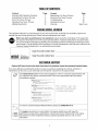
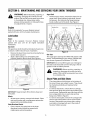
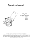
FINDINGMODELNUMBER
This Operator's Manual is an important part of your new snow thrower. It will help you assemble, prepare and
maintain the unit for best performance. Please read and understand what it says.
Before you start assembling your new equipment, please locate the model plate on the equipment
and copy the information from it in the space provided below. A sample model plate is also given below.
You can locate the model plate by standing at the operating position and looking down at the rear of the
snow thrower. This information will be necessary to use the manufacturer's web site and/or help from the
Customer Support Department or an authorized service dealer.
Copy the model number here:
P. O. BOX
361131
MTDLLC
_'_
CLEVELAND,OH
330-228-4683
_, www.rntuprouucts,com
Copy the serial number here:
44136
888-888-7318
CUSTOMER
SUPPORT
Please doNOT returnthe unit to the retailer from where it waspurchased, withoutfirst contactingCustomerSupport.
If you have difficulty assembling this product or have any questions regarding the controls, operation or
maintenance of this unit, you can seek help from the experts. Choose from the options below:
Visit mtdproducts.com for many useful suggestions. Click on Customer Support button and
you will get the four options reproduced here. Click on the appropriate button and help is
immediately available.
_4_lleje
{idlic[
"_o÷a_c_
keyw{,HL
*>_ll kl_>wb!d_le
_ ihh_se
base,
"
8RSWeY
pnfi_e
_Ser
_Y&_?
/ook/ng for cou/d be just
a mouse-crick aw_y!
vice Locato
at_tbo_ize_
Manuals
_ ÷_vi£e
cel_t÷_s
b_ yl}l_
¢,_ea,
On_in°
To reach a Customer Support Representative, please call 1(800) 800-7310.
The engine manufacturer is responsible for all engine-related issues with regard to
power-rating, specifications, warranty and service. Please refer to the engine
manufacturer's Owner's/Operator's Manual, packed separately with your unit, for more
information.
I Eng,no
I performance,
Manual
/
SECTION1: IMPORTANT
SAFEOPERATION
PRACTICES
WARNING:
Engine Exhaust, some of its constituents,
contain or emit chemicals known to the State of California
other reproductive harm.
and certain vehicle components
to cause cancer, birth defects or
DANGER:
This machine was built to be operated according to the rules for safe operation in this
manual. As with any type of power equipment, carelessness or error on the part of the operator can
result in serious injury. This machine is capable of amputating hands and feet and throwing objects.
Failure to observe the following safety instructions could result in serious injury or death.
Training
1. Read, understand, and follow all instructions on the
machine and in the manual(s) before attempting to
assemble and operate. Keep this manual in a safe
place for future and regular reference and for
ordering replacement parts.
2. Be familiar with all controls and their proper
operation. Know how to stop the machine and
disengage them quickly.
3. Never allow children under 14 years old to operate
this machine. Children 14 years old and over
should read and understand the operation
instructions and safety rules in this manual and
should be trained and supervised by a parent.
4. Never allow adults to operate this machine without
proper instruction.
5. Thrown objects can cause serious personal injury.
Plan your snow-throwing pattern to avoid discharge
of material toward roads, bystanders and the like.
6. Keep bystanders, helpers, pets and children at
least 75 feet from the machine while it is in
7.
operation. Stop machine if anyone enters the area.
Exercise caution to avoid slipping or falling,
especially when operating in reverse.
Preparation
1. Thoroughly inspect the area where the equipment
is to be used. Remove all doormats, newspapers,
sleds, boards, wires and other foreign objects,
which could be tripped over or thrown by the auger/
impeller.
2. Always wear safety glasses or eye shields during
operation and while performing an adjustment or
repair to protect your eyes. Thrown objects which
ricochet can cause serious injury to the eyes.
3. Do not operate without wearing adequate winter
outer garments. Do not wear jewelry, long scarves
or other loose clothing, which could become
entangled in moving parts. Wear footwear which
will improve footing on slippery surfaces.
4. Use a grounded three-wire extension cord and
receptacle for all units with electric start engines.
5.
6,
7.
,
,
Adjust collector housing height to clear gravel or
crushed rock surfaces.
Disengage all controls before starting the engine.
Never attempt to make any adjustments while
engine is running, except where specifically
recommended in the operator's manual.
Let engine and machine adjust to outdoor
temperature before starting to clear snow.
To avoid personal injury or property damage use
extreme care in handling gasoline. Gasoline is
extremely flammable and the vapors are explosive.
Serious personal injury can occur when gasoline is
spilled on yourself or your clothes, which can ignite.
Wash your skin and change clothes immediately.
a. Use only an approved gasoline container.
b. Extinguish all cigarettes, cigars, pipes and
other sources of ignition.
c. Never fuel machine indoors.
d.
e.
f.
g.
h.
i.
j.
Never remove gas cap or add fuel while the
engine is hot or running.
Allow engine to cool at least two minutes
before refueling.
Never over fill fuel tank. Fill tank to no more
than V2inch below bottom of filler neck to
provide space for fuel expansion.
Replace gasoline cap and tighten securely.
If gasoline is spilled, wipe it off the engine
and equipment. Move machine to another
area. Wait 5 minutes before starting the
engine.
Never store the machine or fuel container
inside where there is an open flame, spark or
pilot light (e.g. furnace, water heater, space
heater, clothes dryer etc.).
Allow machine to cool at least 5 minutes
before storing.
Operation
18. Neverputyourhandinthedischarge
orcollector
openings.
Alwaysusetheclean-out
toolprovided
to
1. Donotputhandsorfeetnearrotatingparts,inthe
unclogthedischarge
opening.Donotunclogchute
auger/impeller
housing
or chuteassembly.
Contact
assemblywhileengineisrunning.Shutoffengine
withtherotatingpartscanamputate
handsand
feet.
andremainbehindhandlesuntilallmovingparts
havestoppedbeforeunclogging.
2. Theauger/impeller
controlisasafetydevice.Never
andaccessories
approved
bypassitsoperation.
Doingso makesthemachine 19. Useonlyattachments
bythemanufacturer
(e.g.wheelweights,tire
unsafeandmaycausepersonal
injury.
chains,cabsetc.).
3. Thecontrolsmustoperateeasilyinbothdirections
andautomatically
returntothedisengaged
position 20. Ifsituationsoccurwhicharenotcoveredinthis
whenreleased.
manual,usecareandgoodjudgment.
Contactyour
dealerorcall1-800-800-7310
forassistance
and
4. Neveroperatewitha missingordamagedchute
thenameofyournearestservicingdealer.
assembly.
Keepallsafetydevicesinplaceand
working.
Maintenance& Storage
5. Neverrunanengineindoorsor ina poorly
1. Never tamper with safety devices. Check their
ventilatedarea.Engineexhaustcontainscarbon
proper operation regularly. Refer to the
monoxide,
anodorlessanddeadlygas.
maintenance and adjustment sections of this
6. Donotoperatemachinewhileundertheinfluence
manual.
ofalcoholordrugs.
2. Before cleaning, repairing, or inspecting machine
7. Mufflerandenginebecomehotandcancausea
disengage all controls and stop the engine. Wait
burn.Donottouch.
until the auger/impeller come to a complete stop.
8. Exerciseextremecautionwhenoperating
onor
Disconnect the spark plug wire and ground against
crossinggravelsurfaces.Stayalertforhidden
the engine to prevent unintended starting.
hazardsortraffic.
3. Check bolts and screws for proper tightness at
9. Exercise
cautionwhenchangingdirectionand
frequent intervals to keep the machine in safe
whileoperating
onslopes.
working condition. Also, visually inspect machine
10. Planyoursnow-throwing
patterntoavoiddischarge
for any damage.
towardswindows,
walls,carsetc.Thus,avoiding
4. Do not change the engine governor setting or overpossiblepropertydamageorpersonalinjury
speed the engine. The governor controls the
causedbya ricochet.
maximum safe operating speed of the engine.
11. Neverdirectdischarge
atchildren,bystanders
and
5. Snow thrower shave plates and skid shoes are
petsorallowanyoneinfrontofthemachine.
subject to wear and damage. For your safety
12. Donotoverloadmachinecapacitybyattempting
to
protection, frequently check all components and
clearsnowattoofastofa rate.
replace with original equipment manufacturer's
13. Neveroperatethismachinewithoutgoodvisibility
(OEM) parts only. "Use of parts which do not meet
orlight.Alwaysbesureofyourfootingandkeepa
the original equipment specifications may lead to
firmholdonthehandles.Walk,neverrun.
improper performance and compromise safety!"
14. Disengage
powertotheauger/impeller
when
6. Check controls periodically to verify they engage
transporting
ornotinuse.
and disengage properly and adjust, if necessary.
15. Neveroperatemachine
athightransportspeedson
Refer to the adjustment section in this operator's
slipperysurfaces.Lookdownandbehindanduse
manual for instructions.
carewhenbackingup.
7. Maintain or replace safety and instruction labels, as
16. Ifthemachineshouldstarttovibrateabnormally,
necessary.
stoptheengine,disconnect
thesparkplugwireand 8. Observe proper disposal laws and regulations for
grounditagainsttheengine.Inspectthoroughly
for
gas, oil, etc. to protect the environment.
damage.Repairanydamagebeforestartingand
9. Prior to storing, run machine a few minutes to clear
operating.
snow from machine and prevent freeze up of auger/
17. Disengage
allcontrolsandstopenginebeforeyou
impeller.
leavetheoperating
position(behindthehandles).
10. Never store the machine or fuel container inside
Waituntiltheauger/impeller
comestoa complete
where there is an open flame, spark or pilot light
stopbeforeunclogging
thechuteassembly,
making
such as a water heater, furnace, clothes dryer etc.
anyadjustments,
or inspections.
11. Always refer to the operator's manual for proper
instructions on off-season storage.
YOURRESPONSIBILITY
Restrict the use of this power machine to persons who read, understand and follow the warnings and instructions in
this manual and on the machine.
Do not modifyengine
To avoid serious injury or death, do not modify engine
in any way. Tampering with the governor setting can
lead to a runaway engine and cause it to operate at
unsafe speeds. Never tamper with factory setting of
engine governor.
NoticeregardingEmissions
Engines which are certified to comply with California
and federal EPA emission regulations for SORE (Small
Off Road Equipment) are certified to operate on regular
unleaded gasoline, and may include the following
emission control systems: Engine Modification (EM)
and Three Way Catalyst (TWC) if so equipped.
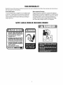
SAFETYLABELSFOUNDONYOURSNOWTHROWER
1.KEEPAWAYFROMROTATING
IMPELLER
ANDAUGER.CONTACT
WITHIMPELLER
OR
AUGERCANAMPUTATE
HANDSANDFEET.
2. USECLEAN-OUT
TOOLTO UNCLOG
DISCHARGE
CHUTE.
3. DISENGAGE
CLUTCH
LEVERS,
STOPENGINE,
ANDREMAINBEHINDHANDLES
UNTILALL
MOVINGPARTSHAVESTOPPED
BEFORE
UNCLOGGING
OR SERVICINGMACHINE.
4. TO AVOIDTHROWNOBJECTSINJURIES,
NEVER
DIRECT
DISCHARGE
ATBYSTANDERS.
USEEXTRA
CAUTION
WHENOPERATING
ON
GRAVELSURFACES.
5. READOPERATOR'SMANUAL.
CLEAN-OUT TOOL I1_
SECTION2: ASSEMBLING
YOURSNOWTHROWER
........./t_ ........
NOTE:
References to right or left side of the snow
thrower are determined from behind the unit in the
operating position (standing directly behind the snow
thrower, facing the handle panel).
NOTE:
This Operator's Manual covers several
models. Snow thrower features vary by model Not
all features referenced and pictured in this manual are
applicable to all snow thrower models.
IMPORTANT: Two replacement auger shear pins and
cotter pins are included with this manual. Refer to
Augerson page 19 for more information.
CAUTION: Prior to operating your snow
thrower, refer to AugerCentrelTeston page 11.
Read and follow all instructions carefully and
perform all adjustments to verify your snow
thrower is operating safely and properly.
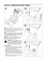
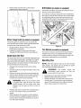
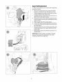
Securing the Handle
1. Observe the lower rear area of the snow thrower to
2.
3.
4.
be sure both cables are aligned with roller guides
before pivoting the handle upward.
Secure the upper shift rod to the lower shift rod by
sliding the connector sleeve downward.
Secure the right side of the handle by tightening the
plastic wing knob. Remove and discard any rubber
bands, if present. They are for packaging purposes
only.
Secure the left side of the handle by tightening the
plastic wing knob into the eyebolt.
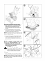
Attachingthe Chute Assemblyand DirectionalControl
1.
Apply a lubricant (i.e. 3-in-1 oil) to the rim of the
chute base (and the underside of the chute
assembly) and position the chute assembly over
the base.
2.
Close the flange keepers to secure the chute
assembly to the chute base. The flange keepers
will click into place when properly secure.
NOTE:
If the flange keepers wifl not easily click into
place, use the palm of your hand to apply swift, firm
pressure to the back of each.
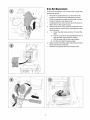
,
Remove the flat washer and hairpin clip from the
end of the chute directional control. Insert the end
of the chute directional control into the lower
bracket and secure with the flat washer and hairpin
clip just removed.
NOTE:
If necessary, the lower bracket can be
adjusted. Refer to ChuteBracketAdjustment.
on Page 14.
4.
If equipped, slip the cables, running from the
handle panel to the chute assembly, into the cable
guide located on top of the engine.
CAUTION: Prior to operating your snow
thrower, refer to AugerControlTeston page 11.
Read and follow all instructions carefully and
perform all adjustments to verify your snow
thrower is operating safely and properly.
Tire Pressure
•
Before operating, check tire pressure and reduce
pressure in both tires to between 15 psi and 20 psi.
NOTE:
If the tire pressure is not equal in both tires,
the unit may not travel in a straight path and the shave
plate may wear unevenly.
Cable
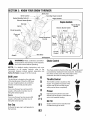
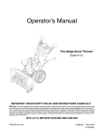
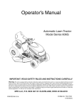
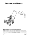
SECTION3: KNOWYOURSNOWTHROWER
/4
Shift Lever
Drive Control
Chute Controlt
Heated Handles Switcht
Control
Electric Starter Button
f
EngineControls
Gas
Recoil Starter
Handle
Oil Fill
Electric Starter Outlet
Chute Assembly
\
Clean-out
Tool
Chute Directional
Control
Ignition
Key
Control
Throttle
Control
Shoe
Augers
tlf Equipped
ChokeControl
_,
all
instructions and
warnings
on theand
machine
WARNING:
Read,
understand,
follow
and in this manual before operating.
NOTE:
For detailed starting instructions and more
information on all engine controls,
refer to the
Tecumseh Engines manual packed separately and
StartingThe Engineon page 10 of this manual.
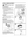
ShiftLever
6
The shift lever is located on the right side
of the handle panel. Place the shift lever
into any of eight positions to control the
ThrottleControl
The throttle control is located on the
direction of travel and ground speed.
Forward
=,t
Your snow thrower has six forward (F)
speeds, with position number one (1)
being the slowest speed.
U
Reverse
Your snow thrower has two reverse (R)
speeds, with position number one (1)
being the slower speed.
_
GasCap
R1
Unthread the gas cap to add gasoline to
the fuel tank.
The choke control is found on the rear of the engine and
is activated by rotating the knob clockwise. Activating
the choke control closes the choke plate on the
carburetor and aids in starting the engine.
engine. It regulates the speed of the
engine and will shut off the engine
when pushed down completely.
Primer
Depressing the primer forces fuel
directly into the engine's carburetor to
aid in cold-weather starting.
F 1
Oil Fill
R2
Engine oil level can be checked and
oil added through the oil fill.
AugerControl
s
Two-WayChuteControl(ifEquipped)
f
AUGER
CONTROL
_
CHUTE
DiRECTiONAL
CONTROL
BISCHARGE_JBISCHARGE
--
#
The auger control is located on the left handle.
Squeeze the control grip against the handle to engage
the augers and start snow throwing action. Release to
stop.
DriveControl
J
=
CHUTETiLT
UP
The two-way chute control is meant to control the
distance of snow discharge from the chute.
•
To change the angle/distance which snow is
thrown, pivot the joy-stick forward or backward.
IgnitionKey
DRIVE
The ignition key must be inserted and snapped in place
in order for the engine to start. Remove the ignition key
to prevent unauthorized use of equipment.
CONTROL
IMPORTANT:Do not turn the ignition key in an attempt
to start the engine. Doing so may cause it to break.
Clean-OutTool
WARNING:
Never use your hands to clear
a clogged chute. Shut off engine and remain
behind handles until all moving parts have
stopped before unclogging. Use the cleanout tool or a stick to unclog.
J
The drive control is located on the right handle.
Squeeze the control grip against the handle to engage
the wheel drive. Release to stop.
ChuteDirectionalControl
f
CHUTE
DiRECTiONAL
CONTROL
DISCHARGE
LEFT
The clean-out tool is fastened to the top of the auger
housing with a mounting clip. The tool is designed to
clear a clogged chute. Refer to Operating
YourSnow
Thrower section for more detailed information regarding
the clean-out tool.
NOTE:
This item is fastened with a cable tie to the
rear of the auger housing at the factory. Cut the cable
tie before operating the snow thrower.
HeatedHandlesSwitch(ifEquipped)
$
The chute directional
the snow thrower.
control is located on left side of
To change the direction in which snow is thrown, turn
chute directional control as follows:
•
Crank clockwise to discharge to the left.
•
Crank counterclockwise
to discharge to the right.
To change the distance of snow discharge from the
chute, refer to the Making Adjustments section on
page 13.
This switch is located on the right side of the snow
thrower dash panel. To activate the heated handles,
toggle the switch to the right to generate heat within the
handle grips. Toggle the switch to the left to the OFF
position after using the snow thrower.
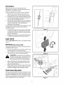
SkidShoes(stylevaries by model)
Position the skid shoes based on surface conditions.
Adjust upward for hard-packed snow. Adjust downward
when operating on gravel or crushed rock surfaces.
SECTION4: OPERATING
YOURSNOWTHROWER
BeforeStarting
WARNING:
If your home electrical
system is grounded, but a three-hole
receptacle is not available, do not use your
snow thrower's electric starter.
all instructions and
WARNING"
Read,warnings
understand,
on theand
machine
follow
and in this manual before operating.
If you have a grounded three-prong receptacle,
proceed as follows:
Gas& OilFill-Up
•
Service the engine with gasoline and oil as instructed in
the Tecumseh Engines manual packed separately with
your snow thrower. Read instructions carefully.
WARNING:
•
Use extreme care when
handling gasoline. Gasoline is extremely
flammable and the vapors are explosive.
Never fuel the machine indoors or while the
engine is hot or running. Extinguish cigarettes,
cigars, pipes and other sources of ignition.
•
NOTE:
If the engine is already warm, place choke
control in the OFF position instead of FULL.
•
A small plastic cup may be located inside the fuel fill
opening beneath the gas cap. Remove and discard
this cup before filling up the tank.
•
•
Push the primer two or three times for cold engine
start, making sure to cover vent hole in the center of
the primer when pushing.
NOTE: DO NOT use primer to restart a warm engine
after a short shutdown.
StartingThe Engine
•
Plug the extension cord into the outlet located on
the engine's surface. Plug the other end of
extension cord into a three-prong 120-volt,
grounded, AC outlet in a well-ventilated area.
Rotate choke control to FULL choke position (cold
engine start).
Attach spark plug wire to spark plug. Make certain
the metal loop on the end of the spark plug wire
(inside the boot) is fastened securely over the metal
tip on the spark plug.
Make certain both the auger control and drive
control are in the disengaged (released) position.
Move throttle control up to FAST position. Insert
ignition key into slot. Make sure it snaps into place.
Do not attempt to turn the key.
•
•
Push starter button to start engine.
Once the engine starts, immediately release starter
button.
•
As the engine warms, slowly rotate the choke
control to the OFF position. If the engine falters,
quickly rotate the choke control back to FULL and
then slowly into the OFF position again.
When disconnecting the extension cord, always
unplug the end at the three-prong wall outlet before
unplugging the opposite end from the snow
thrower.
•
NOTE:
The engine cannot start unless the key is
inserted into ignition switch.
RecoilStarter
•
Electric Starter (on models so quipped)
•
Determine that your home's wiring is a three-wire
grounded system. Ask a licensed electrician if you
are not certain.
Rotate choke control to FULL choke position (cold
engine start).
NOTE:
If the engine is already warm, place choke
control in the OFF position instead of FULL.
•
CAUTION:
If your home's wiring system
is not a three-wire grounded system, do
not use this electric starter under any
conditions.
Push the primer two or three times for cold engine
start, making sure to cover vent hole in the center of
the primer when pushing.
NOTE: DO NOT use primer to restart a warm engine
after a short shutdown.
WARNING:
The optional electric starter is
equipped with a grounded three-wire power
cord and plug, and is designed to operate on
120 volt AC household current. It must be
used with a properly grounded three-prong
receptacle at all times to avoid the possibility
of electric shock. Follow all instructions
carefully prior to operating the electric starter.
NOTE:
Additional priming may be necessary if the
temperature is below 15° Fahrenhe#.
10
•
Grasp the recoil starter handle and slowly pull the
rope out. At the point where it becomes slightly
harder to pull the rope, slowly allow the rope to
recoil.
•
Pull the starter handle with a firm, rapid stroke.
IMPORTANT: Do not release the handle and allow it to
snap back. Keep a firm hold on the starter handle and
allow it to slowly recoil.
•
ToEngageDrive
•
As the engine warms, slowly rotate the choke
control to the OFF position. If the engine falters,
quickly rotate the choke control back to the FULL
position and then slowly into the OFF position
again.
IMPORTANT:Use the slower speeds until you are
comfortable and familiar with the operation of the snow
thrower.
StoppingTheEngine
•
•
Run engine for a few minutes before stopping to
help dry off any moisture on the engine.
To help prevent possible starter freeze-up, proceed
as follows:
•
3.
4.
5.
6.
IMPORTANT: NEVER reposition the shift lever (change
speeds or direction of travel) without first releasing the
drive control and bringing the snow thrower to a
complete stop. Doing so will result in premature wear to
the snow thrower's drive system.
on the engine, then to 120 volt AC outlet.
With the engine running, push the starter button
and allow the starter for spin for several seconds.
The noise made by the starter is normal. The
engine's starter is not being harmed.
When disconnecting the extension cord, always
unplug the end at the three-prong wall outlet before
unplugging the opposite end from the snow
thrower.
ToEngageAugers
•
IMPORTANT: Perform the following test before
operating your snow thrower for the first time and at the
start of each winter season.
Check the adjustment of the auger control as follows:
•
•
The engine
RecoilStarter
1.
2.
3.
With engine running, pull starter rope with a rapid,
continuous full arm stroke three or four times.
•
Pulling the starter rope will produce a loud
clattering sound, which is not harmful to engine.
Move throttle control to STOP position.
Remove the ignition key.
•
NOTE:
Keep the key in a safe place.
cannot start without the ignition key.
.
To engage the augers and start throwing snow,
squeeze the auger control against the left handle.
Release to stop the augers.
Auger Control Test
Move throttle control to STOP position.
Remove the ignition key.
Wipe all snow and moisture from the carburetor
cover in the area of the drive control and auger
control. Also, engage and release the controls
several times.
NOTE:
Keep the key in a safe place.
cannot start without the ignition key.
Squeeze the drive control against the handle the
snow thrower will move. Release it and drive
motion will stop.
Electric Starter (on models so equipped)
1. Connect extension cord to the electric starter outlet
2.
Move shift lever into one of the six forward (F)
positions or two reverse (R) positions. Select a
speed appropriate for the snow conditions and a
pace you're comfortable with.
•
The engine
•
Wipe all snow and moisture from the carburetor
cover in the area of the drive control and auger
control. Also, engage and release the controls
several times.
When the auger control is released and in the
disengaged "up" position, the cable should have
very little slack. It should NOT be tight.
In a well-ventilated area, start the snow thrower
engine as instructed earlier in this section under the
heading Startingthe Engine.Make sure the throttle is
set in the FAST position.
While standing in the operator's position (behind
the snow thrower), engage the auger.
Allow the auger to remain engaged for
approximately ten (10) seconds before releasing
the auger control. Repeat this several times.
With the throttle control in the FAST (rabbit)
position and the auger control in the disengaged
"up" position, walk to the front of the machine.
Confirm that the auger has completely stopped
rotating and shows NO signs of motion.
IMPORTANT: If the auger shows ANY signs of rotating,
immediately return to the operator's position and shut
off the engine. Wait for ALL moving parts to stop before
re-adjusting the auger control.
•
•
•
11
To readjust the control cable, loosen the hex jam
nut on the auger control cable "Z" fitting.
Rotate the coupling end of the cable
counterclockwise to provide more slack.
Retighten the hex jam nut. See Figure 1.
•
Repeat Auger Control Test to verify proper
adjustment has been achieved.
Drift Cutters(onmodelssoequipped)
Drift cutters should be used when operating the snow
thrower in heavy drift conditions.
On models so equipped, drift cutters are assembled to
the auger housing inverted. Remove the carriage bolts
by unthreading the hex nuts which secure them, and
reinstall the drift cutters in their proper position before
operating the snow thrower. See Figure 2.
J
Figure 1
Drive/ AugerLock(onmodelssoequipped)
The drive/auger lock allows the user to operate the
snow thrower with one hand, leaving the left hand free
to operate the chute directional control.
•
Engage both the Auger Control and the Drive
Control at the same time.
•
Release the Auger Control and it will remain
engaged until the Drive Control is also released.
Carriage Screws /
Hex Nuts
Figure 2
Tire Chains(onmodelssoequipped)
Tire chains should be used whenever extra traction is
needed. If your unit is not equipped with tire chains,
contact Customer Support as instructed on page 2 for
information regarding price and availability.
ChuteClean-OutTool
The chute clean-out tool is conveniently fastened to the
rear of the auger housing with a mounting clip. Should
snow and ice become lodged in the chute assembly
during operation, proceed as follows to safely clean the
chute assembly and chute opening:
•
•
•
•
OperatingTips
NOTE: Allow the engine to warm up for a few minutes
after starting. The engine will not develop full power
until it reaches operating temperature.
Release both the Auger Control and the Drive
Control.
Stop the engine by moving the throttle control to the
stop position.
Remove the clean-out tool from the mounting clip.
Use the shovel-shaped end of the clean-out tool to
dislodge and scoop any snow and ice which has
formed in and near the chute assembly.
,_
surrounding
areas
and and
can
WARNING:
The become
muffler, hot
engine
cause a burn. Do not touch.
Discharge snow downwind whenever possible.
Slightly overlap each previous swath.
Set the skid shoes 1/4" below the scraper bar for
normal usage. The skid shoes may be adjusted
upward for hard-packed snow. Adjust downward
when using on gravel or crushed rock.
WARNING:
Never use your hands to clear
a clogged chute. Shut off engine and remain
behind handles until all moving parts have
stopped. Use the clean-out tool or a stick to
unclog.
Refasten the clean-out tool to the mounting clip on
the rear of the auger housing, and restart the
engine.
While standing in the operator's position (behind
the snow thrower), engage the auger control for a
few seconds to clear any remaining snow and ice
from the chute assembly.
12
SECTION5: MAKINGADJUSTMENTS
•
adjustments while
WARNING:
Nevertheattempt
engineto ismake
running,
any
except where specified in operator's manual.
•
ShiftRodAdjustment
•
If the full range of speeds (forward and reverse) cannot
be achieved, refer to the figures marked 1,2, and 3 to
the right and adjust the shift rod as follows:
1.
2.
3.
Using a W' wrench, loosen the upper and lower hex
nuts found on one cable adjuster.
Grasp the metal cable housing and gently push
upward to take up slack (usually no more than 1/4inch) in the cable before retightening both hex nuts.
Repeat on each of two cable adjusters until the
upper chute has full range in both directions.
Place the shift lever in the fastest forward speed
position. Remove the hairpin clip which secures the
ferrule to the shift lever.
Rotate the shift arm counter-clockwise as far as it
will go.
Thread the ferrule up or down the shift rod until it
aligns with the hole in the shift lever behind the
handle panel. Resecure the ferrule with the hairpin
clip removed earlier.
Tire Pressure
•
Figure 4
Before operating, check tire pressure and reduce
pressure to between 15 psi and 20 psi.
NOTE:
/f the tire pressure is not equa/ in both tires,
the unit may pu// to one side or the other.
ChuteAssembly
The distance snow is thrown can be adjusted by
changing the angle of the chute assembly. To do so,
stop the engine by removing the ignition key and loosen
the plastic wing knob found on the left side of the chute
assembly. Pivot the chute upward or downward before
re-tightening the wing knob. See Figure 3.
Figure 3
Joy-StickCableAdjustment(ifEquipped)
If the upper chute does not have full range upward-anddownward, the joy-stick cables can be adjusted to take
up slack. See Figure 4.
13
DriveControl
When the drive control is released and in the
disengaged "up" position, the cable should have very
little slack. It should NOT be tight.
Check the adjustment of the drive control as follows:
1.
2.
3.
With the drive control released, push the snow
thrower gently forward. The unit should roll freely.
Engage the drive control and gently attempt to push
the snow thrower forward. The wheels should not
turn. The unit should not roll freely.
With the drive control released, move the shift lever
back and forth between the R2 position and the F6
position several times. There should be no
resistance in the shift lever.
If any of the above tests failed, the drive cable is in need
of adjustment, refer to the figure at the right and
proceed as follows:
•
•
Figure 5
Loosen the hex jam nut on the auger control cable
"Z" fitting and rotate the coupling end of the cable
downward to provide more slack or upward to take
up slack. See Figure 5.
Retighten the hex jam nut and repeat all three tests
to verify proper adjustment has been achieved.
AugerControl
Refer to AugerControlTeston Page 11 to adjust the auger
control.
SkidShoes(stylevaries by model)
The space between the skid shoes and the ground can
be adjusted. See Figure 6.
•
•
For close snow removal on a smooth surface, raise
skid shoes higher on the auger housing.
Use a middle or lower position when the area to be
cleared is uneven, such as a gravel driveway.
Figure 6
CAUTION:
Loose gravel can be picked up
and thrown by the auger, causing injury to the
operator and bystanders and/or damage to
the snow thrower and surrounding property.
•
•
Adjust skid shoes by loosening the four hex nuts
(two on each side) and carriage bolts. Move skid
shoes to desired position.
Make certain the entire bottom surface of skid shoe
is against the ground to avoid uneven wear on the
skid shoes. Retighten nuts and bolts securely.
ChuteBracketAdjustment
If the spiral at the bottom of the chute directional control
is not fully engaging with the chute assembly, the chute
bracket can be adjusted. To do so, loosen the two nuts
which secure the chute bracket and reposition it slightly
before retightening the nuts. See Figure 7.
r
Figure 7
14
SECTION6: MAINTAININGANDSERVICING
YOURSNOWTHROWER
WARNING:
Before lubricating, repairing, or
inspecting, disengage all controls and stop
engine. Wait until all moving parts have come
to a complete stop. Always wear safety
glasses during operation or while performing
any adjustments or repairs.
Auger Shaft
•
At least once a season, remove the shear pins on
auger shaft. Spray lubricant inside shaft, around
the spacers. Also lubricate the flange bearings
found at either end of the shaft. See Figure 9.
i
Engine
Shear Pin
I
Spacers
I
Bearing
Refer to the separate Tecumseh Engines manual
packed with your unit for all engine maintenance.
Lubrication
Engine
Refer to the separate Tecumseh Engines manual
packed with your unit for all engine lubrication
instructions.
GearShaft
The gear (hex) shaft should be lubricated at least once
a season or after every 25 hours of operation.
•
Remove the lower frame cover by removing the two
screws which secure it.
•
Apply a light coating of an all-weather multipurpose grease to the hex shaft. See Figure 8.
Figure 9
GearCase
The auger gear case has been filled with grease at the
factory. If disassembled for any reason, lubricate with
two ounces of grease (Part Number 737-0168).
oi
IMPORTANT:Do not overfill the gear case. Damage to
the seals could result. Be sure the vent plug is free of
grease in order to relieve pressure.
WARNING:
Before servicing, repairing, or
inspecting, disengage all controls and stop
engine. Wait until all moving parts have come
to a complete stop.
\
\
ShavePlateandSkidShoes
•
•
Figure 8
IMPORTANT: Keep lubricant off the friction wheel and
drive plate.
Wheels
•
•
At least once a season, remove both wheels. Clean
and coat the axles with a multipurpose automotive
grease before reinstalling wheels.
ChuteDirectionalControl
•
Once a season, the spiral end on the chute
directional control should be greased with
multipurpose automotive grease.
15
The shave plate and skid shoes on the bottom of
the snow thrower are subject to wear. They should
be checked periodically and replaced when
necessary.
To remove skid shoes, remove the four carriage
bolts and hex flange nuts which secure them to the
snow thrower. Reassemble new skid shoes with the
four carriage bolts (two on each side) and hex
flange nuts. Refer to Figure 6.
To remove shave plate, remove the carriage bolts
and hex nuts which attach it to the snow thrower
housing. Reassemble new shave plate, making
sure heads of carriage bolts are to the inside of
housing. Tighten securely.
AugerBeltReplacement
To remove and replace your snow thrower's auger belt,
proceed as follows:
1.
•
•
2.
Remove the plastic belt cover on the front of the
engine by removing the two self-tapping screws.
Drain the gasoline from the snow thrower, or place
a piece of plastic under the gas cap.
Carefully pivot the snow thrower up and forward so
that it rests on the auger housing.
Remove the frame cover from the underside of the
snow thrower by removing four self-tapping screws
which secure it.
3.
4.
•
•
•
Roll the auger belt off the engine pulley.
Unhook the support bracket spring from the frame.
Loosen and remove the shoulder screw which acts
as a belt keeper.
Remove the belt from around the auger pulley, and
slip the belt between the support bracket and the
auger pulley
Reassemble auger belt by following instructions in
reverse order.
IMPORTANT: Do NOT forget to reinstall the shoulder
screw and reconnect the spring to the frame after
installing a replacement auger belt.
/!oi
16
DriveBeltReplacement
To remove and replace your snow thrower's auger belt,
proceed as follows:
1.
•
•
2.
Remove the plastic belt cover on the front of the
engine by removing the two self-tapping screws.
Drain the gasoline from the snow thrower, or place
a piece of plastic under the gas cap.
Carefully pivot the snow thrower up and forward so
that it rests on the auger housing.
Remove the frame cover from the underside of the
snow thrower by removing four self-tapping screws
which secure it.
3.
4.
•
a.
Grasp the idler pulley and pivot it toward the
right.
b. Insert a screw driverthrough aligning holes in
both the idler bracket and the engine.
c. Roll the auger belt off the engine pulley.
d. Lift the drive belt off engine pulley.
Slip the drive belt off the pulley and between friction
wheel and friction wheel disc.
Remove and replace belt in the reverse order.
/!oi
17
FrictionWheelRemoval
If the snow thrower fails to drive with the drive control
engaged, and performing the drive control cable
adjustment on page 14 fails to correct the problem, the
friction wheel may need to be replaced. Follow the
instructions below. Examine the friction wheel for signs
of wear or cracking and replace if necessary
•
•
•
1.
Place the shift lever in third Forward (F3) position.
Drain the gasoline from the snow thrower, or place
a piece of plastic under the gas cap.
Carefully pivot the snow thrower up and forward so
that it rests on the auger housing.
a. Remove the frame cover from the underside
of the snow thrower by removing four selftapping screws which secure it.
b. Remove the right-hand wheel by removing
the screw and bell washer which secure it to
the axle.
2.
c.
Locate the hex shaft and E-ring on the right
side of the snow thrower frame, about two
inches from the wheel axle.
c.
Using a suitable tool, carefully remove the
outer E-ring which secures the hex shaft to
the snow thrower frame and lightly tap the
shaft's end to dislodge the ball bearing from
the right side of the frame.
Slide the hex shaft downward and to the left
a.
while carefully un-meshing the lower gears
on the hex shaft from the upper gears on the
wheel axle.
b. Set the hex shaft's gears aside.
c. Carefully remove the inner E-ring from the
hex shaft and slide the friction wheel
assembly off the hex shaft.
NOTE:
If you're replacing the friction wheel assembly
as a whole, discard the worn part and sfide the new part
onto the hex shaft. Follow the steps above in reverse
order
to
reassemble
components.
If
you're
disassembling the friction wheel and replacing only the
rubber ring, proceed as follows:
3.
•
•
Remove the four screws which secure the friction
wheel's side plates together.
Remove the rubber ring from between the plates.
Reassemble the side plates with a replacement
rubber ring.
IMPORTANT:Tighten each screw only one rotation
before turning the wheel clockwise and proceeding with
the next screw. Repeat this process several times to
ensure the plates are secured with equal force.
•
Slide the friction wheel assembly back onto the hex
shaft and follow the steps above in reverse order to
reassemble components.
18
Augers
•
•
IMPORTANT:NEVER replace the auger shear pins with
anything other than OEM Part No.738-04124
replacement shear pins. Any damage to the auger
gearbox or other components as a result of failing to do
so will NOT be covered by your snow thrower's
warranty.
The augers are secured to the spiral shaft with two
shear pins and cotter pins. If the auger should strike
a foreign object or ice jam, the snow thrower is
designed so that the pins may shear.
Refer to Figure 9.
If the augers will not turn, check to see if the pins
have sheared. One set of replacement shear pins
has been provided with the snow thrower. When
replacing pins, spray an oil lubricant into shaft
before inserting new pins.
SECTION7: OFF-SEASON
STORAGE
WARNING:
Never store the machine or
•
fuel container indoors where there is an open
flame, spark or pilot light such as on a water
heater, furnace, clothes dryer or other gas
appliances.
NOTE:
Fuel stabilizers, such as STA-BIL®, are an
acceptable alternative in minimizing the formation of
fuel gum deposits during storage. Do not drain
carburetor if using a fuel stabilizer.
WARNING:
Drain fuel into an approved
container outdoors, away from open flame.
Allow engine to cool. Extinguish cigarettes,
cigars, pipes, and other sources of ignition
prior to draining fuel. Fuel left in engine for
extended period deteriorates and will cause
serious starting problems.
•
•
Wipe equipment with an oiled rag to prevent rust.
Remove spark plug and pour one ounce of engine
oil through spark plug hole into cylinder. Cover
spark plug hole with rag. Crank engine several
times to distribute oil. Replace spark plug.
•
Follow the lubrication recommendations found in
the Maintenance Section.
•
Always store the snow thrower in a clean, dry area.
When storing any type of power equipment in an
unventilated or metal storage shed, care should be
taken to rust proof the equipment. Using a light oil or
silicone, coat the equipment, especially any chains,
springs, bearings and cables.
If unit is to be stored over 30 days, prepare for storage
as follows:
•
•
Drain carburetor by pressing upward on bowl drain,
located below the carburetor cover.
Remove gasoline from carburetor and fuel tank to
prevent gum deposits from forming on these parts
and causing possible malfunction of engine.
Run engine until fuel tank is empty and engine
stops due to lack of fuel.
19
SECTION8: TROUBLE
SHOOTING
GUIDE
Trouble
Possible
Cause(s)
Engine fails to start
Fuel tank empty, or stale fuel.
Blocked fuel line.
Choke control not in ON position
Faulty spark plug.
Ignition key not present.
Spark plug wire disconnected.
Engine not primed.
Engine runs erratic
Loss of power
Engine overheats
Excessive vibration
Unit fails to propel itself
Unit fails to
discharge snow
Unit running on CHOKE.
Blocked fuel line or stale fuel.
Water or dirt in fuel system.
Carburetor out of adjustment.
Spark plug wire loose.
Gas cap vent hole plugged.
Exhaust port plugged.
Carburetor not adjusted
properly.
Loose parts or damaged auger.
Incorrect adjustment of drive
control cable.
Drive belt loose or damaged.
Chute assembly clogged.
Foreign object lodged in auger.
Incorrect adjustment of auger
control cable.
Drive belt loose or damaged.
Shear pin(s) sheared.
NOTE:
Corrective
Action
Fill tank with clean, fresh gasoline. Fuel will not last over thirty days
unless a fuel stabilizer is used.
Clean fuel line.
Move choke control to ON position
Clean, adjust gap or replace.
Insert key into ignition switch.
Connect spark plug wire.
Refer to the Tecumseh engine manual or Startingthe Engineon page
10 of this manual for instructions on the engine primer.
Move choke control to OFF position.
Clean fuel line; fill tank with clean fresh gasoline. Fuel will not last
over thirty days unless a fuel stabilizer is used.
Drain fuel tank. Refill with fresh fuel.
Refer to the Tecumseh engine manual.
Connect and tighten spark plug wire.
Remove ice and snow from cap. Be certain vent hole is clear.
Clean following the engine manual.
Refer to the Tecumseh engine manual packed with your unit or
have carburetor adjusted by an authorized service dealer.
Stop engine immediately and disconnect spark plug wire. Tighten
all bolts and nuts. Make all necessary repairs. If vibration
continues, have unit serviced by an authorized service dealer.
Adjust drive control cable.
Replace drive belt.
Stop engine immediately. Clean chute assembly and inside of
auger housing with chute clean-out tool or stick.
Stop engine immediately. Remove object from auger with clean-out
tool or stick.
Adjust auger control cable.
Replace drive belt.
Replace shear pin(s).
For repairs beyond the minor adjustments above, contact your local authorized service dealer.
20
NOTES
21
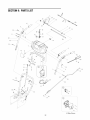
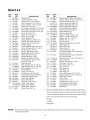
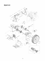
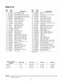
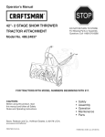
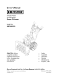
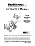
SECTION9: PARTSLIST
25
18b
9 _..
//
13
/
28_,.
///
_ ..........
55
56<:T_
/
8
......._
/
/
66 .............................................................
/
48
_
16
_(_
58
.........
57
18a
4O
/
/
/
/
/
/
/
i\
41
2O
0
_59
51
_." .....64
'14
/
/
/
/
K-Style Shown
22
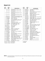
StylesH & K
REF.
PART
NO.
NO.
1
631-04125
631-04128
631-04133
631-04134
4
5
6
7
8
9
10
11
12
13
14
15a
15b
16
17
18a
18b
19
2O
21
22
23
24
25
26
27
28
29
30
31
684-04105
684-04106
710-04326
710-04354
710-1026
710-1233
711-04287
711-0677
712-04064
712-04081A
714-0104
720-0274
725-1757t
720-04039
725-04213
725-04214
725-04216At
725-1649
726-0470t
731-04894
731-04896
732-0193
732-04219
732-04238
735-0199A
736-0262
738-04122
738-04125
746-0778
747-04284
REF.
DESCRIPTION
Panel Assembly, Handle, H-Style*
(Inc. Ref. 47)
Panel Assembly, Handle, K-Style*
(Inc. Ref. 47)
Handle Assembly, Clutch Lock, LH
(Inc. Ref. 48)
Handle Assembly, Clutch Lock, RH
(Inc. Ref. 48)
Handle Assembly, Engagement, LH
Handle Assembly, Engagement, RH
Screw, #8-16 x.50
Screw, 1/4-20 x.375
Screw, Self-tapping, 1/4-20 x 1.750
Screw, Machine, #10-24 x 1.375
Rod, Pivot
Ferrule, 5/16-18 x.312
Nut, Flange Lock, Nylon, 1/4-20
Nut, Shoulder, Hex, 1/4-20,
Pin, Cotter,.072 Dia. x 1.13
Grip, 1.0 ID x 5.0
Heated Grip
Knob, Shift
Lamp
Harness, w/o Heated Grips
Harness, Heated Grips
Socket, Lamp
Tie, Cable, 19 x 8.39", Tree Mount
Plate, Lock
Cam, Clutch Lock
Spring, Compression,.39 x.60 x.88
Spring, Clutch, Lock
Spring, Torsion, 0.8156 ID x.3038
Bumper, Rubber,.62 OD x.22
Washer, Flat,.385 x.870 x.092
Screw, Shoulder,.437 x 1.345, 1/4-20
Screw, Shoulder,.374 Dia. x 1.05
Z-Fitting, Cable
Rod, Shift,.312 x 9.0 Upper
* Example of H-Style: 31AE6FHG705
* Example of K-Style: 31AE6GKG731
NOTE:
Snow thrower features and components
are standard equipment.
NO.
32
33
34
35
36
37
38
39
40
41
42
43
44
45
46
47
48
49
5O
51
52
53
54
55
56
57
58
59
6O
61
62
63
64
65
66
PART
NO.
750-04314
790-00130
790-00140
710-0449
710-0726
720-0284
736-0451
749-04138
749-04141
749-04190t
749-04142
749-04191t
712-04063
726-0135
732-04205
736-3015
747-04257
731-04864
712-0161
684-04117tt
790-00131tt
710-04187tt
753-04862tt
753-04864tt
710-0837t
712-0693t
716-0398t
725-1756t
736-0226t
738-04135tt
684-04104
720-0201A
726-0100
735-0234
736-0185
747-04263
736-0463
DESCRIPTION
Connector Sleeve, Shift Rod
Lever, Shift
Bracket, Panel
Screw, Carriage, 5/16-18, 2.25, Gr5
Screw, 5/16-12, 0.750
Wing Knob, 5/16-18
Washer, Saddle, 320 x.93 x.060
Handle, Lower, Snow
Handle, Upper, RH
Handle, Upper, RH (For Heated Grips)
Handle, Upper, LH
Handle, Upper, LH (For Heated Grips)
Nut, Flange Lock, Nylon, 5/16-18
Nut, Speed,.3125 Dia.
Spring Lever, Shift
Washer, Flat,.469 x.875 x.105
Shift Rod, Lower
Lens
Nut, Hex Lock, Nylon, #10-24, Gr2
Chute Control Assembly, 2-Way
Bracket, Joystick
Screw, 1/4-15 x.50
Kit. 2-Way Knob
Kit, Chute Control Housing
Screw, #10-16 x.625
Jam Nut, 15/32-32
Toggle Switch Lock Ring
2 Pos., Single Throw Toggle Switch
Flat Washer,.474 x.879 x.064
Shoulder Screw,.25 x.50
Chute Directional Control
Chute Directional Control Knob
Push Cap
Rubber Grommet
Flat Washer,.375 x.738 x.063
Eye Bolt
Washer, Flat,.25 x.630 x.0515
t If Equipped
tt K-Style
vary by model. NOT all parts listed above and pictured on the previous page
23
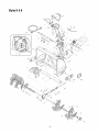
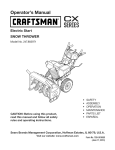
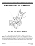
StylesH & K
ForRemoteChute
69 ......
7
_J
_
z32 30
ForManualChute
1
11
39
14
22
6
8
4
6
35b
7
64
J
53 5
56_
49
©
54
61
24
....35a
StylesH & K
REE
NO.
1
2
3
4
5
6
7
8
9
10
11
12
13
14
15
16
17
18
19
20
21
22
23
24
25
26
PART
NO.
731-2643
684-04057
710-0347
710-0451
710-0703
710-0726
712-04063
712-04064
712-04065
714-0507
725-0157
726-04012
731-04705
732-0611
736-0174
736-0463
731-04869
738-0143
738-0281
738-04124
741-0245
741-0309
756-0981A
790-00075
790-00080
631-04131
27
28
741-0475
710-0451t
710-0262tt
29 710-04071
30 720-0284t
31 710-0895tt
32 736-0159
33 784-5647
34 746-0897
35a 784-5580
35b 790-000915
36 629-0071
37 731-04426At
731-04427Att
38 731-1313C
39 731-2635
REF.
PART
NO.
NO.
40 784-5594tt
41 741-0663
42 618-04171
618-04173
618-04165
43 684-04069
684-04073
684-04063
44 684-04107 A
45 684-04108 A
46 731-04870*
731-04871"*
47 736-0188
48 736-3084
49 721-0179
50 741-0493A
51 790-00120
790-00118
790-00119
52 790-00087
53 618-0123
DESCRIPTION
Clean Out Tool
Impeller Assembly, 12" Dia
Screw, 3/8-16 x 1.75, Gr5, Std
Bolt, Carriage, 5/16-18 x.750 Grl
Screw, Carriage, 1/4-20 x.75, Gr5
Screw, 5/16-12 x 0.750
Nut, Flange Lock, Nylon, 5/16-18, GrF
Nut, Flange Lock, Nylon, 1/4-20, GrF
Nut, Flange Lock, Nylon, 3/8-16, GrF
Pin, Cotter, 3/32 x.750
Cable, Tie, 3/16 x.05 x 7.4
Nut, Push-on,.25 Dia
Chute, Adapter 5" Dia
Spring, Extension,.38 OD x 3.6
Washer, Wave,.625 x.885 x.015
Washer, Flat,.25 x.630 x.0515
Keeper, Flange
Screw, Shoulder,.498 x.340, 3/8-16
Screw, Shoulder,.625 x.17, 3/8-16
Pin, Shear,.25 x1.50, Gr2
Bearing, Hex Flange x.75 ID
Bearing, Ball,.75 ID x 1.85 OD
Pulley, Idler, Flat 2.75 OD
Housing, Bearing, 1.85 ID
Bracket, Auger Idler w/Brake
Chute Assembly, Lower, 2-way
(Inc. Ref 17, Qty. 3)
Plastic Bushing
Bolt, Carriage, 5/16-18,.750, Grl
Bolt, Carriage, 5/16-18, 1.50, Gr2
Bolt, Carriage, 5/16-18, 1.00
Knob Assembly
Screw, 1/4-15 x 0.75
Flat Washer,.349 x.879 x.063
Chute Directional Control Bracket
Auger Clutch Cable, 44.75"
Shoe, Slide, Standard
Shoe, Slide, Deluxe
Extension Cord, 3-Prong
Upper Chute, Manual
Upper Chute, Remote
Cable Guide, Chute Tilt
Mount, Clean Out Tool
54
618-0124
55
56
57
58
59
60
61
741-0661A
717-0528A
736-0351
714-0161
715-04021
721-0325
711-04285
711-04283
711-04282
710-0642
741-0662
717-04126
718-04071
721-0327
710-0276
746-0901
746-0896
736-0242
62
63
64
65
66
67
68
69
70
DESCRIPTION
Cable Bracket (Cables not included)
Bearing, Flange,.75 ID x 1.00 OD x.925
Gearbox Assembly, Auger, 24"
Gearbox Assembly, Auger, 28"
Gearbox Assembly, Auger, 30"
Housing Assembly, Auger 24"
Housing Assembly, Auger 28"
Housing Assembly, Auger 30"
Spiral Assembly, LH
Spiral Assembly, RH
Spacer, 1.25 OD x.75 ID x 1.00
Spacer, 1.25 OD x.75 ID x 3/16
Washer, Flat,.76 x 1.49 x.06
Washer, Flat,.51 x 1.12
Seal, Oil,.750 ID
Bushing, Flange,.800 ID x.910 OD
Plate, Shave, 24"
Plate, Shave, 28"
Plate, Shave, 30"
Housing, Bearing, 1" Hex
Housing Assembly, Auger, RH Reducer
(Inc. Refs. 49 & 55)
Housing Assembly, Auger, LH Reducer
(Inc. Refs. 49 & 55)
Bearing, Flange,.75 ID x 1.00 OD x.975
Gear, Worm 20T
Washer, Flat,.760 ID x 1.50D
Key, Hi-pro 3/16 x 5/8
Pin, Dowel,.25 OD x 1.2
Plug, 1/4 x.437
Axle, Auger, 24"
Axle, Auger, 28"
Axle, Auger, 30"
Screw, Self-tapping, 1/4-20, 0.750
Bearing, Flange,.75 ID x 1.00 OD x.59
Shaft, Worm.75 OD
Collar, Thrust
Seal, Oil,.75 x 1 x.131
Carriage Screw, 5/16-18 x 1.00
Chute Deflector Cable w/Clip
Chute Deflector Control Cable
Bell Washer
* One found between spirals on models with 24-inch auger housing.
* Three found between spirals on models with 28-inch auger housing.
** One found between spirals on models with 30-inch auger housing.
AThree found on models with 30-inch auger housing.
t H-Style
tt K-Style
$ If Equipped
NOTE:
Snow thrower features and components
are standard equipment.
vary by model. NOT all parts listed above and pictured on the previous page
25
StylesH & K
58
55
41
\
5O
17
67
68
58
53
57
4O
47
52
49
45
51
48
43
56
21
13
s
24
29
18
12
27
14"
36
24
14
4_
10
33
19
22
26
32
9
38
26
31
28"
37
25
StylesH & K
REE
NO.
1
2
3
4
5
6
7
8
9
10
11
12
13
14
15
16
17
18
19
20
21
22
23
24
25
26
27
28
29
30
31
32
33
34
PART
NO.
617-04026
617-04025
656-0012A
684-04066
684-04045
684-04139
710-0627
710-0788
710-1652
711-04246A
712-0711
714-0161
716-0231
716-0136
717-04129A
717-04137A
790-00082
726-0221
732-0264
736-0242
736-04161
736-0300
736-0105
736-0287
See Cha_
731-04873
738-04095A
738-0924
741-0563
741-0245
746-0897
746-04086
748-0190
756-0625
Wheel Assembly
Complete
DESCRIPTION
Gear Assembly, 16/44T
Gear Assembly, 16/44T
Disc Assembly, Friction Wheel,.375
Wheel Assembly, Friction, 4.90D
Support Bracket Ass'y, Friction Wheel
Shift Assembly, Rod
Screw, 5/16-24 x.750, Gr5
Screw, 1/4-20 x 1.000
Screw, 1/4-20 x.625
Hex Shaft, Drive,.75
Nut, Jam, 3/8-24, Gr2
Key, Hi-pro 3/16 x 5/8
Ring, E Type,.750
Ring, E-Type,.875
Pinion, 16T
Gear, 44T
Idler, Bracket, Drive
Nut, Speed,.500
Extension Spring
Washer, Bell,.340 x.872 x.060
Washer, Flat,.75 x 1.00 x.060
Washer, Flat,.406 x.875 x.059
Washer, Be11,.375x.870 x.063
Washer, Flat,.793 x 1.24 x.060
Wheel, Complete
Spacer, 1.25 OD x.75 ID x 3.00
Axle,.75 x 22
Screw, 1/4-28 x.375
Bearing, Ball, 17 x 40 x 12
Bearing, Hex Flange x.75 ID
Cable, Auger, 44.75
Cable, Drive, 41.75
Spacer,.508 ID x.75 OD x.68
Roller, Cable
Wheel Size
REE
PART
NO.
NO.
35 784-5687A
36 790-00072
37 790-00096
38 790-00054
39 790-00055
40 710-0191
41 710-0597
42 710-0654A
43 710-1245B
44 712-04064
45 731-04792
46 732-0710
47 736-0247
48 736-0505
49 741-0919
50 748-0234
51 748-04053
52 750-04230
53 750-04303
54 754-04050
55 754-0456
56 756-04109
57 756-04113
58 756-04114
59 790-00062
60 618-04169
61 718-04070
62 735-0243B
63 790-00010
64 790-00011
65 710-0896
66 723-0608
67 732-0705t
68 710-0602t
tlfEquipped
DESCRIPTION
Guide Bracket, Auger Cable
Frame
Guide Bracket, Front, Auger Cable
Cover, Frame
Roller Bracket, Drive Cable
Screw, 3/8-24 x 1.25, Gr8
Screw, 1/4-20 x 1.00, Gr5
Screw, Sems, 3/8-16 x 1.00
Screw, 5/16-24 x.875, Gr8
Nut, Flange Lock, Nylon, 1/4-20, GrF
Cover, Belt
Spring, Extension,.38 OD x 2.68
Washer, Flat,.406 x 1.25 x.157
Washer, Flat,.34 x 1.50 x.150
Bearing, Ball, 20 x 47 x 14
Shoulder Spacer
Pulley, Adapter,.75 Dia.
Spacer,.777 OD x.260 ID x.550
Spacer,.875 ID x 1.185 OD
V-Belt, 1/2"
V-Belt, 3/8"
Pulley, Auger, 8.1 x.50
Pulley, Half, 2.600 OD
Pulley, Half, 2.20D
Washer, Bearing, 2.12 OD x.255 ID
Bearing Assembly, Friction Wheel
Hub, Friction Wheel
Friction Wheel Rubber, 4.875 OD
Plate, Friction, 12 Pt 4.60 Dia
Plate, Friction, Extrs, 12 Pt 4.60 Dia
Screw, Self-tapping, 1/4-14 x 0.625
Tire Chain Set (Not Shown)
Chute Cable Guide
Screw, 5/16-18 x 1.00
Rim Only
Tire Only
Air Valve
634-04144
13x4
634-04151
734-1732
734-0255
634-04142
15x5
634-04151
734-1859
734-0255
634-04141
16x4.8
634-04140
734-1530
734-0255
NOTE:
Snow thrower features and components
are standard equipment.
vary by model. NOT all parts listed above and pictured on the previous page
27
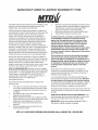
MANUFACTURER'S
LIMITED WARRANTY
The limited warranty set forth below is given by MTD LLC with
respect to new merchandise purchased and used in the
United States, its possessions and territories.
"MTD"warrants this product against defects in material and
workmanship for a period of two (2) years commencing on the
date of original purchase and will, at its option, repair or
replace, free of charge, any part found to be defective in
materials or workmanship. This limited warranty shall only
apply if this product has been operated and maintained in
accordance with the Operator's Manual furnished with the
product, and has not been subject to misuse, abuse,
commercial use, neglect, accident, improper maintenance,
alteration, vandalism, theft, fire, water, or damage because of
other peril or natural disaster. Damage resulting from the
installation or use of any part, accessory or attachment not
approved by MTD for use with the product(s) covered by this
manual will void your warranty as to any resulting damage.
Normal wear parts are warranted to be free from defects in
material and workmanship for a period of thirty (30) days from
the date of purchase. Normal wear parts include, but are not
limited to items such as: batteries, belts, blades, blade
adapters, grass bags, rider deck wheels, seats, snow thrower
skid shoes, shave plates, auger spiral rubber and tires.
HOW TO OBTAIN SERVICE: Warranty service is available,
WITH PROOF OF PURCHASE, through your local authorized
service dealer. To locate the dealer in your area, check your
Yellow Pages, or contact MTD LLC at P.O. Box 361131,
Cleveland, Ohio 44136-0019, or call 1-800-800-7310 or 1330-220-4683 or log on to our Web site at
www.mtdproducts.com.
This limited warranty does not provide coverage in the
following cases:
a.
b.
c.
d.
The engine or component parts thereof. These items
may carry a separate manufacturer's warranty. Refer
to applicable manufacturer's warranty for terms and
conditions.
Log splitter pumps, valves, and cylinders have a
separate one year warranty.
Routine maintenance items such as lubricants, filters,
blade sharpening, tune-ups, brake adjustments, clutch
adjustments, deck adjustments, and normal
deterioration of the exterior finish due to use or
e,
f,
g.
FOR:
MTD does not extend any warranty for products sold or
exported outside of the United States, its possessions
and territories, except those sold through MTD's
authorized channels of export distribution.
Replacement parts that are not genuine MTD parts.
Transportation charges and service calls.
No implied warranty, including any implied warranty of
merchantability of fitness for a particular purpose,
applies after the applicable period of express written
warranty above as to the parts as identified. No other
express warranty, whether written or oral, except as
mentioned above, given by any person or entity,
including a dealer or retailer, with respect to any product,
shall bind MTD. During the period of the warranty, the
exclusive remedy is repair or replacement of the product
as set forth above.
The provisions as set forth in this warranty provide the
sole and exclusive remedy arising from the sale. MTD
shall not be liable for incidental or consequential loss or
damage including, without limitation, expenses incurred
for substitute or replacement lawn care services or for
rental expenses to temporarily replace a warranted
product.
Some states do not allow the exclusion or limitation of
incidental or consequential damages, or limitations on how
long an implied warranty lasts, so the above exclusions or
limitations may not apply to you.
In no event shall recovery of any kind be greater than the
amount of the purchase price of the product sold. Alteration
of safety features of the product shall void this warranty.
You assume the risk and liability for loss, damage, or injury to
you and your property and/or to others and their property
arising out of the misuse or inability to use the product.
This limited warranty shall not extend to anyone other than the
original purchaser or to the person for whom it was purchased
as a gift.
HOW STATE LAW RELATES TO THIS WARRANTY: This
limited warranty gives you specific legal rights, and you may
also have other rights which vary from state to state.
IMPORTANT:Owner must present Original Proof of
Purchase to obtain warranty coverage.
exposure.
Service completed by someone other than an
authorized service dealer.
MTD LLC, P.O.BOX361131CLEVELAND,OHIO44136-0019; Phone:1-800-800-7310,1-330-220-4683