1
6RA70 Series Base Drive Instruction Manual, Rev. 7.0
6RA70 Series Base Drive Instruction Manual
Microprocessor-based converters from 15A -1680A
for variable speed DC drives
Rev 7.0
dc drives
0
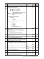
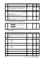
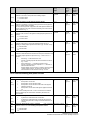
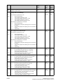
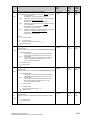
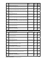
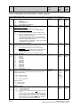
Contents
Page
1
Safety information
2
Introduction
3
1-1
2.1 Base Drive Panel Description
2-1
2.2 General Information
2-1
2.3 Rated DC Current
2-2
2.4 Card Rack Assembly
2-2
Parts and Service
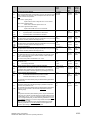
3.1 Base Drive Panel model numbers
3-1
3.2 Service
3-2
3.3 Option part numbers
3-3
3.4 Spare Parts
3-4
3.5 Standard Terms & Conditions
3-10
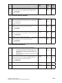
4
Receiving and Unpacking
4-1
5
Technical Data
6
7
5.1 15 to 100 ADC Base Drive Panels
5-1
5.2 140 to 850 ADC Base Drive Panels
5-2
5.3 1180 to 1680 ADC Base Drive Panels
5-3
5.4 Applicable Standards
5-5
Installation and Dimensions
6.1 Installation Information
6-1
6.2 Base Drive Panel Outlines
6-2
Base Drive Panel Connections
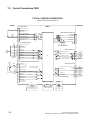
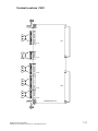
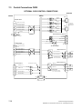
7.1 Base Drive Panel Schematics
7-2
7.2 Control Connections CUD1
7-16
7.3 Control Connections CUD2
7-18
7.4 Description of Power/Control Terminals
7-20
Siemens Energy & Automation
SIMOREG DC Master Base Drive Panel Operating Instructions
0-1
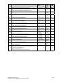
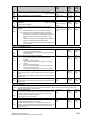
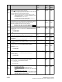
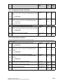
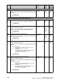
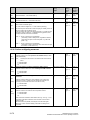
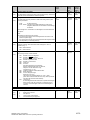
8
9
10
0-2
Start-up
8.1 General safety information
8-1
8.2 Operator control panels
8-2
8.3 Parameterization procedure
8-4
8.4 Typical connection diagrams
8-6
8.5 Reset to factory default values
8-8
8.6 Start-up procedure
8-9
Faults and Alarms
9.1 Fault messages
9-1
9.2 Alarm messages
9-28
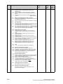
Abbreviated Parameter List
Overview
10-1
Overview of Abbreviations
10-3
10.1 Operating Status Display
10-5
10.2 General Visualization Parameters
10-7
10.3 Access Authorization Levels
10-11
10.4 Definition of SIMOREG Converter
10-13
10.5 Setting Values for Converter Control
10-17
10.6 Definition of Motor
10-22
10.7 Definition of Speed Sensing Pulse Encoder
10-27
10.8 Armature Current Control, Reversing, Gating
10-30
10.9 Current/Torque Limitation
10-32
10.10 Auto-reserving stage. Armature gating unit
10-34
10.11 Speed Controller
10-34
10.12 Field Current Control, Gating
10-36
10.13 Closed Loop EMF Control
10-38
10.14 Ramp Function Generator
10-39
10.15 Setpoint Processing
10-41
10.16 Ramp Function generator
10-42
10.17 Monitoring Functions and Limits
10-42
10.18 Limit-Value Monitors
10-43
10.19 Settable fixed values
10-45
10.20 Fixed control bits
10-46
10.21 Digital Setpoint Inputs
10-46
10.22 Position sensing with pulse encoder
10-48
10.23 Connector selector switches
10-49
Siemens Energy & Automation
SIMOREG DC Master Base Drive Panel Operating Instructions
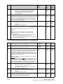
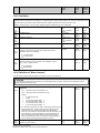
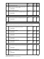
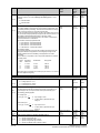
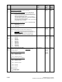
11
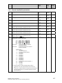
10.24 Motorized potentiometer
10-49
10.25 Oscillation
10-51
10.26 definition
Definition of
of Motor
Motor Interface
Inferface
10-52
10.27 Torque Shell Input
10-53
10.28 Speed limiting controller
10-54
10.29 Friction compensation
10-54
10.30 Compensation of moment of inertia(dv/dt injection)
10-55
10.31 Speed controller
10-57
10.32 Field reversal
10-59
10.33 Input Quantities for Signals
10-59
10.34 Configuring of Closed-Loop Control
10-60
10.35 Control and Status Word
10-68
10.36 Further Configuring Measures
10-71
10.37 Analog Inputs
10-72
10.38 Analog Outputs
10-76
10.39 Binary Outputs
10-78
10.40 Configuration of Serial Interfaces
10-79
10.41 Deactivation of Monitoring Functions
10-89
10.42 Compensation values
10-89
10.43 Thyristor Diagnostics
10-90
10.44 Parameters for DriveMonitor and OP1S
10-90
10.45 Profile Parameters
10-90
10.46 Fault memory
10-91
10.47 Visualization parameters: Alarms
10-92
10.48 Device identification
10-93
10.49 Visualization parameters: Control and status word
10-93
10.50 Resetting and Storing Parameters
10-93
Simplified Block Diagrams
11-1
Siemens Energy & Automation
SIMOREG DC Master Base Drive Panel Operating Instructions
0-3
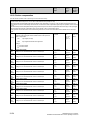
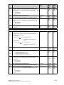
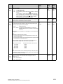
1
Safety information
WARNING
Hazardous voltages and rotating parts are present in this electrical equipment during
operation. Non-observance of the safety instructions can result in death, severe
personal injury or substantial property damage.
Only qualified personnel should work on or around the equipment after first becoming
thoroughly familiar with all warning and safety notices and maintenance procedures contained
herein. The successful and safe operation of this equipment is dependent on proper handling,
installation, operation and maintenance.
Definitions:
x QUALIFIED PERSONNEL
For the purpose of this Instruction Manual and product labels, a "Qualified Person" is someone who
is familiar with the installation, construction and operation of the equipment and the hazards
involved. He or she must have the following qualifications:
1. Trained and authorized to energize, de-energize, clear, ground and tag circuits and equipment in
accordance with established safety procedures.
2. Trained in the proper care and use of protective equipment in accordance with established
safety procedures.
3. Trained in providing first aid.
x DANGER
For the purpose of this Instruction Manual and product labels, "Danger" indicates that death,
severe personal injury or substantial property damage will result if proper precautions are not
taken.
x WARNING
For the purpose of this Instruction Manual and product labels, "Warning" indicates that death,
severe personal injury or substantial property damage can result if proper precautions are not
taken.
x CAUTION
For the purpose of this Instruction Manual and product labels, "Caution" indicates that minor
personal injury or property damage can result if proper precautions are not taken.
x NOTE
For the purpose of this Instruction Manual, "Note" indicates information about the product or the
respective part of the Instruction Manual which requires particular attention.
Siemens Energy & Automation
SIMOREG DC Master Base Drive Panel Operating Instructions
1-1
NOTE
These operating instructions do not purport to cover all details or variations in equipment, nor to
provide for every possible contingency to be met in connection with installation, operation or
maintenance.
Should further information be desired or should particular problems arise which are not covered
sufficiently for the purchaser's purposes, the matter should be referred to the local Siemens
Sales Office.
The contents of these operating instructions shall not become part or modify any prior or existing
agreement, commitment or relationship. The Sales Contract contains the entire obligations of
Siemens. The warranty contained in the contract between the parties is the sole warranty of
Siemens. Any statements contained herein do not create new warranties or modify the existing
warranty.
DANGER
Converters contain hazardous electrical voltages, Death, severe bodily injury or significant
material damage can occur if the safety measures are not followed.
1. Only qualified personnel, who are knowledgeable about the converters and the provided
information, can install, start up, operate, troubleshoot or repair the converters.
2. The converters must be installed in accordance with all relevant safety regulations (e.g.
NEC, DIN, VDE) as well as all other national or local regulations. Operational safety and
reliability must be ensured by correct grounding, cable sizing and appropriate short-circuit
protection.
3. All panels and doors must be kept closed during normal operation.
4. Before carrying out visual checks and maintenance work, ensure that the AC power supply
is disconnected and locked out. Before the AC supply is disconnected, both converters and
motors have hazardous voltage levels. Even when the converter contactor is open,
hazardous voltages are still present.
5. When making measurements with the power supply switched on, electrical connections
must not be touched under any circumstances. Remove all jewelry from wrists and fingers.
Ensure that the test equipment is in good conditions and operationally safe.
6. When working on units that are switched on, stand on an insulating surface, i.e. ensure that
you are not grounded.
7. Carefully follow the relevant instructions and observe all danger, warning and cautionary
instructions.
8. This does not represent a full listing of all the measures necessary for safe operation of the
equipment. If you require other information or if certain problems occur which are not
handled in enough detail in the information provided in the Instruction Manual, please
contact your local Siemens office.
1-2
Siemens Energy & Automation
SIMOREG DC Master Base Drive Panel Operating Instructions
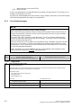
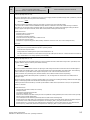
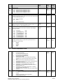
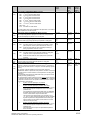
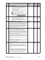
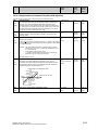
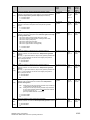
CAUTION
Electro-statically sensitive devices
The converter contains electro-statically sensitive devices. These can easily be destroyed if they are not
handled correctly. If, however, it is absolutely essential for you to work on electronic modules, please pay
careful attention to the following instructions:
x Electronic modules (PCBs) should not be touched unless work has to be carried out on them.
x Before touching a PCB, the person carrying out the work must himself be electro-statically discharged.
The simplest way of doing this is to touch an electrically conductive ground object, e.g. socket outlet
ground contact.
x PCBs must not be allowed to come into contact with electrically insulating materials plastic foil,
insulating table tops or clothing made of synthetic fibers x PCBs may only be set down or stored on electrically conducting surfaces.
x When carrying out soldering jobs on PCBs, make sure that the soldering tip has been grounded.
x PCBs and electronic components should generally be packed in electrically conducting containers
(such as metallized-plastic boxes or metal cans) before being stored or shipped.
x If the use of non-conducting packing containers cannot be avoided, PCBs must be wrapped in a
conducting material before being put in them. Examples of such materials include electrically
conducting foam rubber or household aluminum foil.
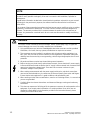
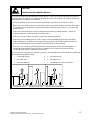
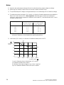
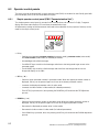
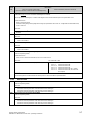
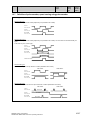
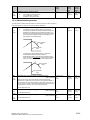
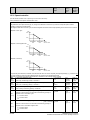
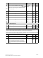
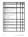
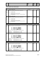
For easy reference, the protective measures necessary when dealing with sensitive electronic components
are illustrated in the sketches below.
a
=
Conductive flooring
d
=
Anti-static overall
b
=
Anti-static table
e
=
Anti-static chain
c
=
Anti-static footwear
f
=
Grounding connections of cabinets
d
d
b
e
e
f
a
Seated workstation
d
b
f
f
c
a
Standing workstation
Siemens Energy & Automation
SIMOREG DC Master Base Drive Panel Operating Instructions
f
f
c
a
Standing/seated workstation
1-3
NOTES:
1-4
Siemens Energy & Automation
SIMOREG DC Master Base Drive Panel Operating Instructions
2
Description
2.1
Base Drive Panel Description
Series 6RA70 SIMOREG DC MASTER Base Drive Panels are complete drive assemblies ready to be
installed and operated. They include a 3-phase armature converter, single-phase field converter, main
contactor, protective semiconductor fuses, control power transformer, and power / control terminals.
Base Drive Panels are fully digital, compact units which supply the armature and field of variablespeed DC drives with rated armature currents from 15A to 1680A. The motor field circuit can be
supplied with DC currents of up to 85A (current levels depend on the armature rated current).
2.2
General Information
Series 6RA70 SIMOREG DC MASTER converters are characterized by their compact, space-saving
construction. Their compact design makes them particularly easy to service and maintain since
individual components are readily accessible. The electronics box contains the basic electronic
circuitry as well as any supplementary option boards.
All SIMOREG DC MASTER units are equipped with a PMU simple operator panel mounted in the
converter door. The panel consists of a five-digit, seven-segment display, three LED’s as status
indicators and three parameterization keys. The PMU also features connector X300 with an USS
interface in accordance with the RS232 or RS485 standard. The panel provides all the facilities for
making adjustments or settings and displaying measured values required to start-up the converter.
The OP1S optional converter operator panel can be mounted directly in the converter door or
externally, e.g., in the cubicle door. When mounted remotely, the OP1S can be connected to the
converter with cables up to 5 meters (15 feet) length. Cable up to 50 meter (164 feet) in length can be
used if a separate 5 VDC power supply is available. The OP1S connects to the SIMOREG through
connector X300 using the RS485 interface. The OP1S can be installed as an economic alternative to
conventional door mounted metering devices (i.e., voltmeters, ammeters, and speed indicator).
The OP1S features a liquid crystal display with 4 x 16 characters for displaying parameter names in
plain text. English, German, French, Spanish and Italian can be selected as the display languages. In
addition the OP1S can store parameter sets for easy downloading to other drives.
The converter can also be parameterized on a standard PC with appropriate software connected to the
serial interface on the basic unit. This PC interface is used during start-up, for maintenance during
shutdown and for diagnosis in operation. Furthermore, converter software upgrades can be loaded
through this interface for storage in flash memory.
On single-quadrant converters, a fully controlled three-phase bridge supplies the armature. On fourquadrant converters, two fully controlled three-phase bridges are connected in an inverse-parallel
connection to allow both positive and negative armature current. For the field converter, a singlephase, half-controlled 2-pulse bridge supplies the motor shunt field.
The armature and field converters can operate with AC line frequencies from 45 to 65 Hz. If required
for a specific application, the frequency of the armature and field AC supplies can be different. The
armature converter 3 phase AC supply is phase insensitive however on base drives rated 1180, 1660
and 1680 amperes, the 3 phase cooling fan must be connected to get the proper direction of rotation.
The power section cooling system is monitored by means of temperature sensors.
Siemens Energy & Automation
SIMOREG DC Master Base Drive Panel Operating Instructions
2-1
The power section for the armature and field converters is constructed of isolated thyristor modules for
converters rated from 15A to 850A at 460VAC-line voltage. The heat sink in this case is electrically
isolated and at ground potential. On converters rated 1180, 1660 and 1680 amperes at 460 VAC, the
power section for the armature circuit is constructed using disk thyristors and the heat sinks are at line
voltage potential. The housing and terminal covers on power connections provide protection against
accidental contact for operators working in the vicinity. All connecting terminals are accessible from the
front.
All open and closed-loop drive control and communication functions are performed by two powerful
microprocessors. Drive control functions are implemented in the software as program modules that can
be "wired up" and changed by parameters.
2.3
Rated DC Current:
The rating plate of the 6RA70 power module has 2 rated currents listed on it. The first output rating is a
IEC class I ratings and has no bearing on the base drive panel rating. The second rating is the US
(NEMA) rating which the Base Drive Panel rating is derived from.
The US (NEMA) rated current allows operation at this rated current followed by an overload of 150%
for 60 seconds in a 45qC ambient. The overload can be applied no sooner than every 10 minutes.
Base Drive Panels are designed using the US rating which means that fuses, contactors, and terminal
blocks are sized for the rated US (NEMA) current.
The IEC class I rating is the maximum current the power module can supply continuously with no
overload. Because an overload is not possible the class I rated current is higher than the US rating.
The IEC class I rating cannot be used with Base Drive Panels because the Base Drive Panel fuses,
contactors, and terminal blocks will be overloaded.
The microprocessor calculates the current I2t value of the power section cyclically to ensure that the
thyristors are not damaged in overload operation.
2.4
Card Rack Assembly
One of the many features of the 6RA70 is its ability to expand its functionality modularly through the
use of adding additional option cards inserted in the internal card rack of the power module. A
complete list of the option cards can be found in 6RA70 catalog available from your local Siemens
Sales office.
The card rack assembly contains the CUD1 microprocessor board and two additional slots for two full
size option cards or four half-size option cards. The back plane of the card rack assembly contains an
EEPROM allowing the CUD1 to be replaced without reprogramming of the parameters. Since
additional information specific to the individual unit is programmed into the back plane of the
card rack assembly (model #, serial #, PIN code, etc..) the card rack assembly should never be
interchanged with another unit. If ordering an additional back plane (part # 6RY1703-0GA01)
the model and serial number of the power module will be required.
2-2
Siemens Energy & Automation
SIMOREG DC Master Base Drive Panel Operating Instructions
3
Parts and Service
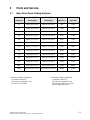
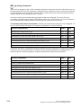
3.1
Base Drive Panel Catalog Numbers
US RATING
1-QUAD TYPE
4-QUAD TYPE
Horsepower
1
Horsepower
(Amps DC)
(Catalog No.)
(Catalog No.)
(240V DC )
(500V DC)
15
6RA7013-2FS22-0
6RA7013-2FV62-0
3HP
7.5HP
30
6RA7018-2FS22-0
6RA7018-2FV62-0
7.5HP
15HP
60
6RA7025-2FS22-0
6RA7025-2FV62-0
15HP
30HP
100
6RA7030-2FS22-0
6RA7030-2FV62-0
25HP
60HP
140
6RA7072-2FS22-0
6RA7072-2FV62-0
40HP
75HP
210
6RA7075-2FS22-0
6RA7075-2FV62-0
60HP
125HP
255
6RA7077-2FS22-0
6RA7077-2FV62-0
75HP
150HP
430
6RA7082-2FS22-0
6RA7082-2FV62-0
125HP
250HP
510
6RA7083-2FS22-0
6RA7083-2FV62-0
150HP
300HP
850
6RA7087-2FS22-0
6RA7087-2FV62-0
250HP
500HP
1180(2)
6RA7091-2FS22-0
6RA7091-2FV62-0
350HP
700HP
1660(2)
6RA7094-2FS22-0
6RA7094-2FV62-0
500HP
1000HP
1680(2)
6RA7094-2FS22-085
6RA7094-2FV62-085
500HP
1000HP
1) Standard voltage configuration
as shipped is 460V AC.
See Technical application note
for 230V AC connection.
Siemens Energy & Automation
SIMOREG DC Master Base Drive Panel Operating Instructions
2) Standard voltage configuration
as shipped is 460V AC.
See Technical application note
for 575V AC connection on 1180
1660 & 1680A Base drives
3-1
3.2
Service
Spare Parts
An excellent stock of drive products spare parts is maintained at the Alpharetta, Georgia factory. Same
day delivery and after hour shipments can be serviced from this stock, including on weekends and
holidays. To contact Customer Service, simply call our Customer Service Group general phone number:
1-800-333-PIC1 (7421)
Technical Assistance
Should you need technical assistance (other than ordering a part), a reliable answering service ensures
that your request is relayed immediately to one of our technical support engineers 24 hours a day. To
contact the Technical Support and Field Service groups simply call:
1-800-333-PIC1 (7421)
3-2
Siemens Energy & Automation
SIMOREG DC Master Base Drive Panel Operating Instructions
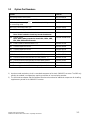
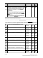
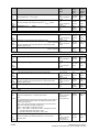
3.3
Option Part Numbers
Options
Order No.
Terminal expansion card (CUD2)
6RX1700-0AK00
User-friendly operator control panel (OP1S)
6SE7090-0XX84-2FK0
AOP1 adapter for mounting AOP1
OP1A in cubicle door, including
5 m connecting cable
6SX7010-0AA00
PMU-OP1S connecting cable, 3m
6SX7010-0AB03
PMU-OP1S connecting cable, 5m
6SX7010-0AB05
LBA
6SE7090-0XX84-4HA0
Local bus adapter for the electronics box
Note: LBA is needed to install any boards listed below
ADB Adapter board
Note: ADB is always needed to install CBC, CBP2, CBD,
EB1, EB2, SBP and SLB boards
SBP Pulse encoder evaluation board
6SE7090-0XX84-0KA0
1) 2)
6SX7010-0FA00
EB1
Terminal expansion board
2)
6SX7010-0KB00
EB2
Terminal expansion board
2)
6SX7010-0KC00
SLB
SIMOLINK board
2)
CBP2 Communications board interface for PROFIBUS
CBC Communications board interface for CAN protocol
6SX7010-0FJ00
2)
6SX7010-0FF05
2)
6SX7010-0FG00
CBD Communications board interface for DeviceNet protocol
2)
6SX7010-0FK00
T400 Technology board with SPW 420 Axial winder software
2)
6DD1-842-0AA0
T400 Technology board with SPW 440 Angular Synchr. Software
2)
6DD1-842-0ABO
1) A pulse encoder evaluation circuit is a standard component of the basic SIMOREG converter. The SBP only
needs to be ordered in configurations requiring evaluation of a second pulse encoder.
2) The LBA local bus adapter and ADB adapter board must be ordered as additional components for installing
supplementary boards in the SIMOREG converter.
Siemens Energy & Automation
SIMOREG DC Master Base Drive Panel Operating Instructions
3-3
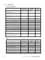
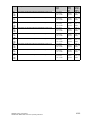
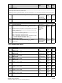
3.4
Spare Parts
Printed Circuit Boards
DESCRIPTION
Microprocessor board CUD1
WHERE USED
US Rating 460V
PART
NUMBER
RECOM
SPARE
All Ratings
01
6RY1703-0AA00
1
All 1Q Ratings
6RY1703-0DA01
1
All 4Q Ratings
6RY1703-0DA02
1
PMU Operator Panel (C98 043-A7005-L1)
All Ratings
6RY1704-0AA00
-
Field Supply board
(C98 043-A7014-L1)
30 to 100 Amp
6RY1703-0CA03
1
Field Supply board
(C98 043-A7014-L2)
140 to 510 Amp
6RY1703-0CA01
1
Field Supply board
(C98 043-A7004-L1)
850 to 1660 Amp
6RY1703-0EA01
1
Field Supply board
(C98 043-A7004-L3)
1680 Amp
6RY1703-0EA03
1
Snubber board
(C98 043-A7007-L4)
60 to 100 Amp
6RY1703-0FA04
Snubber board
(C98 043-A7007-L6)
30, 140 & 210 Amp
6RY1703-0FA11
-
Snubber board
(C98 043-A7011-L6)
255 & 430 Amp
6RY1703-0FA10
-
Snubber boards
(C98 043-A7011-L1) 510 & 850 Amp
6RY1703-0FA06
-
15 Amp (1Q, 4Q)
6RY1703-0CA04
1
15 – 1680 Amp
6RY1702-0BA00
2
(C98 043-A7001-L1)
L2)
Power Interface board 1Q (85 to 575 VAC)
(C98 043-A7002-L1)
Power Interface board 4Q (85 to 575 VAC)
(C98 043-A7002-L4)
Main Power Section Connector board
(C98 043-A7010-L2)
Fuse for Power Supply, 1 amp F1, F2
Mounted on Power Interface board
Cables
DESCRIPTION
3-4
WHERE USED
US Rating 460V
PART
NUMBER
RECOM
SPARE
Ribbon Cable 20 pole X102
15 amp
6RY1707-0AA00
Ribbon Cable 64 pole X101
15 to 430 amp
6RY1707-0AA01
-
Ribbon Cable 20 pole X102
30 to 210 amp
6RY1707-0AA02
-
Ribbon Cable 20 pole X102
255 & 430 amp
6RY1707-0AA03
-
Ribbon Cable 20 pole X102
510 amp
6RY1707-0AA12
-
Ribbon Cable 64 pole X101
510 amp
6RY1707-0AA05
-
Ribbon Cable 20 pole X102
850 to 1680 amp
6RY1707-0AA06
-
Ribbon Cable 64 pole X101
850 to 1680 amp
6RY1707-0AA07
-
Siemens Energy & Automation
SIMOREG DC Master Base Drive Panel Operating Instructions
Fans/Blowers
DESCRIPTION
FAN, 24 VDC
WHERE USED
US Rating 460V
PART NUMBER
RECOM
SPARE
140 & 210 amp
6RY1701-0AA07
2
255, 430 & 510
amp
6RY1701-0AA11
1
850 amp
6RY1701-0AA12
1
1180, 1660
&1680 amp
6RY1701-0AA04
1
(C98130-A1256-C553)
FAN, 230 VAC, 1 Phase
(C98130-A7004-B130)
FAN, 230 VAC, 1 Phase
(C98130-A7004-B330)
FAN, 460 VAC, 3 Phase
(C98 247-S1002-C25)
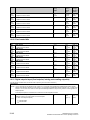
Thyristors & Diodes
Armature Converter Thyristor Modules, (for 1-Quad Drives)
DESCRIPTION
WHERE USED
US Rating 460V
PART NUMBER
RECOM
SPARE
Dual Thyristor Module
15 amp
1Q
6RY1700-0AA16
3
Dual Thyristor Module
30 amp
1Q
6RY1700-0AA17
3
Dual Thyristor Module
60 amp
1Q
6RY1700-0AA18
3
Dual Thyristor Module
100 amp
1Q
6RY1700-0AA11
3
Dual Thyristor Module
140 amp
1Q
6RY1700-0AA14
3
Dual Thyristor Module
210 amp
1Q
6SY7010-0AA02
3
Dual Thyristor Module
255 amp
1Q
6RY1700-0AA15
3
Dual Thyristor Module
430 amp
1Q
6SY7010-0AA05
3
Dual Thyristor Module
510 amp
1Q
6SY7010-0AA04
3
Dual Thyristor Module
850 amp
1Q
6RY1700-0AA04
3
Thyristor/Heatsink Assembly, Front
1180 amp
1Q
6RY1702-0CA15
2
1180 amp
1Q
6RY1702-0CA16
2
1660 amp
1Q
6RY1702-0CA17
2
1660 amp
1Q
6RY1702-0CA18
2
Thyristor/Heatsink Assembly, Front
1680 amp
1Q
6RY1702-0CA30
2
Thyristor/Heatsink Assembly, Back
1680 amp
1Q
6RY1702-0CA31
2
(C98 130-A1255-B510)
Thyristor/Heatsink Assembly, Back
(C98 130-A1255-B511)
Thyristor/Heatsink Assembly, Front
(C98 130-A1255-B520)
Thyristor/Heatsink Assembly, Back
(C98 130-A1255-B521)
Siemens Energy & Automation
SIMOREG DC Master Base Drive Panel Operating Instructions
3-5
Armature Converter Thyristor Modules, (for 4-Quad Drives)
DESCRIPTION
WHERE USED
US Rating 460V
PART NUMBER
RECOM
SPARE
Dual Thyristor Module
15 amp
4Q
6RY1700-0AA16
3
Dual Thyristor Module
30 amp
4Q
6RY1700-0AA17
3
Dual Thyristor Module
60 & 100 amp
4Q
6RY1700-0AA11
3
Dual Thyristor Module
140 amp
4Q
6RY1700-0AA14
3
Dual Thyristor Module
210 amp
4Q
6SY7010-0AA02
3
Dual Thyristor Module
255 amp
4Q
6RY1700-0AA15
3
Dual Thyristor Module
430 amp
4Q
6SY7010-0AA05
3
Dual Thyristor Module
510 to 850 amp 4Q
6SY7010-0AA04
3
Thyristor/Heatsink Assembly
1180 amp
4Q
6RY1702-0CA02
2
1660 amp
4Q
6RY1702-0CA03
2
1680 amp
4Q
6RY1702-0CA34
2
C98 130-A1256-B510
Thyristor/Heatsink Assembly
C98 130-A1256-B520
Thyristor/Heatsink Assembly
Field Converter Thyristor Modules
DESCRIPTION
WHERE USED
US Rating 460V
PART NUMBER
RECOM
SPARE
Dual Thyristor Module
15 to 430 amp
6RY1700-0AA12
1
Dual Thyristor Module
510 to 1660 amp
6RY1700-0AA17
1
Dual Thyristor Module
1680 amp
6RY1700-0AA05
1
PART NUMBER
RECOM
Field Converter Diode Modules
DESCRIPTION
3-6
WHERE USED
US Rating 460V
SPARE
Dual Diode Module
15 to 430 amp
6RY1700-0BA04
1
Dual Diode Module
510 to 1660 amp
6RY1700-0BA01
1
Dual Diode Module
1680 AMP
6RY1700-0BA05
1
Siemens Energy & Automation
SIMOREG DC Master Base Drive Panel Operating Instructions
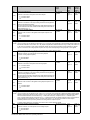
Power Fuses
Armature Converter AC Line Fuses, (1PFU - 3 PFU)
DESCRIPTION
WHERE USED
US Rating 460V
PART NUMBER
RECOM
25 amp, 700 volt
15 amp
A1-FUF-END-C25
3
50 amp, 700 volt
30 amp
A1-FUF-END-CDN
3
70 amp, 500 volt
60 amp
A1-FUF-00D-014
3
125 amp, 500 volt
100 amp
A1-FUF-00D-018
3
150 amp, 500 volt
140 amp
A1-FUF-00D-019
3
200 amp, 500 volt
210 amp
A1-FUF-00D-021
3
250 amp, 500 volt
255 amp
A1-FUF-00D-023
3
400 amp, 500 volt
430 amp
A1-FUF-00D-028
3
500 amp, 500 volt
510 amp
A1-FUF-00D-030
3
800 amp, 800 volt (Leg Fuse)
850 amp
3NE3338-8
3
1000 amp, 660 volt (Leg Fuse)
1180 amp
6RY1702-0BA02
3
1250 amp, 660 volt (Leg Fuse)
1660 amp
6RY1702-0BA01
3
1500 amp, 660 volt (Leg Fuse)
1680 amp
6RY1702-0BA05
3
SPARE
Armature Converter DC Fuses, 4-Quad Only, (4PFU)
DESCRIPTION
WHERE USED
US Rating 460V
PART NUMBER
25 amp, 700 volt
15 amp
A1-FUF-END-C25
2
50 amp, 700 volt
30 amp
A1-FUF-END-CDN
2
90 amp, 700 volt
60 amp
A1-FUF-00E-016
2
150 amp, 700 volt
100 amp
A1-FUF-00E-019
2
175 amp, 700 volt
140 amp
A1-FUF-00E-020
2
250 amp, 700 volt
210 amp
A1-FUF-00E-023
2
300 amp, 700 volt
255 amp
A1-FUF-00E-025
2
500 amp, 700 volt
430 amp
A1-FUF-00E-030
2
600 amp, 700 volt
510 amp
A1-FUF-00E-031
2
Siemens Energy & Automation
SIMOREG DC Master Base Drive Panel Operating Instructions
RECOM
SPARE
3-7
Field Converter AC Line Fuses (1 & 2FSFU)
DESCRIPTION
WHERE USED
US Rating 460V
PART NUMBER
RECOM
SPARE
20 amp, 700 volt
60 to 210 amp
A1-FUF-END-C20
2
40 amp, 700 volt
255 to 850 amp
A1-FUF-END-C40
2
50 amp, 700 volt
1180 to 1660 amp A1-FUF-END-C50
2
125 amp, 600 volt
1680 amp
A1-FUF-HHA-024
2
PART NUMBER
RECOM
Control Transformer Primary Fuses (1CFU, 2CFU)
DESCRIPTION
WHERE USED
US Rating 460V
SPARE
1.25 amp, 600 volt, Class "CC"
15 to 100 amp
A1-FUF-AFA-006
2
2.5 amp, 600 volt, Class "CC"
140 & 210 amp
A1-FUF-AFA-011
2
A1-FUF-AFA-014
2
A1-FUF-AFA-016
4
PART NUMBER
RECOM
1180, 1660 &
1680 amp
3.5 amp, 600 volt, Class "CC"
255 to 510 amp
850 amp, (460
volt input only)
5 amp, 600 volt, Class "CC"
1180, 1660 &
1680 amp
(4CFU, 5CFU,
6CFU, 7CFU)
Control Transformer Secondary Fuse (3CFU)
DESCRIPTION
WHERE USED
US Rating 460V
SPARE
0.75 amp, 250 volt, Type MDL
15 to 100 amp
A1-FUF-DKA-GBF
2
1.5 amp, 250 volt, Type MDL
140 & 210 amp
A1-FUF-DKA-GBP
2
1180,1660 &
1680 amp
3-8
2 amp, 250 volt, Type MDL
255 to 510 amp
A1-FUF-DKA-GBV
2
6.25 amp, 250 volt, Type MDL
850 amp
A1-FUF-DKA-GCM
2
Siemens Energy & Automation
SIMOREG DC Master Base Drive Panel Operating Instructions
Control Transformer (1CTR, 2CTR, 3CTR)
DESCRIPTION
460 VAC Primary
WHERE USED
US Rating 460V
PART NUMBER
RECOM
SPARE
115 VA, 230 VAC secondary
15 to 100 amp
A1-TRC-Q0C-285
-
250 VA, 230 VAC secondary
140 & 210 amp
A1-TRC-Q0C-286
-
1180, 1660 &
1680 amp
350 VA, 230 VAC secondary
255 to 510 amp
A1-TRC-Q0C-287
-
1000 VA, 230 VAC secondary
850 amp
A1-TRC-Q0C-288
-
750 VA, 460 VAC secondary
1180,1660 &
1680 amp
A1-TRC-Q0C-289
-
Main Contactor (M)
DESCRIPTION
WHERE USED
US Rating 460V
PART NUMBER
RECOM
SPARE
3 Pole AC contactor, 240 VAC coil
15 amp
3RT1016-1AP61
-
3 Pole AC contactor, 240 VAC coil
30 amp
3RT1025-1AP60
-
3 Pole AC contactor, 240 VAC coil
60 amp
3RT1035-1AP60
-
3 Pole AC contactor, 240 VAC coil
100 amp
3RT1044-1AP60
-
3 Pole AC contactor, 240 VAC coil
140 amp
3RT1045-1AP60
-
3 Pole AC contactor, 240 VAC coil
210 amp
3RT1456-6AP36
-
3 Pole AC contactor, 240 VAC coil
255 amp
3RT1456-6AP36
-
1 Pole DC contactor, 250 VDC coil
430 to 1680 amp
A1-CRD-CAC-010
-
Contactor Coil Suppressor (1SP, ENSP)
DESCRIPTION
Suppressor, varistor type 127 – 240 V
WHERE USED
US Rating 460V
15 amp
PART NUMBER
RECOM
SPARE
3RT1916-1BD00
-
3RT1926-1BD00
-
WHERE USED
US Rating 460V
PART NUMBER
RECOM
Relay, 2-NO, 2-NC, 230 VAC coil
430 to 1680 amp
3RH1122-1AP60
-
Rectifier Bridge, 1 Phase, 5A, 800 V
430 to 1680 amp
A1-116-002-001
-
430 to 1680 amp
Suppressor, varistor type 127 – 240 V
30 to 140 amp
Auxiliary Relay, (EN), and Rectifier Bridge, (MREC)
DESCRIPTION
Siemens Energy & Automation
SIMOREG DC Master Base Drive Panel Operating Instructions
SPARE
3-9
3.5
Standard Terms and Conditions of Sale
Siemens Energy & Automation, Inc. ("Seller")
1.
WARRANTY - Seller warrants that on the date of shipment the goods are of the kind and quality described herein and are free of nonconformities in workmanship and material. This warranty does not apply to goods delivered by Seller but manufactured by others.
(b) Buyer's exclusive remedy for a nonconformity in any item of the goods shall be the repair or the replacement (at Seller's option) of
the item and any affected part of the goods. Seller's obligation to repair or replace shall be in effect for a period of one (1) year from
initial operation of the goods but not more than eighteen (18) months from Seller's shipment of the goods, provided Buyer has sent
written notice within that period of time to Seller that the goods do not conform to the above warranty. Repaired and replacement parts
shall be warranted for the remainder of the original period of notification set forth above, but in no event less than 12 months from repair
or replacement. At its expense, Buyer shall remove and ship to Seller any such nonconforming items and shall reinstall the repaired or
replaced parts. Buyer shall grant Seller access to the goods at all reasonable times in order for Seller to determine any nonconformity in
the goods. Seller shall have the right of disposal of items replaced by it. If Seller is unable or unwilling to repair or replace, or if repair or
replacement does not remedy the nonconformity, Seller and Buyer shall negotiate an equitable adjustment in the contract price, which
may include a full refund of the contract price for the nonconforming goods.
(c) SELLER HEREBY DISCLAIMS ALL OTHER WARRANTIES, EXPRESS OR IMPLIED, EXCEPT THAT OF TITLE. SPECIFICALLY,
IT DISCLAIMS THE IMPLIED WARRANTIES OF MERCHANTABILITY, FITNESS FOR A PARTICULAR PURPOSE, COURSE OF
DEALING AND USAGE OF TRADE.
(d) Buyer and successors of Buyer are limited to the remedies specified in this article and shall have no others for a nonconformity in
the goods. Buyer agrees that these remedies provide Buyer and its successors with a minimum adequate remedy and are their
exclusive remedies, whether Buyer's or its successors' remedies are based on contract, warranty, tort (including negligence), strict
liability, indemnity, or any other legal theory, and whether arising out of warranties, representations, instructions, installations, or nonconformities from any cause.
Note: This article 1 does not apply to any software which may be furnished by Company. In such cases, the attached Software License
Addendum applies.
2. PATENTS - Seller shall pay costs and damages finally awarded in any suit against Buyer or its vendees to the extent based upon a
finding that the design or construction of the goods as furnished infringes a United States patent (except infringement occurring as a
result of incorporating a design or modification at Buyer's request), provided that Buyer promptly notifies Seller of any charge of
infringement, and Seller is given the right at its expense to settle such charge and to defend or control the defense of any suit based
upon such charge. Seller shall have no obligation hereunder with respect to claims, suits or proceedings, resulting from or related to, in
whole or in part, (i) the use of software or software documentation, (ii) compliance with Buyer's specifications, (iii) the combination with,
or modification of, the goods after delivery by Seller, or (iv) the use of the goods, or any part thereof, in the practice of a process. THIS
ARTICLE SETS FORTH SELLER'S ENTIRE LIABILITY WITH RESPECT TO PATENTS.
3. PERFORMANCE; DELAYS - TTimely performance by Seller is contingent upon Buyer's supplying to Seller, when needed, all
required technical information and data, including drawing approvals, and all required commercial documentation. If Seller suffers delay
in performance due to any cause beyond its reasonable control, the time of performance shall be extended a period of time equal to the
period of the delay and its consequences. Seller will give to Buyer notice within a reasonable time after Seller becomes aware of any
such delay.
4. SHIPMENT, TITLE AND RISK OF LOSS - (a) The term "shipment" means delivery to the initial carrier in accordance with the delivery
terms of this contract. Seller may make partial shipments. Seller shall select method of transportation and route, unless terms are f.o.b
point of shipment and Buyer specifies the method and route and is to pay the freight costs in addition to the price. When terms are f.o.b.
destination or freight allowed to destination, "destination" means common carrier delivery point (within the United States, excluding
Alaska and Hawaii) nearest the destination.
(b) Title to the goods and risk of loss or damage shall pass to Buyer at the f.o.b. point. Seller shall not be responsible for damage to the
goods after having received "in good order" receipts from the carrier.
5. TAXES - Any applicable duties or sales, use, excise, value-added or similar taxes will be added to the price and invoiced separately
(unless an acceptable exemption certificate is furnished).
6. TERMS OF PAYMENT - (a) Unless otherwise stated, all payments shall be in United States dollars, and a pro rata payment shall
become due as each shipment is made. If shipment is delayed by Buyer, date of notice of readiness for shipment shall be deemed to be
date of shipment for payment purposes.
(b) On late payments, the contract price shall, without prejudice to Seller's right to immediate payment, be increased by 1 1/2% per
month on the unpaid balance, but not to exceed the maximum permitted by law.
(c) If any time in Seller's judgment Buyer is unable or unwilling to meet the terms specified, Seller may require satisfactory assurance or
full or partial payment as a condition to commencing or continuing manufacture or making shipment, and may, if shipment has been
made, recover the goods from the carrier, pending receipt of such assurances.
3-10
Siemens Energy & Automation
SIMOREG DC Master Base Drive Panel Operating Instructions
7. NONCANCELLATION - Buyer may not cancel or terminate for convenience, or direct suspension of manufacture, except with Seller's
written consent and then only upon terms that will compensate Seller for its engineering, fabrication and purchasing charges and any other
costs relating to such cancellation, termination or suspension,
uspension, plus a reasonable amount for profit.
8. NUCLEAR - Buyer represents and warrants that the goods covered by this contract shall not be used in or in connection with a nuclear
facility or application. If Buyer is unable to make such representation and warranty, then Buyer agrees to indemnify and hold harmless Seller
and to waive and require its insurers to waive all right of recovery against Seller for any damage, loss, destruction, injury or death resulting
from a "nuclear incident", as that term is defined in the Atomic Energy Act of 1954, as amended, whether or not due to Seller's negligence.
9. LIMITATION OF LIABILITY - Neither Seller, nor its suppliers shall be liable, whether in contract, warranty, failure of a remedy to achieve
its intended or essential purposes, tort (including negligence), strict liability, indemnity or any other legal theory, for loss of use, revenue or
profit, or for costs of capital or of substitute use or performance, or for indirect, special, liquidated, incidental or consequential damages, or for
any other loss or cost of a similar type, or for claims by Buyer for damages of Buyer's customers. Seller's maximum liability under this
contract shall be the contract price. Buyer and Seller agree that the exclusions and limitations set forth in this article are separate and
independent from any remedies which Buyer may have hereunder and shall be given full force and effect whether or not any or all such
remedies shall be deemed to have failed of their essential purpose.
10. GOVERNING LAW AND ASSIGNMENT - The laws of the State of Georgia shall govern the validity, interpretation and enforcement of
this contract, without regard to its conflicts of law principles. The application of the United Nations Convention on Contracts for the
International Sale of Goods shall be excluded. Assignment may be made only with written consent of both parties; provided, however, Seller
may assign to its affiliate without Buyer's consent.
11. ATTORNEY FEES - Buyer shall be liable to Seller for any attorney fees and costs incurred by Seller in enforcing any of its rights
hereunder.
12. DISPUTES - Either party may give the other party written notice of any dispute arising out of or relating to this contract and not resolved
in the normal course of business. The parties shall attempt in good faith to resolve such dispute promptly by negotiations between executives
who have authority to settle the dispute. If the matter has not been resolved within 60 days of the notice, either party may initiate non-binding
mediation of the dispute.
13. STATUTE OF LIMITATIONS - To the extent permitted by applicable law, any lawsuit for breach of contract, including breach of warranty,
arising out of the transactions covered by this contract, must be commenced not later than twelve (12) months from the date the cause of
action accrued.
14. PRICES - In the event of a price increase or decrease, the price of goods on order will be adjusted to reflect such increase or decrease.
This does not apply to a shipment held by request of Buyer. Goods already shipped are not subject to price increase or decrease. Orders on
a bid or contract basis are not subject to this article. Orders amounting to less than $100.00 net will be invoiced at $100.00 plus
transportation charges for goods covered by discount schedules. Seller's prices include the costs of standard domestic packing only. Any
deviation from this standard packing (domestic or export), including U.S. Government sealed packing, will result in extra charges. To
determine such extra charges, consult Seller's sales offices.
15. ADDITIONAL TERMS OF PAYMENT - (a) Invoice payment terms are as shown on latest discount sheets as issued from time to time.
Cash discounts are not applicable to notes or trade acceptances, to prepaid transportation charges when added to Seller's invoices or to
discountable items if there are undisputed past due items on the account. Portions of an invoice in dispute should be deducted and the
balance remitted with a detailed explanation of the deduction. Cash discounts will only be allowed on that portion of the invoice paid within
the normal discount period.
(b) Freight will be allowed to any common-carrier free-delivery point within the United States, excluding Alaska and Hawaii, on shipments
exceeding $1,000 net or more providing Seller selects the carrier. On shipments to Alaska and Hawaii, freight will be allowed to dockside at
the listed port of debarkation nearest the destination point on shipments of $1,000 net or more. Buyer shall pay all special costs such as
cartage, stevedoring and insurance. Special freight allowances are as shown on latest discount sheets as issued from time to time.
Cataloged weights are estimated, not guaranteed. Seller assumes no responsibility for tariff classifications on carriers.
16. CHANGES IN LAWS AND REGULATIONS - Seller's prices and timely performance are based on all applicable laws, rules, regulations,
orders, codes, standards or requirements of governmental authorities effective on the date of Seller's proposal. Any change to any law, rule,
regulation, order, code, standard or requirement which requires any change hereunder shall entitle Seller to an equitable adjustment in the
prices and any time of performance.
Siemens Energy & Automation
SIMOREG DC Master Base Drive Panel Operating Instructions
3-11
NOTES:
3-12
Siemens Energy & Automation
SIMOREG DC Master Base Drive Panel Operating Instructions
4
Receiving, unpacking
SIMOREG Base Drive Panels are packed at the manufacturing plant in protective containers suitable
for shipping. Avoid dropping and shocks during unloading and moving the SIMOREG during receiving.
Observe the instructions on the package for transport, storage, and correct handling.
If you discover that the Base Drive Panel has been damaged during shipment, please inform your
shipping agent immediately.
WARNING
If a SIMOREG Base Drive Panel was damaged during transport, it must not be connected up
without first being repaired and tested by a qualified repair person.
Non-observance of the safety instructions can result in death, severe personal injury or
substantial property damage.
Only qualified personnel should work on or around the equipment after first becoming
thoroughly familiar with all warning and safety notices and maintenance procedures contained
herein. The successful and safe operation of this equipment is dependent on proper handling,
installation, operation and maintenance.
Procedure for Shipping Damage
SIMOREG Base Drive Panels are normally shipped FOB factory making it the buyers responsibility to
make sure the equipment is received undamaged. Carefully examine the equipment before accepting
the shipment from the transport carrier. If you do not notify the carrier immediately of any damage you
may lose your right to file a damage claim. If required you can request support from the local Siemens
office.
x
x
When received, examine the shipment to ensure that it is complete and not damaged.
x
Immediately notify the transport company in writing of any damage or missing items
Damaged or missing items that are obviously visible should be specified in the shipping papers
and must be countersigned by personnel from the transport company.
Siemens Energy & Automation
SIMOREG DC Master Base Drive Panel Operating Instructions
4-1
NOTES:
4-2
Siemens Energy & Automation
SIMOREG DC Master Base Drive Panel Operating Instructions
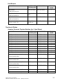
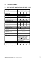
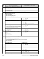
5
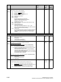
Technical data:
5.1 15ADC to 100ADC Base Drive Panels, 3AC 460V, 1 & 4Q
V
Rated supply voltage
armature
3 Phase
460 (+10% / – 5%)
1)
A
Rated input current
armature + field
17.3
34.6
59.2
92
2)
Rated supply voltage field
V
Rated frequency
Hz 45 to 65 Hz self adapting (armature
and field are independent)
Rated DC voltage
V
3)
Rated DC armature current
Overload capability 60s
1 Phase 460 (+10%)
A
500
15
30
60
100
150% of rated DC current
7)
Rated output @ 500 VDC
Hp
7½
15
30
60
Rated output @ 240 VDC
Hp
3
7½
15
25
Power loss at rated DC current
(approximate)
W
150
200
360
510
Rated DC voltage field
V
Rated DC field current
A
Operational ambient
temperature
°C
0 to 45 at Irated
self-cooled 4)
Storage and transport
temperature
°C
– 25 to +70
300
5
10
d 1000 m at rated DC current
Installation altitude above sea
5)
level
'n = 0.006% of the rated motor
speed, valid for pulse encoder
operation and digital setpoint
'n = 0.1% of the rated motor
speed, valid for analog tachometer
or analog setpoint 6)
Control stability
Degree of protection
Open Chassis (IP00)
Dimensions
See dimension drawings in Section 6
Weights (approx.)
x) Explanation
Lbs.
50
35
55
50
70
60
75
70
at end of list of tables
Siemens Energy & Automation
SIMOREG DC Master Base Drive Panel Operating Instructions
5-1
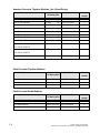
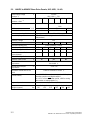
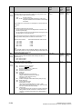
5.2 140ADC to 850ADC Base Drive Panels, 3AC 460V, 1 & 4Q
V
Rated supply voltage
armature
3 Phase
460 (+10% / – 5%)
1)
Rated input current
armature + field
A
129.8
187.2
V
Internal 24VDC
234.1
377.6
448.2
727
2)
Fan type
1 Phase
230V
Air flow rate
3/h
3/min
ftm
Fan noise level
dBA
100
570
1300
40
76
85
Rated supply voltage field
V
Rated frequency
Hz 45 to 65 Hz self adapting (armature and field are
independent)
Rated DC voltage
V
3)
Rated DC armature current
Overload capability 60s
1 Phase 460 (+10%)
A
500
140
210
255
430
510
850
150% of rated DC current
7)
Rated output @ 500 VDC
Hp
75
125
150
250
300
500
Rated output @ 240 VDC
Hp
40
60
75
125
150
250
Power loss at rated DC current
(approximately)
W
740
1000
1300
1915
2180
3850
Rated DC voltage field
V
Rated DC field current
A
Operational ambient
temperature
°C
0 to 45 at Irated
fan-cooled 4)
Storage and transport
temperature
°C
– 25 to +70
300
15
25
d 1000 m at rated DC current
Installation altitude above sea
30
5)
level
'n = 0.006% of the rated motor speed, valid for pulse
encoder operation and digital setpoint
'n = 0.1% of the rated motor speed, valid for analog
tachometer or analog setpoint 6)
Control stability
Degree of protection
Open Chassis (IP00)
Dimensions
Weights (approx.)
5-2
Lbs.
Refer to dimension drawings in Section 6
125
210
225
125
225
90
95
145
160
210
400
625
Siemens Energy & Automation
SIMOREG DC Master Base Drive Panel Operating Instructions
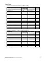
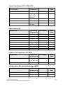
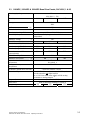
5.3 1180ADC, 1660ADC & 1680ADC Base Drive Panels, 3AC 460V, 1 & 4Q
Rated supply voltage armature
1)
V
3 Phase
460 (+10% / – 5%)
Rated input current armature
A
Fan type
V
2)
1000
1401
1455
3 Phase
460V
Air flow rate
824
3/h
3/min
ftm
Fan noise level
dBA
88
Rated supply voltage field
V
1 Phase 460 (+10%)
Rated frequency
Hz 45 to 65 Hz self adapting (armature and field are
independent)
Rated DC voltage
V
2)
Rated DC armature current
Overload capability 60s
A
500
1180
1660
1680
150% of rated DC current
7)
Rated output @ 500 VDC
Hp
700
1000
1000
Rated output @ 240 VDC
Hp
350
500
500
Power loss at rated DC current
(approximately)
W
5540
7590
7280
Rated DC voltage field
V
Rated DC field current
A
Operational ambient
temperature
°C
0 to 45 at Irated
fan-cooled 4)
Storage and transport
temperature
°C
– 25 to +70
300
40
d 1000 m at rated DC current
Installation altitude above sea level
5)
'n = 0.006% of the rated motor speed, valid for pulse
encoder operation and digital setpoint
'n = 0.1% of the rated motor speed, valid for analog
tachometer or analog setpoint 6)
Control stability
Degree of protection
Open Chassis (IP00)
Dimensions
Weights (approx.)
85
Refer to dimension drawings in Section 6
Lbs.
725
900
Siemens Energy & Automation
SIMOREG DC Master Base Drive Panel Operating Instructions
755
1050
760
1050
5-3
Notes:
1) Operation with reduced input voltage will result in reduced maximum output voltage accordingly.
2) Values apply for rated DC output current on both the armature and field circuits.
3) The specified output DC voltage can be guaranteed up to an undervoltage of 5% of rated line voltage.
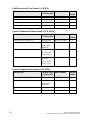
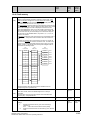
4) The table below gives load values, (DC current), as a function of ambient temperature surrounding the
Base Drive Panel, (refer to P077). Note, Important: When Base Drive Panels are installed into
enclosures, make sure the temperature inside does not exceed 45oC, otherwise derate the DC current
rating per the table below.
Ambient temperature
% reduction in base drive dc ampere rating
Self-cooled converters
Fan-cooled converters
(15, 30, 60, 100 ADC)
a)
(140 - 1660 ADC)
+40ºC
–0 %
–0 %
+45ºC
–0 %
–0 %
+50ºC
–6 %
–5 %
a)
+55ºC
– 11 %
–5 %
a)
+60ºC
– 18 %
–5 %
a)
Operation of fan cooled units at ambients above 50oC is not permitted
because of limitations on the allowable fan operating temperature.
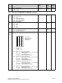
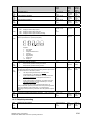
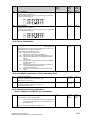
5) Load values, (DC current), as a function of installation altitude (refer to P077)
Percentage
load "b"
b1
%
100
80
67%
60
40
20
0
1000
2000
3000
4000
5000 m
Installation altitude
Curve b1: Reduction factor of load values, (DC current),
at installation altitudes above 1000 m.
No derating of the supply voltages to any circuits is required
up to an installation altitude of 5000 m for basic insulation.
5-4
Siemens Energy & Automation
SIMOREG DC Master Base Drive Panel Operating Instructions
6)
Requirements to achieve control stability:
The control stability (closed-loop PI control) is referred to the rated motor speed and applies
when the SIMOREG converter is warm. The following conditions are applicable:
x
x
x
x
x
7)
Temperature changes of ±10 °C.
Line voltage changes corresponding to +10% / – 5% of the rated input voltage.
Temperature coefficient of temperature-compensated tachometer 0.15‰ per 10 °K,
(applies only to analog tachometer).
Constant setpoint (14-bit resolution).
Motor, load, and encoder are correctly aligned and the load is balanced.
Details of overload capability:
Following operation at rated load, base drive panels are capable of carrying 150% of rated load
for 1 minute, followed by a period of light load operation of such duration that the rms load does
not exceed rated continuous current. Base Drive Panels are designed for operation with
heatsink air inlet temperatures up to 45°C.
5.4
Applicable standards
UL508A
National Electrical Code 1999
Siemens Energy & Automation
SIMOREG DC Master Base Drive Panel Operating Instructions
5-5
NOTES:
5-6
Siemens Energy & Automation
SIMOREG DC Master Base Drive Panel Operating Instructions
6
Installation and Dimensions
6.1
Installation Information
SIMOREG Base Drive Panels are designed as chassis units intended to be mounted inside a protective
enclosure or inside a control room. The units are to be mounted vertically in cubicles usually with the power
connections at the top and the control connections at the bottom. A minimum 100-mm (4-inch) clearance must
be kept above and below the converter in order to ensure unrestricted cooling airflow. The minimum
enclosure size to be used is 23.6 by 23.6 by 86.6 inch high. The open chassis units are designed to operate in
a 45°C ambient. When enclosed in a cubicle the ambient temperature outside the cubicle should not exceed
40°C, which then allows for a 5°C-temperature rise inside the cubicle. Care must be taken in the selection of
the cubicle so that the internal temperature rise does not exceed 5°C. Refer to section 5 for approximate
power loss data.
Note, Important: This equipment is designed and package-protected to handle the normal shock and
vibration typically encountered in shipment. Do not install these Base Drive Panels on equipment subject
to shock or vibration. Select a reasonably clean location for installation, free from corrosive or
conductive materials or fumes.
CAUTION
Failure to lift the Base Drive Panel in the correct manner can result in bodily injury and/or
property damage.
The Base Drive Panel must be lifted using suitable equipment and under the instruction of
appropriately qualified personnel.
The user is responsible for installing the Base Drive Panel, motor, transformer as well as other
equipment according to safety regulations (e.g. NEC), as well as all other relevant national or
local regulations regarding cable sizing and protection, grounding, disconnects, overcurrent
protection, etc.
The Base Drive Panels must be installed in accordance with the relevant safety regulations
(e.g. NEC), as well as all other relevant national and local regulations. It must be ensured that
the grounding, cable sizing and appropriate short-circuit protection have been implemented to
guarantee operational safety and reliability.
Note, Important: Base Drive Panels have high-speed semiconductor fuses installed for
protection of the thyristors in the event high fault currents are encountered. These fuses are
“special purpose” fuses, and do not meet the requirements of the NEC for short-circuit
protection in motor branch circuits. It is necessary to provide other devices for short-circuit
protection. Typically molded case circuit breakers or NEC style fuses are used for this purpose.
Refer to applicable sections of the NEC for additional information.
NOTE
The fundamental principles of EMC in Section 6.1 of SIMOREG 6RA70 DC Master operating
instructions (Order # 6RX1700-0AD76) must be adhered to when installing any unit.
Siemens Energy & Automation
SIMOREG DC Master Base Drive Panel Operating Instructions
6-1
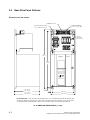
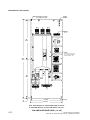
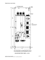
6.2
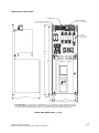
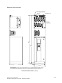
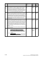
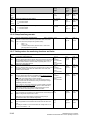
Base Drive Panel Outlines:
Dimensions are mm (inches)
TERMINALS 80 - 92
POWER TERMINALS
L1, L2, L3, A1, A2, GND
MOUNTING HOLES FOR M8,
(.312"), SCREWS, 4-PLACES
FUSE NOT
SUPPLIED ON
1-QUAD UNITS
638
(2 5 .1 )
SIEMENS
6RA70
613
(24.1)
P
(1 5 A m p )
2 6 5 (1 0 .4 )
(3 0 A m p )
3 3 9 ( 1 3 .4 )
9
(0 .4 )
15
(0 .6 )
X300
2 3 8 (9 .4 )
2 6 8 (1 0 .6 )
NOTE, IMPORTANT: ALLOW AT LEAST 100 MILLIMETERS, (4"), OF CLEARANCE ABOVE AND BELOW THE UNIT
TO ENSURE UNRESTRICTED AIR FLOW. ADDITIONAL CLEARANCE MAY BE REQUIRED TO ALLOW FOR WIRE
OR CABLE ENTRY/EXIT AND BENDING. REFER TO APPLICABLE CODES FOR FURTHER INFORMATION.
15 - 30 AMP BASE DRIVE PANELS, (1 & 4Q)
6-2
Siemens Energy & Automation
SIMOREG DC Master Base Drive Panel Operating Instructions
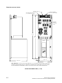
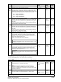
Dimensions are mm (inches)
TERMINALS 80 - 92
POWER TERMINALS
L1, L2, L3, A1, A2, GND
MOUNTING HOLES FOR M8,
(.312"), SCREWS, 4-PLACES
FUSE NOT
SUPPLIED ON
1-QUAD UNITS
734
(2 8 .9 )
709
(27.9)
SIEMENS
P
3 3 9 (1 3 .4 )
9
(0 .4 )
15
(0 .6 )
6RA70
X300
238 (9.4)
2 6 8 (1 0 .6 )
NOTE, IMPORTANT: ALLOW AT LEAST 100 MILLIMETERS, (4"), OF CLEARANCE ABOVE AND BELOW THE UNIT
TO ENSURE UNRESTRICTED AIR FLOW. ADDITIONAL CLEARANCE MAY BE REQUIRED TO ALLOW FOR WIRE
OR CABLE ENTRY/EXIT AND BENDING. REFER TO APPLICABLE CODES FOR FURTHER INFORMATION.
60 AMP BASE DRIVE PANEL, (1 & 4Q)
Siemens Energy & Automation
SIMOREG DC Master Base Drive Panel Operating Instructions
6-3
Dimensions are mm (inches)
TERMINALS 80 - 92
POWER TERMINALS
MOUNTING HOLES FOR M8,
(.312"), SCREWS, 4-PLACES
L1, L2 , L3, A1, A2, GND
FUSE NOT
SUPPLIED
ON 1-QUAD
UNITS
831
(32.7)
806
(31.7)
SIEMENS
P
3 3 9 (1 3 .4 )
15
(0 .6 )
6RA70
X300
2 3 8 (9 .4 )
2 6 8 (1 0 .6 )
NOTE, IMPORTANT: ALLOW AT LEAST 100 MILLIMETERS, (4"), OF CLEARANCE ABOVE AND BELOW THE UNIT
TO ENSURE UNRESTRICTED AIR FLOW. ADDITIONAL CLEARANCE MAY BE REQUIRED TO ALLOW FOR WIRE
OR CABLE ENTRY/EXIT AND BENDING. REFER TO APPLICABLE CODES FOR FURTHER INFORMATION.
100 AMP BASE DRIVE PANEL, (1 & 4Q)
6-4
Siemens Energy & Automation
SIMOREG DC Master Base Drive Panel Operating Instructions
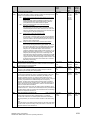
Dimensions are mm (inches)
MOUNTING HOLES FOR M8,
(.312"), SCREWS, 4-PLACES
GROUND
TERMINAL
L1
L2
L3
TERMINALS 80 - 92
A1
A2
FUSE NOT
SUPPLIED
ON 1-QUAD
UNITS
980
(38.6)
960
(37.8)
SIEMENS
P
326(12.8)
10
(0.4)
12
(0.45)
6RA70
X300
266(10.5)
290(11.4)
NOTE, IMPORTANT: ALLOW AT LEAST 100 MILLIMETERS, (4"), OF CLEARANCE ABOVE AND BELOW THE UNIT
TO ENSURE UNRESTRICTED AIR FLOW. ADDITIONAL CLEARANCE MAY BE REQUIRED TO ALLOW FOR WIRE
OR CABLE ENTRY/EXIT AND BENDING. REFER TO APPLICABLE CODES FOR FURTHER INFORMATION.
140 AMP BASE DRIVE PANEL, (1 & 4Q)
Siemens Energy & Automation
SIMOREG DC Master Base Drive Panel Operating Instructions
6-5
Dimensions are mm (inches)
MOUNTING HOLES FOR M8,
(.312"), SCREWS, 4-PLACES
TERMINALS 80 - 92
GROUND
TERMINAL
L1
L2
L3
A1
A2
FUSE NOT
SUPPLIED ON
1-QUAD UNITS
1120
(44.1)
1100
(43.3)
SIEMENS
P
326(12.8)
10
(0.4)
12
(0.45)
6RA70
X300
266 (10.5)
290 (11.4)
NOTE, IMPORTANT: ALLOW AT LEAST 100 MILLIMETERS, (4"), OF CLEARANCE ABOVE AND BELOW THE UNIT
TO ENSURE UNRESTRICTED AIR FLOW. ADDITIONAL CLEARANCE MAY BE REQUIRED TO ALLOW FOR WIRE
OR CABLE ENTRY/EXIT AND BENDING. REFER TO APPLICABLE CODES FOR FURTHER INFORMATION.
210 AMP BASE DRIVE PANEL, (1 & 4Q)
6-6
Siemens Energy & Automation
SIMOREG DC Master Base Drive Panel Operating Instructions
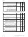
Dimensions are mm (inches)
MOUNTING HOLES FOR M8,
(.312"), SCREWS, 4-PLACES
GROUND
TERMINAL
L1
L2
TERMINALS 80 - 92
A1
L3
A2
FUSE NOT
SUPPLIED ON
1-QUAD UNITS
SIEMENS
6RA70
1180
(46.5)
1160
(45.7)
331 (13.0)
10
(0.4)
12
(0.45)
266 (10.5)
290 (11.4)
NOTE, IMPORTANT: ALLOW AT LEAST 100 MILLIMETERS, (4"), OF CLEARANCE ABOVE AND BELOW THE UNIT
TO ENSURE UNRESTRICTED AIR FLOW. ADDITIONAL CLEARANCE MAY BE REQUIRED TO ALLOW FOR WIRE
OR CABLE ENTRY/EXIT AND BENDING. REFER TO APPLICABLE CODES FOR FURTHER INFORMATION.
255 AMP BASE DRIVE PANEL, (1 & 4Q)
Siemens Energy & Automation
SIMOREG DC Master Base Drive Panel Operating Instructions
6-7
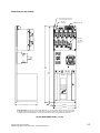
Dimensions are mm (inches)
MOUNTING HOLES FOR M10,
(.375"), SCREWS, 6-PLACES
L1
L2
L3
A1
GROUND TERMINAL
A2
FUSE NOT SUPPLIED
ON 1-QUAD UNITS
TERMINALS 80 - 94
280
(11.0)
ADDITIONAL CLEARANCE
REQ'D FROM CONTACTOR
ARC CHUTE TO ANY
GROUNDED METAL
35
(1.4)
SIEMENS
6RA70
1200
(47.2)
880
(34.6)
P
20
(0.8)
15
(0.6)
X300
334 (13.1)
520 (20.5)
550 (21.6)
348 (13.7)
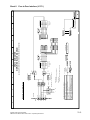
430 AMP BASE DRIVE PANEL, (1 & 4Q)
6-8
Siemens Energy & Automation
SIMOREG DC Master Base Drive Panel Operating Instructions
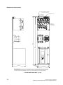
Dimensions are mm (inches)
MOUNTING HOLES FOR M10,
(.375"), SCREWS, 6-PLACES
L2
L1
L3
A1
GROUND TERMINAL
A2
FUSE NOT SUPPLIED
ON 1-QUAD UNITS
280
(11.0)
TERMINALS 80 - 94
ADDITIONAL CLEARANCE
REQ'D FROM CONTACTOR
ARC CHUTE TO ANY
GROUNDED METAL
35
(1.4)
1200
(47.2)
SIEMENS 6RA70
880
(34.6)
P
20
(0.8)
15
(0.6)
X300
520 (20.5)
550 (21.6)
348 (13.7)
376 (14.8)
NOTE, IMPORTANT: ALLOW AT LEAST 100 MILLIMETERS, (4"), OF CLEARANCE ABOVE AND BELOW THE UNIT
TO ENSURE UNRESTRICTED AIR FLOW. ADDITIONAL CLEARANCE MAY BE REQUIRED TO ALLOW FOR WIRE
OR CABLE ENTRY/EXIT AND BENDING. REFER TO APPLICABLE CODES FOR FURTHER INFORMATION.
510 AMP BASE DRIVE PANEL, (1 & 4Q)
Siemens Energy & Automation
SIMOREG DC Master Base Drive Panel Operating Instructions
6-9
Dimensions are mm (inches)
MOUNTING HOLES FOR M10,
(.375"), SCREWS, 6-PLACES
A1
A2
L1
GROUND
TERMINAL
L3
L2
TERMINALS
80 - 94
740
(29.1)
SIEMENS
6RA70
1524
(60.0)
P
X300
NOTE:
SEMICONDUCTOR
FUSES ARE
LOCATED INSIDE
THE 6RA70
POWER MODULE
740
(29.1)
CABLE CONNECTIONS
TO POWER MODULE
THIS AREA
425 (16.7)
22
(0.9)
22
(0.9)
768 (30.2)
813 (32.0)
850 AMP BASE DRIVE PANEL, (1 & 4Q)
6-10
Siemens Energy & Automation
SIMOREG DC Master Base Drive Panel Operating Instructions
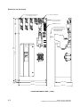
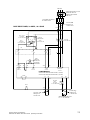
Dimensions are mm (inches)
MOUNTING SLOTS, FOR M12
(0.50"), SCREWS, 6-PLACES
L1
L2
GROUND
TERMINAL
L3
TERMINALS
80 - 102
CTB
L1-1
L2-1
80
81
82 83
84
85 90 91 92 93 94 95 96 97 98 99 100101102
80
81
82 83
84
85 90 91 92 93 94 95 96 97 98 99 100101102
L3-1
1
2FSFU
7CFU
6CFU
5CFU
4CFU
1
1FSFU
965
(38.0)
1
1
RATE D
600V,3 0A
N O T OP E N
U N D E R L OA D
N OT O P E N
U N D E R L OA D
2
1
RATE D
600V,30A
T M
D O
2
2
1
RATE D
600V,3 0A
TM
DO
RATE D
600V,30A
TM
D O
N OT O P E N
U N D E R L OA D
2
TM
DO
N OT OP E N
U NDE RL O A D
2
2
1CTR
PM
H1 H3 H2 H4
1CF U
L1
2.5 A, 60 0V
2CF U
L2
2.5 A, 60 0V
3CFU
1.5A, 250V
X2
XF X1
NOTE:
2CTR
P
H1
X300
H3
H2
H4
SEMICONDUCTOR FUSES
ARE LOCATED INSIDE THE
POWER MODULE, (PM).
1981
(78.0)
X2
X1
3CTR
H1
1C1
1D1
H3
H2
X2
MREC
X1
EN
MSPAUX
MSP
965
(38.0)
H4
M
A2
A1
25
(1.0)
767 (30.2)
23 (0.9)
813 (32.0)
NOTE: FROM THE BACK OF THE MOUNTING PANELTO THE TOP
OF THE POWER MODULE, (TALLEST COMPONENT) = 629 (24.8")
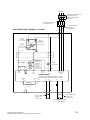
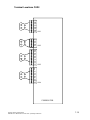
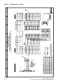
1180 AMP BASE DRIVE PANEL, (1 & 4Q)
Siemens Energy & Automation
SIMOREG DC Master Base Drive Panel Operating Instructions
6-11
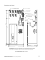
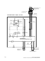
Dimensions are mm (inches)
MOUNTING SLOTS, FOR M12
(0.50"), SCREWS, 6-PLACES
L1
GROUND
TERMINAL
L3
L2
TERMINALS
80 - 102
L1-1
L2-1
80
81
82 83
84
85
90 91 92 93 94 95 96 97 98 99 100101102
80
81
82 83
84
85
90 91 92 93 94 95 96 97 98 99 100101102
L3-1
1
2FSFU
7CFU
6CFU
5CFU
4CFU
1
1FSFU
965
(38.0)
1
1
RATE D
600V, 30
A
TM
2
2
1
RATE D
600V, 30
A
T M
RATE D
600V, 30
A
1
TM
RATE D
600V, 30
A
T M
DO NOTOPE NUNDER LOAD DO NOTOPE NUNDER LOAD DO NOTOPE NUNDER LOAD DO NOTOPE NUNDER LOAD
2
2
2
2
1CTR
PM
H1 H3 H2 H4
1C FU
2. 5A, 6 00V
L1
2C FU
L2
2. 5A, 6 00V
3CFU
1.5A , 250 V
X2
XF X1
NOTE:
2CTR
P
X300
H1
H3
H2
H4
SEMICONDUCTOR FUSES
ARE LOCATED INSIDE THE
POWER MODULE, (PM).
1981
(78.0)
X2
X1
3CTR
H1
1C1
1D1
H3
H2
X2
MREC
EN
M1
M2
A1
25
(1.0)
X1
MSPAUX
MSP
965
(38.0)
H4
A2
767 (30.2)
23 (0.9)
813 (32.0)
NOTE: FROM THE BACK OF THE MOUNTING PANELTO THE TOP
OF THE POWER MODULE, (TALLEST COMPONENT) = 629 (24.8")
6-12
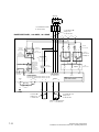
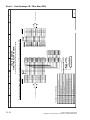
1660 AMP BASE DRIVE PANEL, (1 & 4Q)
Siemens Energy & Automation
SIMOREG DC Master Base Drive Panel Operating Instructions
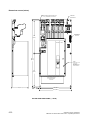
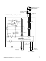
Dimensions are mm (inches)
MOUNTING SLOTS, FOR M12
(0.50"), SCREWS, 6-PLACES
L1
GROUND
TERMINAL
L3
L2
TERMINALS
80 - 102
L1-1
L2-1
L3-1
81
82 83
84
85
80
81
82 83
84
85
90 91 92 93 94 95 96 97 98 99 100 101102
90 91 92 93 94 95 96 97 98 99 100101102
1
2FSFU
7CFU
6CFU
5CFU
4CFU
1
1FSFU
965
(38.0)
80
1
1
RATE D
600V, 30
A
TM
2
2
1
RATE D
600V, 30
A
TM
RATE D
600V, 30
A
1
TM
RATE D
600V, 30
A
TM
DO NOTOPEN UNDER LOAD DO NOTOPEN UNDER LOAD DO NOTOPEN UNDER LOAD DO NOTOPEN UNDER LOAD
2
2
2
2
1CTR
PM
H1 H3 H2 H4
1C FU
2. 5A , 6 00V
L1
2C FU
L2
2. 5A , 6 00V
NOTE:
3CFU
1.5A, 250 V
X2
XF X1
SEMICONDUCTOR FUSES
ARE LOCATED INSIDE THE
POWER MODULE, (PM).
2CTR
P
X300
H1
H3
H2
H4
1981
(78.0)
X2
X1
3CTR
H1
1C1
1D1
H3
H2
X2
MREC
EN
M1
M2
A2
A1
25
(1.0)
X1
MSPAUX
MSP
965
(38.0)
H4
767 (30.2)
23 (0.9)
813 (32.0)
NOTE: FROM THE BACK OF THE MOUNTING PANELTO THE TOP
OF THE POWER MODULE, (TALLEST COMPONENT) = 629 (24.8")
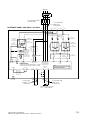
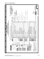
1680 AMP BASE DRIVE PANEL, (1 & 4Q)
Siemens Energy & Automation
SIMOREG DC Master Base Drive Panel Operating Instructions
6-13
NOTES:
6-14
Siemens Energy & Automation
SIMOREG DC Master Base Drive Panel Operating Instructions
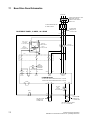
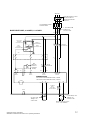
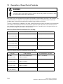
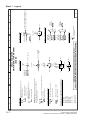
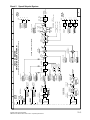
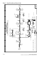
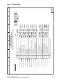
7 Base Drive Panel Connections
WARNING
Base Drive Panels are operated at high voltages.
Disconnect the power supply before making any connections!
Only qualified personnel who are thoroughly familiar with all safety notices contained in the
operating instructions as well as erection, installation, operating and maintenance instructions
should be allowed to work on these devices.
Non-observance of the safety instructions can result in death, severe personal injury or
substantial property damage.
Failure to make the correct connections may result in irreparable damage to the unit.
Voltage may be present at the power and control terminals even when the motor is stopped.
The snubber capacitors may still carry a hazardous voltage for up to 2 minutes after
disconnection. For this reason, wait for at least 2 minutes before opening the converter.
When working on the open converter, remember that live parts are exposed. The unit must
always be operated with the standard front covers in place.
The user is responsible for ensuring that the motor, SIMOREG Base Drive Panel and other
devices are installed and connected up in accordance with the approved codes of practice of
the country concerned and any other regional or local codes that may apply. Special attention
must be paid to proper conductor sizing, fusing, grounding, isolation and disconnection
measures and to overcurrent protection.
These units contain hazardous rotating machinery (fans) and control rotating mechanical
components (motors). Death, serious bodily injury or substantial property damage may occur if
the instructions in the relevant operating manuals are not observed.
The successful and safe operation of this equipment is dependent on careful transportation,
proper storage and installation as well as correct operation and maintenance.
Siemens Energy & Automation
SIMOREG DC Master Base Drive Panel Operating Instructions
7-1
7.1
Base Drive Panel Schematics
460 VAC
MAIN DISCONNECT AND
BRANCH CIRCUIT
PROTECTION SIZED
PER N.E.C.
CUSTOMER SUPPLIED
IF APPLICABLE
#4 AWG,60 C
TORQUE TO
11 INCH- LBS
L3
2PFU
3PFU
1CFU
H1
3CFU
0.75A,250V
A1-FUF-DKA-GBF
L2
L2
1CTR
H2
3CFU
XF
H3
2CFU
L1
1CFU - 2CFU
1.25A,600V
A1-FUF-AFA-006
L1
1PFU
BASE DRIVE PANEL, 15 AMPS, 1 & 4 QUAD
H4
CONTROL
TRANSFORMER
115VA
A1-TRC-Q0C-285
25A,700V
A1-FUF-END-C25
230 V
X2
CTB
88
86
J3
87
J2
89
M
1SP
XP
XR
XR
5U1 5W1
PWR
SUPPLY
109
110
XP
85
J4
K1
82
J1
84
83
M
MAIN
CONTACTOR
3RT1016-1AP61
SUPPRESSOR
3RT1916-1BD00
XP
XF1-2
5N1
PWR
SUPPLY
XF1-1
3U1 3W1
FIELD
SUPPLY
1U1 1V1 1W1
ARMATURE
SUPPLY
POWER MODULE
CATALOG NO. 6RA7018-6FS22-0Z+X01, (1-QUAD)
CATALOG NO. 6RA7018-6FV62-0Z+X01, (4-QUAD)
XS
E-STOP
105
3C
XS
3D
4Q UNITS
ONLY
25A,700V
A1-FUF-END-C25
MAUX
F(+)
90
80
91
#10 AWG, 60 C
TORQUE TO
5 INCH- LBS
7-2
1C1
1D1
XF2-1
XF2-2
4PFU
106
F(-)
81
A1
A2
#4 AWG,60 C
TORQUE TO
11 INCH- LBS
MOTOR = 500 VOLTS DC
F.L.A. = 15 AMPS DC
Siemens Energy & Automation
SIMOREG DC Master Base Drive Panel Operating Instructions
460 VAC
MAIN DISCONNECT AND
BRANCH CIRCUIT
PROTECTION SIZED
PER N.E.C.
CUSTOMER SUPPLIED
IF APPLICABLE
#4 AWG,60 C
TORQUE TO
11 INCH- LBS
L3
2PFU
3PFU
1CFU
1CTR
H1
3CFU
0.75A,250V
A1-FUF-DKA-GBF
L2
L2
H2
3CFU
XF
H3
2CFU
L1
1CFU - 2CFU
1.25A,600V
A1-FUF-AFA-006
L1
1PFU
BASE DRIVE PANEL, 30 AMPS, 1 & 4 QUAD
H4
CONTROL
TRANSFORMER
115VA
A1-TRC-Q0C-285
50A,700V
A1-FUF-END-CDN
230 V
X2
CTB
86
88
J3
87
J2
89
M
1SP
XP
XR
XR
5U1 5W1
PWR
SUPPLY
109
110
XP
85
J4
K1
82
J1
84
83
M
MAIN
CONTACTOR
3RT1025-1AP60
SUPPRESSOR
3RT1926-1BD00
XP
XF1-2
5N1
PWR
SUPPLY
XF1-1
3U1 3W1
FIELD
SUPPLY
1U1 1V1 1W1
ARMATURE
SUPPLY
POWER MODULE
CATALOG NO. 6RA7025-6FS22-0Z+X01, (1-QUAD)
CATALOG NO. 6RA7025-6FV62-0Z+X01, (4-QUAD)
XS
E-STOP
105
3C
XS
3D
1C1
1D1
XF2-1
XF2-2
4Q UNITS
ONLY
50A,700V
A1-FUF-END-CDN
4PFU
106
MAUX
F(+)
90
80
91
#10 AWG, 60 C
TORQUE TO
5 INCH- LBS
Siemens Energy & Automation
SIMOREG DC Master Base Drive Panel Operating Instructions
F(-)
81
A1
A2
#4 AWG,60 C
TORQUE TO
11 INCH- LBS
MOTOR = 500 VOLTS DC
F.L.A. = 30 AMPS DC
7-3
460 VAC
MAIN DISCONNECT AND
BRANCH CIRCUIT
PROTECTION SIZED
PER N.E.C.
CUSTOMER SUPPLIED
IF APPLICABLE
#1 AWG,60 C
TORQUE TO
27 INCH- LBS
L3
2PFU
3PFU
1CFU
1CTR
H1
3CFU
0.75A,250V
A1-FUF-DKA-GBF
L2
L2
H2
3CFU
XF
H3
2CFU
L1
1CFU - 2CFU
1.25A,600V
A1-FUF-AFA-006
L1
1PFU
BASE DRIVE PANEL, 60 AMPS, 1 & 4 QUAD
H4
CONTROL
TRANSFORMER
115VA
A1-TRC-Q0C-285
70A,500V
A1-FUF-00D-014
230 V
X2
CTB
88
J2
M
1SP
XP
XR
XR
5U1 5W1
PWR
SUPPLY
109
110
K1
82
J1
84
MAIN
CONTACTOR
3RT1035-1AP60
SUPPRESSOR
3RT1926-1BD00
XP
1FSFU
89
87
XP
85
J4
20A,700V
A1-FUF-END-C20
XF1-2
5N1
PWR
SUPPLY
M
83
2FSFU
86
J3
XF1-1
3U1 3W1
FIELD
SUPPLY
1U1 1V1 1W1
ARMATURE
SUPPLY
POWER MODULE
CATALOG NO. 6RA7028-6FS22-0Z+X01, (1-QUAD)
CATALOG NO. 6RA7028-6FV62-0Z+X01, (4-QUAD)
XS
E-STOP
105
3C
XS
3D
1C1
1D1
XF2-1
XF2-2
4Q UNITS
ONLY
90A,700V
A1-FUF-00E-016
4PFU
106
MAUX
F(+)
90
80
91
#10 AWG, 60 C
TORQUE TO
5 INCH- LBS
7-4
F(-)
81
A1
A2
#1 AWG,60 C
TORQUE TO
27 INCH- LBS
MOTOR = 500 VOLTS DC
F.L.A. = 60 AMPS DC
Siemens Energy & Automation
SIMOREG DC Master Base Drive Panel Operating Instructions
460 VAC
MAIN DISCONNECT AND
BRANCH CIRCUIT
PROTECTION SIZED
PER N.E.C.
CUSTOMER SUPPLIED
IF APPLICABLE
#1 AWG,60 C
TORQUE TO
27 INCH- LBS
BASE DRIVE PANEL, 100 AMPS, 1 & 4 QUAD
L1
3CFU
XF
H4
115VA
A1-TRC-Q0C-285
3PFU
H3
2PFU
H2
CONTROL
TRANSFORMER
1PFU
1CFU
1CTR
H1
3CFU
0.75A,250V
A1-FUF-DKA-GBF
L3
L2
2CFU
L1
1CFU - 2CFU
1.25A,600V
A1-FUF-AFA-006
L2
125A,500V
A1-FUF-00D-018
230 V
X2
CTB
88
J2
M
1SP
XP
XR
XR
5U1 5W1
PWR
SUPPLY
109
110
K1
82
J1
84
MAIN
CONTACTOR
3RT1044-1AP60
SUPPRESSOR
3RT1926-1BD00
XP
1FSFU
89
87
XP
85
J4
20A,700V
A1-FUF-END-C20
XF1-2
5N1
PWR
SUPPLY
M
83
2FSFU
86
J3
XF1-1
3U1 3W1
FIELD
SUPPLY
1U1 1V1 1W1
ARMATURE
SUPPLY
POWER MODULE
CATALOG NO. 6RA7031-6FS22-0Z+X01, (1-QUAD)
CATALOG NO. 6RA7031-6FV62-0Z+X01, (4-QUAD)
XS
E-STOP
105
3C
XS
3D
1C1
1D1
XF2-1
XF2-2
4Q UNITS
ONLY
150A,700V
A1-FUF-00E-019
4PFU
106
MAUX
F(+)
90
80
91
#10 AWG, 60 C
TORQUE TO
5 INCH- LBS
Siemens Energy & Automation
SIMOREG DC Master Base Drive Panel Operating Instructions
F(-)
81
A1
A2
#1 AWG,60 C
TORQUE TO
27 INCH- LBS
MOTOR = 500 VOLTS DC
F.L.A. = 100 AMPS DC
7-5
460 VAC
MAIN DISCONNECT AND
BRANCH CIRCUIT
PROTECTION SIZED
PER N.E.C.
CUSTOMER SUPPLIED
IF APPLICABLE
2 - #250 MCM,75 C
TORQUE TO
275 INCH- LBS
L3
2PFU
3PFU
1CFU
H1
3CFU
1.5A,250V
A1-FUF-DKA-GBP
L2
L2
1CTR
H2
3CFU
XF
H3
2CFU
L1
1CFU - 2CFU
2.5A,600V
A1-FUF-AFA-011
L1
1PFU
BASE DRIVE PANEL, 140 AMPS, 1 & 4 QUAD
H4
CONTROL
TRANSFORMER
250VA
A1-TRC-Q0C-286
150A,500V
A1-FUF-00D-019
230 V
X2
CTB
88
J2
XP
XR
XR
5U1 5W1
PWR
SUPPLY
109
110
K1
82
J1
84
M
MAIN
CONTACTOR
3RT1045-1AP60
1SP
SUPPRESSOR
3RT1926-1BD00
XP
1FSFU
89
87
XP
85
J4
20A,700V
A1-FUF-END-C20
XF1-2
5N1
PWR
SUPPLY
M
83
2FSFU
86
J3
XF1-1
3U1 3W1
FIELD
SUPPLY
1U1 1V1 1W1
ARMATURE
SUPPLY
POWER MODULE
CATALOG NO. 6RA7075-6FS22-0Z+X01, (1-QUAD)
CATALOG NO. 6RA7075-6FV62-0Z+X01, (4-QUAD)
XS
E-STOP
105
3C
XS
3D
1C1
1D1
XF2-1
XF2-2
4Q UNITS
ONLY
175A,700V
A1-FUF-00E-020
4PFU
106
MAUX
F(+)
90
80
91
#10 AWG, 60 C
TORQUE TO
5 INCH- LBS
7-6
F(-)
81
A1
A2
2 - #250 MCM, 75 C
TORQUE TO
275 INCH- LBS
MOTOR = 500 VOLTS DC
F.L.A. = 140 AMPS DC
Siemens Energy & Automation
SIMOREG DC Master Base Drive Panel Operating Instructions
460 VAC
MAIN DISCONNECT AND
BRANCH CIRCUIT
PROTECTION SIZED
PER N.E.C.
CUSTOMER SUPPLIED
IF APPLICABLE
2 - #250 MCM,75 C
TORQUE TO
275 INCH- LBS
BASE DRIVE PANEL, 210 AMPS, 1 & 4 QUAD
L1
3CFU
XF
H4
CONTROL
TRANSFORMER
250VA
A1-TRC-Q0C-286
3PFU
H3
2PFU
H2
1PFU
1CFU
1CTR
H1
3CFU
1.5A,250V
A1-FUF-DKA-GBP
L3
L2
2CFU
L1
1CFU - 2CFU
2.5A,600V
A1-FUF-AFA-011
L2
200A,500V
A1-FUF-00D-021
230 V
X2
CTB
88
J2
89
M
1SP
XP
XR
XR
5U1 5W1
PWR
SUPPLY
109
110
K1
82
J1
84
MAIN
CONTACTOR
3TF5222-0AP6
SUPPRESSOR
3TX7462-3J
1FSFU
87
XP
85
J4
XP
20A,700V
A1-FUF-END-C20
XF1-2
5N1
PWR
SUPPLY
M
83
2FSFU
86
J3
XF1-1
3U1 3W1
FIELD
SUPPLY
1U1 1V1 1W1
ARMATURE
SUPPLY
POWER MODULE
CATALOG NO. 6RA7078-6FS22-0Z+X01, (1-QUAD)
CATALOG NO. 6RA7078-6FV62-0Z+X01, (4-QUAD)
XS
E-STOP
105
3C
XS
3D
4Q UNITS
ONLY
250A,700V
A1-FUF-00E-023
MAUX
F(+)
90
1C1
80
91
#10 AWG, 60 C
TORQUE TO
5 INCH- LBS
Siemens Energy & Automation
SIMOREG DC Master Base Drive Panel Operating Instructions
1D1
XF2-1
XF2-2
4PFU
106
F(-)
81
A1
A2
2 - #250 MCM, 75 C
TORQUE TO
275 INCH- LBS
MOTOR = 500 VOLTS DC
F.L.A. = 210 AMPS DC
7-7
460 VAC
MAIN DISCONNECT AND
BRANCH CIRCUIT
PROTECTION SIZED
PER N.E.C.
CUSTOMER SUPPLIED
IF APPLICABLE
2 - #250 MCM,75 C
TORQUE TO
275 INCH- LBS
BASE DRIVE PANEL, 255 AMPS, 1 & 4 QUAD
L1
3CFU
XF
H4
CONTROL
TRANSFORMER
350VA
A1-TRC-Q0C-287
3PFU
H3
2PFU
H2
1PFU
1CFU
1CTR
H1
3CFU
2A,250V
A1-FUF-DKA-GBV
L3
L2
2CFU
L1
1CFU - 2CFU
3.5A,600V
A1-FUF-AFA-014
L2
250A,500V
A1-FUF-00D-023
230 V
X2
CTB
88
J2
M
1SP
XP
XR
XR
5U1 5W1
PWR
SUPPLY
109
110
K1
82
J1
84
MAIN
CONTACTOR
3TF5322-0AP6
SUPPRESSOR
3TX7462-3J
XP
1FSFU
89
87
XP
85
J4
40A,700V
A1-FUF-END-C40
XF1-2
5N1
PWR
SUPPLY
M
83
2FSFU
86
J3
XF1-1
3U1 3W1
FIELD
SUPPLY
1U1 1V1 1W1
ARMATURE
SUPPLY
POWER MODULE
CATALOG NO. 6RA7082-6FS22-0Z+X01, (1-QUAD)
CATALOG NO. 6RA7082-6FV62-0Z+X01, (4-QUAD)
XS
E-STOP
105
3C
XS
3D
1C1
1D1
XF2-1
XF2-2
4Q UNITS
ONLY
300A,700V
A1-FUF-00E-025
4PFU
106
MAUX
F(+)
90
80
91
#10 AWG, 60 C
TORQUE TO
5 INCH- LBS
7-8
F(-)
81
A1
A2
2 - #250 MCM, 75 C
TORQUE TO
275 INCH- LBS
MOTOR = 500 VOLTS DC
F.L.A. = 255 AMPS DC
Siemens Energy & Automation
SIMOREG DC Master Base Drive Panel Operating Instructions
460 VAC
MAIN DISCONNECT AND
BRANCH CIRCUIT
PROTECTION SIZED
PER N.E.C.
CUSTOMER SUPPLIED
IF APPLICABLE
2 - #250 MCM,75 C
TORQUE TO
275 INCH- LBS
BASE DRIVE PANEL, 430 AMPS, 1 & 4 QUAD
L1
XF
400A,500V
A1-FUF-00D-028
3PFU
230 V
2PFU
3CFU
H3 H4
CONTROL
TRANSFORMER
350VA
A1-TRC-Q0C-287
1PFU
1CFU
H1 H2
3CFU
2A,250V
A1-FUF-DKA-GBV
L3
L2
1CTR
2CFU
L1
1CFU-2CFU
3.5A,600V
A1-FUF-AFA-014
L2
X2
CTB
J4
84
89
EN
M AUX
ENSP
MREC
M
XP
XR
XR
5U1 5W1
PWR
SUPPLY
109
110
83
XF1-2
4U1 4N1
FAN
SUPPLY
5N1
PWR
SUPPLY
K1
40A,700V
A1-FUF-END-C40
XF1-1
3U1 3W1
FIELD
SUPPLY
1U1 1V1 1W1
ARMATURE
SUPPLY
POWER MODULE
CATALOG NO. 6RA7085-6FS22-0Z+X01, (1-QUAD)
CATALOG NO. 6RA7085-6FV62-0Z+X01, (4-QUAD)
ENABLE
38
106
X171
EN
ENABLE RELAY
3RH1122-1AP60
SUPPRESSOR
3RT1916-1BD00
RECT. BR
A1-116-002-001
DC CONTACTOR
A1-CRD-CAC-010
XP
1FSFU
87
82
J1
J2
2FSFU
J3
XP
85
88
86
XS
94
E-STOP
105
XS
3C
3D
1C1
1D1
XF2-1
XF2-2
93
M
J5
4PFU
CTB
EN
F(+)
90
80
91
#8 AWG, 60 C
TORQUE TO
7 INCH- LBS
4Q UNITS
ONLY
500A,700V
A1-FUF-00E-030
F(-)
81
A1
A2
2 - #500 MCM, 75 C
TORQUE TO
375 INCH- LBS
MOTOR = 500 VOLTS DC
F.L.A. = 430 AMPS DC
Siemens Energy & Automation
SIMOREG DC Master Base Drive Panel Operating Instructions
7-9
460 VAC
MAIN DISCONNECT AND
BRANCH CIRCUIT
PROTECTION SIZED
PER N.E.C.
CUSTOMER SUPPLIED
IF APPLICABLE
2 - #500 MCM,75 C
TORQUE TO
375 INCH- LBS
L3
2PFU
3PFU
1CFU
1CTR
H1 H2
3CFU
2A,250V
A1-FUF-DKA-GBV
L2
L2
3CFU
2CFU
L1
1CFU-2CFU
3.5A,600V
A1-FUF-AFA-014
L1
1PFU
BASE DRIVE PANEL, 510 AMPS, 1 & 4 QUAD
H3 H4
CONTROL
TRANSFORMER
350VA
A1-TRC-Q0C-287
230 V
XF
500A,500V
A1-FUF-00D-030
X2
CTB
84
89
EN
M AUX
ENSP
MREC
M
XP
XR
XR
5U1 5W1
PWR
SUPPLY
109
110
83
XF1-2
4U1 4N1
FAN
SUPPLY
40A,700V
A1-FUF-END-C40
XF1-1
3U1 3W1
FIELD
SUPPLY
1U1 1V1 1W1
ARMATURE
SUPPLY
POWER MODULE
CATALOG NO. 6RA7087-6FS22-0Z+X01, (1-QUAD)
CATALOG NO. 6RA7087-6FV62-0Z+X01, (4-QUAD)
ENABLE
38
106
X171
EN
ENABLE RELAY
3RH1122-1AP60
SUPPRESSOR
3RT1916-1BD00
RECT. BR
A1-116-002-001
DC CONTACTOR
A1-CRD-CAC-010
XP
5N1
PWR
SUPPLY
K1
82
J1
J2
1FSFU
87
XP
85
88
J4
2FSFU
86
J3
XS
94
E-STOP
105
XS
3C
3D
1C1
1D1
XF2-1
XF2-2
93
M
J5
4PFU
CTB
EN
F(+)
90
80
91
#8 AWG, 60 C
TORQUE TO
7 INCH- LBS
4Q UNITS
ONLY
600A,700V
A1-FUF-00E-031
F(-)
81
A1
A2
2 - #500 MCM, 75 C
TORQUE TO
375 INCH- LBS
MOTOR = 500 VOLTS DC
F.L.A. = 510 AMPS DC
7-10
Siemens Energy & Automation
SIMOREG DC Master Base Drive Panel Operating Instructions
460 VAC
MAIN DISCONNECT AND
BRANCH CIRCUIT
PROTECTION SIZED
PER N.E.C.
CUSTOMER SUPPLIED
IF APPLICABLE
3 - #500 MCM,75 C
TORQUE TO
375 INCH- LBS
BASE DRIVE PANEL, 850 AMPS, 1 & 4 QUAD
1CFU
1CTR
H1 H2
3CFU
6.25A,250V
A1-FUF-DKA-GCM
L2
L3
L2
3CFU
2CFU
L1
1CFU-2CFU
3.5A,600V
A1-FUF-AFA-014
L1
H3 H4
CONTROL
TRANSFORMER
1000VA
A1-TRC-Q0C-288
230 V
XF
X2
CTB
ENSP
MREC
M
XP
XR
XR
5U1 5W1
PWR
SUPPLY
109
110
XF1-2
40A,700V
A1-FUF-END-C40
XF1-1
3U1 3W1
FIELD
SUPPLY
4U1 4N1
FAN
SUPPLY
5N1
PWR
SUPPLY
K1
1U1 1V1 1W1
ARMATURE
SUPPLY
POWER MODULE
CATALOG NO. 6RA7091-6FS22-0Z+X01, (1-QUAD)
CATALOG NO. 6RA7091-6FV62-0Z+X01, (4-QUAD)
ENABLE
38
106
X171
EN
ENABLE RELAY
3RH1122-1AP60
SUPPRESSOR
3RT1916-1BD00
RECT. BR
A1-116-002-001
DC CONTACTOR
A1-CRD-CAC-010
XP
1FSFU
EN
83
2FSFU
84
89
M AUX
82
J1
J2
J4
87
XP
85
88
86
J3
XS
94
E-STOP
105
XS
3C
3D
1C1
1D1
XF2-1
XF2-2
93
M
J5
CTB
EN
F(+)
90
80
91
#8 AWG, 60 C
TORQUE TO
7 INCH- LBS
F(-)
81
A1
A2
3 - #500 MCM, 75 C
TORQUE TO
375 INCH- LBS
MOTOR = 500 VOLTS DC
F.L.A. = 850 AMPS DC
Siemens Energy & Automation
SIMOREG DC Master Base Drive Panel Operating Instructions
7-11
460 VAC
CUSTOMER SUPPLIED
IF APPLICABLE
4 - #500 MCM,75 C
TORQUE TO
375 INCH- LBS
2CFU
1CFU
1CTR
97
CTB
CONTROL
TRANSFORMER
H1
250VA
A1-TRC-Q0C-286
H2
ENSP
MREC
M
XR
XR
109
5U1 5W1
PWR SUPPLY
110
RECT.BR
A1-116-002-001
DC CONTACTOR
A1-CRD-CAC-010
XP
2FSFU
ENABLE RELAY
3RH1122-1AP60
SUPPRESSOR
3RT1916-1BD00
1FSFU
MSP
L1
XF1-2
E-STOP
106
105
X171
XS
94
XS
H4
750VA
A1-TRC-Q0C-289
X1
L2
X2
L3
1.1-1.6A
[email protected]
T1
T2
MSP
3RV1011-1AA10
T3
XF1-1
CATALOG NO. 6RA7093-4GS22-0Z+X01, (1-QUAD)
CATALOG NO. 6RA7093-4GV62-0Z+X01, (4-QUAD)
ENABLE
38
H3
460 V
X2
50A,700V
A1-FUF-END-C50
3U1 3W1
FIELD SUPPLY
5N1
PWR SUPPLY
H2
460 V
83
POWER MODULE
K1
EN
H1
H4
5A,600V
A1-FUF-AFA-016
3CTR
82
X1
EN
101
J1
J2
84
XP
H3
2CTR
85
CTB
J8
100
CONTROL
TRANSFORMERS
230 V
X2
XP
CTB
99
3CFU
XF
M AUX
J7
98
7CFU
J6
96
L2
H1 H2 H3 H4
3CFU
1.5A,250V
A1-FUF-DKA-GBP
L3
4CFU
L1
1CFU-2CFU
2.5A,600V
A1-FUF-AFA-011
L2
5CFU
L1
6CFU
BASE DRIVE PANEL, 1180 AMPS, 1 & 4 QUAD
3C
3D
XF2-2
1U1 1V1 1W1
SEMICONDUCTOR
FUSES ARE INTERNAL
TO POWER MODULE
4U1
4V1
FAN
SUPPLY
4W1
Note:
FAN MUST ROTATE COUNTER-CLOCKWISE
WHEN VIEWED FROM ABOVE
ARMATURE
SUPPLY
1C1
1D1
XF2-1
93
J5
M
CTB
EN
F(-)
F(+)
90
80
91
#4 AWG, 60 C
TORQUE TO
11 INCH- LBS
81
A1
A2
4 - #500 MCM, 75 C
TORQUE TO
375 INCH- LBS
MOTOR = 500 VOLTS DC
F.L.A. = 1180 AMPS DC
7-12
Siemens Energy & Automation
SIMOREG DC Master Base Drive Panel Operating Instructions
460 VAC
CUSTOMER SUPPLIED
IF APPLICABLE
6 - #500 MCM,75 C
TORQUE TO
375 INCH- LBS
2CFU
1CFU
H1
250VA
A1-TRC-Q0C-286
CTB
99
H2
H3
CTB
84
2FSFU
RECT.BR
A1-116-002-001
DC CONTACTOR
A1-CRD-CAC-010
H1
XR
XR
110
XP
L1
XF1-2
E-STOP
106
105
X171
XS
94
L2
XS
X2
L3
1.1-1.6A
[email protected]
T2
MSP
3RV1011-1AA10
T3
XF1-1
3U1 3W1
FIELD SUPPLY
CATALOG NO. 6RA7095-4GS22-0Z+X01, (1-QUAD)
CATALOG NO. 6RA7095-4GV62-0Z+X01, (4-QUAD)
ENABLE
38
X1
50A,700V
A1-FUF-END-C50
POWER MODULE
K1
H4
460 V
X2
T1
5N1
PWR SUPPLY
H3
750VA
A1-TRC-Q0C-289
460 V
83
M2
109
5U1 5W1
PWR SUPPLY
H2
5A,600V
A1-FUF-AFA-016
3CTR
82
X1
1FSFU
M1
101
J1
J2
ENABLE RELAY
3RH1122-1AP60
SUPPRESSOR
3RT1916-1BD00
ENSP
J8
100
H4
2CTR
85
MSP
EN
J7
98
CONTROL
TRANSFORMERS
230 V
MREC
XP
CTB
3CFU
EN
XP
97
7CFU
CONTROL
TRANSFORMER
X2
M2
J6
96
6CFU
1CTR
XF
M1
L3
L2
H1 H2 H3 H4
3CFU
1.5A,250V
A1-FUF-DKA-GBP
L2
4CFU
L1
1CFU-2CFU
2.5A,600V
A1-FUF-AFA-011
L1
5CFU
BASE DRIVE PANEL, 1660 AMPS, 1 & 4 QUAD
3C
1U1 1V1 1W1
SEMICONDUCTOR
FUSES ARE INTERNAL
TO POWER MODULE
3D
XF2-2
4U1
4V1
FAN
SUPPLY
4W1
Note:
FAN MUST ROTATE COUNTER-CLOCKWISE
WHEN VIEWED FROM ABOVE
ARMATURE
SUPPLY
1C1
1D1
XF2-1
93
J5
M1
CTB
EN
F(-)
F(+)
90
80
91
M2
A1
81
#4 AWG, 60 C
TORQUE TO
11 INCH- LBS
A2
6 - #500 MCM, 75 C
TORQUE TO
375 INCH- LBS
MOTOR = 500 VOLTS DC
F.L.A. = 1660 AMPS DC
Siemens Energy & Automation
SIMOREG DC Master Base Drive Panel Operating Instructions
7-13
460 VAC
CUSTOMER SUPPLIED
IF APPLICABLE
6 - #500 MCM,75 C
TORQUE TO
375 INCH- LBS
2CFU
1CFU
H1
250VA
A1-TRC-Q0C-286
CTB
99
H2
H3
CTB
84
2FSFU
RECT.BR
A1-116-002-001
DC CONTACTOR
A1-CRD-CAC-010
H1
XR
109
5U1 5W1
PWR SUPPLY
110
XF1-2
L1
CATALOG NO. 6RA7096-4GS22-0Z+X01, (1-QUAD)
CATALOG NO. 6RA7096-4GV62-0Z+X01, (4-QUAD)
ENABLE
38
E-STOP
106
105
X171
XS
94
L2
XS
X2
L3
1.1-1.6A
[email protected]
T2
MSP
3RV1011-1AA10
T3
XF1-1
POWER MODULE
K1
X1
125A,600V
A1-FUF-HHA-024
3U1 3W1
FIELD SUPPLY
5N1
PWR SUPPLY
H4
460 V
X2
T1
XP
H3
750VA
A1-TRC-Q0C-289
460 V
83
M2
XR
H2
5A,600V
A1-FUF-AFA-016
3CTR
82
X1
1FSFU
M1
101
J1
J2
ENABLE RELAY
3RH1122-1AP60
SUPPRESSOR
3RT1916-1BD00
ENSP
J8
100
H4
2CTR
85
MSP
EN
J7
98
CONTROL
TRANSFORMERS
230 V
MREC
XP
CTB
3CFU
EN
XP
97
7CFU
CONTROL
TRANSFORMER
X2
M2
J6
96
6CFU
1CTR
XF
M1
L3
L2
H1 H2 H3 H4
3CFU
1.5A,250V
A1-FUF-DKA-GBP
L2
4CFU
L1
1CFU-2CFU
2.5A,600V
A1-FUF-AFA-011
L1
5CFU
BASE DRIVE PANEL, 1680 AMPS, 1 & 4 QUAD
3C
3D
XF2-2
1U1 1V1 1W1
SEMICONDUCTOR
FUSES ARE INTERNAL
TO POWER MODULE
4U1
4V1
FAN
SUPPLY
4W1
Note:
FAN MUST ROTATE COUNTER-CLOCKWISE
WHEN VIEWED FROM ABOVE
ARMATURE
SUPPLY
1C1
1D1
XF2-1
93
J5
M1
CTB
EN
F(-)
F(+)
90
80
91
#1 AWG, 60 C
TORQUE TO
22 INCH- LBS
M2
81
A1
A2
6 - #500 MCM, 75 C
TORQUE TO
375 INCH- LBS
MOTOR = 500 VOLTS DC
F.L.A. = 1680 AMPS DC
7-14
Siemens Energy & Automation
SIMOREG DC Master Base Drive Panel Operating Instructions
NOTES:
Siemens Energy & Automation
SIMOREG DC Master Base Drive Panel Operating Instructions
7-15
7.2
Control Connections CUD1
TYPICAL CONTROL CONNECTIONS
Also see Start-up 8.4.1 and 8.4.2
INPUTS
34
35
36
START
37
38
39
OUTPUTS
CUD 1
X171 BINARY INPUTS
+24VDC SUPPLY 100mA
COMMON
M
SERIAL INTERFACE #2 RS485 X172
SELECT INPUT BINARY 1
TX+ RS485
POWER ON / SHUTDOWN
TX- RS485
ENABLE OPERATION
RX+/TX+ RS485
SELECT INPUT BINARY 2
RS485
RX-/TX- RS485
8.5ma @ 24 V
M
BA
X173 PULSE ENCODER INPUTS
GND
26
27
A
A
B
B
ZERO MARKER
(OPTIONAL)
28
29
30
31
+
M
BINARY OUTPUTS X171
SELECT OUTPUT 1
POSITIVE
NEGATIVE
33
NEGATIVE
CPU
CW
47
RELAY 2
48
OUTPUT TYPICAL
24 VDC, 100 ma MAX
54
M
X174 REFERENCE, ANALOG INPUTS, MOTOR TEMP
GND
1
COMMON
P10
3
N10
5
6
7
22
ANALOG OUTPUTS X175
M
2
4
(10V = 200% converter amps) Iact
RESOULTION ADJUSTABLE
+/- 11 BITS TO +/- 14 BITS
A
MAIN SETPOINT +
MAIN SETPOINT -
D
515 K ohms
MOTOR TEMP +
23
MOTOR TEMP -
24
COMMON
M
OPTIONAL
COMMUNICATIONS AND
TECHNOLOGY BOARDS
X110
X111
OPTIONAL CUD2
TERMINAL EXPANSION
12
M
ANALOG 2
Analog Outputs:
RESOULTION +/- 11 BITS
O to +/- 10 Volts, 2mA MAX
V
15
16
M
V
13
14
M
A
ANALOG 1 +
ANALOG 1 -
ANALOG 1
D
150 K ohms
X107
7-16
RELAY 1
46
SELECT OUTPUT 2
+24VDC
SPEED
POT
10K
59
M
NEGATIVE
32
58
60
BA
POSITIVE
POSITIVE
57
M
+15VDC SUPPLY 200mA
COMMON
56
17
OPERATOR
PANEL
X300
OPTIONAL
OP1S
OPERATOR
Siemens Energy & Automation
SIMOREG DC Master Base Drive Panel Operating Instructions
V
Terminal Locations CUD1
34
35
36
37
38
39
46
47
48
54
X171
56
57
58
59
60
X172
26
27
28
29
30
31
32
33
X173
1
2
3
4
5
6
7
22
23
24
X174
12
13
14
15
16
17
X175
X107
X109
C98043-A7001-L1
Siemens Energy & Automation
SIMOREG DC Master Base Drive Panel Operating Instructions
7-17
7.3
Control Connections CUD2
OPTIONAL CUD2 CONTROL CONNECTIONS
OUTPUTS
CUD 2
INPUTS
X165
RX+/TX+
RX-/TX-
X161BINARY INPUTS
RX+/TX+
210
211
212
213
214
+24VDC SUPPLY 100mA
RX-/TX-
SELECT INPUT BINARY
RX+/TX+
SELECT INPUT BINARY
RX-/TX-
PARALLEL
CONVERTER
INTERFACE
X166
SELECT INPUT BINARY
RX+/TX+
SELECT INPUT BINARY
RX-/TX-
RETURN
215
216
OPTICALLY
ISOLATED
M
217
SERIAL INTERFACE #3 RS485 X162
TX+ RS485
8.5ma @ 24 V
TX- RS485
RX+/TX+ RS485
RS485
RX-/TX- RS485
BA
X163 BINARY INPUTS
44
40
41
42
43
+
M
SELECT INPUT BINARY 3
BINARY OUTPUTS X163
SELECT INPUT BINARY 4
SELECT INPUT BINARY 5
SELECT OUTPUT 3
51
SELECT OUTPUT 4
M
MOTOR TEMP +
D
52 K ohms
M
18
M
A
ANALOG 3 +
10
205
A
ANALOG 3
D
52 K ohms
M
M
53
M
ANALOG OUTPUTS X164
RESOULTION +/- 10 BITS
ANALOG 2 +
8
RELAY 4
52
OUTPUT TYPICAL
24 VDC, 100 ma MAX
X164 ANALOG INPUTS
RELAY 3
50
SELECT INPUT BINARY 6
+24VDC
11
64
M
M
204
63
M
8.5ma @ 24 V
9
62
65
BA
+24VDC SUPPLY 100mA
45
61
V
19
ANALOG 4
20
Analog Outputs:
RESOULTION +/- 11 BITS
O to +/- 10 Volts, 2mA MAX
M
V
21
MOTOR TEMP -
X110
X111
CONNECTION TO CUD1
7-18
Siemens Energy & Automation
SIMOREG DC Master Base Drive Panel Operating Instructions
Terminal Locations CUD2
210
211
212
213
214
215
216
217 X161
61
62
63
64
65
X162
44
45
40
41
42
43
50
51
52
53
X163
8
9
10
11
18
19
20
21
204
205 X164
C98043-A7006
Siemens Energy & Automation
SIMOREG DC Master Base Drive Panel Operating Instructions
7-19
7.4
Description of Power/Control Terminals
WARNING
The Base Drive Panel might sustain serious or irreparable damage if connected incorrectly.
The power cables and/or busbars must be secured mechanically outside the converter in order
to provide proper stress relief at the terminals.
Base Drive Panels are complete drive assemblies that include all semiconductor type fuses, main contactor, and
a control transformer, ready to be connected and operated. All external connections to Base Drive Panels,
including power connections are made with compression type terminals on the drive.
The user is responsible for installation of the motor, SIMOREG Base Drive Panel, transformer, and other devices
in accordance with the National Electric Code and other applicable local codes that cover such items as wire
size, protective grounding, disconnects, and short circuit protection. Depending on the rating, base drives can
accommodate a range of cable sizes as indicated below.
Base Drive Panel Power Connections 15 to 100 Amp
RATING
15 AMP
CABLE RANGE
RECOMMENDED TORQUE
#12 to #4 AWG
1.2 Nm
(11 IN-LBS)
#12 to #4 AWG
1.2 Nm
(11 IN-LBS)
#10 to #1 AWG
3 Nm
(27 IN-LBS)
#10 to #1 AWG
3 Nm
(27 IN-LBS)
L1, L2, L3, A1, A2, GND
30 AMP
L1, L2, L3, A1, A2, GND
60 AMP
L1, L2, L3, A1, A2, GND
100 AMP
L1, L2, L3, A1, A2, GND
Base Drive Panel Power Connections 140 to 255 Amp
RATING
CABLE RANGE
140 AMP
2 CABLES PER CONNECTION
L1, L2, L3, A1, A2
#6 AWG to 250 MCM
210 AMP
2 CABLES PER CONNECTION
L1, L2, L3, A1, A2
#6 AWG to 250 MCM
255AMP
2 CABLES PER CONNECTION
L1, L2, L3, A1, A2
#6 AWG to 250 MCM
Ground Terminal
#8 to #2 AWG
RECOMMENDED TORQUE
31 Nm
(275 IN-LBS)
31 Nm
(275 IN-LBS)
31 Nm
(275 IN-LBS)
5 Nm
(45 IN-LBS)
140, 210, 255 Amp
7-20
Siemens Energy & Automation
SIMOREG DC Master Base Drive Panel Operating Instructions
Base Drive Panel Power Connections 430 to 1680 Amp
RATING
CABLE RANGE
RECOMMENDED TORQUE
430AMP
2 CABLES PER CONNECTION
L1, L2, L3 ----------------
#6 AWG to 250 MCM (L1, L2, L3) -----------
31 Nm
(275 IN-LBS)
A1, A2 ---------------------
#6 AWG to 500 MCM (A1, A2) ----------------
43 Nm
(375 IN-LBS)
510 AMP
2 CABLES PER CONNECTION
43 Nm
(375 IN-LBS)
L1, L2, L3, A1, A2
#6 AWG to 500 MCM
850 AMP
3 CABLES PER CONNECTION
43 Nm
(375 IN-LBS)
L1, L2, L3, A1, A2
#1/0 AWG to 500 MCM
1180 AMP
4 CABLES PER CONNECTION
43 Nm
(375 IN-LBS)
L1, L2, L3, A1, A2
#1/0 AWG to 500 MCM
1660 / 1680 AMP
6 CABLES PER CONNECTION
43 Nm
(375 IN-LBS)
L1, L2, L3, A1, A2
#1/0 AWG to 500 MCM
Ground Terminal
430 TO 850 Amp
#2 to #4/0 AWG ----------------------------------
17 Nm
(150 IN-LBS)
1180/1660/1680 Amp
#1/0 to 350 MCM --------------------------------
31 Nm
(275 IN-LBS)
Base Drive Panel Control Connections, (CTB), 15 TO 1680 Amp
RATING
WIRE RANGE
RECOMMENDED TORQUE
15 TO 255 Amp
#18 to #10 AWG
0.55 Nm
(5 IN-LBS)
CTB-80…….CTB-85
#14 to #8 AWG ---------------------------------
0.8 Nm
(7 IN-LBS)
CTB-86…….CTB-95
#18 to #10 AWG ---------------------------------
0.55 Nm
(5 IN-LBS)
CTB-80…….CTB-85
#12 to #4 AWG ---------------------------------
1.3 Nm
(11 IN-LBS)
CTB-86…….CTB-95
#18 to #10 AWG ---------------------------------
0.55 Nm
(5 IN-LBS)
CTB-80…….CTB-85
#10 to #1 AWG ---------------------------------
2.5 Nm
(22 IN-LBS)
CTB-86…….CTB-95
#18 to #10 AWG ---------------------------------
0.55 Nm
(5 IN-LBS)
CTB-80…….CTB-92
430 TO 850 Amp
1180 & 1660 Amp
1680 Amp
Siemens Energy & Automation
SIMOREG DC Master Base Drive Panel Operating Instructions
7-21
Motor Armature circuit
Function
Terminal
Connection values/Remarks
L1
L2
L3
Armature supply AC input
See technical data, section 5 for
actual maximum current values.
Ground PE conductor
Armature circuit motor
connection
A1
A2
Possible
settings
P078
P100
P101
Motor Field circuit
Function
AC Supply connection
Motor Field connection
Terminal
CTB
CTB
CTB
CTB
Connection values/Remarks
83
Single Phase 460 VAC
84
See section 5 for current rating
80 + Rated DC voltage 300V
Possible
settings
P076
P078
P102
81 -
Electronics power supply, main contactor, fans (if used) 15 to 850 amp
Function
Incoming AC supply 230V
(supplied by internal
control transformer)
Terminal
CTB
CTB
87
89
Connection values/Remarks
Possible
settings
Single Phase, 230 VAC, (hot)
(ground side)
Current Requirement for Terminals 87, 89 if supplied from a separate source
15 amp to 100 amp base drive panels: 0.55 amps
140 and 210 amp base drive panels:
1.2 amps
255 to 510 amp base drive panels:
1.6 amps
850 amp base drive panel:
4.6 amps
7-22
Siemens Energy & Automation
SIMOREG DC Master Base Drive Panel Operating Instructions
Electronics power supply, main contactor, and fans 1180 to 1680 amps
Function
Incoming AC supply
460 VAC, 3 Phase
Terminal
CTB
CTB
CTB
Connection values/Remarks
Possible
settings
97 Internally connected to incoming
99 460V supply
101
Current Requirement for Terminals if supplied from a separate source
1180, 1660 and 1680 amp base drives:
2.5 amps at 460 VAC 3 phase
Caution: Rotating parts can cause physical injuries!
Note: Phase sequence is important for the fan direction of rotation. The fan must rotate counterNote: The
converter might overheat if incorrect phase sequence is connected (incorrect direction clockwise
when viewed from above. If necessary, swap the L1 and L2 phase wiring at
of rotation of fan). The fan must rotate counter-clockwise when viewed from above. If
incoming supply to change the fan direction of rotation.
necessary , swap L1 and L2 phase wiring at incoming supply to change the fan direction of
rotation.
Remote relay Enable terminals: 430 amp to 1680 amp base drive panels
Function
External enable (if used)
Terminal
CTB
CTB
93
94
Connection values/Remarks
Possible
settings
If a remote enable function is required
using a relay contact, then remove jumper
J5 and install a normally open low voltage
contact at terminals 93 – 94.
The 430 amp to 1680 amp Base Drive Panels use a DC contactor that is interlocked through the enable function
at regulator terminals 34 and 38. This circuit is brought out to CBT terminals 93 and 94 to allow an easy point to
add an external enable contact if required. A remote enable contact can be wired directly to terminals 34 and 38
of the regulator for Base Drive Panels rated 15 to 255 amps.
Siemens Energy & Automation
SIMOREG DC Master Base Drive Panel Operating Instructions
7-23
NOTES:
7-24
Siemens Energy & Automation
SIMOREG DC Master Base Drive Panel Operating Instructions
8 Start-Up
8.1
General safety information for start-up
NOTE
Before handling any boards (in particular, the A7001 electronics board), please make sure that your body
is electrostatically discharged to protect electronic components against high voltages caused by
electrostatic charges. The simplest way of doing this is to touch a conductive, grounded object (e.g. bare
metal cabinet component immediately beforehand).
PCBs must not be allowed to come into contact with highly insulating materials (e.g. plastic foil, insulating
tabletops or clothing made of synthetic fibers).
PCBs may only be set down on electrically conducting surfaces.
WARNING
Hazardous voltages and rotating parts (fans) are present in this electrical equipment during
operation. Non-observance of the safety instructions can result in death, severe personal injury
or substantial property damage.
Hazardous voltage may be present at the signaling relays in the customer’s installation.
The units must not be connected to an AC supply with an earth-leakage ground detector since,
in the event of a fault to ground, the fault current may contain a DC component that may either
prevent or hinder a higher-level ground fault detector from tripping. In this case, all loads
connected to this ground fault detector will not be protected.
Only qualified personnel who are thoroughly familiar with all safety notices contained in the
operating instructions as well as erection, installation, operating and maintenance instructions
should be allowed to work on these devices.
The successful and safe operation of this equipment is dependent on careful transportation,
proper storage and installation as well as correct operation and maintenance.
The unit is at a hazardous voltage level even when the line contactor is open. The gating board
(board mounted directly to lower part of housing) has many circuits at hazardous voltage
levels. Before carrying out any maintenance or repair work, all Base Drive Panel power
sources must be disconnected and locked out.
These instructions do not claim to list all of the measures required to ensure the safe and
reliable operation of the converter. For special applications, additional, supplementary
information or instructions might be required. If problems do occur and you feel in any way
uncertain, please contact your local Siemens office or representative.
The use of unauthorized parts in the repair of this unit and handling of the equipment by
unqualified personnel can give rise to hazardous conditions which may cause death, severe
personal injury or substantial property damage. All safety notices contained in this instruction
manual and attached to the converter itself must be carefully observed.
Please read the safety information given in Section 1 of this instruction manual.
Siemens Energy & Automation
SIMOREG DC Master Base Drive Panel Operating Instructions
8-1
8.2
Operator control panels
The basic converter is equipped with a simple operator panel (PMU) as standard. A user-friendly panel with
plain text display (OP1S) can be connected as an option.
8.2.1
Simple operator control panel (PMU “Parameterization Unit“)
The simple operator control panel is mounted in the converter door and consists of a 5-digit, 7-segment
display with three status display LED’s and three parameterization keys.
All adjustments, settings and measurements that need to be undertaken for the purpose of start-up can be
made on the simple control panel.
Run Ready Fault
X300
x P key
Switches over between parameter number (parameter mode), parameter value (value mode)
and index number (index mode) on indexed parameters.
Acknowledges active fault messages.
P and RAISE keys to switch a fault message and alarm to the background to get access to the
parameter mode.
P and LOWER key to switch a fault message and alarm from the background back to the
foreground display on the PMU.
x UP key ()
Selects a higher parameter number in parameter mode. When the highest parameter number is
displayed, the key can be pressed again to roll over to the lowest parameter number.
Increases the displayed parameter value in value mode.
Increases the index number in index mode (for indexed parameters)
If
is pressed,
pressing
the UP key
key will
will accelerate
accelerate the
the UP
DOWN
adjustment
If the
the DOWN
UP key key
is pressed,
then,then,
alsoalso
pressing
the DOWN
adjustment
process.
process.
x DOWN key ()
Selects a lower parameter number in parameter mode. When the lowest parameter number is
displayed, the key can be pressed again to roll over to the highest parameter number.
Decreases the displayed parameter value in value mode.
Decreases the index number in index mode (for indexed parameters)
If
If the
the DOWN
UP key key
is pressed,
then,then,
alsoalso
pressing
the DOWN
key will
will accelerate
accelerate the
the DOWN
UP adjustment
is pressed,
pressing
the UP key
adjustment
process.
process.
8-2
Siemens Energy & Automation
SIMOREG DC Master Base Drive Panel Operating Instructions
LED displays
Run green LED
LED illuminated
in “Torque direction active” state (MI, MII, M0).
(See parameter r000)
Ready yellow LED
LED illuminated
in “Ready” state (o1 .. o7).
(See parameter r000)
Fault red LED
LED illuminated
in “Fault signal present” state (o11)
(See parameter r000)
LED flashing
8.2.2
An alarm is active (see Faults and Alarms).
User-friendly operator control panel (OP1S)
The optional, user-friendly, operator control panel with plain text display (order no.: 6SE7090-0XX84-2FK0)
can be mounted in the special location provided in the converter door or remotely mounted on the enclosure
door. The OP1S connects to the basic converter interface SST1 at sub D connector X300.
Parameters can be selected directly through input of the parameter number by the keyboard of the OP1S.
The following interrelationships apply:
Basic converter
parameter
Technology board
parameter
Displayed
number
Number to be keyed in
on OP1S
rxxx, Pxxx
(0)xxx
Uxxx, nxxx
2xxx
Hxxx, dxxx
1xxx
Lxxx, cxxx
3xxx
For more information on the operation of the OP1S, refer to the power module operating instructions and the
instructions that were provided with the OP1S.
Siemens Energy & Automation
SIMOREG DC Master Base Drive Panel Operating Instructions
8-3
8.3
Parameterization procedure
Parameterization is the process of changing or setting parameter values, activating converter functions, or
displaying measured values with the operator panel.
Parameters for the basic converter are called P, r, U or n parameters.
Parameters for an optional supplementary board are called H, d, L or c parameters.
The basic unit parameters are displayed first on the PMU, followed by the technology board parameters (if
such a board is installed). It is important not to confuse the parameters of the S00 technology software of
the basic unit with the parameters of an optional supplementary board (T400).
Depending on how parameter P052 is set, only some parameter numbers are displayed.
8.3.1
Parameter types
Display parameters (r, n, d, and c), are used to display current quantities such as the main setpoint,
armature voltage, feedback signals, outputs of controller, etc. The values of display parameters are readonly values and cannot be changed.
Setting parameters (P, U, H, L), are used to both display and change parameter quantities such as the
rated motor current, thermal motor time constant, speed controller P gain, etc.
Indexed parameters (P, U, H, L), are used to both display and change several parameter values which are
all assigned to the same parameter number but identified by the index number.
8.3.2
Parameterization on simple operator control panel
After the electronics supply voltage has been switched on, the PMU is either in the operational display state
and indicating the current operating status of the SIMOREG 6RA70 (e.g. o7.0), or in the fault/alarm display
state and indicating a fault or alarm (e.g. F021).
Drive operational states are described by parameter r000 whereas fault and alarm messages are described
in the power module operating instructions in Section 10.
1. To enter the parameter number level from the operational display state (e.g. o7.0), press the P key and
then the <Up> or <Down> key to select individual parameter numbers.
2. To enter the parameter index levels (for indexed parameters) from the parameter number level, press P
again and then the <Up> or <Down> key to select individual indices. If you press P when a non-indexed
parameter is displayed, you go directly to the parameter value level.
3. To reach the parameter value level from the parameter index level (for indexed parameters), press P
again and the parameter value will be displayed.
4. On the parameter value level, you can change the setting of a parameter value by pressing the <Up> or
<Down> key.
CAUTION!
Parameters can be altered only if the following conditions are fulfilled:
The key code is set with P051 = 40.
The converter is in the correct operational state. Some parameters are “off-line” and cannot be changed
when the converter is in the “Run” or on-line state.
The values of display parameters can not be changed (read only).
8-4
Siemens Energy & Automation
SIMOREG DC Master Base Drive Panel Operating Instructions
5. Manual shifting
If the 5 existing digits on the 7-segment display are not sufficient to display a parameter value, the display
first shows just 5 digits (see Fig. 8.1). To indicate that more digits are concealed to the right or left of this
“window”, the right-hand or left-hand digit flashes. By pressing the <P>+<Down> or <P>+<Up> key, you
can shift the window over the remaining digits of the parameter value. As an orientation guide, the position
of the right-hand digit within the overall parameter value is displayed briefly during manual shifting.
Example: Parameter value “208.173“
"208.17" is displayed when the parameter is selected. When the
P and LOWER keys are pressed, "1" appears briefly followed by
“08.173“, i.e. the right-hand digit 3 is the 1st position in the
parameter value.
When the P and RAISE keys are pressed, "2" appears briefly
followed by “208.17“, i.e. the right-hand digit 7 is the 2nd position
in the parameter value.
Fig. 8.1
P
+
P
+
Shifting the PMU display for parameter values with more than 4 digits
6. Press the P key to return to the parameter number level from the parameter value level.
Siemens Energy & Automation
SIMOREG DC Master Base Drive Panel Operating Instructions
8-5
8.4
Typical Connection Diagrams
8.4.1 Configured with Analog Speed Setpoint and
Start/Stop Control by Contacts
460 VOLT
3 PHASE, 50 / 60 HZ.
L1
X174
SPEED
SETPOINT
(10K)
CW
2
P10
4
REF+
5
REF-
1
COM
L3
PMU
X171
34
P24
37
RUN
38
ENABLE
39
SELECT INPUT
36
SELECT INPUT
START
E-STOP
L2
Run Ready Fault
X300
XS
106
ES/P24
105
E-STOP WHEN DE-ENERGIZED
X174
26
P15
27
COM
28
A
29
A
30
B
A1(+)
31
A2(-)
80(+)
81(-)
B
MOTOR
FIELD
ENCODER
8-6
Siemens Energy & Automation
SIMOREG DC Master Base Drive Panel Operating Instructions
8.4.2 Configured with Analog Speed Setpoint and
Push-Button Start/Stop Control
460 VOLT
3 PHASE, 50 / 60 HZ.
L1
X174
SPEED
SETPOINT
(10K)
CW
2
P10
4
REF+
5
REF-
1
COM
L2
L3
PMU
X171
34
P24
37
RUN P445 = 1
(PUSH-BUTTON CONTROL)
38
ENABLE
39
SELECT INPUT
36
SELECT INPUT
START
Run Ready Fault
X300
STOP
E-STOP
P444 = 16
(OFF 1 WHEN DE-ENERGIZED)
XS
106
ES/P24
105
E-STOP WHEN DE-ENERGIZED
X174
26
P15
27
COM
28
A
29
A
30
B
A1(+)
31
A2(-)
80(+)
81(-)
B
MOTOR
FIELD
ENCODER
Siemens Energy & Automation
SIMOREG DC Master Base Drive Panel Operating Instructions
8-7
8.5
Reset to factory default values and adjust offsets
In order to start from a predefined set of parameter values, it is highly recommended that the “Restore to
default” function be executed before a complete new start-up operation is begun.
NOTE
When the “Restore to default” function is activated, all parameters set for a specific installation
are overwritten (deleted). If the old settings are to be retained they should be recorded before
the default procedure is executed. The old settings can be read out and stored in a file using a
PC
the Quick Start or DriveMonitor PC program.
PC and
and either
DriveMonitor.
“Restore to default” must be followed by a completely new start-up operation since none of the
application related parameters are set.
Execution of the default function:
1. Set parameter P051 = 21
2. When the “P” key is pressed the parameter values are reset to the factory value.
The parameter values are stored in non-volatile storage (EEPROM) so that they will still be available
when the converter is switched off. This operation takes at least 5 s (but may also last several minutes).
The number of the parameter currently being processed is displayed on the PMU during the process.
The electronics power supply must remain powered up while this operation is in progress.
3. Field offset adjustments
Parameter P825.ii is automatically set (takes approx. 10 s) to provide proper calibration of the field
converter rated current. The offset adjustment can also be activated as an individual function by means
of parameter P051 = 22.
8-8
Siemens Energy & Automation
SIMOREG DC Master Base Drive Panel Operating Instructions
8.6
Start-up procedure
WARNING
The Base Drive Panel is at a hazardous voltage level even when the line contactor is open.
The gating board (board mounted directly to lower part of housing) has many circuits at
hazardous voltage levels.
Non-observance of the safety instructions given in this manual can result in death, severe
personal injury or substantial property damage.
The following steps summarize the start-up procedure.
Always begin by defaulting the parameters back to the factory value as outlined in paragraph 8.5
Step
Procedure
1
Set P051 = 40 to gain access to change parameters
2
Set P067 = 5 for US rating. This parameter setting is mandatory on Base Drive
Panels.
3
Set the actual operating AC supply voltage for the armature and field converters (P078)
4
Input motor data (P100, P101, P102, P114)
5
Select speed feedback method (P083) [analog tach, encoder, EMF voltage, custom]
6
Select field control and weakening (P081, P082)
7
Set current limits and ramp generator time (P171, P172, P303, P304, P305, P306)
8
Perform self tuning (P051 = 25, 26, 27, 28)
9
Set application specific parameters
10
Documentation of final parameter values
The following details explain how to do each of the above steps.
Siemens Energy & Automation
SIMOREG DC Master Base Drive Panel Operating Instructions
8-9
1
Access authorization
P051 . . . Key parameter
0 Parameter cannot be changed
40 Parameter can be changed
P052 . . . Selection of parameters to be displayed
0 Only parameters that are not set to default are visible
3 All parameters are visible
2
Adjustment of converter rated currents
Base Drive Panels are designed to continuously operate at the converter US rated current and then provide
150% overload current for 60 seconds. In order to meet this requirement it is mandatory that P067 be set to a
value of 5. The IEC Class 1 rating provides a higher continuous current but has no overload capability. The
fuses, contactor, power terminals, and power wiring used on base drives have been selected based on the US
rating. Failure to set P067 on Base Drive Panels to the US rating may cause damage to Base Drive Panel
components and void warranty.
Set parameter P067 = 5 “U.S. Rating“.
Set parameter P075 = 1 to allow dynamic overload capability.
3
Adjustment to actual converter supply voltage
P078.001 . . . Supply voltage for armature circuit (in volts)
P078.002 . . . Supply voltage for field circuit (in volts)
4
Input of motor data
The motor data as given on the motor rating plate must be entered in parameters P100, P101, P102 and P114.
P100 . . . Rated armature current (in amps)
P101 . . . Rated armature voltage (in volts)
P102 . . . Rated field current (in amps)
P114 . . . Thermal time constant of motor (in minutes). If not known use the default 10-minute value.
5
Actual speed sensing data
5.1
8-10
Operation with analog tachometer
P083 = 1:
The actual speed is supplied from the “Main actual value” channel (K0013)
(terminals XT.103, XT.104)
P741
Tachometer voltage at maximum speed (– 270,00V to +270,00V)
Siemens Energy & Automation
SIMOREG DC Master Base Drive Panel Operating Instructions
5.2
Operation with pulse encoder
P083 = 2:
P140
The actual speed is supplied by the pulse encoder (K0040)
Selecting a pulse encoder type (pulse encoder types see below)
0 No encoder/"Speed sensing with pulse encoder" function not selected
1 Pulse encoder type 1
(Normal selection)
2 Pulse encoder type 1a
(Special encoder)
3 Pulse encoder type 2
(Special encoder)
4 Pulse encoder type 3
(Special encoder)
1. Pulse encoder type 1
Encoder with two pulse tracks mutually displaced by 90° (with or without zero marker)
Track 1
X173 28, 29
Track 2
X173 30, 31
Zero marker
X173 32, 33
Heidenhain ROD
Teldix Rotaswitch Serie 26
P141
Number of pulses of pulse encoder (in pulses/revolution)
P142
Matching to pulse encoder signal voltage
0 Pulse encoder outputs 5 V signals (requires separate 5V encoder supply voltage)
1 Pulse encoder outputs 15V signals (uses internal 15V encoder supply voltage)
CAUTION
Resetting parameter P142 to the alternative 5V setting does not switch over the supply
voltage for the pulse encoder (terminals X173.26 and 27).
Terminal X173.26 always supplies +15V. An external voltage supply must be provided for
pulse encoders requiring a 5V supply.
P143
5.3
5.4
Setting the maximum operating speed for pulse encoder operation (in revolutions/minute).
The speed set in this parameter corresponds to an actual speed (K0040) of 100%.
Operation without tachometer (EMF control)
P083 = 3:
The actual speed is supplied from the “Actual EMF” channel (K0287),
but scaled with P115.
P115
EMF at maximum speed (Note: EMF = Terminal voltage – IxR)
1.00% to 140.00% of rated converter supply voltage at r071.
Freely wired actual value
P083 = 4:
The actual value input is defined with P609.
P609
Number of connector to which actual speed controller value is connected.
Siemens Energy & Automation
SIMOREG DC Master Base Drive Panel Operating Instructions
8-11
6
Field data
6.1
6.2
7
Field control
P082 = 0:
Internal field is not used and field functions are not used.
(e.g. with permanent-field motors)
P082 = 1:
The field is switched together with the line contactor
(field pulses are enabled/disabled when line contactor closes/opens)
P082 = 2:
Automatic connection of standstill field set by P257 after a delay parameterized by P258,
after operating status o7 or higher has been reached
P082 = 3:
Field current permanently connected
Field weakening
P081 = 0:
No field weakening as a function of speed or EMF
P081 = 1:
Field weakening operation as a function of internal EMF control so that, in the field
weakening range, i.e. at speeds above motor base speed, the motor EMF is maintained
constant. Note: Rated EMF = Rated Terminal voltage – IratedxRarmature
EMFsetpoint (K289) = P101 – P100 * P110.
Selection of basic technological functions
7.1
Current limits
P171
Motor current limit in torque direction I (in % of P100, default value = 100%)
US setting P171 = 150%
P172
Motor current limit in torque direction II (in % of P100, default value = -100%)
US setting P172 = -150%
7.2
8-12
Ramp-function generator
P303
Acceleration time 1 (in seconds, default value = 10)
P304
Deceleration time 1 (in seconds, default value = 10)
P305
Initial rounding 1 (in seconds, default value = 0)
P306
Final rounding 1 (in seconds, default value = 0)
Siemens Energy & Automation
SIMOREG DC Master Base Drive Panel Operating Instructions
8
Execution of optimization runs
8.1
The unit must be in operating state o7.0 or o7.1 (enter SHUTDOWN!).
8.2
Select one of the following optimization runs in key parameter P051:
P051 = 25
Optimization run for precontrol and current controller for armature and field
P051 = 26
Speed controller optimization run
P051 = 27
Optimization run for field weakening
P051 = 28
Optimization run for compensation of friction moment and moment of inertia
Note: The optimization runs should be performed in the above order.
8.3
The SIMOREG converter switches to operating state o7.4 for several seconds and then to o7.0 or o7.1
and waits for the START command and ENABLE.
Enter the commands START and ENABLE.
The flashing of the decimal point in the operational status display on the PMU (simple operator control
panel) indicates that an optimization run will be performed after the Start command.
If the start command is not given within 30 s, this waiting status is terminated and fault message F052
displayed.
8.4
As soon as the converter reaches operating status <o1.0 (RUN), the optimization run is executed.
An activity display appears on the PMU, consisting of two 2-digit numbers, separated by a bar that moves
up and down. These two numbers indicate (for SIEMENS personnel) the current status of the
optimization run.
P051 = 25
Optimization run for precontrol and current controller for armature and field (process
lasts approximately 40s).
The following parameters are set automatically: P110, P111, P112, P155, P156, P255,
and P256.
NOTE
Permanent-field motors (and motors with an extremely high residual flux) must be
mechanically locked during this optimization run.
WARNING
The set current limits are not effective during the current controller
optimization run. 75% of the rated motor armature current flows for
approximately 0.7s. Furthermore, individual current spikes of
approximately 120% of the motor rated armature current are
generated.
Siemens Energy & Automation
SIMOREG DC Master Base Drive Panel Operating Instructions
8-13
P051 = 26
Speed controller optimization run (process lasts approximately 6s).
The following parameters are set automatically: P225, P226 and P228.
Note:
The speed controller optimization run takes only the filtering of the actual speed controller
value parameterized in P200 into account and, if P083=1, filtering of the main actual value
parameterized in P745.
When P200 < 20ms, P225 (gain) is limited to a value of 30.00.
The speed controller optimization run sets P228 (speed setpoint filter) to the same value
as P226, speed controller integration time, for the purpose of achieving an optimum control
response to abrupt setpoint changes. In many process applications, it may be better to set
P228 = 0 so that the actual speed follows the process setpoint with less delay.
WARNING
During the speed controller optimization run, the motor is accelerated
at a maximum of 45% of its rated armature current. The motor may
reach speeds of up to approximately 20% of maximum speed.
If field weakening is selected (P081 = 1), or if closed-loop torque control (P170=1) or torque limiting
(P169=1) is selected or if a variable field current setpoint is applied the optimization run for field weakening
must be run:
P051 = 27
Optimization run for field weakening (process lasts approx. 1min).
The following parameters are set automatically: P117 to P139, P275 and P276.
Note:
In order to determine the magnetization characteristic, the field current setpoint is reduced
during the optimization run from 100% of the motor rated field current as set in P102 down
to a minimum of 8%. The field current setpoint is limited to a minimum according to P103 by
setting P103 to values < 50% of P102 for the duration of the run. This might be necessary in
the case of uncompensated motors with a very high armature reaction.
The magnetizing characteristic is approximated linearly to 0, starting from the measuring
point, at a minimum field current setpoint.
To execute this optimization run, the minimum motor field current, P103, must be
parameterized to less than 50% of the rated motor field current (P102).
WARNING
During this optimization run, the motor accelerates to approximately
80% of rated motor speed (the armature voltage corresponds to
maximum 80% of the rated motor armature voltage (P101)).
8-14
Siemens Energy & Automation
SIMOREG DC Master Base Drive Panel Operating Instructions
P051 = 28
Optimization run for compensation of friction moment
and moment of inertia (if desired) (process lasts approx. 40s)
The following parameters are set automatically: P520 to P530, P540
WARNING
The motor accelerates up to maximum speed during this optimization
run.
On completion of this run, the friction and inertia moment compensation function must be
activated manually by setting P223=1.
When the operating mode is switched from current control to torque control with P170, the
optimization run for friction and inertia moment compensation must be repeated.
Note:
The speed controller may not be parameterized as a pure P controller or as a controller with
droop when this optimization run is executed.
8.5
At the end of the optimization run, P051 is displayed on the operator panel and the drive switches to
operating state o7.2.
NOTE
In the case of motors with a limited travel path, the optimization run for field weakening
(P051=27) may not be interrupted by the SHUTDOWN command until the 1st field weakening
measuring point has been plotted. Likewise, the optimization run for the friction moment and
moment of inertia compensation function (P051=28) may not be interrupted by SHUTDOWN until
the measuring point at 10% of maximum speed has been determined. Premature interruption in
both cases will lead to activation of fault message F052. When either of these optimization runs
is restarted (P051=27 or P051=28), it will be continued at a more advanced position. In this way,
the respective run can be completed in several stages, even if the travel path is limited.
Note:
The respective optimization run is executed completely after a restart if:
a) a fault message is activated during the optimization run
b) if the electronics supply is disconnected before the relevant optimization run is restarted
c) if another function data set than the one before is selected or
d) if another optimization run is started in-between.
The parameters of the function data set selected in each case are optimized.
While optimization runs are being executed, the function data set selection must not be changed
or else a fault message will be activated.
Siemens Energy & Automation
SIMOREG DC Master Base Drive Panel Operating Instructions
8-15
NOTE
Optimization runs should be executed in the order listed above (precontrol and current controller,
speed controller, and field weakening control, friction moment and moment of inertia
inertial
compensation).
The determined parameters are dependent on the motor temperature. Values set automatically
when the motor is cold can be used as effective defaults.
For highly dynamic drives, the optimization runs P051=25 should be repeated after the drive has
been operated under load (i.e. when motor is warm).
Checking and possible fine adjustment of maximum speed
After the optimization runs have been executed, the maximum speed should be checked and if necessary
adjusted to its final value. If it is necessary to change the maximum speed setting by more than about 10%, the
control response of the speed control loop must be checked. It may be necessary to repeat the speed controller
optimization run or re-optimize the controller manually.
The optimization runs for field weakening and friction motor and moment of inertial compensation must be
repeated every time the maximum speed setting is changed.
9
Setting Application Functions
9.1 Starting the Drive
With factory defaults, the Base Drive Panel is automatically configured to enable the drive with terminal 38 at
X171 and to start the drive with terminal 37 also at connector X171. The function of these terminals is fixed.
With all other methods of starting the drive, terminals 37 and 38 act as permissive to start and must be
energized to allow the selected method to start the drive.
Alternatively, the drive can be configured to start from the CUD1 serial ports at connectors X300 or X172, and
from optional communication boards or serial port located on the optional CUD2 board.
If an alternative method of starting the drive is required, the source of the start command is selected with
parameter P654. The normal choices are:
8-16
Source of Start Command
P654 =
Terminal 37 @ connector X171 (factory default setting)
B0001
Serial Interface 1, X300, USS protocol, Word 1, Bit 0
B2100
Serial Interface 2, X172, USS protocol, Word 1, Bit 0
B6100
Technology Board or First Communication Board, Word 1, Bit 0
B3100
Second Communication Board, Word 1, Bit 0
B8100
Serial Interface 3, CUD2 X162, USS protocol, Word 1, Bit 0
B9100
Siemens Energy & Automation
SIMOREG DC Master Base Drive Panel Operating Instructions
9.2 Speed Setpoint Selection
With factory defaults, the Base Drive Panel is automatically configured to get the speed reference from the main
setpoint analog input at terminals 4 and 5 on connector X174. The default scaling provides, +10 volts at
terminals 4 with respect to 5, equals 100% speed setpoint in the forward direction. If the input is -10 volts at
terminals 4 with respect to 5 then -100% speed setpoint in the reverse direction is provided.
Alternatively, the drive can be configured receive the speed setpoint from the CUD1 serial ports at connectors
X300 or X172, and from optional communication boards or serial port located on the optional CUD2 board.
If an alternative source of the speed setpoint is required, it can be set using parameter P433.
The normal choices are:
Source of Speed Setpoint
P433 =
Main setpoint analog input (factory default setting)
K0011
Serial Interface 1, X300, USS protocol, Word 2
K2002
Serial Interface 2, X172, USS protocol, Word 2
K6002
Technology Board or First Communication Board, Word 2
K3002
Second Communication Board, Word 2
K8002
Serial Interface 3, CUD2 X162, USS protocol, Word 2
K9002
The speed setpoint can come from many other sources such as other analog inputs, other words in the serial
protocols, MOP function, and other freely selectable function in the base drive software. The ultimate selection
of the setpoint source depends on the application requirements. To use any other source, locate the connector
number for the source and set P433 to that value.
Siemens Energy & Automation
SIMOREG DC Master Base Drive Panel Operating Instructions
8-17
9.3 Jog (Inching) Configuration
If the unit is not already running, a JOG command can be given to the unit to cause it to start and run at a preselected speed. When the JOG command is released the motor speed will come to zero and the unit will stop.
Up to 8 jog speeds can be configured. If positive reference values are used, the motor will jog forward while
negative reference values will jog the motor in reverse.
Sources for both the jog command and the jog setpoint need to be configured. The source of the Jog
commands is selected using parameter P435, however the first two, Jog1 and Jog2, can also be set from the
source selected with parameters P668 and P669 through the control word 1 bits 8 and 9.
The following tables show a few examples of how the Jog commands and setpoints can be configured. The
source of the command and setpoint are completely independent for maximum flexibility.
Source of Jog Command
P435 =
Value
Terminal 36 @ connector X171 = Jog 1
Index .01
B0010
Terminal 39 @ connector X171 = Jog 2
Index .02
B0016
Serial Interface 1, X300, USS protocol, Word 1, Bit 8 = Jog 3
Index .03
B2108
Serial Interface 2, X172, USS protocol, Word 1, Bit 9 = Jog 4
Index .04
B6109
Technology Board or First Communication Board, Word 1, Bit 4 = Jog 5
Index .05
B3104
Second Communication Board, Word 1, Bit 5 = Jog 6
Index .06
B8105
Serial Interface 3, CUD2 X162, USS protocol, Word 1, Bit 3 = Jog 7
Index .07
B9107
If more than one source is selected for the same command, then the command will be issued when either one
is issued. If more than one jog function is selected, then the selected jog setpoints are added together. This
feature allows the available jog speeds to be greatly expanded using various jog combinations.
8-18
Source of Jog Setpoint
P436 =
Value
Analog select Input 1, terminals 6 to 7 @ connector X174 = Jog 1 setpoint
Index .01
K0015
Fixed Jog 2 setpoint from parameter P401
Index .02
K0401
Fixed Jog 3 setpoint from parameter P402
Index .03
K0402
Serial Interface 1, X300, USS protocol, Word 4 = Jog 4
Index .04
K2004
Serial Interface 2, X172, USS protocol, Word 5 = Jog 5
Index .05
K6005
Technology Board or First Communication Board, Word 3 = Jog 6
Index .06
K3003
Second Communication Board, Word 3 = Jog 7
Index .07
K8003
Serial Interface 3, CUD2 X162, USS protocol, Word 4 = Jog 8
Index .08
K9004
Siemens Energy & Automation
SIMOREG DC Master Base Drive Panel Operating Instructions
10
Documentation of setting values
x Save the parameter values using either
Quick Start or the DriveMonitor PC program
DriveMonitor.
or
x Document parameters manually
If P052=0, only parameters that have been changed from the factory default are displayed. This makes it
relatively easy to record the changed parameters.
NOTE
In the factory setting several fault codes are masked out with P820 and must be enabled if required.
NOTE
The 1180 amp, 1660 amp and 1680 units contain a three phase fan. Although the armature circuit is phase
insensitive a check must be made to insure that the airflow in these units is from bottom to top. If the fan
direction is incorrect, swap the L1 and L2 phase wiring at incoming supply once the unit has been deenergized. See drawings on pages 7-12 and 7-13.
NOTE
If the fan unit on the 1180 amp, 1660 amp and 1680 amp units become misaligned during shipment the fan
housing can be re-aligned by loosing the front two mounting screws and re-aligning.
Siemens Energy & Automation
SIMOREG DC Master Base Drive Panel Operating Instructions
8-19
NOTES:
8-20
Siemens Energy & Automation
SIMOREG DC Master Base Drive Panel Operating Instructions
9 Faults and alarms
When a fault or alarm message is activated, it is displayed both on the simple operator control panel
(PMU) and on the OP1S user-friendly operator control panel (see also Section 7.2, Operator control
panels).
An alarm stops being displayed immediately the cause of the alarm signal has been eliminated.
A fault message must be cancelled by pressing the P key on the PMU or Reset key on the OP1S (panel
must be in "Operational display" status) as soon as the cause has been eliminated.
NOTE
Setting parameters when fault or alarm message is active
On the PMU:
You can shift an active fault message or alarm "to the background" by pressing the P key and
up key simultaneously on the PMU.
If you do not press any key on the PMU within a 30 s period, the fault message or active alarm in
the background is automatically displayed again.
You can fetch a message back to the foreground earlier by pressing the P key and Down key
simultaneously on the PMU when the parameter number level is selected.
On the OP1S:
You can set parameters normally even if a fault message or alarm is active.
9.1
9.1.1
Fault messages
General information about faults
Fault message display:
On the PMU: F (fault) and a three-digit number. The red LED (Fault) lights up.
On the OP1S: On bottom line of operational display: The red LED (Fault) lights up.
Only one current fault message can be displayed at a time, i.e. other simultaneously active faults are
ignored.
Many fault messages (see List of Fault Messages) can only be active in certain operating states.
The system responses to a fault are as follows:
•
The armature current is reduced, the firing pulses are disabled and the SIMOREG unit switches to
operating state o11.0 (fault)
•
Fault message is displayed on the operator panel (PMU, OP1S)
•
B0106 ( = status word 1, bit 3) is set and B0107 cancelled (see also alarm bits for special faults such
as undervoltage, overtemperature, external faults, etc.)
•
The following parameters are refreshed:
r047 fault diagnostic memory
(The displayed values are decimal. For bit-serial evaluation, the values must be
converted from decimal to binary notation, e.g. to be able to determine the
relevant terminal in the case of F018)
r049 Fault time
r947 fault memory, see also r947 in Section 11, Parameter List
r949 fault value
(The displayed values are decimal. For bit-serial evaluation, the values must be
converted from decimal to binary notation, e.g. to be able to determine the
Siemens Energy & Automation
SIMOREG DC Master Base Drive Panel Operating Instructions
9-1
relevant terminal in the case of F018)
P952 number of faults
A text is also displayed for each individual fault in parameter r951 (fault text list). These texts can, for
example, be displayed on the OP1S.
If a fault is not acknowledged before the electronics supply voltage is switched off, then fault message
F040 will be displayed when the supply is next switched on.
9.1.2
List of fault messages
NOTE
Further information about the causes of fault messages
When a fault message is activated, values providing more information about the fault cause are
stored in parameter r047. Where the values can be interpreted by the user, they are included in
the following list of fault messages.
The value in r047.001 is referred to as the "fault value". This is also stored in r949 which also
contains the fault values belonging to older fault messages. The values in r047 are overwritten
when the next fault message occurs.
Values for r047 which are not included in the list below can help a SIEMENS specialist to locate a
fault cause. For this reason, all indices of parameter r047 should be read out whenever a fault
message occurs, even if the meaning of the individual indices of parameter r047 is not specified
for every fault message listed below.
Please note: Before you contact SIEMENS with any query regarding a fault message, please
make a note of the contents of all indices of parameter r047.
Fault
Description
No.
Cause as a function of fault value
(r047.001, r949.001 or r949.009 with acknowledged error)
9.1.2.1
F001
Further information (r047.002 to r047.016)
Supply faults
Failure of electronics power supply
(active in all operating states)
Failure of the electronics supply voltage (terminals 5U1, 5W1, 5N1) in “RUN” state for longer than the “restart” time set in
parameter P086 or the electronics are operating on undervoltage.
Possible fault causes:
♦
♦
♦
9-2
Line contactor has opened in “RUN” state
Brief supply failure
Supply voltage too low
Fault value:
r047 Index 002 to 016:
1
Electronics supply voltage in “RUN” has been interrupted
for longer than setting in P086
i002 Duration of actual supply failure in 1/10 seconds
2
Supply failure prewarning responds periodically
-
3
Supply failure prewarning is active for longer than 1.28 s
-
Siemens Energy & Automation
SIMOREG DC Master Base Drive Panel Operating Instructions
Fault
Description
No.
F004
Cause as a function of fault value
(r047.001, r949.001 or r949.009 with acknowledged error)
Further information (r047.002 to r047.016)
Phase failure in armature supply
(active in operating states of ≤ o4)
The supply voltage RMS value, calculated from the area of each supply half-wave (rectified average value * peak factor), must be
greater than the response value for phase failure monitoring
P078.001 ∗
P353
100%
The distance between two identical supply zero passages of a phase must not exceed 450 degrees.
If one of these two conditions remains unfulfilled for longer than the “restart time” set in P086, a fault message is activated.
After switch-on, the converter waits in operating states o4 and o5 together for a period not exceeding the setting in P089 for
voltage to appear at the power terminals (and for field current) before activating the fault message.
Possible fault causes:
♦
♦
♦
♦
♦
♦
Parameter P353 is incorrectly set
Armature phase has failed
Line contactor opened in operation
Fuse has blown on three-phase side in armature circuit
Fuse has blown in power section
Interruption in a thyristor firing pulse cable (auxiliary cathodes at connectors X12, X14, X16 are voltage carriers).
Fault value:
F005
1
Voltage failure has occurred in armature supply (1U1, 1V1, 1W1) (when P086=0)
2
Delay time set in parameter P089 has expired in operating state o4
3
Fuse has blown in power section
4
Voltage failure has lasted longer than period set in P086 (if this is >0)
6
The "Main contactor checkback" (control word 2 bit 31) [see also P691] did not switch to "1" before the time set in P095 ran
out, or switched back to "0" during operation [V1.8 and later].
Fault in the field circuit
(active in operating states of ≤ o5)
The line voltage RMS value calculated from the area of each network half-wave (rectification average value * peak factor) must
be greater than the response value for phase failure monitoring
P078.002 ∗
P353
100%
The distance between two identical network zero passages of the voltage for the field converter must not exceed 450 degrees.
The actual field current K0265 equals < 50% of the required field current setpoint K0268 for more than 500ms. This monitoring
function is effective only if the field current setpoint corresponds to >2% of the converter rated field current.
[In SW 1.9 and later, the percentage (50%) and time (500ms) can be altered in P396 and P397 respectively]
If one of the fault conditions described persists in operation (or ≤ o4) for longer than the “restart” time set in P086, the fault
message is output.
After the converter is switched on, it waits in operating state o5 for a period not exceeding the setting in P089 for the field supply
voltage or sufficiently high field current before this fault message is activated.
Monitoring for timeout as the field decays or builds up after initiation of field reversal (fault values 6 and 7) is not implemented
until SW 1.7 and later.
Possible fault causes
♦
♦
♦
♦
♦
♦
♦
♦
Threshold for phase failure (P353) set incorrectly
Field phase failed
Line contactor opened during operation
Fuse blown in the field circuit
Field current controller and/or field current precontrol not optimized or badly optimized (check P112, P253 to P256; possibly
execute current controller optimization)
Check P396 (field current monitoring threshold) and P397 (field current monitoring time)
If the fault value is 6: Offset fault in the actual field current value sensing, relevant parameter: P825.i01-i03 (Offset depends
on P076.i02) or P394, P395 (Threshold and hysteresis for message I_field < I_field_min) must be checked
If the fault value is 7: Circuit for the "new" field direction is interrupted (e.g. because the contactor for "new" field direction
does not pick up), P398, P399 (Threshold and hysteresis for message I_field < I_field_x) must be checked
Siemens Energy & Automation
SIMOREG DC Master Base Drive Panel Operating Instructions
9-3
Fault
Description
No.
Cause as a function of fault value
(r047.001, r949.001 or r949.009 with acknowledged error)
Further information (r047.002 to r047.016)
Fault value:
1
F006
Voltage failure occurred in the field supply (terminals 3U1 and 3W1) (if P086 = 0)
2
Delay time according to P089 elapsed in state o5.1 (waiting for voltage at the field power section)
3
Delay time according to P089 elapsed in state o5.0
(waiting until Ifield act (K0265) is > 50% of the instantaneous field current setpoint K0268)
[threshold settable in P396 as of SW 1.9]
4
After P086 > 0 has elapsed (time for automatic restart) in operating state ≤ o4:
Voltage failure in the field supply or Ifield act (K0265) < 50% Ifield set (K0268) for longer than 500 ms
[settable via P396 and P397 as of SW 1.9]
5
When P086 = 0 (no automatic restart) in operating state ≤ o4:
Ifield act (K0265) < 50% Ifield set (K0268) for longer than 500 ms
[settable via P396 and P397 as of SW 1.9]
6
If field reduction before field reversal, I_field ≤ I_field_min (P394) is not reached within 30 s
7
If field build-up after field reversal, I_field > I_field_x (P398) is not reached within 30 s
Undervoltage
(active in operating states of ≤ o4)
The voltage at terminals 1U1, 1V1 or 1W1 and 3U1, 3W1 is lower than the response threshold for longer than the “restart time”
set in P086.
Response threshold for armature supply voltage:
P078.001 ∗ (1+
P351
)
100%
Response threshold for field supply voltage:
P078.002 ∗ (1+
P351
)
100%
Possible fault causes
♦
♦
F007
Line undervoltage
Monitoring values set too sensitively or incorrectly (P351, P078)
Fault value:
r047 Index 002 to 016:
1
Undervoltage has occurred
i002 Number of phase that has activated fault message
0 ... Phase UV
1 ... Phase VW
2 ... Phase WU
3 ... Phase field
i003 Incorrect voltage value (normalized to 16384)
4
Undervoltage persists for longer than time set in
parameter P086 (if this is set to >0)
-
Overvoltage
(active in operating states of ≤ o4)
The voltage at terminals 1U1, 1V1 or 1W1 and 3U1, 3W1 is higher than the response threshold (for longer than the “restart time”
set in P086).
Response threshold for armature supply voltage:
P078.001 ∗ (1+
P352
)
100%
Response threshold for field supply voltage:
P078.002 ∗ (1+
P352
)
100%
Possible fault causes
♦
♦
9-4
Line overvoltage
Monitoring values set too sensitively or incorrectly (P352, P078)
Siemens Energy & Automation
SIMOREG DC Master Base Drive Panel Operating Instructions
Fault
Description
No.
Cause as a function of fault value
(r047.001, r949.001 or r949.009 with acknowledged error)
Further information (r047.002 to r047.016)
NOTICE
This monitoring function is deactivated in the delivery state. It can be activated via parameter P820.
F008
Fault value:
r047 Index 002 to 016:
1
Overvoltage has occurred
002 Number of phase that has activated fault message
0.... Phase UV
1.... Phase VW
2.... Phase WU
3.... Phase field
i003 Incorrect voltage value (normalized to 16384)
4
Undervoltage persists for longer than time set in
parameter P086 (if this is >0)
-
Line frequency less than the minimum line frequency acc. to parameter P363
(active in operating states of ≤ o5)
This fault message is activated if the line frequency is less than the minimum line frequency (for longer than the “restart time” set
in parameter P086).
Note: Up to software version 1.7 the threshold for activation of the fault message (minimum line frequency) is 45Hz.
Fault value:
F009
1
Frequency of the armature supply < minimum line frequency
2
Frequency of the field supply < minimum line frequency
4
Line frequency less than the minimum line frequency for longer than set in parameter P086 (if >0)
Line frequency greater than the maximum line frequency acc. to parameter P364
(active in operating states of ≤ o5)
This fault message is activated if the line frequency is greater than the maximum line frequency (for longer than the “restart time”
set in parameter P086).
Note: Up to software version 1.7 the threshold for activation of the fault message (maximum line frequency) is 65Hz
Fault value:
1
2
Frequency of the field supply > maximum line frequency
4
Line frequency greater than the maximum line frequency for longer than set in parameter P086 (if >0)
9.1.2.2
F011
Frequency of the armature supply > maximum line frequency
Interface error
Telegram failure at GSST1
when P780 = 2:
USS telegram failure at G-SST1
(active from the first receipt of a valid protocol in all operating states)
After the receipt of the first valid protocol, no further telegrams have been received within the time period set in parameter P787.
Possible fault causes
♦
♦
Cable break
Error in USS master
Siemens Energy & Automation
SIMOREG DC Master Base Drive Panel Operating Instructions
9-5
Fault
Description
No.
F012
Cause as a function of fault value
(r047.001, r949.001 or r949.009 with acknowledged error)
Further information (r047.002 to r047.016)
Telegram failure at GSST2
when P790 = 2:
USS telegram failure at G-SST2
(active from the first receipt of a valid protocol in all operating states)
After the receipt of the first valid protocol, no further telegrams have been received within the time period set in parameter P797.
Possible fault causes
♦
♦
Cable break
Error in USS master
when P790 = 4 or 5 and P798 = 32 or 33:
Peer-to-peer telegram failure at G-SST2
(active in operating states of ≤ o6)
After the receipt of the first valid protocol, no further telegrams have been received within the time period set in parameter P797.
Possible fault causes
♦
♦
♦
F013
Interruption in connecting cable
EMC interference on connecting cable
P797 is set too low
Telegram failure at GSST3
when P800 = 2 and P808 = 32 or 33:
USS telegram failure to G-SST3
(active from the first receipt of a valid protocol in all operating states)
After the receipt of the first valid protocol, no further telegrams have been received within the time period set in parameter P807.
Possible fault causes
♦
♦
Cable break
Error in USS master
when P800 = 4 or 5:
Peer-to-peer telegram failure at G-SST3
(active in operating states of ≤ o6)
After the receipt of the first valid protocol, no further telegrams have been received within the time period set in parameter P807.
Possible fault causes
♦ Interruption in connecting cable
♦ EMC interference on connecting cable
♦ P807 is set too low
F014
Telegram failure at paralleling interface
(active when U800 = 1 or 2 from the first receipt of a valid protocol in all operating states)
After the receipt of the first valid protocol, no further telegrams have been received within the time period set in parameter U807.
Possible fault causes
♦
♦
♦
9-6
Interruption in connecting cable
EMC interference on connecting cable
U807 is set too low
Siemens Energy & Automation
SIMOREG DC Master Base Drive Panel Operating Instructions
Fault
Description
No.
F015
Cause as a function of fault value
(r047.001, r949.001 or r949.009 with acknowledged error)
Further information (r047.002 to r047.016)
Telegram failure on one SIMOLINK board
(active when U741 > 0 as soon as the first valid telegram is received)
After receipt of one valid telegram, no further valid telegrams have arrived within the period set in parameter U741.
Possible fault causes
♦
♦
♦
Break in connecting cable
Parameter setting change during telegram exchange (for parameters see Section 11 "Configuration of SIMOLINK board)
U741 is set to low
Fault value:
st
1 Telegram failure on 1 SLB
2 Reserved
F016
Hardware fault on expansion board EB1
Fault value:
F017
1
Fault on first EB1
2
Fault on second EB1
Hardware fault on expansion board EB2
Fault value:
F018
1
Fault on first EB2
2
Fault on second EB2
Short circuit or overloading of binary outputs
(active in all operating states)
Possible fault causes
♦
Short circuit or overload at terminals 46, 48, 50 or 52 and 26 or 34
Fault value:
r047 Index 002 to 016:
1
i002 Bit 8 = 1:
Bit 9 = 1:
Bit 10 = 1:
Bit 11 = 1:
Bit 12 = 1:
Bit 13 = 1:
Short circuit or overload at binary outputs
Overload at terminal 46
Overload at terminal 48
Overload at terminal 50
Overload at terminal 52
Overload at terminal 26 (15 V output)
Overload at terminal 34, 44 and/or 210
(24 V output)
NOTICE
This monitoring function is deactivated in the delivery state. It can be activated via parameter P820.
9.1.2.3
F019
F020
External faults
Fault message from free function block FB286
(active in all operating states)
Fault value:
1
the binector wired via parameter U100 Index.005 is in the state log.”1”
2
the binector wired via parameter U100 Index.006 is in the state log.”1”
3
the binector wired via parameter U100 Index.007 is in the state log.”1”
4
the binector wired via parameter U100 Index.008 is in the state log.”1”
Fault message from free function block FB287
(active in all operating states)
Fault value:
1
2
3
4
the binector wired via parameter U101 Index.005 is in the state log.”1”
the binector wired via parameter U101 Index.006 is in the state log.”1”
the binector wired via parameter U101 Index.007 is in the state log.”1”
the binector wired via parameter U101 Index.008 is in the state log.”1”
Siemens Energy & Automation
SIMOREG DC Master Base Drive Panel Operating Instructions
9-7
Fault
Description
No.
Cause as a function of fault value
(r047.001, r949.001 or r949.009 with acknowledged error)
F021
External fault 1
(active in all operating states)
F022
External fault 2
(active in all operating states)
F023
Fault message from free function block FB2
(active in all operating states)
Further information (r047.002 to r047.016)
Bit 15 in control word 1 was in the log. "0" state for longer than the time set in P360 index 001
Bit 26 in control word 2 was in the log. "0" state for longer than the time set in P360 index 002
Fault value:
1
2
3
4
F024
the binector wired via parameter U100 Index.001 is in the state log.”1”
the binector wired via parameter U100 Index.002 is in the state log.”1”
the binector wired via parameter U100 Index.003 is in the state log.”1”
the binector wired via parameter U100 Index.004 is in the state log.”1”
Fault message from free function block FB3
(active in all operating states)
Fault value:
1
2
3
4
9.1.2.4
F025
the binector wired via parameter U101 Index.001 is in the state log.”1”
the binector wired via parameter U101 Index.002 is in the state log.”1”
the binector wired via parameter U101 Index.003 is in the state log.”1”
the binector wired via parameter U101 Index.004 is in the state log.”1”
Fault messages from motor sensors
Brush length too short
(active in operating states of ≤ o3)
When parameter P495=2 (binary sensing of brush length), fault message at log.”0” signal (longer than 10s) at terminal 211
Possible fault causes
♦
♦
F026
Encoder for brush length has responded
Open circuit in encoder cable
Bearings in bad condition
(active in operating states of ≤ o6)
When parameter P496=2 (bearing condition sensing) fault message at log. “1” signal (longer than 2 s) at terminal 212
Possible fault causes
♦
F027
Encoder for bearing condition has responded
Air-flow monitoring of motor fan
(active in operating states of < o6)
When parameter P497=2 (air-flow monitoring), fault message at log ”0” signal (longer than 40s) at terminal 213
Possible fault causes
♦
♦
F028
Encoder for fan monitoring has responded
Open circuit in encoder cable
Motor overtemperature
(active in operating states of ≤ o6)
When parameter P498=2 (thermostat connected), fault message at log. “0” signal (longer than 10s) at terminal 214
Possible fault causes
♦
♦
9-8
Thermostat for monitoring motor temperature has responded
Open circuit in encoder cable
Siemens Energy & Automation
SIMOREG DC Master Base Drive Panel Operating Instructions
Fault
Description
No.
F029
Cause as a function of fault value
(r047.001, r949.001 or r949.009 with acknowledged error)
Further information (r047.002 to r047.016)
Motor overtemperature
(active in all operating states)
Select via
P493=2 or 3 (temperature sensor at terminals 22 / 23) or
P494=2 or 3 (temperature sensor at terminals 204 / 205)
When parameter P490.01=1 (KTY84 at terminals 22 / 23) or P490.02=1 (KTY84 at terminals 204 / 205):
The fault message is activated if the motor temperature reaches or exceeds the value set in parameter P492.
When parameter P490.01=2, 3, 4 or 5 (PTC thermistor at terminals 22 / 23) or P490.02=2, 3, 4 or 5 (PTC thermistor at terminals
204/ 205):
The fault message is activated if the motor temperature reaches or exceeds the response value of the selected PTC thermistor.
Fault value:
1
2
9.1.2.5
Fault activation through temperature sensor at terminals 22 / 23
Fault activation through temperature sensor at terminals 204 / 205
Drive faults
NOTICE
The monitoring functions F031, F035, F036, and F037 are deactivated in the delivery state.
They can be activated via parameter P820.
F030
Commutation failure or overcurrent has occurred
(active in operating states of – –, I, II)
Possible error causes
♦
♦
F031
Mains voltage dip in regenerative feedback mode
Current control loop not optimized
Fault value:
r047 Index 002 to 016:
1
The blocking voltage time area for the commutating
thyristor pair was too small
i002 Delay angle (K0100) in case of error
2
The current crest curve breaks upwards
i004 Trigger circuitry diagnostics (K0989) in case of error
3
The maximum current value was higher than 250% of
rated device current
i005 Actual field current (K0265) in case of error
4
A paralleled SIMOREG DC Master has detected a
commutation failure or overcurrent
i003 Actual EMF (K0287) in case of error
i006 Number of pulses (K0105) in case of error
Speed controller monitoring
(active in operating states of – –, I, II)
The monitor responds when the difference between the connectors selected in P590 and P591 (factory setting: Setpoint/actual
value difference of speed controller) exceeds the limit set in parameter P388 for longer than the time set in parameter P390.
Possible fault causes
♦
♦
♦
9.1.2.6
F033
Open control loop
Controller not optimized
P590 or P591 is not correctly parameterized
External faults
Fault message from free function block FB4
(active in all operating states)
Fault value:
1
2
3
4
the binector wired via parameter U102 Index.001 is in the state log.”1”
the binector wired via parameter U102 Index.002 is in the state log.”1”
the binector wired via parameter U102 Index.003 is in the state log.”1”
the binector wired via parameter U102 Index.004 is in the state log.”1”
Siemens Energy & Automation
SIMOREG DC Master Base Drive Panel Operating Instructions
9-9
Fault
Description
No.
F034
Cause as a function of fault value
(r047.001, r949.001 or r949.009 with acknowledged error)
Further information (r047.002 to r047.016)
Fault message from free function block FB5
(active in all operating states)
Fault value:
1
2
3
4
9.1.2.7
F035
the binector wired via parameter U103 Index.001 is in the state log.”1”
the binector wired via parameter U103 Index.002 is in the state log.”1”
the binector wired via parameter U103 Index.003 is in the state log.”1”
the binector wired via parameter U103 Index.004 is in the state log.”1”
Drive faults
Drive is blocked
(active in operating states of – –, I, II)
This monitoring function responds if the following conditions are fulfilled for longer than the period set in parameter P355:
♦
♦
♦
Positive or negative torque or armature current limit
The armature current is higher than 1% of the converter rated armature DC current
The actual speed is less than 0.4% of maximum speed
Possible fault causes
♦
F036
Drive is blocked
No armature current is flowing
(active in operating states of – –, I, II)
This monitoring function responds if the armature firing angle is at the rectifier stability limit for more than 500 ms and the
armature current is less than 1% of the converter rated armature DC current.
Possible fault causes
♦
♦
♦
♦
F037
Armature circuit is open
(e.g. DC fuses have blown, open circuit, etc.)
Rectifier stability limit αG (P150) is incorrectly set
Drive is operating at αG limit (e.g. due to supplyundervoltage
EMF is too high because maximum speed setting is too high,
refer to P083, P115, P143, P741)
EMF is too high because field weakening is not selected (refer to P082)
EMF is too high because field current is set too high (refer to P102)
EMF is too high because transition speed for field weakening is set too high (refer to P101) ??
♦
♦
♦
I2t motor monitor has responded
(active in operating states of – –, I, II)
This monitoring function responds when an I2t value is reached which corresponds to the final temperature at 110% of the rated
motor armature current.
Possible fault causes
♦
♦
F038
Parameter P114 is incorrectly set
Drive has been operating for too long at >110% of rated motor armature current
Overspeed
(active in operating states of – –, I, II)
This fault message is activated if the actual speed value (selected in P595) exceeds the positive (P380) or negative (P381)
threshold by 0.5%.
Possible fault causes
♦
♦
♦
♦
9-10
Lower current limit has been input
Current-controlled operation
P512, P513 are set too low
Tachometer cable contact fault in operation close to maximum speed
Siemens Energy & Automation
SIMOREG DC Master Base Drive Panel Operating Instructions
Fault
Description
No.
F039
Cause as a function of fault value
(r047.001, r949.001 or r949.009 with acknowledged error)
Further information (r047.002 to r047.016)
I2t power section monitor has responded
(active in operating states of – –, I, II)
This monitoring function responds if the calculated I2t value of the power section reaches the permissible value for the power
section concerned (see also P075).
Possible fault causes
♦
♦
♦
F040
Drive has been operating at overload for too long
Parameter P075 is incorrectly set
Parameter P077 is incorrectly set
Electronics supply disconnected in active fault status
(active in all operating states)
This fault message is activated if the electronics power supply has been disconnected, even though a fault was displayed and not
yet acknowledged.
Possible fault causes
♦
Not all fault messages have been acknowledged
Fault value:
Last active fault message
F041
Ambiguous selection of parameter set or ramp-function generator
(active in all operating states)
♦
While an optimization run is in progress, the function data set selection must not be changed. Fault F041 is displayed if
another, different function data set is selected while an optimization run is being executed.
♦
Check whether ramp-function generator parameter set 1 or 2 or 3 (parameters P303 to P314) is clearly selected. If parameter
sets 2 and 3 are selected simultaneously for more than 0.5s, then fault message F041 is displayed. While the parameter set
selection is ambiguous, the system continues to apply the last clearly identified ramp-function generator parameters.
Possible fault causes
♦
♦
P676 or P677 (selection of binectors which determine the active function data set in control word 2, bits 16 and 17) is
incorrectly set
P637 or P638 (selection of binectors which determine ramp-function generator setting) is incorrectly set
Fault value:
2
The selection of the function data set has been changed during an optimization run
3
Ambiguous selection of ramp-function generator parameter set
Siemens Energy & Automation
SIMOREG DC Master Base Drive Panel Operating Instructions
9-11
Fault
Description
No.
F042
Cause as a function of fault value
(r047.001, r949.001 or r949.009 with acknowledged error)
Further information (r047.002 to r047.016)
Tachometer fault
(active in operating states of – –, I, II)
A check is performed every 20ms to ensure that
Actual speed (K0179)
is > +5%
Actual EMF (K0287)
If the check result is incorrect for 4 times in succession, the fault message is activated.
The following rule applies:
100% actual speed
100% actual EMF
= maximum speed
= ideal average DC voltage at α ≥ 0, i.e. when the thyristor bridge is fully gated
The ideal DC voltage average value at α = 0 is
P078.001 ∗
The monitoring function is effective only if the EMF > a % of
3∗ 2
π
P078.001 ∗
3∗ 2
π
"a" is a percentage that can be set in parameter P357 (default setting 10%).
The monitoring function is effective only if the armature current is > 2% of the converter rated DC current set in r072.002.
Possible fault causes
♦
♦
♦
♦
♦
♦
♦
♦
9-12
Open circuit in tachometer or pulse encoder cable.
Tachometer of pulse encoder cable incorrectly connected.
Pulse encoder supply has failed.
Polarity for actual speed value (P743) is incorrectly set.
Armature circuit data (P110 und P111) are incorrectly set (execute current controller optimization run).
Tachometer or pulse encoder defective
Pulse encoder supply voltage is incorrectly set (P140)
The field polarity is not reversed by the external hardware when the field is reversed.
Fault value:
r047 Index 002 to 016:
1
Open circuit in tachometer or pulse encoder cable
i002 Actual speed value (K0179) in case of fault
2
Polarity of tachometer or pulse encoder is incorrect
i003 Actual EMF value (K0287) in case of fault
Siemens Energy & Automation
SIMOREG DC Master Base Drive Panel Operating Instructions
Fault
Description
No.
F043
Cause as a function of fault value
(r047.001, r949.001 or r949.009 with acknowledged error)
Further information (r047.002 to r047.016)
EMF too high for braking operation
(active in operating states of – –, I, II)
This fault message is activated if the following 5 conditions are fulfilled when a torque direction reversal is requested (selection of
MI or MII):
♦
♦
♦
♦
♦
P272=0 (fault message is parameterized and not alarm + field weakening)
A parameterized, additional, torque-free interval (P160 ≠ 0) has expired
Parallel drive is ready for engagement of the new torque direction
The absolute value of the armature current (K0118) requested in the new torque direction is >0.5% of P072
The calculated firing angle (K0101) for the armature current requested for the new torque direction is >165 degrees.
Possible fault causes
♦
♦
♦
♦
No “speed-dependent field weakening" (P081=0) is parameterized even though operation in the field weakening range is
needed for the requested maximum speed
Note:
In motor operation, it is possible to reach EMF values corresponding to the peak of the phase-to-phase supply voltage at a
firing angle of αG=30° (rectifier stability limit P150) and low armature currents.
Setpoint EMF for field weakening operation too high (parameter P101 is set too high)
Supply voltage dip
EMF controller or field current controller is not optimized, possibly resulting in excessive EMF on power-up.
Fault value:
Calculated firing angle (armature) before limitation (K0101)
r047 Index 002 to 016:
i002 Instantaneously measured actual EMF (K0287)
i003 Armature current controller setpoint (K0118)
F044
A slave connected to the paralleling interface is not operating
(active when U800 = 1 or 2 and U806>10 (master) after receipt of the first valid protocol in operating states – –, I, II)
Fault value:
F046
1
A fault message is active on a slave
2
A slave is not in operation (e.g. because its enable input is set to "0")
Analog select input for main setpoint (terminals 4 and 5) faulty
(active in operating states of ≤ o6)
This fault message is activated when P700=2 (current input 4 to 20 mA) and an input current of less than 2mA is flowing.
Possible fault causes
♦
♦
F047
Open circuit in supply cable
P700 is incorrectly set
Analog select input 1 (terminals 6 and 7) is faulty
(active in operating states of ≤ o6)
This fault message is activated when P710=2 (current input 4 to 20 mA) and an input current of less than 2mA is flowing.
Possible fault causes
♦
♦
Open circuit in supply cable
P710 is incorrectly set
Siemens Energy & Automation
SIMOREG DC Master Base Drive Panel Operating Instructions
9-13
Fault
Description
No.
F048
Cause as a function of fault value
(r047.001, r949.001 or r949.009 with acknowledged error)
Further information (r047.002 to r047.016)
Fault in measuring channel for digital speed sensing using pulse encoder
(active in all operating states)
1. Disturbances on encoder cables:
Faults on the encoder cables (transitions to 0 with a 1 signal or to 1 with a 0 signal) are signalled as a rotational direction change
by the evaluation circuit. Frequent changes in rotational direction can occur only at speeds around 0.
The fault message is activated if 10 consecutive pulse encoder signal evaluations identify “direction of rotation change” at a
speed of ≥ 48 rev/min and an EMF > threshold (see below).
2. Pulse encoder defective:
The fault message is activated if, at an EMF > threshold (see below) 10 consecutive pulse encoder signal evaluations identify
“implausible characteristics” of these signals (i.e. frequent rotational direction changes, edges too close together, failure of an
encoder cable or short circuit between two encoder cables).
Possible fault causes
♦
♦
♦
♦
♦
EMC-related interference on a pulse encoder signal (terminals 28 to 31)
Pulse encoder defective
Interruption in an encoder cable
Short circuit between an encoder cable and the supply voltage or another encoder cable
P110 or P111 is incorrectly set (resulting in incorrectly calculation of EMF)
Note:
When the speed encoder is operating correctly, signal sequences, which are characteristic of a faulty pulse encoder or
disturbances on the pulse encoder cables, may occur continuously at the input terminals (e.g. continuous changes in rotational
direction or short pulse intervals) at about 0 speed, e.g. as the result of slight oscillation around a bright/dark transition on the
speed encoder disk).
For this reason, fault F048 is not activated until the EMF > 10% of
P078.001 ∗
3∗ 2
π
.
Fault value:
1
Disturbances on encoder cables
2
Defective pulse encoder
9.1.2.8
F050
Start-up faults
Optimization run not possible
(active in all operating states)
A fault has occurred during an optimization run.
NOTE
The contents of r047, Index 002 to 016, can provide specialists with more detailed information about fault causes. For this
reason, please read out and document all the indices associated with this fault and pass them on when you contact Siemens for
help.
Fault value:
1
Armature current is too low when α=30° and EMF=0.
(average armature current <75% of IA, motor or <75% of IA, rated)
Possible cause:
• Armature circuit interrupted
• High-resistance load
• P150 (Alpha G limit) has been set to excessively high value
2
It was not possible to determine the armature circuit resistance (P110) because the armature current was ≥ 37.5 % of P100
in fewer than 20 of the 150 firing cycles of the measuring phase.
Possible cause:
•Armature current of 37.5% of P100 (I A, motor) is no longer possible (although a current of 75% of P100 was already
flowing, maybe a fuse has blown).
9-14
Siemens Energy & Automation
SIMOREG DC Master Base Drive Panel Operating Instructions
Fault
Description
No.
Cause as a function of fault value
(r047.001, r949.001 or r949.009 with acknowledged error)
3
Further information (r047.002 to r047.016)
Armature current peaks are too small at α=30° and EMF=0
(armature current peak value <50% of IA, motor or <50% of IA,rated)
Possible cause:
• Armature circuit inductance is too high (field supply from armature terminals)
• P150 (Alpha G limit) has been set to excessively high value
Possible remedy:
• Reduce P100 (IA,motor) while this optimization run is in progress
4
The armature circuit inductance (P111) cannot be determined from the sampled values of the armature current and line
voltage of the armature current crest last generated
Possible cause:
•P100 (IA,motor) or r072.i002 (IA,rated) very much smaller than actual motor rated current of the armature
•LA >327.67mH (armature circuit inductance too large)
•P100 (IA,motor) very much smaller than r072.i002 (IA,rated)
•Armature circuit short-circuited
5
Offset adjustment of actual field current sensing is not possible
(value detected for P825 is outside permissible value range)
Possible cause:
• Fault in actual field current sensing circuit
(defective A7004 gating board or A7001 electronics board)
7
The field circuit resistance (P112) is indeterminable
(the actual field current does not reach the internally specified setpoint of 95% of P102 as a result of P112 variation)
Possible cause:
• RA >3276.7Ω
• Fault in actual field current sensing circuit (defective gating board or A7001 electronics board)
• The command “Inject standstill field” is applied
• P102 is set too high
• A thyristor in the field bridge is not firing
8
80% of rated EMF (K287=P101 – P100 * P110) cannot be reached within 15s (or maximum of the three set acceleration
times)
Possible cause:
• Acceleration time (P303, P307, P311) is set too low
• P101 does not match the set maximum speed (UA at nmax < P101) or setting for P102 is too low
• The command “Ramp-function generator enable”=0 or ”Ramp-function generator stop”=1
9
Field current control loop is not stable enough to record field characteristics
(30s after injection of internal field current setpoint, actual field current is deviating by more than (0.39% of P102 + 0.15 %
of r073.002) from the setpoint)
Possible cause:
• Field current controller or field current precontrol is not optimized or optimized badly (check P112, P253 to P256 or
execute a current controller optimization run (P051=25))
10
Field characteristic is not uniform
(i.e. in spite of field current setpoint reduction, the flux values of this measuring point calculated from EMF and actual speed
are rising)
Possible cause:
• High armature reaction and sharp load variations during recording of field characteristics
• Field current controller or field current precontrol is not optimized or optimized badly (check P112, P253 to P256 or
execute a current controller optimization run (P051=25))
11
A lower field current limit of ≥ 50% of P102 (IF,motor) is applied
(for this reason, it is not possible to plot a minimum of 9 field weakening measuring points)
Possible cause:
• P103 ≥ 50% of P102
Check P614 !
Siemens Energy & Automation
SIMOREG DC Master Base Drive Panel Operating Instructions
9-15
Fault
Description
No.
Cause as a function of fault value
(r047.001, r949.001 or r949.009 with acknowledged error)
Further information (r047.002 to r047.016)
12
The drive has reached the positive torque limit even though the applied field current setpoint is still ≥ 50% of P102
(IF,motor)
Possible cause:
• Armature current is very “unsteady”, e.g. due to high speed controller P gain setting in P225 (on drive with high integralaction time). In this case, setting a lower actual speed filtering value in P200 and execution of another speed controller
optimization run (P051=26) may help.
• Check torque limits
13
The drive has reached the positive armature current limit even through the applied field current setpoint is still ≥ 50% of
P102 (IF,motor)
Possible cause:
• Armature current is very “unsteady”, e.g. due to high speed controller P gain setting in P225 (on drive with high integralaction time). In this case, setting a lower actual speed filtering value in P200 and execution of another speed controller
optimization run (P051=26) may help
• Check armature current limits
14
The speed has changed by more than 12.5% at a constant speed setpoint even through the applied field current setpoint is
still ≥ 50% of P102 (IF,motor)
Possible cause: as for fault value 12
15
The EMF setpoint is too small to plot a field characteristic
EMFset = UA – IA,motor * RA = P101 – P100 * P110 < 10% of 1.35 * P078.i001
(e.g. P078.i001 = 400 V . . . minimum EMFset = 54 V)
16
Field weakening operation is not allowed in operation without a tachometer (P083=3)
17
The field current controller cannot be optimized because the field circuit time constant cannot be determined (actual field
current does not decay after switch-off to below 0.95*initial value within approximately 1s or to below 0.8 * 0.95*initial
values within approximately 2 s)
Possible cause:
• Setting in P103 is too high
• Field circuit inductance is too high
• Fault in actual field current sensing circuit (gating board or A7001 electronics board defective)
• Ratio r073.02 / P102 is too high (change P076.02 if necessary)
18
Field weakening range is too wide, i.e. during power-up (at full field) to a speed setpoint of +10% nmax , the |EMK| is > 77%
of setpoint EMF (P101 – P100 * P110)
Possible cause:
• Maximum speed setting is incorrect
• Pulse encoder parameters are incorrect (P140 to P143)
• Parameters for tachometer adaptation are incorrect (P741)
• Setpoint EMF is not correct (P101, P100, P110)
• An excessively high load torque (in positive or negative direction, e.g. a suspended load) causes the drive to rotate, one
of the armature current or torque limits may be parameterized too low
19
A steady-state actual speed of +10%, +20%, +30% . . . or +100% of the maximum speed cannot be reached within 3
minutes (or maximum value of the three set acceleration times) in speed-controlled operation (the speed setpoint/actual
value difference averaged over 90 firing cycles must equal <0.1% nmax for a specific time period)
Possible cause:
• Acceleration time is set too low (P303, P307, P311)
• Drive is blocked
• An excessively high load torque (in positive or negative direction, e.g. a suspended load) causes the drive to rotate, one
of the armature current or torque limits may be parameterized too low
• Poor speed controller setting (P225, P226, P228) or speed controller is parameterized as pure P controller or with
droop
• A band elimination filter (P201, P202 or P203, P204) is active
• Command “Ramp-function generator enable” =0 or ”Ramp-function generator STOP” =1 is applied
9-16
Siemens Energy & Automation
SIMOREG DC Master Base Drive Panel Operating Instructions
Fault
Description
No.
Cause as a function of fault value
(r047.001, r949.001 or r949.009 with acknowledged error)
Further information (r047.002 to r047.016)
20
Current limit is too low
(With speed controller optimization run: Less than 30% or 45% of P100 (IA,motor) + the armature current required for zero
speed,
With optimization run for friction moment and moment of inertia compensation: Less than 20% of P100 (IA, motor) + the
armature current required for a steady-state speed corresponding to 10% of maximum speed)
21
Field weakening range is too wide (nact < +7% nmax produces |EMF| > 54% setpoint EMF)
(setpoint EMF= K289= P101 – P100 * P110)
Possible cause:
• Maximum speed setting is incorrect
• Pulse encoder parameters are incorrect (P140 to P143)
• Parameters for tachometer adaptation are incorrect (P741)
• Setpoint EMF is not correct (P101, P100, P110)
• Caution:
Even a high absolute negative actual speed value can produce an | EMF | of > 54% setpoint EMF
22
With speed controller optimization run:
With an acceleration current equaling 20% or 30% of P100 (IA, motor) + armature current required for zero speed or
With optimization run for friction moment and moment of inertia compensation:
With an acceleration current equaling the current required to achieve a steady-state speed of 10% of maximum speed +
20% of P100 (IA, motor), the maximum speed cannot be reached within 45s +7%
Possible cause:
• Centrifugal mass is too large
• Drive is blocked, heavily speed-dependent or excessively high load torque
• “Active” load is attempting to maintain a certain speed
Possible remedy:
• Increase P100 while the optimization run is in progress in order to raise the applied acceleration current during
optimization (during the speed controller optimization run, a maximum of 45% of IA, motor (+ armature current for zero
speed) is applied as the armature current setpoint, IA,motor (P100) can thus be increased to 2.2 times the value at
maximum without exceeding 100% IA, motor during optimization)
23
With speed controller optimization run:
With an acceleration current equaling 20% or 30% of P100 (IA, motor) + armature current required for zero speed or
With optimization run for friction moment and moment of inertia compensation:
With an acceleration current equalling the current required to achieve a steady-state speed of 10% of maximum speed +
20% of P100 (IA, motor), the maximum speed or 100% of setpoint EMF cannot be reached within 90s +13%
Possible cause:
• Flywheel mass is too large
• Drive is blocked, heavily speed-dependent or excessively high load torque
• “Active” load is attempting to maintain a certain speed
Possible remedy:
• Increase P100 while the optimization run is in progress in order to raise the applied acceleration current during
optimization (during the speed controller optimization run, a maximum of 45% of IA, motor (+ armature current for zero
speed) is applied as the armature current setpoint, IA,motor (P100) can thus be increased to 2.2 times the value at
maximum without exceeding 100% IA, motor during optimization)
24
With speed controller optimization run:
The actual speed does not drop to below +2% of maximum speed or to below the speed threshold nmin set in P370 within 2
minutes
With optimization run for field weakening:
The actual speed does not drop to below +2% of maximum speed or to below the speed threshold nmin set in P370 within
10 minutes
With optimization run for friction moment and moment of inertia compensation:
The actual speed does not drop to below +2% of maximum speed or to below the speed threshold nmin set in P370 within
11 or 2 minutes
Possible cause:
• Single-quadrant drive coasts to a standstill too slowly
Siemens Energy & Automation
SIMOREG DC Master Base Drive Panel Operating Instructions
9-17
Fault
Description
No.
Cause as a function of fault value
(r047.001, r949.001 or r949.009 with acknowledged error)
25
Further information (r047.002 to r047.016)
The average armature current required for the speed range from +7% to approximately +13% of maximum speed to cover
the friction and/or steady-state load torque cannot be calculated
Possible cause:
• Drive with very little friction or very small integral-action time and, as a result of the very short measuring time,
computational inaccuracies during evaluation
• Distorted or disturbed actual speed value
• Large flywheel mass that is coupled to the drive via long shaft with high torsion, possibly via a
coupling with large amount of play
Possible remedy:
• Reduce P100 for duration of the optimization run to decrease the acceleration current applied during optimization and
thus to lengthen the measuring time
26
Load torque too high (nset =0% nmax results in nict ≥ 40% nmax) (actual speed value is averaged over 90 firing cycles,
speed monitoring at ≥ 40% nmax does not start for 1s after application of speed setpoint of nset=0)
Possible cause:
• An excessively high load torque (in a positive or negative direction, e.g. suspended load) causes the drive to rotate (the
speed controller parameters are parameterized according to the factory setting during this run)
• One of the armature current or torque limits is parameterized too low (the motor field may not be reaching full field
strength fast enough with the result that the initial motor torque is too low)
• Maximum speed setting is incorrect
• Pulse encoder parameters are incorrect (P140 to P143)
• Parameters for tachometer adjustment are not correct (P741)
27
Load torque is too high (nset=0% nmax results in |EMF| >100% setpoint EMF) (EMF monitoring at ≥ (P101 – P100 * P110)
does not start for 1 s after application of speed setpoint of nset=0)
Possible cause:
• An excessively high load torque (in a positive or negative direction, e.g. suspended load) causes the drive to rotate (the
speed controller parameters are parameterized according to the factory setting during this run)
• One of the armature current or torque limits is parameterized too low (the motor field may not be reaching full field
strength fast enough with the result that the initial motor torque is too low)
• Maximum speed setting is incorrect
• Pulse encoder parameters are incorrect (P140 to P143)
• Parameters for tachometer adjustment are not correct (P741)
• Setpoint EMF settings are incorrect (P101, P100, P110)
28
A steady-state actual speed corresponding to 0% of maximum speed cannot be reached within 0 s in speed-controlled
operation (the speed setpoint/actual value difference averaged over 90 firing cycles must be <1.0% nmax for a total of 4s)
Possible cause: As for fault value 26
29
The calculated armature circuit inductance is greater than 327.67 mH, therefore P111 = 327,67 mH has been set. All other
parameters (the current controller parameters P155 and P156 too) have been set correctly despite that. (For the real
armature circuit inductance in mH, see r047.i010).
Possible cause:
•e.g. field supply from the armature terminals
30
The calculated armature circuit inductance is greater than 327.67 mH and the calculated armature circuit resistance is
greater than 32.767 Ω, therefore P111 = 327,67 mH and P110 = 32,767 Ω has been set. All other parameters have also
been set. However, the values of the current controller parameters P155 and P156 might differ from the optimum setting.
Possible cause:
•e.g. field supply from the armature terminals
9-18
Siemens Energy & Automation
SIMOREG DC Master Base Drive Panel Operating Instructions
Fault
Description
No.
Cause as a function of fault value
(r047.001, r949.001 or r949.009 with acknowledged error)
31
Further information (r047.002 to r047.016)
The calculated armature circuit resistance is greater than 32.767 Ω, therefore P110 = 32,767 Ω has been set. All other
parameters have also been set. Possibly the calculated P111 and therefore also the current controller parameters P155
and P156 have been distorted by the limitation in P110 .
Possible cause:
•e.g. field supply from the armature terminals
r047 Index 002:
F051
F052
1
Fault has occurred during optimization run for current controller and precontrol for armature and field (selected by means of
P051=25)
2
Fault has occurred during optimization run for speed controller (selected through setting P051=26)
3
Fault has occurred during optimization run for field weakening (selected through setting P051=27)
4
Fault has occurred during internal offset adjustments (selected through P051=22)
5
Fault has occurred in optimization run for friction and moment of inertia compensation (selected through setting P051=28)
No optimization run when permanent memory is disabled
(active in all operating states)
[V2.1 and later]
If P051.001 is set to 0 (write access to permanent memory disabled), it is not possible to execute an optimization run.
Optimization run aborted as a result of external cause
(active in operating states of – –, I, II)
This fault message is activated when the converter ceases operating in the RUN state (state I, II or --) during an optimization run
(and thus in response to every FAULT) or if the EMERGENCY STOP or SHUTDOWN command is applied. The optimization run
is aborted. Only those parameters which had been fully optimized prior to activation of the fault message are altered.
When the STANDSTILL command is applied, this fault message is not activated if the optimization run for field weakening is
interrupted after the 1st field weakening measuring point has been recorded or, in the case of the optimization run for friction and
moment of inertia compensation, after the measuring point at 10% maximum speed has been determined. In these cases, the run
may be interrupted by STANDSTILL so as to be able to complete the run in several stages (by repeated restarts) for a limited
travel path.
Fault value:
r047 Index 002 to 016:
1
Run was aborted because converter is no longer
operating in RUN mode
2
Run was aborted because EMERGENCY STOP
command was applied (speed controller setpoint =0)
i002=1 Fault has occurred during optimization run for current
controller and precontrol for armature and field
(selected by means of P051=25)
3
Run was aborted because STANDSTILL command was
applied (ramp-function generator setpoint=0)
4
Operation has been aborted because P051 was changed
during the optimization run
5
Run was aborted because SWITCH-ON command was
not applied within 30 s of selection of optimization run
6
Operation has been aborted because the OPERATING
ENABLE command was not entered within 1 minute of
selection of the optimization run.
7
Operation has been aborted because converter was not
in operating state < o7.2 15 s after selection of the
optimization run with P051 = 25, 26, 27 or 28 (input of
OFF1 command may have been forgotten)
9.1.2.9
F053
i002=2 Fault has occurred during optimization run for speed
controller (selected through setting P051=26)
i002=3 Fault has occurred during optimization run for field
weakening (selected through setting P051=27)
i002=5 Fault has occurred in optimization run for friction and
moment of inertia compensation (selected through
setting P051=28)
External faults
Fault message from free function block FB288
(active in all operating states)
Fault value:
1
2
3
4
F054
the binector wired via parameter U102 Index.005 is in the state log.”1”
the binector wired via parameter U102 Index.006 is in the state log.”1”
the binector wired via parameter U102 Index.007 is in the state log.”1”
the binector wired via parameter U102 Index.008 is in the state log.”1”
Fault message from free function block FB289
(active in all operating states)
Fault value:
Siemens Energy & Automation
SIMOREG DC Master Base Drive Panel Operating Instructions
9-19
Fault
Description
No.
Cause as a function of fault value
(r047.001, r949.001 or r949.009 with acknowledged error)
1
2
3
4
9.1.2.10
F055
Further information (r047.002 to r047.016)
the binector wired via parameter U103 Index.005 is in the state log.”1”
the binector wired via parameter U103 Index.006 is in the state log.”1”
the binector wired via parameter U103 Index.007 is in the state log.”1”
the binector wired via parameter U103 Index.008 is in the state log.”1”
Start-up faults
No field characteristic recorded
(active in operating states of – –, I, II)
Possible fault causes
♦
The optimization run for field weakening (P051=27) has not yet been executed.
Fault value:
F056
1
P170 = 1 (”torque control”) selected, but “no valid field characteristic has been recorded” (P117=0) yet
2
P081 = 1 (”speed-dependent field weakening”) selected, but “no valid field characteristic has been recorded” (P117=0) yet
(P117=0)
Important parameter is not set
(active in operating states of ≤ o6)
This fault message is activated if certain parameters are still set to 0.
Fault value:
F058
1
Speed controller actual value selection in P083 is still set to 0
2
Rated motor armature current in P100 is still set to 0.0
3
Rated motor field current in P102 is still set to 0.00 (fault message only when P082 ≠ 0)
4
Rated DC current of external field device is still set to 0.00 in U838 (error message if P082 >= 21 only)
Parameter settings are not consistent
(active in operating states of ≤ o6)
Inconsistent values have been set in mutually dependent parameters.
Fault value:
F059
9-20
2
The parameters for speed-dependent current limitation are not set correctly (the following applies: P105>P107 (I1>I2) and
P104 < P106 (n1<n2))
3
The field characteristic is not uniform
4
The first threshold for P gain adaptation of the speed controller set in parameter P556 is higher than the second threshold
setting in parameter P559
4
P557 is set to greater than P560
5
P558 is set to greater than P561
7
If P083=1 (analog tachometer), then P746 may not equal 0 (main actual value is not connected)
8
If P083=2 (pulse encoder), then P140 may not equal x0 (no pulse encoder installed)
9
If P083=3 (EMF control) then P082 may not equal x1x (field weakening operation)
10
P090 (stabilization time for supply voltage) >P086 (time for automatic restart)
11
P090 (stabilization time for supply voltage) >P089 (waiting time in state o4 or o5)
12
P445=1 is set (switch-on, shutdown and crawl act as a pushbutton) although no binector is parameterized as a shudown
button (P444=0)
13
If P067 > 1, then P075 must also be > 0
14
Parameter U673 > U674 (this setting is not permitted; see function diagram B152)
15
Parameter P169 = 1 and P170 = 1 (impermissible setting)
Technology option S00 is disabled/will be disabled soon
(active in all operating statuses)
Siemens Energy & Automation
SIMOREG DC Master Base Drive Panel Operating Instructions
Fault
Description
No.
Cause as a function of fault value
(r047.001, r949.001 or r949.009 with acknowledged error)
Further information (r047.002 to r047.016)
Fault value:
1
Time credit for S00 = 0 hrs
The technology option S00 for 500 operating hours no longer applies. The functions are now no longer available, but the
parameter settings have been retained.
If you wish to continue using technology option S00, please contact your nearest Siemens Sales Office to obtain the PIN
number you will require to permanently enable this option.
You will need to know the serial number of your SIMOREG DC Master. For further details, please refer to the description of
parameters U977 and n978 in Chapter 11 of the Parameter List.
2
Time credit S00 < 100 Std.
The remaining time period of temporary enabling of technology option S00 is now less than 100 operating hours. The
technology functions will not be available for much longer.
If you wish to continue using technology option S00, please contact your nearest Siemens Sales Office to obtain the PIN
number you will require to permanently enable this option.
for permanent enabling of technology option S00.
You will need to know the serial number of your SIMOREG DC Master. For further details, please refer to the description of
parameters U977 and n978 in Chapter 11 of the Parameter List.
3
S00 operation will not be possible if an SLB cycle time of < 1 ms is set
Owing to the available capacity of the electronics board, it is not possible to operate the S00 technology option at the same
time as a SIMOLINK bus with an extremely short cycle time (U746 < 1 ms).
See also parameter U746.
Siemens Energy & Automation
SIMOREG DC Master Base Drive Panel Operating Instructions
9-21
Fault
Description
No.
Cause as a function of fault value
(r047.001, r949.001 or r949.009 with acknowledged error)
9.1.2.11
F061
Further information (r047.002 to r047.016)
Hardware faults
Fault message from thyristor check function
(active in operating state o3)
This fault message can be activated only if the thyristor check is activated via parameter P830.
If “Thyristor defective” or “Thyristor unable to block” is signaled, then the relevant thyristor module must be replaced.
Possible causes for irreparable damage to thyristors:
♦
♦
♦
♦
♦
Interruption in snubber circuit
Current controller and precontrol are not optimized (excessive current peaks)
Inadequate cooling (e.g. fan is not operating, ambient temperature is too high, fan is rotating in wrong direction (incorrect
phase sequence), inadequate air supply, heatsink is very dirty)
Excessive voltage peaks in incoming supply system
External short circuit or fault to ground (check armature circuit)
If “Thyristor unable to block” is signaled, the cause can generally be attributed to a firing circuit fault, rather than to a defective
thyristor.
Possible causes:
♦ Firing pulse cable to relevant thyristor is interrupted
♦ Ribbon cable X101 or X102 is incorrectly inserted or interrupted
♦ Defective electronics or gating board
♦ Internal interruption in gating cable in thyristor module
The designations of the firing cables and associated thyristors can be found in Section 6.4 (power connections).
Fault value:
1
2
3
4
5
6
Defective thyristor (short circuit in module V1, on 15A and 30 converters: V1 or V4)
Defective thyristor (short circuit in module V2, on 15A and 30 converters: V2 or V5)
Defective thyristor (short circuit in module V3, on 15A and 30 converters: V3 or V6)
Defective thyristor (short circuit in module V4, on 15A and 30 converters: V4 or V1)
Defective thyristor (short circuit in module V5, on 15A and 30 converters: V5 or V2)
Defective thyristor (short circuit in module V6, on 15A and 30 converters: V6 or V3)
8
Fault to ground in armature circuit
9
I=0 message defective
Possible fault cause
• Defective A7001 electronics board
11
12
13
14
15
16
17
Thyristor cannot be fired (X11)
Thyristor cannot be fired (X12)
Thyristor cannot be fired (X13)
Thyristor cannot be fired (X14)
Thyristor cannot be fired (X15)
Thyristor cannot be fired (X16)
2 or more thyristors (MI) cannot be fired
Possible fault cause
• Armature circuit interrupted
21
22
23
24
25
26
27
9-22
Thyristor cannot be fired (X21)
Thyristor cannot be fired (X22)
Thyristor cannot be fired (X23)
Thyristor cannot be fired (X24)
Thyristor cannot be fired (X25)
Thyristor cannot be fired (X26)
2 or more thyristors (MII) cannot be fired
Siemens Energy & Automation
SIMOREG DC Master Base Drive Panel Operating Instructions
Fault
Description
No.
Cause as a function of fault value
(r047.001, r949.001 or r949.009 with acknowledged error)
31
32
33
34
35
36
9.1.2.12
F062
Further information (r047.002 to r047.016)
Thyristor unable to block (X11 or X21)
Thyristor unable to block (X12 or X22)
Thyristor unable to block (X13 or X23)
Thyristor unable to block (X14 or X24)
Thyristor unable to block (X15 or X25)
Thyristor unable to block (X16 or X26)
Internal faults
Fault in parameter memory
(active in all operating states)
Software monitoring of correct functioning of the EEPROM module (non-volatile memory) on the A7009 board.
The EEPROM values contains all data which must be protected in the case of a power failure (i.e. parameter values and process
data which must remain stored during power failures).
The following are monitored:
♦
♦
♦
♦
Connection between the A7001 electronics board and the EEPROM on the A7009 backplane wiring assembly
Whether the parameter values stored on the EEPROM are within the permissible value range
Whether data are being correctly stored on the EEPROM. For this purpose, values are read and checked for correctness
after they are transferred to the module
Whether the checksum of the non-volatile process data in the EEPROM is correct
Possible causes for all fault types:
Excessive EMC-related interference is present (e.g. due to unprotected contactors, unscreened cables, loose shield connections)
Fault value:
1
r047 Index 002 to 016:
Connection to EEPROM is faulty
Possible fault causes
• A7001 electronics board is defective
• A7009 backplane wiring assembly is defective
• Plug-in connection X109 is defective
2
3
Parameter value is outside permissible value range
i002 Number of faulty parameter
Possible fault causes
• “Restore to default value” has never been executed
with this software (e.g. after software replacement)
• A7009 backplane wiring assembly is defective
i003 Index of faulty parameter
Possible remedy:
• Acknowledge fault, execute “Restore to default value”
and start up the drive again
Parameter value cannot be stored on EEPROM
Possible fault causes
• A7001 electronics board is defective
• A7009 backplane wiring assembly is defective
• Plug-in connection X109 is defective
Siemens Energy & Automation
SIMOREG DC Master Base Drive Panel Operating Instructions
i004 Faulty parameter value
i002 Address of fault memory location
i003 Faulty value in EEPROM
i004 Correct parameter value
9-23
Fault
Description
No.
Cause as a function of fault value
(r047.001, r949.001 or r949.009 with acknowledged error)
11
Checksum of non-volatile data (part 1)
is not correct
12
Checksum of non-volatile data (part 2)
is not correct
13
Checksum of non-volatile data (part 3)
is not correct
20
Checksum of configuring table of parameter values is not
correct
Further information (r047.002 to r047.016)
i002 Calculate checksum
i003 Checksum found in EEPROM
Possible fault causes
• Defective EEPROM
• “Restore to default value” has never been executed
with this software (e.g. after software replacement)
Possible remedy:
• Acknowledge fault, execute “Restore to default value”
and start up the drive again! Check interference
suppression measures and improve if necessary.
F063
Errors in compensation data of analog inputs and outputs
(active in all operating states)
This function monitors whether the factory-set compensation data for the analog inputs and outputs are plausible
Possible fault cause:
♦
F064
Defective A7001 or A7006 electronics board
Fault value:
r047 Index 002 to 016:
11
Incorrect number of words in compensation values
for analog inputs and outputs of A7001
i002 Incorrect number of words
12
Checksum error in compensation values for
analog inputs and outputs of A7001
i002 Calculated checksum
13
Incorrect value among compensation values for
analog inputs and outputs of A7001
i002 Incorrect value
23
Incorrect value among compensation values for
analog inputs and outputs of A7006
i002 Incorrect value
i003 Errored checksum
Watchdog timer has initiated a reset
(active in all operating states)
An internal microprocessor hardware counter monitors whether the program for calculating the firing pulses runs at least once
every 14 ms (program is executed on average every 2.7 to 3.3 ms). If this is not the case, the counter initiates a reset, F064 is
then displayed.
Possible fault causes
♦
♦
F065
A7001 electronics board is defective
Excessive EMC-related interference is present (e.g. due to unprotected contactors, unscreened cables, loose shield
connections)
Illegal microprocessor status
(active in all operating states)
An internal microprocessor hardware function monitors the microprocessor for illegal operating states.
Possible fault causes
♦
♦
F067
A7001 electronics board is defective
Excessive EMC-related interference is present (e.g. due to unprotected contactors, unscreened cables, loose shield
connections)
Converter cooling faulty
(active in operating states of ≤ o13)
The heatsink temperature monitoring function is activated 6s after connection of the electronics supply.
(The current heat sink temperature is indicated at parameter r013 and on connector K050)
9-24
Siemens Energy & Automation
SIMOREG DC Master Base Drive Panel Operating Instructions
Fault
Description
No.
Cause as a function of fault value
(r047.001, r949.001 or r949.009 with acknowledged error)
Fault value:
F068
Further information (r047.002 to r047.016)
r047 Index 002 to 016:
1
Heatsink temperature > permissible heatsink temperature
i002 Measured heatsink temperature (16384 .. 100°C)
2
Heatsink temperature sensor is defective
i003 Measured ADC value
3
Converter fan is defective
Analog measuring channel faulty (main setpoint, main actual value or analog select input)
(active in all operating states)
Hardware monitoring of measuring circuits
Possible fault causes
•
•
A7001 module defective
Measuring circuit saturated (input voltage at terminals 4 and 5 or 6 and 7 higher than approx. 11.3V)
Fault value:
F069
1
Measuring channel for main setpoint / analog select input 1 faulty (terminals 4 and 5)
2
Measuring channel for main actual value faulty (terminals 103 and 104)
3
Measuring channel for analog select input 1 faulty (terminals 6 and 7)
MLFB data are faulty
(active in all operating states)
Possible fault causes
♦
♦
Fault value:
r047 Index 002 to 016:
1
MLFB code number (r070) = MLFB code number (r070)
is illegal
i002 Incorrect MLFB code number
2
MLFB data checksum error
-
3
Works number checksum error
-
4
Number of words of MLFB data is incorrect
-
9.1.2.13
F070
Excessive EMC-related interference is present
(e.g. due to unprotected contactors, unscreened cables, loose shield connections)
A7009 backplane wiring assembly is defective
Communication errors with supplementary boards
SCB1: Serious initialization error
(active in all operating states)
SCB1 and SCI cannot power up correctly (see diagnostic parameter n697 for details)
Fault value:
12
No connection to slave 1
22
No connection to slave 2
F073
SCB1: Current below 4mA minimum value at analog input1 of slave 1
(active in all operating states)
The cause of the fault may be a cable break
F074
SCB1: Current below 4mA minimum value at analog input2 of slave 1
(active in all operating states)
The cause of the fault may be a cable break
F075
SCB1: Current below 4mA minimum value at analog input3 of slave 1
(active in all operating states)
The cause of the fault may be a cable break
F076
SCB1: Current below 4mA minimum value at analog input1 of slave 2
(active in all operating states)
The cause of the fault may be a cable break
F077
SCB1: Current below 4mA minimum value at analog input2 of slave 2
(active in all operating states)
The cause of the fault may be a cable break
Siemens Energy & Automation
SIMOREG DC Master Base Drive Panel Operating Instructions
9-25
Fault
Description
No.
Cause as a function of fault value
(r047.001, r949.001 or r949.009 with acknowledged error)
Further information (r047.002 to r047.016)
F078
SCB1: Current below 4mA minimum value at analog input3 of slave 2
(active in all operating states)
The cause of the fault may be a cable break
F079
SCB1: Telegram failure
(active in all operating states)
Check function of SCB1 (activity LEDs) and connection to SCI slaves (fiber optics)
F080
Error in initialization of a CB/TB board
Possible causes for fault values 1 and 6:
♦
♦
♦
F081
CB/TB board is defective
CB/TB board is not installed correctly
CB/TB board is taking too long to run up (e.g. due to very complex TB configuration)
Fault value (r949 index 001):
r047 index 002 to 016:
1
The "Heartbeat counter“ of the CB/TB has not started to
count within 20 s
i015 Code number of board:
st
1
TB or 1 CB
nd
2
2 CB
2
The product version of the installed CT/TB board is not
compatible with the SIMOREG 6RA70 converter
i002 Code number of slot containing incompatible board:
2
Slot D
3
Slot E
4
Slot F
5
Slot G
6
CB when configuration includes TB
5
i015 Code number of board:
Parameters P918, U711 to U721 are not correctly set or
st
1
TB or 1 CB
not accepted after a change by means of U710 = 0
nd
2
2 CB
setting. (The meanings of these parameters are defined
in the manual for the relevant CB board, see also function
diagrams, Section 8, Sheets Z110 and Z111)
6
The initialization run for a CB/TB board has not been
completed within 40 s
CB/TB heartbeat error
CB/TB has not incremented the monitoring counter for a period
of 800 ms
Possible causes of fault
♦
•
F082
i015 Code number of board:
st
1
TB or 1 CB
nd
2
2 CB
i015 Code number of board:
st
1
TB or 1 CB
nd
2
2 CB
CB/TB board is defective
CB/TB board is not correctly installed
CB/TB message timeout or error in data exchange
Possible causes of fault
♦
♦
♦
♦
9-26
CB/TB PZD message timeout (with fault value 10)
Excessive EMC-related interference
(e.g. due to unprotected contactors, unscreened cables, loose screen connections)
CB/TB board is defective
CB/TB board is not correctly inserted
Fault value (r949 index 001):
r047 Index 002 to 016:
1
Fault in alarm channel from CB to basic unit
i015 Code number of board:
st
1
TB or 1 CB
nd
2
2 CB
2
Fault in alarm channel from TB to basic unit
3
Fault in fault channel from TB to basic unit
5
Fault in parameter job channel from CB to basic unit
i015 Code number of board:
st
1
TB or 1 CB
nd
2
2 CB
6
CB
Fault in parameter response channel from basic unit to
i015 Code number of board:
st
st
1
1 TB or 1 CB
nd
2
2 CB
7
Fault in parameter job channel from TB to basic unit
Siemens Energy & Automation
SIMOREG DC Master Base Drive Panel Operating Instructions
Fault
Description
No.
Cause as a function of fault value
(r047.001, r949.001 or r949.009 with acknowledged error)
8
TB
Fault in parameter response channel from basic unit to
10
CB/TB process data failure (message timeout period set
in U722)
11
Fault in parameter job channel from PMU to TB
i015 Code number of board:
st
1
TB or 1 CB
nd
2
2 CB
12
Fault in parameter response channel from TB to PMU
15
Fault in setpoint channel from CB/TB to basic unit
i015 Code number of board:
st
1
TB or 1 CB
nd
2
2 CB
16
Fault in actual value channel from basic unit to CB/TB
i015 Code number of board:
st
1
TB or 1 CB
nd
2
2 CB
9.1.2.14
F101
to
F147
Further information (r047.002 to r047.016)
Fault messages from supplementary boards
This group of fault messages is activated by supplementary boards
Please refer to the operating manual of the relevant supplementary board for explanation of the fault messages and fault values
Siemens Energy & Automation
SIMOREG DC Master Base Drive Panel Operating Instructions
9-27
9.2
Alarm messages
Alarm message display:
On the PMU: A (Alarm) and a three-digit number. The red LED (Fault) flashes.
On the OP1S: On the bottom line of the operational display. The red LED (Fault) flashes.
An alarm message cannot be acknowledged, but disappears automatically when the cause has been
eliminated.
Several alarm messages can be active at the same time, these are then displayed in succession.
Many alarms (see List of Alarm Messages) can only be active in certain operating states.
The system responses to an alarm are as follows:
•
Alarm message is displayed on the operator panel (PMU, OP1S)
•
B0114 ( = status word 1, bit 7) is set and B0115 is cancelled
(see also special alarm bits in status word 2, e.g. for an external alarm, overload, etc.)
•
The corresponding bit in one of the alarm words r953 (K9801) to r960 (K9808) is set
Alarm
Description
No.
A015
Simolink start
(active in all operating states)
Although the board has been initialized, it cannot yet exchange telegrams (parameters have not yet been correctly configured on
all nodes or the boards have not yet been linked via fiber optics to form a closed ring).
A018
Short circuit at binary outputs
(active in all operating states)
A019
Alarm message from free function block FB256
(active in all operating states)
A020
Alarm message from free function block FB257
(active in all operating states)
A021
External alarm 1
(active in all operating states)
A022
External alarm 2
(active in all operating states)
A023
Alarm message from free function block FB6
(active in all operating states)
A024
Alarm message from free function block FB7
(active in all operating states)
Hardware monitoring function to check for short circuit at one of the binary select outputs (see also F018 and r011).
The binector wired via parameter U104 Index.002 is in the state log.”1”
The binector wired via parameter U105 Index.002 is in the state log.”1”
Bit 28 in control word 2 was in the log. "0" state for longer than the time set in P360 index 003.
Bit 29 in control word 2 was in the log. "0" state for longer than the time set in P360 index 004.
The binector wired via parameter U104 Index.001 is in the state log.”1”
The binector wired via parameter U105 Index.001 is in the state log.”1”
9-28
Siemens Energy & Automation
SIMOREG DC Master Base Drive Panel Operating Instructions
Alarm
Description
No.
A025
Brush length too short
(active in all operating states)
When parameter P495=1 (binary sensing of brush length):
Alarm in response to log. “0” signal (longer than 10s) at terminal 211
Possible causes
♦
♦
A026
Encoder for brush length has responded
Interruption in encoder cable
Poor bearing condition
(active in all operating states)
When parameter P496=1 (bearing condition sensing):
Alarm in response to log. “0” signal (longer than 2s) at terminal 212
Possible causes
♦
A027
Encoder for bearing condition has responded
Air flow monitoring
(active in operating states of < o6)
When parameter P497=1 (air flow monitoring):
Alarm in response to log. “0” signal (longer than 40s) at terminal 213
Possible causes
♦
♦
A028
Encoder for fan monitoring has responded
Interruption in encoder cable
Motor overtemperature
(active in all operating states)
When parameter P498=1 (thermostat connected):
Alarm in response to log. “0” signal (longer than 10s) at terminal 214
Possible causes
♦
♦
A029
Thermostat for monitoring motor temperature has responded
Interruption in encoder cable
Motor overtemperature
(active in all operating states)
Selection via P493=1 or 3 (thermostat at terminals 22 / 23) or
P494=1 or 3 (thermostat at terminals 204 / 205)
When parameter P490.01=1 (KTY84 at terminals 22 / 23) or P490.02=1 (KTY84 at terminals 204 / 205):
The alarm is activated if the motor temperature reaches or exceeds the values set in parameter P492.
When parameter P490.01=2, 3, 4 or 5 (PTC thermistor at terminals 22 / 23) or P490.02=2, 3, 4 or 5 (PTC thermistor at terminals
204 / 205):
The alarm is activated if the motor temperature reaches or exceeds the trip value of the selected PTC.
A030
Commutation failure or overcurrent has occurred
(active in operating states of – –, I, II)
Possible error causes
♦
♦
A031
Mains voltage dip in regenerative feedback mode
Current control loop not optimized
Speed controller monitoring
(active in operating states of – –, I, II)
The monitor responds when the difference between the connectors selected in P590 and P591 (factory setting: Setpoint/actual
value difference of speed controller) exceeds the limit set in parameter P388 for longer than the time set in parameter P390.
Possible causes
♦
♦
♦
Control loop interrupted
Controller is not optimized
P590 or P591 is not correctly parameterized
Siemens Energy & Automation
SIMOREG DC Master Base Drive Panel Operating Instructions
9-29
Alarm
Description
No.
A033
Alarm message from free function block FB8
(active in all operating states)
A034
The binector connected via parameter U106 Index.001 is in the log. "1" state
Alarm message from free function block FB9
(active in all operating states)
A035
The binector connected via parameter U107 Index.001 is in the log. "1" state
Drive blocked
(active in operating states of – –, I, II)
A036
A037
A038
The monitoring function responds if the following conditions are fulfilled for longer than the time set in parameter P355:
♦ Positive or negative torque or armature current limit reached
♦ Armature current is greater than 1% of converter rated armature DC current
♦ The actual speed value is less than 0.4% of maximum speed
No armature current can flow
(active in operating states of – –, I, II)
This monitoring function responds if the armature firing angle is at the rectifier stability limit for more than 500 ms and the
armature current is less than 1% of the converter rated armature DC current.
I2t motor monitor has responded
(active in operating states of – –, I, II)
The alarm is activated when the calculated I2t value of the motor reaches the value which corresponds to the final temperature
at 100% of permissible continuous motor current (= P113*P100).
Overspeed
(active in operating states of – –, I, II)
The monitoring function responds if the actual speed value (selected in P595) exceeds the positive (P512) or negative (P513)
threshold by 0.5%.
Possible causes
A039
A043
♦ Lower current limit has been input
♦ Current-controlled operation
♦ P512, P513 are set too low
♦ Tachometer cable contact fault in operation close to maximum speed
I2t value of power section too high
(active in all operating states)
This alarm is activated if the permissible I2t value for the relevant power section is reached. At the same time, the current limit is
set to P077 * 100% of the converter rated DC current. This limit is not cancelled again until the setpoint drops below 100% of the
converter rated DC current. See also Fault F039 and Parameter P075.
Automatic field current reduction if EMF is too high in operation
(active in operating states of – –, I, II)
This alarm is active only when parameter P272=1 and activated if the following equation applies to firing angle α (armature)
before limitation (K101):
α > (αW (inverter stability limit acc. to P151) – 5 degrees) or , at a low (pulsating) current
α > (165 degrees – 5 degrees)
The field is reduced simultaneously with A043, implemented through control of the armature firing angle to (αW (or 165 degrees)
- 5 degrees) using a P controller whose output reduces the EMF controller setpoint. For this reason, “Field current setpoint input
through internal EMF control” (PO81=1) must be parameterized.
When a change in torque direction is requested, both torque directions are inhibited until the calculated control angle (K101) is
<165 degrees for the armature current requested in the new torque direction, i.e. until the field, and thus the EMF, have been
reduced accordingly.
See also parameter P082.
A044
A046
An alarm is active on one slave connected to the paralleling interface
(active in all operating states)
Analog select input for main setpoint (terminals 4 and 5) faulty
(active in operating states of ≤ o6)
This alarm is activated when P700=2 (current input 4 to 20 mA) and the input current is less than 3mA.
A047
Analog select input 1 (terminals 6 and 7) faulty
(active in operating states of ≤ o6)
This alarm is activated when P710=2 (current input 4 to 20 mA) and the input current is less than 3mA.
9-30
Siemens Energy & Automation
SIMOREG DC Master Base Drive Panel Operating Instructions
Alarm
Description
No.
A049
SCB1: No SCI slave connected
(active in all operating states)
A050
SCB1: Not all required SCI slaves are available
(active in all operating states)
A053
Alarm message from free function block FB258
(active in all operating states)
The SCI slave required to perform the parameterized functions is not available
A054
The binector connected via parameter U106 Index.002 is in the log. "1" state
Alarm message from free function block FB259
(active in all operating states)
The binector connected via parameter U107 Index.002 is in the log. "1" state
A059
Remaining time for temporary enabling of the S00 technology option is now less than 100 operating hours
(active in all operating statuses)
Remaining time for temporary enabling of the S00 technology option is now less than 100 operating hours. The functions will
soon be unavailable.
A067
If you wish to continue using technology option S00, please contact to your nearest Siemens Regional Office for a PIN number
for permanent enabling of technology option S00.
You will need to know the serial number of your SIMOREG DC Master. For further details, please refer to the description of
parameters U977 and n978 in Chapter 11 of the Parameter List.
Converter cooling faulty
(active in all operating states)
The heatsink temperature is > 90 °C.
The monitoring function is activated 6s after the electronics supply is connected.
(The current heat sink temperature is indicated at parameter r013 and on connector K050)
st
A081
to
A088
CB alarm of 1 CB
(active in all operating states ≤ o11)
A089
to
A096
CB alarm of 2 CB
(active in all operating states ≤ o11)
A097
to
A128
TB alarms
(active in operating states ≤ o11)
The meaning of these alarms depends on the type of board used.
For further information, refer to Section 7.7, Start-Up of Optional Supplementary Boards, in the relevant board description.
nd
The meaning of these alarms depends on the type of board used.
For further information, refer to Section 7.7, Start-Up of Optional Supplementary Boards, in the relevant board description.
For more information about TECH BOARD alarms, please refer to Operating Instructions or Configuring Guide of the relevant
board.
Siemens Energy & Automation
SIMOREG DC Master Base Drive Panel Operating Instructions
9-31
NOTES:
9-32
Siemens Energy & Automation
SIMOREG DC Master Base Drive Panel Operating Instructions
10
Parameter list
Overview
The Base Drive Panel Operating Instructions does not contain information about all available
parameters. Only the parameters mentioned in this book are included. For a complete list of
parameters please refer to power module Operating Instructions 6RX1700-0AD76.
Range of parameter numbers Function
r000
Operating display
r001 - P050
General visualization parameters
P051- r059
Access authorization levels
r060 - r065
Definition of SIMOREG DC MASTER converter
P067 - P079
Definition of SIMOREG DC MASTER power section
P080 - P098
Setting values for converter control
P100 - P139
Definition of motor
P140 - P148
Definition of pulse encoder, speed sensing using pulse encoder
P150 - P165
Closed-loop armature current control, auto-reversing stage, armature gating unit
P169 - P191
Current limitation, torque limitation
P192
Auto-reversing stage, armature gating unit
P200 - P236
Speed controller (further parameters for the speed controller P550 - P567)
P250 - P265
Closed-loop field current control, field gating unit
P272 - P284
Closed-loop EMF control
P295 - P319
Ramp-function generator
P320 - P323
Setpoint processing
P330
Ramp-function generator
P351 - P364
Setting values for monitoring functions and limits
P370 - P399
Setting values for limit-value monitors
P401 - P416
Settable fixed values
P421 - P428
Fixed control bits
P430 - P445
Digital setpoint input (fixed setpoint, inching and crawling setpoints)
P450 - P453
Position sensing with pulse encoder
P455 - P458
Connector selector switches
P460 - P473
Motorized potentiometer
P480 - P485
Oscillation
P490 - P498
Definition of "Motor interface”
P500 - P503
Configuring of torque shell input
P509 - P515
Speed limiting controller
P519 - P530
Friction compensation
P540 - P546
Compensation of moment of inertia (dv/dt injection)
P550 - P567
Speed controller (further parameters for the speed controller P200 - P236)
P580 - P583
Field reversal
P590 - P597
Input quantities for signals
P600 - P647
Configuring of closed-loop control
P648 - P691
Control word, status word
P692 - P698
Further configuring measures
P700 - P746
Analog inputs (main actual value, main setpoint, selectable inputs)
P749 - P769
Analog outputs
P770 - P778
Binary outputs
P780 - P819
Configuration of serial interfaces on basic converter
P820 - P821
Deactivation of monitoring functions
r824 - r829
Compensation values
P830
Thyristor diagnosis
SIEMENS Energy & Automation
SIMOREG DC Master Base Drive Panel Operating Instructions
10-1
Range of parameter numbers Function
P831 - P899
Parameters for DriveMonitor and OP1S
P918 - P927
Profile parameters
r947 - P952
Fault memory
r953 - r960
Visualization parameters: Alarms
r964
Device identification
r967 - r968
Visualization parameters: Control and status word
P970 - r999
Resetting and storing parameters, list of existing and modified P and r parameters
U710 - n739
Configuration of supplementary boards in board locations 2 and 3
n980 - n999
List of existing and modified U and n parameters
10-2
SIEMENS Energy & Automation
SIMOREG DC Master Base Drive Panel Operating Instructions
Overview of abbreviations
Example:
PNU
Description
Value range
[Unit]
Steps
P520
1)
*
FDS 2)
8) 9)
Friction at 0% speed
0.0 to 100.0
[%]
0.1%4)
Setting as % of converter rated DC current or converter rated torque
No. indices
Factory
setting
Type
Ind: 4
FS=0.0 5)
Type: O2 3)
See
Change
(Access /
Status)
P052 = 3
P051 ≥ 20
Online6)
(G153)
10)
1) An under the parameter number means that the parameter requires confirmation, i.e. the altered value
*
does not take effect until the P key is pressed.
2) Abbreviation indicating that the parameter belongs to a data set (refers only to indexed parameters) (see
Section 9.11 “Switch over parameter sets“)
FDS
BDS
Parameter belongs to the function data set (see Section 9.1, subsection "Data sets")
Parameter belongs to the BICO data set
(see Section 9.1, subsection "Data sets")
3) Specification of parameter type
Unsigned 16-bit value
Signed 16-bit value
Unsigned 32-bit value
Signed 32-bit value
Bit-coded quantity
Nibble-coded quantity
O2
I2
O4
I4
V2
L2
4) Setting steps for access via PKW mechanism
5) Factory setting
6) Minimum setting required (P052) to allow display of the relevant parameter
Minimum access level required (P051) to allow modification of the relevant parameter
Online: The parameter can be changed in all converter operating states
Offline: The parameter can only be changed in converter operating states of ≥ o1.0
8)
S00
Parameter belongs to the technology software in the basic converter, S00 option
9) The "OP parameter number" (i.e. the number to be entered via the OP1S operator panel) is specified in
brackets in the "PNU" column for all parameters which are not "P parameters" or "r parameters": e.g. (2010)
under n010 or (2100) under U100.
10) The parameter is shown in the specified function diagram in Section 8 (here G153) in SIMOREG DC Master
Operating Instructions (6RX1700-0AD76)
SIEMENS Energy & Automation
SIMOREG DC Master Base Drive Panel Operating Instructions
10-3
NOTES:
10-4
SIEMENS Energy & Automation
SIMOREG DC Master Base Drive Panel Operating Instructions
PNU
Description
10.1
r000
Value range
[Unit]
Steps
No. indices
Factory
setting
Type
See
Change
(Access /
Status)
Ind: None
Type: O2
P052 = 3
Operating status display
Operating status display
Status display, fault and alarm messages
-I
II
o1
o1.0
o1.1
o1.2
o1.3
o1.4
o1.5
o1.6
Torque direction M0, MI or MII (=RUN)
No torque direction active
Torque direction I active (MI)
Torque direction II active (MII)
Waiting for operating enable (=READY)
Brake release delay time running.
Waiting for operating enable at terminal 38.
Waiting for operating enable via binector (acc. to selection in
P661) or control word, bit 3 (acc. to selection in P648)
Inching command cancellation delay time running.
Waiting for field to be reversed.
Waiting for cancellation of command "Brake by field reversal"
Waiting for operating enable from optimization run
(the optimization run does not output the operating enable signal
at the end until n<nmin has been reached and SHUTDOWN
input).
Waiting for cancellation of immediate pulse disable via binector
(acc. to selection with P177)
[SW 1.8 and later]
o2
o2.0
Wait for setpoint > P091.002
If |n-set| (|K0193|) and |n-actual| (K0166) are less than
P091.002, the firing pulses are disabled and the drive goes into
state o2.0.
[SW 2.0 and later]
o3
o3.0
o3.1
o3.2
o3.3
Test phase
Waiting for completion of thyrsitor check (selectable function).
Waiting for completion of line symmetry check.
Waiting for a DC contactor to pick up
Waiting for "Main contactor checkback"
(control word 2 bit 31, see P691)
[SW 1.8 and later]
o4
o4.0
Waiting for voltage (armature)
Waiting for voltage at power terminals 1U1, 1V1, 1W1 (the
threshold set in parameters P351 and P353 must be exceeded,
see also P078.001)
Waiting for fuse monitoring to signal OK
[SW 1.7 and later]
o4.1
o5
o5.0
o5.1
Waiting for field current
Waiting until actual field current K0266 equals > P396 (FS=50%
of field current setpoint K0275) and for "I field extern > I f min"
(see P265).
Waiting for voltage at power terminals 3U1, 3W1
(the threshold set in parameters P351 and P353 must be
exceeded, see also P078.002)
NOTE
The converter dwells in states o4 and o5 for a maximum total delay time
that is set in parameter P089. The appropriate fault message is output if
the corresponding conditions are still not fulfilled at the end of this
period.
o6
o6.0
o6.1
Wait status before the line contactor is closed
Waiting for auxiliaries to be switched on (delay in P093)
Waiting for a setpoint ≤ P091 to be applied to the ramp-function
generator input (K0193)
o7
o7.0
o7.1
Waiting for switch-on command (=READY TO SWITCH ON)
Waiting for switch-on command via terminal 37.
Waiting for switch-on command via binector (acc. to selection in
P654) or control word, bit 0 (acc. to selection in P648).
Waiting for cancellation of internal shutdown through input of an
internal shutdown command or
waiting for cancellation of command "Braking with field reversal"
o7.2
SIEMENS Energy & Automation
SIMOREG DC Master Base Drive Panel Operating Instructions
10-5
PNU
Description
o7.3
o7.4
o7.5
o7.6
o7.9
o8
o8.0
o8.1
o9
o9.0
o9.1
o9.2
o9.3
o10
o10.0
o10.1
o10.2
o10.3
o10.4
o10.5
o10.6
See
Change
(Access /
Status)
Waiting for acknowledgement of starting lockout
Waiting for acknowledgement of starting lockout through input of
SHUTDOWN command (OFF1).
Simulation operation active (see under U840) [SW1.7 and later]
Fast stop (OFF3)
Fast stop has been input via binector (acc. to selection in P658)
or control word, bit 2 (acc. to selection in P648).
Fast stop has been input via binector (acc. to selection in P659).
Fast stop has been input via binector (acc. to selection in P660).
Fast stop is stored internally (memory can be reset by cancelling
FAST STOP command and entering SHUTDOWN).
Voltage disconnection (OFF2)
Voltage disconnection has been input via binector (acc. to
selection in P655) or control word, bit 1 (acc. to selection in
P648).
Voltage disconnection has been input via binector (acc. to
selection in P656).
Voltage disconnection has been input via binector (acc. to
selection in P657).
E-Stop (safety shutdown) has been input via terminal 105 or 107
Wait for receipt of a valid telegram on G-SST1 (only if telegram
failure time monitoring is set with P787 ≠ 0)
Waiting for receipt of a valid telegram on G-SST2 (only if
telegram failure time monitoring is set with P797 ≠ 0)
Waiting for receipt of a valid telegram on G-SST3 (only if
telegram failure time monitoring is set with P807 ≠ 0)
Fault
= Fxxx Fault message is displayed, red LED lights up.
o12
o12.1
o12.2
o12.3
o12.9
Electronics initialization in progress
Basic converter electronics initialization in progress
Initialization of supplementary board in location 2 in progress
Initialization of supplementary board in location 3 in progress
Restructuring of parameters in non-volatile storage after
software update (takes approx. 15s)
o13
o13.0
Software update in progress
Waiting for arrival of start command from HEXLOAD PC routine
(press the DOWN key to abort this status and start a RESET)
Deletion of Flash EPROM in progress
Display of address currently being programmed
The Flash EPROM has been successfully programmed
(a RESET is performed automatically after approx. 1 second)
Programming of the Flash EPROM has failed
(press UP key to return to operating state o13.0)
o13.3
No. indices
Factory
setting
Type
Waiting for completion of "Restore factory settings" operation.
Waiting for switch-on command before execution of an
optimization run
Wait for completion of "Read in parameter set" operation.
Wait for completion of "Load MLFB" operation (performed at
factory)
reserved for firmware download for optional supplementary
modules
[SW 2.0 and later]
o11
o11.0
o13.1
xxxxx
o13.2
10-6
Value range
[Unit]
Steps
o14
Loading of boot sector in progress
(this operation is performed only in factory)
o15
Electronics not connected to voltage
Dark display: Waiting for voltage at terminals 5U1, 5W1
(electronics supply voltage).
SIEMENS Energy & Automation
SIMOREG DC Master Base Drive Panel Operating Instructions
PNU
10.2
Description
Value range
[Unit]
Steps
No. indices
Factory
setting
Type
See
Change
(Access /
Status)
-200.0 to 199.99
[%]
0.01%
-200.0 to 199.99
[%]
0.01%
-200.0 to 199.99
[%]
0.01%
-200.0 to 199.99
[%]
0.01%
-200.0 to 199.99
[%]
0.01%
-200.0 to 199.99
[%]
0.01%
-200.0 to 199.99
[%]
0.01%
-200.0 to 199.99
[%]
0.01%
-200.0 to 199.99
[%]
0.01%
Ind: None
Type: I2
P052 = 3
Ind: None
Type: I2
P052 = 3
Ind: None
Type: I2
P052 = 3
Ind: None
Type: I2
P052 = 3
Ind: None
Type: I2
P052 = 3
Ind: None
Type: I2
P052 = 3
Ind: None
Type: I2
P052 = 3
Ind: None
Type: I2
P052 = 3
Ind: None
Type: I2
P052 = 3
Ind: None
Type: V2
P052 = 3
General visualization parameters
r001
Display of terminals 4 and 5 (main setpoint)
(G113)
r002
Analog input, terminals 103 and 104 (main actual value)
(G113)
r003
Analog input, terminals 6 and 7 (selectable input 1)
(G113)
r004
Analog input, terminals 8 and 9 (selectable input 2)
(G114)
r005
Analog input, terminals 10 and 11 (selectable input 3)
(G114)
r006
Analog output, terminals 14 and 15
(G115)
r007
Display of output value before normalization and offset
(G115)
r008
Display of output value before normalization and offset
(G116)
r009
Display of output value before normalization and offset
(G116)
r010
Display of output value before normalization and offset
Analog output, terminals 16 and 17
Analog output, terminals 18 and 19
Analog output, terminals 20 and 21
Display of status of binary inputs
Representation on operator panel (PMU):
(G110)
Segment ON:
Segment OFF:
15
14
13
12
11
10 9
8
7
6
5
4
3
2
0
1
Corresponding terminal is activated
(HIGH level is applied)
Corresponding terminal is not activated
(LOW level is applied)
Segment or bit
0 ....... Terminal 36
1 ....... Terminal 37 (switch-on)
2 ....... Terminal 38 (operating enable)
3 ....... Terminal 39
4 ....... Terminal 40
5 ....... Terminal 41
6 ....... Terminal 42
7 ....... Terminal 43
8 ....... Terminal 211
9 ....... Terminal 212
10 ....... Terminal 213
11 ....... Terminal 214
12 ....... Safety shutdown (E-Stop is applied) 1)
13 ....... (not used)
14 ....... (not used)
15 ....... (not used)
1) The safety shutdown command is applied (segment dark) if
- terminal XS-105 is open (switch operation, see also Section 9)
or
- terminal XS-107 (Stop pushbutton) is opened briefly and terminal XS108 (Reset pushbutton) is not yet activated (pushbutton operation,
see also Section 9)
SIEMENS Energy & Automation
SIMOREG DC Master Base Drive Panel Operating Instructions
10-7
PNU
Description
r011
Display of status of binary outputs
Value range
[Unit]
Steps
No. indices
Factory
setting
Type
Ind: None
Type: V2
See
Change
(Access /
Status)
P052 = 3
-58 to +200
[°C]
1°C
Ind: 2
Type: I2
P052 = 3
-47 to +200
[°C]
1°C
0.0 to 200.0
[%]
0.1%
Ind: None
Type: I2
P052 = 3
Ind: 2
Type: O2
P052 = 3
0.0 to 2800.0
[V]
0.1V
Ind: None
Type: O2
P052 = 3
0.0 to 800.0
[V]
0.1V
Ind: None
Type: O2
P052 = 3
0.00 to 120.00
[Hz]
0.01Hz
0.00 to 180.00
[degrees]
0.01degrees
-400.0 to 400.0
[% of P100]
0.1% of P100
Ind: None
Type: O2
P052 = 3
Ind: None
Type: O2
P052 = 3
Ind: None
Type: I2
P052 = 3
0.0 to 300.0
[% of P100]
0.1% of P100
-400.0 to 400.0
[%]
0.1% (see column on
left)
Ind: None
Type: I2
P052 = 3
Ind: None
Type: I2
P052 = 3
Representation on operator panel (PMU):
(G112)
(G117)
15
14
7
6
13
12
11
10
9
8
5
4
3
2
1
0
Segment ON:
Corresponding terminal is activated
(HIGH level is applied) or overloaded or short-circuited
Segment OFF:
Corresponding terminal is not activated
(LOW level is applied) or not overloaded or not shortcircuited
Display of status of binary output terminals:
Segment or bit
0 ..... Terminal 46
1 ..... Terminal 48
2 ..... Terminal 50
3 ..... Terminal 52
7 ..... Terminal 109/110 (relay contact for line contactor)
Display of overloading of binary outputs:
Segment or bit
8 ..... Terminal 46
9 ..... Terminal 48
10 .... Terminal 50
11 .... Terminal 52
12 .... Terminal 26 (15V output)
13 .... Terminal 34, 44 and/or 210 (24V output)
r012
(G185)
Motor temperature
Display of motor temperature when a KTY 84 temperature sensor is
connected (P490.x=1).
A value of "0" is always output in r012 when a PTC thermistor or no
temperature sensor is installed.
i001:
i002:
Motor temperature 1 (sensor at terminals 22 / 23)
Motor temperature 2 (sensor at terminals 204 / 205)
r013
Heatsink temperature
r014
Temperature rise
Display of heatsink temperature
i001:
i002:
r015
Calculated motor temperature rise (see P114)
Calculated thyristor temperature rise (see P075)
Display of line voltage (armature)
(generated as arithmetic rectification average, RMS value display applies to
sinusoidal voltage, average over 3 line-to-line voltages)
r016
Display of line voltage (field)
(generated as arithmetic rectification average, RMS value display applies to
sinusoidal voltage)
r017
Display of line frequency
r018
Display of firing angle (armature)
(G163)
r019
Display of actual armature current
(G162)
The internal actual armature current value is displayed (arithmetic average
over the last 6 current peaks in each case)
r020
Display of the absolute value of armature current setpoint
(G162)
r021
Display of torque setpoint after torque limitation
(G160)
∧ 0.1% of rated motor torque (=rated motor armature current
Steps: 1 =
(P100) * magnetic flux at rated motor field current (P102))
10-8
SIEMENS Energy & Automation
SIMOREG DC Master Base Drive Panel Operating Instructions
PNU
Description
Value range
[Unit]
Steps
r022
Display of torque setpoint before torque limitation
(G160)
∧ 0.1% of rated motor torque (=rated motor armature current
Steps: 1 =
(P100) * magnetic flux at rated motor field current (P102))
-400.0 to 400.0
[%]
0.1% (see column on
left)
r023
Display of speed controller setpoint/actual value deviation
(G152)
r024
Display of actual speed value from pulse encoder
(G145)
r025
Display of actual speed controller value
(G151)
r026
Display of speed controller setpoint
(G152)
r027
Display of ramp-function generator output
(G136)
r028
Display of ramp-function generator input
(G136)
r029
Display of main setpoint before limitation
(G135)
r034
Display of firing angle (field)
(G166)
r035
Display of field current controller actual value
(G166)
r036
Display of field current controller setpoint
(G166)
r037
Display of actual EMF value
(G165)
r038
Display of actual armature voltage value
r039
Display of EMF setpoint
(G165)
This parameter displays the EMF setpoint which is applied as the control
quantity in the field-weakening range.
This value is calculated from:
Umotorrated – Imotorrated * RA (= P101 – P100 * P110)
SIEMENS Energy & Automation
SIMOREG DC Master Base Drive Panel Operating Instructions
-200.00 to 199.99
[%]
0.01%
-200.00 to 199.99
[%]
0.01%
-200.0 to 199.99
[%]
0.01%
-200.0 to 199.99
[%]
0.01%
-200.00 to 199.99
[%]
0.01%
-200.00 to 199.99
[%]
0.01%
-200.00 to 199.99
[%]
0.01%
0.00 to 180.00
[degrees]
0.01degrees
0.0 to 199.9
[% of P102]
0.1% of P102
0.0 to 199.9
[% of P102]
0.1% of P102
-1500.0 to 1500.0
[V]
0.1V
-1500.0 to 1500.0
[V]
0.1V
0.0 to 1500.0
[V]
0.1V
No. indices
Factory
setting
Type
Ind: None
Type: I2
See
Change
(Access /
Status)
P052 = 3
Ind: None
Type: I2
P052 = 3
Ind: None
Type: I2
P052 = 3
Ind: None
Type: I2
P052 = 3
Ind: None
Type: I2
P052 = 3
Ind: None
Type: I2
P052 = 3
Ind: None
Type: I2
P052 = 3
Ind: None
Type: I2
P052 = 3
Ind: None
Type: O2
P052 = 3
Ind: None
Type: O2
P052 = 3
Ind: None
Type: O2
P052 = 3
Ind: None
Type: I2
P052 = 3
Ind: None
Type: I2
P052 = 3
Ind: None
Type: O2
P052 = 3
10-9
PNU
Description
r040
Display of limitations:
Value range
[Unit]
Steps
No. indices
Factory
setting
Type
Ind: None
Type: V2
See
Change
(Access /
Status)
P052 = 3
-200.00 to 199.99
[%]
0.01%
Ind: 2
Type: I2
P052 = 3
All connector
numbers
1
Ind: 2
FS=0
Type: L2
P052 = 3
P051 = 40
Online
-200.0 to 199.9
[%]
0.1%
Ind: 7
Type: I2
P052 = 3
All connector
numbers
1
Ind: 7
FS=0
Type: L2
P052 = 3
P051 = 40
Online
0 to 1
Ind: 4
Type: O2
P052 = 3
Representation on operator panel (PMU):
Segment ON:
Segment OFF:
15
14
7
6
13
12
11
10
9
8
5
4
3
2
1
0
Corresponding limitation is reached
Corresponding limitation is not reached
Segment or bit
0
αW limit (field) reached (P251)
1
Negative current limit (field) reached (K0274)
2
αW limit (armature) reached (αW acc. to P151
for continuous current, 165° for discontinuous current)
3 ....... Negative current limit (armature) reached (K0132)
4 ....... Negative maximum speed reached (P513)
Speed limiting controller responds (B0201)
5 ....... Negative torque limit reached (B0203)
6 ....... Neg. limitation at ramp generator output reached (K0182)
7 ....... Neg. limitation at ramp generator input reached (K0197)
8 ....... αG limit (field) reached (P250)
9 ....... Positive current limit (field) reached (K0273)
10 ....... αG limit (armature) reached (P150)
11 ....... Positive current limit (armature) reached (K0131)
12 ....... Positive maximum speed reached (P512)
Speed limiting controller responds (B0201)
13 ....... Positive torque limit reached (B0202)
14 ....... Pos. limitation at ramp generator output reached (K0181)
15 ....... Pos. limitation at ramp generator input reached (K0196)
Note:
This parameter has the same bit assignments as connector K0810.
Connector and binector displays
r041
High-resolution connector display:
(G121)
i001:
i002:
Display of connector selected in P042.01
Display of connector selected in P042.02
The display value is filtered with a time constant of 300ms (see Section 8,
Sheet G121)
P042
*
(G121)
High-resolution connector display:
i001:
i002:
Selection of connector to be displayed in r041.01
Selection of connector to be displayed in r041.02
The display value is filtered with a time constant of 300ms (see Section 8,
Sheet G121)
r043
(G121)
P044
*
(G121)
r045
(G121)
10-10
Connector display:
i001:
i002:
i003:
i004:
i005:
i006:
i007:
Display of connector selected in P044.01
Display of connector selected in P044.02
Display of connector selected in P044.03
Display of connector selected in P044.04
Display of connector selected in P044.05
Display of connector selected in P044.06
Display of connector selected in P044.07
Connector display:
i001:
i002:
i003:
i004:
i005:
i006:
i007:
Selection of connector displayed in r043.01
Selection of connector displayed in r043.02
Selection of connector displayed in r043.03
Selection of connector displayed in r043.04
Selection of connector displayed in r043.05
Selection of connector displayed in r043.06
Selection of connector displayed in r043.07
Binector display:
i001:
i002:
i003:
i004:
Display of binector selected in P046.01
Display of binector selected in P046.02
Display of binector selected in P046.03
Display of binector selected in P046.04
SIEMENS Energy & Automation
SIMOREG DC Master Base Drive Panel Operating Instructions
PNU
Description
Value range
[Unit]
Steps
P046
*
Binector display:
All binector numbers
1
(G121)
r047
i001:
i002:
i003:
i004:
Selection of binector displayed in r045.01
Selection of binector displayed in r045.02
Selection of binector displayed in r045.03
Selection of binector displayed in r045.04
Display of fault diagnostic memory
Provides more detailed information about the cause of a fault after activation
of a fault message (see Section 10).
i001
i002
...
i016
(G189)
Display of time (hours) in which drive has been operating in states I, II or - -.
All times of ≥ approx. 0.1 s are included in the count.
r049
Fault time
(G189)
Display of time at which the current fault, and the last 7 acknowledged
faults, were activated.
10.3
P051
*
Ind: 16
Type: O2
P052 = 3
0 to 65535
[hours]
1 hour
Ind: None
Type: O2
P052 = 3
0 to 65535
[hours]
1 hour
Ind: 8
Type: O2
P052 = 3
0 to 4
1
Ind: None
FS=0
Type: O2
P052 = 3
P051 ≥ 0
Online
see column on left
Ind: None
FS=40
Type: O2
P052 = 3
P051 ≥ 0
Online
0, 1, 3
Ind: None
FS=3
Type: O2
P052 = 3
P051 ≥ 0
Online
hours
hours
hours
hours
hours
hours
hours
hours
Language of plaintext display on optional OP1S operator panel and in
DriveMonitor PC service routine
German
English
Spanish
French
Italian
Access authorization levels
Key parameters
0
6
7
9
21
22
25
26
27
28
29
40
P052
*
Current fault
st
1 acknowledged fault
nd
2 acknowledged fault
rd
3 acknowledged fault
th
4 acknowledged fault
th
5 acknowledged fault
th
6 acknowledged fault
th
7 acknowledged fault
Language
0:
1:
2:
3:
4:
0 to 65535
1
Word 16 (fault number)
Hours run
P050
*
See
Change
(Access /
Status)
P052 = 3
P051 = 40
Online
Word 1 (fault value)
Word 2
r048
i001:
i002:
i003:
i004:
i005:
i006:
i007:
i008:
No. indices
Factory
setting
Type
Ind: 4
FS=0
Type: L2
No access authorization
Do not set (for use by DriveMonitor)
Do not set (for use by DriveMonitor)
Do not set (for use by DriveMonitor)
Restore factory settings
All parameters are reset to their defaults (factory settings).
Parameter P051 is then automatically reset to factory setting
"40".
Execute internal offset compensation (see Section 7.4)
Optimization run for precontrol and current controller (armature
and field) (see Section 7.5)
Optimization run for speed controller (see Section 7.5)
Optimization run for field weakening (see Section 7.5)
Optimization run for compensation of friction and moment of
inertia (see Section 7.5)
Optimization run for the speed controller with an oscillating
mechanical system (see Section 7.5)
Access authorization to parameter values for authorized service
personnel
Selection of display parameters
0
0 Display only parameters that are not set to original factory
settings
1
Display only parameters for simple applications
3
Display all parameters used
SIEMENS Energy & Automation
SIMOREG DC Master Base Drive Panel Operating Instructions
10-11
PNU
Description
P053
*
Control word for the permanent memory
P054
P055
*
(G175)
Value range
[Unit]
Steps
[SW 1.7 and later]
Disabling or enabling write accesses to the permanent memory
i001:
Disabling or enabling write accesses to the parameter memory
0 Only save parameter P053 in the permanent memory;
parameter changes are active immediately but the changed
values are only stored temporarily and are lost when the
electronics supply voltage is switched off
1 Save all parameter values in the permanent memory
i002:
Disabling or enabling write accesses to the memory of the
nonvolatile process data
0 Do not save nonvolatile process data in the permanent
memory
1 Save all nonvolatile process data in the permanent memory
If the nonvolatile process data are not stored (P053.002=0),
data are lost when the electronics supply of the SIMOREG DC
Master is switched off, i.e. they have the value 0 after the
electronics supply is switched on again:
K0240: Setpoint of the motor potentiometer
K0309: Motor heating
K0310: Thyristor heating
K9195: Output of the 1st tracking/storage element
K9196: Output of the 2nd tracking/storage element
OP1S – Background lighting
0
ON continuously
1
ON when panel is in use
Copy function data set
This parameter allows parameter set 1, 2, 3 or 4 to be copied to parameter
set 1, 2, 3 or 4. This function is applicable only to parameters with 4 indices
in the function data set (see also Section 9.1, Data sets and Section 9.11,
and Section 8, Sheet G175).
0xy
Do nothing, automatic resetting value at the end of a copy
operation.
1xy
The contents of parameter set x (source data set, x=1, 2, 3 or 4)
are copied to parameter set y (target data set, y=1, 2, 3 or 4)
(parameter set x remains unchanged, the original contents of
parameter set y are overwritten).
x and y are the respective parameter set numbers (1, 2, 3 or 4)
of the source and target parameter sets.
No. indices
Factory
setting
Type
Ind: 2
FS=1
Type: O2
See
Change
(Access /
Status)
P052 = 3
P051 = 0
on-line
0, 1
Ind: None
FS=0
Type: O2
P052 = 3
P051 ≥ 0
Online
011 to 143
1
Ind: None
FS=012
Type: L2
P052 = 3
P051 = 40
Offline
1 to 4
1
011 to 121
1
Ind: None
Type: O2
Ind: None
FS=012
Type: L2
P052 = 3
1 to 2
1
Ind: None
Type: O2
0 to 1
1
The copy operation is started by switching P055 over into parameter mode
when P055=1xy.
During the copy operation, the numbers of the parameters being copied are
displayed on the operator panel (PMU).
At the end of the copy operation, P055 is reset to P055=0xy.
r056
(G175)
P057
*
(G175)
Display of active function data set
Copy Bico data set
This parameter allows parameter set 1 or 2 to be copied to parameter set 1
or 2. This function is applicable only to parameters with 2 indices in the Bico
data set (see also Section 9.1, Data sets and Section 9.11, and Section 8,
Sheet G175).
0xy
Do nothing, automatic resetting value at the end of a copy
operation.
1xy
The contents of parameter set x (source data set, x=1 or 2) are
copied to parameter set y (target data set, y=1 or 2) (parameter
set x remains unchanged, the original contents of parameter set
y are overwritten).
x and y are the respective parameter set numbers (1 or 2) of the
source and target parameter sets.
P052 = 3
P051 = 40
Offline
The copy operation is started by switching P057 over into parameter mode
when P057=1xy.
During the copy operation, the numbers of the parameters being copied are
displayed on the operator panel (PMU).
At the end of the copy operation, P057 is reset to P057=0xy.
r058
(G175)
10-12
Display of active Bico data set
P052 = 3
SIEMENS Energy & Automation
SIMOREG DC Master Base Drive Panel Operating Instructions
PNU
Description
Value range
[Unit]
Steps
r059
Display of operating state
Meaning as for r000
10.4
Software version
(G101)
Converter software release
r061
i001: CUD
i002: Slot D (board location 2)
i003: Slot E (board location 2)
i004: Slot F (board location 3)
i005: Slot G (board location 3)
Creation date of software
r062
(G101)
See
Change
(Access /
Status)
P052 = 3
0.0 to 9.9
0.1
Ind: 5
Type: O2
P052 = 3
Ind: 5
Type: O2
P052 = 3
Ind: 2
Type: L2
P052 = 3
Ind: 5
Type: O2
P052 = 3
Definition of SIMOREG DC MASTER converter
r060
(G101)
0.0 to 14.5
0.1
No. indices
Factory
setting
Type
Ind: None
Type: O2
i001:
i002:
i003:
i004:
i005:
Year
Month
Day
Hour
Minute
Checksum
i001:
i002:
Converter firmware checksum
Boot sector checksum
r063
Board code
(G101)
Identification code of boards mounted in locations 1 to 3 of electronics box.
3
2
F
D
G
E
CUDx
1
Arrangement of
board locations 1 to 3
and slots D to G in
electronics box
i001:
Board in location 1
71: CUD1
72: CUD1 + CUD2
i002:
Board in slot D (upper slot of location 2)
111:
Pulse encoder board (SBP) [SW 1.8 and later]
131 to 139:
Technology board
141 to 149:
Communications board
151, 152, 161: Special board (EB1, EB2, SLB)
i003:
Board in slot E (lower slot of location 2)
111:
Pulse encoder board (SBP) [SW 1.8 and later]
131 to 139:
Technology board
141 to 149:
Communications board
151, 152, 161: Special board (EB1, EB2, SLB)
i004:
Board in slot F (upper slot of location 3)
111:
Pulse encoder board (SBP) [SW 1.8 and later]
141 to 149:
Communications board
151, 152, 161: Special board (EB1, EB2, SLB)
i005:
Board in slot G (lower slot of location 3)
111:
Pulse encoder board (SBP) [SW 1.8 and later]
141 to 149:
Communications board
151, 152, 161: Special board (EB1, EB2, SLB)
SIEMENS Energy & Automation
SIMOREG DC Master Base Drive Panel Operating Instructions
10-13
PNU
Description
Value range
[Unit]
Steps
r064
Board compatibility
(G101)
Compatibility identifier of boards in locations 1 to 3 of electronics box.
The compatibility identifier is bit-coded. To ensure the compatibility of a
board, it must have a "1" setting at the same bit location of the parameter
value as the CUD (in location 1 / index i001).
No. indices
Factory
setting
Type
Ind: 5
Type: O2
See
Change
(Access /
Status)
P052 = 3
Ind: 5
Type: O2
P052 = 3
Ind: None
FS=1
Type: O2
P052 = 3
P051 = 40
off-line
Ind: None
Type: 02
P052 = 3
Indices:
i001: Compatibility identifier of board in location 1
i002: Compatibility identifier of board in slot D
i003: Compatibility identifier of board in slot E
i004: Compatibility identifier of board in slot F
i005: Compatibility identifier of board in slot G
Example:
Index Value
i001
253
i002
002
i003
001
Bit representation
0000 0000 1111 1101
0000 0000 0000 0010
0000 0000 0000 0001
Compatible with CUD
no
yes
r065
Software identifiers
(G101)
Extended software version identifiers in locations 1, 2, and 3 of the
electronics box
Indices:
i001: Software identifier of the board in location 1
i002: Software identifier of the board in slot D
i003: Software identifier of the board in slot E
i004: Software identifier of the board in slot F
i005: Software identifier of the board in slot G
P067
*
(G101)
Load class
1
2
3
4
5
[SW1.8 and later]
Load class DC I
Load class DC II
Load class DC III
Load class DC IV
US rating
1 to 5
1
The load classes are described in Chapter 3.4.1.
Depending on the load class selected, the device rated DC of the
SIMOREG DC Master is reduced to a value of different magnitude to suit
the power section and load class.
The current value of the device rated DC is indicated in parameter r072.002.
Notes:
If the device rated DC is reduced via parameter P076.001, the lesser of the
two values is active.
If you set a value of > 1 in P067, you must ensure that the "Dynamic
overload capability of power module“ is enabled, i.e. a value of > 0 must be
set in parameter P075.
The SIMOREG DC Master does not monitor for compliance with the criteria
of the load class set in parameter P067. If permitted by the power module,
the unit can operate for overload periods in excess of those defined by the
load class. The permissible overload period for the installed power module
is always longer than the period defined for the load class. The SIMOREG
DC Master does monitor the actual permissible overload period for the
power module. See Section 9.15.
r068
(G101)
10-14
Options according to rating plate
0
1
2
3
No option
Option L04 (low voltage, 85V)
Option K00 (terminal expansion)
L04 and K00
SIEMENS Energy & Automation
SIMOREG DC Master Base Drive Panel Operating Instructions
PNU
Description
r069
Serial number of SIMOREG DC Master converter
st
(G101)
Value range
[Unit]
Steps
No. indices
Factory
setting
Type
Ind: 16
Type: L2
See
Change
(Access /
Status)
P052 = 3
0 to 120
1
Ind: None
Type: O2
P052 = 3
10 to 830
[V]
1V
0.0 to 6553.5
[A]
0.1A
Ind: None
Type: O2
P052 = 3
Ind: 2
Type: O2
P052 = 3
0.00 to 100.00
[A]
0.01A
Ind: 2
Type: O2
P052 = 3
10 to 460
[V]
1V
0 to 2
1
Ind: None
Type: O2
P052 = 3
Ind: None
FS=1
Type: O2
P052 = 3
P051 = 40
off-line
nd
i001: 1 and 2 places of serial number
rd
th
i002: 3 and 4 places of serial number
th
th
i003: 5 and 6 places of serial number
th
th
i004: 7 and 8 places of serial number
th
th
i005: 9 and 10 places of serial number
th
th
i006: 11 and 12 places of serial number
th
th
i007: 13 and 14 places of serial number
i008 to i015:
0
i016: Checksum for serial number
The serial number ASCII code is displayed in this parameter. The number is
output in plaintext on the OP1S panel.
r070
MLFB (order number) of SIMOREG DC Master converter
(G101)
The corresponding MLFB is displayed in encoded form in this parameter.
The MLFB is displayed in plaintext on the OP1S panel.
r071
Converter rated supply voltage (armature)
(G101)
r072
Converter rated supply voltage (armature) as specified on rating plate
(G101)
r073
(G101)
Converter rated DC current (armature)
i001:
Converter rated DC current (armature) as specified on rating
plate (output DC current at power terminals 1C1 and 1D1)
i002:
Actual converter rated DC current (armature) according to
setting in parameter P076.001 or P067
Converter rated DC current (field)
i001:
Converter rated DC current (field) as specified on rating plate
(output DC current at power terminals 3C and 3D)
i002:
Actual converter rated DC current (field) as set in parameter
P076.002
r074
Converter rated supply voltage (field)
(G101)
P075
*
Converter rated supply voltage (field) as specified on rating plate
(G101)
(G161)
Control word for power section
Selection of operating characteristics of thermal monitor (I2t monitoring) of
power section (see also Section 9.16 ”Dynamic overload capability of power
section”).
The ”Dynamic overload capability of the power module“ allows the
SIMOREG DC Master to operate for short periods on armature currents that
are higher than the converter rated DC current specified on the rating plate
(=r072.001).
The permissible overload period is determined solely by the power module
and the preceding operating history.
The "thermal power module monitoring" function does not monitor operation
in compliance with the load class criteria set in parameter P067. If permitted
by the power module, the unit can operate for overload periods in excess of
those defined by the load class.
0
Dynamic overload capability is not permitted
The armature current is limited to P077 * r072.001.
1
Dynamic overload capability is permitted, alarm A039
The armature current is limited to P077 * 1.8 * r072.001 as long
as the calculated thyristor temperature does not exceed the
permitted value.
If the temperature exceeds the permitted value, the SIMOREG
DC Master protects itself by reducing the current limit to P077 *
r072.001. Alarm A039 is output at the same time.
The armature current setpoint limit is not increased to P077 *
1.8 * r072.001 (alarm A039 also disappears) until the calculated
thyristor temperature has dropped below the limit value again
and the armature current setpoint is lower than the converter
rated DC current (r072.001).
2
Dynamic overload capability is permitted, fault F039
The armature current is limited to P077 * 1.8 * r072.001 as long
as the calculated thyristor temperature does not exceed the
permitted value.
Fault message F039 is output if the permissible temperature
limit is exceeded.
SIEMENS Energy & Automation
SIMOREG DC Master Base Drive Panel Operating Instructions
10-15
PNU
Description
Value range
[Unit]
Steps
P076
*
Reduction of converter rated DC current
see column on left
i001:
i002:
(G101)
No. indices
Factory
setting
Type
Ind: 2
FS=100.0
Type: O2
See
Change
(Access /
Status)
P052 = 3
P051 = 40
Offline
0.50 to 1.00
0.01
Ind: None
FS=1.00
Type: O2
P052 = 3
P051 = 40
Offline
i001: 10 to r071
i002: 10 to r074
[V]
1V
Ind: 2
FS=
i001: r071
i002: 400V
except when
r071 = 460V
then 460V
Type: O2
P052 = 3
P051 = 40
Offline
0 to 1
1
Ind: None
FS=0
Type: O2
P052 = 3
P051 = 40
Offline
Reduction of converter rated DC current (armature)
Reduction of converter rated DC current (field)
For the purpose of achieving a close match between the converter and
motor, the converter rated DC current is reduced to the value entered here.
The current value of the device rated DC is indicated in parameter r072.002.
The following values can be set:
10.0%, 20.0%, 33.3%, 40.0%, 50.0%, 60.0%, 66.6% 70.0%, 80.0%, 90.0%
and 100.0%
Note:
If a load class is selected in parameter P067 which causes a reduction in
the converter rated DC current, then the lower of the two parameter setting
values is effective.
P077
Total thermal reduction factor
(G101)
(G161)
The factor set in this parameter effects a reduction in the armature current
limit (as defined by the setting in P075).
The converter must be derated in the following instances:
–
Operation at high ambient temperatures:
If the ambient temperature is higher than 45°C (on naturally air-cooled
converters) or 35°C (on converters with forced air-cooling), the possible
load capability of the converter decreases as a consequence of the
maximum permissible thyristor junction temperature by percentage
reduction "a" as specified in the table in Section 3.4, resulting in a
temperature reduction factor of
ktemp = k1
–
Installation altitudes of over 1000m above sea level:
In this case, the lower air density and thus less effective cooling reduce
the possible load capability of the converter to the percentage load "b1"
specified in the table in Section 3.4, resulting in an installation altitude
reduction factor of
kaltitude = k2
P077 must be set as follows: P077 = ktemp * kaltitude
Note:
A general reduction in the converter rated DC current (through appropriate
setting of parameter P076.001) can be included in this calculation.
P078
(G101)
Reduction of converter rated supply voltage
i001:
i002:
Rated input voltage converter armature
Rated input voltage converter field
The rated voltage value of the power system actually used to supply the
power section must be set in this parameter.
This setting acts as the reference for the undervoltage, overvoltage and
phase failure monitoring functions (see also P351, P352 and P353) as well
as for connectors K0285 to K0289, K0291, K0292, K0301 K0302, K0303
and K0305
NOTE
If a SIMOREG converter is operated at a rated input voltage that is
lower than its rated supply voltage, then the rated DC voltage specified
in the technical data (Section 3.4) cannot be reached !
P079
*
Short pulses / long pulses, armature gating unit
0
Short pulses (0.89 ms=approx. 16 degrees at 50 Hz) are output
on the armature gating unit.
1
Long pulses (pulse duration up to approx. 0.1 ms before next
pulse) are output on the armature gating unit (e.g. required in
cases where field is supplied via armature terminals).
(G163)
10-16
SIEMENS Energy & Automation
SIMOREG DC Master Base Drive Panel Operating Instructions
PNU
10.5
P080
*
Description
No. indices
Factory
setting
Type
See
Change
(Access /
Status)
1 to 2
Ind: None
FS=1
Type: O2
P052 = 3
P051 = 40
Offline
0 to 1
1
Ind: None
FS=0
Type: L2
P052 = 3
P051 = 40
Offline
Setting values for converter control
Control word for brake control
1
The brake is a holding brake
When the "Operating enable" command is cancelled or when
the "Voltage disconnection" or "E-Stop" command is input, the
"Close brake" command is not input until n< nmin (P370, P371)
is reached.
2
The brake is an operating brake
When the "Operating enable" command is cancelled or when
the "Voltage disconnection" or "E-Stop" command is input, the
"Close brake" command is input immediately, i.e. while the
motor is still rotating.
(G140)
P081
*
Value range
[Unit]
Steps
EMF-dependent field weakening
0
No field-weakening operation as a function of speed or EMF
(100% of rated motor field current is applied constantly as the
internal field current setpoint).
1
Field-weakening operation by internal closed-loop EMF control
to ensure that in field-weakening operation, i.e. at speeds above
the motor rated speed (="field-weakening activation limit
speed”), the motor EMF is maintained constantly at the setpoint
EMFset (K0289) = P101 – P100 * P110 (field current setpoint is
the product of the EMF controller output and the precontrol
component determined by the actual speed according to the
field characteristic).
(G165)
NOTICE
When P081=1, a valid field characteristic must be available (P117=1),
otherwise the optimization run for field weakening (P051=27) must be
executed.
SIEMENS Energy & Automation
SIMOREG DC Master Base Drive Panel Operating Instructions
10-17
PNU
Description
Value range
[Unit]
Steps
P082
*
Operating mode for field
0 to 24
1
(G166)
No field
0
No field is used (e.g. in the case of permanent-field motors). The
field gating pulses are disabled. Unlike all other cases, the motor
flux (K0290) is not calculated according to the field characteristic
(P120 to P139) as a function of the actual field current (K0265),
but set to the value for 100% rated flux.
1
The field is switched with the line contactor - this setting must be
selected if the mains supplies for the field and armature power
sections are connected or disconnected simultaneously (field
gating pulses are enabled/disabled at the same time as the line
contactor is closed/opened, the field current decays with the
field time constant).
2
Automatic injection of standstill field set in P257 after expiry of a
time period set in P258, after converter has reached operating
state o7 or higher.
3
Field ACTIVE continuously.
4
The field is switched with the "Auxiliaries ON“ (B0251) signal
No. indices
Factory
setting
Type
Ind: None
FS=2
Type: O2
See
Change
(Access /
Status)
P052 = 3
P051 = 40
Offline
Internal field power module
External field power module (40.00A field)
11
Board C98043-A7044 (40A field power module) is inserted at
connector X102 on board C98043-A7002 or C98043-A7003.
The field is controlled as described in para. 1.
12
As described in para. 11, but
the field is controlled as described in para. 2.
13
As described in para. 11, but
the field is controlled as described in para. 3.
14
As described in para. 11, but
the field is controlled as described in para. 4.
External field device
21
An external field device is used. The setpoint for the external
field device is supplied via connector K0268 (e.g. via an analog
output or the peer-to-peer interface).
The rated DC current of the external field device is set in
parameter U838. This value is also displayed in parameter
r073.001. P076.002 is inoperative.
If the external field device supplies an actual field current signal,
then this can be fed in at P612. If not, then P263 should be set
to 1 or 2.
If the external field device supplies an "I field < I field min“
signal, then this can be fed in at P265.
The field is controlled as described in para. 1.
22
As described in para. 21, but
the field is controlled as described in para. 2.
23
As described in para. 21, but
the field is controlled as described in para. 3.
24
As described in para. 21, but
the field is controlled as described in para. 4.
NOTICE
Even though changes to the parameter value from > 0 to = 0 are
accepted in operating states of ≥ o1.0, they do not take effect until the
converter reaches an operating state of ≥ o7.0.
[Values 11 to 24 can be set only in SW 1.9 and later]
10-18
SIEMENS Energy & Automation
SIMOREG DC Master Base Drive Panel Operating Instructions
PNU
Description
Value range
[Unit]
Steps
P083
*
Selection of actual speed value
0 to 4
1
FDS
0
Actual speed value is not yet selected (fixed value 0%)
1
Actual speed value supplied by "Main actual value” channel
(K0013) (terminals XT.103, XT.104)
2
Actual speed value supplied by "Actual speed from pulse
encoder” channel (K0040)
3
Actual speed value supplied by "Actual EMF" channel (K0287),
but weighted with P115 (operation without tacho)
Note:
The effectiveness of the overspeed monitoring function (see
Section 8, function diagram G188) is restricted, since very high
motor speeds can be reached if the EMF is utilized as the actual
speed value when the actual field current value is too low.
4
Actual speed value is wired up freely (selected in P609)
(G151)
P084
*
(G160)
P085
Selection of closed-loop speed / current or torque control
1
Operation under closed-loop speed control
2
Operation under closed-loop current / torque control
The setpoint supplied by the ramp-function generator output is
input as a current or torque setpoint (speed controller is
bypassed)
Wait period after cancellation of inching command
After an inching command has been cancelled, the drive dwells in operating
state o1.3 for the time period set in this parameter with the controllers
disabled, but the line contactor closed. This wait period does not commence
until n<nmin (P370, P371) is reached. If a new inching command is input
within this period, then the drive switches to the next operating state (o1.2 or
lower). However, if the time runs out without a new inching command being
entered, then the line contactor drops out and the drive switches to
operating state o7 (see also Section 9).
P086
No. indices
Factory
setting
Type
Ind: 4
FS=0
Type: O2
See
Change
(Access /
Status)
P052 = 3
P051 = 40
Offline
1 to 2
1
Ind: None
FS=1
Type: O2
P052 = 3
P051 = 40
Offline
0.0 to 60.0
[s]
0.1s
Ind: None
FS=10.0
Type: O2
P052 = 3
P051 = 40
Online
Ind: None
FS=0.40
Type: O2
P052 = 3
P051 = 40
Online
Ind: None
FS=0.00
Type: I2
P052 = 3
P051 = 40
Online
0.00 to 10.00
[s]
If the voltage fails (F001, F004) at one of the terminals 1U1, 1V1, 1W1, 3U1, 0.01s
3W1, 5U1 or 5W1, or if it drops below a certain threshold (F006
undervoltage) or exceeds a certain threshold (F007 overvoltage), or its
frequency is too low (F008 frequency < P363) or too high (F009 frequency >
P364), or if the actual field current drops to below 50% of the field current
setpoint for more than 0.5s (F005), then the corresponding fault message is
activated only if the fault condition has not been eliminated within the
"Automatic restart" period set in this parameter.
Voltage failure period for automatic restart
The gating pulses and controllers are disabled while the fault conditions are
present. The converter dwells in operating state o4 (in the case of armature
line voltage fault) or o5 (in the case of field line voltage or field current fault)
or in o13.
Setting this parameter to 0.00s deactivates the "Automatic restart" function.
NOTE:
Setting values higher than 2.00s are effective only in relation to the voltages
at terminals 1U1, 1V1, 1W1, 3U1 and 3W1.
A "restart time" of 2.00 s is operative in this case for the voltage at terminals
5U1 and 5W1 (electronics power supply).
P087
Brake release time
(G140)
-10.00 to -0.01 s
The "Release brake" command is delayed in relation to enabling of the
gating pulses for thyristors and controllers (i.e. operating state I, II or --) by
the delay time set in this parameter. During this period, the motor rotates
against the closed brake. This setting is useful, for example, for vertical
loads.
-10.00 to 10.00
[s]
0.01s
0.00 to +10.00 s
When a "Switch-on" or "Inching" or "Crawling" command is input with
"Operating enable", the drive dwells in operating state o1.0 for the delay
period set in this parameter; the internal controller enabling signal, and thus
enabling of the thyristor gating pulses, do not take effect until the delay
period has elapsed so as to give the holding brake time to open.
SIEMENS Energy & Automation
SIMOREG DC Master Base Drive Panel Operating Instructions
10-19
PNU
Description
Value range
[Unit]
Steps
P088
Brake closing time
(G140)
(G187)
When the "Switch-on" or "Inching" or "Crawling" command is cancelled, or
when the "Switch-on" command is not applied, or when the "Fast stop"
command is input, the internal controller disabling signal, and thus the
thyristor gating pulse disabling signal, is not actually activated after n<nmin
has been reached until the time delay set in this parameter has elapsed.
During this period, the drive continues to produce a torque (operating state
I, II or – –), so as to give the holding brake enough time to close.
P089
Maximum wait time for voltage to appear at power section
When the line contactor has dropped out and the "Switch-on" or "Inching" or
"Crawling" command is applied, the converter waits in operating states o4
and o5 for voltage to appear at the power section, for the actual field current
value (K0265) to reach > 50% of the field current setpoint (K0268). The
corresponding fault message is activated if no power section voltage and no
field current is detected. This parameter specifies the maximum total delay
period in which the drive may dwell in operating states o4 and o5 (response
threshold for function which checks for voltage at power section, see
parameter P353).
P090
Stabilization time for line voltage
When the line contactor has dropped out and the "Switch-on" or "Inching" or
"Crawling" command is applied, or after a phase failure has been detected
in the armature or field mains supply with active "Automatic restart" function
(P086>0), the converter dwells in operating state o4 and o5 until voltage
appears at the power section. Line voltage is not assumed to be applied to
the power terminals until the amplitude, frequency and phase symmetry
have remained within the permissible tolerance for a period exceeding the
setting in this parameter. The parameter applies to both the armature and
field power connections.
0.00 to 10.00
[s]
0.01s
No. indices
Factory
setting
Type
Ind: None
FS=0.00
Type: O2
See
Change
(Access /
Status)
P052 = 3
P051 = 40
Online
0.0 to 60.0
[s]
0.1s
Ind: None
FS=2.0
Type: O2
P052 = 3
P051 = 40
Online
0.01 to 1.00
[s]
0.01s
Ind: None
FS=0.02
Type: O2
P052 = 3
P051 = 40
Online
0.00 to 199.99
[%]
0.01%
Ind: 2
FS=
i001: 199.99
i002: 0.00
Type: O2
P052 = 3
P051 = 40
Online
Caution:
The setting in P090 must be lower than the settings in P086 (except when
P086=0.0) and P089!
P091
Setpoint threshold
i001:
i002:
10-20
Threshold for function "Switch on only if setpoint is low“
The converter can be switched on only if a setpoint
|K0193| ≤ P091.001 is applied to the ramp-function generator
input. If the applied setpoint is higher, the converter dwells in
state o6 after "switch-on" until the absolute setpoint value is
≤ P091.001.
Threshold for function
"Automatic pulse disable if setpoint is low“ [SW 2.0 and later]
If |n-set| (|K0193|) and |n-act| (K0166) are less than P091.002,
the firing pulses are disabled and the drive goes into state o2.0.
SIEMENS Energy & Automation
SIMOREG DC Master Base Drive Panel Operating Instructions
PNU
Description
Value range
[Unit]
Steps
P092
Delay times for field reversal
(G200)
These times are used to control a reversing contactor for reversing the field
polarity on a 1-quadrant converter with field reversal.
i001:
0.0 to 10.0
[s]
0.1s
No. indices
Factory
setting
Type
Ind: 4
FS=
i001: 3.0
i002: 0.2
i003: 0.1
i004: 3.0
Type: O2
See
Change
(Access /
Status)
P052 = 3
P051 = 40
Online
0.0 to 120.0
[s]
0.1s
Ind: None
FS=0.0
Type: O2
P052 = 3
P051 = 40
Online
0.0 to 6500.0
[s]
0.1s
Ind: None
FS=0.0
Type: O2
P052 = 3
P051 = 40
Online
0.00 to 1.00
[s]
0.01s
Ind: None
FS=0.00
Type: O2
P052 = 3
P051 = 40
Online
0.0 to 60.0
[min]
0.1min
Ind: None
FS=4.0
Type: O2
P052 = 3
P051 = 40
on-line
Delay time for the field reduction before opening of the current
field contactor
When field polarity reversal is initiated, the delay time set in
P092.i001 elapsed after reaching Ifield (K0265) < Ifield min
(P394) before the current field contactor is opened.
i002:
Delay time before actuation of the new field contactor
[only SW 1.7 and later]
After opening the current field contactor the delay time set in
P092.i002 elapsed before the field contactor for the "new" field
direction is actuated (drop-out delay time of the contactor use is
usually longer then the pick-up delay time).
i003:
Delay time for enabling the field firing pulses
[only SW 1.7 and later]
After actuation of the field contactor for the "new" field direction,
the delay time acc. to P092.i003 elapses before the field firing
pulses are enabled. This time must be longer than the pick-up
delay time of the contactor used.
i004:
Delay time after the field build-up before armature enable
[only SW 1.7 and later]
After - directly following the field firing pulse enable - the actual
field current value Ifield in the "new" field direction has reached
the value Ifield (K0265) > Ifield set (K0268)*P398/100%, the
delay time acc. to P092.i004 elapses. Then the internal
(armature) "Operating enable of field reversal" is issued, i.e. the
Stopping of the drive in operating state ≥ o1.4 is canceled. This
delay time permits waiting of the end of overshooting of the
actual field current value and therefore overshooting of the EMF
of the DC machine straight after the field current has been built
up again, before the "armature operating enable" is issued. This
is intended to prevent armature overcurrents due to excessive
EMF during overshooting.
P093
Pick-up delay for line contactor
Pick-up of the line contactor is delayed in relation to "Switch on auxiliaries"
by the time delay set in this parameter.
P094
Switch-off delay for auxiliaries
Switch-off of the auxiliaries is delayed in relation to dropout of the line
contactor by the time delay set in this parameter.
P095
Pick-up time for a contactor in the DC circuit
If the DC output (terminals 1C1 and 1D1) is switched through to the motor
via a contactor, and if this contactor is controlled by the "Relay for line
contactor" (terminals 109 and 110), then the gating pulses may not be
enabled until the contactor has safely picked up. For this purpose, it may be
necessary to parameterize an additional delay time for the pick-up
operation. The timer set in P095 commences during a pick-up operation
when the converter reaches operating state o5. If the timer has still not run
down by the time the converter exits state o4, then the converter dwells in
state o3.2 until the timer has finished.
During the time period set in P095, the "Main contactor checkback" signal
must also switch to "1" if this function is activated (see P691). Otherwise the
converter dwells in state o3.3 until the timer has finished and fault message
F004 is then output with fault value 6.
P096
After-running time for the device fan
[SW 1.6 and later]
After the drive has been shut down (operating state ≥ 7.0 reached)
the device fan continues to run until the power section has cooled down.
With this parameter you can set the minimum duration for the after-running
time.
Note:
If the field current is not switched off after the drive is shut down (see P082),
the field current can prevent cooling of the power section. In this case, the
equipment blower is never switched off.
SIEMENS Energy & Automation
SIMOREG DC Master Base Drive Panel Operating Instructions
10-21
PNU
Description
P097
*
(G166)
Response of field current to fault messages
P098
*
10.6
P100
*
FDS
(G165)
P101
*
FDS
(G165)
Value range
[Unit]
Steps
[SW 2.1 and later]
0
Field pulses are blocked when a fault message is activated
1
Field pulses are not blocked when a fault message is activated,
but the field current setpoint cannot be increased above its
current setting.
Contactor in DC circuit
[SW 2.1 and later]
0
The DC circuit does not include a contactor
1
The DC circuit contains a contactor which is controlled by the
“relay for the line contactor" (terminals 109 and 110).
The values for the armature voltage Ua and for EMF (K0286,
K0287, K0291, K0292, r037, r038) are set to 0% whenever
B0124 = 0 (request main contactor not active). This is because
the motor terminals are separated in this case from output
terminals 1C and 1D of the SIMOREG DC Master and it is then
impossible to measure the armature voltage Ua (or the EMF).
No. indices
Factory
setting
Type
Ind: None
FS=1
Type: O2
See
Change
(Access /
Status)
P052 = 3
P051 = 40
Online
0 to 1
1
Ind: None
FS=0
Type: O2
P052 = 3
P051 = 40
Online
0.0 to 6553.0
[A]
0.1A
Ind: 4
FS=0.0
Type: O2
P052 = 3
P051 = 40
Offline
10 to 2800
[V]
1V
Ind: 4
FS=400
Type: O2
P052 = 3
P051 = 40
Offline
0.00 to 600.00
[A]
0.01A
Ind: 4
FS=0.00
Type: O2
P052 = 3
P051 = 40
Online
0.00 to 100.00
[A]
0.01A
Ind: 4
FS=0.00
Type: O2
P052 = 3
P051 = 40
Offline
1 to 10000
[rev/min]
1rev/min
Ind: 4
FS=5000
Type: O2
P052 = 3
P051 = 40
Offline
0.1 to 6553.0
[A]
0.1A
Ind: 4
FS=0.1
Type: O2
P052 = 3
P051 = 40
Offline
1 to 10000
[rev/min]
1rev/min
Ind: 4
FS=5000
Type: O2
P052 = 3
P051 = 40
Offline
0.1 to 6553.0
[A]
0.1A
Ind: 4
FS=0.1
Type: O2
P052 = 3
P051 = 40
Offline
0 to 1
1
Definition of motor
Rated motor armature current (acc. to motor rating plate)
0.0
Parameter not yet set
Rated motor armature voltage (acc. to motor rating plate)
Notes:
One of the functions of this parameter is to determine the point at which
field-weakening operation commences.
If possible, the rated motor armature voltage + the voltage drop in the motor
feeder cable (for a current setting acc. to P100) should be set in P101.
P102
*
FDS
(G165)
P103
*
FDS
(G165)
P104
*
FDS
(G161)
P105
*
FDS
(G161)
P106
*
FDS
(G161)
P107
*
FDS
(G161)
10-22
Rated motor field current (acc. to motor rating plate)
0.00
Parameter not yet set
Minimum motor field current
Note:
P103 must be set to <50% of P102 to execute the optimization run for field
weakening (P051=27).
Speed n1 (acc. to motor rating plate)
st
1 point (speed value) in speed-dependent current limitation.
This parameter is used together with P105, P106, P107 and P108 to define
the characteristic of the current limiting value as a function of actual speed.
Armature current I1 (acc. to motor rating plate)
st
1 point (current value) in speed-dependent current limitation.
This parameter is used together with P104, P106, P107 and P108 to define
the characteristic of the current limiting value as a function of actual speed.
Speed n2 (acc. to motor rating plate)
nd
2 point (speed value) in speed-dependent current limitation.
This parameter is used together with P104, P105, P107 and P108 to define
the characteristic of the current limiting value as a function of actual speed.
Armature current I2 (acc. to motor rating plate)
nd
2 point (current value) in speed-dependent current limitation.
This parameter is used together with P104, P105, P106 and P108 to define
the characteristic of the current limiting value as a function of actual speed.
SIEMENS Energy & Automation
SIMOREG DC Master Base Drive Panel Operating Instructions
PNU
Description
Value range
[Unit]
Steps
P108
*
Maximum operating speed n3
1 to 10000
[rev/min]
1rev/min
FDS
(G161)
When the speed-dependent current limitation is in use, the maximum speed
which is defined by the selection of the actual speed source as set in P083,
must be entered in this parameter:
No. indices
Factory
setting
Type
Ind: 4
FS=5000
Type: O2
See
Change
(Access /
Status)
P052 = 3
P051 = 40
Offline
Ind: 4
FS=0
Type: O2
P052 = 3
P051 = 40
Offline
When P083=1 (analog tacho):
Speed at which a tacho voltage as set in P741 is reached
When P083=2 (pulse encoder):
Same value as maximum speed set in P143
When P083=3 (operation without tacho):
Speed at which EMF as set in P115 is reached
0 to 1
1
P109
*
FDS
(G161)
Control word for speed-dependent current limitation
P110
FDS
(G162)
(G165)
P111
FDS
(G162)
(G165)
P112
Armature circuit resistance
0.000 to 32.767
[Ω]
This parameter is set automatically during the optimization run for precontrol
0.001Ω
and current controller (armature and field) (P051=25).
Ind: 4
FS=0.000
Type: O2
P052 = 3
P051 = 40
Online
Armature circuit inductance
0.000 to 327.67
[mH]
This parameter is set automatically during the optimization run for precontrol 0.01mH
and current controller (armature and field) (P051=25).
Ind: 4
FS=0.00
Type: O2
P052 = 3
P051 = 40
Online
0.0 to 3276.7
[Ω]
This parameter is set automatically during the optimization run for precontrol
0.1Ω
and current controller (armature and field) (P051=25).
Ind: 4
FS=0.0
Type: O2
P052 = 3
P051 = 40
Online
0.50 to 2.00
0.01
Ind: 4
FS=1.00
Type: O2
P052 = 3
P051 = 40
Offline
0.0 to 80.0
[min]
0.1min
Ind: 4
FS=10.0
Type: O2
P052 = 3
P051 = 40
Online
1.00 to 140.00
[% of P078.001]
0.01%
Ind: 4
FS=100.00
Type: O2
P052 = 3
P051 = 40
Online
0 to 1
1
Ind: 4
FS=0
Type: O2
P052 = 3
P051 = 40
Offline
0 to 2800
[V]
1V
Ind: 4
FS=340
Type: O2
P052 = 3
P051 = 40
Offline
FDS
(G166)
P113
*
FDS
0
Speed-dependent current limitation is deactivated
1
Speed-dependent current limitation is activated
Field circuit resistance
Continuous current factor torque control / current control
This parameter defines the current to be permitted as a continuous current
2
by the I t motor monitoring function without activation of alarm message
A037 or fault message F037.
This current is the product of calculation P113 * P100.
P114
Thermal time constant of motor
(see Section 9.15)
FDS
0.0
P115
EMF at maximum speed in operation without tachometer
FDS
This parameter is used to adjust the speed in cases where the internal
actual EMF value is applied as the actual speed value. P115 defines the
EMF which corresponds to maximum speed as a percentage of P078.001.
(G151)
P117
*
FDS
I2t monitoring deactivated
Control word for field characteristic
0
No valid field characteristic has yet been recorded
1
Valid field characteristic (P118 to P139 valid)
The parameter is set automatically during the field-weakening optimization
run (P051=27).
P118
FDS
(G165)
Rated EMF value
EMF that is reached with a full field (according to parameter P102) and a
speed as set in parameter P119.
The parameter is set automatically during the field-weakening optimization
run (P051=27) and specifies in this case the setpoint EMF in the fieldweakening range.
Note:
As regards the closed-loop field-weakening control, only the ratio between
P118 and P119 is relevant. The EMF setpoint in the field-weakening range
is determined by (P101 – P100 * P110). When the setting in P100, P101 or
P110 is changed subsequently, the field-weakening optimization run need
not be repeated. However, P118 then no longer defines the setpoint EMF in
the field-weakening range.
When the setting in parameter P102 is changed subsequently, the fieldweakening optimization run must be repeated, the same applies if the
maximum speed setting is subsequently re-adjusted.
SIEMENS Energy & Automation
SIMOREG DC Master Base Drive Panel Operating Instructions
10-23
PNU
Description
P119
Rated speed
FDS
(G165)
Value range
[Unit]
Steps
0.0 to 199.9
[%]
Speed at which an actual EMF value as set in parameter P118 is reached at 0.1%
full field (according to parameter P102).
This parameter is set automatically during the optimization run for field
weakening (P051=27) and specifies in this case the field-weakening
activation limit speed.
No. indices
Factory
setting
Type
Ind: 4
FS=100.0
Type: O2
See
Change
(Access /
Status)
P052 = 3
P051 = 40
Offline
Note:
As regards the closed-loop field-weakening control, only the ratio between
P118 and P119 is relevant. When the setting in P100, P101 or P110 is
changed subsequently, the field-weakening optimization run need not be
repeated. However, P119 then no longer defines the field-weakening
activation limit speed.
When the setting in parameter P102 is changed subsequently, the fieldweakening optimization run must be repeated, the same applies if the
maximum speed setting is subsequently re-adjusted.
Magnetization characteristic (field characteristic)
Parameters P120 to P139 determine the curve shape of the magnetization characteristic (field characteristic) in normalized representation
(see example field characteristic below for further details).
Note:
When the setting in parameter P102 is changed subsequently, the field-weakening optimization run must be repeated, because this alters
the degree of saturation and thus the shape of the magnetization characteristic. (When parameter P100, P101 or P110, or the maximum
speed adjustment, is subsequently altered, the settings in P120 to P139 remain the same, but the values in P118 and/or P119 are
changed).
0.0
Ind: 4
P052 = 3
r120
Field current for 0% motor flux (field characteristic, point no. 0)
[% of P102]
Type: O2
FDS
0.1% of P102
(G165)
(G166)
0.0 to 100.0
Ind: 4
P052 = 3
P121
Field current for 5% motor flux (field characteristic, point no. 1)
[%]
FS=3.7
P051 = 40
FDS
0.1% of P102
Type: O2
Offline
(G165)
(G166)
0.0 to 100.0
Ind: 4
P052 = 3
P122
Field current for 10% motor flux (field characteristic, point no. 2)
[% of P102]
FS=7.3
P051 = 40
FDS
0.1% of P102
Type: O2
Offline
(G165)
(G166)
0.0 to 100.0
Ind: 4
P052 = 3
P123
Field current for 15% motor flux (field characteristic, point no. 3)
[% of P102]
FS=11.0
P051 = 40
FDS
0.1% of P102
Type: O2
Offline
(G165)
(G166)
0.0 to 100.0
Ind: 4
P052 = 3
P124
Field current for 20% motor flux (field characteristic, point no. 4)
[% of P102]
FS=14.7
P051 = 40
FDS
0.1% of P102
Type: O2
Offline
(G165)
(G166)
0.0 to 100.0
Ind: 4
P052 = 3
P125
Field current for 25% motor flux (field characteristic, point no. 5)
[% of P102]
FS=18.4
P051 = 40
FDS
0.1% of P102
Type: O2
Offline
(G165)
(G166)
0.0 to 100.0
Ind: 4
P052 = 3
P126
Field current for 30% motor flux (field characteristic, point no. 6)
[% of P102]
FS=22.0
P051 = 40
FDS
0.1% of P102
Type: O2
Offline
(G165)
(G166)
0.0 to 100.0
Ind: 4
P052 = 3
P127
Field current for 35% motor flux (field characteristic, point no. 7)
[% of P102]
FS=25.7
P051 = 40
FDS
0.1% of P102
Type: O2
Offline
(G165)
(G166)
0.0 to 100.0
Ind: 4
P052 = 3
P128
Field current for 40% motor flux (field characteristic, point no. 8)
[% of P102]
FS=29.4
P051 = 40
FDS
0.1% of P102
Type: O2
Offline
(G165)
(G166)
0.0 to 100.0
Ind: 4
P052 = 3
P129
Field current for 45% motor flux (field characteristic, point no. 9)
[% of P102]
FS=33.1
P051 = 40
FDS
0.1% of P102
Type: O2
Offline
(G165)
(G166)
0.0 to 100.0
Ind: 4
P052 = 3
P130
Field current for 50% motor flux (field characteristic, point no. 10)
[% of P102]
FS=36.8
P051 = 40
FDS
0.1% of P102
Type: O2
Offline
(G165)
(G166)
10-24
SIEMENS Energy & Automation
SIMOREG DC Master Base Drive Panel Operating Instructions
PNU
Description
Value range
[Unit]
Steps
0.0 to 100.0
[% of P102]
0.1% of P102
No. indices
Factory
setting
Type
Ind: 4
FS=40.6
Type: O2
See
Change
(Access /
Status)
P052 = 3
P051 = 40
Offline
P131
FDS
(G165)
(G166)
P132
FDS
(G165)
(G166)
P133
FDS
(G165)
(G166)
P134
FDS
(G165)
(G166)
P135
FDS
(G165)
(G166)
P136
FDS
(G165)
(G166)
P137
FDS
(G165)
(G166)
P138
FDS
(G165)
(G166)
P139
FDS
(G165)
(G166)
Field current for 55% motor flux (field characteristic, point no. 11)
Field current for 60% motor flux (field characteristic, point no. 12)
0.0 to 100.0
[% of P102]
0.1% of P102
Ind: 4
FS=44.6
Type: O2
P052 = 3
P051 = 40
Offline
Field current for 65% motor flux (field characteristic, point no. 13)
0.0 to 100.0
[% of P102]
0.1% of P102
Ind: 4
FS=48.9
Type: O2
P052 = 3
P051 = 40
Offline
Field current for 70% motor flux (field characteristic, point no. 14)
0.0 to 100.0
[% of P102]
0.1% of P102
Ind: 4
FS=53.6
Type: O2
P052 = 3
P051 = 40
Offline
Field current for 75% motor flux (field characteristic, point no. 15)
0.0 to 100.0
[% of P102]
0.1% of P102
Ind: 4
FS=58.9
Type: O2
P052 = 3
P051 = 40
Offline
Field current for 80% motor flux (field characteristic, point no. 16)
0.0 to 100.0
[% of P102]
0.1% of P102
Ind: 4
FS=64.9
Type: O2
P052 = 3
P051 = 40
Offline
Field current for 85% motor flux (field characteristic, point no. 17)
0.0 to 100.0
[% of P102]
0.1% of P102
Ind: 4
FS=71.8
Type: O2
P052 = 3
P051 = 40
Offline
Field current for 90% motor flux (field characteristic, point no. 18)
0.0 to 100.0
[% of P102]
0.1% of P102
Ind: 4
FS=79.8
Type: O2
P052 = 3
P051 = 40
Offline
Field current for 95% motor flux (field characteristic, point no. 19)
0.0 to 100.0
[% of P102]
0.1% of P102
Ind: 4
FS=89.1
Type: O2
P052 = 3
P051 = 40
Offline
SIEMENS Energy & Automation
SIMOREG DC Master Base Drive Panel Operating Instructions
10-25
PNU
Description
Value range
[Unit]
Steps
No. indices
Factory
setting
Type
See
Change
(Access /
Status)
Example of a field characteristic
The example characteristic exhibits a sharper curvature (i.e. a lower degree of saturation) than the field characteristic produced by the
factory setting.
Φ
Motor flux in % of ratet flux
1)
100
95
90
85
80
75
70
65
60
55
50
45
40
35
30
25
20
15
10
5
0
P129
P124
P123
P122
P121
r120
P134
P128
P127
P126
P125
P139
P133
P132
P137
P131
P130
100,0%
If
P138
Field current in % of P102
P136
P135
1) For actual field currents If of > 100% of P102, the characteristic is extended linearly for internal calculation of the motor flux.
10-26
SIEMENS Energy & Automation
SIMOREG DC Master Base Drive Panel Operating Instructions
PNU
10.7
Description
Value range
[Unit]
Steps
No. indices
Factory
setting
Type
See
Change
(Access /
Status)
Definition of pulse encoder, speed sensing using pulse encoder
The following types of pulse encoder can be used (type selection in P140):
1.
Pulse encoder type 1
Encoder with two pulse tracks mutually displaced by 90° (with/without zero marker)
Track 1
X173 28, 29
Track 2
X173 30, 31
Zero marker
X173 32, 33
2.
Pulse encoder type 1a
Encoder with two pulse tracks mutually displaced by 90° (with/without zero marker). The zero marker is converted internally to a
signal
in the same way as on encoder type 1.
Track 1
X173 28, 29
Track 2
X173 30, 31
Zero marker
X173 32, 33
≤ 360°
225 ± 60°
internal zero marker
3.
Pulse encoder type 2
Encoder with one pulse track per direction of rotation (with/without zero marker).
CW rotation
CCW rotation
Track 1
X173 28, 29
Track 2
X173 30, 31
Zero marker
X173 32, 33
4.
Pulse encoder type 3
Encoder with one pulse track and one output for direction of rotation (with/without zero marker).
CW rotation
Track 1
X173 28, 29
Track 2
X173 30, 31
Zero marker
X173 32, 33
CCW rotation
Pulse output
Rot. direction
Zero marker
SIEMENS Energy & Automation
SIMOREG DC Master Base Drive Panel Operating Instructions
10-27
PNU
Description
Value range
[Unit]
Steps
No. indices
Factory
setting
Type
See
Change
(Access /
Status)
Notes on selecting a pulse encoder (number of pulses):
The lowest speed which can be measured by a pulse encoder is calculated with the following equation:
n min [ rev / min] =21973∗
1
X ∗P141
Formula applies with a nominal measuring time of 1 ms when P146=0 and P147=0
The following applies:
X = 1 for 1x evaluation of pulse encoder signals (P144=0)
2 for 2x evaluation of pulse encoder signals (P144=1)
4 for 4x evaluation of pulse encoder signals (P144=2)
see also ”Single/multiple evaluation of encoder pulses”
Lower speeds are interpreted as n=0.
The frequency of the pulse encoder signals at terminals 28 and 29 or 30 and 31 must not be higher than 300 kHz.
The highest speed which can be measured by a pulse encoder is calculated with the following equation:
n max [ rev / min] =
18000000
P141
When selecting a pulse encoder, therefore, it is important to ensure that the lowest possible speed ≠ 0 is significantly higher than nmin and
the highest possible speed does not exceed nmax.
IM >>
IM ≤
21973
X ∗n min [ rev / min]
Equations for selection of pulses per revolution IM of pulse encoder
18000000
n max [ rev / min]
Single/multiple evaluation of encoder pulses:
The setting for single/multiple evaluation of encoder pulses is applicable for both the speed and position sensing functions.
1x evaluation:
Only the rising edges of one pulse track are evaluated (applies to all encoder types).
2x evaluation:
The rising and falling edges of one pulse track are evaluated (can be set for encoder types 1, 1a and 2).
4x evaluation:
The rising and falling edges of both pulse tracks are evaluated (can be set for encoder types 1 and 1a)
See parameters P450 and P451 for position sensing function
P140
Selection of pulse encoder type
(G145)
See beginning of this Section (11.8) for pulse encoder types
0
1
2
3
4
Number of pulses of pulse encoder
(G145)
P142
Matching to pulse encoder signal voltage
0
1
Ind: None
FS=0
Type: O2
P052 = 3
P051 = 40
Offline
1 to 32767
[pulses/rev]
1 pulse/rev
0 to 1
1
Ind: None
FS=500
Type: O2
Ind: None
FS=1
Type: O2
P052 = 3
P051 = 40
Offline
P052 = 3
P051 = 40
Offline
No encoder/"Speed sensing with pulse encoder" function not
selected
Pulse encoder type 1
Pulse encoder type 1a
Pulse encoder type 2
Pulse encoder type 3
P141
(G145)
0 to 4
1
Pulse encoder outputs 5 V signals
Pulse encoder outputs 15V signals
Matching of internal operating points to signal voltage of incoming pulse
encoder signals.
CAUTION
Resetting parameter P142 to the alternative setting does not switch
over the supply voltage for the pulse encoder (terminals X173.26 and
27). Terminal X173.26 always supplies +15V. An external voltage
supply is must be provided for pulse encoders requiring a 5V supply.
10-28
SIEMENS Energy & Automation
SIMOREG DC Master Base Drive Panel Operating Instructions
PNU
Description
Value range
[Unit]
Steps
P143
FDS
(G145)
Setting the maximum speed for pulse encoder operation
1.0 to 6500.0
[rev/min]
0.1rev/min
The speed set in this parameter corresponds to an actual speed (K0040) of
100%.
No. indices
Factory
setting
Type
Ind: 4
FS=500.0
Type: O4
See
Change
(Access /
Status)
P052 = 3
P051 = 40
Online
Control parameters for speed sensing with pulse encoder P144 to P147:
P144 and P147 determine the basic setting for actual speed sensing by means of pulse encoder (single or multiple evaluation of pulse
encoder signals and nominal measuring time) and thus also define the lowest possible measurable speed (minimum speed).
P145 and P146 can be used in special cases to extend the measurable speed range down to even lower speeds, on the basis of the
minimum speed defined by the settings in P144 and P147.
P144
*
FDS
(G145)
Multiple evaluation of encoder signals
0
1
2
1x evaluation of pulse encoder signals
2x evaluation of pulse encoder signals (for encoder types 1, 1a, 2)
4x evaluation of pulse encoder signals (for encoder types 1, 1a)
0 to 2
1
Ind: 4
FS=2
Type: O2
P052 = 3
P051 = 40
Offline
0 to 1
1
Ind: 4
FS=0
Type: O2
P052 = 3
P051 = 40
Offline
0 to 1
1
Ind: 4
FS=0
Type: O2
P052 = 3
P051 = 40
Offline
Note:
In contrast to the 1x evaluation method, 2x or 4x evaluation reduces the
minimum measurable speed by a factor of 2 or 4 respectively, but may
produce an "unsteady" actual speed value on encoders with unequal
pulse/pause ratio or without an exact 90° displacement between encoder
signals.
P145
*
FDS
(G145)
Automatic measuring range switchover for measurement of low
speeds - switchover of multiple evaluation
0
Automatic switchover of multiple evaluation of pulse encoder
signals OFF (i.e. P144 is always active)
1
Automatic switchover of multiple evaluation of pulse encoder
signals ON (i.e. when P144 = 0, 2x evaluation is selected for low
speeds and 4x evaluation for very low speeds. When P144 = 1,
4x evaluation is selected for low speeds)
As opposed to P145 = 0, this setting reduces the minimum
measurable speed by up to a factor of 4.
Caution:
Switching over the multiple evaluation method for encoder pulses also
affects the position sensing function in the measuring channel. For this
reason, this setting may not be used in conjunction with positioning
operations. Connectors K0042 to K0044 are inoperative when P145 = 1.
P146
*
FDS
(G145)
Automatic measuring range switchover for measurement of low
speeds - switchover of measuring time
0
Automatic switchover of measuring time OFF
(i.e. P147 is always active)
1
Automatic switchover of measuring time ON
This setting extends the measuring time for low speeds (based
on the measuring time set in P147, i.e. when P147 = 0, the
nominal measuring time is switched over to 2 ms for low speeds
and to 4 ms for very low speeds. When P147 = 1, the nominal
measuring time is switched over to 4 ms for low speeds)
Caution:
When P146=1, the minimum measurable speed can be reduced by up to a
factor of 4 as opposed to a 0 setting. However, this setting results in a
longer actual speed sensing delay in the extended minimum speed range.
SIEMENS Energy & Automation
SIMOREG DC Master Base Drive Panel Operating Instructions
10-29
PNU
Description
Value range
[Unit]
Steps
P147
*
Nominal measuring time of pulse encoder signal evaluation
0 to 20
1
FDS
(G145)
0
Nominal measuring time 1 ms, gating-pulse-synchronized
measurement
1
Nominal measuring time 2 ms, gating-pulse-synchronized
measurement (produces "steadier" actual speed value than
setting 0)
2
Nominal measuring time 4 ms, gating-pulse-synchronized
measurement (for drives with high moment of inertia, produces
"steadier" actual speed value than setting 0)
12
Nominal measuring time 0.2 ms, asynchronous measurement
13
...
20
Nominal measuring time 0.3 ms, asynchronous measurement
Note:
12 to 20
P148
*
FDS
(G145)
No. indices
Factory
setting
Type
Ind: 4
FS=0
Type: O2
See
Change
(Access /
Status)
P052 = 3
P051 = 40
Offline
Ind: 4
FS=1
Type: O2
P052 = 3
P051 = 40
Offline
Nominal measuring time 1 ms, asynchronous measurement
Nominal measuring time 0.2 ms to 1 ms, asynchronous
measurement
for highly dynamic drives, reduces dead time in the actual speed
value channel, but "less steady" actual speed value than
achieved with setting 0 to 2 [can be set only in SW 1.9 and later]
Notice:
When P147=1 or 2 the minimum measurable speed can be reduced by a
factor of 2 or 4 respectively as opposed to 0 or 12 to 20. However, these
settings increase the actual speed sensing delay. For this reason, P200
should be parameterized to at least 5ms before the optimization run for the
speed controller is executed.
Pulse encoder monitoring function
0
Pulse encoder monitoring OFF (activation of F048 in response
to a defective pulse encoder is disabled)
1
Pulse encoder monitoring ON (hardware monitoring of pulse
encoder signals for implausible behaviour (i.e. frequent speed
changes, distance between edges too short, encoder cable
defect or short between two encoder cables) may cause
activation of F048)
0 to 1
1
10.8 Closed-loop armature current control,auto-reversing stage,armature gating
unit
P150
Alpha G limit (armature)
FDS
Rectifier stability limit for firing angle of armature converter.
0 to 165
[degrees]
1 degrees
(G163)
P151
Alpha W limit (armature)
FDS
Inverter stability limit for firing angle of armature converter.
120 to 165
[degrees]
1 degrees
(G163)
P152
*
FDS
See also parameter P192 (Control word for Alpha W limit)
Line frequency correction (armature)
1 to 20
(G163)
P153
*
FDS
(G162)
10-30
The internal line synchronization for the armature gating pulses derived from
the power terminals (armature mains infeed) is averaged over the number of
line periods set in this parameter. In operation on "weak" power supplies
with unstable frequencies, for example, on a diesel-driven generator
(isolated operation), this parameter must be set lower than for operation on
"constant V/Hz" systems in order to achieve a higher frequency correction
speed.
0 to 3
Control word for the armature precontrol
1
0
Armature precontrol disabled, output of the precontrol=165°
1
Armature precontrol active
2
Armature precontrol active but EMF influence only active on
change in torque direction
3
Armature precontrol active but without EMF influence., i.e. for
precontrol, the EMF is assumed to be 0.
(recommended setting for supplying large inductance from
armature terminals, e.g. solenoids, field supply)
[can only be set on SW 1.7 and later]
Ind: 4
FS=5 / 30
(for 1Q / 4Q
converters)
Type: O2
Ind: 4
FS=150
Type: O2
P052 = 3
P051 = 40
Online
Ind: 4
FS=20
Type: O2
P052 = 3
P051 = 40
Online
Ind: 4
FS=1
Type: O2
P052 = 3
P051 = 40
off-line
P052 = 3
P051 = 40
Online
SIEMENS Energy & Automation
SIMOREG DC Master Base Drive Panel Operating Instructions
PNU
Description
Value range
[Unit]
Steps
P154
*
FDS
(G162)
Set armature current controller I component to zero
0 to 1
1
P155
Armature current controller P gain
FDS
Proportional gain of armature current controller
This parameter is automatically set during the optimization run for precontrol
and current controller (armature and field) (P051=25).
(G162)
0
1
Set controller I component to zero (i.e. to obtain pure P
controller)
Controller I component is active
No. indices
Factory
setting
Type
Ind: 4
FS=1
Type: O2
See
Change
(Access /
Status)
P052 = 3
P051 = 40
Offline
Ind: 4
FS=0.10
Type: O2
P052 = 3
P051 = 40
Online
Ind: 4
FS=0,200
Type: O2
P052 = 3
P051 = 40
Online
0 to 1
1
Ind: 4
FS=0
Type: O2
P052 = 3
P051 = 40
Offline
0.000 to 1.000
[s]
0.001s
Ind: 4
FS=0.000
Type: O2
P052 = 3
P051 = 40
Online
0.00 to 100.00
[%]
0.01% of n controller
output
Ind: 4
FS=0.01
Type: O2
P052 = 3
P051 = 40
Online
0.000 to 2.000
[s]
0.001s
Ind: 4
FS=0.000
Type: O2
P052 = 3
P051 = 40
Online
0 to 100
1
Ind: 4
FS=0
Type: O2
P052 = 3
P051 = 40
Online
0 to 1
1
Ind: 4
FS=1
Type: O2
P052 = 3
P051 = 40
Offline
0.01 to 200.00
0.01
See also parameter P175
P156
FDS
0.001 to 10.000
[s]
This parameter is automatically set during the optimization run for precontrol 0.001s
and current controller (armature and field) (P051=25).
Armature current controller reset time
(G162)
See also parameter P176
P157
*
Control word for current setpoint integrator
FDS
0
Reduced gearbox stressing
The integrator is active only after a change in torque direction
(acts as ramp-function generator for armature current setpoint
only until the output reaches the setpoint at the integrator input
st
for the 1 time after a change in torque direction).
1
Current setpoint integrator
The integrator is always active (acts as ramp-function generator
for the armature current setpoint)
(G162)
P158
FDS
(G162)
Ramp-up time for current setpoint integrator (reduced gearbox
stressing)
Period of an acceleration ramp with a setpoint step change from 0% to
100% at r072.002.
For older DC machines (i.e. unsuitable for steep rates of current rise),
P157=1 and P158=0.040 must be set.
P159
Switchover threshold for auto-reversing stage (armature)
FDS
requested torque direction
0.05%
(G163)
I
0
Speed controller output
II
P159
P160
Additional torque-free interval
FDS
(G163)
Additional torque-free interval for torque direction change in 4Q operation.
It is particularly important to set this parameter to values of > 0 for converter
armatures which supply large inductances (e.g. lifting solenoids).
P161
Additional Alpha W pulses with disabled second pulses
FDS
Number of additional Alpha W pulses with disabled second pulses after
detection of I=0 message prior to a change in torque direction.
It is particularly important to set this parameter to values of > 0 for converter
armatures which supply large inductances (e.g. lifting solenoids).
(G163)
These pulses cause the current to decay prior to a change in torque
direction. When it drops below the thyristor holding current value, the
current is suddenly chopped by the unfired second thyristor and the residual
energy stored in the load inductor must be dissipated via a suppressor
circuit (e.g. a varistor) to prevent the load inductor from producing a surge
voltage. See also P179.
P162
*
FDS
(G162)
EMF calculation method for armature precontrol
0
The EMF derived from the measured armature voltage is
applied
1
The EMF derived from the calculated armature voltage is
applied
(the purpose of this setting is to prevent the occurrence of any
low-frequency (< 15 Hz) armature current fluctuations)
SIEMENS Energy & Automation
SIMOREG DC Master Base Drive Panel Operating Instructions
10-31
PNU
Description
Value range
[Unit]
Steps
P163
*
EMF filtering method for armature precontrol
0 to 3
1
FDS
0
No filtering
1
Filtering element, filter time constant = approx. 10 ms
(for use by works engineers only)
2
Averaging over the last 2 EMF values
(for use by works engineers only )
3
Averaging over the last 3 EMF values
(G162)
P164
*
FDS
(G162)
Set armature current controller P component to zero
P165
*
Select the binector to control the "Enable a torque direction for torque
direction change" function
0
1
Set controller P component to zero (i.e. to obtain pure I
controller)
Controller P component is active
No. indices
Factory
setting
Type
Ind: 4
FS=3
Type: O2
See
Change
(Access /
Status)
P052 = 3
P051 = 40
Offline
0 to 1
1
Ind: 4
FS=1
Type: O2
P052 = 3
P051 = 40
Offline
All binector numbers
1
Ind: 2
FS=220
Type: L2
P052 = 3
P051 = 40
Offline
0 to 1
1
Ind: 4
FS=1
Type: O2
P052 = 3
P051 = 40
Offline
0 to 1
1
Ind: 4
FS=0
Type: O2
P052 = 3
P051 = 40
Offline
BDS
(G163)
0 = Binector B0000
1 = Binector B0001
etc.
Binector status =
0 ... Enable for M0 or MII
1 ... Enable for M0 or MI
10.9
P169
*
FDS
(G160)
P170
*
FDS
(G160)
Current limitation, torque limitation
Select closed-loop torque / current control
See parameter P170
Select closed-loop torque / current control
P169
P170
0
0
Closed-loop current control and current limitation
0
1
Closed-loop torque control with torque limitation (the
torque setpoint is converted to a current setpoint: Current
setpoint = torque setpoint / motor flux)
Current limitation is active additionally
1
0
Closed-loop current control with torque limitation (the
specified torque limit is converted to a current limit:
Current limit = torque limit / motor flux)
Current limitation is active additionally
1
1
Do not set!
Note:
A valid field characteristic (P117=1) must be available when P169 or
P170=1. If one is not, the optimization run for field weakening (P051=27)
must be executed.
P263 determines the input quantity for the motor flux calculation.
P171
FDS
(G160)
(G161)
P172
FDS
(G160)
(G161)
P173
*
System current limit in torque direction I
0.0 to 300.0
[% of P100]
0.1% of P100
Ind: 4
FS=100.0
Type: O2
P052 = 3
P051 = 40
Online
System current limit in torque direction II
-300.0 to 0.0
[% of P100]
0.1% of P100
Ind: 4
FS=-100.0
Type: I2
P052 = 3
P051 = 40
Online
Source for "Torque control / Current control" switchover
[SW 1.9 and later]
All binector numbers
1
BDS
The binector selected here has the same effect as parameter P170.
0 = binector B0000
1 = binector B0001
etc.
Ind: 2
FS=0
Type: L2
P052 = 3
P051 = 40
Offline
All connector
numbers
1
Ind: 4
FS=1
Type: L2
P052 = 3
P051 = 40
off-line
(G160)
P175
*
FDS
(G162)
10-32
Source for variable P gain
[SW 1.8 and later]
The content of the selected connector acts as the P gain for the armature
current controller after multiplication with P155.
SIEMENS Energy & Automation
SIMOREG DC Master Base Drive Panel Operating Instructions
PNU
Description
P176
*
FDS
(G162)
P177
*
Source for variable Integration time
BDS
A low signal causes the armature firing pulses to be disabled immediately
without waiting for the I=0 signal or without outputting alpha-W pulses for
current reduction. The additional alpha-W pulses (acc. to parameter P161)
are not output either. As long as this command is pending, it is not possible
to fall below operating state o1.6.
(G163)
Value range
[Unit]
Steps
[SW 1.8 and later]
The content of the selected connector acts as the integration time for the
armature current controller after multiplication with P156.
Source for the command "no immediate pulse disable"
[SW 1.8 and later]
No. indices
Factory
setting
Type
Ind: 4
FS=1
Type: L2
See
Change
(Access /
Status)
P052 = 3
P051 = 40
off-line
All binector numbers
1
Ind: 2
FS=1
Type: L2
P052 = 3
P051 = 40
off-line
All binector numbers
1
Ind: 2
FS=0
Type: L2
P052 = 3
P051 = 40
off-line
0 to 100
1
Ind: 4
FS=0
Type: O2
P052 = 3
P051 = 40
on-line
All connector
numbers
1
This command can be used, for example, if it is not a motor that is supplied
by the SIMOREG DC Master but a field and the current is to be reduced via
an external parallel-connected de-excitation resistance.
P178
*
Source for the command "fire all thyristors simultaneously"
[SW 1.8 and later]
BDS
Setting this command (high signal) causes all six thyristors of the thyristor
bridge I to be fired continuously and simultaneously. Switchover to long
pulses is automatic. This command is only active if no line voltage is applied
to the armature power section .
(G163)
P179
FDS
(G163)
Additional Alpha W pulses with disabled second pulses
[SW 1.9 and later]
Number of additional Alpha W pulses with disabled second pulses after
detection of I=0 message prior to a change in torque direction.
It is particularly important to set this parameter to values of > 0 for converter
armatures which supply large inductances (e.g. lifting solenoids).
These pulses cause the current to decay before a change in torque
direction; the thyristors are fired in pairs to prevent sudden chopping, and
the generation of a surge voltage by the load inductor, when the current
drops below the thyristor holding current.
When a change in torque direction is required, the current in the existing
direction must be reduced.
This is achieved in the following ways:
If P179 > 0:
1) Alpha W pulses with enabled second pulses
until the I=0 signal arrives
2) Additional Alpha W pulses with enabled second pulses
(number as set in P179.F)
3) Additional Alpha W pulses with disabled second pulses
(number as set in P161.F)
4) Additional torque-free interval (period as set in P160.F)
If P179 = 0:
1) Alpha W pulses with disabled second pulses
until the I=0 signal arrives
2) Additional Alpha W pulses with disabled second pulses
(number as set in P161.F)
3) Additional torque-free interval (period as set in P160.F)
P180
Positive torque limit 1
-300.00 to 300.00
Ind: 4
[%]
FS=300.00
0.01%
Type: I2
of rated motor torque
P052 = 3
P051 = 40
Online
Negative torque limit 1
-300.00 to 300.00
Ind: 4
[%]
FS=-300.00
0.01%
Type: I2
of rated motor torque
P052 = 3
P051 = 40
Online
Positive torque limit 2
-300.00 to 300.00
Ind: 4
[%]
FS=300.00
0.01%
Type: I2
of rated motor torque
P052 = 3
P051 = 40
Online
-300.00 to 300.00
Ind: 4
[%]
FS=-300.00
0.01%
Type: I2
of rated motor torque
P052 = 3
P051 = 40
Online
FDS
(G160)
P181
FDS
(G160)
P182
(G160)
If "Torque limit switchover" is selected (state of binector selected in P694
=1) and the speed is higher than the threshold speed set in parameter
P184, then torque limit 2 is activated in place of torque limit 1.
P183
Negative torque limit 2
FDS
If "Torque limit switchover" is selected (state of binector selected in P694
=1) and the speed is higher than the threshold speed set in parameter
P184, then torque limit 2 is activated in place of torque limit 1.
FDS
(G160)
SIEMENS Energy & Automation
SIMOREG DC Master Base Drive Panel Operating Instructions
10-33
PNU
Description
Value range
[Unit]
Steps
P184
Threshold speed for torque limits
FDS
If "Torque limit switchover" is selected (state of binector selected in P694
=1) and the speed (K0166) is higher than the threshold speed set in
parameter P184, then torque limit 2 (P182, P183) is activated in place of
torque limit 1 (P180, P181).
0.00 to 120.00
[%]
0.01%
of maximum speed
(G160)
P190
FDS
(G162)
P191
Filter time for setpoint for armature current precontrol
[SW 1.9 and later]
Filtering of the armature current setpoint at the input of the precontrol for the
armature current controller.
The purpose of this filter is to decouple the armature current precontrol from
the armature current controller.
Filter time for setpoint for armature current controller
[SW 1.9 and later]
FDS
(G162)
Filtering of the armature current setpoint at the input of the armature current
controller.
The purpose of this filter is to decouple the armature current precontrol from
the armature current controller.
No. indices
Factory
setting
Type
Ind: 4
FS=0.00
Type: O2
See
Change
(Access /
Status)
P052 = 3
P051 = 40
Online
0 to 10000
[ms]
1ms
Ind: 4
FS=0
Type: O2
P052 = 3
P051 = 40
on-line
0 to 10000
[ms]
1ms
Ind: 4
FS=0
Type: O2
P052 = 3
P051 = 40
on-line
0 to 1
1
Ind: 4
FS=0
Type: O2
P052 = 3
P051 = 40
Online
0 to 10000
[ms]
1ms
Ind: 4
FS=0
Type: O2
P052 = 3
P051 = 40
Online
1 to 140
[Hz]
1Hz
0 to 3
1
Ind: 4
FS=1
Type: O2
Ind: 4
FS=0
Type: O2
P052 = 3
P051 = 40
Online
P052 = 3
P051 = 40
Online
1 to 140
[Hz]
1Hz
0 to 3
1
Ind: 4
FS=1
Type: O2
Ind: 4
FS=0
Type: O2
P052 = 3
P051 = 40
Online
P052 = 3
P051 = 40
Online
0 to 1000
[ms]
1ms
0 to 100
[ms]
1ms
Ind: 4
FS=0
Type: O2
Ind: 4
FS=0
Type: O2
P052 = 3
P051 = 40
Online
P052 = 3
P051 = 40
Online
0.0 to 10.0
[%]
0.1%
Ind: None
Type: O2
P052 = 3
10.10 Auto-reversing stage, armature gating unit
P192
*
FDS
Control word for the Alpha W limit (armature)
[as of SW 2.1]
0
Continuous current:
Inverter stability limit for the delay angle of the armature
converter (Alpha W) = value according to parameter P151
Intermittent current:
Alpha W = 165°
1
Inverter stability limit for the delay angle of the armature
converter (Alpha W) = value according to parameter P151
(G163)
10.11 Speed controller
further parameters for the speed controller P550 - P567
Setting values for speed controller - actual value/setpoint processing
P200
Filter time for actual speed controller value
FDS
(G152)
Filtering of the actual speed value by means of a PT1 element.
This filter setting is taken into account by the speed controller optimization
run (P051=26).
P201
FDS
(G152)
P202
Band-stop 1: Resonant frequency
FDS
(G152)
P203
FDS
(G152)
P204
FDS
(G152)
Band-stop 1: Quality
0
1
2
3
Quality = 0.5
Quality = 1
Quality = 2
Quality = 3
Band-stop 2: Resonant frequency
Band-stop 2: Quality
0
1
2
3
Quality = 0.5
Quality = 1
Quality = 2
Quality = 3
P205
FDS
(G152)
P206
FDS
(G152)
D element: Derivative-action time
r217
Indication of the active droop of the speed controller [SW 1.7 and later]
(G151)
10-34
D element: Filter time
SIEMENS Energy & Automation
SIMOREG DC Master Base Drive Panel Operating Instructions
PNU
Description
Value range
[Unit]
Steps
r218
(G151)
(G152)
r219
(G151)
(G152)
Indication of the active integration time of the speed controller
[SW 1.7 and later]
0.010 to 10.000
[s]
0.001s
0.01 to 200.00
0.01
P221
Speed controller: Hysteresis for speed-dependent PI/P controller
switchover
[SW 1.9 and later]
FDS
(G152)
P222
FDS
(G152)
Display of effective P gain of speed controller
See P222 for further details.
Speed controller: Speed-dependent switchover threshold for PI / P
controller
0.00
Automatic switchover from PI to P controller deactivated.
No. indices
Factory
setting
Type
Ind: None
Type: O2
See
Change
(Access /
Status)
P052 = 3
Ind: None
Type: O2
P052 = 3
Ind: 4
FS=2.00
Type: O2
P052 = 3
P051 = 40
Online
Ind: 4
FS=0.00
Type: O2
P052 = 3
P051 = 40
Online
0 to 1
1
Ind: 4
FS=0
Type: O2
P052 = 3
P051 = 40
Offline
0 to 3
1
Ind: 4
FS=1
Type: O2
P052 = 3
P051 = 40
Offline
0.10 to 200.00
0.01
Ind: 4
FS=3.00
Type: O2
P052 = 3
P051 = 40
Online
0.010 to 10.000
[s]
0.001s
Ind: 4
FS=0,650
Type: O2
P052 = 3
P051 = 40
Online
0.00 to 100.00
[%]
0.01% of maximum
speed
0.00 to 10.00
[%]
0.01% of maximum
speed
> 0.00 Depending on the actual speed (K0166), the PI controller
switches over to a P controller if the speed drops below the
threshold set in parameter P222. The integrator is not switched
in again (with value of 0) until the actual speed is > P222 +
P221.
This function allows the drive to be stopped without overshoot
using a zero setpoint with the controllers enabled.
This function is active only if the binector selected in P698 is in
the log. "1" state.
Setting values for speed controller
P223
*
FDS
(G152)
P224
*
FDS
(G152)
Control word for speed controller precontrol
0
1
Speed controller precontrol disabled
Speed controller precontrol acts as torque setpoint (is added to
n controller output)
Control word for speed controller I component
0
1
2
3
Set controller I component to 0 (i.e. to achieve a pure P
controller)
Controller I component is active
The I component is stopped when a torque or current limit is
reached
Controller I component is active
The I component is stopped when a torque limit is reached
Controller I component is active
The I component is stopped only when ±199.99% is reached
P225
Speed controller P gain
FDS
See also setting values for "Speed controller adaptation" function (P550 to
P559).
This parameter is set automatically during the speed controller optimization
run (P051=26).
(G151)
P226
FDS
(G151)
Speed controller reset time
This parameter is set automatically during the speed controller optimization
run (P051=26).
Speed controller droop
Function: A parameterizable feedback loop can be connected in parallel to the I and P components of the speed controller (acts on
summation point of setpoint and actual value).
0.0 to 10.0
Ind: 4
P052 = 3
P227
Speed controller droop
[%]
FS=0.0
P051 = 40
A 10% speed droop setting causes a 10% deviation in the speed from the
0.1%
Type: O2
Online
FDS
setpoint at a 100% controller output (100% torque or armature current
setpoint)
("softening"
of
closed-loop
control).
(G151)
See also P562, P563, P630 and P684
P228
Filter time for speed setpoint
FDS
Filtering of setpoint by means of a PT1 element.
This parameter is automatically set to the same value as the speed
controller reset time during the speed controller optimization run (P051=26).
It may be useful to parameterize lower values when the ramp-function
generator is in use.
(G152)
SIEMENS Energy & Automation
SIMOREG DC Master Base Drive Panel Operating Instructions
0 to 10000
[ms]
1ms
Ind: 4
FS=0
Type: O2
P052 = 3
P051 = 40
Online
10-35
PNU
Description
Value range
[Unit]
Steps
P229
*
Control of I component tracking for slave drive
0 to 1
1
0
FDS
(G152)
1
On a slave drive, the I component of the speed controller is
made to follow such that M(set, ncontr.) = M(set, limit),
the speed setpoint is set to the actual speed value
Tracking deactivated
P230
Setting period of speed controller integrator
FDS
After a positive edge at the binector set in P695, the integrator of the speed
controller is set to the instantaneous value of the connector set in P631.
If a time of > 0 is set on P230, this setting operation is not performed just
once, but the speed controller integrator is set continually to the setting
value for the parameterized time period.
(G152)
P234
*
[SW 1.9 and later]
Set speed controller P component to zero
0
FDS
(G152)
1
Set controller P component to zero (i.e. to obtain a pure I
controller)
Controller P component is active
P236
*
Specifying the dynamic response of the speed control loop
[SW 2.0 and later]
FDS
The parameter value is used as the optimization criterion for the speed
control loop.
No. indices
Factory
setting
Type
Ind: 4
FS=0
Type: O2
See
Change
(Access /
Status)
P052 = 3
P051 = 40
Offline
0 to 10000
[ms]
1ms
Ind: 4
FS=0
Type: O2
P052 = 3
P051 = 40
on-line
0 to 1
1
Ind: 4
FS=1
Type: O2
P052 = 3
P051 = 40
Offline
10 to 100
[%]
1
Ind: 4
FS=75
Type: O2
P052 = 3
P051 = 40
online
0 to 180
[degrees]
1 degree
0 to 180
[degrees]
1 degree
0 to 200
[ms]
1ms
Ind: 4
FS=0
Type: O2
Ind: 4
FS=180
Type: O2
Ind: 4
FS=200
Type: O2
P052 = 3
P051 = 40
Online
P052 = 3
P051 = 40
Online
P052 = 3
P051 = 40
Offline
0 to 1
1
Ind: 4
FS=1
Type: O2
P052 = 3
P051 = 40
Offline
0 to 1
1
Ind: 4
FS=1
Type: O2
P052 = 3
P051 = 40
Offline
0.01 to 100.00
0.01
Ind: 4
FS=5.00
Type: O2
P052 = 3
P051 = 40
Online
Note:
Changes to this value do not take effect until the speed controller
optimization run (P051 = 26, see Section 7.5) has been executed.
Setting instructions:
For drives, for example, with gear backlash, optimization should be
started with low dynamic response values (from 10%).
For drives with top synchronism and dynamic response requirements,
values up to 100% should be used.
-
10.12 Closed-loop field current control, field gating unit
P250
FDS
(G166)
P251
FDS
(G166)
P252
*
FDS
(G166)
Alpha G limit (field)
Rectifier stability limit for firing angle of field converter
Alpha W limit (field)
Inverter stability limit for firing angle of field converter
Filtering of line frequency correction (field)
The internal line synchronization for the field gating pulses derived from the
field mains infeed terminals is filtered with this time constant. In operation
on "weak" power supplies with unstable frequencies, for example, on a
diesel-driven generator (isolated operation), the filter time constant must be
set lower than for operation on "constant V/Hz" systems in order to achieve
a higher frequency correction speed.
Using the units position, the line synchronization function can be altered
additionally as follows:
When the parameter is set to an uneven number, the measured line zero
crossings for line synchronization are subjected to an extra "filter", may
improve performance in the case of difficulties with brief mains interruptions
(e.g. power supply via sliding current collectors), but may only be set for
constant V/Hz power supplies (not for weak isolated supply systems).
P253
*
FDS
(G166)
Control word for field precontrol
0
Field precontrol disabled, precontrol output = 180°
1
Field precontrol active, output is dependent on field current
setpoint, field line voltage, P112
P254
*
FDS
(G166)
Set field current controller I component to zero
P255
Field current controller P gain
FDS
(G166)
This parameter is set automatically during the optimization run for precontrol
and current controller (armature and field) (P051=25).
10-36
0
1
Set controller I component to zero (i.e. to obtain pure P
controller)
Controller I component is active
SIEMENS Energy & Automation
SIMOREG DC Master Base Drive Panel Operating Instructions
PNU
Description
P256
Field current controller reset time
Value range
[Unit]
Steps
No. indices
Factory
setting
Type
Ind: 4
FS=0,200
Type: O2
See
Change
(Access /
Status)
P052 = 3
P051 = 40
Online
0.0 to 100.0
[%]
0.1% of P102
Ind: 4
FS=0.0
Type: O2
P052 = 3
P051 = 40
Online
0.0 to 60.0
[s]
0.1s
Ind: 4
FS=10.0
Type: O2
P052 = 3
P051 = 40
Online
0 to 10000
[ms]
1ms
Ind: 4
FS=0
Type: O2
P052 = 3
P051 = 40
on-line
0 to 10000
[ms]
1ms
Ind: 4
FS=0
Type: O2
P052 = 3
P051 = 40
on-line
0 to 2
1
Ind: 4
FS=1
Type: O2
P052 = 3
P051 = 40
Offline
0 to 1
1
Ind: 4
FS=1
Type: O2
P052 = 3
P051 = 40
Offline
All binector numbers
1
Ind: 2
FS=1
Type: L2
P052 = 3
P051 = 40
off-line
FDS
(G166)
0.001 to 10.000
[s]
This parameter is set automatically during the optimization run for precontrol 0.001s
and current controller (armature and field) (P051=25).
P257
Standstill field
FDS
(G166)
Value to which the field current is reduced when "Automatic field current
reduction" function is parameterized (by means of P082=2) or with signaldriven selection of "Standstill excitation" function (selected in P692).
P258
Delay time with automatic field current reduction
FDS
(G166)
Delay after which the field current is reduced to the value set in parameter
P257 with automatic or signal-driven "Field current reduction" function when
the drive is stopped after operating state o7.0 or higher is reached.
P260
Filter time for setpoint for field current precontrol
FDS
Filtering of the field current setpoint at the input of the precontrol for the field
current controller.
The purpose of this filter is to decouple the field current precontrol from the
field current controller.
Filter time for setpoint for field current controller
[SW 1.9 and later]
(G166)
P261
FDS
(G166)
P263
*
FDS
[SW 1.9 and later]
Filtering of the field current setpoint at the input of the field current
controller.
The purpose of this filter is to decouple the field current precontrol from the
field current controller.
Input quantity for motor flux calculation
0
The input quantity for the motor flux calculation is the field
current controller actual value according to P612 (K0265), to be
used in connection with a fully compensated DC machine
1
The input quantity for the motor flux calculation is the precontrol
output for the EMF controller (K0293)
(exception: Field current controller setpoint (K0268) with active
standstill field or with disabled field pulses), to be used in
connection with an non-compensated DC machine. The EMF
controller must be active when this setting is selected (EMF
controller compensates the armature reaction).
2
The input quantity for the motor flux calculation is the field
current controller setpoint (K0268). Advantage: Quantities
derived from the setpoint are generally "steadier" than those
derived from actual values.
(G166)
P264
*
FDS
(G166)
Set field current controller P component to zero
P265
*
Source for selection of external field current monitoring signal
[SW 1.9 and later]
BDS
Selection of the binector to supply the field monitoring signal when an
external field device is used.
(status "1" = field current is o.k., If > If-min)
(G167)
0
1
Set controller P component to zero (i.e. to obtain pure I
controller)
Controller P component is active
The converter waits for this signal in state o5.0 as part of the power ON
routine. If the signal disappears during operation, the drive is shut down with
fault message F005, fault value 4.
0 = binector B0000
1 = binector B0001
etc.
SIEMENS Energy & Automation
SIMOREG DC Master Base Drive Panel Operating Instructions
10-37
PNU
Description
Value range
[Unit]
Steps
No. indices
Factory
setting
Type
See
Change
(Access /
Status)
0 to 1
1
Ind: None
FS=0
Type: O2
P052 = 3
P051 = 40
Offline
0 to 1
1
Ind: 4
FS=1
Type: O2
P052 = 3
P051 = 40
Offline
0 to 1
1
Ind: 4
FS=1
Type: O2
P052 = 3
P051 = 40
Offline
0.10 to 100.00
0.01
Ind: 4
FS=0.60
Type: O2
P052 = 3
P051 = 40
Online
0.010 to 10.000
[s]
0.001s
Ind: 4
FS=0.200
Type: O2
P052 = 3
P051 = 40
Online
EMF controller droop
0.0 to 10.0
[%]
0.1%
Ind: 4
FS=0.0
Type: O2
P052 = 3
P051 = 40
Online
Filter time for setpoint for EMF controller precontrol [SW 1.9 and later]
0 to 10000
[ms]
1ms
Ind: 4
FS=0
Type: O2
P052 = 3
P051 = 40
on-line
0 to 10000
[ms]
1ms
Ind: 4
FS=0
Type: O2
P052 = 3
P051 = 40
on-line
0 to 10000
[ms]
1ms
Ind: 4
FS=0
Type: O2
P052 = 3
P051 = 40
on-line
0 to 10000
[ms]
1ms
Ind: 4
FS=0
Type: O2
P052 = 3
P051 = 40
on-line
10.13 Closed-loop EMF control
P272
*
Operating mode of closed-loop EMF control
0
(G165)
Fault message F043 (”EMF too high for braking operation") is
active: If the EMF is too high when a torque direction change is
requested (i.e. if the calculated firing angle (K0101) for the
armature current in the new torque direction is > 165 degrees),
both torque directions are disabled. If, at the same time, the
absolute value of the armature current required in the new
torque direction is > 0.5% of rated converter DC current (P072),
fault message F043 is activated (see Section 10 for possible
fault causes).
1
P273
*
FDS
(G165)
P274
*
FDS
(G165)
P275
*
FDS
(G165)
P276
*
FDS
(G165)
P277
*
FDS
(G165)
P280
Alarm A043 and automatic field reduction if EMF is too high in
braking operation.
If the EMF is too high in braking operation (i.e. if the following
applies to the armature firing angle α before limitation (K0101):
α > (αW – 5 degrees)), alarm A043 is activated (αW is the
inverter stability limit according to P151 or 165 degrees with a
discontinuous armature current).
The field is reduced with activation of A043. This field reduction
is achieved by regulating the armature firing angle to (αW – 5
degrees) by means of a P controller, whose output reduces the
EMF controller setpoint. "Field weakening operation by internal
closed-loop EMF control" (P081=1) must therefore be
parameterized so that the field reduction can take effect.
When a torque direction change is requested, both torque
directions remain disabled until the field, and thus the EMF,
have been reduced accordingly (i.e. until the calculated firing
angle (K0101) for the armature current required in the new
torque direction is <165 degrees).
Control word for EMF controller precontrol
0
EMF controller precontrol disabled, precontrol output = rated
motor field current (P102)
1
EMF controller precontrol is active
Set EMF controller I component to zero
0
Set controller I component to zero (i.e. to obtain pure P
controller)
1
Controller I component is active
EMF controller P gain
This parameter is automatically set during the field weakening optimization
run (P051=27).
EMF controller reset time
This parameter is automatically set during the field weakening optimization
run (P051=27).
FDS
(G165)
Filtering of the EMF setpoint at the input of the EMF controller precontrol.
The purpose of this filter is to decouple the EMF controller precontrol from
the EMF controller.
P281
Filter time for setpoint for EMF controller
FDS
(G165)
Filtering of the EMF setpoint at the input of the EMF controller.
The purpose of this filter is to decouple the EMF controller precontrol from
the EMF controller.
P282
Filter time for actual value for EMF controller
FDS
(G165)
P283
Filtering of actual EMF value at the input of the EMF controller.
FDS
(G165)
10-38
[SW 1.9 and later]
[SW 1.9 and later]
Filter time for actual value for EMF controller precontrol
[SW 1.9 and later]
Filtering of actual speed value at the input of the EMF controller precontrol.
The purpose of this filter is to stabilize the EMF controller precontrol, even
when the actual speed signal is unsteady or distorted by harmonics.
SIEMENS Energy & Automation
SIMOREG DC Master Base Drive Panel Operating Instructions
PNU
Description
Value range
[Unit]
Steps
P284
*
FDS
(G165)
Set EMF controller P component to zero
0 to 1
1
0
1
Set controller P component to zero
(i.e. to obtain pure I controller)
Controller P component is active
No. indices
Factory
setting
Type
Ind: 4
FS=1
Type: O2
See
Change
(Access /
Status)
P052 = 3
P051 = 40
Offline
1
Ind: 4
FS=0
Type: O2
P052 = 3
P051 = 40
on-line
0.00 to 650.00
[s]
0.01 s
Ind: 4
FS=0.00
Type: O2
P052 = 3
P051 = 40
on-line
0.00 to 100.00
[s]
0.01s
Ind: 4
FS=0.00
Type: O2
P052 = 3
P051 = 40
on-line
0.00 to 100.00
[s]
0.01s
Ind: 4
FS=0.00
Type: O2
P052 = 3
P051 = 40
on-line
10.14 Ramp-function generator
(see also Section 8, Sheet G136 and Section 9 of Operating Instructions 6RX1700-0AD**)
See P639 and P640 for ramp-function generator setting parameters
P295
FDS
Mode for rounding the ramp-function generator
0
(G136)
[SW 1.9 and later]
If the setpoint is reversed during ramp-up (or ramp-down),
acceleration (deceleration) is aborted and initial rounding of the
deceleration (acceleration) process begins immediately. The
setpoint is not increased (decreased) any further, but the signal
at the ramp-function generator output has a breakpoint (i.e. a
step change in the acceleration rate).
0 to 1
Ramp generator
output
Ramp generator
input
1
If the setpoint is reversed during ramp-up or ramp-down,
acceleration/deceleration gradually changes to
deceleration/acceleration. The setpoint increases/decreases
further, but there is no breakpoint in the signal at the generator
output (i.e. there is no step change in the acceleration rate).
Ramp generator
output
Ramp generator
input
P296
FDS
(G136)
Ramp-down time of ramp generator with quick stop (OFF3)
[SW 1.9 and later]
When the "quick stop" command is issued, the drive must normally
brake down to 0 speed along the current limit. If the mechanical design of
the drive makes this option impermissible or undesirable, then a value of > 0
can be set here. In this case, the drive brakes along the deceleration ramp
programmed here when the "quick stop" command is issued.
see also parameter P330
P297
FDS
(G136)
P298
FDS
(G136)
Lower transition rounding of ramp generator with quick stop (OFF3)
[SW 1.9 and later]
see also parameter P330
Upper transition rounding of ramp generator with quick stop (OFF3)
[SW 1.9 and later]
see also parameter P330
SIEMENS Energy & Automation
SIMOREG DC Master Base Drive Panel Operating Instructions
10-39
PNU
Description
Value range
[Unit]
Steps
No. indices
Factory
setting
Type
See
Change
(Access /
Status)
Limitation at ramp-function generator output (setpoint limiting)
The effective limitations are:
Upper limit:
Minimum value of P300 and the four connectors selected with P632
Lower limit:
Maximum value of P301 and the four connectors selected with P633
Note:
P300
FDS
(G137)
P301
FDS
(G137)
P302
*
FDS
(G136)
The limiting values for both the positive and negative setpoint limits can have a positive or negative sign. The negative
setpoint limit, for example, can therefore be parameterized to a positive value and the positive setpoint limit to a negative
value.
-200.00 to 199.99
Ind: 4
P052 = 3
Positive limitation at ramp-function generator output
[%]
FS=100.00
P051 = 40
0.01%
Type: I2
Online
-200.00 to 199.99
Ind: 4
P052 = 3
Negative limitation at ramp-function generator output
[%]
FS=-100.00 P051 = 40
0.01%
Type: I2
Online
0 to 3
Ind: 4
P052 = 3
Select ramp-function generator / ramp-up integrator mode
1
FS=0
P051 = 40
0
Normal ramp-function generator operation:
Type: O2
Offline
Ramp-function generator setting 1 (P303 to P306) is applied.
When a binary selectable input parameterized as "Rampfunction generator setting 2" (P307 to P310)” (selected in P637)
or ”Ramp-function generator setting 3" (P311 to P314)”
(selected in P638), generator setting 2 or 3 is applied as
appropriate.
1
Ramp-up integrator operation:
When the setpoint is reached for the first time, ramp-function
generator setting 1 is switched over to a ramp-up/down
times = 0
2
Ramp-up integrator operation:
When the setpoint is reached for the first time, ramp-function
generator setting 1 is switched over to generator setting 2 (P307
to P310)
3
Ramp-up integrator operation:
When the setpoint is reached for the first time, ramp-function
generator setting 1 is switched over to generator setting 3 (P311
to P314)
Ramp-function generator parameter set 1 (see also parameter P330)
0.00 to 650.00
[s]
0.01s
0.00 to 650.00
[s]
0.01s
0.00 to 100.00
[s]
0.01s
0.00 to 100.00
[s]
0.01s
Ind: 4
FS=10.00
Type: O2
Ind: 4
FS=10.00
Type: O2
Ind: 4
FS=0.00
Type: O2
Ind: 4
FS=0.00
Type: O2
P052 = 3
P051 = 40
Online
P052 = 3
P051 = 40
Online
P052 = 3
P051 = 40
Online
P052 = 3
P051 = 40
Online
Ramp-function generator parameter set 2 is selected via the binector parameterized in P637.
0.00 to 650.00
P307
Ramp-up time 2
[s]
FDS
0.01s
(G136)
0.00 to 650.00
P308
Ramp-down time 2
[s]
FDS
0.01s
(G136)
0.00 to 100.00
P309
Lower transition rounding 2
[s]
FDS
0.01s
(G136)
0.00 to 100.00
P310
Upper transition rounding 2
[s]
FDS
0.01s
(G136)
Ind: 4
FS=10.00
Type: O2
Ind: 4
FS=10.00
Type: O2
Ind: 4
FS=0.00
Type: O2
Ind: 4
FS=0.00
Type: O2
P052 = 3
P051 = 40
Online
P052 = 3
P051 = 40
Online
P052 = 3
P051 = 40
Online
P052 = 3
P051 = 40
Online
Ind: 4
FS=10.00
Type: O2
P052 = 3
P051 = 40
Online
P303
FDS
(G136)
P304
FDS
(G136)
P305
FDS
(G136)
P306
FDS
(G136)
Ramp-up time 1
Ramp-down time 1
Lower transition rounding 1
Upper transition rounding 1
Ramp-function generator parameter set 2 (see also parameter P330)
Ramp-function generator parameter set 3 (see also parameter P330)
Ramp-function generator parameter set 3 is selected via the binector parameterized in P638.
0.00 to 650.00
P311
Ramp-up time 3
[s]
FDS
0.01s
(G136)
10-40
SIEMENS Energy & Automation
SIMOREG DC Master Base Drive Panel Operating Instructions
PNU
Description
Value range
[Unit]
Steps
P312
FDS
(G136)
P313
FDS
(G136)
P314
FDS
(G136)
Ramp-down time 3
0.00 to 650.00
[s]
0.01s
0.00 to 100.00
[s]
0.01s
0.00 to 100.00
[s]
0.01s
Lower transition rounding 3
Upper transition rounding 3
No. indices
Factory
setting
Type
Ind: 4
FS=10.00
Type: O2
Ind: 4
FS=0.00
Type: O2
Ind: 4
FS=0.00
Type: O2
See
Change
(Access /
Status)
P052 = 3
P051 = 40
Online
P052 = 3
P051 = 40
Online
P052 = 3
P051 = 40
Online
Ind: 4
Type: O2
P052 = 3
Ind: None
Type: V2
P052 = 3
0 to 1
1
Ind: 4
FS=0
Type: O2
P052 = 3
P051 = 40
Offline
0 to 2
1
Ind: 4
FS=0
Type: O2
P052 = 3
P051 = 40
Offline
0.00 to 10.00
[s]
0.01s
Ind: 4
FS=0.00
Type: O2
P052 = 3
P051 = 40
Online
-300.00 to 300.00
[%]
0.01%
Ind: 4
FS=100.00
Type: I2
P052 = 3
P051 = 40
Online
Displays
r315
(G136)
r316
Display of effective times
i001:
i002:
i003:
i004:
Display of effective ramp-up time
Display of effective ramp-down time
Display of effective lower transition rounding
Display of effective upper transition rounding
0.00 to
650.00 / 10.00
[s]
0.01s
Display of ramp-function generator status
Mode of representation on operator panel (PMU):
(G136)
15
7
6
5
4
3
2
1
0
Segment:
0
1
2
3
4
5
7
15
P317
*
FDS
(G136)
P318
*
FDS
(G136)
RFG enable
RFG start
Setpoint enable & /OFF1
Set RFG
RFG tracking
Bypass RFG
Ramp-down
Ramp-up
Ramp-function generator tracking
0
1
Ramp-function generator tracking is not active
Ramp-function generator tracking is active
Set ramp-function generator output
This parameter determines how the ramp-function generator output is set at
the commencement of a "Shutdown" process:
0
The ramp-function generator output is not set at the
commencement of a "Shutdown" process”
1
At the commencement of "Shutdown", the output is set to the
actual speed value K0167 (actual speed value K0167 is
"unfiltered")
2
At the commencement of "Shutdown", the output is set to the
actual speed value K0179 (value is filtered by PT1 in P200,
other filters may also be active)
(setting may not be used in conjunction with P205 > 0)
During a "Shutdown" process, the limitation at the ramp-function generator
output is not effective. P318 must be set to 1 or 2 to prevent any
(temporary) excess speed during "Shutdown" when the generator output is
limited.
P319
FDS
(G136)
Delay time for enabling ramp-function generator
[SW 1.5 and later]
10.15 Setpoint processing
P320
Multiplier for main setpoint
FDS
(G135)
SIEMENS Energy & Automation
SIMOREG DC Master Base Drive Panel Operating Instructions
10-41
PNU
Description
Value range
[Unit]
Steps
P321
Multiplier for additional setpoint
Source for multiplier for main setpoint
FDS
(G135)
P322
*
FDS
(G135)
P323
*
FDS
(G135)
0 = Connector K0000
1 = Connector K0001
etc.
Source for multiplier for additional setpoint
0 = Connector K0000
1 = Connector K0001
etc.
-300.00 to 300.00
[%]
0.01%
No. indices
Factory
setting
Type
Ind: 4
FS=100.00
Type: I2
See
Change
(Access /
Status)
P052 = 3
P051 = 40
Online
All connector
numbers
1
Ind: 4
FS=1
Type: L2
P052 = 3
P051 = 40
Offline
All connector
numbers
1
Ind: 4
FS=1
Type: L2
P052 = 3
P051 = 40
Offline
0 bis 1
1
Ind: 4
WE=0
Typ: O2
P052 = 3
P051 = 40
off-line
Ind: 4
FS=-20
Type: I2
P052 = 3
P051 = 40
Online
Ind: 4
FS=20
Type: O2
P052 = 3
P051 = 40
Online
Ind: 4
FS=40
Type: O2
P052 = 3
P051 = 40
Online
Ind: 4
FS=0,5
Type: O2
P052 = 3
P051 = 40
Online
Ind: 4
FS=10
Type: O2
P052 = 3
P051 = 40
Online
10.16 Ramp-function generator
P330
*
FDS
(G136)
Factor for ramp-function generator times
[SW 2.1 and later]
Selection of a factor for the values set in parameters P296, P297, P298,
P303 to P314 and P542 (ramp-function generator times).
0
1
Factor = 1
Factor = 60
i.e. effective ramp-function generator times = values set in
[minutes] instead of in [seconds]
10.17 Setting values for monitoring functions and limits
Setting values for monitoring functions
P351
FDS
P352
FDS
-90 to 0
[%]
If the line voltage drops below a specific value (P078) and does not return to Armature:
the permissible tolerance range within the "Restart time" set in P086, fault
1% of P078.001
message F006 is activated. The drive dwells in operating state o4 or o5
Field:
while the line undervoltage persists.
1% of P078.002
0 to 99
Source for overvoltage trip
[%]
If the line voltage exceeds a specific value (P078) and does not return to the Armature:
permissible tolerance range within the "Restart time" set in P086, fault
1% of P078.001
message F007 is activated.
Field:
1% of P078.002
Threshold for undervoltage trip
P353
Response threshold for phase failure monitoring
FDS
If the line voltage drops below the permissible value in operating states of
≤ o4 and does not return to an "acceptable" value within the "Restart time"
set in P086, fault message F004 or F005 is activated.
The drive dwells in operating state o4 or o5 for the period that the line
voltage remains below the threshold and during the subsequent voltage
stabilization period set in P090.
10 to 100
[%]
Armature:
1% of P078.001
Field:
1% of P078.002
When a switch-on command is entered, the converter dwells in operating
states o4 and o5 for a maximum total delay period for both states set in
P089 until the voltages in all phases exceed the threshold set in this
parameter before fault message F004 or F005 is activated.
P355
FDS
0.0 to 600.0
[s]
F035 is activated if the conditions for the "Stall protection" fault message are 0.1s
fulfilled for longer than the period set in P355.
Stall protection time
When P355=0.0, the "Drive blocked" monitoring function (F035) is
deactivated and alarm A035 is likewise suppressed.
P357
Threshold for tachometer interruption monitoring
FDS
F042 is suppressed if the actual EMF value is lower than the value set in
P357.
10 to 70
[%]
1%
The setting is entered as a % of the ideal mean DC voltage value at α=0,
i.e. as a % of P078.001 * 1.35
10-42
SIEMENS Energy & Automation
SIMOREG DC Master Base Drive Panel Operating Instructions
PNU
Description
Value range
[Unit]
Steps
P360
Response delay for external faults and alarms
(G180)
(G181)
The fault message or alarm is not activated on the converter until the
appropriate input or corresponding control word bit (as selected in P675,
P686, P688 or P689) has been in the LOW state for at least the time period
set in this parameter (see also Section 8, Sheets G180 and G181).
i001:
i002:
i003:
i004:
0 to 10000
[ms]
1ms
No. indices
Factory
setting
Type
Ind: 4
FS=0
Type: O2
See
Change
(Access /
Status)
P052 = 3
P051 = 40
Online
0 to 60000
[ms]
1ms
Ind: 4
FS=0
Type: O2
P052 = 3
P051 = 40
on-line
0 to 60000
[ms]
1ms
Ind: 4
FS=10000
Type: O2
P052 = 3
P051 = 40
on-line
23.0 to 60.0
[Hz]
0.1 Hz
Ind: 4
FS=45.0
Type: O2
P052 = 3
P051 = 40
on-line
50.0 to 110.0
[Hz]
0.1 Hz
Ind: 4
FS=65.0
Type: O2
P052 = 3
P051 = 40
on-line
0.00 to 199.99
[%]
0.01% of maximum
speed
Ind: 4
FS=0,50
Type: O2
P052 = 3
P051 = 40
Online
0.00 to 199.99
[%]
0.01% of maximum
speed
Ind: 4
FS=0,50
Type: O2
P052 = 3
P051 = 40
Online
Delay for external fault 1
Delay for external fault 2
Delay for external alarm 1
Delay for external alarm 2
P361
Delay time for the undervoltage monitoring
[SW 1.7 and later]
FDS
Activation of the fault message F006 (line undervoltage) is delayed by the
time that can be set in this parameter. During this delay time firing pulses
are output!
Another time which is parameterized for automatic restarting (P086) only
begins after the time set here has elapsed.
P362
Delay time for the overvoltage monitoring
FDS
Activation of the fault message F007 (line overvoltage) is delayed by the
time that can be set in this parameter. During this delay time firing pulses
are output!
[SW 1.7 and later]
Another time which is parameterized for automatic restarting (P086) only
begins after the time set here has elapsed.
P363
Threshold for the minimum line frequency
FDS
If the line frequency falls below the value set here and does not rise above it
again within the "restart" time set in P086, the fault message F008 is
activated. As long as the line frequency is below the value set here, the
drive is kept in operating state o4 or o5.
[values < 45.0 Hz can be set in SW 1.9 and later]
[SW 1.8 and later]
CAUTION
Operation in the extended frequency range between 23 Hz and 110 Hz
is available on request.
P364
Threshold for the maximum line frequency
[SW 1.8 and later]
FDS
If the line frequency rises above the value set here and does not fall below it
again within the "restart" time set in P086, the fault message F009 is
activated. As long as the line frequency is above the value set here, the
drive is kept in operating state o4 or o5.
CAUTION
Operation in the extended frequency range between 23 Hz and 110 Hz
is available on request.
10.18 Setting values for limit-value monitors
(see also Section 8, Sheet G187 and G188 of Operating Instructions 6RX1700-0AD**)
n < nmin signal
P370
Speed threshold nmin
FDS
Speed threshold for n < nmin limit-value monitor.
(G187)
Note:
This threshold also affects the sequence of control operations for
"Shutdown", "Fast stop", cancellation of the "Inching" or "Crawling"
command, the "Braking with field reversal" function and the brake control
operation (see Section 9).
P371
Hysteresis for n < nmin signal
FDS
(G187)
This value is added to the response threshold if n < nmin is active.
n < ncomp. signal
SIEMENS Energy & Automation
SIMOREG DC Master Base Drive Panel Operating Instructions
10-43
PNU
Description
Value range
[Unit]
Steps
P373
Speed threshold ncomp.
FDS
(G187)
P374
Speed threshold for n < ncomp. signal
FDS
(G187)
P375
FDS
(G187)
This value is added to the response threshold if n < ncomp. is active.
0.00 to 199.99
[%]
0.01% of maximum
speed
0.00 to 199.99
[%]
0.01% of maximum
speed
0.0 to 100.0
[s]
0.1s
Hysteresis for < ncomp. signal (n < ncomp. signal)
OFF delay for n < ncomp. signal
No. indices
Factory
setting
Type
Ind: 4
FS=100.00
Type: O2
See
Change
(Access /
Status)
P052 = 3
P051 = 40
Online
Ind: 4
FS=3.00
Type: O2
P052 = 3
P051 = 40
Online
Ind: 4
FS=3.0
Type: O2
P052 = 3
P051 = 40
Online
0.00 to 199.99
[%]
0.01% of maximum
speed
0.00 to 199.99
[%]
0.01% of maximum
speed
Ind: 4
FD=3.00
Type: O2
P052 = 3
P051 = 40
on-line
Ind: 4
FS=1.00
Type: O2
P052 = 3
P051 = 40
on-line
0.0 to 100.0
[s]
0.1s
Ind: 4
FS=3.0
Type: O2
P052 = 3
P051 = 40
on-line
0.0 to 199.9
[%]
0.1% of maximum
speed
-199.9 to 0.0
[%]
0.1% of maximum
speed
Ind: 4
FS=120.0
Type: O2
P052 = 3
P051 = 40
Online
Ind: 4
FS=-120.0
Type: I2
P052 = 3
P051 = 40
Online
0.00 to 199.99
[%]
0.01% of maximum
speed
0.00 to 199.99
[%]
0.01% of maximum
speed
0.0 to 100.0
[s]
0.1s
Ind: 4
FS=3.00
Type: O2
P052 = 3
P051 = 40
Online
Ind: 4
FS=1.00
Type: O2
P052 = 3
P051 = 40
Online
Ind: 4
FS=3.0
Type: O2
P052 = 3
P051 = 40
Online
0.00 to 199.99
[%]
0.01% of converter
rated field DC
current (r073.i02)
Ind: 4
FS=3.00
Type: O2
P052 = 3
P051 = 40
Online
0.00 to 100.00
[%]
0.01% of converter
rated field DC
current (r073.i02)
Ind: 4
FS=1.00
Type: O2
P052 = 3
P051 = 40
Online
Setpoint/actual value deviation 2
P376
Permissible setpoint/actual value deviation 2
FDS
(G187)
P377
Hysteresis for setpoint/actual value deviation 2 signal
[SW 1.9 and later]
[SW 1.9 and later]
FDS
(G187)
P378
FDS
(G187)
This value is added to the response threshold if a setpoint/actual value
deviation signal is active
Response delay for setpoint/actual value deviation signal 2
[SW 1.9 and later]
Overspeed
P380
Maximum speed in positive direction of rotation
FDS
(G188)
P381
Maximum speed in negative direction of rotation
FDS
(G188)
Setpoint/actual value deviation 1
P388
Permissible deviation between setpoint and actual value 1
FDS
(G187)
P389
Hysteresis for setpoint/actual value deviation signal 1
FDS
(G187)
P390
FDS
(G187)
This value is added to the response threshold if a setpoint/actual value
deviation signal is active
Response delay for setpoint/actual value deviation signal 1
If < If min signal
P394
Field current threshold If min
FDS
Field current threshold for If < If min limit-value monitor.
(G188)
Note:
This threshold affects the sequence of control operations for the "Direction
of rotation reversal using field reversal" and "Braking with field reversal"
functions (see Section 9).
The If < If min signal is connected to binector B0215, the actual value at
field current controller input K0265 is applied as If.
B0215 = 0 when K0265 > threshold set in P394
B0215 = 1 when K0265 < threshold set in P394 + hysteresis set in P395
0 → 1 transition takes place when K0265 < P394
1 → 0 transition takes place when K0265 > P394 + P395
P395
Hysteresis for If < If min signal
FDS
This value is added to the response threshold if If < If min is active.
(see also P394)
(G188)
10-44
SIEMENS Energy & Automation
SIMOREG DC Master Base Drive Panel Operating Instructions
PNU
Description
Value range
[Unit]
Steps
No. indices
Factory
setting
Type
See
Change
(Access /
Status)
Field current monitoring
Fault message F005 is activated if the actual field current (K0265) is lower than the percentage of the field current setpoint (K0268) set in
P396 for longer than the time set in parameter P397.
Note:
Fault message F005 is only activated, however, if the field current setpoint is > 2% of the converter rated DC current of the field (r073.i02)
ist.
Ind: 4
P052 = 3
P396
Threshold for field current monitoring
[SW 1.9 and later] 1 to 100
[%]
FS=50
P051 = 40
0.01% of setpoint at Type: O2
on-line
FDS
field current con(G167)
troller input (K0268)
Ind: 4
P052 = 3
P397
Field current monitoring time
[SW 1.9 and later] 0.02 to 60.00
[s]
FS=0.50
P051 = 40
FDS
0.01s
Type: O2
on-line
(G167)
If < If x signal
P398
Field current threshold If x
FDS
Setpoint-oriented field current threshold for If < If x limit-value monitor.
(G188)
Note:
This threshold affects the sequence of control operations for the "Direction
of rotation reversal using field reversal" and "Braking with field reversal"
functions (see Section 9).
0.00 to 199.99
[%]
0.01% of setpoint at
field current
controller input
(K0268)
Ind: 4
FS=80.00
Type: O2
P052 = 3
P051 = 40
Online
0.00 to 100.00
[%]
0.01% of converter
rated field DC
current (r073.i02)
Ind: 4
FS=1.00
Type: O2
P052 = 3
P051 = 40
Online
-199.99 to 199.99
[%]
0.01%
-199.99 to 199.99
[%]
0.01%
-199.99 to 199.99
[%]
0.01%
-199.99 to 199.99
[%]
0.01%
-199.99 to 199.99
[%]
0.01%
-199.99 to 199.99
[%]
0.01%
-199.99 to 199.99
[%]
0.01%
-199.99 to 199.99
[%]
0.01%
-199.99 to 199.99
[%]
0.01%
-199.99 to 199.99
[%]
0.01%
Ind: 4
FS=0.00
Type: I2
Ind: 4
FS=0.00
Type: I2
Ind: 4
FS=0.00
Type: I2
Ind: 4
FS=0.00
Type: I2
Ind: 4
FS=0.00
Type: I2
Ind: 4
FS=0.00
Type: I2
Ind: 4
FS=0.00
Type: I2
Ind: 4
FS=0.00
Type: I2
Ind: 4
FS=0.00
Type: I2
Ind: 4
FS=0.00
Type: I2
P052 = 3
P051 = 40
Online
P052 = 3
P051 = 40
Online
P052 = 3
P051 = 40
Online
P052 = 3
P051 = 40
Online
P052 = 3
P051 = 40
Online
P052 = 3
P051 = 40
Online
P052 = 3
P051 = 40
Online
P052 = 3
P051 = 40
Online
P052 = 3
P051 = 40
Online
P052 = 3
P051 = 40
Online
The If < If x signal is connected to binector B0216, the actual value at field
current controller input K0265 is applied as If.
B0216 = 0 when K0265 > threshold set in P398
B0216 = 1 when K0265 < threshold set in P398 + hysteresis set in P399
0 → 1 transition takes place when K0265 < P398
1 → 0 transition takes place when K0265 > P398 + P399
P399
Hysteresis for If < If x signal
FDS
This value is added to the response threshold if If < If x is active.
(see also P398)
(G188)
10.19 Settable fixed values
Function:
P401
FDS
(G120)
P402
FDS
(G120)
P403
FDS
(G120)
P404
FDS
(G120)
P405
FDS
(G120)
P406
FDS
(G120)
P407
FDS
(G120)
P408
FDS
(G120)
P409
FDS
(G120)
P410
FDS
(G120)
The value set in the parameter is applied to the specified connector
K401 fixed value
is applied to connector K0401
K402 fixed value
is applied to connector K0402
K403 fixed value
is applied to connector K0403
K404 fixed value
is applied to connector K0404
K405 fixed value
is applied to connector K0405
K406 fixed value
is applied to connector K0406
K407 fixed value
is applied to connector K0407
K408 fixed value
is applied to connector K0408
K409 fixed value
is applied to connector K0409
K410 fixed value
is applied to connector K0410
SIEMENS Energy & Automation
SIMOREG DC Master Base Drive Panel Operating Instructions
10-45
PNU
Description
Value range
[Unit]
Steps
P411
FDS
(G120)
P412
FDS
(G120)
P413
FDS
(G120)
P414
FDS
(G120)
P415
FDS
(G120)
P416
FDS
(G120)
K411 fixed value
-199.99 to 199.99
[%]
0.01%
-32768 to 32767
1
is applied to connector K0411
K412 fixed value
is applied to connector K0412
-32768 to 32767
1
K413 fixed value
is applied to connector K0413
-32768 to 32767
1
K414 fixed value
is applied to connector K0414
-32768 to 32767
1
K415 fixed value
is applied to connector K0415
-32768 to 32767
1
K416 fixed value
is applied to connector K0416
No. indices
Factory
setting
Type
Ind: 4
FS=0.00
Type: I2
Ind: 4
FS=0
Type: I2
Ind: 4
FS=0
Type: I2
Ind: 4
FS=0
Type: I2
Ind: 4
FS=0
Type: I2
Ind: 4
FS=0
Type: I2
See
Change
(Access /
Status)
P052 = 3
P051 = 40
Online
P052 = 3
P051 = 40
Online
P052 = 3
P051 = 40
Online
P052 = 3
P051 = 40
Online
P052 = 3
P051 = 40
Online
P052 = 3
P051 = 40
Online
Ind: 4
FS=0
Type: O2
Ind: 4
FS=0
Type: O2
Ind: 4
FS=0
Type: O2
Ind: 4
FS=0
Type: O2
Ind: 4
FS=0
Type: O2
Ind: 4
FS=0
Type: O2
Ind: 4
FS=0
Type: O2
Ind: 4
FS=0
Type: O2
P052 = 3
P051 = 40
Online
P052 = 3
P051 = 40
Online
P052 = 3
P051 = 40
Online
P052 = 3
P051 = 40
Online
P052 = 3
P051 = 40
Online
P052 = 3
P051 = 40
Online
P052 = 3
P051 = 40
Online
P052 = 3
P051 = 40
Online
10.20 Fixed control bits
Function:
P421
FDS
(G120)
P422
FDS
(G120)
P423
FDS
(G120)
P424
FDS
(G120)
P425
FDS
(G120)
P426
FDS
(G120)
P427
FDS
(G120)
P428
FDS
(G120)
The value set in the parameter is applied to the specified binector
B421 fixed bit
is applied to binector B0421
B422 fixed bit
is applied to binector B0422
B423 fixed bit
is applied to binector B0423
B424 fixed bit
is applied to binector B0424
B425 fixed bit
is applied to binector B0425
B426 fixed bit
is applied to binector B0426
B427 fixed bit
is applied to binector B0427
B428 fixed bit
is applied to binector B0428
0 to 1
1
0 to 1
1
0 to 1
1
0 to 1
1
0 to 1
1
0 to 1
1
0 to 1
1
0 to 1
1
10.21 Digital setpoint input (fixed setpoint, inching and crawling setpoints)
(see also Section 8, Sheets G127, G129 and G130 of Operating Instructions 6RX1700-0AD**)
Fixed setpoint
Function: Up to 8 connectors can be selected in P431 indices .01 to .08. These can be applied as an additional fixed setpoint (K0204,
K0209) via the binectors selected in P430, indices .01 to .08 (setpoint is applied when binector switches to log. "1" state). P432
indices .01 to .08 can be set to define for each setpoint individually whether the ramp-function generator must be bypassed on
setpoint injection.
If fixed setpoint injection is not selected, the connector set in P433 is applied to K0209.
P430
*
(G127)
Source for fixed-setpoint injection
Selection of binector to control injection of the fixed setpoint
("1" state = fixed setpoint injected).
All binector numbers
1
Ind: 8
FS=0
Type: L2
P052 = 3
P051 = 40
Offline
0 = binector B0000
1 = binector B0001
etc.
10-46
SIEMENS Energy & Automation
SIMOREG DC Master Base Drive Panel Operating Instructions
PNU
Description
Value range
[Unit]
Steps
P431
*
Source for fixed setpoint
All connector
numbers
1
(G127)
P432
*
(G127)
P433
*
FDS
(G127)
Selection of connector to be injected as the fixed setpoint
No. indices
Factory
setting
Type
Ind: 8
FS=0
Type: L2
See
Change
(Access /
Status)
P052 = 3
P051 = 40
Offline
0 to 1
1
Ind: 8
FS=0
Type: O2
P052 = 3
P051 = 40
Offline
All connector
numbers
1
Ind: 4
FS=11
Type: L2
P052 = 3
P051 = 40
Offline
0 = connector K0000
1 = connector K0001
etc.
Source for selection of ramp-function generator bypass
Selection as to whether or not ramp-function generator must be bypassed
when the fixed setpoint is injected.
The ramp-function generator is bypassed if the AND operation between the
binector selected via an index of P430 and the setting in the same index of
P432 produces a log. "1"
Source for standard setpoint
Selection of the connector to be applied if fixed-setpoint injection is not
selected
0 = connector K0000
1 = connector K0001
etc.
Inching setpoint
Function: Up to 8 connectors can be selected in P436 indices .01 to .08. These can be applied as an inching setpoint (K0202, K0207) via
the binectors selected in P435, indices .01 to .08 (setpoint is applied when binector switches to log. "1" state). P437 indices .01
to .08 can be set to define for each setpoint individually whether the ramp-function generator must be bypassed on setpoint
injection. If more than one inching setpoint is injected, an output value corresponding to inching setpoint = 0% is applied.
P435
*
(G129)
If inching setpoint injection is not selected, the connector set in P438 is applied to K0207.
All binector numbers
Source for injection of inching setpoint
1
Selection of binector to control injection of the inching setpoint
("1" state = inching setpoint injected).
Ind: 8
FS=0
Type: L2
P052 = 3
P051 = 40
Offline
All connector
numbers
1
Ind: 8
FS=0
Type: L2
P052 = 3
P051 = 40
Offline
0 to 1
1
Ind: 8
FS=0
Type: O2
P052 = 3
P051 = 40
Offline
All connector
numbers
1
Ind: 4
FS=208
Type: L2
P052 = 3
P051 = 40
Offline
0 = binector B0000
1 = binector B0001
etc.
P436
*
(G129)
P437
*
(G129)
P438
*
FDS
(G129)
Source for inching setpoint
Selection of connector to be injected as the inching setpoint
0 = connector K0000
1 = connector K0001
etc.
Source for selection of ramp-function generator bypass
Selection as to whether or not ramp-function generator must be bypassed
when the inching setpoint is injected.
The ramp-function generator is bypassed if the AND operation between the
binector selected via an index of P435 and the setting in the same index of
P437 produces a log. "1".
Source for standard setpoint
Selection of the connector to be applied if inching-setpoint injection is not
selected
0 = connector K0000
1 = connector K0001
etc.
Crawling setpoint
Function: Up to 8 connectors can be selected in P441 indices .01 to .08. These can be applied as an additional crawling setpoint (K0201,
K0206) via the binectors selected in P440, indices .01 to .08. P445 can be set to define whether the setpoint must be applied
when the selected binectors have reached the log. "1" state (when P445=0) or in response to a 0 → 1 transition (when
P445=1). When setpoint injection in response to a 0 → 1 transition is selected, the setpoint injection function is reset when the
binector selected in P444 switches to the log. "0" state. P442 indices .01 to .08 can be set to define for each setpoint
individually whether the ramp-function generator must be bypassed on setpoint injection.
P440
*
(G130)
If crawling setpoint injection is not selected, the connector set in P443 is applied to K0206.
All binector numbers
Source for injection of crawling setpoint
1
Selection of binector to control injection of the crawling setpoint.
Ind: 8
FS=0
Type: L2
P052 = 3
P051 = 40
Offline
0 = binector B0000
1 = binector B0001
etc.
SIEMENS Energy & Automation
SIMOREG DC Master Base Drive Panel Operating Instructions
10-47
PNU
Description
Value range
[Unit]
Steps
P441
*
Source for crawling setpoint
All connector
numbers
1
(G130)
P442
*
(G130)
P443
*
FDS
(G130)
P444
*
BDS
(G130)
P445
*
(G130)
Selection of connector to be injected as the crawling setpoint
No. indices
Factory
setting
Type
Ind: 8
FS=0
Type: L2
See
Change
(Access /
Status)
P052 = 3
P051 = 40
Offline
0 to 1
1
Ind: 8
FS=0
Type: O2
P052 = 3
P051 = 40
Offline
All connector
numbers
1
Ind: 4
FS=207
Type: L2
P052 = 3
P051 = 40
Offline
All binector numbers
1
Ind: 2
FS=0
Type: L2
P052 = 3
P051 = 40
Offline
0 to 1
1
Ind: None
FS=0
Type: O2
P052 = 3
P051 = 40
Offline
0 to 3
1
Ind: 4
FS=1
Type: O2
P052 = 3
P051 = 40
Offline
0 to 1
1
Ind: 4
FS=0
Type: O2
P052 = 3
P051 = 40
Offline
All binector numbers
1
Ind: 2
FS=0
Type: L2
P052 = 3
P051 = 40
off-line
0 = connector K0000
1 = connector K0001
etc.
Source for selection of ramp-function generator bypass
Selection as to whether or not ramp-function generator must be bypassed
when the crawling setpoint is injected.
The ramp-function generator is bypassed if the AND operation between the
binector selected via an index of P440 and the setting in the same index of
P442 produces a log. "1".
Source for standard setpoint
Selection of the connector to be applied if crawling-setpoint injection is not
selected
0 = connector K0000
1 = connector K0001
etc.
Source for standstill command
Selection of the binector to control the standstill operation (OFF1) or
resetting of crawling setpoint injection when P445=1 (log. "0" state = reset).
0 = binector B0000
1 = binector B0001
etc.
Selection of level/edge for switch-on/crawling
Selection to define whether ON command must be input via terminal 37 and
the crawling setpoint injected in response to a log. "1" level or to a 0 → 1
transition
0
1
ON with log. "1" state at terminal 37 and
injection of crawling setpoint with binectors selected in P440 in
log. "1" state
ON in response to 0 → 1 transition at terminal 37 and
injection of crawling setpoint in response to 0 → 1 transition of
binectors selected in P440
With this setting, the ON command or injection command for the
crawling setpoint is stored. The memory is reset when the
binector selected in P444 switches to the log. "0" state.
10.22 Position sensing with pulse encoder
See parameters P140 to P148 for pulse encoder definition and monitoring
P450
Resetting of position counter
*
0
Reset position counter OFF
FDS
1
Reset position counter with zero marker
(G145)
2
Reset position counter with zero marker when LOW signal is
applied to terminal 39
3
Reset position counter when LOW signal is applied to terminal
39
Note: Counter resetting with P450 = 2 and 3 is executed in the hardware
and is not affected by how the binectors controlled by terminal 39 are
interconnected
P451
*
FDS
(G145)
P452
*
BDS
(G145)
10-48
Position counter hysteresis
0
Hysteresis for rotational direction reversal OFF
1
Hysteresis for rotational direction reversal ON (the first pulse
encoder input pulse after a change in rotational direction is not
counted)
Source for "Reset position counter" command
[SW 1.9 and later]
Selection of binector to control resetting of the position counter.
0 = binector B0000
1 = binector B0001
etc.
SIEMENS Energy & Automation
SIMOREG DC Master Base Drive Panel Operating Instructions
PNU
Description
P453
*
Source for "Enable zero marker counter" command
BDS
(G145)
Value range
[Unit]
Steps
[SW 1.9 and later]
Selection of binector to control enabling of the zero marker counter
No. indices
Factory
setting
Type
Ind: 2
FS=1
Type: L2
See
Change
(Access /
Status)
P052 = 3
P051 = 40
off-line
Ind: 3
FS=0
Type: L2
P052 = 3
P051 = 40
off-line
Ind: 2
FS=0
Type: L2
P052 = 3
P051 = 40
off-line
Ind: 3
FS=0
Type: L2
P052 = 3
P051 = 40
off-line
All binector numbers
1
Ind: 2
FS=0
Type: L2
P052 = 3
P051 = 40
off-line
0 to 1
1
Ind: 4
FS=1
Type: O2
P052 = 3
P051 = 40
Offline
All connector
numbers
1
Ind: 4
FS=0
Type: L2
P052 = 3
P051 = 40
Offline
0.01 to 300.00
[s]
0.01s
0.01 to 300.00
[s]
0.01s
Ind: 4
FS=10.00
Type: O2
Ind: 4
FS=10.00
Type: O2
P052 = 3
P051 = 40
Online
P052 = 3
P051 = 40
Online
All binector numbers
1
0 = binector B0000
1 = binector B0001
etc.
10.23 Connector selector switches
(see also Section 8, Function Diagram Sheet G124 of Operating Instructions 6RX1700-0AD**)
P455
Source for inputs of connector selector switch 1
[SW 1.9 and later] All connector
numbers
*
Selection of connectors for the input signals for connector selector switch 1. 1
(G124)
0 = connector K0000
1 = connector K0001
etc.
P456
*
(G124)
P457
*
(G124)
P458
*
(G124)
Source for control of connector selector switch 1
[SW 1.9 and later]
Selection of binectors to control connector selector switch 1.
All binector numbers
1
0 = binector B0000
1 = binector B0001
etc.
Source for inputs of connector selector switch 2
[SW 1.9 and later] All connector
numbers
1
Selection of connectors for the input signals for connector selector switch 2.
0 = connector K0000
1 = connector K0001
etc.
Source for control of connector selector switch 2
[SW 1.9 and later]
Selection of binectors to control connector selector switch 2.
0 = binector B0000
1 = binector B0001
etc.
10.24 Motorized potentiometer
(see also Section 8, Sheet G126 of Operating Instructions 6RX1700-0AD**)
P460
Control word for motorized potentiometer ramp-function generator
*
0
The motorized potentiometer ramp generator is bypassed in
FDS
Automatic mode (same effect as for P462 and P463 = 0.01, i.e.
the generator output is made to follow the automatic setpoint
(G126)
without delay)
1
P461
*
FDS
(G126)
P462
FDS
(G126)
P463
FDS
(G126)
Motorized potentiometer ramp generator is active in Manual and
Automatic modes
Source for setpoint in Automatic mode
Selection of the connector to be applied as the Automatic setpoint to the
ramp-function generator in the motorized potentiometer
0 = connector K0000
1 = connector K0001
etc.
Ramp-up time for motorized potentiometer
Ramp-down time for motorized potentiometer
SIEMENS Energy & Automation
SIMOREG DC Master Base Drive Panel Operating Instructions
10-49
PNU
Description
Value range
[Unit]
Steps
P464
Time difference for dy/dt
FDS
Setting of dt for the output of dy/dt at a connector,
i.e. on K0241 the change in the output quantity (K0240) is output within the
time set in P464, multiplied by the factor set in P465
(unit of time setting is [s] if P465=0 or [min] if P465=1)
0.01 to 300.00
[s]
0.01s
(G126)
No. indices
Factory
setting
Type
Ind: 4
FS=10.00
Type: O2
See
Change
(Access /
Status)
P052 = 3
P051 = 40
Online
0 to 1
1
Ind: 4
FS=0
Type: O2
P052 = 3
P051 = 40
Online
All connector
numbers
1
Ind: 4
FS=0
Type: L2
P052 = 3
P051 = 40
Offline
-199.9 to 199.9
[%]
0.1%
-199.99 to 199.99
[%]
0.01%
Ind: 4
FS=0.0
Type: I2
Ind: 4
FS=100.00
Type: I2
P052 = 3
P051 = 40
Online
P052 = 3
P051 = 40
Online
-199.99 to 199.99
[%]
0.01%
Ind: 4
FS=-100.00
Type: I2
P052 = 3
P051 = 40
Online
All binector numbers
1
Ind: 2
FS=0
Type: L2
P052 = 3
P051 = 40
Offline
All binector numbers
1
Ind: 2
FS=0
Type: L2
P052 = 3
P051 = 40
Offline
All binector numbers
1
Ind: 2
FS=0
Type: L2
P052 = 3
P051 = 40
Offline
0 to 1
1
Ind: 4
FS=0
Type: O2
P052 = 3
P051 = 40
Offline
Example: - The ramp-function generator is currently ramping up with a
ramp-up time of P462=5s, i.e. a ramp-up operation from y=0%
to y=100% takes 5s.
- A time difference dt of P464=2s is set.
- ⇒ A dy/dt of 40% appears at connector K0241 since the dy
within the set dt of 2 s equals (2s/5s)*100%.
P465
*
FDS
(G126)
P466
*
FDS
(G126)
Factor of expansion for motorized potentiometer
The effective ramp-up time, ramp-down time or time difference for dy/dt is
the product of the time setting in parameter P462, P463 and P464
respectively, multiplied by the factor set in this parameter.
0
1
Parameters P462, P463 and P464 are multiplied by a factor of 1
Parameters P462, P463 and P464 are multiplied by a factor of 60
Source for motorized potentiometer setting value
Selection of the connector to be injected as the motorized potentiometer
setting value
0 = connector K0000
1 = connector K0001
etc.
P467
FDS
(G126)
P468
FDS
(G126)
Motorized potentiometer starting value
P469
FDS
(G126)
Setpoint for "Lower motorized potentiometer ”
P470
*
BDS
(G126)
Starting value of motorized potentiometer after ON when P473 = 0
Setpoint for "Raise motorized potentiometer”
Motorized potentiometer manual operation: Setpoint for "Raise motorized
potentiometer"
Motorized potentiometer manual operation: Setpoint for "Lower motorized
potentiometer"
Source for clockwise/counter-clockwise switchover
Selection of binector to control "Clockwise/counter-clockwise
switchover"
("0" state = clockwise).
0 = binector B0000
1 = binector B0001
etc.
P471
*
BDS
(G126)
P472
*
BDS
(G126)
P473
*
FDS
Source for manual/automatic switchover
Selection of binector to control "Manual/automatic switchover"
("0" state = manual).
0 = binector B0000
1 = binector B0001
etc.
Source for set motorized potentiometer
Selection of binector to control "Set motorized potentiometer"
("0" to "1" transition = set motorized potentiometer).
0 = binector B0000
1 = binector B0001
etc.
Storage of output value
0
No storage of output value:
The output is set to 0 in all operating states of >o5.
The starting point after ON is determined by P467 (MOP starting
value).
1
Non-volatile storage of output value:
The output value remains stored in all operating states and after
voltage disconnection or failure. The last value stored is output
again after voltage recovery/reconnection.
(G126)
10-50
SIEMENS Energy & Automation
SIMOREG DC Master Base Drive Panel Operating Instructions
PNU
Description
Value range
[Unit]
Steps
No. indices
Factory
setting
Type
See
Change
(Access /
Status)
10.25 Oscillation
Function:
Parameters P480 to P483 define the waveshape of a rectangular signal (oscillation setpoint K0203). The value set in P480 determines the
signal level for the time period set in P481 and the value set in P482 the signal level for the time period set in P483.
Oscillation: Selected in P485. The free-running rectangular signal is switched through to the output K0208.
-199.9 to 199.9
P480
Oscillation setpoint 1
[%]
0.1% of maximum
FDS
speed
(G128)
0.1 to 300.0
P481
Oscillation time 1
[s]
FDS
0.1s
(G128)
-199.9 to 199.9
P482
Oscillation setpoint 2
[%]
0.1% of maximum
FDS
speed
(G128)
0.1 to 300.0
P483
Oscillation time 2
[s]
FDS
0.1s
(G128)
All connector
P484
Source for standard setpoint
numbers
*
Selection of connector to be injected as the output value when the
1
FDS
"Oscillation" function is not selected
(G128)
0 = connector K0000
1 = connector K0001
etc.
P485
*
BDS
(G128)
Source for oscillation selection
Selection of binector to control activation of the "Oscillation" function
(log. "1" state = oscillation active)
All binector numbers
1
Ind: 4
FS=0,5
Type: I2
P052 = 3
P051 = 40
Online
Ind: 4
FS=0.1
Type: O2
Ind: 4
FS=-0,4
Type: I2
P052 = 3
P051 = 40
Online
P052 = 3
P051 = 40
Online
Ind: 4
FS=0.1
Type: O2
Ind: 4
FS=209
Type: L2
P052 = 3
P051 = 40
Online
P052 = 3
P051 = 40
Offline
Ind: 2
FS=0
Type: L2
P052 = 3
P051 = 40
Offline
0 = binector B0000
1 = binector B0001
etc.
10.26 Definition of "Motor interface"
(see also Section 8, Sheets G185 and G186 of Operating Instructions 6RX1700-0AD**)
CAUTION!
The encoders for measurement and monitoring of the brush length, bearing condition, air flow and motor temperature must be
safely isolated from the power circuit.
P490
*
(G185)
Selection of temperature sensor for analog monitoring of motor
temperature
i001:
i002:
0 to 5
1
Ind: 2
FS=0
Type: O2
P052 = 3
P051 = 40
Offline
0 to 200
[°C]
1°C
Ind: 4
FS=0
Type: O2
P052 = 3
P051 = 40
Online
Temperature sensor at terminals 22 / 23:
Temperature sensor at terminals 204 / 205:
Settings:
0
1
2
3
4
5
No temperature sensor
KTY84
PTC thermistor with R=600Ω
PTC thermistor with R=1200Ω
PTC thermistor with R=1330Ω
PTC thermistor with R=2660Ω
1)
1)
1)
1)
1) PTC thermistor according to DIN 44081 / 44082 with specified R at rated
response temperature, 1330Ω on Siemens motors (setting 4 must be
selected). When a PTC thermistor is selected as the temperature
sensor, it is not necessary to set parameters P491 and P492 (alarm and
trip temperatures). These two temperatures are predetermined by the
type of PTC thermistor installed. Whether an alarm or fault is output
when the operating point of the PTC thermistor is reached depends on
how the relevant input is parameterized (P493.F or P494.F).
P491
FDS
(G185)
Analog monitoring of motor temperature: Alarm temperature
Operative only when P490.x=1.
SIEMENS Energy & Automation
SIMOREG DC Master Base Drive Panel Operating Instructions
10-51
PNU
Description
Value range
[Unit]
Steps
P492
FDS
(G185)
Analog monitoring of motor temperature: Trip temperature
Operative only when P490.x=1.
0 to 200
[°C]
1°C
P493
*
Motor temperature analog 1 (temperature sensor at terminals 22 / 23):
Tripping of alarm or fault message
FDS
Motor temperature grasped with KTY84
(G185)
0
No. indices
Factory
setting
Type
Ind: 4
FS=0
Type: O2
See
Change
(Access /
Status)
P052 = 3
P051 = 40
Online
0 to 3
1
Ind: 4
FS=0
Type: O2
P052 = 3
P051 = 40
Offline
0 to 3
1
Ind: 4
FS=0
Type: O2
P052 = 3
P051 = 40
Offline
0 to 2
1
Ind: 4
FS=0
Type: O2
P052 = 3
P051 = 40
Offline
0 to 2
1
Ind: 4
FS=0
Type: O2
P052 = 3
P051 = 40
Offline
0 to 2
1
Ind: 4
FS=0
Type: O2
P052 = 3
P051 = 40
Offline
0 to 2
1
Ind: 4
FS=0
Type: O2
P052 = 3
P051 = 40
Offline
Monitoring deactivated
1
Alarm (A029) at temperature > P491
2
Fault message (F029) at temperature > P492
3
Alarm (A029) at temperature > P491 and
fault message (F029) at temperature > P492
Motor temperature grasped with PTC thermistor
0
Monitoring deactivated
1
Alarm message (A029) when operating point of PTC thermistor
is reached
2
Fault message (F029) when operating point of PTC thermistor is
reached
3
Illegal setting
P494
*
Motor temperature analog 2 (temperature sensor at terminals 204 /
205): Tripping of alarm or fault message
FDS
Motor temperature grasped with KTY84
(G185)
0
Monitoring deactivated
1
Alarm (A029) at temperature > P491
2
Fault message (F029) at temperature > P492
3
Alarm (A029) at temperature > P491 and
fault message (F029) at temperature > P492
Motor temperature grasped with PTC thermistor
P495
*
FDS
(G186)
P496
*
FDS
(G186)
P497
*
FDS
(G186)
P498
*
FDS
(G186)
10-52
0
Monitoring deactivated
1
Alarm message (A029) when operating point of PTC thermistor
is reached
2
Fault message (F029) when operating point of PTC thermistor is
reached
3
Illegal setting
Brush length sensing: Tripping of alarm or fault message
0
No brush length sensing (terminal 211 is not scanned)
1
Binary brush length sensing (terminal 211 is scanned)
Alarm (A025) in response to 0 signal
2
Binary brush length sensing (terminal 211 is scanned)
Fault message (F025) in response to 0 signal
Bearing condition: Tripping of alarm or fault message
0
No bearing condition sensing (terminal 212 is not scanned)
1
Bearing condition sensing (terminal 212 is scanned)
Alarm (A026) in response to 1 signal
2
Bearing condition sensing (terminal 212 is scanned)
Fault message (F026) in response to 1 signal
Air flow: Tripping of alarm or fault message
0
No air flow monitoring (terminal 213 is not scanned)
1
Air flow monitoring (terminal 213 is scanned)
Alarm (A027) in response to 0 signal
2
Air flow monitoring (terminal 213 is scanned)
Fault message (F027) in response to 0 signal
Temperature switch: Tripping of alarm or fault message
0
No temperature switch connected (terminal 214 is not scanned)
1
Temperature switch connected (terminal 214 is scanned)
Alarm (A028) in response to 0 signal
2
Temperature switch connected (terminal 214 is scanned)
Fault message (F028) in response to 0 signal
SIEMENS Energy & Automation
SIMOREG DC Master Base Drive Panel Operating Instructions
PNU
Description
Value range
[Unit]
Steps
No. indices
Factory
setting
Type
See
Change
(Access /
Status)
All connector
numbers
1
Ind: 2
FS=170
Type: L2
P052 = 3
P051 = 40
Offline
All connector
numbers
1
Ind: 2
FS=0
Type: L2
P052 = 3
P051 = 40
Offline
All connector
numbers
1
Ind: None
FS=0
Type: L2
P052 = 3
P051 = 40
Offline
-300.00 to 300.00
[%]
0.01%
Ind: 4
FS=100.00
Type: I2
P052 = 3
P051 = 40
on-line
10.27 Configuring of torque shell input
P500
*
BDS
(G160)
P501
*
BDS
(G160)
P502
*
(G152)
Source for torque setpoint for slave drive
Selection of the connector to be injected as the torque setpoint for a slave
drive
0 = connector K0000
1 = connector K0001
etc.
Source for additional torque setpoint
Selection of connector to be injected as the additional torque setpoint
0 = connector K0000
1 = connector K0001
etc.
Source for value to be added to speed controller output
Selection of connector to be injected as the value to be added to the speed
controller output (in addition to friction and moment of inertia compensation)
0 = connector K0000
1 = connector K0001
etc.
P503
FDS
(G160)
Multiplier for torque setpoint in slave mode
10.28 Speed limiting controller
(see also Section 8, Sheet G160 of Operating Instructions 6RX1700-0AD**)
The output of the speed limiting controller comprises a positive (K0136) and a negative (K0137) torque limit. These limits are applied to
the torque limitation
All connector
Ind: None
P052 = 3
P509
Source for input quantity (n-act) of speed limiting controller
numbers
FS=167
P051 = 40
*
0 = connector K0000
1
Type: L2
Offline
(G160)
1 = connector K0001
etc.
P510
*
(G160)
Source for pos. torque limit of speed limiting controller
Selection of the connector to be injected as the limit value for torque
limitation 1
All connector
numbers
1
Ind: None
FS=2
Type: L2
P052 = 3
P051 = 40
Offline
All connector
numbers
1
Ind: None
FS=4
Type: L2
P052 = 3
P051 = 40
Offline
0.0 to 199.9
[%]
0.1% of rated speed
-199.9 to 0.0
[%]
0.1% of rated speed
0.10 to 200.00
0.01
Ind: 4
FS=105.0
Type: O2
Ind: 4
FS=-105.0
Type: I2
Ind: 4
FS=3.00
Type: O2
P052 = 3
P051 = 40
Online
P052 = 3
P051 = 40
Online
P052 = 3
P051 = 40
Online
0 = connector K0000
1 = connector K0001
etc.
P511
*
(G160)
P512
FDS
(G160)
P513
FDS
(G160)
P515
FDS
(G160)
Source for neg. torque limit of speed limiting controller
Selection of the connector to be injected as the limit value for torque
limitation 2
0 = connector K0000
1 = connector K0001
etc.
Maximum speed in positive direction of rotation
Maximum speed in negative direction of rotation
P gain of speed limiting controller
SIEMENS Energy & Automation
SIMOREG DC Master Base Drive Panel Operating Instructions
10-53
PNU
Description
Value range
[Unit]
Steps
No. indices
Factory
setting
Type
See
Change
(Access /
Status)
10.29 Friction compensation
(see also Section 8, Sheet G153 of Operating Instructions 6RX1700-0AD**)
Parameters P520 to P530 are the armature current and torque setpoint required for a stationary input signal (factory setting: speed
controller actual value K0179) of 0%, 10% to 100% of the maximum value (in steps of 10%).
These parameters are intermediate points along the friction curve. Depending on P170 (0 or 1) they are either an armature current or a
torque setpoint and are set automatically when the friction and moment of inertia compensation (P051=28) are optimized. P520 is then set
to 0.0%.
The intermediate points are interpolated linearly during which the output of the friction compensation assumes the sign of the input signal.
P530 is specified by the friction compensation even for input signals >100% of the maximum signal.
During operation in both directions we recommend leaving P520 at 0.0% in order to avoid armature current vibration at 0% of the input
signal.
P519
*
(G153)
Source for input signal of the friction compensation
[SW 2.0 and later]
Selection of the input signals that are added and led to the input of the
friction compensation.
i001
Input signal, with sign
i002
Input signal with absolute value generator
All connector
numbers
1
Ind: 2
FS=
i001: 179
i002: 0
Type: L2
P052 = 3
P051 = 40
offline
0.0 to 100.0
[%]
0.1%
Ind: 4
FS=0.0
Type: O2
P052 = 3
P051 = 40
Online
0.0 to 100.0
[%]
0.1%
Ind: 4
FS=0.0
Type: O2
P052 = 3
P051 = 40
Online
0.0 to 100.0
[%]
0.1%
Ind: 4
FS=0.0
Type: O2
P052 = 3
P051 = 40
Online
0.0 to 100.0
[%]
0.1%
Ind: 4
FS=0.0
Type: O2
P052 = 3
P051 = 40
Online
0.0 to 100.0
[%]
0.1%
Ind: 4
FS=0.0
Type: O2
P052 = 3
P051 = 40
Online
0.0 to 100.0
[%]
0.1%
Ind: 4
FS=0.0
Type: O2
P052 = 3
P051 = 40
Online
0.0 to 100.0
[%]
0.1%
Ind: 4
FS=0.0
Type: O2
P052 = 3
P051 = 40
Online
0.0 to 100.0
[%]
0.1%
Ind: 4
FS=0.0
Type: O2
P052 = 3
P051 = 40
Online
0.0 to 100.0
[%]
0.1%
Ind: 4
FS=0.0
Type: O2
P052 = 3
P051 = 40
Online
0.0 to 100.0
[%]
0.1%
Ind: 4
FS=0.0
Type: O2
P052 = 3
P051 = 40
Online
0.0 to 100.0
[%]
0.1%
Ind: 4
FS=0.0
Type: O2
P052 = 3
P051 = 40
Online
Settings:
0 = Connector K0000
1 = Connector K0001
etc.
P520
Friction at 0% speed
FDS
(G153)
P521
Setting as % of converter rated DC current or rated torque
FDS
(G153)
P522
Setting as % of converter rated DC current or rated torque
FDS
(G153)
P523
Setting as % of converter rated DC current or rated torque
FDS
(G153)
P524
Setting as % of converter rated DC current or rated torque
FDS
(G153)
P525
Setting as % of converter rated DC current or rated torque
FDS
(G153)
P526
Setting as % of converter rated DC current or rated torque
FDS
(G153)
P527
Setting as % of converter rated DC current or rated torque
FDS
(G153)
P528
Setting as % of converter rated DC current or rated torque
FDS
(G153)
P529
Setting as % of converter rated DC current or rated torque
FDS
(G153)
P530
Setting as % of converter rated DC current or rated torque
FDS
(G153)
Setting as % of converter rated DC current or rated torque
10-54
Friction at 10% speed
Friction at 20% speed
Friction at 30% speed
Friction at 40% speed
Friction at 50% speed
Friction at 60% speed
Friction at 70% speed
Friction at 80% speed
Friction at 90% speed
Friction at 100% speed and higher
SIEMENS Energy & Automation
SIMOREG DC Master Base Drive Panel Operating Instructions
PNU
Description
Value range
[Unit]
Steps
No. indices
Factory
setting
Type
See
Change
(Access /
Status)
0.00 to 650.00
[s]
0.01s
Ind: 4
FS=0.00
Type: O2
P052 = 3
P051 = 40
Online
0.00 to 650.00
0.01
Ind: 4
FS=0.00
Type: O2
P052 = 3
P051 = 40
Online
0.01 to 300.00
[s]
0.01s
Ind: 4
FS=0.01
Type: O2
P052 = 3
P051 = 40
Online
0.00 to 100.00
[%]
0.01% of maximum
speed
Ind: 4
FS=0.00
Type: O2
P052 = 3
P051 = 40
Online
0 to 10000
[ms]
1ms
Ind: 4
FS=0
Type: O2
P052 = 3
P051 = 40
Online
10.30 Compensation of moment of inertia (dv/dt injection)
(see also Section 8, Sheet G153 of Operating Instructions 6RX1700-0AD**)
P540
Acceleration time
(G153)
The acceleration time is the time that would be needed to accelerate the
drive from 0% to 100% of maximum speed (with no friction) at 100%
converter rated DC current (armature) and 100% rated motor field current
(i.e. 100% flux). It is a measure of the moment of inertia on the motor shaft.
This parameter is set automatically during the optimization run for friction
and moment of inertia compensation (P051=28).
P541
P gain of acceleration
FDS
(G153)
Proportional gain for "SAD-dependent acceleration" function (see also
parameter P543)
P542
Time difference for dy/dt of ramp-function generator
FDS
Ramp-function generator:
Setting of dt for the output of dy/dt at a connector, i.e. at K0191, the change
in the output quantity of the ramp-function generator (K0190) is output within
the period set in P542
FDS
(G136)
Example: - The ramp-function generator is currently ramping up with a
ramp-up time of P311=5s, i.e. a ramp-up operation from y=0%
to y=100% takes 5s.
- A time difference dt of P542=2s is set.
- ⇒ A dy/dt of 40% appears at connector K0191 since the dy
within the set dt of 2 s equals (2s/5s)*100%..
(see also parameter P330)
P543
Threshold for SAD-dependent acceleration
FDS
With respect to the SAD-dependent acceleration function, only the
component of the speed controller setpoint/actual value difference which
has an absolute value in excess of the threshold set in this parameter is
switched through (see also parameter P541).
(G153)
Output (value to be multiplied by P541)
199.99%
-200.00%
negative
threshold
(-P543)
Input (setp./act. val. diff.)
positive
threshold
(P543)
199.99%
-200.00%
P546
FDS
(G153)
Filter time for compensation of moment of inertia
SIEMENS Energy & Automation
SIMOREG DC Master Base Drive Panel Operating Instructions
10-55
PNU
Description
Value range
[Unit]
Steps
No. indices
Factory
setting
Type
See
Change
(Access /
Status)
10.31 Speed controller
(see also Section 8, Sheet G151 of Operating Instructions 6RX1700-0AD**)
further parameters for the speed controller P200 - P236
Speed controller adaptation
The parameters of the speed controller (Kp, Tn, droop) can be altered as a function of any connector to adapt the speed controller
optimally to a changing controlled system.
The diagrams below show the active P gain, the active Integration time and the active droop depending on the value of the set connector.
Adaptation of the P gain:
KP
P550
P225
Threshold 1 Threshold 2 Input
P556
P559
selected in P553
Adaptation of the integration time:
Tn
P551
P226
Threshold 1 Threshold 2 Input
P557
P560
selected in P554
Adaptation of the droop:
St
P552
P227
Threshold 1 Threshold 2 Input
P558
P561
selected in P555
For parameter pairs P225/P550, P226/P551 and P227/P552 all values can be set completely mutually independently, e.g., P550 does not
have to be greater than P225. The above diagrams show only the effect of the individual parameters.
Threshold 1 must always be set smaller than threshold 2, otherwise the fault message F058 is activated.
0.10 to 200.00
Ind: 4
P052 = 3
P550
P gain in the adaptation range
0.01
FS=3.00
P051 = 40
FDS
Value of Kp, if Influencing quantity ≤ Threshold 1
Type: O2
on-line
(G151)
Ind: 4
P052 = 3
P551
Integration time in the adaptation range
[SW 1.7 and later] 0.010 to 10.000
[s]
FS=0.650
P051 = 40
FDS
≤
Threshold
1
Value
of
Tn,
if
Influencing
quantity
0.001s
Type: O2
on-line
(G151)
Ind: 4
P052 = 3
P552
Droop in the adaptation range
[SW 1.7 and later] 0.0 to 10.0
[%]
FS=0.0
P051 = 40
FDS
Value of droop, if Influencing quantity ≤ Threshold 1
0.1%
Type: O2
on-line
(G151)
All connector
Ind: 4
P052 = 3
P553
Source for the Influencing quantity of the Kp adaptation
numbers
FS=0
P051 = 40
*
Selection of which connector is connected at the influencing quantity for
1
Type: L2
off-line
FDS
adaptation of the n controllers P gain
(G151)
0 = connector K0000
1 = connector K0001
etc.
P554
*
Source for the Influencing quantity of the Tn-adaptation
[SW 1.7 and later]
FDS
Selection of which connector is connected at the influencing quantity for
adaptation of the n controllers integration time
(G151)
All connector
numbers
1
Ind: 4
FS=0
Type: L2
P052 = 3
P051 = 40
off-line
0 = connector K0000
1 = connector K0001
etc.
10-56
SIEMENS Energy & Automation
SIMOREG DC Master Base Drive Panel Operating Instructions
PNU
Description
Value range
[Unit]
Steps
P555
*
Source for the Influencing quantity of the droop adaptation
[SW 1.7 and later]
FDS
Selection of which connector is connected at the influencing quantity for
adaptation of the n controllers droop
(G151)
All connector
numbers
1
No. indices
Factory
setting
Type
Ind: 4
FS=0
Type: L2
See
Change
(Access /
Status)
P052 = 3
P051 = 40
off-line
0.00 to 100.00
[%]
0.01%
0.00 to 100.00
[%]
0.01%
0.00 to 100.00
[%]
0.01%
0.00 to 100.00
[%]
0.01%
0.00 to 100.00
[%]
0.01%
0.00 to 100.00
[%]
0.01%
Ind: 4
FS=0.00
Type: O2
Ind: 4
FS=0.00
Type: O2
Ind: 4
FS=0.00
Type: O2
Ind: 4
FS=0.00
Type: O2
Ind: 4
FS=0.00
Type: O2
Ind: 4
FS=0.00
Type: O2
P052 = 3
P051 = 40
on-line
P052 = 3
P051 = 40
on-line
P052 = 3
P051 = 40
on-line
P052 = 3
P051 = 40
on-line
P052 = 3
P051 = 40
on-line
P052 = 3
P051 = 40
on-line
0.00 to 199.99
[%]
0.01%
-199.99 to 0.00
[%]
0.01%
Ind: 4
FS=100.00
Type: O2
Ind: 4
FS=-100.00
Type: I2
P052 = 3
P051 = 40
Online
P052 = 3
P051 = 40
Online
0 = Connector K0000
1 = Connector K0001
etc.
P556
FDS
(G151)
P557
FDS
(G151)
P558
FDS
(G151)
P559
FDS
(G151)
P560
FDS
(G151)
P561
FDS
(G151)
Adaptation n controller P gain: Threshold 1
Adaptation n controller integration time: Threshold 1 [SW 1.7 and later]
Adaptation n controller droop: Threshold 1
[SW 1.7 and later]
Adaptation n controller P gain: Threshold 2
Adaptation n controller integration time: Threshold 2 [SW 1.7 and later]
Adaptation n controller droop: Threshold 2
[SW 1.7 and later]
Drehzahlregler - Begrenzung der Statik
P562
FDS
(G151)
P563
FDS
(G151)
Positive speed droop limitation
Negative speed droop limitation
Speed controller optimization for drives with oscillating mechanical system
On drives with oscillating mechanical components, it can be useful to optimize the speed controller using optimization run P051=29. The
frequency response of the controlled system for frequencies from 1 Hz to 100 Hz is recorded during optimization.
The drive is first accelerated up to a base speed (P565, FS=20%). A sinusoidal speed setpoint with low amplitude (P566, FS=1%) is then
injected. The frequency of this supplementary setpoint is incremented in 1 Hz steps from 1 Hz up to 100 Hz. An average per frequency is
calculated over a parameterizable number of current peaks (P567, FS=300).
P565
Base speed for frequency response recording
[SW 1.9 and later]
P566
Amplitude for frequency response recording
[SW 1.9 and later]
P567
Number of current peaks for frequency response recording
[SW 1.9 and later]
While the frequency response is being recorded, an average over the
number of current peaks set here is calculated for each measuring
frequency. High values improve the result, but extend the measuring time.
When P567 = 1000, the frequency response recording takes about 9
minutes.
SIEMENS Energy & Automation
SIMOREG DC Master Base Drive Panel Operating Instructions
1.0 to 30.0
[%]
0.1%
0.01 to 5.00
[%]
0.01%
100 to 1000
1
Ind: None
FS=20.0
Type: O2
Ind: None
FS=1.00
Type: O2
Ind: None
FS=300
Type: O2
P052 = 3
P051 = 40
on-line
P052 = 3
P051 = 40
on-line
P052 = 3
P051 = 40
on-line
10-57
PNU
Description
Value range
[Unit]
Steps
No. indices
Factory
setting
Type
See
Change
(Access /
Status)
All binector numbers
1
Ind: 2
FS=0
Type: L2
P052 = 3
P051 = 40
Offline
All binector numbers
1
Ind: 2
FS=0
Type: L2
P052 = 3
P051 = 40
Offline
Ind: 2
FS=0
Type: L2
P052 = 3
P051 = 40
off-line
All connector
numbers
1
Ind: None
FS=167
Type: L2
P052 = 3
P051 = 40
off-line
All connector
numbers
1
Ind: None
FS=174
Type: L2
P052 = 3
P051 = 40
Offline
All connector
numbers
1
Ind: None
FS=167
Type: L2
P052 = 3
P051 = 40
Offline
10.32 Field reversal
(see also Section 9 of Operating Instructions 6RX1700-0AD**)
P580
Source for selection of "Direction of rotation reversal using field
*
reversal”
BDS
(G200)
Selection of binector to control the "Direction of rotation reversal using field
reversal" function
0 = binector B0000
1 = binector B0001
etc.
Signal 0: Positive field direction is selected (B0260 = 1, B0261 = 0),
actual speed value is not inverted
Signal 1: Negative field direction is selected (B0260 = 0, B0261 = 1),
actual speed value is inverted
P581
*
BDS
(G200)
P582
*
BDS
(G200)
Source for selection of "Braking with field reversal”
Selection of binector to control the ”Braking with field reversal" function
0 = binector B0000
1 = binector B0001
etc.
Signal change 0→1: Reversal of field direction (causes braking);
When n<n-min is reached, the original field direction is
selected again. The drive switches to state o7.2
Source for selection of "Field reversal”
[SW 1.9 and later] All binector numbers
1
Selection of binector to control "Field reversal" function
0 = binector B0000
1 = binector B0001
etc.
Signal 0: Positive field direction is selected (B0260 = 1, B0261 = 0)
Signal 1: Negative field direction is selected (B0260 = 0, B0261 = 1)
P583
*
(G200)
Source for actual speed signal for field reversal logic
[SW 1.9 and later]
Selection of connector to be used as actual speed value for the field
reversal logic.
0 = binector B0000
1 = binector B0001
etc.
10.33 Input quantities for signals
(see also Section 8, Sheet G187 and G188 of Operating Instructions 6RX1700-0AD**)
P590
Source for setpoint of “nset = nact signal 1”
*
Setpoint/actual value deviation signal:
Selection of connector to be injected as input quantity "nset" for the
(G187)
setpoint/actual value deviation signal.
0 = connector K0000
1 = connector K0001
etc.
P591
*
(G187)
Source for actual value of "n-set = n-act signal 1"
Setpoint/actual value deviation signal:
Selection of connector to be injected as input quantity "nact" for the
setpoint/actual value deviation signal.
0 = connector K0000
1 = connector K0001
etc.
10-58
SIEMENS Energy & Automation
SIMOREG DC Master Base Drive Panel Operating Instructions
PNU
Description
Value range
[Unit]
Steps
P592
*
Source for actual value of "n < ncomp. signal”
(G187)
n < ncomp. signal:
Selection of connector to be injected as input quantity (n) for the n < ncomp.
signal.
All connector
numbers
1
No. indices
Factory
setting
Type
Ind: None
FS=167
Type: L2
See
Change
(Access /
Status)
P052 = 3
P051 = 40
Offline
All connector
numbers
1
Ind: None
FS=167
Type: L2
P052 = 3
P051 = 40
Offline
All connector
numbers
1
Ind: None
FS=170
Type: L2
P052 = 3
P051 = 40
Offline
All connector
numbers
1
Ind: None
FS=167
Type: L2
P052 = 3
P051 = 40
Offline
All connector
numbers
1
Ind: None
FS=174
Type: L2
P052 = 3
P051 = 40
off-line
All connector
numbers
1
Ind: None
FS=167
Type: L2
P052 = 3
P051 = 40
off-line
All connector
numbers
1
Ind: 4
FS=
i001: 102
i002: 0
i003: 0
i004: 0
Typ: L2
P052 = 3
P051 = 40
off-line
0 = connector K0000
1 = connector K0001
etc.
P593
*
(G187)
Source for actual value of “n < nmin signal”
n < nmin signal:
Selection of connector to be injected as input quantity (n) for the n < nmin
signal.
0 = connector K0000
1 = connector K0001
etc.
P594
*
(G188)
Source for input quantity of "Polarity signal”
Polarity signal of speed setpoint:
Selection of connector to be injected as input quantity "nset" for the polarity
signal of the speed setpoint.
0 = connector K0000
1 = connector K0001
etc.
P595
*
(G188)
Source for actual value of "Overspeed signal”
Overspeed signal:
Selection of connector to be injected as input quantity "nact" for the
overspeed signal.
0 = connector K0000
1 = connector K0001
etc.
P596
*
(G187)
Source for setpoint of "nset = nact signal 2”
[SW 1.9 and later]
Setpoint/actual value deviation signal:
Selection of connector to be injected as input quantity "nset" for the
setpoint/actual value deviation signal.
0 = connector K0000
1 = connector K0001
etc.
P597
*
(G187)
Source for actual value of “nset = nact signal 2”
[SW 1.9 and later]
Setpoint/actual value deviation signal:
Selection of connector to be injected as input quantity "nact" for the
setpoint/actual value deviation signal.
0 = connector K0000
1 = connector K0001
etc.
10.34 Configuring of closed-loop control
Setting values for configuring of torque shell
P600
*
(G163)
Source for gating unit input (armature)
i001 to i004:
Selects which connectors are applied as the gating unit input
(armature). All four values are added.
Settings:
0 = connector K0000
1 = connector K0001
etc.
SIEMENS Energy & Automation
SIMOREG DC Master Base Drive Panel Operating Instructions
10-59
PNU
Description
Value range
[Unit]
Steps
P601
*
Source for armature current controller setpoint
All connector
numbers
1
(G160)
(G161)
(G162)
i001,i002 Speed limiting controller:
Selection of connectors to be injected as input quantities for
the speed limiting controller. Both values are added.
No. indices
Factory
setting
Type
Ind: 6
FS=
i001: 141
i002: 0
i003: 134
i004: 0
i005: 125
i006: 0
Type: L2
See
Change
(Access /
Status)
P052 = 3
P051 = 40
Offline
All connector
numbers
1
Ind: None
FS=117
Type: L2
P052 = 3
P051 = 40
Offline
All connector
numbers
1
Ind: 7
FS=
i001: 1
i002: 1
i003: 1
i004: 1
i005: 1
i006: 2
i007: 2
Type: L2
P052 = 3
P051 = 40
Offline
i003,i004 Current limitation:
Selection of connectors to be injected as armature current
controller setpoint (before current limitation). Both values are
added.
i005,i006 Current control:
[SW 1.8 and later]
Selection of which connectors are connected as the armature
current controller setpoint (before current controller). The
two values are added. The magnitude is formed from the
value selected with index 6.
Settings:
0 = connector K0000
1 = connector K0001
etc.
P602
*
(G162)
P603
*
(G161)
Source for armature current controller actual value
Selection of connector to be injected as armature current controller
actual value
0 = connector K0000
1 = connector K0001
etc.
Source for variable current limit in torque direction I
i001..i004 Selection of connector to be injected as variable current limit
in torque direction I
Normalization: +100% corresponds to P100*P171
i005
Selection of connector to be injected as current limit in torque
direction I with Fast Stop or Shutdown
Normalization: +100% corresponds to P100*P171
i006
Selection of connector to be injected as variable current limit
in torque direction I
Normalization: +100% corresponds to r072.002
[can be set in SW 1.9 and later]
i007
Selection of connector to be injected as current limit in torque
direction I with Emergency Stop or Shutdown
Normalization: +100% corresponds to r072.002
[can be set in SW 1.9 and later]
Settings:
0 = connector K0000
1 = connector K0001
etc.
10-60
SIEMENS Energy & Automation
SIMOREG DC Master Base Drive Panel Operating Instructions
PNU
Description
Value range
[Unit]
Steps
P604
*
Source for variable current limit in torque direction II
(G161)
i001..i004 Selection of connector to be injected as variable current limit
in torque direction II
Normalization: -100% corresponds to P100*P172
i005
Selection of connector to be injected as current limit in torque
direction II with Fast Stop or Shutdown
Normalization: -100% corresponds to P100*P172
i006
Selection of connector to be injected as variable current limit
in torque direction II
Normalization: -100% corresponds to r072.002
[can be set in SW 1.9 and later]
i007
Selection of connector to be injected as current limit in torque
direction II with Emergency Stop or Shutdown
Normalization: -100% corresponds to r072.002
[can be set in SW 1.9 and later]
All connector
numbers
1
No. indices
Factory
setting
Type
Ind: 7
FS=9
Type: L2
See
Change
(Access /
Status)
P052 = 3
P051 = 40
Offline
All connector
numbers
1
Ind: 5
FS=2
Type: L2
P052 = 3
P051 = 40
Offline
All connector
numbers
1
Ind: 5
FS=9
Type: L2
P052 = 3
P051 = 40
Offline
All connector
numbers
1
Ind: 2
FS=148
Type: L2
P052 = 3
P051 = 40
Offline
Settings:
0 = connector K0000
...
8 = connector K0008
9 = value as set in parameter P603.ixx ∗ (−1)
10 = connector K0010
etc.
P605
*
(G160)
Source for variable positive torque limit
Torque limitation:
Selection of connectors to be injected as the variable positive torque limit
i001..i004 Normalization:
100% of the connector value corresponds to the positive
system torque limit according to Ia=P171 and If = P102
i005
Normalization:
100% of the connector value corresponds to the positive
torque limit according to Ia=r072.002 and If = P102
[can be set in SW 1.9 and later]
0 = connector K0000
1 = connector K0001
etc.
P606
*
(G160)
Source for variable negative torque limit
Torque limitation:
Selection of connectors to be injected as the variable negative torque limit
i001..i004 Normalization:
100% of the connector value corresponds to the negative
system torque limit according to Ia=P172 and If = P102
i005
Normalization:
100% of the connector value corresponds to the negative
torque limit according to Ia=r072.002 and If = P102
[can be set in SW 1.9 and later]
0 = connector K0000
...
8 = connector K0008
9 = value as set in parameter P605 ∗ (−1)
10 = connector K0010
etc.
P607
*
BDS
(G160)
Source for torque setpoint for master drive
Torque limitation:
Selection of connector to be injected as the torque setpoint for a master
drive
0 = connector K0000
1 = connector K0001
etc.
SIEMENS Energy & Automation
SIMOREG DC Master Base Drive Panel Operating Instructions
10-61
PNU
Description
Value range
[Unit]
Steps
No. indices
Factory
setting
Type
See
Change
(Access /
Status)
All connector
numbers
1
Ind: None
FS=0
Type: L2
P052 = 3
P051 = 40
Offline
All connector
numbers
1
Ind: None
FS=252
Type: L2
P052 = 3
P051 = 40
Offline
All connector
numbers
1
Ind: 4
FS=
i001: 277
i002: 0
i003: 0
i004: 0
Type: L2
P052 = 3
P051 = 40
Offline
All connector
numbers
Selection of connectors to be injected as the field current controller actual 1
value. The two values are added.
Ind: 2
FS=
i001: 266
i002: 0
Type: L2
P052 = 3
P051 = 40
Offline
All connector
numbers
1
Ind: 5
FS=1
Type: L2
P052 = 3
P051 = 40
Offline
All connector
numbers
1
Ind: 5
FS=1
Type: L2
P052 = 3
P051 = 40
Offline
Speed controller
P609
*
(G151)
Source for actual speed controller value
Selection of connector to be injected as the actual speed controller value
when P083=4
0 = connector K0000
1 = connector K0001
etc.
Setting values for configuring of closed-loop field and EMF control
P610
*
(G166)
Source for gating unit input (field)
Selection of connector to be applied to the gating unit input (field)
0 = connector K0000
1 = connector K0001
etc.
P611
*
Source for field current controller setpoint
(G165)
Selection of connectors to be injected as the field current controller
setpoint. The connectors selected in the four indices are added.
Limitation at EMF controller output:
0 = connector K0000
1 = connector K0001
etc.
P612
*
(G166)
Source for actual field current controller value
0 = connector K0000
1 = connector K0001
etc.
P613
*
(G165)
Source for variable field current setpoint upper limit
Limitation at EMF controller output
Selection of connector to be injected as the variable field current setpoint
upper limit
i001..i004 Normalization:
100% of the connector value corresponds to the rated
excitation current of the motor (P102)
i005
Normalization:
100% of the connector value corresponds to the actual
converter rated DC current (field) (r073.002)
[can be set in SW 1.9 and later]
0 = connector K0000
1 = connector K0001
etc.
P614
*
(G165)
Source for variable field current setpoint lower limit
Limitation at EMF controller output
Selection of connector to be injected as the variable field current setpoint
lower limit
i001..i004 Normalization:
100% of the connector value corresponds to the minimum
excitation current of the motor (P103)
i005
Normalization:
100% of the connector value corresponds to the actual
converter rated DC current (field) (r073.002)
[can be set in SW 1.9 and later]
0 = connector K0000
1 = connector K0001
etc.
10-62
SIEMENS Energy & Automation
SIMOREG DC Master Base Drive Panel Operating Instructions
PNU
Description
Value range
[Unit]
Steps
P615
*
Source for EMF controller setpoint
(G165)
Selection of connectors to be injected as the EMF controller setpoint. The
connectors selected in the four indices are added.
All connector
numbers
1
No. indices
Factory
setting
Type
Ind: 4
FS=
i001: 289
i002: 0
i003: 0
i004: 0
Type: L2
See
Change
(Access /
Status)
P052 = 3
P051 = 40
Offline
All connector
numbers
1
Ind: None
FS=286
Type: L2
P052 = 3
P051 = 40
Offline
All connector
numbers
1
Ind: None
FS=191
Type: L2
P052 = 3
P051 = 40
Offline
0 = connector K0000
1 = connector K0001
etc.
P616
*
(G165)
Source for actual EMF controller value
Selection of connector to be injected as the actual EMF controller value
0 = connector K0000
1 = connector K0001
etc.
Configuring of injection of acceleration value
P619
*
(G153)
Source for acceleration injection value
Selection of connector to be applied as the acceleration injection value
0 = connector K0000
1 = connector K0001
etc.
Speed controller
Speed controller, setpoint/actual value deviation
Function:
The connectors selected in parameters P621 and P622 are added and those selected in P623 and 624 subtracted
P620
*
(G152)
P621
*
(G152)
P622
*
(G152)
P623
*
(G152)
P624
*
(G152)
Source for speed controller setpoint/actual value deviation
Selection of connector to be injected as the control deviation
All connector
numbers
1
Ind: None
FS=165
Type: L2
P052 = 3
P051 = 40
Offline
All connector
numbers
1
Ind: None
FS=176
Type: L2
P052 = 3
P051 = 40
Offline
All connector
numbers
1
Ind: None
FS=174
Type: L2
P052 = 3
P051 = 40
Offline
All connector
numbers
1
Ind: None
FS=179
Type: L2
P052 = 3
P051 = 40
Offline
All connector
numbers
1
Ind: None
FS=0
Type: L2
P052 = 3
P051 = 40
Offline
All connector
numbers
1
Ind: 4
FS=170
Type: L2
P052 = 3
P051 = 40
Offline
All connector
numbers
1
Ind: 4
FS=167
Type: L2
P052 = 3
P051 = 40
Offline
0 = connector K0000
1 = connector K0001
etc.
Source for speed controller setpoint
0 = connector K0000
1 = connector K0001
etc.
Source for speed controller setpoint
0 = connector K0000
1 = connector K0001
etc.
Source for actual speed controller value
0 = connector K0000
1 = connector K0001
etc.
Source for actual speed controller value
0 = connector K0000
1 = connector K0001
etc.
Speed controller: Filtering of setpoint and actual value, band-stop filters
P625
*
FDS
(G152)
P626
*
FDS
(G152)
Source for speed controller setpoint
Selection of connector to be injected as the input signal for speed setpoint
filtering
0 = connector K0000
1 = connector K0001
etc.
Source for actual speed controller value
Selection of connector to be injected as the input signal for actual speed
value filtering
0 = connector K0000
1 = connector K0001
etc.
SIEMENS Energy & Automation
SIMOREG DC Master Base Drive Panel Operating Instructions
10-63
PNU
Description
Value range
[Unit]
Steps
P627
*
Source for input of D element
All connector
numbers
1
(G152)
P628
*
(G152)
P629
*
(G152)
Selection of connector to be injected as the input signal for the D element
No. indices
Factory
setting
Type
Ind: None
FS=178
Type: L2
See
Change
(Access /
Status)
P052 = 3
P051 = 40
Offline
Ind: None
FS=179
Type: L2
P052 = 3
P051 = 40
Offline
Ind: None
FS=177
Type: L2
P052 = 3
P051 = 40
Offline
Ind: None
FS=162
Type: L2
P052 = 3
P051 = 40
Offline
0 = connector K0000
1 = connector K0001
etc.
All connector
numbers
Selection of connector to be injected as the input signal for band-stop filter 1 1
Source for input of band-stop filter 1
0 = connector K0000
1 = connector K0001
etc.
All connector
numbers
Selection of connector to be injected as the input signal for band-stop filter 2 1
Source for band-stop filter 2
0 = connector K0000
1 = connector K0001
etc.
Speed controller droop
P630
*
(G151)
All connector
numbers
1
Source for influencing quantity for speed droop
Selection of connector to be injected as the influencing quantity
0 = connector K0000
1 = connector K0001
etc.
Setting the speed controller I component
Function: When the binector selected in P695 switches state from log. "0" to log. "1", the I component of the speed controller is set to the
value of the connector selected in P631.
With this function it is possible, for example, to use the same signal (binector) to control controller enabling commands and
setting of the I component.
All connector
Ind: None
P052 = 3
P631
Source for setting value for speed controller integrator
numbers
FS=0
P051 = 40
*
Selection of connector to be injected as the setting value for the I
1
Type: L2
Offline
component
(G152)
0 = connector K0000
1 = connector K0001
etc.
Setting values for configuring the setpoint processing function and ramp-function generator
Limitation at ramp-function generator output (setpoint limitation)
(see also Section 8, Sheet G136 of Operating Instructions 6RX1700-0AD**)
The effective limitations are:
Upper limit:
Minimum value of P300 and the four connectors selected with P632
Lower limit:
Maximum value of P301 and the four connectors selected with P633
Note:
P632
*
(G137)
The limiting values for both the positive and negative setpoint limits can have a positive or negative sign. The negative setpoint
limit, for example, can therefore be parameterized to a positive value and the positive setpoint limit to a negative value.
All connector
Ind: 4
P052 = 3
Source for variable positive limitation at ramp-function generator
numbers
FS=1
P051 = 40
output
1
Type: L2
Offline
Selection of connectors to be injected at the variable positive limitation at
the ramp-function generator output (setpoint limitation).
0 = connector K0000
1 = connector K0001
etc.
P633
*
Source for variable negative limitation at ramp-function generator
output
(G137)
Selection of connectors to be injected at the variable negative limitation at
the ramp-function generator output (setpoint limitation).
All connector
numbers
1
Ind: 4
FS=9
Type: L2
P052 = 3
P051 = 40
Offline
0 = connector K0000
...
8 = connector K0008
9 = value as set in parameter P632 ∗ (−1)
10 = connector K0010
etc.
10-64
SIEMENS Energy & Automation
SIMOREG DC Master Base Drive Panel Operating Instructions
PNU
Description
Value range
[Unit]
Steps
P634
*
Source for limitation input at ramp-function generator output
All connector
numbers
1
(G137)
Selection of connectors which must be added up to provide the limitation
input at the ramp-function generator output (setpoint limitation).
No. indices
Factory
setting
Type
Ind: 2
FS=
i001: 190
i002: 0
Type: L2
See
Change
(Access /
Status)
P052 = 3
P051 = 40
Offline
All connector
numbers
1
Ind: 4
FS=194
Type: L2
P052 = 3
P051 = 40
Offline
All connector
numbers
1
Ind: 6
FS=1
Type: L2
P052 = 3
P051 = 40
Offline
All binector numbers
1
Ind: 2
FS=0
Type: L2
P052 = 3
P051 = 40
Offline
All binector numbers
1
Ind: 2
FS=0
Type: L2
P052 = 3
P051 = 40
Offline
All connector
numbers
1
Ind: 2
FS=167
Type: L2
P052 = 3
P051 = 40
≥off-line
All binector numbers
1
Ind: 2
FS=0
Type: L2
P052 = 3
P051 = 40
Offline
0 = connector K0000
1 = connector K0001
etc.
P635
*
FDS
(G135)
P636
*
(G136)
Source for ramp-function generator setpoint
Selection of connector to be injected as the ramp-function generator
setpoint
0 = connector K0000
1 = connector K0001
etc.
Source for reduction signal for ramp-function generator times
Selection of connector to be injected as the reduction signal for the rampfunction generator times
i001 acts on ramp-up and ramp-down time (P303, P304)
i002 acts on lower and upper transition roundings (P305, P306)
i003 acts on ramp-up time (P303)
i004 acts on ramp-down time (P304)
i005 acts on lower transition rounding (P305)
i006 acts on upper transition rounding (P306)
0 = connector K0000
1 = connector K0001
etc.
P637
*
BDS
(G136)
Source for selection of "Ramp-function generator setting 2"
Selection of binector to control switchover to "Ramp-function generator
setting 2".
With a log. "1" signal at the binector, ramp-function generator parameter set
2 (P307 - P310) is selected. This function has a higher priority than the
ramp-up integrator function.
0 = binector B0000
1 = binector B0001
etc.
P638
*
BDS
(G136)
Source for selection of "Ramp-function generator setting 3”
Selection of binector to control switchover to "Ramp-function generator
setting 3".
With a log. "1" signal at the binector, ramp-function generator parameter set
3 (P311 - P314) is selected. This function has a higher priority than the
ramp-up integrator function.
0 = binector B0000
1 = binector B0001
etc.
P639
*
(G136)
Source for the ramp-function generator setting values
Selection of the connectors that are connected as the ramp-function
generator setting values.
i001
i002
Setting value for the ramp-function generator output in state log.
"1" of the binector selected via P640
Setting value for the ramp-function generator output if the drive
is not in state "Operating" (B0104=0) and the binector selected
via P640 is in state log. "0"
[i002 only available with SW 1.6 and later]
0 = Connector K0000
1 = Connector K0001
etc.
P640
*
BDS
(G136)
Source for selection of "Set ramp-function generator”
Selection of binector to control the "Set ramp-function generator" function
0 = binector B0000
1 = binector B0001
etc.
SIEMENS Energy & Automation
SIMOREG DC Master Base Drive Panel Operating Instructions
10-65
PNU
Description
Value range
[Unit]
Steps
P641
*
Source for selection of "Bypass ramp-function generator”
All binector numbers
1
BDS
(G136)
P642
*
(G135)
No. indices
Factory
setting
Type
Ind: 2
FS=0
Type: L2
See
Change
(Access /
Status)
P052 = 3
P051 = 40
Offline
All connector
numbers
1
Ind: 4
FS=2
Type: L2
P052 = 3
P051 = 40
Offline
All connector
numbers
Selection of connectors to be injected at the variable negative limitation of 1
the main setpoint.
The lowest value in each case of the connectors selected via the 4 indices
is applied as the limit.
Ind: 4
FS=9
Type: L2
P052 = 3
P051 = 40
Offline
All connector
numbers
1
Ind: 4
FS=206
Type: L2
P052 = 3
P051 = 40
Offline
All connector
numbers
1
Ind: 4
FS=0
Type: L2
P052 = 3
P051 = 40
Offline
All binector numbers
1
Ind: 2
FS=1
Type: L2
P052 = 3
P051 = 40
Offline
All binector numbers
1
Ind: 2
FS=1
Type: L2
P052 = 3
P051 = 40
Offline
Selection of binector to control the "Bypass ramp-function generator"
function
0 = binector B0000
1 = binector B0001
etc.
Source for variable positive limitation of main setpoint
Selection of connectors to be injected at the variable positive limitation of
the main setpoint.
The lowest value in each case of the connectors selected via the 4 indices
is applied as the limit.
Note: Negative values at the selected connectors result in a negative
maximum value at the output of the limitation.
0 = connector K0000
1 = connector K0001
etc.
P643
*
(G135)
Source for variable negative limitation of main setpoint
Note: Positive values at the selected connectors result in a positive
minimum value at the output of the limitation.
0 = connector K0000
...
8 = connector K0008
9 = value as set in parameter P642 ∗ (−1)
10 = connector K0010
etc.
P644
*
FDS
(G135)
P645
*
FDS
(G135)
P646
*
BDS
(G136)
Source for main setpoint
Selection of connector to be injected as the main setpoint
0 = connector K0000
1 = connector K0001
etc.
Source for additional setpoint
Selection of connector to be injected as an additional setpoint
0 = connector K0000
1 = connector K0001
etc.
Source for enable signal for ramp-up integrator switchover
Selection of binector to control enabling of the ramp-function integrator
switchover function.
0 = binector B0000
1 = binector B0001
etc.
P647
*
Source for enable signal for ramp-function generator tracking
[SW 2.1 and later]
BDS
Selection of binector to control enabling of the ramp-function generator
tracking function.
(G136)
0 = binector B0000
1 = binector B0001
etc.
10-66
SIEMENS Energy & Automation
SIMOREG DC Master Base Drive Panel Operating Instructions
PNU
Description
Value range
[Unit]
Steps
No. indices
Factory
setting
Type
See
Change
(Access /
Status)
All connector
numbers
1
Ind: 2
FS=9
Type: L2
P052 = 3
P051 = 40
Offline
All connector
numbers
1
Ind: 2
FS=9
Type: L2
P052 = 3
P051 = 40
Offline
Ind: None
Type: V2
P052 = 3
Ind: None
Type: V2
P052 = 3
Ind: None
Type: V2
P052 = 3
10.35 Control word, status word
Selection of sources of control words 1 and 2
P648
*
BDS
(G180)
P649
*
BDS
(G181)
Source for control word 1
Selection of connector to act as the source for control word 1.
0 = connector K0000
...
8 = connector K0008
9 = parameters P654 to P675 are effective
(every individual bit of control word 1 is input by a binector)
10 = connector K0010
etc.
Source for control word 2
Selection of connector to act as the source for control word 2.
0 = connector K0000
...
8 = connector K0008
9 = parameters P676 to P691 are effective
(every individual bit of control word 2 is input by a binector)
10 = connector K0010
etc.
Display of control words 1 and 2
r650
Display of control word 1
(G180)
Mode of representation on operator panel (PMU):
15
14
13
12
11
10 9
8
7
6
5
4
3
2
0
1
Segments 0 to 15 correspond to bits 0 to 15 of the control word
Segment ON:
Segment OFF:
Corresponding bit is in log. "1" state
Corresponding bit is in log. "0" state
r651
Display of control word 2
(G181)
Mode of representation on operator panel (PMU):
15
14
13
12
11
10 9
8
7
6
5
4
3
2
0
1
Segments 0 to 15 correspond to bits 16 to 31 of the control word
Segment ON:
Segment OFF:
Corresponding bit is in log. "1" state
Corresponding bit is in log. "0" state
Display of status words 1 and 2
r652
Display of status word 1
(G182)
Mode of representation on operator panel (PMU):
15
14
13
12
11
10 9
8
7
6
5
4
3
2
0
1
Segments 0 to 15 correspond to bits 0 to 15 of the status word
Segment ON:
Segment OFF:
Corresponding bit is in log. "1" state
Corresponding bit is in log. "0" state
SIEMENS Energy & Automation
SIMOREG DC Master Base Drive Panel Operating Instructions
10-67
PNU
Description
Value range
[Unit]
Steps
r653
Display of status word 2
(G183)
Mode of representation on operator panel (PMU):
15
14
13
12
11
10 9
8
7
6
5
4
3
2
0
1
No. indices
Factory
setting
Type
Ind: None
Type: V2
See
Change
(Access /
Status)
P052 = 3
Segments 0 to 15 correspond to bits 16 to 31 of the status word
Segment ON:
Segment OFF:
Corresponding bit is in log. "1" state
Corresponding bit is in log. "0" state
The following parameters are used to select the binectors (some of which are gated with one another or with other signals) to be applied to
the individual bits of the control word.
The settings of all these parameters are as follows:
0 = binector B0000
1 = binector B0001
etc.
The functions and logic operations are also shown on Sheets G180 and G181 in Section 8 of Operating Instructions 6RX1700-0AD**.
Control word 1
P654
*
BDS
(G130)
P655
*
BDS
(G180)
P656
*
BDS
(G180)
P657
*
BDS
(G180)
P658
*
BDS
(G180)
P659
*
BDS
(G180)
P660
*
BDS
(G180)
P661
*
BDS
(G180)
P662
*
BDS
(G180)
P663
*
BDS
(G180)
P664
*
BDS
(G180)
P665
*
BDS
(G180)
10-68
All binector numbers
1
Ind: 2
FS=1
Type: L2
P052 = 3
P051 = 40
Offline
All binector numbers
1
Ind: 2
FS=1
Type: L2
P052 = 3
P051 = 40
Offline
All binector numbers
1
Ind: 2
FS=1
Type: L2
P052 = 3
P051 = 40
Offline
All binector numbers
1
Ind: 2
FS=1
Type: L2
P052 = 3
P051 = 40
Offline
All binector numbers
1
Ind: 2
FS=1
Type: L2
P052 = 3
P051 = 40
Offline
rd
All binector numbers
1
Ind: 2
FS=1
Type: L2
P052 = 3
P051 = 40
Offline
nd
All binector numbers
1
Ind: 2
FS=1
Type: L2
P052 = 3
P051 = 40
Offline
All binector numbers
1
Ind: 2
FS=1
Type: L2
P052 = 3
P051 = 40
Offline
All binector numbers
1
Ind: 2
FS=1
Type: L2
P052 = 3
P051 = 40
Offline
All binector numbers
1
Ind: 2
FS=1
Type: L2
P052 = 3
P051 = 40
Offline
All binector numbers
1
Ind: 2
FS=1
Type: L2
P052 = 3
P051 = 40
Offline
All binector numbers
1
Ind: 2
FS=0
Type: L2
P052 = 3
P051 = 40
Offline
Source for control word 1, bit0
(0=OFF1, 1=ON; ANDed with terminal 37)
1st source for control word 1, bit1
nd
rd
(0=OFF2; ANDed with 2 and 3 sources for bit1)
2nd source for control word 1, bit1
st
rd
(0=OFF2; ANDed with 1 and 3 sources for bit1)
3rd source for control word 1, bit1
st
nd
(0=OFF2; ANDed with 1 and 2 sources for bit1)
1st source for control word 1, bit2
nd
rd
(0=OFF3=Fast stop; ANDed with 2 and 3 sources for bit2)
2nd source for control word 1, bit2
st
(0=OFF3=Fast stop; ANDed with 1 and 3 sources for bit2)
3rd source for control word 1, bit2
st
(0=OFF3=Fast stop; ANDed with 1 and 2 sources for bit2)
Source for control word 1, bit3
(0=pulse disable, 1=enable; ANDed with terminal 38)
Source for control word 1, bit4
(0=set ramp-function generator to zero, 1=enable ramp-function generator)
Source for control word 1, bit5
(0=ramp-function generator stop, 1=ramp-function generator start)
Source for control word 1, bit6
(0=enable setpoint, 1=disable setpoint)
1st source for control word 1, bit7
(0→1 transition=acknowledge; ORed with 2 and 3 sources for bit7)
nd
rd
SIEMENS Energy & Automation
SIMOREG DC Master Base Drive Panel Operating Instructions
PNU
Description
P666
*
BDS
(G180)
P667
*
BDS
(G180)
P668
*
BDS
(G180)
P669
*
BDS
(G180)
P671
*
BDS
(G180)
P672
*
BDS
(G180)
P673
*
BDS
(G180)
P674
*
BDS
(G180)
P675
*
BDS
(G180)
2nd source for control word 1, bit7
Value range
[Unit]
Steps
(0→1 transition=acknowledge; ORed with 1 and 3 sources for bit7)
st
rd
3rd source for control word 1, bit7
(0→1 transition=acknowledge; ORed with 1 and 2 sources for bit7)
st
nd
Source for control word 1, bit8
(1=inching bit0)
Source for control word 1, bit9
(1=inching bit1)
Source for control word 1, bit11
(0=pos. direction of rotation disabled, 1=pos. direction of rotation enabled)
Source for control word 1, bit12
(0= neg. direction of rotation disabled, 1= neg. direction of rotation enabled)
Source for control word 1, bit13
(1=raise motorized potentiometer)
Source for control word 1, bit14
(1=lower motorized potentiometer)
Source for control word 1, bit15
(0=external fault, 1=no external fault)
No. indices
Factory
setting
Type
Ind: 2
FS=0
Type: L2
See
Change
(Access /
Status)
P052 = 3
P051 = 40
Offline
All binector numbers
1
Ind: 2
FS=0
Type: L2
P052 = 3
P051 = 40
Offline
All binector numbers
1
Ind: 2
FS=0
Type: L2
P052 = 3
P051 = 40
Offline
All binector numbers
1
Ind: 2
FS=0
Type: L2
P052 = 3
P051 = 40
Offline
All binector numbers
1
Ind: 2
FS=1
Type: L2
P052 = 3
P051 = 40
Offline
All binector numbers
1
Ind: 2
FS=1
Type: L2
P052 = 3
P051 = 40
Offline
All binector numbers
1
Ind: 2
FS=0
Type: L2
P052 = 3
P051 = 40
Offline
All binector numbers
1
Ind: 2
FS=0
Type: L2
P052 = 3
P051 = 40
Offline
All binector numbers
1
Ind: 2
FS=1
Type: L2
P052 = 3
P051 = 40
Offline
All binector numbers
1
Ind: 2
FS=0
Type: L2
P052 = 3
P051 = 40
Offline
All binector numbers
1
Ind: 2
FS=0
Type: L2
P052 = 3
P051 = 40
Offline
All binector numbers
1
Ind: 2
FS=0
Type: L2
P052 = 3
P051 = 40
Offline
All binector numbers
1
Ind: 2
FS=0
Type: L2
P052 = 3
P051 = 40
Offline
All binector numbers
1
Ind: 2
FS=1
Type: L2
P052 = 3
P051 = 40
Offline
All binector numbers
1
Ind: 2
FS=1
Type: L2
P052 = 3
P051 = 40
Offline
All binector numbers
1
Ind: 2
FS=1
Type: L2
P052 = 3
P051 = 40
Offline
All binector numbers
1
Ind: 2
FS=0
Type: L2
P052 = 3
P051 = 40
Offline
All binector numbers
1
Ind: 2
FS=1
Type: L2
P052 = 3
P051 = 40
Offline
All binector numbers
1
Control word 2
P676
*
BDS
(G181)
P677
*
BDS
(G181)
P680
*
BDS
(G181)
P681
*
BDS
(G181)
P684
*
BDS
(G181)
P685
*
BDS
(G181)
P686
*
BDS
(G181)
P687
*
BDS
(G181)
P688
*
BDS
(G181)
Source for control word 2, bit16
(select function data set bit 0)
Source for control word 2, bit17
(select function data set bit 1)
Source for control word 2, bit20
(select fixed setpoint 0)
Source for control word 2, bit21
(select fixed setpoint 1)
Source for control word 2, bit24
(0=n controller speed droop disabled, 1=enabled)
Source for control word 2, bit25
(0=n controller disabled, 1=n controller enabled)
Source for control word 2, bit26
(0=external fault 2, 1=no external fault 2)
Source for control word 2, bit27
(0=master drive, speed control, 1=slave drive, torque control)
Source for control word 2, bit28
(0=external alarm 1, 1=no external alarm 1)
SIEMENS Energy & Automation
SIMOREG DC Master Base Drive Panel Operating Instructions
10-69
PNU
Description
Value range
[Unit]
Steps
P689
*
BDS
(G181)
P690
*
(G181)
P691
*
Source for control word 2, bit29
All binector numbers
1
BDS
(G181)
(0=external alarm 2, 1=no external alarm 2)
See
Change
(Access /
Status)
P052 = 3
P051 = 40
Offline
Ind: None
FS=0
Type: L2
Ind: 2
FS=0
Type: L2
P052 = 3
P051 = 40
Offline
P052 = 3
P051 = 40
Offline
All binector numbers
1
Ind: 2
FS=0
Type: L2
P052 = 3
P051 = 40
Offline
All binector numbers
1
Ind: 2
FS=1
Type: L2
P052 = 3
P051 = 40
Offline
All binector numbers
1
Ind: 2
FS=0
Type: L2
P052 = 3
P051 = 40
Offline
All binector numbers
1
Ind: 2
FS=0
Type: L2
P052 = 3
P051 = 40
Offline
All binector numbers
1
Source for control word 2, bit30
(0=select Bico data set 1, 1=select Bico data set 2)
Source for control word 2, Bit31
No. indices
Factory
setting
Type
Ind: 2
FS=1
Type: L2
[SW 1.8 and later] All binector numbers
1
Main contactor checkback signal:
(0 = main contactor dropped out, 1 = main contactor picked up)
This control input is intended as a means of looping an auxiliary contact of
the main contactor into the device control.
During the Power ON routine, this signal must switch to "1" within the time
period set in P095. If it does not, or it disappears during operation, fault
message F004 with fault value 6 is activated.
P691 = 0: Bit 31 of control word 2 is inoperative.
(This setting of P691 is always active, regardless of whether
control word 2 is input in word mode [P649 = 9] or bit mode
[P649 <> 9])
P691 = 1: Bit 31 of control word 2 is inoperative.
(This setting of P691 is active only when control word 2 is input
in bit mode, i.e. when P649 <> 9)
10.36 Further configuring measures
P692
*
Source for selection of injection of standstill field
BDS
Selection of binector to control injection of the standstill field ("0" state =
inject standstill field)
(G166)
Note:
The delay time set in P258 is not effective when this function is
active.
0 = binector B0000
1 = binector B0001
etc.
P693
*
BDS
(G165)
Source for selection of enabling command for EMF controller
Selection of binector which is to control enabling of the EMF controller
0 = binector B0000
1 = binector B0001
etc.
P694
*
Source for selection of enabling command for "Torque limit
switchover”
BDS
Selection of binector which is to control enabling of the "Torque limit
switchover" function (1=enable, see also Sheet G160 in Section 8 of
Operating Instructions 6RX1700-0AD** and P180 to P183)
(G160)
0 = binector B0000
1 = binector B0001
etc.
P695
*
BDS
(G152)
Source for selection of "Set speed controller I component" function
Selection of binector to control the "Set I component" function
0 = binector B0000
1 = binector B0001
etc.
When the binector selected in P695 switches from log. "0" to log. "1", the I
component of the speed controller is set to the value of the connector
selected in P631.
With this function it is possible, for example, to use the same signal
(binector) to control controller enabling commands and setting of the I
component.
10-70
SIEMENS Energy & Automation
SIMOREG DC Master Base Drive Panel Operating Instructions
PNU
Description
Value range
[Unit]
Steps
P696
*
Source for selection of "Stop speed controller I component" function
All binector numbers
1
BDS
(G152)
Selection of binector to control the "Stop I component" function
No. indices
Factory
setting
Type
Ind: 2
FS=0
Type: L2
See
Change
(Access /
Status)
P052 = 3
P051 = 40
Offline
All binector numbers
1
Ind: 2
FS=1
Type: L2
P052 = 3
P051 = 40
Offline
All binector numbers
1
Ind: 2
FS=1
Type: L2
P052 = 3
P051 = 40
Offline
0 = binector B0000
1 = binector B0001
etc.
When the binector selected in P696 changes to the log. "1" state, the I
component of the speed controller is stopped.
P697
*
BDS
(G153)
Source for selection of enabling of dv/dt injection
Selection of binector to control enabling of dv/dt injection (state "1" =
enable)
0 = binector B0000
1 = binector B0001
etc.
P698
*
Source for selection of enabling command for speed-dependent speed
controller PI / P function switchover
BDS
Selection of binector to control enabling of the speed-dependent PI / P
controller switchover function (see also P222)
(G152)
0 = binector B0000
1 = binector B0001
etc.
10.37 Analog inputs (main actual value, main setpoint, selectable inputs)
(see also Section 8, Sheets G113 and G114 of Operating Instructions 6RX1700-0AD**)
Analog input terminals 4 / 5 (main setpoint)
P700
*
(G113)
Signal type of "Main setpoint" analog input
0 = Voltage input 0 to ±10 V
1 = Current input 0 to ±20 mA
2 = Current input 4 to 20 mA
P701
Normalization of "Main setpoint" analog input
FDS
This parameter specifies the percentage value which is generated for an
input voltage of 10V (or an input current of 20mA) at the analog input.
(G113)
The following generally applies:
For voltage input:
Y
P701 [%] = 10 V ∗
X .. Input voltage in volts
X
Y .. % value which is generated for input
voltage X
With current input:
Y
P701 [%] = 20 mA ∗
X .. Input current in mA
X
Y .. % value which is generated for input
current X
P702
Offset for "Main setpoint" analog input
(G113)
P703
*
Mode of signal injection at "Main setpoint" analog input
(G113)
P704
*
(G113)
0=
1=
2=
3=
Injection of signal with sign
Injection of absolute value of signal
Injection of signal with sign, inverted
Injection of absolute value of signal, inverted
Source for selection of sign reversal at "Main setpoint" analog input
Selection of binector to control sign reversal at the analog input ("1" state
= reverse sign)
0 to 2
1
Ind: None
FS=0
Type: O2
P052 = 3
P051 = 40
Offline
-1000.0 to 1000.0
[%]
0.1%
Ind: 4
FS=100.0
Type: I2
P052 = 3
P051 = 40
Online
-200.00 to 199.99
[%]
0.01%
0 to 3
1
Ind: None
FS=0.00
Type: I2
Ind: None
FS=0
Type: O2
P052 = 3
P051 = 40
Online
P052 = 3
P051 = 40
Offline
All binector numbers
1
Ind: None
FS=0
Type: L2
P052 = 3
P051 = 40
Offline
0 to 10000
[ms]
1ms
Ind: None
FS=0
Type: O2
P052 = 3
P051 = 40
Online
0 = binector B0000
1 = binector B0001
etc.
P705
Filtering time for "Main setpoint" analog input
(G113)
Note: Hardware filtering of approximately 1 ms is applied as standard.
SIEMENS Energy & Automation
SIMOREG DC Master Base Drive Panel Operating Instructions
10-71
PNU
Description
Value range
[Unit]
Steps
P706
*
Source for enabling of "Main setpoint" analog input
All binector numbers
1
(G113)
Selection of binector to control enabling of the analog input ("1" state =
enabled)
No. indices
Factory
setting
Type
Ind: None
FS=1
Type: L2
See
Change
(Access /
Status)
P052 = 3
P051 = 40
Offline
Ind: None
FS=12
Type: O2
P052 = 3
P051 = 40
Offline
0 to 2
1
Ind: None
FS=0
Type: O2
P052 = 3
P051 = 40
Offline
-1000.0 to 1000.0
[%]
0.1%
Ind: 4
FS=100.0
Type: I2
P052 = 3
P051 = 40
Online
-200.00 to 199.99
[%]
0.01%
0 to 3
1
Ind: None
FS=0.00
Type: I2
Ind: None
FS=0
Type: O2
P052 = 3
P051 = 40
Online
P052 = 3
P051 = 40
Offline
0 = binector B0000
1 = binector B0001
etc.
P707
*
(G113)
11 to 14
[Bit]
The voltage applied to the analog input is converted to a digital value (A/D
1 bit
conversion) for further processing. The method used calculates an average
value of the input voltage over a specific measuring time.
The A/D conversion process produces a scale for the voltage range of 0 to ±
10V, the number of steps (divisions) along this scale can be set in P707 (i.e.
the smallest possible differentiable change in the input voltage
(quantization) can be set in this parameter). The number of scale steps or
intervals is referred to as "Resolution".
Resolution of "Main setpoint" analog input
The resolution is normally specified in bits:
± 11 bits means 2 * 2048 scale divisions
± 12 bits means 2 * 4096 scale divisions
± 13 bits means 2 * 8192 scale divisions
± 14 bits means 2 * 16384 scale divisions
The following applies:
The higher the resolution, the longer the averaging time and thus also the
delay period between the application of an analog step change and the
earliest possible moment of availability of the digital value for further
processing.
For this reason, it is important to find a compromise between the resolution
and delay period.
Param.
value
Resolution
better than
Quantization
Delay period
11
12
13
14
± 11 bits
± 12 bits
± 13 bits
± 14 bits
4.4 mV
2.2 mV
1.1 mV
0.56 mV
0.53 ms
0.95 ms
1.81 ms
3.51 ms
If the analog input is operating as a current input (0 to 20 mA or 4 to 20 mA),
the above applies analogously.
Analog input terminals 6 / 7 (analog selectable input 1)
P710
*
(G113)
Signal type of "Analog selectable input 1"
0 = Voltage input 0 to ±10 V
1 = Current input 0 to ±20 mA
2 = Current input 4 to 20 mA
P711
Normalization of "Analog selectable input 1"
FDS
This parameter specifies the percentage value which is generated for an
input voltage of 10V (or an input current of 20mA) at the analog input.
(G113)
The following generally applies:
For voltage input:
Y
P711 [%] = 10 V ∗
X .. Input voltage in volts
X
Y .. % value which is generated for input
voltage X
With current input:
Y
P711 [%] = 20 mA ∗
X .. Input current in mA
X
Y .. % value which is generated for input
current X
P712
Offset for "Analog selectable input 1"
(G113)
P713
*
Mode of signal injection at "Analog selectable input 1"
(G113)
10-72
0=
1=
2=
3=
Injection of signal with sign
Injection of absolute value of signal
Injection of signal with sign, inverted
Injection of absolute value of signal, inverted
SIEMENS Energy & Automation
SIMOREG DC Master Base Drive Panel Operating Instructions
PNU
Description
Value range
[Unit]
Steps
P714
*
Source for selection of sign reversal at "Analog selectable input 1"
All binector numbers
1
(G113)
Selection of binector to control sign reversal at the analog input ("1" state
= reverse sign)
No. indices
Factory
setting
Type
Ind: None
FS=0
Type: L2
See
Change
(Access /
Status)
P052 = 3
P051 = 40
Offline
0 to 10000
[ms]
1ms
All binector numbers
1
Ind: None
FS=0
Type: O2
Ind: None
FS=1
Type: L2
P052 = 3
P051 = 40
Online
P052 = 3
P051 = 40
Offline
10 to 14
[Bit]
1 bit
Ind: None
FS=12
Type: O2
P052 = 3
P051 = 40
Offline
-1000.0 to 1000.0
[%]
0.1%
Ind: 4
FS=100.0
Type: I2
P052 = 3
P051 = 40
Online
-200.00 to 199.99
[%]
0.01%
0 to 3
1
Ind: None
FS=0.00
Type: I2
Ind: None
FS=0
Type: O2
P052 = 3
P051 = 40
Online
P052 = 3
P051 = 40
Offline
All binector numbers
1
Ind: None
FS=0
Type: L2
P052 = 3
P051 = 40
Offline
0 to 10000
[ms]
1ms
All binector numbers
1
Ind: None
FS=0
Type: O2
Ind: None
FS=1
Type: L2
P052 = 3
P051 = 40
Online
P052 = 3
P051 = 40
Offline
0 = binector B0000
1 = binector B0001
etc.
P715
Filtering time for "Analog selectable input 1"
(G113)
P716
*
Source for enabling of "Analog selectable input 1"
(G113)
Note: Hardware filtering of approximately 1 ms is applied as standard.
Selection of binector to control enabling of the analog input ("1" state =
enabled)
0 = binector B0000
1 = binector B0001
etc.
P717
*
(G113)
Resolution of "Analog selectable input 1"
See P707
Analog input terminals 8 / 9 (analog selectable input 2)
P721
Normalization of "Analog selectable input 2"
FDS
This parameter specifies the percentage value which is generated for an
input voltage of 10V (or an input current of 20mA) at the analog input.
(G114)
The following generally applies:
For voltage input:
Y
P721 [%] = 10 V ∗
X .. Input voltage in volts
X
Y .. % value which is generated for input
voltage X
With current input:
Y
P721 [%] = 20 mA ∗
X .. Input current in mA
X
Y .. % value which is generated for input
current X
P722
Offset for "Analog selectable input 2"
(G114)
P723
*
Mode of signal injection at "Analog selectable input 2"
(G114)
P724
*
(G114)
0=
1=
2=
3=
Injection of signal with sign
Injection of absolute value of signal
Injection of signal with sign, inverted
Injection of absolute value of signal, inverted
Source for selection of sign reversal at "Analog selectable input 2"
Selection of binector to control sign reversal at the analog input ("1" state
= reverse sign)
0 = binector B0000
1 = binector B0001
etc.
P725
Filtering time for "Analog selectable input 2"
(G114)
P726
*
Source for enabling of "Analog selectable input 2"
(G114)
Note: Hardware filtering of approximately 1 ms is applied as standard.
Selection of binector to control enabling of the analog input ("1" state =
enabled)
0 = binector B0000
1 = binector B0001
etc.
SIEMENS Energy & Automation
SIMOREG DC Master Base Drive Panel Operating Instructions
10-73
PNU
Description
Value range
[Unit]
Steps
No. indices
Factory
setting
Type
See
Change
(Access /
Status)
-1000.0 to 1000.0
[%]
0.1%
Ind: 4
FS=100.0
Type: I2
P052 = 3
P051 = 40
Online
-200.00 to 199.99
[%]
0.01%
0 to 3
1
Ind: None
FS=0.00
Type: I2
Ind: None
FS=0
Type: O2
P052 = 3
P051 = 40
Online
P052 = 3
P051 = 40
Offline
All binector numbers
1
Ind: None
FS=0
Type: L2
P052 = 3
P051 = 40
Offline
0 to 10000
[ms]
1ms
All binector numbers
1
Ind: None
FS=0
Type: O2
Ind: None
FS=1
Type: L2
P052 = 3
P051 = 40
Online
P052 = 3
P051 = 40
Offline
-270.00 to 270.00
[V]
0.01V
Ind: 4
FS=60.00
Type: I2
P052 = 3
P051 = 40
Online
-200.00 to 199.99
[%]
0.01%
0 to 3
1
Ind: None
FS=0.00
Type: I2
Ind: None
FS=0
Type: O2
P052 = 3
P051 = 40
Online
P052 = 3
P051 = 40
Offline
All binector numbers
1
Ind: None
FS=0
Type: L2
P052 = 3
P051 = 40
Offline
0 to 10000
[ms]
1ms
Ind: None
FS=0
Type: O2
P052 = 3
P051 = 40
Online
Analog input terminals 10 / 11 (analog selectable input 3)
P731
Normalization of "Analog selectable input 3"
FDS
This parameter specifies the percentage value which is generated for an
input voltage of 10V (or an input current of 20mA) at the analog input.
(G114)
The following generally applies:
For voltage input:
Y
P731 [%] = 10 V ∗
X .. Input voltage in volts
X
Y .. % value which is generated for input
voltage X
With current input:
Y
P731 [%] = 20 mA ∗
X .. Input current in mA
X
Y .. % value which is generated for input
current X
P732
Offset for "Analog selectable input 3"
(G114)
P733
*
Mode of signal injection at "Analog selectable input 3"
(G114)
P734
*
(G114)
0=
1=
2=
3=
Injection of signal with sign
Injection of absolute value of signal
Injection of signal with sign, inverted
Injection of absolute value of signal, inverted
Source for selection of sign reversal at "Analog selectable input 3"
Selection of binector to control sign reversal at the analog input ("1" state
= reverse sign)
0 = binector B0000
1 = binector B0001
etc.
P735
Filtering time for "Analog selectable input 3"
(G114)
P736
*
Source for enabling of "Analog selectable input 3"
(G114)
Note: Hardware filtering of approximately 1 ms is applied as standard.
Selection of binector to control enabling of the analog input ("1" state =
enabled)
0 = binector B0000
1 = binector B0001
etc.
Analog input terminals 103 / 104 (main actual value)
P741
Normalization for "Main actual value”
FDS
(G113)
Rated value of input voltage at nmax (=tachometer voltage at maximum
speed)
This parameter defines the maximum speed when P083=1.
P742
Offset for "Main actual value" analog input
(G113)
P743
*
Mode of signal injection at "Main actual value" analog input
(G113)
0=
1=
2=
3=
Injection of signal with sign
Injection of absolute value of signal
Injection of signal with sign, inverted
Injection of absolute value of signal, inverted
P744
*
Source for selection of sign reversal at "Main actual value" analog
input
(G113)
Selection of binector to control sign reversal at the analog input ("1" state
= reverse sign)
0 = binector B0000
1 = binector B0001
etc.
P745
Filtering time for "Main actual value" analog input
(G113)
Note: Hardware filtering of approximately 1 ms is applied as standard.
10-74
SIEMENS Energy & Automation
SIMOREG DC Master Base Drive Panel Operating Instructions
PNU
Description
Value range
[Unit]
Steps
P746
*
Source for enabling of "Main actual value" analog input
All binector numbers
1
(G113)
Selection of binector to control enabling of the analog input ("1" state =
enabled)
No. indices
Factory
setting
Type
Ind: None
FS=1
Type: L2
See
Change
(Access /
Status)
P052 = 3
P051 = 40
Offline
0 to 3
1
Ind: None
FS=0
Type: O2
P052 = 3
P051 = 40
Online
All connector
numbers
1
Ind: None
FS=0
Type: L2
P052 = 3
P051 = 40
Online
0 to 3
1
Ind: None
FS=0
Type: O2
P052 = 3
P051 = 40
Online
0 to 10000
[ms]
1ms
-200.00 to 199.99
[V]
0.01V
Ind: None
FS=0
Type: O2
Ind: None
FS=10.00
Type: I2
P052 = 3
P051 = 40
Online
P052 = 3
P051 = 40
Online
-10.00 to 10.00
[V]
0.01V
Ind: None
FS=0.00
Type: I2
P052 = 3
P051 = 40
Online
All connector
numbers
1
Ind: None
FS=0
Type: L2
P052 = 3
P051 = 40
Online
0 to 3
1
Ind: None
FS=0
Type: O2
P052 = 3
P051 = 40
Online
0 to 10000
[ms]
1ms
Ind: None
FS=0
Type: O2
P052 = 3
P051 = 40
Online
0 = binector B0000
1 = binector B0001
etc.
10.38 Analog outputs
(see also Section 8, Sheets G115 and G116 of Operating Instructions 6RX1700-0AD**)
Analog output terminals 12 / 13 (actual current display)
P749
*
Control word for terminal 12 (actual current display)
0
Output with correct sign
(positive voltage: Current in torque direction MI)
(negative voltage: Current in torque direction MII)
1
Output of absolute value (positive voltage only)
2
Output with sign, inverted
(positive voltage: Current in torque direction MII)
(negative voltage: Current in torque direction MI)
3
Output of absolute value, inverted (negative voltage only)
(G115)
Analog output terminals 14 / 15
P750
*
(G115)
P751
*
(G115)
Source for output value at analog output 1
Selection of connector whose value is to applied to the analog output
0 = connector K0000
1 = connector K0001
etc.
Mode of signal injection at analog output 1
0=
1=
2=
3=
Injection of signal with correct sign
Injection of absolute value of signal
Injection of signal with sign, inverted
Injection of absolute value of signal, inverted
P752
Filtering time for analog output 1
(G115)
P753
Normalization of analog output 1
(G115)
y [V ] = x ∗
P753
100 %
x = Normalization input (corresponds to filtering output)
y = Normalization output (corresponds to output voltage at analog output
with offset = 0)
P754
Offset for analog output 1
(G115)
Analog output terminals 16 / 17
P755
*
(G115)
P756
*
(G115)
P757
Source for output value at analog output 2
Selection of connector whose value is to applied to the analog output
0 = connector K0000
1 = connector K0001
etc.
Mode of signal injection at analog output 2
0=
1=
2=
3=
Injection of signal with correct sign
Injection of absolute value of signal
Injection of signal with sign, inverted
Injection of absolute value of signal, inverted
Filtering time for analog output 2
(G115)
SIEMENS Energy & Automation
SIMOREG DC Master Base Drive Panel Operating Instructions
10-75
PNU
Description
Value range
[Unit]
Steps
P758
Normalization of analog output 2
(G115)
y [V ] = x ∗
P758
100 %
-200.00 to 199.99
[V]
0.01V
No. indices
Factory
setting
Type
Ind: None
FS=10.00
Type: I2
See
Change
(Access /
Status)
P052 = 3
P051 = 40
Online
-10.00 to 10.00
[V]
0.01V
Ind: None
FS=0.00
Type: I2
P052 = 3
P051 = 40
Online
All connector
numbers
1
Ind: None
FS=0
Type: L2
P052 = 3
P051 = 40
Online
0 to 3
1
Ind: None
FS=0
Type: O2
P052 = 3
P051 = 40
Online
0 to 10000
[ms]
1ms
-200.00 to 199.99
[V]
0.01V
Ind: None
FS=0
Type: O2
Ind: None
FS=10.00
Type: I2
P052 = 3
P051 = 40
Online
P052 = 3
P051 = 40
Online
-10.00 to 10.00
[V]
0.01V
Ind: None
FS=0.00
Type: I2
P052 = 3
P051 = 40
Online
x = Normalization input (corresponds to filtering output)
y = Normalization output (corresponds to output voltage at analog output
with offset = 0)
P759
Offset for analog output 2
(G115)
Analog output terminals 18 / 19
P760
*
(G116)
P761
*
(G116)
Source for output value at analog output 3
Selection of connector whose value is to applied to the analog output
0 = connector K0000
1 = connector K0001
etc.
Mode of signal injection at analog output 3
0=
1=
2=
3=
Injection of signal with correct sign
Injection of absolute value of signal
Injection of signal with sign, inverted
Injection of absolute value of signal, inverted
P762
Filtering time for analog output 3
(G116)
P763
Normalization of analog output 3
(G116)
y [V ] = x ∗
P763
100 %
x = Normalization input (corresponds to filtering output)
y = Normalization output (corresponds to output voltage at analog output
with offset = 0)
P764
Offset for analog output 3
(G116)
Analog output terminals 20 / 21
P765
*
(G116)
P766
*
(G116)
Source for output value at analog output 4
Selection of connector whose value is to applied to the analog output
0 = connector K0000
1 = connector K0001
etc.
Mode of signal injection at analog output 4
0=
1=
2=
3=
Injection of signal with correct sign
Injection of absolute value of signal
Injection of signal with sign, inverted
Injection of absolute value of signal, inverted
P767
Filtering time for analog output 4
(G116)
P768
Normalization of analog output 4
(G116)
y [V ] = x ∗
P768
100 %
x = Normalization input (corresponds to filtering output)
y = Normalization output (corresponds to output voltage at analog output
with offset = 0)
P769
(G116)
10-76
Offset for analog output 4
SIEMENS Energy & Automation
SIMOREG DC Master Base Drive Panel Operating Instructions
PNU
Description
Value range
[Unit]
Steps
No. indices
Factory
setting
Type
See
Change
(Access /
Status)
0 to 1
1
Ind: 4
FS=0
Type: O2
P052 = 3
P051 = 40
Online
All binector numbers
1
Ind: None
FS=0
Type: L2
P052 = 3
P051 = 40
Online
All binector numbers
1
Ind: None
FS=0
Type: L2
P052 = 3
P051 = 40
Online
All binector numbers
1
Ind: None
FS=0
Type: L2
P052 = 3
P051 = 40
Online
All binector numbers
1
Ind: None
FS=0
Type: L2
P052 = 3
P051 = 40
Online
0 to 10000
[ms]
1ms
Ind: None
FS=0
Type: O2
P052 = 3
P051 = 40
Online
0 to 10000
[ms]
1ms
Ind: None
FS=0
Type: O2
P052 = 3
P051 = 40
Online
0 to 10000
[ms]
1ms
Ind: None
FS=0
Type: O2
P052 = 3
P051 = 40
Online
0 to 10000
[ms]
1ms
Ind: None
FS=0
Type: O2
P052 = 3
P051 = 40
Online
10.39 Binary outputs
(see also Section 8, Sheet G112 of Operating Instructions 6RX1700-0AD**)
P770
Control word for binary selectable outputs
*
i001: 0 Binary selectable output at terminal 46 is not inverted
1 Binary selectable output at terminal 46 is inverted
(G112)
i002:
0 Binary selectable output at terminal 48 is not inverted
(G200)
1 Binary selectable output at terminal 48 is inverted
P771
*
(G112)
(G200)
P772
*
(G112)
(G200)
P773
*
(G112)
P774
*
(G112)
i003: 0
1
Binary selectable output at terminal 50 is not inverted
Binary selectable output at terminal 50 is inverted
i004: 0
1
Binary selectable output at terminal 52 is not inverted
Binary selectable output at terminal 52 is inverted
Source for output value at binary output 1
Selection of binector to be injected at binary selectable output, terminal 46
0 = binector B0000
1 = binector B0001
etc.
Source for output value at binary output 2
Selection of binector to be injected at binary selectable output, terminal 48
0 = binector B0000
1 = binector B0001
etc.
Source for output value at binary output 3
Selection of binector to be injected at binary selectable output, terminal 50
0 = binector B0000
1 = binector B0001
etc.
Source for output value at binary output 4
Selection of binector to be injected at binary selectable output, terminal 52
0 = binector B0000
1 = binector B0001
etc.
P775
Delay for output value at binary output 1
(G112)
(G200)
The logic level at the binary selectable output changes only if the internal
signal level remains constant for the set delay period (internal signal level
changes which do not last as long as this delay period are not switched
through to the output)
P776
Delay for output value at binary output 2
(G112)
(G200)
The logic level at the binary selectable output changes only if the internal
signal level remains constant for the set delay period (internal signal level
changes which do not last as long as this delay period are not switched
through to the output)
P777
Delay for output value at binary output 3
(G112)
P778
(G112)
The logic level at the binary selectable output changes only if the internal
signal level remains constant for the set delay period (internal signal level
changes which do not last as long as this delay period are not switched
through to the output)
Delay for output value at binary output 4
The logic level at the binary selectable output changes only if the internal
signal level remains constant for the set delay period (internal signal level
changes which do not last as long as this delay period are not switched
through to the output)
SIEMENS Energy & Automation
SIMOREG DC Master Base Drive Panel Operating Instructions
10-77
PNU
Description
Value range
[Unit]
Steps
No. indices
Factory
setting
Type
See
Change
(Access /
Status)
10.40 Configuration of serial interfaces on basic converter
G-SST 1 (RS485 / RS232 on X300) (see also Section 8, Sheet G170 and Section 9 of Operating Instructions 6RX1700-0AD**)
P780
*
(G170)
Selection of protocol for G-SST1 basic converter interface
P781
*
(G170)
Number of process data for G-SST1
0
2
8
9
Setting has no function
USS protocol
for factory purposes
For internal factory test purposes
When P780 = 0 or 9 is selected: Parameter is irrelevant
0, 2, 8, 9
1
Ind: None
FS=2
Type: O2
P052 = 3
P051 = 40
Offline
0 to 16
1
Ind: None
FS=2
Type: O2
P052 = 3
P051 = 40
Offline
0, 3, 4, 127
1
Ind: None
FS=127
Type: O2
P052 = 3
P051 = 40
Offline
1 to 13
1
Ind: None
FS=6
Type: O2
P052 = 3
P051 = 40
Offline
All connector
numbers
1
Ind: 16
FS=
i001: 32
i002: 167
i003: 0
i004: 33
i005-i016: 0
Type: L2
P052 = 3
P051 = 40
Offline
0 to 1
1
Ind: 2
FS=0
Type: O2
P052 = 3
P051 = 40
Offline
When USS protocol (P780=2) is selected: Number of PZD elements
P782
*
(G170)
0
No process data are expected or sent in the USS protocol
1...16
Number of process data words in USS protocol (same number
applies to transmission and receipt)
The received PZD elements (1 to max. 16) are available at
connectors (K2001 to K2016) and, in some cases, bit-serially at
binectors for "internal wiring" purposes.
The PZD elements to be transmitted (1 to max. 16) are selected
in parameters P784.01 to P784.16.
Length of parameter jobs for G-SST1
This parameter is effective only when P780=2 (USS protocol).
0
3, 4
127
No PKW data are expected or sent in the USS protocol.
3 or 4 PKW data words are expected in the USS protocol and 3
or 4 PKW data words are also sent (for transmission of
parameter values).
Number of PKWs is determined by the telegram length
P783
*
(G170)
Baud rate for G-SST1
P784
*
(G170)
Source for transmit data for G-SST1
1
2
3
4
5
6
7
8
9
11
13
300 baud
600 baud
1200 baud
2400 baud
4800 baud
9600 baud
19200 baud
38400 baud
56700 baud
93750 baud
187500 baud
Selection of connectors to be transferred as transmit data to the USS
master via USS interface 1.
i001:
i002:
...
i016:
Selection for word 1
Selection for word 2
Selection for word 16
Applicable settings:
0 = connector K0000
1 = connector K0001
etc.
P785
Options for G-SST1
i001:
(G170)
i002:
10-78
0 = Bus terminator OFF
1 = Bus terminator ON
st
0 = Bit 10 of the 1 receive word does not function as "Control
by PLC".
st
1 = Bit 10 of the 1 receive word does function as "Control by
st
PLC“, i.e. when bit 10 = 0, all other bits of the 1 receive word,
as well as receive words 2 to 16, are not written to connectors
K2001 to K2016, or to binectors B2100 to B2915. All these
connectors and binectors retain their old values.
SIEMENS Energy & Automation
SIMOREG DC Master Base Drive Panel Operating Instructions
PNU
Description
Value range
[Unit]
Steps
P786
*
(G170)
USS bus address for G-SST1
0 to 30
1
P787
Telegram failure time for G-SST1
(G170)
The failure time set in this parameter is valid when setting P780=2 (USS
protocol) is selected.
This parameter is functional only when P780=2 (USS protocol). Address via
which the unit can be addressed in USS bus operation.
No. indices
Factory
setting
Type
Ind: None
FS=0
Type: O2
See
Change
(Access /
Status)
P052 = 3
P051 = 40
Offline
0.000 to 65.000
[s]
0.001s
Ind: None
FS=0.000
Type: O2
P052 = 3
P051 = 40
Offline
2030, 2031
Ind: None
FS=2030
Type: L2
P052 = 3
P051 = 40
Offline
Ind: 10
Type: O2
P052 = 3
0.000
No time monitoring
0.001...65.000 Time which may elapse between the receipt of two
telegrams addressed to the unit before a fault message
is activated.
Fault message F011 is activated if no valid telegram is received within this
time period.
Note:
The telegram monitoring function is active
• from the receipt of the first error-free telegram after connection of the
electronics power supply
• from the receipt of the first error-free telegram after the telegram monitor
has responded (i.e. monitoring timeout).
P788
*
(G170)
Source for activation of F011
Selection of binector which will activate fault message F011 when it
switches to log. "1"
2030 = binector B2030
2031 = binector B2031
r789
Diagnostic information for G-SST1
Free-running counter, overflow at 65535
(G170)
i001:
i002:
i003:
i004:
i005:
i006:
i007:
i008:
i009:
i010:
Number of error-free telegrams
Number of errored telegrams:
Byte frame, parity, overrun or BCC error
Number of byte frame errors
Number of overrun errors
Parity error
STX error:
Start interval before STX not observed,
telegram residual transfer time not observed,
delay time of LGE character too long,
erroneous STX, i.e. ≠ 02
Violation of telegram residual transfer time
Block check error
Incorrect telegram length:
With P782=3 or 4 only:
The length of the received telegram is ≠ P781 + P782
(Note: If the received values are correct, they will be processed
even when this error has been detected)
Timeout error:
No valid telegram has been received for a period exceeding the
setting in P787. After the occurrence of a timeout error, this
counter is not activated again until the next valid telegram is
received.
G-SST 2 (RS485 on X172) (see also Section 8, Sheets G171 and G173 and Section 9 of Operating Instructions 6RX1700-0AD**)
P790
*
(G171)
(G173)
Selection of protocol for G-SST2 basic converter interface
0
2
5
9
Setting has no function
USS protocol
”Peer-to-peer” communication
For internal factory test purposes
SIEMENS Energy & Automation
SIMOREG DC Master Base Drive Panel Operating Instructions
0, 2, 5, 9
1
Ind: None
FS=0
Type: O2
P052 = 3
P051 = 40
Offline
10-79
PNU
Description
Value range
[Unit]
Steps
P791
*
(G171)
(G173)
Number of process data for G-SST2
0 to 16
1
When P790 = 0 or 9 is selected: Parameter is irrelevant
No. indices
Factory
setting
Type
Ind: None
FS=2
Type: O2
See
Change
(Access /
Status)
P052 = 3
P051 = 40
Offline
0, 3, 4, 127
1
Ind: None
FS=127
Type: O2
P052 = 3
P051 = 40
Offline
1 to 13
1
Ind: None
FS=6
Type: O2
P052 = 3
P051 = 40
Offline
All connector
numbers
1
Ind: 16
FS=
i001: 32
i002: 167
i003: 0
i004: 33
i005-i016: 0
Type: L2
P052 = 3
P051 = 40
Offline
When USS protocol (P790=2) is selected: Number of PZD elements
0
1...16
No process data are expected or sent in the USS protocol
Number of process data words in USS protocol (same number
applies to transmission and receipt)
The received PZD elements (1 to max. 16) are available at
connectors (K6001 to K6016) and, in some cases, bit-serially at
binectors for "internal wiring" purposes.
The PZD elements to be transmitted (1 to max. 16) are selected
in parameters P794.01 to P794.16.
When peer-to-peer (P790= 5) is selected: Number of transferred words
0
P792
*
(G171)
Illegal setting
1...5
Number of transferred words
6...16
Illegal setting
Length of parameter jobs for G-SST2
This parameter is effective only when P790=2 (USS protocol).
0
3, 4
127
No PKW data are expected or sent in the USS protocol.
3 or 4 PKW data words are expected in the USS protocol and 3
or 4 PKW data words are also sent (for transmission of
parameter values).
Number of PKWs is determined by the telegram length
P793
*
(G171)
(G173)
Baud rate for G-SST2
P794
*
(G171)
(G173)
Source for transmit data for G-SST2
1
2
3
4
5
6
7
8
9
11
13
300 baud
600 baud
1200 baud
2400 baud
4800 baud
9600 baud
19200 baud
38400 baud
56700 baud
93750 baud
187500 baud
Selection of connectors to be transferred as transmit data via basic
converter interface 2
When USS protocol (P790=2) is selected:
i001:
i002:
...
i016:
Selection for word 1
Selection for word 2
Selection for word 16
When peer-to-peer (P790=5) is selected:
i001:
i002:
...
i005:
Selection for word 1
Selection for word 2
i006:
...
i016:
Not used
Selection for word 5
Not used
Applicable settings:
0 = connector K0000
1 = connector K0001
etc.
10-80
SIEMENS Energy & Automation
SIMOREG DC Master Base Drive Panel Operating Instructions
PNU
Description
Value range
[Unit]
Steps
P795
Options for G-SST2
0 to 1
1
(G171)
(G173)
i001:
i002:
0 = Bus terminator OFF
1 = Bus terminator ON
st
0 = Bit 10 of the 1 receive word does not function as "Control
by PLC".
st
1 = Bit 10 of the 1 receive word does function as "Control by
st
PLC“, i.e. when bit 10 = 0, all other bits of the 1 receive word,
as well as receive words 2 to 16, are not written to connectors
K6001 to K6016, or to binectors B6100 to B6915. All these
connectors and binectors retain their old values.
P796
*
(G171)
USS bus address for G-SST2
P797
Telegram failure time for G-SST2
(G171)
(G173)
The failure time set in this parameter is valid when setting P790=2 (USS
protocol) or P790=5 (peer-to-peer) is selected.
This parameter is functional only when P790=2 (USS protocol). Address via
which the unit can be addressed in USS bus operation.
No. indices
Factory
setting
Type
Ind: 2
FS=0
Type: O2
See
Change
(Access /
Status)
P052 = 3
P051 = 40
Offline
0 to 30
1
Ind: None
FS=0
Type: O2
P052 = 3
P051 = 40
Offline
0.000 to 65.000
[s]
0.001s
Ind: None
FS=0.000
Type: O2
P052 = 3
P051 = 40
Offline
6030, 6031
Ind: None
FS=6030
Type: L2
P052 = 3
P051 = 40
Offline
0.000
No time monitoring
0.001...65.000 Time which may elapse between the receipt of two
telegrams addressed to the unit before a fault message
is activated.
Fault message F012 is activated if no valid telegram is received within this
time period.
Note:
The telegram monitoring function is active
• from the receipt of the first error-free telegram after connection of the
electronics power supply
• from the receipt of the first error-free telegram after the telegram monitor
has responded (i.e. monitoring timeout).
Since the telegram transfer time is dependent on the set baud rate, the
following minimum setting values for P797 are recommended:
Baud rate as set in P793:
300
600
1200
2400
≥ 4800
baud
baud
baud
baud
baud
Recommended minimum value for P797:
0.520s
0.260s
0.140s
0.080s
0.040s
Note:
If the "Automatic restart" function is selected (P086>0) on the peer-to-peer
communication partner, then only a parameter setting of P797>P086 (on the
communication partner) is meaningful.
P798
*
(G171)
(G173)
Source for activation of F012
Selection of binector which will activate fault message F012 when it
switches to log. "1"
6030 = binector B6030
6031 = binector B6031
SIEMENS Energy & Automation
SIMOREG DC Master Base Drive Panel Operating Instructions
10-81
PNU
Description
r799
Diagnostic information for G-SST2
Value range
[Unit]
Steps
Free-running counter, overflow at 65535
(G171)
(G173)
i001:
i002:
i003:
i004:
i005:
i006:
i007:
i008:
i009:
i010:
No. indices
Factory
setting
Type
Ind: 10
Type: O2
See
Change
(Access /
Status)
P052 = 3
Number of error-free telegrams
Number of errored telegrams:
Byte frame, parity, overrun or BCC error
Number of byte frame errors
Number of overrun errors
Parity error
STX error:
Start interval before STX not observed,
telegram residual transfer time not observed,
delay time of LGE character too long,
erroneous STX, i.e. ≠ 02
Violation of telegram residual transfer time (USS prot. only)
Block check error
Incorrect telegram length:
With P792=3 or 4 only:
The length of the received telegram is ≠ P791 + P792
(Note: If the received values are correct, they will be processed
even when this error has been detected)
Timeout error:
No valid telegram has been received for a period exceeding the
setting in P797. After the occurrence of a timeout error, this
counter is not activated again until the next valid telegram is
received.
G-SST 3 (RS485 on X162) (see also Section 8, Sheets G172 and G174 and Section 9 of Operating Instructions 6RX1700-0AD**)
P800
*
(G172)
(G174)
Selection of protocol for G-SST3 basic converter interface
P801
*
(G172)
(G174)
Number of process data for G-SST3
0
2
5
9
Setting has no function
USS protocol
”Peer-to-peer” communication
For internal factory test purposes
When P800 = 0 or 9 is selected: Parameter is irrelevant
0, 2, 5, 9
1
Ind: None
FS=0
Type: O2
P052 = 3
P051 = 40
Offline
0 to 16
1
Ind: None
FS=2
Type: O2
P052 = 3
P051 = 40
Offline
0, 3, 4, 127
1
Ind: None
FS=127
Type: O2
P052 = 3
P051 = 40
Offline
When USS protocol (P800=2) is selected: Number of PZD elements
0
1...16
No process data are expected or sent in the USS protocol
Number of process data words in USS protocol (same number
applies to transmission and receipt)
The received PZD elements (1 to max. 16) are available at
connectors (K6001 to K6016) and, in some cases, bit-serially at
binectors for "internal wiring" purposes.
The PZD elements to be transmitted (1 to max. 16) are selected
in parameters P804.01 to P804.16.
When peer-to-peer (P800= 5) is selected: Number of transferred words
0
P802
*
(G172)
Number of transferred words
6...16
Illegal setting
Length of parameter jobs for G-SST3
This parameter is effective only when P800=2 (USS protocol).
0
3, 4
127
10-82
Illegal setting
1...5
No PKW data are expected or sent in the USS protocol.
3 or 4 PKW data words are expected in the USS protocol and 3
or 4 PKW data words are also sent (for transmission of
parameter values).
Number of PKWs is determined by the telegram length
SIEMENS Energy & Automation
SIMOREG DC Master Base Drive Panel Operating Instructions
PNU
Description
Value range
[Unit]
Steps
P803
*
(G172)
(G174)
Baud rate for G-SST3
1 to 13
1
P804
*
(G172)
(G174)
Source for transmit data for G-SST3
1
2
3
4
5
6
7
8
9
11
13
300 baud
600 baud
1200 baud
2400 baud
4800 baud
9600 baud
19200 baud
38400 baud
56700 baud
93750 baud
187500 baud
Selection of connectors to be transferred as transmit data via basic
converter interface 3
No. indices
Factory
setting
Type
Ind: None
FS=13
Type: O2
See
Change
(Access /
Status)
P052 = 3
P051 = 40
Offline
All connector
numbers
1
Ind: 16
FS=
i001: 32
i002: 167
i003: 0
i004: 33
i005-i016: 0
Type: L2
P052 = 3
P051 = 40
Offline
0 to 1
1
Ind: 2
FS=0
Type: O2
P052 = 3
P051 = 40
Offline
0 to 30
1
Ind: None
FS=0
Type: O2
P052 = 3
P051 = 40
Offline
When USS protocol (P800=2) is selected:
i001:
i002:
...
i016:
Selection for word 1
Selection for word 2
Selection for word 16
When peer-to-peer (P800=5) is selected:
i001:
i002:
...
i005:
Selection for word 1
Selection for word 2
i006:
...
i016:
Not used
Selection for word 5
Not used
Applicable settings:
0 = connector K0000
1 = connector K0001
etc.
P805
Options for G-SST3
i001:
(G172)
(G174)
P806
*
(G172)
i002:
0 = Bus terminator OFF
1 = Bus terminator ON
st
0 = Bit 10 of the 1 receive word does not function as "Control
by PLC".
st
1 = Bit 10 of the 1 receive word does function as "Control by
st
PLC“, i.e. when bit 10 = 0, all other bits of the 1 receive word,
as well as receive words 2 to 16, are not written to connectors
K9001 to K9016, or to binectors B9100 to B9915. All these
connectors and binectors retain their old values.
USS bus address for G-SST3
This parameter is functional only when P800=2 (USS protocol). Address via
which the unit can be addressed in USS bus operation.
SIEMENS Energy & Automation
SIMOREG DC Master Base Drive Panel Operating Instructions
10-83
PNU
Description
Value range
[Unit]
Steps
P807
Telegram failure time for G-SST3
0.000 to 65.000
[s]
0.001s
(G172)
(G174)
The failure time set in this parameter is valid when setting P800=2 (USS
protocol) or P800=5 (peer-to-peer) is selected.
No. indices
Factory
setting
Type
Ind: None
FS=0.000
Type: O2
See
Change
(Access /
Status)
P052 = 3
P051 = 40
Offline
Ind: None
FS=9030
Type: L2
P052 = 3
P051 = 40
Offline
Ind: 10
Type: O2
P052 = 3
0.000
No time monitoring
0.001...65.000 Time which may elapse between the receipt of two
telegrams addressed to the unit before a fault message
is activated.
Fault message F013 is activated if no valid telegram is received within this
time period.
Note:
The telegram monitoring function is active
• from the receipt of the first error-free telegram after connection of the
electronics power supply
• from the receipt of the first error-free telegram after the telegram monitor
has responded (i.e. monitoring timeout).
Since the telegram transfer time is dependent on the set baud rate, the
following minimum setting values for P807 are recommended:
Baud rate as set in P803:
300
600
1200
2400
≥ 4800
baud
baud
baud
baud
baud
Recommended minimum value for P807:
0.520s
0.260s
0.140s
0.080s
0.040s
Note:
If the "Automatic restart" function is selected (P086>0) on the peer-to-peer
communication partner, then only a parameter setting of P807>P086 (on the
communication partner) is meaningful.
P808
*
(G172)
(G174)
9030, 9031
Source for activation of F013
Selection of binector which will activate fault message F013 when it
switches to log. "1"
9030 = binector B9030
9031 = binector B9031
r809
Diagnostic information for G-SST3
Free-running counter, overflow at 65535
(G172)
(G174)
i001:
i002:
i003:
i004:
i005:
i006:
i007:
i008:
i009:
i010:
10-84
Number of error-free telegrams
Number of errored telegrams:
Byte frame, parity, overrun or BCC error
Number of byte frame errors
Number of overrun errors
Parity error
STX error:
Start interval before STX not observed,
telegram residual transfer time not observed,
delay time of LGE character too long,
erroneous STX, i.e. ≠ 02
Violation of telegram residual transfer time (USS prot. only)
Block check error
Incorrect telegram length:
With PP802=3 or 4 only:
The length of the received telegram is ≠ P801 + P802
(Note: If the received values are correct, they will be processed
even when this error has been detected)
Timeout error:
No valid telegram has been received for a period exceeding the
setting in P807. After the occurrence of a timeout error, this
counter is not activated again until the next valid telegram is
received.
SIEMENS Energy & Automation
SIMOREG DC Master Base Drive Panel Operating Instructions
PNU
Description
r810
Receive data on G-SST1
Display of data received via USS interface 1
Value range
[Unit]
Steps
No. indices
Factory
setting
Type
Ind: 20
Type: L2
See
Change
(Access /
Status)
P052 = 3
Ind: 20
Type: L2
P052 = 3
Ind: 20
Type: L2
P052 = 3
Ind: 20
Type: L2
P052 = 3
(G170)
i001:
...
i016
i017:
...
i020:
r811
Display process data word 1
Display process data word 16
Display parameter data word 1
Display parameter data word 4
Transmit data on G-SST1
Display of the data to be transmitted via USS interface 1
(G170)
i001:
...
i016
i017:
...
i020:
Display process data word 1
Display process data word 16
Display parameter data word 1
Display parameter data word 4
r812
Receive data on G-SST2
(G171)
(G173)
Display of data received via USS interface 2
When USS protocol (P790=2) is selected:
i001:
...
i016
i017:
...
i020:
Display process data word 1
Display process data word 16
Display parameter data word 1
Display parameter data word 4
When peer-to-peer (P790=5) is selected:
Display of data received via peer-to-peer interface 2
i001:
...
i005
i006:
...
i020
r813
Receive data word 1
Receive data word 5
Not used
Not used
Transmit data on G-SST2
When USS protocol (P790=2) is selected:
(G171)
(G173)
Display of the data to be transmitted via USS interface 2
i001:
...
i016
i017:
...
i020:
Display process data word 1
Display process data word 16
Display parameter data word 1
Display parameter data word 4
When peer-to-peer (P790=5) is selected:
Display of the data to be transmitted via peer-to-peer interface 2
i001:
...
i005
i006:
...
i020
Transmit data word 1
Transmit data word 5
Not used
Not used
SIEMENS Energy & Automation
SIMOREG DC Master Base Drive Panel Operating Instructions
10-85
PNU
Description
r814
Receive data on G-SST3
(G172)
(G174)
Display of data received via USS interface 3
Value range
[Unit]
Steps
When USS protocol (P800=2) is selected:
i001:
...
i016
i017:
...
i020:
No. indices
Factory
setting
Type
Ind: 20
Type: L2
See
Change
(Access /
Status)
P052 = 3
Ind: 20
Type: L2
P052 = 3
Display process data word 1
Display process data word 16
Display parameter data word 1
Display parameter data word 4
When peer-to-peer (P800=5) is selected:
Display of data received via peer-to-peer interface 3
i001:
...
i005
i006:
...
i020
Receive data word 1
Receive data word 5
Not used
Not used
r815
Transmit data on G-SST3
(G172)
(G174)
Display of the data to be transmitted via USS interface 3
When USS protocol (P800=2) is selected:
i001:
...
i016
i017:
...
i020:
Display process data word 1
Display process data word 16
Display parameter data word 1
Display parameter data word 4
When peer-to-peer (P800=5) is selected:
Display of the data to be transmitted via peer-to-peer interface 3
i001:
...
i005
i006:
...
i020
Transmit data word 1
Transmit data word 5
Not used
Not used
Peer-to-peer interfaces: Enable transmission and receipt of telegrams:
If transmission on a peer-to-peer interface is disabled, the associated output drivers are connected to high impedance. If reception is
disabled on a peer-to-peer interface, then the telegram failure monitoring function is deactivated.
All binector numbers Ind: None
P052 = 3
P816
Peer-to-peer 2: Source for data reception enabling command
1
FS=1
P051 = 40
0
=
binector
B0000
Type: L2
Offline
(G173)
1 = binector B0001
etc.
P817
(G173)
P818
(G174)
P819
(G174)
10-86
Peer-to-peer 2: Source for data transmission enabling command
0 = binector B0000
1 = binector B0001
etc.
Peer-to-peer 3: Source for data reception enabling command
0 = binector B0000
1 = binector B0001
etc.
Peer-to-peer 3: Source for data transmission enabling command
0 = binector B0000
1 = binector B0001
etc.
All binector numbers
1
Ind: None
FS=1
Type: L2
P052 = 3
P051 = 40
Offline
All binector numbers
1
Ind: None
FS=1
Type: L2
P052 = 3
P051 = 40
Offline
All binector numbers
1
Ind: None
FS=1
Type: L2
P052 = 3
P051 = 40
Offline
SIEMENS Energy & Automation
SIMOREG DC Master Base Drive Panel Operating Instructions
PNU
Description
Value range
[Unit]
Steps
No. indices
Factory
setting
Type
See
Change
(Access /
Status)
10.41 Deactivation of monitoring functions
WARNING
If monitoring functions are deactivated, there may be a risk to the safety of operating personnel or of
substantial property damage if a fault or error actually occurs!
P820
*
Deactivation of fault messages
The numbers of all fault messages to be deactivated must be entered in this
parameter. Fault numbers can be entered in any order. 0 must be entered
for any unused indices of the parameter.
0 to 147
1
Ind: 99
FS=
see column
on left
Type: O2
P052 = 3
P051 = 40
Online
0 to 147
1
Ind: 99
FS= 0
Type: O2
P052 = 3
P051 = 40
Online
0 to 65535
1
Ind: 10
Type: O2
P052 = 3
13000 to 25000
1
Ind: 3
FS=19139
Type: O2
P052 = 3
P051 = 40
Online
-100 to 100 * 1.333
[µs]
1.333µs
Ind: 6
FS=0
Type: I2
P052 = 3
P051 = 40
Online
0 to 65535
1
Ind: 3
Type: O2
P052 = 3
0 to 65535
1
Ind: 16
Type: O2
P052 = 3
0 to 65535
1
Ind: 68
Type: O2
P052 = 3
Factory setting:
i001 = 7
(overvoltage)
i002 = 18
(short circuit at binary outputs)
i003 = 31
(monitoring of speed controller)
i004 = 35
(drive blocked)
i005 = 36
(armature current cannot flow)
i006 = 37
(I2t motor monitoring function has responded)
i007 to i099 = 0
P821
*
Deactivation of alarms
The numbers of all alarm messages to be deactivated must be entered in
this parameter. Alarm numbers can be entered in any order. 0 must be
entered for any unused indices of the parameter.
10.42 Compensation values
r824
A7006 compensation values
These data contain compensation values for the analog section of
electronics board A7006
P825
Offset compensation for actual field current channel
These data contain compensation values for the actual field current sensing
function. They are automatically set during "Restore factory settings"
(P051=21) and during the automatic offset compensation run (P051=22).
P826
Correction of natural commutation timing
(G163)
If there is a variation in the armature current peak value (in spite of a
constant firing angle), it can be corrected by offsetting the firing angle
reference time of the appropriate line phase in parameter P826. One line
phase (UV, UW, VW, VU, WU, WV) is assigned to each parameter index
(i001 to i006).
Increasing the parameter setting by a value of 1 corresponds to an increase
of 1.333 µs in the firing angle (0.024 degrees at 50Hz line frequency),
consequently reducing the armature current peak in the appropriate line
phase.
P826 is automatically set during the optimization run for precontrol and
current controller (armature and field) (P051=25) (only when U800=0; when
U800=1 or 2, parameters P826.001 to 006 are set to 0).
Caution:
Even an asymmetrical system causes variations in the magnitude of
armature current peaks. However, the system asymmetry may also change.
r827
Internal diagnosis
i001:
i002:
i003:
r828
Number of write access operations to EEPROM
Number of Page-Write access operations to EEPROM
Counter for DUAL-PORT RAM timeouts
MLFB data
These data contain details about the power section design (model)
r829
A7001 compensation values
These data contain compensation values for the analog section of
electronics board A7001
SIEMENS Energy & Automation
SIMOREG DC Master Base Drive Panel Operating Instructions
10-87
PNU
Description
Value range
[Unit]
Steps
No. indices
Factory
setting
Type
See
Change
(Access /
Status)
0 to 3
1
Ind: None
FS=0
Type: O2
P052 = 3
P051 = 40
Offline
10.43 Thyristor diagnosis
P830
*
Control word for thyristor diagnosis
0
1
2
3
Thyristor check function deactivated
Thyristors are checked on initial SWITCH-ON or INCHING
command after connection of the electronics supply voltage.
Thyristors are checked on every SWITCH-ON or INCHING
command.
Thyristors will be checked on the next SWITCH-ON or INCHING
command. Parameter P830 is set to 0 if no fault is detected.
Note:
The thyristor check function may not be activated (setting P830=0 must be
selected)
− when the ”Enable a torque direction for torque direction change by
parallel drive” function is in use (see also parameter P165) or
− when the converter is used to supply large inductances (e.g. field supply
from armature terminals, supply of lifting solenoids, etc.).
10.44 Parameters for DriveMonitor and OP1S
P831
to
r849
Parameters for the Trace function of DriveMonitor
r850
to
P899
Parameters for the OP1S
P052 = 3
These parameters are settings for the data exchange between DriveMonitor
and the SIMOREG converter. They must not be changed!
P052 = 3
These parameters are settings for the data exchange between OP1S and
the SIMOREG converter. They must not be changed!
10.45 Profile parameters
P918
CB bus address
Protocol-dependent bus address for communication boards
(Z110)
(Z111)
P927
*
(G170)
(G171)
(G172)
(Z110)
(Z111)
0 to 200
1
Ind: 2
FS=3
Type: O2
P052 = 3
P051 = 40
Offline
0 to 127
1
Ind: None
FS=6
Type: V2
P052 = 3
P051 = 40
Offline
Note:
The validity of the bus address is monitored by the communication board.
(Bus addresses 0 to 2 are reserved for Master stations on PROFIBUS
boards and must not therefore be set for other purposes). If the value is not
accepted by the COM BOARD, fault F080 is displayed with fault value 5
Parameterization enable
Enabling of interfaces for parameterization. A parameter value can only be
altered via an enabled interface.
0:
1:
2:
4:
8:
16:
32:
64:
None
Communications board (CB)
Parameterizing unit (PMU)
G-SST1 serial interface and OP1S
Reserved
Technology board (TB)
G-SST2 serial interface
G-SST3 serial interface
Setting information:
Every interface has a numeric code.
The number for one specific interface, or the sum of various numbers
assigned to several interfaces, must be entered in this parameter in order to
enable the relevant interface(s) for use as a parameterization interface.
Example:
Factory setting value 6 (=4+2) means that the PMU and G-SST1 interfaces
are enabled for parameterization purposes.
10-88
SIEMENS Energy & Automation
SIMOREG DC Master Base Drive Panel Operating Instructions
PNU
Description
Value range
[Unit]
Steps
No. indices
Factory
setting
Type
See
Change
(Access /
Status)
Ind: 64
Type: O2
P052 = 3
Ind: 64
Type: O2
P052 = 3
Ind: 101
Type: O2
Ind: None
FS=0
Type: O2
P052 = 3
10.46 Fault memory
r947
(G189)
Fault memory
Display of fault messages generated in response to recent faults. A fault
value and fault time is assigned to each fault number (see Section 10 for
details of fault numbers and fault values).The interrelationship between the
associated parameters is shown in the diagram below.
The fault numbers of the last (maximum 8) fault events are stored under the
indices of parameter P947. r947.001 displays the fault number of the current
(still not acknowledged) fault, index 9 displays the number of the most
recent acknowledged fault, index 17 the fault number of the second most
recent acknowledged fault, etc. An entry of "0" means that no "earlier" fault
has occurred. Since only one fault message can be stored with respect to
any fault event on the SIMOREG 6RA70, only indices 1, 9, 17, 25, 33, 41,
49 and 57 are relevant.
A fault value is assigned to each fault number in the corresponding index of
parameter r949. This provides further information about the nature of the
fault.
In addition, the fault time (the current reading of the hours run counter as
the fault occurred (r048)), is stored for each fault in r049. The data for the
current (not yet acknowledged) fault are stored as the "Hours run counter
reading" in index 1. The data for earlier, already acknowledged faults are
stored under the following indices.
r947
Fault number
r949
Fault value
Current
Current
Current
Index 1
0
0
1st acknowl.
Index 2
0
0
2nd acknowl.
Index 3
0
0
3rd acknowl.
Index 4
0
0
4th acknowl.
Index 5
0
0
5th acknowl.
Index 6
0
0
6th acknowl.
Index 7
0
0
7th acknowl.
Index 8
1st acknowl.
1st acknowl.
0
0
0
0
0
0
0
0
0
0
0
0
Index 1
Index 9
Index 17
0
0
2nd acknowl.
2nd acknowl.
...
...
r049
Fault time [h]
Plaintext information about the fault numbers is available under the
corresponding index of parameter r951.
r949
(G189)
Fault value
Fault value of faults, allows more detailed diagnosis for a variety of
parameters.
The fault values are stored in the same indices as the associated fault
numbers (r947) - see parameter r947.
r951
Fault text
P952
Number of faults
Settings:
0
Deletes the entire fault memory (r947, r949 and r049) by
resetting to 0
Note:
P952 cannot be reset while a fault is pending
>0
Display of the faults stored in the fault memory (r947, r949 and
r049)
SIEMENS Energy & Automation
SIMOREG DC Master Base Drive Panel Operating Instructions
0 to 65535
1
0 to 65535
1
P052 = 3
P051 = 40
Offline
10-89
PNU
Description
Value range
[Unit]
Steps
No. indices
Factory
setting
Type
See
Change
(Access /
Status)
Ind: None
Type: V2
P052 = 3
Ind: None
Type: V2
P052 = 3
Ind: None
Type: V2
P052 = 3
Ind: None
Type: V2
P052 = 3
Ind: None
Type: V2
P052 = 3
Ind: None
Type: V2
P052 = 3
10.47 Visualization parameters: Alarms
r953
Alarm parameter 1
Display of active alarms in bit-coded form (A001 to A016).
If one of the alarms between 1 and 16 is generated, the corresponding
segment in the display lights up.
16
15
14
13
12
11
10
9
8
7
6
5
4
3
2
1
See Section 10.2 for meaning of individual alarms.
r954
Alarm parameter 2
Display of active alarms in bit-coded form (A017 to A032).
If one of the alarms between 17 and 32 is generated, the corresponding
segment in the display lights up.
32
31
30
29
28
27
26
25
24
23
22
21
20
19
18
17
See Section 10.2 for meaning of individual alarms
r955
Alarm parameter 3
Parameter alarms 3
If one of the alarms between 33 and 48 is generated, the corresponding
segment in the display lights up.
r956
48
47
46
45
44
43
42
41
40
39
38
37
36
35
34
33
Alarm parameter 4
Parameter alarms 4
If one of the alarms between 49 and 64 is generated, the corresponding
segment in the display lights up.
r957
64
63
62
61
60
59
58
57
56
55
54
53
52
51
50
49
Alarm parameter 5
Parameter alarms 5
If one of the alarms between 65 and 80 is generated, the corresponding
segment in the display lights up..
r958
80
79
78
77
76
75
74
73
72
71
70
69
68
67
66
65
Alarm parameter 6
Parameter alarms 6 (CB alarms)
If one of the alarms between 81 and 96 is generated, the corresponding
segment in the display lights up.
10-90
96
95
94
93
92
91
90
89
88
87
86
85
84
83
82
81
SIEMENS Energy & Automation
SIMOREG DC Master Base Drive Panel Operating Instructions
PNU
Description
r959
Alarm parameter 7
Value range
[Unit]
Steps
Parameter alarms 7 (TB alarms 1)
If one of the alarms between 97 and 112 is generated, the corresponding
segment in the display lights up.
No. indices
Factory
setting
Type
Ind: None
Type: V2
See
Change
(Access /
Status)
P052 = 3
Ind: None
Type: V2
P052 = 3
Ind: 6
Type: O2
P052 = 1
Ind: None
Type: V2
P052 = 3
Ind: None
Type: V2
P052 = 3
Ind: None
FS=1
Type: O2
P052 = 3
P051 = 40
Offline
112 111 110 109 108 107 106 105
104 103 102 101 100 99
r960
98
97
Alarm parameter 8
Parameter alarms 8 (TB alarms 2)
If one of the alarms between 113 and 128 is generated, the corresponding
segment in the display lights up.
128 127 126 125 124 123 122 121
120 119 118 117 116 115 114 113
10.48 Device identification
r964
Parameters for device identification on the PROFIBUS
[SW 2.0 and later]
0 to 65535
1
Display parameters to support overview and diagnosis of all nodes on the
PROFIBUS-DP during and after commissioning
(coding according to PROFIBUS profile V3)
i001:
i002:
i003:
i004:
i005:
i006:
Display of the manufacturer of the
SIMOREG DC Master 6RA70 : SIEMENS = 42
Display of device type: SIMOREG DC Master 6RA70 = 4110
Display of the software version of the SIMOREG DC Master
6RA70
(see r060.001)
Display of year of generation of the software of the SIMOREG
DC Master 6RA70: y y y y
(see r061.001)
Display of the month and day of generation of the software of
the SIMOREG DC Master 6RA70: d d m m
(see r061.003 and r061.002)
Display of the controlled axes of the SIMOREG DC Master
6RA70: 1
10.49 Visualization parameters: Control and status word
r967
Display of control word 1
Visualization parameter for control word 1 (bits 0-15)
Identical to r650 (control word 1)
r968
Display of status word 1
Visualization parameter for status word 1 (bits 0 - 15)
Identical to r652 (status word 1)
10.50 Resetting and storing parameters,
list of existing and modified P and r parameters
P970
*
Restore factory setting
Reset parameters to factory setting (default)
0:
1:
0 to 1
1
Parameter reset: All parameters are reset to their original values
(factory setting). This parameter is then automatically reset to 1.
No parameter reset
Note: Function can also be selected by setting P051=21.
SIEMENS Energy & Automation
SIMOREG DC Master Base Drive Panel Operating Instructions
10-91
PNU
Description
Value range
[Unit]
Steps
P971
*
EEPROM transfer
0 to 1
1
r980
List of existing parameter numbers, start
Transfer of parameter values from RAM to EERPROM on switchover from 0
to 1.
It takes approximately 15s to process all values. The PMU remains in value
mode for this period.
Visualization parameter for displaying the first 100 parameter numbers in
the P or r parameter range (0 to 999). The parameter numbers are listed in
ascending sequence.
Repetition of a number over several indices means that there are no further
parameter numbers in the 0 to 999 range.
The list is continued at the parameter whose number is displayed under
index 101.
No. indices
Factory
setting
Type
Ind: None
FS=0
Type: O2
See
Change
(Access /
Status)
P052 = 3
P051 = 40
Offline
Ind: 101
Type: O2
P052 = 3
Ind: 101
Type: O2
P052 = 3
Ind: 101
Type: O2
P052 = 3
Ind: 101
Type: O2
P052 = 3
Ind: 101
Type: O2
P052 = 3
Ind: 101
Type: O2
P052 = 3
Ind: 101
Type: O2
P052 = 3
Ind: 101
Type: O2
P052 = 3
Ind: 101
Type: O2
P052 = 3
Ind: 101
Type: O2
P052 = 3
Ind: 101
Type: O2
P052 = 3
Ind: 101
Type: O2
P052 = 3
Ind: 101
Type: O2
P052 = 3
Ind: 101
Type: O2
P052 = 3
Ind: 101
Type: O2
P052 = 3
Ind: 101
Type: O2
P052 = 3
Ind: 101
Type: O2
P052 = 3
See also r989
r981
List of existing parameter numbers, continuation
r982
List of existing parameter numbers, continuation
r983
List of existing parameter numbers, continuation
See r980.
See r980.
See r980.
r984
List of existing parameter numbers, continuation
r985
List of existing parameter numbers, continuation
See r980.
See r980.
r986
List of existing parameter numbers, continuation
r987
List of existing parameter numbers, continuation
r988
List of existing parameter numbers, continuation
See r980.
See r980.
See r980.
r989
List of existing parameter numbers, continuation
Continuation of the list can be found under index 101. Please note:
860
= r860 (TECH BOARD installed)
2980 = n980
See also r980.
r990
List of modified parameter numbers, start
Visualization parameter for displaying the first 100 modified parameters in
the P or r parameter range (0 to 999). The parameter numbers are listed in
ascending sequence.
Repetition of a number over several indices means that there are no further
modified parameters in the 0 to 999 range.
The list is continued at the parameter whose number is displayed under
index 101.
See also r999.
r991
List of modified parameter numbers, continuation
r992
List of modified parameter numbers, continuation
r993
List of modified parameter numbers, continuation
See r990.
See r990.
See r990.
r994
List of modified parameter numbers, continuation
r995
List of modified parameter numbers, continuation
See r990.
See r990.
r996
List of modified parameter numbers, continuation
See r990.
10-92
SIEMENS Energy & Automation
SIMOREG DC Master Base Drive Panel Operating Instructions
PNU
Description
r997
List of modified parameter numbers, continuation
r998
List of modified parameter numbers, continuation
r999
List of modified parameter numbers, continuation
See r990.
See r990.
Continuation of the list can be found under index 101. Please note:
2990 = n990
Value range
[Unit]
Steps
No. indices
Factory
setting
Type
Ind: 101
Type: O2
See
Change
(Access /
Status)
P052 = 3
Ind: 101
Type: O2
P052 = 3
Ind: 101
Type: O2
P052 = 3
See also r990.
SIEMENS Energy & Automation
SIMOREG DC Master Base Drive Panel Operating Instructions
10-93
NOTES:
10-94
SIEMENS Energy & Automation
SIMOREG DC Master Base Drive Panel Operating Instructions
11 Simplified block diagrams
Basic functions
Page
Sheet 1
Sheet 2
Sheet 3
Sheet 4
Sheet 5
Sheet 6
Sheet 7
Sheet 8
Sheet 9
Sheet 10
Sheet 11
Sheet 12
Sheet 13
Sheet 14
Legend ............................................................................................................................ 11-2
Speed Setpoint System ................................................................................................... 11-3
Speed Control & Current Limit......................................................................................... 11-4
Armature Current Control ................................................................................................ 11-5
EMF & Field Current Control ........................................................................................... 11-6
USS Interface 1 ( X300 ) ................................................................................................. 11-7
USS Interface 2 ( X172 ) ................................................................................................. 11-8
Peer to Peer Interface ( X172 )........................................................................................ 11-9
Data Exchange CB / TB to Base (PZD) ........................................................................ 11-10
Control Word 1............................................................................................................... 11-11
Control Word 2............................................................................................................... 11-12
Status Word 1 ................................................................................................................ 11-13
Status Word 2 ................................................................................................................ 11-14
Signals .......................................................................................................................... 11-15
NOTE
The simplified block diagrams do not show all details or functions. Please refer to
Operating Instructions 6RX1700-0AD76 if additional detail or functions are required
including S00 functions and accessory boards.
Siemens Energy & Automation
SIMOREG DC Master Base Drive Panel Operating Instructions
11-1
11-2
PARAMETER NUMBER
BASIC DISPLAY PARAMETER (r or n)
TECH BOARD (d or c)
FACTORY DEFAULT VALUE
PARAMETER NUMBER
BASIC SETTING PARAMETER (P or U)
TECH BOARD (H or L)
2
PARAMETER NUMBER
INDEX NUMBER
BINECTOR NUMBER
BINECTOR (LOGIC VALUE)
CONNECTOR NUMBER
CONNECTOR (SIGNAL VALUE)
B0000 = L0GIC "0"
B0001 = LOGIC "1"
K0000 = 0%
K0001 = 100%
K0002 = 200%
K0003 = -100%
K0004 = -200%
K0005 = 50%
K0006 = 150%
K0007 = -50%
K0008 = -150%
IN
IN
IN
A%
+
FILTER
B%
MULTIPLIER
+
MAX
Pxxx
ABSOLUTE VALUE
MIN
Pxxx
LIMITER
FILTER TIME
Pxxx (0)
A%
B%
ADDER
OUT
OUT
OUT
OUTPUT =
100%
A% x B%
OUTPUT = A% + B%
VALUE FUNCTIONS
CONNECTOR
SELECTOR
Pxxx (0)
K
5
6RA70 DC MASTER
SIMPLIFIED BLOCK DIAGRAM
LEGEND
4
SIMPLIFIED BLOCK DIAGRAM DOES NOT SHOW ALL DETAILS
REFER TO OPERATING MANUAL 6RX1700-0AD76 FOR COMPLETE BLOCK DIAGRAM
PRE-ASSIGNED CONNECTORS AND BINECTORS
Bxxx
Kxxx
3
PART OF FUNCTION OR BINARY PARAMETER SET
CONNECTORS AND BINECTORS
Pxxx.01 F/B
INDEX parameters are used to both display and change
several parameter values which are all assigned to
the same parameter number
r xxx
Pxxx (0)
PARAMETERS
1
Bxxx
TIME
Pxxx (0)
RATE LIMITER
1
0
[ 4.6 ]
≥1
OR
&
AND
Bxxx
OUTPUT
BINECTOR
Bxxx
OUTPUT
BINECTOR
OUT
PAGE COLUMN NUMBER
PAGE NUMBER
PAGE REFERENCE
Pxxx (0)
B
Pxxx (0)
B
BINECTOR
SELECTORS
Pxxx (0)
B
Pxxx (0)
B
BINECTOR
SELECTORS
8
1
OUTPUT = A% IF BINECTOR VALUE = 0
OUTPUT = B% IF BINECTOR VALUE = 1
7
BINARY LOGIC FUNCTIONS
IN
B%
A%
SWITCH
VALUE FUNCTIONS
6
Sheet 1
Legend
Siemens Energy & Automation
SIMOREG DC Master Base Drive Panel Operating Instructions
Siemens Energy & Automation
SIMOREG DC Master Base Drive Panel Operating Instructions
7
6
5
4
-
+
-
+
P661 (1)
B
P654 (1)
B
P710
P700
&
&
0
1
-1
0
1
REVERSE
POLARITY
P714 (0)
B
P711.F (100.00)
SCALING
ANALOG 1 (CUD1)
SELECTABLE
-1
REVERSE
POLARITY
P704 (0)
B
MAIN
P701.F (100.00)
SETPOINT
B0014
2
ASSIGNABLE
BINARY INPUTS
SCALING
B0010
B0016
BINARY
INPUTS
(CUD1)
B0012
P24
M
1
ANALOG INPUT
X174
35
38
37
36
39
34
X171
K0011
Index .01 - .08
8
8
0%
1
0
ON / OFF
r003
Index .01 - .08
P0440 (0)
B
8
8
8
ON / OFF
Cntrl
Word 1
>1
Bit 0
P323.F (1)
K
ADDITIONAL SETPOINT
SCALING
P645.F (0)
K
ADDITIONAL SETPOINT
BEFORE RAMP
P321.F (100.00)
SCALING
K198
r029
SCALING
P320.F (100.00)
K206
CRAWL
SETPOINT
P322.F (1)
K
6
0
Stop
0%
K190
0
1 Run
UP
RATE
P303.F
K
.02
K190
r027
[ 10.7 ]
Control Word 1 Bit 5 [ 10.7 ]
K
P755 (0)
K
P750 (0)
ARMATURE
CURRENT
MIN
P301
M
M
K170 SPEED
M
M
M
17
16
15
14
13
12
X175
SETPOINT
TO SPEED
CONTROLLER
[ 3.1 ]
BINARY
OUTPUTS
(CUD1)
MAX
P300
54
48
47
46
X171
8
2
ANALOG
OUTPUTS
(CUD1)
Control Word 1 Bit 4
Control Word 1 Bit 0 [ 10.7 ]
AND
Control Word 1 Bit 6 [ 10.7 ]
ENABLE
DOWN
RATE
P304.F
RAMP
P634 (0)
ADDITIONAL SETPOINT
AFTER RAMP
P772 (0)
B
P771 (0)
B
7
P305.F P306.F
START END
RND
RND
K192
STOP r028
Hold
K194 1 Run
RAMP
OPERATE
SPEED SETPOINT SYSTEM
SETPOINT SCALING
K207
INCH
SETPOINT
ON / OFF
Cntrl
Word 1
>1
Bit 0
K209
FIXED
SETPOINT
K0015
8
CRAWL COMMAND
Index .01 - .08
P0435 (0)
B
INCH COMMAND
Index .01 - .08
P0430 (0)
B
FIXED COMMAND
P0433.F (11)
K
SPEED SETPOINT
SOURCE
Index .01 - .08
K
P0431 (0)
FIXED SETPOINT
SOURCE
Index .01 - .08
K
P0436 (0)
INCH SETPOINT
SOURCE
P716 (1)
B
FILTER TIME
P715 (0)
r001
ENABLE
Cntrl Word 1
Bit 3 [ 10.3 ]
Cntrl Word 1
Bit 0 [ 10.1 ]
ON / OFF
P0441 (0)
K
5
6RA70 DC MASTER
SIMPLIFIED BLOCK DIAGRAM
4
(ALL AVAILABLE FUNCTIONS ARE NOT SHOWN ON SIMPLIFIED BLOCK DIAGRAM)
CRAWL SETPOINT
SOURCE
3
Sheet 2
Speed Setpoint System
11-3
11-4
0%
K170
[ 10.7 ]
FAST STOP
1
0
2
K174
r026
[ 14.2 ] [ 14.4 ]
SETPOINT
FILTER TIME
P228.F(0)
<1> 100% CORRESPONDS TO THE RATED MOTOR CURRENT (P100)
SPEED CONTROL & CURRENT LIMIT
[ 2.8 ] [ 14.2 ]
SPEED
SETPOINT
FROM RAMP
GENERATOR
1
5
6RA70 DC MASTER
SIMPLIFIED BLOCK DIAGRAM
4
P115 (100%)
MAX SPEED
[ 5.3 ]
MOTOR EMF
K287
K167
ENABLE
[ 11.6 ]
ACTUAL SPEED
FILTER TIME
P200.F (0)
K165
r037
r002
P115
135.05
ENCODER
EMF
2
3
4
ANALOG
TACH
1
0
K040
r024
PULSE
ENCODER
SCALING
PPR
P141
P140
6
0
1
P170 (0)
27 (COMMON)
31 (SIGNAL NOT B)
30 (SIGNAL B)
29 (SIGNAL NOT A)
28 (SIGNAL A)
PULSE ENCODER
.04
7
ANALOG TACHOMETER
K
P601 (0)
ADDITIONAL
CURRENT
CURRENT
K140
O TORQUE
1
MOTOR FLUX
K290
[ 5.7 ]
26 (+15 VOLTS)
X173
104-
103 +
XT
.02
ADDITIONAL
TORQUE
P143.F
MAX
RPM
ANALOG
TACHOMETER
SCALING
P741.F
VOLTAGE AT
TOP SPEED
TYPE
K013
<1>
NEGATIVE
TORQUE LIMIT
P181 (-300%)
K141
K
K145
r021
<1>
K
P083.F
P609 (0)
K
r025
<1>
r022
<1>
POSITIVE
TORQUE LIMIT
P180 (300%)
P601 (0)
]
P502 (0)
ADDITIONAL
TORQUE
K160
K162
P225.F (3.0) P226.F (0.65)
0
1
CONTROL WORD 2
BIT 24 [ 11.6
DROOP ENABLE
SPEED
CONTROLLER
KP
TN
P563.F (-100)
NEGATIVE
DROOP LIMIT
P227.F (0.0)
DROOP
SCALING
(ALL AVAILABLE FUNCTIONS ARE NOT SHOWN ON SIMPLIFIED BLOCK DIAGRAM)
POSITIVE
DROOP LIMIT
P562.F (100)
3
K133
<1>
<1>
P172 (-100%)
NEGATIVE
CURRENT LIMIT
K120
POSITIVE
CURRENT LIMIT
P171 (100%)
8
3
[ 4.2 ]
CURRENT
SETPOINT
TO CURRENT
CONTROL
Sheet 3
Speed Controller and Current Limit
Siemens Energy & Automation
SIMOREG DC Master Base Drive Panel Operating Instructions
Siemens Energy & Automation
SIMOREG DC Master Base Drive Panel Operating Instructions
[ 3.8 ]
CURRENT
SETPOINT
FROM SPEED
CONTROL
2
K120
K119
3
0 = ACTIVE ONLY DURING
TORQUE DIRECTION
CHANGE
1 = ALWAYS ACTIVE
P157.F (0)
MODE
P158.F (0)
di/dt
TIME
<1> 100% CORRESPONDS TO THE RATED MOTOR CURRENT (P100)
ARMATURE CURRENT CONTROL
1
5
CALCULATED EMF
MEASURED EMF
K118
K124 1
K123 0
ARMATURE CURRENT = 0
P153.F (1)
CONTROL
K121
P111.F (0)
FEED FORWARD
P110.F (0)
ARMATURE
ARMATURE
RESISTANCE INDUCTANCE
CURRENT
CONTROLLER
6
K102
REVERSING
LOGIC
REVERSING
DEAD BAND
P160.F (0)
P151.F (1500 )
RETARD
LIMIT
K100
ADVANCE
LIMIT
0
P150.F (30 )
r018
ARMATURE CURRENT ACTUAL VALUE
K110
TN
KP
P155.F (.1) P156.F (.2)
K113
K305
P162 (1)
LINE VOLTAGE
r020
<1>
K117
r019
<1>
(ALL AVAILABLE FUNCTIONS ARE NOT SHOWN ON SIMPLIFIED BLOCK DIAGRAM)
6RA70 DC MASTER
SIMPLIFIED BLOCK DIAGRAM
4
TACH
REVERSE
FORWARD
CURRENT
RECTIFICATION
7
M
MOTOR
CT'S
AC LINE
VOLTAGE
8
4
Sheet 4
Armature Current Control
11-5
11-6
-
EMF
SETPOINT
r039
K166
K288
iax R a
r038
ARMATURE TERMINAL
VOLTAGE
<1>
<1>
ACTUAL FIELD
CURRENT
FIELD
r035
[ 3.3 ]
K0287
EMF
K293
K278
K277
Index .02 - .04
K
P611 (0)
ADDITIONAL
FIELD CURRENT
SETPOINTS
1
0
FIELD
WEAKENING
ACTIVE
P081 (0)
100%
P120.F
to
P139.F
FIELD
CHARACTERISTICS
n
P118.F (340) P119.F (100)
RATED
BASE
EMF
SPEED
FIELD
SETPOINT
K280
ENABLE
P273 (1)
EMF
CONTROLLER
TN
P276.F (.2)
DROOP
P277.F (0)
EMF CONTROLLER
KP
P275.F (.6)
K283
K285
EMF
K0275
P082=2
B0124
&
LINE CONTACTOR
CLOSED
t
≥1
P258.F (10s)
Delay time
P692.B (0)
B
1
0
FIELD
ECONOMY
P103.F (0 A ) P257.F (0 %)
MINIMUM FIELD STANDSTILL
FIELD
CURRENT
K276
P102.F (0 A)
RATED MOTOR
FIELD CURRENT
di a x L
a
dt
K268
K263
K304
FIELD
LINE VOLTAGE
P253.F (1)
ENABLE
FEED FORWARD
FIELD
RESISTANCE
P112.F (0)
K271
K260
TN
P256.F (.2)
CURRENT
CONTROLLER
KP
P255.F (5)
CURRENT SETPOINT IS SET
TO ZERO WHEN FIELD GATE
PULSES ARE DISABLED
FIELD
CURRENT
SETPOINT
r036
P120.F - P139.F
K290
FLUX
K266
7
[ 3.6 ]
K251
K250
RETARD
LIMIT
P251.F (1800 )
ADVANCE
LIMIT
0
P250.F (0 )
FIELD
LINE VOLTAGE
8
5
MOTOR
FIELD
r034
INTERNAL
FIELD ACTUAL
CURRENT
FIELD CURRENT CONTROLLER
K265
P612 (266)
K
ACTUAL EMF
r037
(ALL AVAILABLE FUNCTIONS ARE NOT SHOWN ON SIMPLIFIED BLOCK DIAGRAM)
6
ACTUAL VALUE
K286
5
6RA70 DC MASTER
SIMPLIFIED BLOCK DIAGRAM
4
P616 (286)
K
3
EMF
ACTUAL VALUE
2
<1> 100% CORRESPONDS TO THE RATED MOTOR FIELDCURRENT (P102)
SPEED
ABSOLUTE
VALUE n
Index .02 - .04
K
P615 (0)
ADDITIONAL EMF
SETPOINT
P101.F
P100.F X P110.F
1
Sheet 5
EMF and Field Current Control
Siemens Energy & Automation
SIMOREG DC Master Base Drive Panel Operating Instructions
Siemens Energy & Automation
SIMOREG DC Master Base Drive Panel Operating Instructions
2
+5V
Submin D
5 M
9 M
8 Rx-/Tx-
3 Rx+/Tx+
2 RxD
7 TxD
6
1
4
X300:
G-SST1
+
K2004
Word 4
K
K
K2007
K2008
K2009
Word 7
Word 8
Word 9
Word 10
B2800
B2900
Length of process data
Length of parameter data
USS diagnostic parameter
Enable parameterization
P781 (2)
P782 (127)
r789
P927
B
P788 (2030)
1 = "Fault F011"
Fault message trigger
B2031
Baud rate
B2700
B2600
P783 (6)
B2915
B2815
B2715
B2615
B2515
B2500
Slave address
B2415
B2400
P786 (0)
B2315
B2300
USS On/Off
B2030
K2016
Word 16
B2215
K2015
Word 15
B2115
K2014
Word 14
B2200
K2013
Word 13
Bit 0
B2100
K
K
K
K
K
K
K2012
K
K2011
Word 11
Word 12
K2010
K
K
K2006
Word 6
K
K
K2005
Word 5
Telegram monitoring time
1s
Bit 15
K2003
Word 3
...
K2002
K
K
K2001
every 16 bits
Word 1
Word 2
r810.01 to .16
Parameter
processing
P784
K
Process data
from USS interface
Word 4: Param.Value
High Word
Word 3: Param.Value
Low Word
Word 2: Param.Index
r811.01 to .16
B
U116 (0)
B
U116 (0)
WE .01
32
.02
167
.03
0
.04
33
.05
0
.06
0
.07
0
.08
0
.09
0
.10
0
.11
0
.12
0
.13
0
.14
0
.15
0
.16
0
.16
.01
15
0
Binector / Connector
Converter
Word 16
Word 15
Word 14
Word 12
Word 13
Word 11
Word 9
Word 10
Word 8
Word 7
Word 6
Word 5
Word 4
Word 2
Word 3
Word 1
Process Data
to USS interface
Word 4: Param.Value
High Word
Word 3: Param.Value
Low Word
Word 2: Param.Index
Word 1: Param.-ID
(PKE)
Transmit data
USS parameter data
r811.17 r811.18 r811.19 r811.20
7
Word 1: Param.-ID
(PKE)
r810.17 r810.18 r810.19 r810.20
6
USS parameter data
Receive data
(ALL AVAILABLE FUNCTIONS ARE NOT SHOWN ON SIMPLIFIED BLOCK DIAGRAM)
1 = "Telegram
monitoring
timeout"
≥1
5
6RA70 DC MASTER
SIMPLIFIED BLOCK DIAGRAM
4
P787 (0,000s)
Bus terminator
P785 (0)
RS485
RS232
1
3
P780 (2)
M
0 1 0 1
USS interface 1
Parameters for USS interface
1
8
6
K2020
1
Sheet 6
USS Interface 1 ( X300 )
11-7
11-8
2
Rx+/Tx+
Rx-/Tx-
58
59
+
P795 (0)
RS485
USS On/Off
Telegram monitoring time
Slave address
Baud rate
Length of process data
Length of parameter data
USS diagnostic parameter
Enable parameterization
P797 (0,000s)
P796 (0)
P793 (6)
P791 (2)
P792 (127)
r799
P927
Bus terminator
P790 (0)
M
0 1 0 1
Parameters for USS interface
M
Tx-
57
60
Tx+
56
G-SST2
USS interface 2
X172
1
1
5
6RA70 DC MASTER
SIMPLIFIED BLOCK DIAGRAM
4
P798 (6030)
B
1s
1 = "Fault F012"
Fault message trigger
B6031
B6030
Word 16
Word 15
...
Bit 15
B6900
B6800
B6700
B6600
B6915
B6815
B6715
B6615
B6515
B6415
B6400
B6500
B6315
B6215
B6200
B6300
B6115
B6100
Bit 0
K6016
K6015
K
K
K
K
K6014
K6013
Word 14
K
K6012
Word 12
Word 13
K
K
K
K
K6011
K6010
K6009
K6008
K
K
K
Word 11
Word 9
Word 10
Word 8
K6007
K6005
K
K
K6003
K6004
K
P794
K
K6002
K6001
Word 7
every 16 bits
K6006
r812.01 to .16
Parameter
processing
Word 6
Word 5
Word 4
Word 2
Word 3
Word 1
Process data
from USS interface
Word 4: Param.Value
High Word
Word 3: Param.Value
Low Word
Word 2: Param.Index
r813.01 to .16
U117 (0)
B
U117 (0)
B
WE
.01
32
.02
167
.03
0
.04
33
.05
0
.06
0
.07
0
.08
0
.09
0
.10
0
.11
0
.12
0
.13
0
.14
0
.15
0
.16
0
.16
.01
15
0
Binector / Connector
Converter
Word 16
Word 15
Word 14
Word 13
Word 11
Word 12
Word 10
Word 9
Word 8
Word 7
Word 6
Word 5
Word 4
Word 3
Word 2
Word 1
Process data
to USS interface
Word 4: Param.Value
High Word
Word 3: Param.Value
Low Word
Word 2: Param.Index
Word 1: Param.-ID
(PKE)
Transmit data
Word 1: Param.-ID
(PKE)
r813.17 r813.18 r813.19 r813.20
7
USS parameter data
r812.17 r812.18 r812.19 r812.20
6
USS parameter data
Receive data
(ALL AVAILABLE FUNCTIONS ARE NOT SHOWN ON SIMPLIFIED BLOCK DIAGRAM)
1 = "Telegram
monitoring
timeout"
3
8
7
K6020
1
Sheet 7
USS Interface 2 ( X172 )
Siemens Energy & Automation
SIMOREG DC Master Base Drive Panel Operating Instructions
1
Siemens Energy & Automation
SIMOREG DC Master Base Drive Panel Operating Instructions
Rx+/Tx+
Rx-/Tx-
58
59
+
M
0 1 0 1
0
1
Enable data receive
P816 (1)
B
P817 (1)
B
<2>
0
1
<1>
Peer-to-peer On/Off
Telegram monitoring time
Baud rate
No. of words (1...5)
Peer-to-peer diagnostic parameter
P797 (0,000s)
P793 (6)
P791 (2)
r799
1s
1 = "Telegram
monitoring
timeout"
B6031
B6030
B6515
B6500
1 = "Fault F012"
Fault signal trip
B6415
B6400
B6215
B6315
Bit 15
B6115
B6300
...
6
B6200
B6100
Bit 0
K6005
Word 5
From preceding
drive
K6004
Word 4
K6003
K6001
Word 3
every 16Bits
K6002
P798 (6030)
B
r812.01 to .05
Word 1
Word 2
Receive data
<2> Binector = 0:
Telegram sign-of-life-monitorig is not active
P790 (0)
5
6RA70 DC MASTER
SIMPLIFIED BLOCK DIAGRAM
4
(ALL AVAILABLE FUNCTIONS ARE NOT SHOWN ON SIMPLIFIED BLOCK DIAGRAM)
Enable data send
3
<1> Binector = 0:
Output drivers are high resistance
Bus terminator
P795 (0)
RS485
Parametes for peer-to-peer interface :
M
Tx-
57
60
Tx+
G-SST2
56
X172
Peer-to-peer interface 2
2
K
K
K
K
.05
.04
.03
.02
.01
U117 (0)
B
U117 (0)
B
P794 (0)
K
.16
.01
r813.01 to .05
7
15
0
Binector / Connector
Converter
To following
drive
Word 5
Word 4
Word 2
Word 3
Word 1
Transmit data
8
8
K6020
Sheet 8
Peer to Peer Interface ( X172 )
11-9
11-10
3
5
(ALL AVAILABLE FUNCTIONS ARE NOT SHOWN ON SIMPLIFIED BLOCK DIAGRAM)
6RA70 DC MASTER
SIMPLIFIED BLOCK DIAGRAM
4
6
From supplementary board
K3005
K3006
K3007
K3008
K3009
K3010
K3011
K3012
K3013
K3014
K3015
K3016
Word 5
Word 6
Word 7
Word 8
Word 9
Word 10
Word 11
Word 12
Word 13
Word 14
Word 15
Word 16
Initialize link to supplementary boards
CB parameter 11
Telegram receive monitoring time
CB or TB diagnosis
Display parameter job (PKW) from CB
Display parameter job (PKW) from TB
Display parameter response (PKW) to CB
Display parameter response (PKW) to TB
Bus address
Enable parameterization
U721 Index.01-.05
U722.1 (0 ms)
n732 Index.01-.32
n738 Index.01-.04
n738 Index.09-.12
n739 Index.01-.04
n739 Index.09-.12
P918 Index.01
P927
U711-U720 Index.01 CB parameters 1 to 10
U710 Index.01
K3004
B3215
B3315
B3415
B3515
B3615
B3715
B3815
B3915
B3200
B3300
B3400
B3500
B3600
B3700
B3800
B3900
1 = "Fault F082"
(fault value = 10)
Fault message trigger
B3031
B3030
1 = "Telegram monitoring timeout"
1s
Bit 15
B3115
...
B3100
Bit 0
K3003
Word 4
K3001
Word 3
every 16 bits
K3002
n733.01 to .16
Word 1
Word 2
Receive data
U734 (0)
.01
K
.02
K
.03
K
.04
K
.05
K
.06
K
.07
K
.08
K
.09
K
.10
K
.11
K
.12
K
.13
K
.14
K
.15
K
.16
K
n735.01 to .16
Process data exchange with a communications board (CB) or technology board (TB)
2
Parameters for the first CB board
1
Word 16
Word 15
Word 14
Word 13
Word 11
Word 12
Word 9
Word 10
Word 8
Word 7
Word 6
Word 5
Word 4
Word 3
Word 1
Word 2
Transmit data
7
9
To supplementary board
8
Sheet 9
Data Exchange CB / TB to Base (PZD)
Siemens Energy & Automation
SIMOREG DC Master Base Drive Panel Operating Instructions
Siemens Energy & Automation
SIMOREG DC Master Base Drive Panel Operating Instructions
≥1
FAULT ACK
&
FAST STOP
&
Note:
Bit 10 must be set in the first PZD word
of the telegram received via the serial
interfaces to ensure that the process data
will be accepted as valid (cf. USS,
Profibus, etc.).
<1>
P667.B (0)
B
P666.B (0)
B
P665.B (0)
B
P660.B (1)
B
P659.B (1)
B
P658.B (1)
B
P657.B (1)
B
P656.B (1)
B
≥1
COAST STOP
Pulse generator
CRAWL ON / OFF
INCHING ON / OFF
[ 2.2 ] TERMINAL 37 ON / OFF
P655.B (1)
B
2
NORMAL START / STOP
Control word 1
1
5
to sequencing control
1=Enable, enable pulses
0=Pulse disable
Bit 13
Bit 14
Bit 15
P674.B (0)
B
P675.B (1)
B
Bit 12
P673.B (0)
B
Bit 11
<1>
0=External fault 1
1=No external fault
1=Decrease motorized potentiometer
1=Increase motorized potentiometer
1=Enable negative direction of rotation
0=Negative direction of rotation disabled
1=Enable positive direction of rotation
0=Positive direction of rotation disabled
Bit 10
P672.B (1)
B
1=Control requested
0=No control requested
Bit 9
P671.B (1)
B
1=Inching 2
Bit 8
P669.B (0)
B
1=Inching 1
0 =>1 edge Acknowledge
1=Enable setpoint
0=Disable setpoint
1=Ramp-function generator start
0=Ramp-function generator stop
"Inching setpoint 2" [ 2.3 ]
"Inching setpoint 1" [ 2.3 ]
to sequencing control
7
15
6
14
5
13
4
12
3
11
[ 2.7 ]
[ 2.7 ]
[ 2.7 ]
1
B0160
B0161
P360.01 (0ms)
(0...10000ms)
OR'd WITH P435.02
8
2
10
1
9
Bit0
Bit8
10
1 = "Fault F021"
External fault 1
Display of control word 1 (r650)
on 7-segment display
7
OR'd WITH P435.01
to "Ramp-function generator"
to "Ramp-function generator"
to "Ramp-function generator"
to sequencing control,
to brake control
[ 3.2 ]
0=OFF3, fast stop
1=operating condition
1=Enable ramp-function generator
0=Set ramp-function generator to 0
to sequencing control
0=OFF2, pulse disable, motor coasts to standstill
1=operating condition
K0030
Control word 1
to sequencing control, [ 2.7 ]
to brake control
6
0=OFF1, shutdown via ramp-function generator followed by
pulse disable
1=ON, operating condition (edge-controlled)
Meaning
P668.B (0)
B
Bit 7
Bit 6
Bit 5
P664.B (1)
B
Bit 4
P663.B (1)
B
Bit 3
Bit 2
Bit 1
Bit 0
Bit No.
P662.B (1)
B
[ 2.2 ] ENABLE
K
P648.B (9)
Terminals 37 and 38 are always active. They are ANDed to get bit 0 or bit 3.
r650
(ALL AVAILABLE FUNCTIONS ARE NOT SHOWN ON SIMPLIFIED BLOCK DIAGRAM)
6RA70 DC MASTER
SIMPLIFIED BLOCK DIAGRAM
4
When P648 = 9, bit-serial input of control bits (P654 to P675 are effective)
When P648 <> 9, word-serial input of control bits (P654 to P675 are not effective)
3
Sheet 10 Control Word 1
11-11
1
11-12
3
Bit 24
Bit 25
Bit 26
Bit 27
Bit 28
Bit 29
Bit 30
Bit 31
P685.B (1)
B
P686.B (1)
B
P687.B (0)
B
P688.B (1)
B
P689.B (1)
B
P690 (0)
B
P691.B (1)
B
Main contactor check-back signal
0=Select Bico data set 1
1=Select Bico data set 2
0=External alarm 2
1=No external alarm 2
0=External alarm 1
1=No external alarm 1
0=Master drive (speed control)
1=Slave drive (torque control)
0=External fault 2
1=No external fault 2
1=Enable speed controller
0=Speed controller disabled
1=Enable speed controller droop
0=Speed controller droop disabled
Spare
P684.B (1)
B
Bit 23
Select fixed setpoint 2
Spare
Bit 21
Select fixed setpoint 1
Bit 22
Bit 20
Spare
Bit 19
P681.B (0)
B
Spare
Bit 18
P680.B (0)
B
Select function data set bit 1
Bit 17
P677.B (0)
B
Select function data set bit 0
Meaning
Bit 16
Bit No.
K0031
Control word 2
6
[ 3.4 ]
to sheet "Speed controller"
[ 3.4 ]
to sheet "Speed controller"
to sheet "Fixed setpoint" [ 2.3 ]
to sheet "Fixed setpoint" [ 2.3 ]
r651
(ALL AVAILABLE FUNCTIONS ARE NOT SHOWN ON SIMPLIFIED BLOCK DIAGRAM)
P676.B (0)
B
P649.B (9)
K
5
6RA70 DC MASTER
SIMPLIFIED BLOCK DIAGRAM
4
When P649 = 9, bit-serial input of control bits (P676 to P691 are effective)
When P649 <> 9, word-serial input of control bits (P676 to P691 are not effective)
Control word 2
2
22
30
21
29
20
28
19
27
18
26
P360.04 (0ms)
(0...10000ms)
P360.03 (0ms)
(0...10000ms)
P360.02 (0ms)
(0...10000ms)
OR'd WITH P430.02
OR'd WITH P430.01
17
25
1 = "Alarm A022"
External alarm 2
1 = "Alarm A021"
External alarm 1
1 = "Fault F022"
External fault 2
Display of control word 2 (r651)
on 7-segment display
23
31
7
Bit16
Bit24
8
11
Sheet 11 Control Word 2
Siemens Energy & Automation
SIMOREG DC Master Base Drive Panel Operating Instructions
2
Siemens Energy & Automation
SIMOREG DC Master Base Drive Panel Operating Instructions
5
B0102
B0104
B0106
B0108
B0110
B0112
B0114
B0116
B0120
1 = Ready to switch on
0 = Not ready to switch on
1 = Ready to operate (pulses disabled)
0 = Not ready to operate
1 = Run (output terminals energized)
0 = Pulses disabled
1 = Fault is active (pulses disabled)
0 = No fault is active
0 = OFF2 applied
1 = No OFF2 applied
0 = OFF3 applied
1 = No OFF3 applied
1 = Switch-on inhibit
0 = No switch-on inhibit (converter can be switched on)
1 = Alarm is active
0 = No alarm is active
0 = Setpoint/actual value deviation detected
1 = No setpoint/actual value deviation detected
1 = PZD control requests (always 1)
1 = Comparison setpoint reached
0 = Comparison setpoint not reached
Bit 0
Bit 1
Bit 2
Bit 3
Bit 4
Bit 5
Bit 7
Bit 8
Bit 9
Bit 10
B0122
B0124
B0126
B0128
1 = Undervoltage fault
0 = No undervoltage fault is active
1 = Request to energize main contactor
0 = Request not to energize main contactor
1 = Ramp-function generator active
0 = Ramp-function generator not active
1 = Positive speed setpoint
0 = Negative speed setpoint
Spare
Bit 11
Bit 12
Bit 13
Bit 14
Bit 15
from sequencing control
from setpoint processing
(part 2)
from sheet "Signals"
Bit 6
B0100
Meaning
r652
1
1
1
1
1
1
1
1
1
1
1
1
1
1
K0032
Status word 1
(ALL AVAILABLE FUNCTIONS ARE NOT SHOWN ON SIMPLIFIED BLOCK DIAGRAM)
6RA70 DC MASTER
SIMPLIFIED BLOCK DIAGRAM
4
Bit No.
3
from fault processing
from sheet "Signals"
from sequencing control
from sheet "Signals"
from alarm processing
from sequencing control
from sequencing control
rom sequencing control
from fault processing
from sequencing control
from sequencing control
from sequencing control
Status word 1
1
6
B0129
B0127
B0125
B0123
B0121
B0117
B0115
B0113
B0111
B0109
B0107
B0105
B0103
B0101
5
6
7
4
12
3
11
2
10
Display of status word 1 (r652)
on 7-segment display
13
14
15
7
1
9
Bit0
Bit8
8
12
Sheet 12 Status Word 1
11-13
11-14
B0140
B0142
B0144
B0146
B0148
B0150
B0152
1 = External fault 2 acrive
0 = No external fault 2 active
1 = External alarm active
0 = No external alarm active
1 = Power section overload alarm active
0 = No overload alarm active
1 = Power section overtemperature fault active
0 = No overtemperature faultactive
1 = Power section overtemperature alarm active
0 = No overtemperature alarm active
1 = Motor overtemperature alarm active
0 = No motor overtemperature alarm active
1 = Motor overtemperature fault active
0 = No motor overtemperature fault active
spare
1 = Motor locked fault active
0 = No motor locked fault active
spare
spare
spare
Bit 20
Bit 21
Bit 22
Bit 23
Bit 24
Bit 25
Bit 26
Bit 27
Bit 28
Bit 29
Bit 30
Bit 31
from sequencing control
from sequencing control
from alarm processing
from fault processing
from alarm processing
from alarm processing
from alarm processing
B0156
B0138
1 = External fault 1 active
0 = No extern fault 1 active
Bit 19
from sequencing control
from fault processing
B0136
0 = Overspeed
1 = No overspeed
Bit 18
from sheet "Signals"
r653
1
1
1
1
1
1
1
1
1
1
K0033
Status word 2
(ALL AVAILABLE FUNCTIONS ARE NOT SHOWN ON SIMPLIFIED BLOCK DIAGRAM)
Spare
Meaning
5
6RA70 DC MASTER
SIMPLIFIED BLOCK DIAGRAM
4
Bit 17
Bit No.
3
Spare
2
Bit 16
Status word 2
1
6
B0157
B0153
B0151
B0149
B0147
B0145
B0143
B0141
B0139
B0137
22
30
21
29
20
28
19
27
18
26
Display of status word 2 (r653)
on 7-segment display
23
31
7
17
25
Bit16
Bit24
8
13
Sheet 13 Status Word 2
Siemens Energy & Automation
SIMOREG DC Master Base Drive Panel Operating Instructions
Siemens Energy & Automation
SIMOREG DC Master Base Drive Panel Operating Instructions
[ 3.1 ]
n(act)
Positive speed setpoint
to status word 1, bit14
[ 3.3 ]
T
T
P381.F (-120.0)
(-199.9...0.0%)
n(max. neg. rot.)
OFF1 or OFF3 from
sequencing control
OFF delay
0
P375.F (3.0)
(0.0...100.0 s)
Comparison (time)
OFF delay
0
P390.F (3.0)
(0.0...100.0 s)
Setp./act.val. dev. (time)
P371.F (0.50)
(0.00...199.99%)
OFF shutdown speed (hyst.)
0
1
P370.F (0.50)
(0.00...199.99%)
OFF shutdown speed
P374.F (3.00)
(0.00...199.99%)
n(comp.hyst.)
0
1
P373.F (100.00)
(0.00...199.99%)
n(comp.)
P389.F (3.00)
(0.00...199.99%)
Setp./act.val. hyst.
0
1
P388.F (3.00)
(0.00...199.99%)
Setp./act.val. dev. (perm.)
&
6
T
0
1
P380.F (120.0)
(0.0...199.9%)
n(max. pos. rot.)
OFF delay
0
P088.F (3.0)
(0.0...100.0 s)
Comparison (time)
Comparison setpoint reached
to status word 1, bit 10
1 = "Alarm A031"
1 = "Fault F031"
Firing pulse disable
7
Overspeed to
status word 2, bit 18
1 = "Alarm A038"
1 = "Fault F038"
Setpoint/act. value deviation
to status word 1, bit 8
(ALL AVAILABLE FUNCTIONS ARE NOT SHOWN ON SIMPLIFIED BLOCK DIAGRAM)
P595 (167)
K
0
1
5
6RA70 DC MASTER
SIMPLIFIED BLOCK DIAGRAM
4
P594 (170)
K
P593 (167)
K
n(act)
P592 (167)
K
n(act)
P591 (167)
K
3
n(act)
[ 3.3 ]
[ 3.3 ]
[ 3.3 ]
[ 3.1 ]
n(set)
P590 (170)
K
2
n(set)
Signals
1
8
14
Sheet 14 Signals
11-15
11-16
Bico data set
from control word 2
Note:
The applicable parameters
are identified by the code ".B"
Function data set bit 1
from control word 2
Function data set bit 0
from control word 2
Note:
The applicable parameters
are identified by the code ".F"
1
3
Source data set (1...4)
Target data set (1...4)
Index 2
Source data set (1/2)
Target data set (1/2)
Index 1
P057 (012)
011...222
Copy Bico data set
xxxx
xxxx
xxxx
xxxx
xxxx
xxxx
xxxx
...
Parameter
number
Switchover between binector
and connector parameters
P055. (012)
(011...244)
Copy function data set
xxxx
xxxx
xxxx
xxxx
xxxx
xxxx
xxxx
...
Parameter
number Index 1 Index 2 Index 3 Index 4
Switchover between function parameters
Data sets
2
r058
active Bico data set
r056
active function data set
4
K0405
K0404
K0403
K0402
K0401
K
K
K
K
P044 (0)
K
K
K
P416.F (0)
P415.F (0)
P414.F (0)
P413.F (0)
.01
.02
.03
.04
.05
.06
.07
r043.07
r041.06
r043.05
r043.04
r043.03
r043.02
r043.01
K0416
K0415
K0414
K0413
K0412
setting range
-32768 to +32767
5 Fixed Values
6
P412.F (0)
7 Connector Displays
ALSO SEE P406 TO P411
P405.F (0,00)
P404.F (0,00)
P403.F (0,00)
P402.F (0,00)
P401.F (0,00)
setting range
-199.99 to +199.99%
5 Fixed Values
5
8
B0425
B0424
B0423
B0422
B0421
.01
.02
.03
.04
15
r045.04
r045.03
r045.02
r045.01
4 Binector Displays
ALSO SEE P426 TO P428
P425.F (0)
P424.F (0)
P423.F (0)
P422.F (0)
P421.F (0)
5 Fixed Control Bits
P046 (0)
B
B
B
B
7
Sheet 15 Miscellaneous
Siemens Energy & Automation
SIMOREG DC Master Base Drive Panel Operating Instructions
Converter software version:
As of this printing, SIMOREG DC-MASTER converters are being delivered from the factory with software
version 3.1 installed.
These Operating Instructions also apply to other software versions.
Earlier software versions: Some parameters described in this document might not be stored in the software
(i.e. the corresponding functionality is not available on the converter) or some
parameters will have a restricted setting range. If this is the case, however,
appropriate reference to this status will be made in the Parameter List.
Later software versions:
Additional parameters might be available on the SIMOREG DC-MASTER (i.e.
extra functions might be available which are not described in these Operating
Instructions) or some parameters might have an extended setting range. In this
case, leave the relevant parameters at their factory setting, or do not set any
parameter values which are not described in these Instructions !
The software version of the SIMOREG DC-MASTER can be read in parameters r060 and r065.
The latest software version is available at the following Internet site:
http://www4.ad.siemens.de/view/cs/en/8479576
CAUTION
Before updating your software, find out the product state of your SIMOREG device. You will find this on the
rating plate (field on the bottom left-hand side "Prod. State").
Prod. State = A1,A2 (devices with the CUD1 electronics board, version C98043-A7001-L1-xx):
It is only permissible to load software versions 1.xx and 2.xx.
Prod. State = A3 (devices with the CUD1 electronics board, version C98043-A7001-L2-xx):
It is only permissible to load software versions 3.xx.
The reproduction, transmission or use of this document or contents is
not permitted without express written authority. Offenders will be liable
for damages. All rights, including rights created by patent grant or
registration of a utility model or design, are reserved.
We have checked that the contents of this publication agree with the
hardware and software described herein. Nonetheless, differences
might exist and therefore we cannot guarantee that they are
completely identical. The information given in this publication is
reviewed at regular intervals and any corrections that might be
necessary are made in the subsequent printings. Suggestions for
improvement are welcome at all times.
© Siemens AG 1998 - 2007 All rights reserved
SIMOREG ® is a registered trademark of Siemens
Siemens Energy & Automation, Inc.
3333 Old Milton Parkway
Alpharetta, GA 30005
1-800-964-4114
[email protected]
www.sea.siemens.com
©2008 Siemens Energy & Automation, Inc. All Rights Reserved.
Siemens is a registered trademark of Siemens AG. Product names mentioned may be trademarks or registered trademarks of their respective
companies. Prices and specifications are subject to change without notice.
DCOM-80011-0208 New 7.5C02083S Printed in USA