1
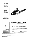
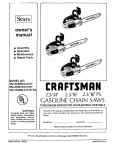
[Sears I
operator's
manual
•
•
•
•
Assembly
Operation
Maintenance
Repair Parts
MODELNO.
358.3550602.3/16" AV
358.35507O
2.3/16" AV -PS
--
.........
i
,,
,
,
..
[RRFTSMRN
2.3/16" AV
2.3/16" PS.AV
GASOLINE CHAIN SAWS
THIS CHAIN SAW IS FOR OCCASIONAL USE ONLY.
i
i
WARNING:
ii,
,, ,,
,|,11,
,,
, i
,
..
,
,,,
Record in the space provided below the Model No. and Serial No. of
your saw. These numbers are located on the starting instructions
decal.
Carefully mad and follow
Safety Rules, Precautions
and Operating
Instru¢,
tions. Failure to do so can
result in serious personal
injury.
Model No.
Serial No,
Retain these numbers for future reference.
,
Sears,
66378-1-12084-2-17884
rl
Roebuck
i
and
Cx_., Chiea_),Ill.
60684
U.S.A.
PRINTED IN U. S. A.
FULL ONE YEAR WARRANTY
ON GASOLINE CHAIN SAW
(Excluding Bar, Chain, Spark Plug, Air Filter and Starter Rope)
For one year from date of purchase, when you maintain, Iubricate, and tune up this chain saw according to the operating
maintenance
instructions in the operator's manual
Sears will repair defects in material or workmanship in this gasoline
chain saw at no charge.
This warranty excludes the bar, chain, spark plug, air fiiter, and starter rope which are expendable parts and become worn
during normal use.
if thiSchainsaw is used for'commem_lor rentalpurposes
_,this wan'antyappliesfor only30 daysfrom dateof purchase.
WARRANTY SERVICE IS AVA1LABLEBY RETURNING THE CHAIN SAW TOTHE NEAREST
SEARSSERVICE CENTER INTHE
UNITED STATES.
',_:
::
_
' •
: '
Thiswarrantygivesyou specificlegal:rightS,and:youmay alsohave otherrightswhichvaryfromstate to state.
Sears,Roebuckand Co., SearsTower, Dept. 698/731A, Chicago,IL 60684
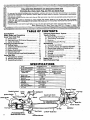
TABLE
OF CONTENTS
Specifications
............................
Safety Rules and Precautions ...............
Know Your Chain Saw .....................
A. Introduction ...........................
B. State anti, Local Ordinance Requirements...
C. Carton Contents ........................
Preparing Your Saw For Use ......
".............
A. Getting Ready ..........................
B. Attaching the Barand Chain ...............
C. Chain Tension ..........................
D. Engine Fuel Mixture .....................
E. Bar and Chain Oil ........................
F. Optional Muffler Heat Shield Assembly ;...
Using Your Saw ...............
- .............
A. Pre.Operation Checks ...................
B. Starting Instructions ....................
C. Controlling Kickback ....................
Using the Power Sharp ® System ...............
12
Types of Cutting .............................
13
A. Basic Cutting Technique .................
13
B. Tree Felling Techniques .................
14
C. Bucking ................................
15
D. Debranching and Pruning .............
_.._16
Maintenance ...............................
17
A. Guide Bar and Chain ...........
; ........
17
B. Ignition, Cooling, and Exhaust Systems .... 19
C. Starter Rope Repair and Replacement .......
20
D. Carburetor Adjustments ..................
21
E:: Air Filter ...............................
22
F. Storage ...............................
23
G. Maintenance Accessories
...............
23
H. Troubleshooting Chart ..................
24
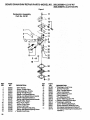
Repair Parts .............................
25-30
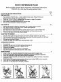
Quick Reference Page ........................
31
2
3
5.
5
5
5
6
6
6
7
8
9
9
10
10 ;
10
11
SPECIFICATIONS
MODEL
_
':_.355060(2.3/.1_.6")I. 3ss_SOTO(2_tEP.S:}
CU. tN. DISPLACEMENT
2.3 cu. in.
GUIDE BAR- LO-KICK®
CHAIN -ORI=GON ¢
GUARD LINK
16" Sgrocket
I
SPARK PLUG ""
SPARK
le'-sp,ocket
Nose
3/8 Pitch LoW P_ofile
Power Sltarp¢ Chrome Cutters
56 Drive Unks
" " "" " ' 3t_PitchLowPro_le
'
: XtmG_rd_ChromeCut_srs
,,
:
56 D_eUnks
Champio'n CJ-8
,
,,,
PLUG GAP
IGNITION
.025":
•
Solid State:
MODULE AIR GAP
FUEL MIX
.010 - .014""
GasolinelOi|
MUFFLER
OILER SYSTEM
FUEL TANK CAPACITY
OIL TANK
':'
"'
Mixture
- 16:t
S_rk Arresting.
Automatic
,
.
11.6 OZ. (343 .cc.)
6:6 oz (195 co:)
Throttle Trigger
Throttle Lockout
Choke
Fuel Cap
Ignition Switch
ontrol Handle
No.
Starter Handle
Fuel Ca
Oil Cap
(Power Sharp®Knob
2
:
Lo-Kicke Guide Bar
::
......
Handlebar
: _ " :_ '
.......
SAFETY
RULES AND PRECAUTIONS
WARNING!
Because a chain saw is a high-speed wood-cutting tool, special safety precautions
must be observed to reduce the risk of personal accidents. Careless or improper use
may cause serious injury,
A.
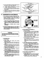
KNOWYOUR
To reduce the hazard of kickback:
SAW
1. Hold the saw firmly with both hands. Left hand
on front handle bar, right hand on rear handle
whether you are right-handed or/eft-handed.
Never use the saw withone hand.
2. Do not overreach.
3. Do not let the tip of the guide bar contact the
ground, another log, branch, or any other
obstruction.
4. Begin and continuecutting atfuilthrottle.
5. Cut one log at a time.
6. Use extreme-caution when re, entering a previouscut.
7 Do not attempt plunge cuts.
8. Watch for shifting logs or other forces that
could close a cut and pinch the chain.
9. Do not out above shoulder heighL
10. Follow manufacturer's
chain sharpening
and maintenance
instructions.
Keep the
chain properlytensioned. Check tension at regular intervals with the engine stopped; never
with the,engine running. Make surethe bar
clamp nuts are securely tightened aiter tensioning the chain.
11. Use the Guard Link Chain and Lo-Kick ®
Guide Bar designed for your saw to reduce the
hazard of kickback.
Read your Operator's Manual carefully until
you completely understand and can follow all
safety.rules and operating instructions before
attempting to operatethe unit.
2. Restrictthe
use,of your saw to adult users
who understand and follow the safety rules,
precautions,
and operating
instructions
found in this manual.
14
B.
PLAN
,
AHEAD
personal protective gear. AIuse steel-toed safety footwear with non-stip soles; snug;
fitting
clothing with
reinforced
cutting resistant inserts; heavy-duty non-slip
gloves;appropriate eye protection such as nonfogging, vented goggles or face screen; an approved safety hard hat, and sound barriers meat
plugs or mufflers to protect your headng. Regular
users should have hearing checked regularly as
chain saw noise may damage hearing.
Keep children, bystanders, and pets out of the
work area.Do not allow other people to be near
the chain saw when starting or operating the chain
SaW.
AVOID
3. Do not handle or operate a chain saw when. you
D,
are fatigued, ill, or upset; or if you have taken alcohol,, drugs or medication. You must be in "
good physical condition and mentally alert. Chain
saw work is strenuous. If you have any condition
that might be aggravated by strenuous work,
checl_-W!_ your doctor before operating a chain
Do notlattempt to use your saw during bad
weather, conditions such as strong wind, rain,
snow,e_., or during darkness.
To avoid Pushback:
1.
5. Plan your sawing operations carefully in ad....
,
vance; :Do not start cutting until you havea clear
, : •
work area; secure footing,, and if you are felling
_ ....
2.
trees_ a_planned retreat path.
3.
'....
:
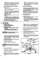
C.
GUARD
AGAINST
KICKBACK
: _
_
Kickback can lead to dangerous loss of control of
the saw and possibly cause serious personal injury. Kickback is the upward and backward motion of
the guide bar that occurswhen the moving chain contects an object at the tip ofthe guide bar.
FORCES
Pushback and Pull-in occur when the chain is
suddenly stopped by being pinched; caught, or.
by contacting a foreign object in the wood. This
results in a reversal of the chain force used to cut
wood andcauses the-saw to move inthe opposite direction of chain rotation,'resuiting-in loss of control
and possiblesenous personal injury.
saw.
°
REACTIVE
Be extremely aware of situations or obstructions that may cause material.to pinch the top of..
orotherwisestopthechain.
,
:
.
Do not cut more than one log at a time. ......
Do not twist the saw as the baris withdrawn
from an under-cutwhenbucking. ,
• To avoid PulHn:
_
1."Always begin cutting with the engine at full
throttle and the saw housing against the
wood.
2. Use wedges made of plastic, wood, or light
alloy (never of steel or iron) to hold the cut open.
3
"
E.
HANDLE
FUELWITH
CAUTION
'G.
1. Eliminate all sources of sparks or flame in the
areas where fuel is mixed, poured, or stored.
There should be no smoking, open flames, or work
that could cause sparks.
2. Mix, pour and store fuel in a well-ventilated
area, on bare ground, and in an approved,
marked container.
3. Wipe up all spilled fuel before starting your
SaW.
OPERATE
YOUR
SAW SAFELY
1. Do not operate a chain saw that is damaged,
improperly
adjusted, or not completely and
securely assembled.
2. Do not operate the saw from a ladder or in a
tree.
3. Position all parts ofyour body away to the side
of the saw chainr protrudingto the left of cut when
the engine is running.
4. Cut wood only. Do not use to pryor shove away
limbs, roots or other objects.
S_ Make sure the chain will not make contact before starting the engine. Never try to start the
saw when the guide bar isin a cut or kerr.
6. Use extreme caution when cutting small size
brush and saplings. Slender matedai may catch
the saw chain and be whipped toward youor pull
you off balance.
7. Be alert for springback when cutting a limb that
is under tension so you will not be struck by the
limb or saw when the tension inthe wood fibers is
released.
8. Do not put pressure on the saw at the end of
a cut. This could cause you to lose control when
the cutis completed.
9. Stopthe engine before setUng the saw down.
MAINTAIN
WORKING
YOUR
ORDER
SAW
IN
GOOD
1. Have all chain saw service performed by your
authorized service dealer center, other than the
items listed in the maintenance section of this
manual.
2. Keep fuel and oil caps, screws and fasteners
securelytightened.
3. Keep the handles dry, clean, and free of oil or
fuel mixture.
4. Make certain the saw chain stops moving
when the throttle trigger is released, if it does
not, refer to page 21 for correct carburetoridle adjustment instructions.
5. Stop the saw if the chain strikes a foreign ob -=
ject. Inspect the unit and repair or reptace parts as
necessary.
"
6. Disconnect the spark plug before performing
any maintenance except for carburetor adjustments.
7. Never modify your saw in any way. Use only attachments supplied or specifically recommended
by Sears.
4. Move at least 10 feet (3 meters) away from fuel
and fueling site before startingthe engine.
5. Do not smoke while handling fuel or while
operating the saw.
6. Turn the engine off and let your saw cool before removing the fuel tank cap and refueling
the unit.
7. Let the saw cool in a non-combustible area, not
on dry leaves, straw ,paper, etc.
F.
r
H.
CARRY
SAFELY
AND
STORE
YOUR
SAW
1. Hand carry the unit with the engine stopped,
the Muffler away.from your body, and the Guide
Bar and Chain to the rear covered preferably with
a scabard.
2. Before transporting in any vehicle orstodng in
any enclosure, allow your saw to cool compistely, cover the bar and chain and properly secure to avoid turnover, fuel spillage or damage.
3. Drain oiland fuel tank before storing for more ._
than 30 days.
4. Store in a dry area out of the reach of children
and away from where fuel vapors can reach an
open flame from hotwater heaters, furnaces, etc.
Exposure to vibrations through prolonged use of chain saws may produce Whitefinger disease (Raynaud's
phenomenon). This phenomenon reduces the hand's ability to feel and regulate temperature, produces
numbness and burning sensations and may cause nerve and circulation damage and tissue necrosis. An
anti-vibration system designed to reduce engine vibration is available on many Sears models and is
recommended for those using chain saws on a regular or sustained basis.
An anti-vibration system does not guarantee the avoidance of Whitefinger disease. Continual and regular
_ usersshould monitor closely their use of chain saws and physical condition.
4
KNOW
A.
YOUR
CHAIN
SAW
INTRODUCTION
C.
CARTON
CONTENTS
After you unpack the carton:
The information found in this manual will help
you properly prepare your chain saw for use,
understand how to operate your saw safely, and
perform maintenance required to keep your unit
in top working condition
1. Check the contents against the list below.
2. Examine the items for damage.
3. Notify your Sears store immediately ff a part
is missing or damaged.
Your saw has been designed with safety in mind and
includes the following safety features as standard
equipment,
Spark Arrestor
Handguard
Counter-Vibe® Vibration System
Lo-KickcGuide Bar
Guard Link Chain
The chain saw should never be operated unless
these devices are properly instailed_on theunit.
The _-Kick_ Guide Bar and Guard Unk Chain have:
been designed to help reduce the hazard of
KICKBACK. You should thoroughly read and understand the section, =CONTRO_ING KICKBACK" on
page 11 before operating the saw.
Sm
STATE AND lOCAL
REQUIREMENTS
•
ORDINANCE
Your saw has been furnished with an approved
Spark Arrestor Screen which is required in some
areas by law. You are legally responsible for seeing that the Spark Arrestor is propedy maintainedin_these areas. Failure todo so could sub,
ject you_to liability or to a fine. See Spark Arrestor maintenance, page 19.
Check with your state conservation or forestry
department about regulations concerning oper.
ating your saw on forest, brush, or grass covered
areas,_IL
U.S. forest land and the states of
Califomi_
Maine, Washington and Oregon require many internal combustion engines to be
equippedwith a temperature limiting muffler by
law. Such laws require fitting your saw with an
additional muffler heat shield.
A shield which meets these requirements can be
purchased at your Sears Service Center as an
optional accessory kit. Ask for Muffler Heat
Shield Kit, Repair Part No. 69037.
0
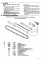
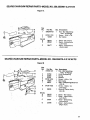
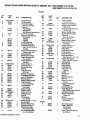
CARTON CONTENTS
Key No.
1 Powerhead
2
Guide Bar
3
8 oz. can 2-cycle Engine.Oil
-Loose parts Bag (Not Shown)
Qty.
1
1
1
1
LOOSE PARTS BAG CONTENTS
4
5
Operator's Manual (Not Shown)
Chain
Bar Adjusting Tool
1
1
1
Figure I
5
PREPARING
A.
GEl"rING
YOUR
SAW
READY
FOR USE
.........
_
2. HAVE THE FOLLOWING AVAILABLE:
1, READ
YOUR
OPERATOR'S
MANUAL
CAREFULLY.
Your Operator's Manual has been developed
to help you prepare your saw for use and to
understand its safe operation. It is important
that you read your manual completely to
become familiar with =the unit before you
begin assembly.
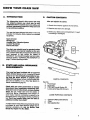
B.
ATTACHING
THE
BAR
AND
CHAIN
a.
b.
.... c.
d.
Protective gloves
Approved, markedfuel container
One gallon regulargasoline
One-half pint, 2-cycle, air-cooled engine oil
provided with your unit.
e. Barand Chain Lubricant (see page 9.)
f. Bar Adjusting Tool provided with your unit.
One end of the tool serves as a wrench; the
other can be used as a screwdriver. No other
too! is necessary for assembly.
_
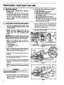
7, Lower the Guide Bar; fit the adjusting
pin
into the round hole below the large slot; fit
the large slot on the mounts on either side of
the Bar Stud. Figure 3 and 5,
• Your saw is equipped with a Lo.Kick _ Guide
Bar and a Guard Link Chain designed to help
reduce kickback.
._
• Always use the Lo-Kick_ Guide Bar, and r
Guard Link Chain designed for your par.
ticular chain .saw, when replacing these
parts.
_
,
8. Hold the Guide Bar against the saw frame
and install the Bar Clamp.
.
tCAUT!ON:{ Wear protective gloves when harv'
dling or operating your saw; The chain is sharp _
and can cut you even when it isnot moving!
1. Remove the following parts as shown
Figure 2, using the Bar Adjusting T0ol
pro-,
vided with the unit.
_
II
in
a. BarClamp Nut.
b. Rear BarCtamp Screw.
c. Bar Clamp.
Figure 2
2. Turn the Adjusting Screw counterclockwise
to move the Adjusting Pin almost as
far as it will go to the rear. Figure 2.
3. Hold chain with
Figure 3.
cutters facing
as shown in
4.Place
chain
over
andbehind
theCtutch
drum,
onto the sprocket. Figure 3.
5. Place the Guide Bar on the saw by fitting the
long slot in the Guide Bar over the Bar Stud.
Figure 4.
BAR STUD
.
r!ll ,,
i i
.
Figure 3
NOTE: Be sure the Guide Bar is positioned
with the adjusting pin hole below the large
slot.
I
Never install the bar upside down to avoid increasWARNING!
ing the hazard of kickback.
=.......
_1
6. Hold the Guide Bar at a 45 degree angle to
the saw and fit the chain into the Guide =Bar
grooves -- first, the top groove and then, the
bottom groove.
Figure 4
6
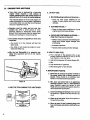
9. Secure the Bar Clamp with the Bar Clamp .....
Nut, finger tight only,
NOTE: The Bar Clamp Nut must be slightly
loose for the chain to be tensioned properly::
Securely tighte n Bar Clamp Nut after chain
is tensioned.
.
:.
10. Replace. the
tighten.
11. Follow:"Chain
Rear Bar Clamp
Screw
and
Tension" instructions below.
Figure 5
C.
• Chaintension
is very important:
_
5. Check the Rear Bar Clamp Screw to be sure
it is secure.
loose chain will wear the bar and itself,
6. Recheck chain tension.
--a loose chain can jump off the barwhile
you are cu:tting.
•
,
.1.
--a
JcAUTION__Always wear gloves when handling
the chain. The chain is sharp and can cut you
even when iris not moving!
tight chain can damage the saw andlor
break.
• Chain tension is correct when the chain:
:_
--can be lifted about 1/8" from the Guide Bar
at a point :near the middle of the bar, and ..... '
--will
move-freely around the bar.
• The chain stretches during use,
when new. Checktension:
-- each time the saw is used,
....
especially
_
-- more frequentJywhen the chain is new
TURN
as the,chain warms up to normal operating temperature
"'
,
.....' _
_._
TO LOOSEN
TENSION
• The Bar, Clamp Nut must be slightlyloose for
the chain to be propedy tensioned.
_
Figure 6
1. Hold the tip of the Guide Bar upand turn the L
Adjusting Screw clockwise just until the
chain does not sag beneath the Guide Bar.
Figure_6._._
_
_ • ' __ •_
i
2. Check the tension by lifting the chain from
the Guide Bar at the center of the bar. Figure
CHAIN CAN BE
LIFTED 118"WHEN
TENSION
'
118"
3. Continue adjusting the Adjusting Screw until
the tension is correct,
......
=
_
o
4. Hold the tip of the Guide Bar up and tighten
the Bar Clamp Nut with the Bar Adjusting
Tool.
:
illlllllqlllllllll
fl
Figure 7
7
11
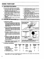
ENGINE
FUEL MIX"rURE
• Your chain saw is powered by a two-cycle
engine which requires a fuel mixture of
regular gasoline and a high quality engine oil
specially made for 2,cycle, air-cooled engines.
2. DO NOT USE:
• BIA Oil (Boating
The internal design of the 2_ycleengine
re-•
quires lubrication of moving parts. Lubrication
is provided when you use the recommended
mixture of gasoline and oil.
InstituteofAmeHca)--
--Does
not have proper additives for aiP
cooled, 2-cycle engines and could cause
damage.
• AUTOMOTIVE OIL-• Gasoline must be clean and not over two
months old. After a short period of time,
gasoline begins to chemically break down
and will form compounds that can cause hard
starting and damage in 2-cycle engines.
The c0_t
importanL
k
-- Does not have proper additives for 2-cycle
engines and could cause damage.
• GASOLINE CONTAINING ALCOHOL-(High Test, Premium or Gasohol)
measure of gasoline to oil is very
Stiffens critical carburetorfuel metering elements and causes engine damage from
overhealJng.
--Too much oil in the mixture will foul the
spark plug.
Increases vaporiock.
--Too little oil wilt cause the engine to overheat and freeze up_
• Mix the fuel thoroughly in a separate container since gas, line and oil do not readily
combine.
FUEL
CAP
_ Attracts water causing corrosiondamage.
3. HOW TO MIX FUEL
a. Pour one-half of the gasoline into an approved marked container. Do not try tomix
fuel directly in the fuel tank.
b. Add entire measure of 2-cycle Engine Oil.
c. Mix.
d. Add remainder of gasoline.
e. Mix thoroughly for one minute.
4. IMPORTANT
Figure 8
1. USE THE FOLLOWING
""_RS
_
-}" __
/
--OR-.__e_G,NEO,L
....J= _
._
....
16:1
8
Eliminate all sources of sparks or flame in
the areas where fuel is mixed, poured, or
stored. There should be no smoking, open
flames or workthat could cause sparks.
b°
Mix, pour and store fuel in an approved,
marked container and in a well-ventilated
area. Gasoline vapors are harmful to your
health and are a serious fire hazard. Use afunnel or spout when pouringfuel.
OIL_,.,,J
c. Avoid over filling the fuel tank. Allow 3/4 inch
for expansion. Tighten Fuel Cap securely. Figure8.
d.
I
R-coo o,2.cYcL
!
ENGINE
a.
FUEL MIXTURES:
#,1 ._=ss_""1
ls:1
POINTS
e.
Wipe up all fuel spills. Wipe off fuel spilledon
the saw before using.
Move at least 10 feet (3 meters) away from
fuel and fueling site before starting the engine.
E,
BARAND
CHAIN
OIL
e The guide bar and cutting chain require con.
stant lubrication
in order to remain in
operating condition. Lubrication is provided
by the automatic oiler system when,the oil
tank is kept filled.
--Lack of oil will quickly ruin the bar and
chain.
--Too little oil will cause overheating shown
by smoke coming from the chain and/or
discoloration Of the guide bar rails.
2. HOW TO FILL THE OIL TANK
a. Turn saw on its side with oil cap UP. Figure
9.
b. Loosen cap slowly; wait for pressure in the
tank to be released before removing the
cap.
c. Fill the oil tank.
d. Replace the oil cap securely.
3. IMPORTANT
POINTS
a. Fill the oil tank each time you refill the fuel
tank to ensure there will be sufficient oil for
the chain whenever you start and run the
saw.
Use Sears Bar and Chain Lubricant #71-36554
or clean SAE 30W oil.
e
lo
In freezing weather oil wiU thicken, making it
necessary to thin bar and chain oil.with a
smaflamount of Diesel Fuel #1 or Kerosene.
Bar and chain oil must be free flowing for the
oil system to pump enough oil for adequate
lubrication.
USE THE FOLLOWING:
30°F or above--Lubricant--undiluted.
30°F!-0°F
--95% Lubricant to
5% Diesel Fuel #1
or Kerosene.
Below 0°F
--90% Lubricant to
10% DieseiFuet #1
or Kerosene.
b. It is normal for a small amount of oil to appear under the saw after the engine stops
due to oil draining from the bar and chain.
CAP
Figure9
Fal
OPTIONAL
MUFFLER
SHIELDASSEMBLY
HEAT
The following instructions have been included
to help you install the optional Muffler Heat
Shield Kit, Repair Part No. 69037. This kit will
provid_;your saw with a temperature limiting
mufflet'_which may be required by law in some
states. See State and Local Ordinances, page5
for furtl_er information.
1. Remove the screw located in the center of the
muffler body. Figure 10.
2_ Remove the muffler cover from the muffler
body/and discard.
NOTE: Do not remove other muffler parts, if
other parts are removed, see muffler assembly in Figure 43, page 19.
3. install the temperature
Figure 11.
limiting muffler body.
4. Replace screw and tighten
securely.
_--AUTIO--O-N-_
Do not use an air Wrench to
tighten the screw to avoid overtightening
parts and damage.
Figure11
USING
Am
YOUR
SAW
PRE-OPERATION
CHECKS
_=
Each time before operating your saw, always:
,_'Check the saw chain. The chain should be
sharp and at the correct tension.
6. ,,-Check the fuel tank and oil tank. Both tanks
should be filled.
7. ,,,Check the handles. Handles should be dry
and free of fuel mixture and oil.
8. ,,-Check weather conditions. Do not use your
saw at night or during bad conditions such
as strong wind, rain, snow, etc.
g°
,,'Check the work area. Keep children,
bystanders, and pets a safe distance away
from the work area when starting or operating
the saw.
=
1. ,_Check over safety rules and precautions in
this manual. Make certain you completely
understand and can apply each one.
2. ,,,Check personal protective gear. Always use
appropriate eye, hearing, and head protection
devices; safety footwear, protective gloves;
and snug.fitting clothing.
3. ,,,Check the saw for loose bolts, nuts, or fittings. Tighten, repair or replace parts as
4. ,,,Check the air filter. Clean the filter before
operating the unit.
am
STARTING
1. IMPORTANT
INSTRUCTIONS
•
(Refer to "SpecificaUons,,'
page 2, for location of controls.)
POINTS
a. Hold saw firmly with thesaw chain free to
turn without contacting any object. Push
saw away from you with your dght hand
while pulling the starter rope with your left
hand. Figure 12.
b.
C.
d.
e.
Use no more than 15-18 inches of starter
rope per pull. Using the full length oflhe rope,
may cause it to break. Do not let the starter
rope snap back. Hold the handle and let the
rope rewind slowly.
Use only 15-18 inches
of rope Per Pull.
Figure 12
Pull rope no more than 5-6 times to avoid
flooding the engine. 8-10 pulls may be required for a new unit, a saw that has been
stored, a refueled unit which has run out of
gas.
Release the trigger after
allowing the engine to idle.
not move when the engine
tion is required, refer to
justments, page 21.
engine starts,
The chain must
idles. If correcCarburetor Ad-
Stop engine by moving the ignition switch
to the "STOP" position Figure 13.
2. STARTING
I
I
START-_P_I=STOP |
Figure 13
!
F"''
OFF
Figure 14
,
,.
J
WARNING!
Avoid bodily contact with the muffler When starting a warm engine to avoid serious bums.
PROCEDURE
a. Cold Engine
b. Warm Engine
c. Refueled Engine after
running out of gas
d. Flooded Engine
e. Cold Weather starting
TurnChoke Moveignition Squeeze Pullstarter
toFull
switch
to
trigger ropeuntil
Choke
Start
eaginefires
X
X
X
5-6times
Chokeoff)
X
X
X
X
X
8-!0tiimes
(chokeoff)
X
X
X
X
X
-5-6times
Tam
Choke
off
X
X
-half-choke*
Pullstarter
rope Release
sharply
until
trigger
engine
runs
X
X
X
1-2times
X
X
X
X
X
X
(out0fcut)
" Allow engine to warm up on half-choke, then move choke tothe
choke at the "on" or "'half" position. Figure 14.
10
"off"
position. Do not cut with the
C.
CONTROLLING
KICKBACK
Kickback is a dangerous reaction that can cause
serious personal injury. Carefully =udy this manual before you make the first cut with your new
saw. You must understand what causes kickback,
how you can reduce the chance of kickback, and how
you can remain in the best control of the saw if
kickback does occur.
1. WHAT CAUSES
KICKBACK
Kickback can occur when the moving chain
contacts an object at the tip or nose of-the
guide'bar. This contact causes the chain to dig
into the object and stops the chain for an instant.
The result is a lightning fast, reverse reaction
which kicks the saw tip up and back toward the
operator. The operato r can lose control ofthe saw
and the.cutting chain can cause sedous personal
injurY:if,itcontacts any part ofthe body.
/
Fig= is
•
\
A
/
AvoiD'
o=..uc.,o.
t
7
;,.
2. REDUCETHE
CHANCE OF
KICKBACK
a. Recognize that kickback can happen. By
understanding and knowing about kickback,
you are better equipped to deal with an occurrence,
b. Never let the movingchain contact any objectat the tip of the guide bar. Figure 15
c. Keep the working area free from obstructions such as other trees, branches, rocks,
fences, stumps, etc. Figure 16. Eliminate or
avoid any obstruction that your saw chain
- could hit while you are cutting through a particular log or branch.
d. Keep your saw chain sharp and properly
tensioned. A loose or dull chain can increase
the chance of kickback.
.
,_
e. Begin and continue cutting at fult throttle.
"
if the chain is moving ata slower speed, there : •
is greater chance for kickback tOoccur.
'
.f. Cut one log at a time.
g. Use extreme.caution when re-entering a
previous cut.
"
h. Do notattemptplunge cuts.
i. Watch for shifting logs or other forces that
could close a cut and pinch or fall into the
chain.
j. Use the Lo-Kick_Guide Bar and Guard Link.
Chain specified for your particular saw.
'
These devices have been designed to reduce
the hazard of kickback.
k. Use extra caution if your saw is-equipped
with the Power Sharp'-" System. The Power
SharP_ saw is equipped with a_I'D-Kick" Guide
Bar and a Guard Link Chain. However, due to
the chain requirements of the built-in sharpen- .
ing mechanism, the kickback force from the .
Power Sharp-" chain may be greater than that
from other Guard Link chains.
3. MAINTAIN
.,
WORKING AREA _
Figure 16
i
NEVER
REVERSE
HAND
POSITIONS
STAND
TO THE
LEFT OF
THE SAW
ELBOW
LOCKED
L
THUMB ON
UNDER SIDE
Figure 17
Keep a good firm grip on the saw with both
hands. Figure17. A firm grip can neutralize ,_::i _-_
kickback and help you maintain contto!of the
saw. Keepthefingersofyour left hand encircling and yourleft thumb under the front handlebar. Keep your right hand completely
around the rear handle whether youare right
handed or left handed. Keep your left arm
straight withthe elbow looked....
bq
Position .your left hand on the front handlebar so it is in a straight line with your
right hand on the rear handle. Figure!7:
Never reverse rightand left hand positions.
ci
Stand with your weight evenly balanced on
both feet.
d. Stand slightly to the left side of the saw, to
keep yourbody from being in a direct line
with the cutting chain. Figure 17
e,
Do not overreach. You could be drawn or
thrown off balance and lose cor_trolof the saw.
f. Do not cut above shoulder heighL It is diffi- ......
cult to maintain control of the saw above
shoulder height.
11
a°
,_.,r-- ,.__ o_,
f
THE BESTCONTROL
USING
THE POWER SHARP®SYSTEM
Model 358.355070 is equipped with a Power Sharp ®
System that will perform approximately 80% of the
sharpening necessary for the saw chain. The Power
Sharp® System utilizes a built-in grinding stone to
sharpen the cutter top plates and set depth gauges.
As the built-in sharpener is used, the cutter side
plates gradually will be altered. About every 3rd to
5th time the Power Sharp® System is used, hand fiting isrequired to correct the cutter side plates.
• Sharpen the saw chain when:
--wood chips become small and powdery.
Wood chips made by the chain should be
about the size of the teeth of the chain.
--saw cuts to one side.
--saw has to be forced through the cuL
A.
AUTOMATIC
HAND
• Replace the sharpening stone when a new
Power Sharpe chain is installed. See instructions, page 13.
• Remove the sharpening stone if a standard or
conventional
chain is substituted for the
Power Sharp® chain. See instructionsfor removing the sharpening Stone and Carder Assembly,
page 13. Use replacement chain for Model
358.355060 (2.3/16"), Stock No. 71-3629. Follow
conventional chain sharpening instructions on
page 17.
ICAUTION:]Aiways wear gloves when handling
the chain. The chain can cut you even though
it is too dull to cut wood.
SHARPENING
1. Stop the engine.
2. Place saw on a solid, flat surface; and ensure
that the chain will not contact any object.
3. Adjust the chain with proper tension. Refer to
Chain Tension, page 7.
4. Start engine and operate at half throttle.
5. Press the Power Sharp® Knob down until
you feel the sharpening stone lightly contacting the chain: Figure 18.
6. Maintain constant; light pressure on the
Power Sharp® Knob while moving the knob
side to side for 5 seconds.
7. Release Power Sharp®
Knob and + stop
engine.
8. Inspect chain cutters.
NOTE: A properly sharpened cutter will show
grinding marks across its entire width. Figure
19.
Ell
(MODEL358.355070)
INSTRUCTION
DECAL
POWER SHARP _ KNOB
Figure 18
TOP VIEW OF CUTTER
INSPECT CUTTERS FOR GRINDING MARKS
FigurelS
FLUNG
Sharpen saw chain side plates by hand after
every 3rd to 5th time the Power Sharp ® system
isused.
1. Stop the engine.
2. Adjust the chain for proper tension, page 7.
3. Support the square rod on the file holder(with
+5/32" round file) on cutter top plate. Figure 20.
NOTE: Work at the midpoint of the bar, moving the chain forward with a screwdriver as
each cutter is filed.
4. Hold the file holder level with the 22 ° guide
mark parallel to guide bar. Figure21.
SUPPORT THE SQUARE ROD
ON RUE HOLDER FLAT "1
/_'_ROUND
ON TOP OF CUTTER
__/'
-.-_L",..L.)==,_
TOP ___."
FILE
DEPTH
GUAGE
KI
PARALLEL TO
CENTER OF
THEGUIDE
BAR
PLATE
Figure 20
12
Figure 21
5. File from inside toward outside of cutter,
straight across, in one direction only. Use 2 or
3 strokes per side plate edge. Figure 21.
SIDE
PLATE
tz,
SIDE PLATE
NOTE: Avoid hitting the top edge of the cutters when filing the side plate.
Maintain a 1132" side plate projection. Figure
22.
7. Fite all side plates on one side of the chain,
then move to the other side of bar and file remaining side plates.
.
REPLACE
OR REMOVE
STONE
AND CARRIER
Figure 22
THE
ASSEMBLY
1. Removebarclamp.
2. Remove screw holding Stone and Carrier
Assembly. Figure 23.
3. Discard old.assembly.
4. Reverse:_procedure to install new assembly.
5. Tighten screw securely.
STONE &
CARRIER
NOTE: Be careful to not overtighten. (Torque
to 20-25 inch pounds.)
Figure 23
6. Reassemble saw.
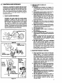
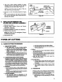
TYPES
A.
BASIC
le
OF CUTTING
CUTTING
TECHNIQUE
IMPORTANT POINTS.
a. Cut wood only. Do not cut metal, plastics,
masonry, non-wood, building materials; etc.
b. Stop the saw if the chain strikes a foreign
object- Inspect theunit and repair or replace
parts as necessary.
c. Keep the chain out of dirt andsand. Even a
small amountof dirtwill quickly dull a chain and
thus, increase the possibilityof kickback.
2. UNDERSTAND
REACTIVE FORCES
Pushback and Pull-in occur when thechain is
suddenly stopped by being pinched, caught,
or by contacting a foreign object in the wood.
This results in a reversal of the chain force used
to cut wood and causes the saw to move in theLOppositeclir_on of chain rotation, resulting in loss
ofcontrol and possible serious personal injury,
• Pushback:
--occurs when the chain, on top ofthe bar, is suddenly stopped when the top of the bar isused for
cuffing.
drives the saw straight back toward the operator,
possibly causing loss of saw control
• To avoid Pushback:
a. Be extremely aware of situations or obstructions that may cause material to stop or
pinch the top ofthe chain.
b. Do not cut more than one log atatime.
c. Do not twist the saw asthebariswithdrawn
from an under-cut.
Pull-in:
-- occurs when the chain on the bottom of the bar
is suddenly stopped.
occurs when the spike or saw housingis not held
securely against the tree or limb and/or whenLthe
cut is not begun at fullthrottle.
Bpulls the saw forward, and could cause the
operator to lose control
• To avoid Pull-in:
a. Always begin cutting with the engine at full
throttle and the spike or saw housingagainst
the wood.
b. Use wedges made of plastic, wood, or light
alloy (never of steel or iron) to hold the cut
open.
3; PROCEDURE
Practice cutting a few small logs using the following technique to get the =feel"of using your saw
before you begin a major sawing operation.
a. Accelerate the engine to fulll throttle just before entering the cut by squeezing the Throttle
Trigger.
13
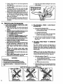
b. Begincutting with the
c.
d.
e.
f.
,
B.
g. Stop the engine before setting the saw down
after cutting.
i
i,i/
I TNE BOTTOM OF THE
I SAW FRAME AGAINST
A ,_
_.'_
{_ _
7"-
/
#L_
Figure 24
,, ,,; .....
TREE
FELLING
TECHNIQUES
ui: ¸
' r_
4'
.m
saw frame against the
Iog_.Figure 24.
Keep the engine at full throttle the entire time
you are cutting.
Allow the chain to cut for you; exert only light
downward pressure. If you force the cut, damage to the bar, chain or engine can result.
Release the throttle trigger as soon as the cut
is completed, allowing the engine to idle. Ifyou
run the saw at full throttle without a cutting
load, unnecessary wear can occur to the
chain, bar, and engine.
Do not put pressure on the saw at the end of
the cut to avoid losing control when the cutis
complete.
1. PLANYOUR
SAWING OPERATION CARE-:
FULLY IN ADVANCE
a. Ctear the workaraa. You need a clear areaali
b.
c.
d.
e.
f.
g.
h.
around .the tree where you can have secure
footing.
Studythe naturaiconditionsthat can cause
thetree to fall in a particular direction:
1.) The WIND direction and speed
2.) The LEAN ofthetree .............
3.) WBGHTED with BRANCHES on one side
4.) Surrounding TREES and OBSTACLES
Look for decay and rot. If the trunk is rotted,
it could snap aridfall toward the operator.
Check for broken or dead branches which
could fall on you while cuffing.
Make sure there is enough room for the tree
to fall. Maintaining a distance of 21,_ tree
lengths from the nearest person or other objects. Engine noise may drown out warning
call Remove dirt, stones, loose bark, nails,
staples, and wire from the tree where cuts
areto be made.
Plan to stand on the up-hill side when cutring on a slope.
Plan a .c.lcar retreat path to the rear. and
diagonalto the line of fall. Figure 26.
........
-
......
etc.
i)ONTt'iIlrIrOIIRSIBi_
LESS THAN 6"
a. lfyou knowthe direction offall:
1.) Ma$'.ea single felling:cut on the side away- ....
from the direct{onof fall
....
"
•
WARNING!
DONOTCUT:
-- near electrical wires or buildings.
uif you do not knowthe direction of tree fall.
at night since you will not be ableto see well.
_during
bad weather-- strong wind, snow, rain,
(licit tile lda=l_
Iion't €= &_tl= wl_
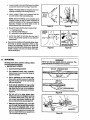
2..FELLING
SMALL TREES-IN DIAMETER
2.) Cut allthe waythrough.
3.) Stop the saw, put it down, and get away
quickly on your planned retreat path.
b.
3.
If you are not sure which way the tree will fall,
use the notch method described for felling
large trees.
FELLING LARGE
• OR MORE
TREES m 6" DIAMETER
The notch method is used to cut large trees: A
notch is cut on the side of the tree in the desired
direction of fall. After a felling cut ismade on the
opposite side of the tree, the tree will tend to fall
intothe notch.
NOTE: If the tree has large buttress roots, remove before making the notch. CUt into the buttresses vertically, then hodzontaily. FKjure25
a. Make the notch cut. Figure27. ,
1.) Cut the bottom of the notch first, through
1/3 ofthe diameter of the tree.
2.) Complete the notch by making the slant
cut.
3.) Removethe notch ofwood.
b. Make the felling cut onthe oppositeside ofthe
notch about 2" higher than the bottom of the
notch.
]NTB]BSIB _ONS
C.
Leave enough uncut wood between the felling .......
cut and the notch to form a hinge. Figure 28.
i
•
NOTE: The hinge helps to keep the tree from
twisting and falling in the wrong direction.
d.
Use a wedge if there is any chance 1hat;the
tree wiil not fall in the desired direction.
NOTE: Before the felling cut is complete, drive
wedges to open up the cut when necessary to
control the direction of fall. Use wood, plastic or
light;alloy wedges but never steel or iron, to
avoid kickback and chain damage.
e.
Be alert for signs that the tree is readyto fail:
1.) 'cracking sounds
2.) widening ofthe felling cut
3.) movementinthe ulSperbranches, ........
f. Asthe tree starts to fall, stop .the saw; put it
dowh, and get away quickly on your ptanned
retreat path. "
g. Be extremely =utiouS with partially fallen trees
that:may be poorly supported. When a tree
doesn't fall completely, set the saw aside and
pull down the tree with a cablewinch, block and
tackle or tractor. Do not cut it down with your .....
saw to avoidinjury;
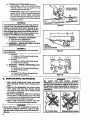
Co BUCKING
•.
•
Bucking is the term used for cuffing a fallen
tree to the desired log_size.
1. IMPORTAWI" POINTS
Rgure22
:=
WARNING!
Never turn the saw upside down to undercut. The
saw cannot be controlled in this position.
•
,,11
a. Cut only one log atatime.
1ST CUT PRESSURES;IDE
---_ 4-_
b. Cut shattered wood very carefully.
Sharp pieces of wood could be flung towardthe operator.
• _;
C°
Use, a. sawhorse to cut. small logs.
•Never allow another person to hold the
logwhile cutting and never hoidl_e log-
your!egorfoot
......
d.
e.
"KP_
Givespecial attention to logs under
strain to prevent the saw frompinching.Make the first cut on the compression side to relieve the stress on the log
Fig._S 29. ................
-
-_l
-.
....
.
._=__
-.__--
. lST•CUT, . SSU.ES,OE
....
DO"not cut in an area: where: logs,
limbs and roots are tangled such as
ina,blown down area. Drag the Iogs l _.
into acleararea before cutting by pul, : _z......
ling outexposed andcleared logsfirst:
_,_ i;
Make the first bucking cut 1/3 of the i__ _j : _i
way through the log and finishwith a
"
2/3 cut on the opposite side. As the
log is being cut, it will tend to bend. The
saw can become pinched or hung in the
log if you make thefirst cut deeper than .i. _i_............. "
1/3 of the diameter of the log.
2ND CUT
_-....+
:
im
Figure29
Rgure30
IV...__.....
~
2..TYPES OF CUTTINGUSEDFigure30.
Overcutting- beginonthetopsideofthelog
with the bottomof the sawagainst the log;
exert light pressure downward.
WEDGE USED TO
HOLD CUTOPEN.
-
Undercutting - begin on the under side of the
log with the top of the saw against the log;exert
light pressure upward. Dudng undercutting,
the saw wil! tend to push back at you, Be pre' pared for this reaction and hold the saw firmly
to maintain control....
WARNING!
if saw becomes pinched or hung in a log, don't try
to force it out. You could lose control of the saw resulting in personal injury and/or damage to the
saw. Stop the saw and drive a wedge of. plastic,
wood or light alloy into the cut until saw can be removed easily. Figure 31. Do not use a steel or iron
wedge to avoid idckback and chain damage.
Figure31
k
3. BUCKING--wrrHOl_
A SUPPORT
a. OvercUtwith a 1/3 diameter cut.
b. Roll tog over and finish withan ovemut:.
4. BUCKING--USING
SUPPORT (Figure
ANOTHER
32):
LOG AS A
USING
,,
ANOTHER
LOG AS A SUPPORT
Do not stand on theWARNING!
log being cut. The cut portion
will roll down hill.
Figure32
a. In areaA:
1.) Undercut 1/3 of the way through the log.
2.) Finish with an overcut.
b. In area B:
....!.) Overcut, 1/3 ofthe waythroughthe log..
' •2.) Finish with an undercut.
.....
5. BUCKING _ USING A STAND (Figure 33):
a. In areaA:
1 .) Undercut 1/3 ofthewaythmugh the log. ,
2.) Finish with an overcut.
b. In areaB:
1.) Overcutl/3ofthewaythroughthelog;
=
2.) Finish with an undercut.
D.
DEBRANCHING
i
2ND CUT
:
_
Ri_sqr
CUT
,WARNING!
BE ALERT
FOR AND
GUARD
AGAINST
KICKBACK. Do not allow the moving chain to contact.any other branches or objects atthe nose of
the guidebar when debranching or pruning. Allowing such contact could result in serious personal iniury.
' .......
alice.
16
CUT
Figure33
• Work sloWl_y, keeping both hands on the saw
with a fi_ grip. Maintain secure footing and ba !-
Never climb into a tree to debranch or prune. Do '
•not stand on ladders, platforms, a log or in any
position which might cause you to lose control of
the saw.
lS1" CUT
.:_ :
CUT
AND PRUNING
• Watch out for springpoles.
Use extreme caution
when cuffing small size limbs. Slender material
may catch thesaw chain and be whipped toward
you or puleyou off balance.
• Be alert for springback. Watch out for branches
that are bent or under pressure asyou are cuffing
to avoid being struck by the branch or the saw when
the tension in the wood fibers is released.
• Keep a clear work area. Frequently clear branches out of the way to avoid trippingover them.
.............
.....
1
DEBRANCHING
a. Limit debranching
to limbs shoulder
height or below. Always debranch a tree
after it is cut down, Only then can debranching
be done safely and pmpedy,
b. Leave the larger lower limbs to supportthe
tree as you work.
c. Start at the base of the felled tree and work
towardsthe
top, cuffing branches and
limbs. Remove small limbsw!th one cut. Figure34.
d. Keepthe tree between you andthe chain.
Cdt from the side of the. tree opposite the
branch you are cutting.
:
e. Remove larger, supporting branches with
the i/3,2/3 cutting techniques d_ribed
in
the bucking section.
1 .) Startwith an overcut
2.) Finish with an overcut
f. Always use an overcut to cut small and
freely hanging limbs. Undercutting could
cause limbs to fall and pinch the saw.
1 .) Undercut 1/3 of the way through the limb
near the trunk of the tree.
2.) Finish with an overcut farther Out from the
trunk.
3.) :Keep out of the way ofthe falling limb.
4.) Cut the stump flush near the trunk of the
tree:
Removesmail limbs
....
•
AND
CHAIN
/
Increase the service life of your Guide Bar and
Chain by:.
--Using:the saw properly and as recommended
in this manual.
--Maintaining correct Chain Tension, page 7.
--Proper lubrication, page9.
--Regular maintenance as described in this section.
;.....
_
_'
1. CHAIN
•
RRST PRUNING CUT
.........
• Make all adjustments or repairs (except carburetor adjustments) with:
--spa,rk:pl, ug wire disconnected
--engine COol 'as opposed to a unit that has
just been run.
.
GUIDBBAR
Figure34
SECONDPRUNING CUT
• Check 1he saw for loose bolts, screws, nuts
and fittings regularly. Loose fasteners can
cause an unsafe condition as well as damage
to your saw.
A good maintenance program of regular inspec=
tion and care will increase the service life and
help to maintain the safetyand performance of
your saw.
_
- ..
Am
one cut.
THIRD
PRUNINGCUT
2. PRUNING
..
:
;: ....
a. Limit pruning to limbs shoulder,height or
below. Do not cut if branches are higher than
your shoulder. Get a professional to do the
job.
b. Refer to Figure 35 forthe
pruning technique.
MAINTENANCE
with
t
WARNING!
All repairs, adjustments and maintenance .not de. scribedin the Operato_s.ManuaLshould
be per-:;
.formed by a qualifiedservicedealer.
LCAUTION:J Always wear gloves when handling
the chain. The chain is sharp enough to cut you
even though it is too dull to cut wood.
a. SHARPENING INSTRUCTIONS -Model 358.355060 (For Power Sharp®Model
358.355070, see page 12-13.)
Items required:
Gloves
5!32" file
6" file holder
MAINTENANCE
• Sharpen the chain when:
......
---wood chips are small and powdery. Wood
chips made by the saw chain should be
about the size of the teeth of the chain. _
w saw has to be forced through the cut. ......
•.-,saw cuts to one side.
_ _: _
•
'
•
Medium file
Depth Gauge Tool
1.) Stop engine.
2_) Adjust the chain for proper tension,
page 7.
3.) Work atthe midpoint of thebar, moving
the chain forward by hand as each cutter is filed.
17
4.) Sharpen cutters.
a.) Position the file holder with the
square rod on the top plate of the
cutter asshown in Figure36.
b.) Hold the fite holder level with the
30 ° guide mark parallel to the
center line of the bar. Figure 37.
SUPPORT FLATSIDE
OF FILE HOLDER
ON TOP OF
CUTTER
c.) File from inside toward outside of
cutter, straight across in one direction only. Use 2 or 3 strokes per cutting edge. Figure 38.
Figure 36
5.) Correct Depth Gauges.
a.) Place depth gauge tool (Catalog No.
71-36557) over each cutter depth
gauge. Figure 39.
b.) File level with the flat file if depth
gauge is higher than the depth
gauge tool.
HOLD30 ° GUIDE
MARK PARALLEL
TO THE
GUIDE BAR
30 °
c.) Maintain rounded front corner of
-depth gauge with a flat file: Figure
40.
i
Figure 37
NOTE: The very top of the depth
gauge should be flat withthe front half rounded off with a, flat rite.
b. CHAIN REPLACEMENT
1.) Replace the chain when cutters or links
break.
Rgure38
2.) See your Sears
Service Center to
replace and sharpen individual cutters
to match your chain.
3.) Always replace the worn sprocket when
installing a new chain to avoid excessive weartothe chain.
2. GUIDE
BAR MAINTENANCE
• Conditions which can require guide bar
maintenance:
_saw cuts to one side
--saw has to be forced through a Cut
--inadequate
supply of oil to bar and
chain.
Figure 39
MAINTAIN ROUNDED
CORNERS OF DEPTH
• Cheek the condition of the guide bar each
time the chain is sharpened. A worn guide
bar will damage the chain and make cutting more difficult.
' _,
_:_
Figure40
• Replacethe guide barwhen:
Mthe inside groove of the guide bar rails is
REMOVE SAWDUST
FROM THE
GUIDE BAR GROOVE
worn°
.the
guide bar is bent orcracked.
a.
Remove the guide bar to service.
b.
Clean oil holes at least once for
five hours of operation.
C.
eac.
Remove sawdust from the guide bar
groove periodically with a putty knife or _
a wire. Figure 41.
_.....
_:
_:
_
_
IIIIII]1 I
,
,
:
11
•
[1[
]
: Figu 41
I i
I
I
I
.......
I
r
i
d.
e.
Remove burrs by filing the side edges
of the guide bar grooves square with a
flat file. Figure42_
Restore square edges to an uneven rail
top by filing with a flat file: Figure 42.
m
•
i
CORRECT
GUIDE BAR
GROOVE
WORN GROOVES
FILE EDGES
SQUARE
Figure 42
B.
IGNITION,
COOLING
AND
EXHAUST
• Carbon deposits will build up on exhaust
• - ports;spark arrestor, muffler, and spark plug
as the_saw is used. All of these parts should
be •cleaned at the same time to prevent
engine damage, overheating, loss of power,
and hard starting.
• Clean parts:
--as required
--at least once for each 25.30 hours of
operation
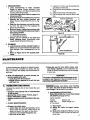
1. EXHAUST
SYSTEM
SYSTEMS
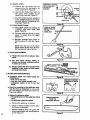
b.
Clean deposits from the electrodes of
the spark plug with a small brush or a
pocket knife.
NOTE: Be careful when removing,
cleanihg, gapping and replacing the
spark plug. tf it is damaged, it will not
work properly and must be replaced.
c. Set the gap:between the electrodes to
.025 using a wire or flat gauge. Figure
45.
d. Replace the spark plug.
• Carbon build-up on the exhaust system can
cause the engine toloose power in a cuL
• Keep the spark arrestor clean at all times.
• Replace the spark arrestor when breaks in
the screen are founcL
Items required:
Wire brush
3/8'_+wrench
HardW0od stick
a. Disconnect the spark plug.
b. Remove the muffler, baffles, and
screen. Figure43.
c. Pull the starter rope until the piston
moves far enough to close the exhaust
ports.
d. Scrape the carbon deposits from the
+;exhaust ports and surrounding exhaust
+chamber using a
hardwood stick.
Figure 44.
e. Blow out loosened carbon with corer
pressed air.
f. Clean the spark arrestor screen with a
•wire brush or replace if breaks in the
screen are found.
g:+.?Reassemble muffler parts.
2. SPARK
PLUG
• Keep the spark plug:
--clean
--pmpedy gapped (+025)
!
SPARK ARRESTOR SCREEN
Figure43
CLEAN
EXHAUST
PORTS
Figure 44
CHAMPION CJ-8 SPARK PLUG
• Maintenance is indicated when the engine
is hard to start.
Item required: Small brush, such as a tooth
brush, or a pocket knife.
a. Pull the rubber connector from the.
spark plug and remove the spark plug
from the cylinder.
GAP .025"
_"
Rgure4s
19
C.
STARTER
•
•
ROPE
REPAIR
AND
REPLACEMENT
A starter rope that breaks next to the pulley
can be repaired.
Replace a starter rope that breaks more than
2 or 3 inches from the pulley.
WARNING!
Always wear eye protection when ser.
vicing the starter rope. The recoil
spring beneath the pulley is under ten.
sion. If the spring should pop out
serious personal injury could resulL
NOTE: A recoil spring lies beneath the pulley
and is under tension, if the recoil spring =is
disturbed considerable time and effort will be
required to reinstall. For this reason, you may
want to let your Sears Service Center handle
this repair, if you do try to repair the starter
rope and the recoil spring pops out, take the
unit to your dealer.
Rgure46
REMOVE CONTROL
HANDLE
1. Drain the fuel tank.
2. Remove the fan housing screw on the bottom of the saw and the two screws on the
side of the fan housing. Figure 46.
3. Remove the large screw at the rear of the
control handle and the small screw directly
below it. Figure 47.
4. Pull the gas line from the fitting going in the
saw handle;
5. Separate the fan housing from the unit.
6. If the starter rope is not broken, release the
spring tension by pulling about 10 inches of
rope from the pulley and catch the rope in
the notch as shown. Figure 48
Figure 47
TURN PULLEY
COUNTERCLOCKWISE
'
NTIL TENSION IS RELEASED
NOTE: The tension on the starter spring Will
be released if the rope has broken.
7. Turn the pulley counterclockwise until the
spring tension is released.
8. Remove the pulley screw in the center of the
pulley_ Figure 49.
9. Lift the pulleycarefullywhite
gentlytwisting
it counterclockwise
_
.
•
10. Remove_he old rope.
11, Move away from the fuel tank and bum the i_::•
end of the rope to be installed.
12. Pull the burnt end through a rag while the
rope is still hot to obtain a smooth end.
13. Feed the rope through the housing and
through the round starter hole. Figure 49.
•
14. Put the rope into the pulley groove and up
through the hole.
15. Tie a knot in the end of the rope and pull it
tightly against the pulley.
16. Rewind all the rope onto the pulley, turning
counterclockwise
17. Set the pulley into the housing; push it down _
and engage the spdng.
18. Replaceand
20
tighten the pulley screw.
i i
ii
ii iiiiiii
.... Figure49
_ •_
....
.....
NOTCH
19. Pullout 10inchesof ropeand
set the rope in
the notch in the pulley. Figure 50.
20. Turn the pulley 2 complete turns clockwise
winding up the spring.
21. Hold the pulley and pull the starter rope to
the full extent of length and let the rope rewind slowly.
22. Replace the fuel line in the slot in the fan
hous!ng. Be certain fuel line is not pinched.
23. Replace fan housing.
L ¸
Figure 50
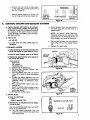
D.
CARBURETOR
ADJUSTMENTS
• The carburetor has been adjusted at the factory for sea level conditions. Adjustment may
become necessary if the unit is used at
significantly higher altitudes or if you notice
any of .the following conditions:
CHOKE CLOSED
HIGH SPEED
MIX SCREW
--Chainmoves
with the engine at idle speed.
.--Loss of cutting power which is not cor.
retted by air filter or muffler screen cleaning.
--Engine dies or hesitates when it should
accelerate.
IDLE SPEED
SCREW
• Permanent damage will occur to the engine if
incorrect carburetor adjustments are made. To
make the adjustment observe the following procedure very carefully,
LOW SPEED
MiX SCREW
Figure 51
2. IDLE SPEED ADJUSTMENT--I
a. -Start the engine.
b. Adjust if the engine stops (when the trigger
is not squeezed) by turning the Idle Speed
Screw 1/2 turn clockwise
The chain may be moving during this procedure.
Wear your protective gear and observe all safety
WARNINGI
precautions.
•
NOTE: To increase idle speed, turn the Idle
Speed Screw clockwise
_
. To
decrease idle speed, turn the Idle Speed_
Screw counterclockwise
_-,=i
• •
I
C.
1. PREPARATION
NOTE: The engine must be at operating
temperature for proper adjustments to be
made.
a, Stop,engine,
b. Use a fresh fuel mixture with proper
gasoline/oil ratio.
c. Place:the saw on a solid, flat surface and
make sure the chain will not contact any
object.
d. Dustoff,the carburetor cover and surround,
ingarea to remove debris which might fall
into the carburetor chamber.
e. Remove the carburetor cover screws and
carburetor cover. Figure 52.
f, Find the three (3) carburetor adjusting
screws. Figure 51,
_
g. Turn the Low Speed Mixture Screw and the
High Speed Mixture Screw clockwise just
until they stop; Do not turn the screws until
they are tight as you may damage the needle seats.
h, Turn the Low Speed Mixture Screw and the
High Speed Mixture Screw one full turn
counterclockwise
Run the engine for a few minutes to bring it
up to operating temperature.
3. LOW SPEED
MIXTURE
ADJUSTMENT
a. Turn the Low Speed Mixture Screw slowly
clockwise
_
until the RPM starts to _
drop. Note the position:
b. Turn the Low Speed Mixture Screw counterclockwise 4[-,,= until the RPM speeds
up and starts to drop again. Note the position.
c. Position the Low Speed Mixture Screw at
the mid-point between the two positions.
4. IDLE SPEED
......
ADJUSTMENT--ll
,_
: a. Ailow engine to idte.
b. Adjust if the chain is turning by'turning the
idle Speed Screw Counterclockwise _
c. Squeeze the throttle trigger;, the saw
should accelerate without hesitating.
;
21
NOTE: It may be necessary to recheck the
low speed mixture setting after the idle
speed has been reduced by repeatingLow
Speed Mixture Adjustment Steps.
5. HIGH SPEED MIXTURE
a. Make a test cut.
ADJUSTMENT
NOTE: Take special care to keep chips and
dirt out of the carburetor.
b. Adjust if the saw smokes or seems to have
low power in the test cut by turning the
High Speed Mixture Screw 1t16th turn
clockwise
c. Repeat test cut.
d.Repeat
adjustment
until the saw ruffs
smoothly.
CAUTION: Never set the H!ghSpeed Mixture Screw less than 718 tumopen. This is
too lean a setting and will rain your engine.
6. IDLE SPEED ADJUSTMENT--Ill
Recheck for proper idle mixture setting.
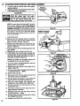
E.
AIR
7. CHECK
ACCELERATION
Adjust if there is a slight hesitation by turning
the Low Speed Mixture Screw 1/16 of a tumat
a time counterclockwise
_
until you
have smooth acceleration.
NOTE: Check to be sure the chain is not turning when engine is idling. If chain moves at
idle speed, repeat Idle Speed Adjustment--II.
8. REASSEMBLE UNIT
a. Stop the engine.
b. Clean the mating surfaces of the carburetor housing and cover.
c. Be careful when replacing the carburetor
cover to see that the choke knob operates
properly. Refer to steps 9 and 10, for "Air
Filter,.this page.
FILTER
• A dirty air filter.
--reduces cuffing power
--increases fuel consumption
• Clean the Air Filter:.
--Frequently, especially
under very dusty
conditions.
--Always after 10 tanks of fuel mixture or 5
hours of operation whichever is less.
:
....
.
•
•L"
....
:
•
_Never
operate the unit without the air
filter in place to avoid engine damage.
.
NOTE: It may be necessary to repeat according to instructions in Steps 2 and 3,
Idle SpeedAdjustmentwl
and Low Speed
Mixture Adjustment.
Clean off the carburetor cover and the area
around it to keep dirt and sawdust from falling into the carburetor chamber when the
cover is removed.
NOTE: Be careful when replacing the carburetor cover as incorrect placement will
prevent the choke from working properly.
9. Move the choke knob all the way to the right.
10. Check the choke shutter to be sure it is
closed. Figure 52.
11. Reinstall the carburetor cover and tighten
the carburetor cover screws.
12. Check the operation of the choke.
NOTE: If the choke knob sticks or will not ....
move, remove the cover and repeat steps
11 and 12 above.
2: Remove the carburetor cover screws and carburetor cover. Figure 52.
3. Pull out the air filter.
4. Wash the filter in soap and water.
CARBURETOR
SCREW
CARBURETOR
COVER
AIR
FILTER
lCAUTION:IDo not use gasoline or other flammable liquid to clean the filter to avoid creating a_re
hazard.
5. Squeeze the filter dry.
6. Add a small amount of oilto
coat the filter.
NOTE: Avoid soaking the filter with oil.
7. Squeeze out excess oil.
8. Replace filter by tucking in edges and
smoothing it flush with the carburetor housing.
22
Figure52
F.
STORAGE
When your saw is to be stored for over 30 days,
always:
1. Drain fuel tank in a safe manner. (See
"Important
Points," page8 .)
2. Start engine and allow to run at an idle
speed until the engine stops.
NOTE: This will remove most of the fuel from
the fuel system.
ICAUTION:j Wear protective gloves when handling the chainL The chain is sharp and can
cut you even when it is not moving.
MAINTENANCE
3.
4.
5.
6.
7.
8.
Drain oil tank.
Remove, clean, and dry the bar and chain.
Store the chain in a container filled with oil
to prevent rust.
Apply a coating of oil to the entire surface of
the bar and wrap it in heavy paper, cloth or
plastic.
Clean the outside surfaces of the engine.
Store the saw in adryplace, out of the reach
of children, and:awayfrom where fuel vapors
can reach open flames from hot water heater,
furnaces, etc.
ACCESSORIES
Available from your nearest
Sears Store, Catalog Sales Office, or Service Center,
but not furnished with your saw.
2
5
Key
No.
1
2
3
4
5
6
Part
No.
STD360946
31059
55004
55O46
51242
51234
Catalog
No.
71-36403
71-36524
71-36565
71-36557
71-3629
71-3631
69037
30113
44247
71-36621
71-36555
71-36554
71-36366
Descdption
Spark Plug-Champion CJ-8
Spark Plug Wrench
File (5/32" alia.)Twin Pack
FileGuide
Depth Gauge Tool
xtra GUARD ®Chain (358.355060--2.3/16"}
Power Sharp®Chain (358.355070-2.3/16"P.S.)incl. Stone and Carder Ass'y.
Muffler Heat Shield Kit
Replacement Recoil Cord
Carrying Case
2-Cycle Engine Oil
Bar and Chain Lubricant
Guide Bar- Lo-Kick®Replacement
23
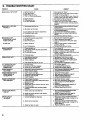
H.
TROUBLE
SHOOTING
CHART
CAUSE
TROUBLE
ENGINE WILL NOT START
+
1.
2.
3.
4.
REMEDY
1. Move switch to "Start".
Ignition Switch off.
Fuel tank empty.
Spark Plug not firing.
Fuel not reaching carburetor;
2. Fill tank with correct fuel mixture, page S-+
3. InStall newplug, page lS.
4. Check for dirty fuel filter;, clean. Check :for
.
kinked or split fuel line; repair or replace.
.
5. See Starting Instructions, page 10.
6. Contact Sears Service Center.
, +
:: .' '
7. Check for dirty air filten clean, page 22; ....
Check for choke shutter working prope!!y,
:
: page 22.
......
+
.
5. Engine flooded.
6. Compression low.
7: Air ftow restricted
ENGINE WILL NOT IDLE
" PROPERLY
1. Idling speed set too low.
+
:
1.
2. Adjust idlespeedscrewcounterclo_wise
to reduce speed, page 21.
.
3. See Carburstor Adjustments, page 21.
4. Replace seats or contact Sears Service
Center.
•5. Contact Sears Service Center.
3. Low speed screw requires adjustment.
4. Crankshaft seals worn ......
.....
•
5. Compression
•
:
low.
+
ENGINE WILL NOT
ACCELERATE, LACKS
POWER OR DIES
tN THE CUT
1. Carburetor requires
2. Air filter dirty.
3. Spark Plug fouted.
4. Carbon
1. See Carburetor Adjustments, page 21.
2. Clean or replace air fitter,page 22.
3. Clean or replace Spark Plug and regap,
page is,
4. Clean exhaust system including spark
arrestor, page 19,
5. Contact Sears Service Center.
adjustment.
build.up.
5. Low Compression.
ENGINE SMOKES
EXCESSIVELY
ENGINE
1.
2-,
3.
4.
Turn Choke off.
See Carburetor Adjustments, page 21,
Clean or replace air filter, page 22.
Empty fuel tank and refill with correct fuel
mixture, pageS,
+
5. Contact
Sears Service Center.
1. Choke partially on.
.. 2. :High speed needle requires adjustment.
3. Air filter dirty.
:,.
4. Oit rich fuel mixture,
5. Crankcase
leak .....
1. Fuel Mixture lncorrecL
2. Spark Plug lncorreCL
3. Carbon build-up.
RUNS HOT
....
1. See Engine Fuel Mixture, PageS- . .........
2- Replace with correct plug, page 19;i!._
3. Clean exhaust systems including spark
arrestor, page 19.
4. See CarburetorAdjustments, page 21.
4. High Speed Mixture set too low.
OIL INADEQUATE FOR
BAR AND CHAIN
LUBRICATION
1. Oil tank empty.
2. Oil pump or oil filter clogged.
3. Guide bar oil hole blocked.
CHAIN MOVES AT
IDLE SPEED
1. Carburetor requires adjustment:
+2. Clutch requires repair_ I +
CHAIN DOES NOT MOVE
WHEN ENGINE IS
ACCELERATED
: CHAINCLATTERSOR +
CUTS ROUGHLY
'
CHAIN STOPS WITHIN
THE CUT
1. Fill oil tank, pa,ge 9.
2. Contact SearsServiceCenter,
3. Remove barandclean,page 18.
+
1. See CarburetorAdjustments,page21.
2. ContactSears ServiceCenter.
1,
Chain tension too tight.
2. Carburetor requires adjustment.
3. Guide bar tails pinched,
'
4. Clutch slipping.
1.
2.
3.
4.
'
1. See Chain Tension, page 7.
2. See Chain Sharpening Instructions,
1. Chain cutter tops not filed flat. .:
1; See Chain Sharpening instnJc'dons,page
16 (page 12for Power Sharp'_);
2. Repair or replace guide bar, page18..
=3. Contact Sears Service Center.
page 17 (page 12 for Power Sharp®)
3. Replace.
4. ResharpenorreplaceChaJn, page6& 18
: (page 12 forPower Sharp®).
5. Contact
Sears Service Center.
.
1. Cutters damaged on one side.
+
'
.:
.
2. Chain dull on one side.
3.
Guide bar bent, or worn.
:::
24
See ChainTension,page7.
See CarburetorAdjuslments,page21.
Repair orreplaoe,page6 & 18.
ContactSears Se_ce Center.
1. Chain tension incorrect.
2. Cutters dull, improperly sharpened; depth
gauges too high.
3. Sprocket worn.
4. Chain wear due to contact with dirt, sand
or frozen wood.
5. Cutters damaged after striking foreign
material.
2_ Guide bar burred or bent; rails uneven.
3. Clutch slipping.
CHAIN CUTS AT
AN ANGLE
Adjust idle speed screw clockwise to increase
speed, page21.
+: • +
2. idle speed set too high.
+,
+
:
::
:
•
+1. Reeharpen until all cutters have equal
angles and lengths, page 17 (page I2 for
Power Sharp ® ).
2. Resharpen until all cutters have equal
::angles and lengths, page 17 (page 12 for
. Power Sharp® ).
3. Replace guide bar, page18.
:.
'
:
:
SEARS CHAIN SAW REPAIR PARTS--MODEL
Figure
NO. 358.355060-2.3/16"AV
1A
Key
No.
1
Part No.
STD541431
2
3
STD511010
12058
Decals
A
B
26472
26224
C
26477
SEARS CHAIN SAW REPAIR PARTS-MODEL
Qty, Description
1
1
1
Nut - Bar Mounting 5116 - 18 Flange
Screw- 10-24 x 7/8
Bar Clamp
1 Decal- Bar Clamp
1 ' Decal - Instructions
(Left Half)
1 Decal - Instructions
(Right Half)
NO. 358.355070-2.3/16"AV
PS
FigurelB
B
Key
No.
1
2
3
4
5
6
7
Part No.
STD541431
23759
23762
23761
STD511010
12061
69027
STD511002
9
69026
Decals
A
B
26472
26224
C
25531
D
26486
Oty. Description
1
1
1
1
!
1
1
Nut - Bar Mounting
-5/16- 18 Flange
Knob Sharpening
Spring
Washer
Screw. 10-24 x 7/8
Bar Clamp
Ass'y_Shatpening Stone Arm
(incl. 9)
Screw- 10-24 x 114
Pan Head
Stone & Carrier Ass'y.
(incl. 8)
1 Decal- Bar Clamp
1 -Decal - Instructions
(Left Half)
1 Decal - Sharpening
Instructions
1 Decal - Instructions
(Right Half)
25
SEARS CHAIN SAW REPAIR PARTS-MODEL
_i_, .... :
tP
NO. 358.355060-2.3/16
AV
=
358.355070-2.3/16"AV
PS
Figure 2
15
48
3
Clutch Drum
and ,Sprocket
for
Model358.355070
6O
6
•26
51
SEARS CHAIN SAW REPAIR PARTS-MODELNO.
....
i
358.355060-2.3/i6"AV
358.355070-2.3/16"AV
PS
Figure 2
PART
NO.
QTY.
1
2
3
STD541408
23492
15236
1
1
1
DESCRIPTION
KEY
NO.
PART
NO.
42
15551.
Lock Nut #8-32
Pin-Bar AdjusL.-.
_ 25689
¢3
Screw-Bar Adjust.
STD551010
8-32 x 1-% RI Hd..
Chain 16"
t 5557
45
358.355060
35B,355070
23535
46
(incl. Stone &,Carder Ass'y.) 47
23796
Bar 16" S.N. ,Guide
10588
,,46_i
Clutch Drum & Bearing
Kit (incL23)
._.
......
15426
49
;355060
'
..
25677
50
.355070
51
Pin-Oil Tank Vent
Stud_.BarMounting
STD511005
52
Crankcase Assembly '
19O88
53
_(incL
1,2,3,7,8,10,11
25876
54
12&20)
24236
55
Check Valve Kit-OilTank
23786
56
Pressure (incl. 12)
STD511007
57
Seat Crankshaft
15499
58
Gasket-Check Valve
Clutch Assembly KR
STD551025
59
(incl. washer}
Clutch Washer Kit
26163
6O
(outside)
23797
61
Screw # 8-32 x 1,_
23794
62
Cover-Oil Pump
23787
63
Gasket-Oil Pump
STD610805
64
Filter Oil
Body Assembly24256
65
Oil Pump
25451
66
Bearing-Crankshaft
15342
67
Crankshaft-Solid State
STD360946
68
Line,Oil Discharge
12065
69
Beadng-Clutch.
15239
7O
Spacer-Clutch(inside)
Be=ing-RoBer
3OO54
71
(incl. 12 bearings)
Thrust Washer31O63
72
Crankshaft
62O23
73
ChaimOll Cap
Retainer-Chain
25675
74
Screw-8-16 x 3/s
15531
75
O-Ring Oil Cap
Cap-Oil
15343
76
Oil Cap Assy.
66378
(incl.27-31)
Screw #10-24 x I xTAs
,Decals
Cover Muffler 25631
A
Retainer-Piston Ring
26545
Washer-Rod (Top)
Bearing Rod (Top), _,
(incl. 22 bearings)
2655O
lOt--Connecting Rod
(incl. 25, 39 &40)
OTY .... DESCRiPTiON
1
1
2.
_r
(EY
_0.
4
5
6
5124251234
1
1
44247
1
_i
'
_
69t66"_
69167
23792
15249
10469
7
8
9
1.
1
1
1
1
10
69142 _ _,: 1
11
.12
13
19o59i
'2
19o89
1
69179
1
14
69165
1
15
16
17
18
19
STD510805
23802
19091
23801
10195
2
1
2
1
1
20
21
,22
23
24
32058
22172
21026
32079
23519
2s
32oss
2
1
1
1
1
1
26
23887
1
27
23653
28
23656
29
30
31
32
STD6_
1949
23874
10221
1
1
1
1
1
1
36
37
38
39
40
STD511015
23795
23843
15486
32075
1
1
2
2
1
41 .
10474
1
Key Nos. Excluded: 33, 34, 35
2
1
1
1
1
2
"i
2
1
1
1
1
7
1
1
4
2
1
1
1
2
1
1
1
1
2
1
1
1
1
1
1
1
1
Screw-Isolator
• (#V4-20 x 23/%
_ Bracket-Lower Isolator
,.Washer Lower Bracket
Mtg. (#10) •
Screw-Bracket Mounting
(10-24 x %) i
Spacer-MufflerCover
•
Screen-SparkArrestor
_ •"
Piston KR
,
(incl. 38, 54 & pin) ,
Bolt-¼-#20 X 1/2
, Bracket-Rear ]solat0r
•Screw-#8-32 x ;'/16
Pan Head
Screw-#10-24 x 1/2.
Gasket-Cylinder
Piston Ring
Knob Ass'y.-Switch
Ramp-Switch
Screw #10-24 x _As
Screw Handlebar
Mtg.-Top (#%-10 x lZ/4)
Washer Handlebar
,Mtg.-Top (#fl/_-Type B)
" Cup-isolator
Baffle-Muffler
Body-Muffler
Clamp-Switch
Screw-#8 x _A_
Tapping
Isolator
Handguard
Spacer
Spark Plug-CJ-8
Cylinder
Screw-%-20 x 3/4
Socket
Seata_-Orankcase
(Optiona!)
Bar Adjusting Tool
Chain Repair IO
(358.355060 only)-optional
Handlebar w/Insert
_Washer-Handlebar
Lower (V_)
Spacer
Operator's Manual
(notshown)
Dec_al-Handguard
Decal - Warranty(Guide Bar)
(not shown)
Decal - Chain TensioningNot Shown
27
SEARS CHAIN SAW REPAIR PARTS-MODEL
_
NO. 358.355060-2.3/16"AV
358.355070-2.3/16"AV
PS
Rgure3
2O
21
" 60 _
13
.....
26
•
r 15
17
I
23
30
15
I
28
58
66
SEARS CHAIN SAW REPAIR PARTS-MODEL
NO. 358.355060-2.3/16"
358.355070-2.3/16"
CVA
CVA PS
Figure 3
,EY
_10.
PART
NO.
1
2
15126
39it I
"
3
4
5
6
3933
24158
39087
QTY.
1
1
I
1
1
1
2
1
1
2
1
1
1
STD510807
2._1
25676
15t'68
15157
238O6
STD600603
14
39082 -
15
16
17
18
23817
STD541131
15127
1648
19
15524
1
2O
21
22
23
24
25
26
27
28
29
3O
31
32
33
25679
24317
STD511005
15428
10373
42023
35181
23791
STD512507
25487
1
1
1
1
1
1
1
1
3
1
2
1
1
2
Key-Flywheel
Flywheel Assembly
(incL 15)
Boot-Spark Plug
Connector-Spark Plug
Lead-Sw'r_ch
Module-Ignition
(incL 14)
Screw #8-32 × 3/=Seres
Knob-Choke "
Cover-Carburetor
Screw-# 10-24 × -%
Wave'Washer
Lever-Choke
Screw-#8-16 x _'e
Tapping
Ass'y Lead Spark Plug
(incL #3 & 4)
Spring-Starter Dog
Nut-SAs-24
Washer-Flywheel
Screw-l/4-20 × 1¼
Hex Head
Screw-Isolator
(#¼-20 x 1_1A6)
Bracket-Upper isolator
Pad-Isolator
Screw-#10 x 24 x _/_
Washer
Pulley Starter (incl. 23)
Spring-Starter
Carburetor-WT-20
Air Filter
Screw-¼-20 x _1A_
Baffle-Air Intake
Screw-Baffle
Fan Housing
Spacer
- :,
Cuplsolator _,
r
7
8
9
10
11
12
13
DESCRIPTION
STD600803
12O60
15342
26163
1
2
1
1
1 "
KEY
NO.
PART
NO.
34
35 ,
:36 '
37
38
9
40
_, •
,
•41
42
: 43
.•44
4-5
46
47
48
49
50
51
52
53
54
QTY.
24256
.15245
23865
1
2
1
23805
15254
25978
19117
1
1
1
1
23366 .......
23367 "
STD6i0603
21035 ....
1
1
1
56
57
23373
19045
15252
23364
23363
15528
25683
23808
23783
' 19093
25143
25685
15406
58
59
STD541425
2
1
60
61
25686
25687
1
1
62
15533
1
63
64
65
66
25682
25684
25681
15495
1
1
1
2
;55
1
1 "
1
1
1 '
1
t
1
1
1
1
1
1
15z
DESCRIPTION
Isolator
Screw-#10-24#1%
Spacer-Choke
Shutter
Shutter-Choke
Wave Washer
Housing-Carburetor
Gasket-Carburetor
Housing
.Reed ,Valve
.Washer-Reed Valve
Screw-#6 x sA6
Tapping
Fuel Line (Bulk no.
8133)
Boot-Throttle Wire
Gasket-Carburetor
Washer-Fuel Pick-up
Filter-Fuel
Weight-Fuel Pick-up
Washer-Trigger (nylon)
Trigger-Throttle
Fuel-Cap Ass'y.
Rope & Handle Starter
Sea!-Fuel Tank Neck
Fuel Tank
W_re-ThrotUe
Screw-#10-24 × _/2
Slotted Pan Head
Screw-#10-24 ×3/s
Locknut-Handlebar Mtg.
(#,,_-2o)
Spring-Trigger
SpringThrottle
Lockout Lever
: Screw-Rear Handle-Front
(#10-16 x 1'/_)
Rear Handle-Right
Lever-Throttle Lockout
Rear Handle-Left
Screw, Rear Handle
(#1o-16 x 3/:,)
Decals
A
26473
:
1
'Decat.Fan Housing
29
SEARS CHAIN SAW REPAIR PARTS-MODEL
_
=
NO. 358.355060-2.3/16"AV
358.355070-2.3/16"AV
PS
Figure4
9-O
26
27
KEY
NO.
1
2
3
4
5
6
7
8
9
10
11
12
13 •
14
15
30
=
PARr
NO.
350O6
35015
35034
35024
35171
35023
35169
35167
35162
35163
35017
35159
35O35
35168
35164
DESCRIPTION
Valve Throttle
Screw-Throttle Valve
Shaft Assembty-Throttle
Spring-Throttle Return
Needle-Low Speed Mixture
Spring.Low Speed Mixture Needle
Needle-High Speed Mixture
Spring-High Speed Mixture Needle
"Plug 5/16 Dia. Welch
*Plug 1/4 DiaoWelch
Screw-Pump Cover
Cover-Fuel Pump
Screw-Idle Speed Adjusting
Spring-Idle Speed AdjustingScrew
+ *Gasket-Fuel Pump
KEY
NO.
16
17
18
19
20
21
22
23
24
25
26
27
PART
NO.
35166
35027
35007
35O08
35188
35031
35O28
35016
35165
35014
35003
35021
35161
35173
DESCRIPTION
+*Diaphragm-Fuel Pump
Screen-Fuel Inlet
Ring-Throttle Retainer
*Valve-inlet Needle
*Spring--Metering Lever
*Lever-Metering
*Pin-Metering Lever
"Screw-Metering Lever Pin
+"Gasket-Metering Diaphragm
+'Diaphragm-Metering
Cover--Metering Diaphragm
Screw Assembly-Metering Cover
Kit-Repair (includes parts marked*)
Kit--Gasket!Diaphragm (includesparts
marked+)
•
Read
QUICK REFERENCE PAGE
and follow
aft Safety
Failure
Rules,
to do so can
Precautions
result
and Operating
in serious
personal
Instructions.
injury.
page
SAFETY
RULES
AND
PRECAUTIONS
..................
. ......
PREPARATION
1..
2.
3.
4.
5=
........
.............
3-4
_
3
Wear:personal
protective gear
gloves; safety footwear;
appropriate eye, hearing and head protection.
Check saw for worn, loose, or damaged parts and repair or
Check',the chain for sharpnessand
tension.
Keep children, bystanders and pets out of the work area.
Plan your sawing operation carefully in advance.
snug fitting clothing; and
-_ •
replace if necessary.
'
-,.
-:
.
....
FUEL AND OIL .................
1.
2.
3.
4.
5.
6.
8-9
Eliminate all .sources of sparks or flame where fuel is mixed, poured, or stored.
Use I part air-cooled, 2-cycle engine .oil to 16 parts-regular gasoline.
'
Use gasoline not over 2 months old.
:
:_
•
'
,
Mix, store and pour fuel in an approved, marked container and in a well-ventilated area.
Move a minimum of 10 feet away from fuel and fueling site before starting engine.
Fill the oil tank each time the.fuel tank is refueled.
STARTING THE ENGINE.'
1.
2.
.3.
4.
5.
....
5.
6.
.
.....
.
11
Cut wood only.
.•
Accelerate the engine to full throttle before entering the cut.
Begin cutting with the saw frame up against the tog.
Cut only at full throttle.
Release the trigger as soon as the cut is completed.
Stop the engine before setting thesaw down after cutting.
MAINTENANCE
1.
2.
3.
4.
lo
Hold saw firmly with the saw chain free to turn without making contact with any object.
"
Push saw away from you with your right hand while pulling tl_e starter rope with your left hand.
Use no more than 15-18 inches of rope per pull .....
. ....
Pull rope no more than 5.6 times.
Release the trigger after, engine starts allowing engine to idle.
OPERATING THE SAW ......
1.
2.
3.
4.
5.
6.
'
............
,....,
........
. .. ..........
. ...........................
17
Adjust Or have the carburetoradjusted
if thechain moves when the engine idles.
Disconnect spark plug before'performing
maintenance except for'carburetor adjustment.
Check the guide bar for weareach:timel the chain!is sharpened. ' i ':
.
Clean the air filter:frequentlyand
always afterl0tanksof
fuel mixture or5 hours of operation,
whichever isless.i:
......
_ . • "
:i:
:::: :
: ::::i'i
::
Clean ,igniton, cooling and.exhauSt systems at_teast onceforeach
_
hours of operation.
Drain =fueltank in asafemanneraftereach
use=:I
_:: ::: : :' :': :: :: :
in a dry p!aceout of the: reachof children, ::
;
:: :
::
:2
WATCH OUT FOR
I
........
I
THE SAWWHEN
\
l
I ' NEVER USETHE
l
SAW
WHEN TIRED
:
I
!....
"
USEA FIRM GRIP
"
BOTH
HANDS
.....31.
_-The Model Number will be found under the handle with the Serial
Number. Always mention the Model Number when requesting service or repair parts for your Chain Saw.
All parts listed herein may be ordered from any Sears Service Center
and most Sears Stores.
WHEN
ORDERING
REPAIR
PARTS,
FOLLOWING INFORMATION
AS SHOWN
1.
The PART NUMBER
3.
2.
The MODEL NUMBER
4.-,The
358.355060-2.3/16"AV
358.355070-2.3/16"AV
MODEL NO.
NAME OF ITEM --
Chain Saw
PS
When you
from Sears
something
can offer ...
358.355070
2.3/16"AV PS
THE
The PART DESCRIPTION
if the parts you need.are not stocked locally,
electronically
transmitted
to a Sears Repair
center for expedited handling.
358.3550602.3/16"AV
your order will be
Parts Distribution
buy merchandise
you get an extra
that nobody else
SearsService.
Across town or across the
country, Sears Service follows
you, providing
trustworthy,
competent service technicians
using only Sears specified
factory parts.
How to Order
Repair
ALWAYS
GIVE
1N THIS LIST.
Parts
SEARS SERVICE
• Sears,
Roebuck
and
Co.,Chicago,
Ill. 60684
U.S.A.
PRINTED IN U.SJL
66378-I -12084-2-17884