1
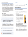
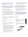
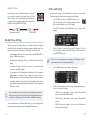
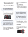
Workshop ®ÂØÒňΠ® VB-99 V-Bass System Pickup Settings © 2009 Roland Corporation U.S. All rights reserved. No part of this publication may be reproduced in any form without the written permission of Roland Corporation U.S. The trademarks listed in this document are trademarks of their respective owners, which are separate companies from Roland. Those companies are not affiliated with Roland and have not licensed or authorized Roland’s VB-99. Their marks are used solely to identify the equipment whose sound is simulated by Roland’s VB-99. VB99WS02 1 About the Workshop Booklets Roland’s VB-99 V-Bass System is, simply put, the most powerful bass processor ever made. It’s the second-generation V-Bass system from Roland, and it offers an unprecedented set of creative sound-making tools for the bassist. Featuring dual COSM bass and amp modeling paths, two independent multi-effects processors, massive realtime control options, pitch-to-MIDI conversion, and USB, the VB-99 is a bassist’s dream machine, capable of producing sounds that are limited only by your imagination. Each VB-99 Workshop booklet focuses on one VB-99 topic, and is intended as a companion to the VB-99 Owner’s Manual. About This Booklet This booklet discusses setting up the VB-99 for use with a divided pickup such as the Roland GK-3B or a piezo system. Connecting your bass’ normal pickup output to the VB-99 is covered as well. The trademarks listed in this document are trademarks of their respective owners, which are separate companies from Roland. Those companies are not affiliated with Roland and have not licensed or authorized Roland’s VB-99. Their marks are used solely to identify the equipment whose sound is simulated by Roland’s VB-99. Hot Links Each Workshop booklet is meant to be read in order from beginning to end. However, if we mention an upcoming section—and you see this arrow—you can click the arrow to jump there immediately. About Pickups and the VB-99 Using a Divided Pickup with the VB-99 To use the VB-99’s COSM instrument modeling—along with its related features such as alternate tunings and Poly FX—and Bass to MIDI function, you’ll need a bass with a “divided” pickup and a 13-pin output jack. This could be a bass with: • a Roland GK-3B pickup (or similar)—The GK-3B is a user-installable divided pickup and control unit that can be easily mounted on most electric basses with no modifications necessary. The pickup works with basses that have four, five, or six strings, and the installation kit comes with everything needed to mount the pickup and the accompanying control unit. (Roland’s earlier generation GK-2B divided pickup can be used with the VB-99, too.) Understanding the Symbols in This Booklet • a permanently installed GK pickup and Throughout this booklet, you’ll come across information that deserves special attention—that’s the reason it’s labeled with one of the following symbols. • a piezo-type divided pickup system—With this setup, the normal bridge A note is something that adds information about the topic at hand. A tip offers suggestions for using the feature being discussed. controls—such as a bass that’s had a Roland GK-KIT-BG Divided Bass Pickup Kit installed. Bass with a Roland GK-3B Divided Pickup installed saddles are replaced with special saddles, each incorporating its own piezo-type (pressure sensitive) pickup. Each pickup has its own separate output, which is fed first to a preamp unit and then to a 13-pin jack. Piezo-type divided pickup systems are available from pickup manufacturers such as RMC and Graph Tech Guitar Labs. Instrument manufacturers such as Brian Moore, Godin, and others offer basses with this type of pickup system factory installed. Warnings contain important information that can help you avoid possible damage to your equipment, your data, or yourself. 2 A divided pickup is also sometimes called a “hex,” “hexaphonic,” or “polyphonic” pickup. See the VB-99 Workshop booklet Introduction to the VB-99 for more information on the benefits of using a divided pickup with the VB-99. Using Regular Bass Pickups with the VB-99 You can use the output from a regular electric or acoustic-electric bass—or any other electronic instrument for that matter—with the VB-99. Just plug its output into the VB-99’s rear-panel 1/4-inch BASS INPUT jack. You won’t be able to use COSM instrument modeling and its related features or the Bass to MIDI function; those require a divided pickup. However, you can use all the rest of the VB-99’s processing options, including COSM amps and effects. • By plugging in the divided and normal pickups separately—Plug the divided pickup’s output into the 13-pin GK INPUT jack and the bass’ regular output into the VB-99’s BASS INPUT jack. When a plug is connected to the BASS INPUT jack, it overrides the normal bass signal that arrives at the 13-pin connector. When you wish to blend the divided and normal pickup sounds, you should set the GK CONNECT setting to AUTO or ON. This is discussed in the “GK Connect” section near the end of this booklet. The COSM BASS section in the VB-99 provides controls to adjust the levels of the modeled sound(s) and the normal pickup sound as desired in each patch. To learn more, see the VB-99 Owner’s Manual. Plugging In When using only the BASS INPUT, you should set the GK CONNECT setting to AUTO or OFF. This is discussed further in the “GK Connect” section near the end of this booklet. Divided Pickup Blending the Signal from a Divided Pickup and a Regular Pickup Using a Roland-compatible 13-pin cable (such as the one included with the VB-99), plug one end into the 13-pin jack on your bass and the other end into the GK IN jack on the VB-99’s front panel. The VB-99 allows you to combine and blend the signals from a divided pickup and the regular pickups on your bass. Combining signals can be accomplished one of two ways: • By sending the output of your regular bass down the 13-pin cable along with the divided pickup signal—When using a Roland GK-3B or GK-2B pickup, you can plug a short cable (included with the pickup) from the output jack on your bass into the GK control unit. (See the image on the previous page.) The control unit has a switch that allows you to select the divided pickup, regular pickup, or a mix of the two. The 13-pin cable supplied with your VB-99 may have a ferrite sleeve attached at one end. If so, plug this end into the VB-99’s GK IN jack. To 13-pin jack on bass To VB-99 GK IN Ferrite sleeve If you have a bass with a GK or piezo divided pickup system built in, it will usually be configured to send the normal bass sound through the 13-pin cable along with the divided pickup sound. 3 Editing a GK Setting Regular Pickup If you want to use your normal bass pickups—and you’re not sending the normal pickup signal along the 13-pin cable—plug one end of a standard instrument cable into your bass’ regular output jack, and plug the other end into the VB-99’s rear-panel BASS INPUT jack. To the output jack on the bass You may need to make some measurements on your bass for some of the following settings, so have a metric measurement tool handy. 1 Press SYSTEM, and then use the PAGE buttons to go to Page 1 in the display. (The current page number is shown in the upper right-hand corner of the display.) 2 Press F3 (GK), and then use the PAGE buttons to go to Page 1 in the display. 3 Use the F4 knob or button to choose the GK Setting (1-10) you’d like to edit. (The currently selected GK Setting is shown at the top of every GK SETTING screen.) To VB-99 BASS INPUT Divided Pickup Settings When using a divided pickup, there are a number of VB-99 parameters that must be set to optimize the pickup’s performance with the unit. These parameters are stored collectively as a “GK Setting,” and they include: • the pickup type that’s used—You can choose from the GK-3B, GK-2B, or a variety of different piezo types. • the instrument’s scale length—That is, the distance from the nut to the bridge. • the number of strings on the bass—Four, five, or six, and how they correlate to an installed pickup. There is no “save” procedure when working with GK Settings. All the adjustments you make are saved automatically. 4 Use the PAGE buttons to go to Page 2 in the display. 5 Use the F1 knob or button to select the type of divided pickup in your bass. Select from the following: • the orientation of the GK pickup and the distance from the instrument’s bridge saddles to the pickup—These settings are only necessary for GK-type pickups, as piezo-type pickups are built into the bass saddles. • the picking sensitivity for each string—This setting balances the volume from string to string, and optimizes the input gain of each string for the VB-99’s processing. Be sure to take the time to make accurate divided pickup settings— they have a very big impact on the VB-99’s sound and performance, and are critical to achieving sonic nirvana with its modeled instruments. • GK-3B—Choose this setting if you’re using a Roland GK-3B pickup or have a GK-KIT-BG installed. • GK-2B—Choose this setting if you’re using a Roland GK-2B pickup. You can edit and name 10 different GK Settings, so you can quickly call up the unique divided pickup settings for multiple different basses. • PIEZO—Choose this setting if your bass has a flat-response piezo-type divided pickup. 4 • PIEZO G—Choose this setting if your bass is equipped with a There are also a few short cut settings for the scale lengths of popular instruments: piezo-type divided pickup manufactured by Graph Tech Guitar Labs. • SHORT—which is equivalent to 760 mm. • PIEZO R—Choose this setting if your bass is equipped with a • MEDIUM—which is equivalent to 812 mm. piezo-type divided pickup manufactured by the RMC Pickup Co. (such as the Brian Moore iBass). • LONG JB/PB—which equivalent to 864 mm. This is the scale length of the Fender Jazz Bass and Precision Bass, and many other popular basses as well. This setting can be quickly called up by pressing the F4 button. If your bass is equipped with a piezo-type divided pickup but you’re not sure of the manufacturer, try out the different piezo settings as you play, and then choose the one that has the most natural sound. 6 If you’ve chosen a piezo-type in Step 5, you can adjust the high and low frequency tonality of the pickup’s sound. To do so, use the F2 and F3 knobs to adjust the LOW and HIGH sound parameters. Values in the “+” range boost the selected frequency, while “-” values cut it. The goal is to adjust the LOW and HIGH parameters to achieve the most natural sound before the piezo pickup is processed by the VB-99’s modeling and effects. You can do far more dramatic tonal adjustments later using the VB-99’s various patch and global EQ controls. To start, we’d recommend leaving the LOW and HIGH parameters at 0. After working with VB-99’s processing a bit, you can always go back and tweak them later if you feel it’s necessary. 7 Turn the F4 knob to set the scale length to match that of your bass. The available range is 710-940 mm. In the unlikely event that the scale of your instrument is outside the available range, set BASS SCALE to the setting that’s the closest. • EXTRA LONG—which is equivalent to 914 mm. If you’re unsure of the scale length of your bass, here’s how to determine it: use a ruler or tape measure to measure down the center of the fingerboard from the leading edge of the nut—where the strings pass over from the fingerboard to the headstock—to the center of the 12th fret. (If you have fretless bass without fret markers, measure to the position where you can play an octave harmonic half-way up the string’s length.) Then, double this measurement and you’ll have the scale length. If you don’t have a measurement device handy, you should be able to get the scale length information from the instrument’s manufacturer. 8 Use the F5 knob or button to choose the string orientation of your bass strings in relation to the installed pickup. This is called the GK Pickup Position (GK PU POS) setting. The available options cover four-, five-, and six-string basses. This setting affects how the VB-99 processes signals from the divided pickup, and also how strings are displayed in the built-in tuner. As you change the setting with the F5 knob/button, the image in the right side of the display changes to give a visual indication of the string orientation and compliment. Choose the setting that matches your instrument. 5 When the GK PU TYPE is set to GK-3B or GK-2B (Step 5), the GK PU POS setting should mirror how the pickup is physically installed on your bass in relation to the strings. The available settings are shown below. When the GK PU TYPE is set for a piezo-type divided pickup (Step 5), the different GK PU POS settings are for how the saddles are physically wired to the 13-pin jack in your particular instrument. If you have a four- or five-string bass, play all the strings as you try out the different settings to find the right one. If you have a six-string bass, simply choose the “6STR” setting. 4STR-3 4STR-2 4STR-1 String 1 (G) String 2 (D) String 3 (A) String 4 (E) Now, if you’ve selected GK-3B or GK-2B as the pickup type in Step 5, go ahead to Step 9. If you’ve selected a piezo-type pickup, skip ahead to Step 12. GK PU POS: Four-string bass settings 5STR Lo1 5STR Lo2 String 1 (G) String 2 (D) String 3 (A) String 4 (E) String Lo (B) 5STR Hi1 String Hi (C) String 1 (G) String 2 (D) String 3 (A) String 4 (E) GK PU POS: Five-string bass settings 6STR String Hi (C) String 1 (G) String 2 (D) String 3 (A) String 4 (E) String Lo (B) GK PU POS: Six-string bass setting 5STR Hi2 9 Use the PAGE buttons to go to Page 3 in the display. 10 Use the F2 button to choose the GK-3B/GK-2B pickup’s direction. If the GK pickup is installed so that the cable exits the pickup towards the bridge, select NORMAL. If the cable exits the pickup towards the neck, select REVRSE. 11 Use the F1 button choose the GK-3B/GK-2B pickup’s phase. If the GK pickup is installed so that the cable exits the pickup towards the bridge, select NORMAL. If the cable exits the pickup towards the neck, select REVRSE. The phase setting adjusts the divided pickup’s phase in relation with your bass’ normal pickups. If the sound is thin or “hollow” when you blend your normal bass pickup(s) with a COSM instrument sound, try the alternate GK PU PHASE setting to see if that alleviates the problem. When the divided pickup sound is played by itself, the GK PU PHASE setting will have no audible effect. 6 12 Roland’s GK-3B and GK-2B divided pickups—as well as most non-Roland divided pickup systems—have two onboard switches for controlling various VB-99 functions remotely from the bass. The S1,S2 POS setting allows you to reverse the control functions assigned to them if you wish. Press the F3 button to choose the desired setting: NORMAL or REVRSE. 13 If you’ve selected GK-3B or GK-2B in Step 5, use the PAGE buttons to go to Page 4 in the display. If not, skip ahead to Step 15. 15 On Page 5 in the display, the sensitivity meters for the bass strings are displayed according to the setting you made in Step 8. As such, your display may look a little different than what’s shown here. 16 On Page 4 in the display, the bass strings are displayed according to the setting you made in Step 8. As such, your display may look a little different than what’s shown above. 14 Use the PAGE buttons to go to Page 5 in the display. Set the input sensitivity for each string. Begin by playing the bass’ first string in open position (unfretted) at the maximum force that you’d normally play at. Watch the meter in the display, and adjust the F1 knob so that the meter registers just short of its highest level at the maximum playing force. Then, play the other strings in open position one at a time and use the appropriate F knobs to enter the sensitivity settings for each. Use the F knobs to set the distance from the GK pickup to each string’s saddle (“1st” indicates the bass’ high “G” string). To determine the distance, use your measurement tool to measure from the back edge of the GK pickup to the point where each string passes over its saddle. GK pickup Saddle The saddles on most electric basses are movable, allowing each string’s length to be adjusted slightly so that it plays in tune up and down the neck. This procedure is called “adjusting the intonation,” and it’s typically part of a standard bass setup when your instrument is serviced by a repair technician. If you have the intonation adjusted any time after making the settings in Step 14, make sure you revisit those settings and adjust them if necessary. If you have a four- or five-string bass with piezo-type pickups and the string sensitivity meters shown in the display don’t match the strings you’re playing on your bass, go back to Step 8 and try an alternate setting. Then, come back to Step 16 to see if the problem has been remedied. If not, repeat the procedure until you find the Step 8 setting that’s correct. 17 That’s it—press EXIT twice to return to the Play screen, or move on to the next section to name the GK Setting. 7 The Play screen is the VB-99’s “home” screen. It’s the screen that’s displayed after the VB-99 finishes its power-up sequence. You’ll usually want to return to the Play screen when you’re done editing any VB-99 functions. Naming a GK Setting You can name GK Settings to keep track of settings for the different basses you use with the VB-99. 1 Use Steps 1-3 in the previous procedure to navigate to Page 1 of the GK SETTING screens. (If you’re still in another GK SETTING screen, simply use the PAGE buttons to navigate to Page 1.) 2 Use the F4 knob or button to choose the GK Setting (1-10) you’d like to name. 3 Press F6 (NAME). Selecting a GK Setting To select a GK Setting you’ve edited for a particular bass: 1 Navigate to Page 1 of the GK SETTING screens (see Steps 1-2 in “Editing a GK Setting”). 2 Turn the F4 knob to select the desired GK Setting. (Alternately, you can scroll through the GK Settings by repeatedly pressing the F4 button.) 3 Press EXIT twice to return to the Play screen. If desired, you can store specific GK Settings in VB-99 patches. This allows you to create patches for use with different basses, and automatically switch the GK Setting without having to navigate to the GK SETTING screen. We’ll show you how in the next section. Other Divided Pickup Settings The following are global settings for any bass connected to the VB-99’s GK IN. To adjust these settings, first navigate to Page 1 of the GK SETTING screens (see Steps 1-2 in “Editing a GK Setting”). 4 Enter the desired name for your GK preset: • To select a character—use the PATCH/VALUE dial. • To change to a different character position—use the PAGE buttons. • To insert or delete a character, or enter a blank space—use the F1-F3 buttons. • To change the selected character’s type—use the F4 button. • To change the selected character’s case—use the F5 button. 5 When you’re finished, press the EXIT button three times to return to the Play screen. GK Connect This setting determines whether the VB-99’s GK IN jack is turned on, off, or switched automatically when a cable is plugged in. Use the F1 knob or button to choose the desired setting: • OFF—This disables the GK IN jack, and enables the rear-panel BASS INPUT jack. Use this setting when you’re only using the VB-99 with a bass with regular pickups that’s connected to the BASS INPUT jack. • ON—This enables the GK IN jack. Use this setting when you’re only using the VB-99 with a bass with a divided pickup. 8 • AUTO—With this setting, the VB-99 automatically detects whether a 13-pin pin cable is connected to the GK IN jack, and adjusts the GK Connect accordingly. Use this setting if you alternate using a bass with divided pickups and a bass with regular pickups, or if you’re using both jacks simultaneously. GK Setting Mode Use this to choose whether the GK Setting is set globally for all patches, or selected on a patch-by-patch basis. Use the F3 knob or button to choose the desired setting: • SYSTEM—When this is selected, all VB-99 patches use the GK Setting currently selected on the GK SETTING screen. Use this setting when you’re using a single divided pickup bass with the VB-99, or when you want to manually switch settings for different basses. • PATCH—When this is selected, the GK Setting is determined by that chosen in the currently selected patch. Use this setting when you want to create different patches for use with specific GK-equipped basses. Saving a GK Setting in a Patch Saving a patch overwrites the data in the selected destination patch. If the destination patch contains data you want to keep, select a different patch, or back up its data to a computer via USB before proceeding. To learn more about working with patches, see the VB-99 Owner’s Manual or the VB-99 Workshop booklet Working with Patches. 1 Set the GK Setting Mode to PATCH, as described above. 2 Select the desired patch. 3 Using the procedure described in “Selecting a GK Setting,” choose the desired GK Setting. 4 Press WRITE, choose the desired user patch location with the PATCH/VALUE dial, and then press WRITE again. If you change the GK Setting Mode back to SYSTEM, the GK Settings stored in patches are ignored, and the GK Setting currently selected on Page 1 of the GK SETTING screens is used by all patches. GK Volume and Switch Functions Roland’s GK-3B, GK-KIT-BG, and GK-2B pickups—as well as most Roland-ready basses and third-party divided pickup systems—have a control knob and two onboard switches that allow you to control various VB-99 parameters directly from your bass. On the GK-3B/GK-2B, the control knob is called “GK VOL,” while the switches are labeled “DOWN/S1” and “UP/S2.” The “DOWN” and “UP” designations on the switches refer to when you assign them to adjust a directional function, such as scrolling through patches or adjusting the patch level. When making assignments to them in the VB-99, the switches are simply called “GK S1” and “GK S2.” On a bass with a non-Roland divided pickup, the knob and switches may be labeled differently, with names such as “synth volume” for the control knob and “program up” and “program down” for the switches. From Page 1 of the GK SETTING screens, press F2 to select the GK FUNC screen. Here, you can select VB-99 parameters that are controlled by the GK VOL knob and S1/S2 switches. 9 1 Turn the F1 knob or press the F1 button to set the desired GK VOL behavior. Turn the F6 knob or press the F6 button to set the desired S1 and S2 switch behavior. • OFF—This setting disables the GK VOL knob or S1/S2 switches. • ASSIGNABLE (PATCH)—With this setting, the parameter (or parameters) controlled are determined by settings made in each patch. • A specific parameter—When a specific parameter is chosen, it’s used globally by all patches. 2 Press EXIT three times to return to the Play screen. For a listing of all parameters that can be assigned to the GK VOL knob and S1/S2 switches, see the VB-99 Owner’s Manual. The control orientation of the S1/S2 switches is affected by the setting made in Step 12 of “Editing a GK Setting.” The End We hope you’ve found this workshop helpful. Keep an eye out for other VB-99 Workshop booklets available for downloading at www.RolandUS.com. 10