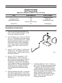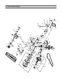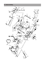
1
TO OUR CUSTOMER:
Thank you for purchasing an EverRide Wasp Walk Behind Mower. We believe that
you have exercised excellent judgment in your selection. The Wasp has been designed to
give you many years of satisfactory service. Successful operation and long life depends
on proper maintenance and correct operating techniques.
Before you received your unit, the dealer has performed a pre-delivery inspection.
The dealer will discuss with you the features, operation and maintenance requirements.
Your dealer will always be there to help you any time you need assistance or need
equipment related to the use of your EverRide mower.
We recommend that you carefully read this entire manual before operating the unit.
This operator’s manual has been printed to provide you with safe operating techniques,
proper maintenance procedures, correct assembly, and parts identification on your
EverRideWalk Behind Mower. Keep this manual handy for future reference.
Should any assistance be needed in understanding any section of this manual,
contact your EverRide products dealer.
EverRide reserves the right to make changes or add improvements to its products without incurring
any obligation to make such changes to products manufactured previously. EverRide, or its dealers,
accept no responsibility for variations which may be evident in the actual specifications of its products
and the statements and descriptions contained in the publication.
© 2005
Auburn Consolidated
Industries, Inc.
OWNER’S WARRANTY INFORMATION
This warranty applies to the original retail purchaser of the
EverRide products only. The warranty period starts upon the
date of the original purchase reflected on the sales invoice.
As a condition to this warranty, the owner/operator shall
have read, understood and followed the operator’s manual
guidelines for operations and maintenance supplied with this
product, and that the product registration shall have been
mailed to EverRide. Any lack of good maintenance, such as
maintaining proper belt tension, tire pressures and lubrication shall be reason for rejection of a warranty claim.
In the judgment of EverRide, any original part found to be
defective in material, workmanship or performance, will be
repaired or replaced with a new part only by an EverRide Authorized Servicing Dealer without charge for parts and labor
based on the following terms and conditions:
Warranty Coverage:
This warranty is limited to two years from the date of purchase for parts and one year for labor for any EverRide
product used for commercial purposes, income producing
purposes or residential use. EverRide products used for
rental purposes are limited to 90 days of warranty. Engine
and battery warranties are provided separately by the manufacturer of those components.
Belts, cutting blades, grass collection bags and tires are
guaranteed to be free from manufacturer’s defects for the
first 90 days.
The mower deck shell will be warranted from cracking as
a result of defects in material or workmanship for the life of
the unit.
Service parts are warranted for 90 days from the date of
purchase.
What this warranty does not cover:
Damages that are caused by unauthorized attachments, alterations or modifications will not be covered under warranty.
Any piece of equipment where the serial number has been
removed or is made illegible will not be covered under warranty.
Wear or maintenance items (unless defective) including, but
not limited to: Clutch and brake linings, light bulbs, grass
bags, filters (air, fuel, oil), lubricants & coolants (unless used
during an authorized repair), spark plugs, injector nozzles.
As the manufacturer of this product, EverRide reserves the
right to change, modify or improve the design of any of its
products without assuming any obligation to modify or upgrade any mower, previously sold or manufactured.
As stated above, all other implied warranties are limited in
duration. Any such implied warranties including merchantability, fitness for a particular purpose, or otherwise, are disclaimed in their entirety after the expiration of the warranty
period. EverRide’s obligation to the original owner is strictly
and exclusively limited to the repair or replacement of defective parts, and EverRide does not assume nor authorize
anyone to assume for them any other obligation.
EverRide assumes no responsibility for incidental, consequential or other damages including, but not limited to:
Transportation of the mower to an Authorized Dealer and
returning it back, rental of truck or trailer for transportation,
expense for gasoline, injury to property, mechanic’s travel
time and mileage to perform repair(s), rental of a like product, loss of use of the EverRide product, loss of savings or
revenue, loss or damage to personal property, and/or telephone charges.
Exclusions or limitations as stated above may not be allowed
in some states. This warranty allows you specific legal rights
and you may have other rights in your state.
Warranty Registration
The expense incurred for delivering this product to the dealer
and returning it after repair. The responsibility of EverRide
and its servicing dealers is limited to making the required
repairs. Further, no breach of warranty shall be cause for
cancellation of the contract of sale.
The warranty registration form must be completed and
signed by the authorized dealer and the original purchaser
and returned to EverRide within ten days of the date of purchase. The date of purchase is considered the day the unit
is delivered.
Subsequent purchasers of the mower other than the original
purchaser. This warranty is not transferable.
Dealer or Distributor Warranties
Product(s) that has (have) been subject to improper maintenance, neglect, misuse, accident, alteration, modified or operated in any way contrary to the instructions specified in the
Operator’s Manual. Repairs made by unauthorized persons
will not be covered under warranty. Damages caused by use
of EverRide equipment other than for what it was designed.
The selling dealer and distributor makes no warranty of their
own and neither the dealer nor the distributor has any authority to make any representation or promise on behalf of
EverRide, or to modify the terms or limitations of this warranty in any way.
CONTENTS - 1
EverRide Wasp
Operator’s & Parts Manual
CONTENTS
SAFETY
2
INTRODUCTION
3
IDENTIFICATION
4
MODEL/SERIAL NUMBERS
4
SPECIFICATIONS
5
ASSEMBLY INSTRUCTIONS
5
FINAL CHECK/ADJUSTMENT
6
BEFORE OPERATING
7
HEIGHT ADJUSTMENT
8
LUBRICATION/MAINTENANCE
LUBRICATION
MAINTENANCE
8
8
9
SAFETY DECALS
10
WIRING SCHEMATIC
11
TORQUE CHART
12
PARTS PAGES
14
32” FRONT DECK ASSEMBLY
14
36” FRONT DECK ASSEMBLY
18
48” FRONT DECK ASSEMBLY
22
REAR DECK ASSEMBLY
26
HANDLE ASSEMBLY
28
CASTER ASSEMBLY
36
DECALS
38
2 - IDENTIFICATION
Your mower is only as safe as the operator! Operator carelessness or error may result
in serious bodily injury. Improper maintenance of the machine may also result in injury.
Please read and follow these instructions on Safe Operation and be certain that anyone
using this mower fully understands and follows these instructions.
1.
Familiarize yourself with the controls
know how to stop this mower.
and
DANGER:
WARNING:
DO NOT allow children to operate the
machine. DO NOT allow any adult to operate
the machine without proper instruction.
2.
Inspect your work area carefully. Remove
debris from the area to be cut. Keep all
bystanders away from the mowing area.
3.
Avoid contact with moving parts. Keep
hands and feet clear of the mower deck and
all moving parts.
4.
Never direct the discharge of material
toward bystanders nor allow anyone near
the machine while in operation.
5.
Never tamper with safety devices or guards.
If a guard or safety device is damaged or
removed, replace it before operating the
mower.
6.
Handle gasoline carefully: use an approved
gasoline container; fill the fuel tank to within
1” from the neck with good quality leaded
or unleaded gasoline. Operator must wear
proper shoes and clothing, which may also
include safety glasses and ear protection.
7.
Mow only during daylight hours or under
very good artificial light.
8.
Do NOT mow in slippery conditions , keep a
firm grip on the handle bars, NEVER RUN.
Never add fuel to the tank while the engine
is running or hot. ALWAYS WAIT at least
five minutes before refueling and REFUEL
WITH THE ENGINE OFF. KEEP FUEL AWAY
FROM SPARKS OR FLAMES. WIPE AWAY
any fuel spillage BEFORE starting unit. Never
fill the fuel tank indoors. Wipe up any spilled
gasoline. Gasoline is highly flammable - NO
SMOKING.
9.
The safety shield over the grass discharge
must always be bolted in place and in the
down position unless the grass catcher back
plate is completely installed.
10.
Do NOT leave the operator position unless
the engine has been killed and blades have
stopped.
11.
If a solid object has been hit by the blades,
stop the machine and check for damage.
Repair or replace damaged/broken part(s)
prior to restarting the engine.
12.
Do NOT allow anyone to stand or walk on
the grass discharge side of the mower when
the mower is in operation.
13.
Do NOT mow close to drop-offs, deep
ditches or other hazards. Mow hillsides
very carefully by mowing across the face of
slopes, not up or down. Do NOT mow on
steep slopes.
14.
To avoid burns, DO NOT TOUCH the engine
or muffler immediately after operation.
INTRODUCTION - 3
INTRODUCTION
The information in this publication describes the operation, maintenance and servicing of the EverRide
Wasp mowers. Every effort has been made to provide correct and concise information to you, the operator,
as available at date of book publication. Your EverRide dealer is available should items in this book or
details of your machine not be understood.
This book is supplied with each machine to familiarize the operator with proper instructions needed for
operation and maintenance. Studying and adhering to these instructions will insure optimum machine
performance and longevity. A machine that is maintained properly and operated in the intended manner
will provide greater dividends than one that is neglected and/or operated in manner other than as intended.
Design and servicing of this machine has been kept as simple as possible to permit maintenance operations
to be carried out with tools normally available.
This book should be thoroughly read and understood prior to operation of this machine. Inexperienced
operators should study the contents of this publication and receive instruction from an experienced operator
when possible. Your EverRide dealer can also assist in areas concerning machine operation and provide
details concerning safe operation. It is suggested that this booklet be kept readily accessible, preferably
with the machine, for future reference if questions or concerns arise. If the original book should become
damaged, consult your Dealer in regards to acquiring a replacement.
Customers are strongly advised to use an official EverRide dealer in connection with any service problems
and adjustments that may occur. The EverRide dealer network is specially trained and equipped for all
service work and to advise customers on specific applications of the mower in local conditions.
4 - IDENTIFICATION
IDENTIFICATION
Model / Serial Numbers
The engine model number is found on a decal on the
left side of the engine block on the oil reservoir next
to the electric starter. The engine serial number is
located at the bottom of the same decal.
Each EverRide Wasp mower is identified by means of
model and serial numbers. As a further identification, NOTE: Reference to left-hand and right-hand,
used throughout this manual, refers to the
the engine is also provided with identification
position when standing behind the unit.
numbers.
To insure prompt, efficient service when ordering Engine troubleshooting, repair or adjustments
parts or requesting repairs from an authorized are not covered in this manual. A service manual
for the engine can be ordered from a Kawasaki
EverRide dealer, these numbers must be provided.
dealer.
This is what the mower serial number plate looks
like.
Auburn Consolidated Industries, Inc.
P.O. Box 350
Auburn, NE USA 68305-0350
Model Number
Serial Number
The mower serial number plate is located below the
operator’s seat on the right hand side of vertical floor
panel. Information contained in this serial tag is the
model number and the serial number.
ENGINE MODEL NUMBER
ENGINE SERIAL NUMBER
SPECIFICATIONS/ASSEMBLY INSTRUCTIONS - 5
SPECIFICATIONS
Belt Tension Guide
Deflection Measured With 12 lbs. of Force
Belt
Inch Deflection
How to Adjust
Engine to Deck
Transmission Belt
Right Blade Drive Belt
1/2”
1/2”
1/2”
(48”,52”, And 60” only)
1/2”
Turnbuckle at Idler
Sliding Idler
Threaded Rod to Idler
Wheel Drive
Self-Adjusting
Assembly Instructions
1.
Remove inner parts box and handle from
crate. Remove outside frame work so that
the mower is setting on the pallet.
2.
On a 36” mower, use 3 – 5/16” X 1 3/4” bolts
and 3 – 5/16” whizlocks and bolt the bumper
into place. (On the 48” there are 4 - bumper
bolts required.)The whizlocks should go to
the inside of the deck. When assembling
a 48” mower, make sure that the bumper
is flush with the deck on both ends of the
bumper.
3.
Using 6 – 3/8” X 1” bolts (3 – used for each
caster) and 6 – 3/8” whizlock nuts, bolt the
casters into place. Position whizlock nuts to
the inside of the deck.
4.
5.
Using 2 – 5/16” X 1” bolts with 2 – 5/16”
flat washers and 2 – 15/16” nyloc nuts,
take the shifter lever with grip and bolt onto
the top side of the shifter bracket on the
transmission. Place the 5/16” flat washers
on the slotted hole side of the shifter bracket
under the 5/16” nut. Position the shift lever
so that it slides freely along the top side
of the shifter plate but still hits the stop for
reverse.
Mount the gas tank using the 2 – nylon hold
down straps, pulling tension on the buckles
until secure. Attach the quick coupler, on the
end of the fuel line, to the bottom of the tank.
(See Fig. 1)
Fig. 1
6.
Using the remaining 4 - 3/8” X 1” bolts and
the 4 – 3/8” nyloc nuts, bolt the upper handle
into position. (Remember that there are 3
– height settings for the handle for operator
comfort.) Route the wiring harness along
the handle, plugging it into the blade control
switch, using the screws to attach the
harness to the Operator Presence Control
switch. There is not a specific color for
hooking up the harness.
6 - ASSEMBLY INSTRUCTIONS/FINAL CHECK/ADJUSTMENT
Assembly Instructions
7.
8.
Using drive rods provided, turn them into
the 5/16” swivel located in the left and right
hand idler engagement bracket. Adjust the
rods so that there is approximately 1/4” to
3/8” between the rod and the bottom of the
thumb latch. Rods should be locked in place
by using 4 – hair pin cotters and by placing
a 5/16” flat washer to be inside of the drive
handle between the drive lever and hair pin
cotter. (See fig. 2)
With the thumb latches locked in the neutral
position, adjust the brake swivel until you feel
a slight resistance when hooking it back to
the idler assembly. Remember with thumb
locks in the neutral position, you should
be able to free wheel the machine. When
the thumb locks are rotated all the way to
the lock position, the brake should lock the
wheel. At this time, you may also hook up
the blade engagement rod, adjusting the
length of the rod so the bell crank will not
bottom out in the slot.
Park
Position
1/4" - 3/8"
Neutral
Lock
Drive-Rod
Fig. 2
9.
At this point, oil and fuel engine. Make
sure that the air pressures in the rear tires
are equal at (12 psi). Adjust the front tire
pressures to (20 psi). Your mower is now
ready for use.
Final Check / Adjustment
1.
2.
3.
Adjust the brake control rod to obtain “free
wheeling” with the drive levers in the neutral
position and positive braking when the drive
levers are squeezed close to the handle
grips. Shorten the effective length of the
brake rod to increase braking.
Check air pressure in drive wheels (12 psi)
and caster wheels (20 psi). This is critical for
appropriate mower tracking.
Check for proper belt tension (see belt
tension guide).
CAUTION:
Excessive belt tension may cause damage!!
Keep a 1/8” to 1/4” clearance between belt
guides and belts. Be sure the drive control
rod is properly adjusted in the thumb latch.
(See Fig 2.)
4.
After a 10 hour “Break-In” period go through
steps 1 thru 3.
5.
Proper adjustments must be maintained to
insure safe, trouble free, long life operation
of the mower. After completing the foregoing
instructions and recommended procedures
you are ready to put the mower into
operation.
BEFORE OPERATING - 7
Before Operating
Know your machine top to bottom.
Make certain all safety standards and
instructions have been fully read and
understood.
Be acquainted with all “SAFETY
INSTRUCTIONS” in this manual – to start.
1.
Fill the fuel tank and open the fuel valve.
2.
Shift the transmission to neutral.
3.
Blades engagement lever must be in the
“Off” position or back.
11. This unit is equipped with “Operator Presence
Controls” on the upper handle. When
the operator leaves the operator position
removing both hands from the “Operator
Presence Control” levers it will cause the
engine to shutdown.
THIS FEATURE IS FOR YOUR SAFETY!
4.
Thumb latches need to be in the “Neutral
Lock” position.
5.
Choke the engine as required and start.
6.
After engine is running, push blade
engagement lever forward to engage
blades.
7.
Shift the transmission to the desired gear (1
thru 4) for mowing, 5th gear is for transport
only.
8.
Squeeze the control levers and push
forward on the thumb latches to unlock the
levers. Slowly release control levers to
engage the drive wheels.
9.
In a normal mode the mower will travel in a
straight line. To turn; squeeze the drive lever
on the side in which you want to turn.
10. To STOP forward motion, squeeze both
drive levers, lock thumb latches and shift the
transmission to neutral.
CAUTION:
Machine must be at a full “STOP” before
shifting from forward to reverse or from
reverse to forward. Failure to do so may
result in personal injury and/or damage
to the transmission.
WARNING:
FAILURE TO FOLLOW THE PREVIOUS
INSTRUCTIONS MAY RESULT
IN SEVERE BODILY INJURY OR
MECHANICAL FAILURE.
8 - HEIGHT ADJUSTMENT/LUBRICATION / MAINTENANCE
HEIGHT ADJUSTMENT
REAR DECK MOUNT IN HIGHEST POSITION REAR DECK MOUNT IN LOWEST POSITION
(5) spacers on top of caster arm
(4) spacers on top of caster arm
(3) spacers on top of caster arm
(2) spacers on top of caster arm
(1) spacer on top of caster arm
All spacers under caster arm
=
=
=
=
=
=
1 7/8” to 3 1/8”
2 1/8” to 3 3/8”
2 1/2” to 3 3/4”
2 5/8” to 3 7/8”
2 7/8” to 4 1/8”
3 1/4” to 1 1/2”
(5) spacers on top of caster arm = 1 1/2” to 2 3/4”
(4) spacers on top of caster arm = 1 3/4” to 3”
(3) spacers on top of caster arm = 2” to 3 1/4”
(2) spacers on top of caster arm = 2 3/8” to 3 3/8”
(1) spacer on top of caster arm = 2 5/8” to 3 7/8”
All spacers under caster arm = 2 7/8” to 4 1/8”
NOTE: Use 1/4” blade spacers to achieve cutting height between the above measurements.
R e a r D e ck
Mount Position
Caster Arm
L o w e st
Caster Arm
Sp a c e r s
H i g h e st
Caster Assy
Bl a d e Sp a c e r s
Fig. 4
LUBRICATION / MAINTENANCE
The following recommendations should be used to ensure proper and safe operation of the
mower.
LUBRICATION
Grease Daily:
Idler Arm
Caster Wheels and Caster Pivots
Drive Wheels
Grease Every 100 Hours:
Bell Crank Pivot Bearing
LUBRICATION / MAINTENANCE - 9
LUBRICATION / MAINTENANCE
NOTE:
The Peerless Transmission is “LIFETIME LUBRICATED”. If service is required, contact an
authorized Peerless Dealer or Repair Center.
MAINTENANCE
1. Engine: For complete maintenance and operating information for your engine, please refer to your
engine operating and maintenance manual provided by the engine manufacturer.
2.
Belts: The drive and deck belts should be checked and adjusted after the first 10 hours of use and
then every 50 hours from that point on.
3.
Tires: Correct tire pressure is essential for efficient operation of the mower.
4.
Check tire air pressure periodically. Inflate tires to the pressures listed:
Drive Wheels
= 12 psi
Caster Wheels
= 20 psi
New Blade
25 Degrees
When Notch Starts
Discard Blade
Dangerous!
5. Mower Blades: Check sharpness of mower blades after every 10 hours of operation.
To sharpen blades proceed as follows:
•
•
•
•
•
Block the front end of the mower up or run front end up on ramps
Remove blade by turning bolt counter clockwise.
Sharpen blade with a hand file, electric grinder or blade sharpener. Wear gloves and eye
protection when sharpening. Grind blade at original bevel.
Check balance of blade by positioning the blade on a nail or blade balance pedestal. Grind the
blade on the end that is heavier until both sides balance.
Reinstall blades.
CAUTION:
DO NOT ADJUST OR CHANGE ATTACHMENTS UNLESS SPARK PLUG WIRE HAS BEEN
DISCONNECTED AND THE ENGINE HAS STOPPED.
10 - SAFETY DECALS
SAFETY DECALS
DANGER
TO AVOID SERIOUS INJURY FROM THROWN OBJECTS OR BLADE CONTACT
DO NOT STAND NEAR MACHINE
WHEN IN OPERATION
DO NOT OPERATE MOWER WITHOUT
GRASS DEFLECTOR OR GUARD IN PLACE
160173
160173
E36 30 38
E363023
E363233
WARNING
Shield Missing.
DO NOT Operate.
160169
E363364
WIRING DIAGRAM - 11
PART #: E363371
WIRE HARNESS FOR WKW1332; 13 HP KAWASAKI
WIRE HARNESS FOR WKW1536; 15 HP KAWASAKI
WIRE HARNESS FOR WKW1548; 15 HP KAWASAKI
REAR VIEW OF SAFETY
MODULE CONN.
363372
A B C D E F
18 GA GREEN
18 GA BLACK
18 GA RED
TO ENGINE KILL
18 GA BROWN
363208
OPC SWITCH
603060
ON/OFF
KEY SWITCH
18 G
A
E
HIT
AW
18 G
YELL
OW
N/O
363207
TRANS.NEUTRAL
SWITCH
N/C
18 GA VIOLET
18 GA YELLOW
TO ENGINE GND.
363164
BLADE
SWITCH
N/O
12 - BOLT TORQUE CHART
FASTENER TORQUES
Mounting bolts and fasteners may tend to work loose during operation due to vibration or stress. A
visual check of the complete mower should be made daily. All fasteners should be checked for correct retention torque, weekly, and more often if the unit is being operated in rough areas.
All locally procured fastening hardware should be Grade 5 or equivalent. Use the following chart
for general torque specifications for Grade 5 standard fasteners. Special fastener torques for the
mower are shown separately below.
Bolt Size
ft. lb.
N.m
1/4-20
5/16-18
3/8-16
7/16-14
1/2-13
7-9
10-15
20-25
30-40
50-60
9-12
15-20
25-35
40-55
70-90
M8
M10
M12
M14
M16
17-20
34-40
55-65
91-109
145-166
23-27
45-55
75-90
125-145
196-225
NOTE: All torque specifications apply to plated or oiled fasteners. When non-plated or dry fasteners
are used, increase specified torque values by 20%.
IMPORTANT:
Torque values SHOULD NOT be followed when fastening plastic parts!
SPECIAL FASTENER TORQUES
IMPORTANT:
DO NOT use the pulley nut to hold the shaft from turning during blade tightening, as the
pulley nut will be over torqued which could cause spindle spacer and bearing damage.
Mowing Blade Retaining Bolt - (5/8-11 x 1-1/2) .......................
60 ft. lbs. (81 Nm)
Spindle Pulley Retaining Nut (3/4-16 HEX) ............................
90 ft. lbs. (122 Nm)
NOTES - 13
14 - 32” Front Deck Assembly
1
2
5
3
6
7
20
8
9
21
5
24
22
25
26
15
16
27
25
28
39
20
40
60
62
37
39
11
14
5
17
30
61
35
59
42
20
20
41
43
46
44
13
48
49
10
12
2
19
29
36
13
47
28
20
20
43
50
51
58
52
56
50
53
57
34*
63
18
32” Front Deck Assembly - 15
ITEM
PART NO.
QTY
1
2
3
5
6
7
8
9
10
11
12
13
14
15
16
17
18A
18B
19
20
21
22
24
25
26
27
28
29
30
34
35
36
37
39
40
41
42
E103027
960702
170131
E363165
E363192
E363196
E323002
E109014
E363240
E363085
E363080
964019
E363172
E363097
E363082
E363174
960155
960158
960052
964016
E363264
E363249
E108509
E363089
E362071
E111004
967115
E362024
E323003
E483035
E363378
968087
E363090
960062
960079
960603
960024
3
4
1
3
1
1
1
1
1
1
1
4
1
1
1
1
2
2
1
18
1
1
1
2
1
1
14
1
1
2
2
1
2
4
6
6
8
DESCRIPTION
3/8" WING NUT
3/8" STD. FLAT WASHER
ASSY, SHIELD 32 W/DECAL S/O
HAIRPIN COTTER
LARGE YOKE
CLEVIS PIN
BLADE DRIVE LINKAGE
SHOULDER BOLT
SHOULDER SPACER
CAM LINK
RIGHT EYEBOLT
5/16" WHIZLOCK NUT
TURNBUCKLE BODY
TURNBUCKLE SPACER
LEFT EYEBOLT
EYEBOLT SPACER
5/8"-11 X 1 1/2" HEX BOLT
5/8"-11 X 2 1/4" HEX BOLT
3/8" X 2 1/2" BOLT
3/8" WHIZLOCK NUT
ENGAGEMENT IDLER (WF)
BELT SNUBBER
"E" RING
BRONZE BUSHING
ENGAGEMENT ARM W/BUSHING
1/4" - 28 ZERK
5/16" NYLOC HEX NUT
IDLER PIVOT ASSY.
BLADE DRIVE BELT
16" BLADE
RAISED PULLEY
3/8" NYLOC HEX NUT
BELT SHIELD SUPPORT
3/8" X 5" HEX BOLT
7/16" 1" HEX BOLT
7/16" LOCK WASHER
5/16" X 1 1/4" HEX BOLT
16 - 32” Front Deck Assembly
1
2
5
3
6
7
20
8
9
21
5
24
22
25
26
15
16
27
25
28
39
20
40
60
62
37
39
11
14
5
17
30
61
35
59
42
20
20
41
43
46
44
13
48
49
10
12
2
19
29
36
13
47
28
20
20
43
50
51
58
52
56
50
53
57
34*
63
18
32” Front Deck Assembly - 17
ITEM
PART NO.
QTY
43
44
45
46
47
48
49
50
51
52
53
56
57
58
59
60
61
62
63
960023
170120
E109014
E323029
960026
960046
170122
E363350
E363380
E583113
E583112
E363379
E363382
170135
E322019
E104511
960606
E105269
E583108
8
1
1
1
3
6
1
4
2
2
2
2
10
1
1
2
2
2
2
5/16" X 1" HEX BOLT
ASSY, DECK 32 W/DECALS S/O
SHOULDER BOLT
SQUARE BUMPER
5/16" X 1 3/4" HEX BOLT
3/8" X 1" HEX BOLT
ASSY, DEF. 32/36 W/DECAL S/O
SPINDLE BEARING
BLADE SPINDLE HOUSING
BEARING SPACER TUBE
SPINDLE SHAFT
SPINDLE ASSY COMPLETE
BLADE SPACER
ASSY, CHANNEL 32 W/DECAL S/O
SPACER BRACKET
3/4"-16 HEX NUT
3/4" LOCK WASHER
3/4" S.A.E. FLAT WASHER
5/8" DISC SPRING WASHER
1
KIT, OPTIONAL MULCH
*
E491007
DESCRIPTION
18 - 36” Front Deck Assembly
1
2
5
3
6
7
20
8
9
21
5
24
22
25
26
27
25
15
16
60
29
20
40
5
17
30
36
38
62
37
61
35
59
42
20
20
41
43
13
48
49
11
14
2
19
28
39
13
10
12
47
28
43
46
44
20
20
20
50
51
58
52
56
50
53
57
34 63
18
36” Front Deck Assembly - 19
ITEM #
PART NO.
QTY
1
2
3
5
6
7
8
9
10
11
12
13
14
15
16
17
18A
18B
19
20
21
22
24
25
26
27
28
29
30
34
35
36
37
38
39
40
E103027
960702
170139
E363165
E363192
E363196
E363194
E109014
E363240
E363085
E363080
964019
E363172
E363097
E363082
E363174
960155
960158
960052
964016
E363264
E363249
E108509
E363089
E362071
E111004
967115
E362024
E363210
E363291
E363378
968087
E363090
E362018
960062
960079
3
4
1
3
1
1
1
1
1
1
1
4
1
1
1
1
2
2
1
18
1
1
1
2
1
1
14
1
1
2
2
1
2
2
2
6
DESCRIPTION
3/8" WING NUT
3/8" STD. FLAT WASHER
ASSY, SHIELD 36 W/DECAL S/O
HAIRPIN COTTER
LARGE YOKE
CLEVIS PIN
BLADE DRIVE LINKAGE
SHOULDER BOLT
SHOULDER SPACER
CAM LINK
RIGHT EYEBOLT
5/16" WHIZLOCK NUT
TURNBUCKLE BODY
TURNBUCKLE SPACER
LEFT EYEBOLT
EYEBOLT SPACER
5/8"-11 X 1 1/2" HEX BOLT
5/8"-11 X 2 1/4" HEX BOLT
3/8" X 2 1/2" BOLT
3/8" WHIZLOCK NUT
ENGAGEMENT IDLER (WF)
BELT SNUBBER
"E" RING
BRONZE BUSHING
ENGAGEMENT ARM W/BUSHING
1/4" - 28 ZERK
5/16" NYLOC HEX NUT
IDLER PIVOT ASSY.
BLADE DRIVE BELT
18" BLADE
RAISED PULLEY
3/8" NYLOC HEX NUT
BELT SHIELD SUPPORT
FRONT BELT GUIDE
3/8" X 5" HEX BOLT
7/16" 1" HEX BOLT
20 - 36” Front Deck Assembly
1
2
5
3
6
7
20
8
9
21
5
24
22
25
26
27
25
15
16
60
29
20
40
5
17
30
36
38
62
37
61
35
59
42
20
20
41
43
13
48
49
11
14
2
19
28
39
13
10
12
47
28
43
46
44
20
20
20
50
51
58
52
56
50
53
57
34 63
18
36” Front Deck Assembly - 21
ITEM #
PART NO.
QTY
41
42
43
44
45
46
47
48
49
50
51
52
53
56
57
58
59
60
61
62
63
960603
960024
960023
170125
E109014
E363304
960026
960046
170122
E363350
E363380
E583113
E583112
E363379
E363382
170141
E322019
E104511
960606
E105269
E583108
6
8
8
1
1
1
3
6
1
4
2
2
2
2
10
1
1
2
2
2
2
7/16" LOCK WASHER
5/16" X 1 1/4" HEX BOLT
5/16" X 1" HEX BOLT
ASSY, DECK 36 W/DECALS S/O
SHOULDER BOLT
SQUARE BUMPER
5/16" X 1 3/4" HEX BOLT
3/8" X 1" HEX BOLT
ASSY, DEF. 32/36 W/DECAL S/O
SPINDLE BEARING
BLADE SPINDLE HOUSING
BEARING SPACER TUBE
SPINDLE SHAFT
SPINDLE ASSY COMPLETE
BLADE SPACER
ASSY, CHANNEL 36 W/DECAL S/O
SPACER BRACKET
3/4"-16 HEX NUT
3/4" LOCK WASHER
3/4" S.A.E. FLAT WASHER
5/8" DISC SPRING WASHER
1
KIT, OPTIONAL MULCH
*
E491008
DESCRIPTION
22 - 48” Front Deck Assembly
1
2
5
4
6
7
8
20
5
21
12
23
13
24
25
66
48
20
52
14
15
65
35
2
65
19
26
27
27
26
55
33
31
35
49
20
50
20
64
13
47
43
20
45
42
20
20
20
46
26
54
56
20
57
58
61
53
51
45
45
44
5
24
34
32
39
40
22
41
29
16
17
30
24
38
2
23
24
37
36
35 2
28
9
10
11
56
59
60
62*
63
18
48” Front Deck Assembly - 23
ITEM #
PART NO.
QTY
1
2
3
5
6
7
8
9
10
11
12
13
14
15
16
17
18A
18B
19
20
21
22
23
24
25
26
27
28
29
30
31
32
33
34
35
36
37
E103027
960702
170144
E363165
E363192
E363196
E483028
E109014
E363240
E363085
E363080
964019
E363172
E363097
E363082
E363174
960155
960158
960052
964016
E363264
E100297
E108509
E363089
E362071
967115
E362024
E104511
960606
E105269
E583110
E583107
E363378
E363377
968087
E483025
E482005
3
4
1
3
1
1
1
1
1
1
1
4
1
1
1
1
2
2
1
18
1
1
1
4
1
15
2
3
3
3
1
1
1
1
3
1
1
DESCRIPTION
3/8" WING NUT
3/8" STD. FLAT WASHER
ASSY, SHIELD 48 W/DECAL S/O
HAIRPIN COTTER
LARGE YOKE
CLEVIS PIN
BLADE DRIVE LINKAGE
SHOULDER BOLT
SHOULDER SPACER
CAM LINK
RIGHT EYEBOLT
5/16" WHIZLOCK NUT
TURNBUCKLE BODY
TURNBUCKLE SPACER
LEFT EYEBOLT
EYEBOLT SPACER
5/8"-11 X 1 1/2" HEX BOLT
5/8"-11 X 2 1/4" HEX BOLT
3/8" X 2 1/2" BOLT
3/8" WHIZLOCK NUT
ENGAGEMENT IDLER (WF)
3/8" x 2 1/4" HEX BOLT
"E" RING
BRONZE BUSHING
ENGAGEMENT ARM W/BUSHING
5/16" NYLOC HEX NUT
IDLER PIVOT ASSY.
3/4"-16 HEX NUT
3/4" LOCK WASHER
3/4" S.A.E. FLAT WASHER
PULLEY SPACER
PULLEY
RAISED PULLEY
DOUBLE PULLEY
3/8" NYLOC HEX NUT
RIGHT HAND IDLER PULLEY
IDLER ARM RIGHT
24 - 48” Front Deck Assembly
1
2
5
4
6
7
8
20
5
21
12
23
13
24
25
66
48
20
52
14
15
65
35
2
65
19
26
27
27
26
55
33
31
35
49
20
50
20
64
13
47
43
20
45
42
20
20
20
46
26
54
56
20
57
58
61
53
51
45
45
44
5
24
34
32
39
40
22
41
29
16
17
30
24
38
2
23
24
37
36
35 2
28
9
10
11
56
59
60
62*
63
18
48” Front Deck Assembly - 25
ITEM #
PART NO.
QTY
38
39
40
41
42
43
44
45
46
47
48
49
50
51
52
53
54
55
56
57
58
59
60
61
62
63
64
65
66
E483003
E483017
E483019
E483031
960079
960603
170126
960023
960046
E363090
960024
E362018
960062
170127
170151
960026
E483043
E483030
E363350
E363380
E583113
E583112
E363382
E363379
E483035
E583108
E322019
E322019
E363249
1
1
1
1
6
6
1
8
8
1
12
1
3
1
1
4
1
1
6
3
3
3
15
3
3
3
1
2
1
BELT TENSION ROD
RIGHT HAND IDLER SPACER
RIGHT HAND IDLER WASHER
RIGHT HAND BLADE BELT
7/16" X 1" HEX BOLT
7/16" LOCK WASHER
ASSY, DEF. 48 W/DECAL S/O
5/16" X 1" HEX BOLT
3/8" X 1" HEX BOLT
BE.T SHIELD SUPPORT
5/16" X 1 1/4" HEX BOLT
FRONT BELT GUIDE
3/8" X 5" HEX BOLT
ASSY, DECK 48 W/DECALS S/O
ASSY, CHANNEL 48 W/DECAL S/O
5/16" X 1 3/4" HEX BOLT
SQUARE BUMPER
BLADE DRIVE BELT
SPINDLE BEARING
BLADE SPINDLE HOUSING
BEARING SPACER TUBE
SPINDLE SHAFT
BLADE SPACER
CUTTER HOUSING ASSY
16" BLADE
5/8" DISC SPRING WASHER
SPACER BRACKET
1/4" ZERK
BELT SNUBBER
1
KIT, OPTIONAL MULCH
*
E491009
DESCRIPTION
26 - Rear Deck Assembly
58
50
59
54
13
50
57
52
7
16
13
51
15
14
11
56
29
12
3
49
31
33
34
9
2
55
32
8
41
48
29
10
5
4
29
62
6
60
10
9
3 6 2 2 3 94 0 1 0
31
64
65 66
16
30
35
29
67
63
38
37
20
1
19
24
22
21
17
42 44
43 45
31
23
27
18
47
25
23
26
28
46
61
Rear Deck Assembly - 27
ITEM #
PART NO.
QTY
1
2
3
4
5
6
8
9
10
11
12
13
14
15
16
17
18
19
20
21
23
24A
24B
26A
26B
27A
27B
28
29
30
31
32A
32B
33
34
35
36
E363312
E103293
E363137
E363087
E363292
960046
964019
E108508
968087
E363207
E363365
E111004
E362086
E363367
E107009
E363191
E363113
E363190
E363121
960601
E363187
E493016
E493015
E493012
E493010
E363186
E323025
E363145
960023
E107501
967115
170124
170121
960701
E363075
E363226
E109018
2
2
2
2
2
4
2
3
5
1
1
3
2
2
3
4
8
2
2
8
4
2
2
2
2
2
2
2
3
1
3
1
1
2
2
4
4
DESCRIPTION
MATCH SET DRIVE BELT
5/16"-18 X 3/8" SET SCREW
2-GROOVE SHEAVE
TRANSMISSION SHAFT SPACER
2-BOLT FLANGE BEARING
3/8" X 1" HEX BOLT
5/16" WHIZLOCK NUT
SNAP RING
3/8" NYLOC HEX NUT
TRANSMISSION SWITCH
TRANSMISSION 9-SPLINE
1/4"-28 GREASE ZERK
COUPLER W/ZERK 9-SPLINE
SHAFT EXTENSION 9-SPLINE
#9 WOODRUFF KEY
WHEEL PULLEY
WHEEL PULLEY SPACER
BRAKE DRUM
WHEEL WASHER
5/16" MED WASHER
WHEEL BEARING
RIM W/VALVE STEM (36”-48”)
RIM W/VALVE STEM (32")
DRIVE WHEEL COMPLETE (36”-48”)
DRIVE WHEEL COMPLETE (32" ONLY)
TIRE 13 X 6.5 X 6 (36”-48”)
TIRE 13 X 5.00 X 6 (32" ONLY)
1" CLAMP COLLAR
5/16" X 1" HEX BOLT
3/8" X 2" CARRIAGE BOLT
5/16" NYLOC HEX NUT
ASSY, BED 36/48 W/DECAL S/O
ASSY, BED 32 W/DECAL S/O
5/16" STD FLAT WASHER
ROUND BELT GUIDE
DISC SPRING WASHER
8MM-1.25 x 25MM HEX BOLT
28 - Rear Deck Assembly
58
50
59
54
13
50
57
52
7
16
13
51
15
14
11
56
29
12
3
49
31
33
34
9
2
55
32
8
41
48
29
10
5
4
29
62
6
60
10
9
3 6 2 2 3 94 0 1 0
31
64
65 66
16
30
35
29
67
63
38
37
20
1
19
24
22
21
17
42 44
43 45
31
23
27
18
47
25
23
26
28
46
61
Rear Deck Assembly - 29
ITEM #
PART NO.
QTY
37
38
39
40
41
42
43
44
45
46
47
48
49
50
51
52
54A
54B
55
56
57
58
59
60
61
E362031
E482003
E363169
960702
E363220
E107262
E363119
E363124
E363216
E363215
E363212
960022
E523320
E363165
E363029
E363142
E362041
E362042
E363177
E363135
E108500
E362026
960050
E363176
960001
1
1
1
1
1
1
1
1
1
1
1
4
1
4
4
1
1
1
4
2
2
2
2
2
8
DESCRIPTION
BELT GUIDE BRKT (32" AND 36")
BELT GUIDE BRKT (48")
SMALL IDLER
3/8" STD FLAT WASHER
TRANSMISSION SHEAVE
KEY 1/4" SQ. X 2 1/2"
PULLEY(TO TRANSMISSION)
SPACER
TAPER LOCK SHEAVE
1" TAPER LOCK HUB
TRANSMISSION BELT
5/16" X 3/4" HEX BOLT
FLAT BELT GUIDE
#2 HAIR PIN COTTER
.312 ROD SWIVEL
BRAKE ROD
BRAKE ARM RIGHT
BRAKE ARM LEFT
3/8" PUSH NUT
BRAKE CONNECTOR
5/8" E-RING
BRAKE CONNECTOR
3/8" X 2" HEX BOLT
BRAKE BAND
1/4" X 3/4" HEX BOLT
30 - Handle Assembly
12
15
16 15
14
10
8
9
45
7
13
10
11
9
15
36
5
43
6
35
49
50
26
46
90
4
49
2
27
28 34
37
24
3
21
44
47 53
54
38
23
30
83
17
51
42
40
33
61
20
48
55
25
31
18 19
59
39
29 32
27
57
58
60
9
81
81
82
88
65
38
66
20 60
7
84
85
56
78
56
9
79
41 80
72
77
70
89
67
69
73
76
67
75
71
70
52
64
1
47
74
39
91
67
67
68
62
61
63
Handle Assembly - 31
ITEM #
PART NO.
QTY
1
2
3
4
5
6
7
8
9
10
11
12
13
14
15
16
17
18
19
20
21
23
24
25
26
27
28
29
30
31
32
33
34
35
36
37
38
E603060
E362051
E103292
E363157
E362053
E363155
E363022
E362058
968087
960702
E363024
960050
E363144
E363152
E363165
E363150
E103011
E363284
E363282
960701
E363069
E363219
E106340
E363208
E363218
960006
E363234
E104520
170129
E363164
E363221
E101252
E363222
E362059
E363067
E363073
960046
1
1
2
1
1
1
2
1
1
3
1
1
1
1
3
1
2
1
1
2
2
2
2
1
2
2
1
2
1
1
2
2
7
2
2
2
8
DESCRIPTION
RUN STOP SWITCH
RIGHT HAND O.P.C. LEVER
1/4"-28 X 1/4" SET SCREW
CONNECTING ROD
LEFT HAND O.P.C. LEVER
O.P.C. SPRING
ADJUSTMENT LEVER GRIP
ENGAGEMENT LEVER W/GRIP
3/8" NYLOC HEX NUT
3/8" STD FLAT WASHER
COMPRESSION SPRING
3/8" X 2" HEX BOLT
CLEVIS PIN-SMALL YOKE
YOKE-SMALL
HAIRPIN COTTER
UPPER CRANK LINKAGE
1/4" HEX TORQUE NUT
LEFT THUMB LATCH PKG.
RIGHT THUMB LATCH PKG.
5/16" FLAT WASHER
LATCH GRIP
3/16" PUSH NUT
5/16" X 1" ROLL PIN
O.P.C. SWITCH
HANDLE GRIP
1/4" X 2" HEX BOLT
NUT-O.P.C. SWITCH
#5-40 HEX NUT
ASSY, HANDLE W/DECALS S/O
BLADE SWITCH
CABLE CLIP
#5-40 X 1" MACHINE SCREW
PLASTIC TIE
DRIVE LEVER W/GRIP
DRIVE LEVER GRIP
TRACTION LEVER PIN
3/8" X 1" HEX BOLT
32 - Handle Assembly
12
15
16 15
14
10
8
9
45
7
13
10
11
9
15
36
5
43
6
35
49
50
26
46
90
4
49
2
27
28 34
37
24
3
21
44
47 53
54
38
23
30
83
17
51
42
40
33
61
20
48
55
25
31
18 19
59
39
29 32
27
57
58
60
9
81
81
82
88
65
38
66
20 60
7
84
85
56
78
56
9
79
41 80
72
77
70
89
67
69
73
76
67
75
71
70
52
64
1
47
74
39
91
67
67
68
62
61
63
Handle Assembly - 33
ITEM #
PART NO.
QTY
39
40
41
42
43
44
45A
45B
46
47
48
49
50
51
52
53
54
55
56
57
58
59
60
61
62
63
64
65
66
67
68
69
70A
70B
71
72
73
964013
E363371
E363360
967222
E363198
E363029
170143
170142
960118
960024
E363168
964016
E363093
E363105
E111004
E362035
E362037
E104259
964048
964019
E363117
E105257
967115
E362033
960002
E362040
E108500
960058
E363148
E363098
E363228
E363032
E603032
E363099
E363354
E362087
E363353
1
1
1
1
2
4
1
1
2
4
2
4
2
2
2
1
1
2
6
2
2
4
2
1
2
1
1
2
1
4
1
1
1
1
1
1
1
DESCRIPTION
#10-24 NYLOC HEX NUT
WIRE HARNESS
TANK SADDLE
#10-24 X 5/8" PANHEAD SCREW
DRIVE ROD
.312 SWIVEL
ASSY, FENDER LH W/DECAL S/O
ASSY, FENDER RH W/DECAL S/O
1/2" X 2 1/2" HEX BOLT
5/16" X 1 1/4" HEX BOLT
DRIVE IDLER
3/8" WHIZLOCK NUT
SAFETY SHIELD SUPPORT
IDLER BUSHING
1/4" -28 GREASE ZERK
LEFT IDLER ARM (SHOWN)
RIGHT IDLER ARM
1/2" NYLOC HEX NUT
1/4" NYLOC HEX NUT
5/16" WHIZLOCK NUT
TENSION SPRING
5/16" S.A.E. FLAT WASHER
5/16" NYLOC HEX NUT
BELL CRANK MOUNT ASSY
1/4" X 1" HEX BOLT
BELL CRANK W/ZERK
5/8" E-RING
3/8" X 4" HEX BOLT
LOWER HANDLE
GAS LINE CLAMP
SHORT FUEL LINE HOSE
FUEL FILTER
FUEL LINE
FUEL LINE (V-TWINS)
FUEL COUPLER-FEMALE
MODULAR FUEL TANK
FUEL COUPLER-MALE
34 - Handle Assembly
12
15
16 15
14
10
8
9
45
7
13
10
11
9
15
36
5
43
6
35
49
50
26
46
90
4
49
2
27
28 34
37
24
3
21
44
47 53
54
38
23
30
83
17
51
42
40
33
61
20
48
55
25
31
18 19
59
39
29 32
27
57
58
60
9
81
81
82
88
65
38
66
20 60
7
84
85
56
78
56
9
79
41 80
72
77
70
89
67
69
73
76
67
75
71
70
52
64
1
47
74
39
91
67
67
68
62
61
63
Handle Assembly - 35
ITEM #
PART NO.
QTY
74
75
76
77
78
79
80
81
82
83
84
85A
85B
85C
88
89
90
91
92
E363368
E104761
E363370
E583194
170128
963095
E363201
E101295
E363352
E363159
E363128
E104251
960702
E363226
E362060
E363355
E363372
105684
E492025
2
1
1
1
1
4
2
3
1
2
1
1
1
1
1
1
1
1
1
DESCRIPTION
FUEL TANK BELT
LEFT HAND NUT
O-RING
FUEL CAP
ASSY, SHIFT GUIDE W/DECAL S/O
1/4" X 3/4" CARRIAGE BOLT
FUEL TANK PAD
#10 X 1 1/2" SLTD. MACH. SCREW
THROTTLE CONTROL
NYLON BUSHING
SHIFTER BRACKET
3/8"-24 NYLOC HEX NUT
3/8" STD FLAT WASHER
SPRING DISC WASHER
SHIFTER LEVER W/GRIP
BULKHEAD FITTING
SAFETY MODULE
KEY IGNITION S/O
ASSY, FUEL TANK
36 - Caster Assembly
1
5
3
4
5
1
7
6
2
13
8
9
10
11
9
10
12
14
15
Caster Assembly - 37
ITEM #
PART NO.
QTY
1
2
3
4
5
6
7
8
9
10
11
12
13
14
15
E363006
E104259
E492024
E111001
E363007
E109020
E492015
E363307
E423201
E423200
E111005
E363260
960130
E493011
E492023
10
2
2
2
4
1
2
2
4
2
2
2
2
2
2
DESCRIPTION
CASTER SPACER
1/2"-13 NYLOC NUT
CASTER SUPPORT W/BUSHINGS
GREASE ZERK
FLANGE BEARING
QUICK PIN
YOKE STRUT
AXLE TUBE
END CAP
ROLLER BEARING
GREASE ZERK
SMOOTH TIRE AND TUBE
1/2"-13 X 6" BOLT
WHEEL COMPLETE
CASTER ASSY COMPLETE
38 - Belt Drive Walk Behind Decals
DANGER
WARNING
TO AVOID SERIOUS INJURY FROM THROWN OBJECTS OR BLADE CONTACT
DO NOT STAND NEAR MACHINE
WHEN IN OPERATION
DO NOT OPERATE MOWER WITHOUT
GRASS DEFLECTOR OR GUARD IN PLACE
Shield Missing.
DO NOT Operate.
3
160173
2
1
6
5
7
4
8
9
10
11
13
OFF
ON
14
12
15
16
17
Belt Drive Walk Behind Decals - 39
ITEM #
PART NO.
QTY
1
2
3
4
5
6
7
8
9
10
11
12
13
14
15
16
17
160173
160169
170134
170138
170145
170146
181000
191369
E363037
E363039
E363289
E363038
E363023
E523018
E363364
E363241
E363233
1
1
1
1
2
1
1
1
1
1
2
1
2
1
1
1
1
DESCRIPTION
Decal, Danger Chute
Decal, Shield Missing
Decal, 32
Decal, 36
DECAL, WASP
Decal, EverRide
Decal, EverRide 11"
Decal, 48
Cutter Blade Label
Throttle Decal
Neutral Park Decal
Caution/Instr. Label
Decal, Deck Danger
Key Switch Decal
Caution, Fuel Tank
Gear Shift Label
Shifting Label
40 - PARTS LIST
PART NO.
PAGE
ITEM
PART NO.
PAGE
ITEM
PART NO.
PAGE
ITEM
105684
160169
160173
170120
170121
170122
170122
170124
170125
170126
170127
170128
170129
170131
170134
170135
170138
170139
170141
170142
170143
170144
170145
170146
170151
181000
191369
960001
960002
960006
960022
960023
960023
960023
960023
960024
960024
33
37
37
15
25
15
19
25
19
23
23
33
29
13
37
15
37
17
19
31
31
21
37
37
23
37
37
27
31
29
27
15
19
23
25
13
19
91
2
1
44
32B
49
49
32A
44
44
51
78
30
3
3
58
4
3
58
45B
45A
3
5
6
52
7
8
61
62
27
48
43
43
45
29
42
42
960024
960024
960026
960026
960026
960046
960046
960046
960046
960046
960050
960050
960052
960052
960052
960058
960062
960062
960062
960079
960079
960079
960118
960130
960155
960155
960155
960158
960158
960158
960601
960603
960603
960603
960606
960606
960606
23
31
15
19
23
15
19
23
25
29
27
29
13
17
21
31
13
17
23
13
17
23
31
35
13
17
21
13
17
21
25
13
19
23
15
19
21
48
47
47
47
53
48
48
46
6
38
59
12
19
19
19
65
39
39
50
40
40
42
46
13
18A
18A
18A
18B
18B
18B
21
41
41
43
61
61
29
960701
960701
960702
960702
960702
960702
960702
960702
963095
964013
964016
964016
964016
964016
964019
964019
964019
964019
964019
964048
967115
967115
967115
967115
967115
967222
968087
968087
968087
968087
968087
E100297
E101252
E101295
E103011
E103027
E103027
25
29
13
17
21
27
29
33
33
31
13
17
21
31
13
17
21
25
31
31
13
17
21
25
31
31
13
17
21
25
29
21
29
33
29
13
17
33
20
2
2
2
40
10
85B
79
39
20
20
20
49
13
13
13
8
57
56
28
28
26
31
60
42
36
36
35
10
9
22
33
81
17
1
1
PARTS LIST - 41
PART NO.
PAGE
ITEM
PART NO.
PAGE
ITEM
PART NO.
PAGE
ITEM
E103027
E103292
E103293
E104251
E104259
E104259
E104511
E104511
E104511
E104520
E104761
E105257
E105269
E105269
E105269
E106340
E107009
E107262
E107501
E108500
E108500
E108508
E108509
E108509
E108509
E109014
E109014
E109014
E109014
E109014
E109018
E109020
E111001
E111004
E111004
E111004
E111004
21
29
25
33
31
35
15
19
21
29
33
31
15
19
21
29
25
27
25
27
31
25
13
17
21
13
15
17
19
21
25
35
35
13
17
25
31
1
3
2
85A
55
2
60
60
28
29
75
59
62
62
30
24
16
42
30
57
64
9
24
24
23
9
45
9
45
9
36
6
4
27
27
13
52
E111005
E322019
E322019
E322019
E322019
E323002
E323003
E323025
E323029
E362018
E362018
E362024
E362024
E362024
E362026
E362031
E362033
E362035
E362037
E362040
E362041
E362042
E362051
E362053
E362058
E362059
E362060
E362071
E362071
E362071
E362086
E362087
E363006
E363007
E363022
E363023
E363024
35
15
19
23
23
13
13
25
15
17
23
13
17
21
27
27
31
31
31
31
27
27
29
29
29
29
33
13
17
21
25
31
35
35
29
37
29
11
59
59
64
65
8
30
27B
46
38
49
29
29
27
58
37
61
53
54
63
54A
54B
2
5
8
35
88
26
26
25
14
72
1
5
7
13
11
E363029
E363029
E363032
E363037
E363038
E363039
E363067
E363069
E363073
E363075
E363080
E363080
E363080
E363082
E363082
E363082
E363085
E363085
E363085
E363087
E363089
E363089
E363089
E363090
E363090
E363090
E363093
E363097
E363097
E363097
E363098
E363099
E363105
E363113
E363117
E363119
E363121
27
31
31
37
37
37
29
29
29
25
13
17
21
13
17
21
13
17
21
25
13
17
21
13
17
23
31
13
17
21
31
31
31
25
31
27
25
51
44
69
9
12
10
36
21
37
34
12
12
12
16
16
16
11
11
11
4
25
25
24
37
37
47
50
15
15
15
67
70B
51
18
58
43
20
42 - PARTS LIST
PART NO.
PAGE
ITEM
PART NO.
PAGE
ITEM
PART NO.
PAGE
ITEM
E363124
E363128
E363135
E363137
E363142
E363144
E363145
E363148
E363150
E363152
E363155
E363157
E363159
E363164
E363165
E363165
E363165
E363165
E363165
E363168
E363169
E363172
E363172
E363172
E363174
E363174
E363174
E363176
E363177
E363186
E363187
E363190
E363191
E363192
E363192
E363192
E363194
27
33
27
25
27
29
25
31
29
29
29
29
33
29
13
17
21
27
29
31
27
13
17
21
13
17
21
27
27
25
25
25
25
13
17
21
17
44
84
56
3
52
13
28
66
16
14
6
4
83
31
5
5
5
50
15
48
39
14
14
14
17
17
17
60
55
27A
23
19
17
6
6
6
8
E363196
E363196
E363196
E363198
E363201
E363207
E363208
E363210
E363212
E363215
E363216
E363218
E363219
E363220
E363221
E363222
E363226
E363226
E363228
E363233
E363234
E363240
E363240
E363240
E363241
E363249
E363249
E363249
E363260
E363264
E363264
E363264
E363282
E363284
E363289
E363291
E363292
13
17
21
31
33
25
29
17
27
27
27
29
29
27
29
29
25
33
31
37
29
13
17
21
37
13
17
23
35
13
17
21
29
29
37
17
25
7
7
7
43
80
11
25
30
47
46
45
26
23
41
32
34
35
85C
68
17
28
10
10
10
16
22
22
66
12
21
21
21
19
18
11
34
5
E363304
E363307
E363312
E363350
E363350
E363350
E363352
E363353
E363355
E363360
E363364
E363364
E363365
E363367
E363368
E363370
E363371
E363372
E363377
E363378
E363378
E363378
E363379
E363379
E363379
E363380
E363380
E363380
E363382
E363382
E363382
E423200
E423201
E482003
E482005
E483003
E483017
19
35
25
15
19
23
33
31
33
31
31
37
25
25
33
33
31
33
21
13
17
21
15
19
23
15
19
23
15
19
23
35
35
27
21
23
23
46
8
1
50
50
56
82
73
89
41
71
15
12
15
74
76
40
90
34
35
35
33
56
56
61
51
51
57
57
57
60
10
9
38
37
38
39
PARTS LIST - 43
PART NO.
PAGE
ITEM
E483019
E483025
E483028
E483030
E483031
E483035
E483035
E483043
E491007
E491008
E491009
E492015
E492023
E492024
E492025
E493010
E493011
E493012
E493015
E493016
E523018
E523320
E583107
E583108
E583108
E583108
E583110
E583112
E583112
E583112
E583113
E583113
E583113
E583194
E603032
E603060
23
21
21
23
23
13
23
23
15
19
23
35
35
35
33
25
35
25
25
25
37
27
21
15
19
23
21
15
19
23
15
19
23
33
31
29
40
36
8
55
41
34
62
54
*
*
*
7
15
3
92
26B
14
26A
24B
24A
14
49
32
63
63
63
31
53
53
59
52
52
58
77
70A
1
44 - NOTES
170147
8/05