1
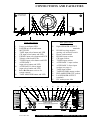
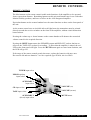
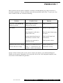
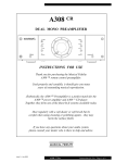
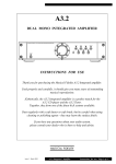
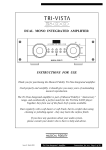
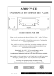
A308
DUAL MONO INTEGRATED AMPLIFIER
MUSICAL FIDELITY A308
DUAL MONO AMPLIFIER
PHONO
AUX 1
CD
AUX 2
TUNER
POWER
TAPE
MUTE
TAPE MONITOR
I.R.R.
INSTRUCTIONS FOR USE
Thank you for purchasing the Musical Fidelity A308 Integrated amplifier.
Used properly and carefully, it should give you many years of outstanding
musical reproduction.
Æsthetically, the A308 Integrated amplifier is a perfect match for the
A308 CR CD player.
Together, they form one of the finest hi-fi systems available.
Dust regularly with a soft duster or soft brush, but be careful when using
cleaning or polishing agents - they may harm the surface finish.
If you have any questions about your audio system,
please consult your dealer who is there to help and advise.
Issue 3: March 2003
A308 Integrated Amplifier
Instructions for use Page 1 of 9
SAFETY INFORMATION
IMPORTANT!
(U.K. only)
This unit is supplied in the U.K. with a mains lead fitted with a moulded 13 amp plug.
If, for any reason, you need to cut off this plug, please remove the fuse holder and dispose of
the plug safely, out of reach of children. It must not be plugged into a mains outlet.
The wires in the mains lead supplied with this appliance are coloured in accordance
with the following code:
Green and yellow..............Earth
Blue...............................Neutral
Brown................................Live
WARNING - This appliance must be earthed
As the colours of the wires of the mains lead of this appliance may not correspond with the
coloured markings identifying the terminals in your plug, proceed as follows:
The wire which is coloured green-and-yellow must be connected to the terminal in the plug
which is marked with the letter E or coloured green or green-and-yellow, or by the earth
The wire which is coloured brown must be connected to the terminal which is marked with the
letter L or coloured red.
The wire which is coloured blue must be connected to the terminal which is marked with the
letter N or coloured black.
If connecting to a BS1363 plug, a 13 amp fuse must be used.
WARNING:
The A308 Integrated is a powerful amplifier and must necessarily supply high
voltages through the loudspeaker terminals. Therefore, to avoid any possibility of
an electric shock DO NOT TOUCH THE SPEAKER TERMINALS when the unit
is being used. To comply with BSEN60065 safety regulations, the 4mm “banana”
plug holes have been fitted with plastic blanking pieces. Removal of these will
invalidate any electrical safety approval of this product.
WARNING:
Any modifications to this product not expressly approved by Musical Fidelity who
is the party responsible for standards compliance could void the user’s authority to
operate this equipment.
Issue 3: March 2003
A308 Integrated Amplifier
Instructions for use Page 2 of 9
GENERAL ADVICE
INSTALLATION PRECAUTIONS and USER INFORMATION
Your A308 Integrated amplifier is designed and built to provide trouble-free performance, but
as with all electronic devices it is necessary to observe a few precautions:
Heed all warnings shown on the back of the product.
Only connect the A308 amplifier to a mains outlet having the same voltage as marked at the
back of the unit.
Always ensure that when disconnecting and reconnecting your audio equipment the mains
supply is switched off.
Position the mains lead and signal interconnects where they are not likely to be walked on or
trapped by items placed on them.
Do not use near water, or place water-filled containers on the amplifier, for example, flower
vases or potted plants. If water does spill inside, immediately pull out the mains plug from
the wall socket and inform your dealer, who should then check the unit before further use.
Entry of liquid into the amplifier is dangerous, and may cause electric shock or fire hazard.
Do not place the unit near heat sources such as radiators, direct sunlight or other equipment.
The case of this amplifier can run at high temperatures - operate in a well ventilated area, and
do not touch the side heatsink fins after periods of use at high output power.
Do not remove covers or try to gain access to the inside. There are no internal user adjustments. Refer all service work to an authorised Musical Fidelity agent.
NOTE: Unauthorised opening of the equipment will invalidate any warranty claims.
There are fuses inside the A308 Integrated amplifier. In the unlikely event that one blows, refer
the unit to your audio dealer. Do NOT try to replace the fuse yourself as this will invalidate the
warranty.
Dust regularly with a soft duster or soft brush, but be careful when using cleaning or polishing
agents - they may harm the surface finish.
The electronics in modern hi-fi equipment is complex and may, therefore, be adversely affected
or damaged by lightning. For protection of your audio system during electrical storms, remove
the mains plugs and disconnect any aerial lead.
If after-sales service is required, to help your dealer identify the A308 Integrated please quote
the serial number located on the rear panel of the unit.
RADIO FREQUENCY INTERFERENCE (R.F.I)
This product has been tested to ensure that its operation is not adversely affected by normal
background levels of R.F.I., and that it does not itself generate excessive amounts of interference. However, if a problem persists, please contact your Musical Fidelity agent.
Issue 3: March 2003
A308 Integrated Amplifier
Instructions for use Page 3 of 9
CONNECTIONS AND FACILITIES
MUSICAL FIDELITY A308
DUAL MONO AMPLIFIER
PHONO
AUX 1
CD
AUX 2
TUNER
POWER
1
TAPE
MUTE
2
3
4
5
6
7
8
9
10
Front panel layout
1
2
3
4
5
6
7
8
9
10
11
12
13
15
16
14
15
16
17
18
19
20
21
22
23
24
17
18
19
20
21
22
PHONO
MM
CD
TUNER
AUX 1
HOME
THEATRE
DIRECT
23
24
TAPE
TAPE
REC
PRE
OUT
MC
MOUNT UNIT ON SOLID SURFACE.
DO NOT REMOVE SCREWS ORCOVERS
UNDER ANY CIRCUMSTANCES.
NO USER SERVICEABLE COMPONENTS INSIDE.
REFER SERVICING TO QUALIFIED ENGINEER.
SEE OWNERS MANUAL FER FURTHER INFORMATION.
+
50/60Hz
+
RIGHT SPEAKER
OUTPUT
-
Issue 3: March 2003
25
POWER
CONSUMPTION
550W
AUX 2
CAUTION
12
Right SPEAKER OUTPUT
terminals
PHONO moving magnet /
moving coil selection switch
Phono earth terminal
PHONO input sockets
CD input sockets
TUNER input sockets
AUXILIARY 1 input sockets
AUXILIARY 2 direct input
sockets (see page 6)
TAPE input sockets
TAPE RECORD output sockets
PRE-AMPLIFIER OUT sockets
Left SPEAKER OUTPUT
terminals
IEC mains power inlet
25
14
11
Back panel layout
Power on indicator LED
POWER on/off switch button
MUTE LED
TAPE input select button and LED
CD input select button and LED
PHONO input select button and LED
Volume control and LEDs
TUNER input select button and LED
AUXILIARY 1
input select button and LED
AUXILIARY 2 (direct input)
input select button and LED
Infra Red Remote receiver for
remote control
TAPE MONITOR button and LED
13
TAPE MONITOR
I.R.R.
MUSICAL FIDELITY
A308 DUAL MONO INTEGRATED AMPLIFIER
+
LEFT SPEAKER
OUTPUT
MANUFACTURED IN ENGLAND BY MUSICAL FIDELITY
-
-
A308 Integrated Amplifier
+
THIS APPLIANCE
MUST BE
EARTHED
-
IMPORTANT
CC
Instructions for use Page 4 of 9
REMOTE CONTROL
REMOTE CONTROL
The blue buttons on the remote control enable main functions of the amplifier to be operated
from a convenient distance. Remaining buttons on this universal handset are for use with other
Musical Fidelity products, and have no effect on the A308 Integrated amplifier.
Equivalent buttons on the remote handset have the same functions as those on the front panel of
the unit.
As the remote control uses an invisible infra-red light beam, the transmitter must be pointed
directly towards the receiver window on the front of the amplifier, without visual obstruction
between them.
Pressing the volume-up or -down buttons on the remote handset will advance the motorised
volume control in the required direction.
Pressing the MUTE button mutes the SPEAKER output and PRE-OUT sockets, but has no
effect on the TAPE OUT sockets for recording. To show that the amplifier is muted, the red
LED on the front panel will light. Press the MUTE button again to cancel mute function, and
the LED will go off.
If the range of the remote control greatly decreases, replace the batteries with new ones.
Do not mix old and new batteries - two are required, type SUM-4, AAA or LR03.
TUNER input select
PHONO pickup
input select
AUXILIARY 1
input select
CD input select
VOLUME (UP)
TAPE input select
VOLUME (DOWN)
AUXILIARY 2
(direct) input select
Issue 3: March 2003
MUTE button
A308 Integrated Amplifier
Instructions for use Page 5 of 9
CONNECTIONS
All input, output and power connections
should be made with the mains power
switched OFF.
INPUT CONNECTIONS
The A308 integrated amplifier has one pair
of phono inputs, which can be used either
for moving magnet (MM) or the lower output moving coil (MC) pickups.
The phono input sensitivity requirement
can be changed from MM to MC by pressing the MM/MC push-button switch located on the rear panel.
Important - Do not operate the MM/MC
switch with the volume control turned up.
Some turntable/pickup arm combinations
are fitted with an extra wire for chassis
earthing. This should be connected to the
earth terminal on the back panel.
The A308 also has four “line level” inputs
controlled by the internal volume setting.
They all have the same input sensitivity,
and are therefore suitable for use with any
source component having an output of at
least 300mV. The four sockets on the rear
panel are marked CD, TUNER, AUXILIARY 1, and TAPE, corresponding with
function selector buttons on the front
panel.
The AUXILIARY 2 (HOME THEATRE
sockets are intended for home theatre use. When selected, they are routed
inside the A308 directly to the power
amplifier circuit, which is not controlled
by the volume adjustment.
Do not therefore connect these sockets to a
source without its own volume control.
DIRECT)
Using good quality co-axial audio leads,
connect the left and right outputs from your
CD player to the CD sockets, your tuner to
the TUNER sockets and any other source
to the AUXILIARY 1 RCA input sockets.
Connect the A308’s TAPE input sockets to
the line output of your tape recorder, and
A308’s TAPE RECORD output sockets to
the line input sockets of the tape deck.
OUTPUT CONNECTIONS
Connect your loudspeakers to either of the
two pairs of terminals on the back panel
marked as LEFT and RIGHT SPEAKER
outputs. Note: the combined load impedance must not be less than 4 ohms.
PRE-AMPLIFIER OUTPUT
The A308 amplifier has its pre-amplifier
output available from RCA sockets on the
back panel marked PRE-OUT, and is controlled by the volume adjustment.
This is to allow “bi-amplification” using
suitable external amplifiers and crossover
networks to power the speaker drive components separately, giving noticeable
improvement in clarity, imaging and bass
weight.
In this arrangement, typically the A308’s
speaker outputs are used to drive the speaker’s “tweeter” (high audio frequencies), and
an external stereo amplifier drives the
“woofer” (low frequencies).
The A308’s PRE OUT RCA sockets
would therefore be connected to the input
of the external “woofer” amplifier in this
example.
(continued....)
If you are in doubt about bi-amplification,
please contact your dealer for advice.
Issue 3: March 2003
A308 Integrated Amplifier
Instructions for use Page 6 of 9
OPERATION
BEFORE SWITCHING ON
TAPE RECORDING
Plug the accessory IEC mains lead into the
rear panel socket, then the other end into a
wall outlet.
To record, simply select the required source
with the input selector button on the front
panel. This source will now be routed to the
A308’s TAPE RECORD output for recording by the external tape deck.
You will also be able to hear the selected
source through the loudspeakers.
Turn the volume control on the front panel
to minimum (anticlockwise).
STARTING . . . .
Press the POWER button on the A308
amplifier - the blue power LED on the front
panel will light indicating that the unit is
ready for use. However, for about five seconds no sound will be heard from your
speakers, and the red mute LED will light to
confirm initial mute action.
Unless using your amplifier for off-tape
monitoring (see paragraph opposite
)
ensure that the TAPE MONITOR button
has not been pressed accidently, as otherwise no sound will be heard through the
speakers.
Select the required audio input source by
pressing an appropriate function button on
the front panel or the remote control, and
adjust the volume control to obtain the preferred sound level.
Note - adjustment of the volume control has
no effect on the recording level.
OFF - TAPE MONITORING
In conjunction with a 3-head cassette deck,
off-tape monitoring allows the user to compare the recorded sound with the original
whilst a recording is being made. To do
this, first select the required source in the
normal way and start recording.
The MONITOR button on the front panel
can now be used to switch between the
source signal and the recorded version
allowing direct comparison.
The red LED just above the MONITOR
button confirms that the tape monitor function is operating.
Note that the recorded signal is selected
when this LED is lit. On some 3-head tape
decks there is an additional 'tape/source'
switch which must be in the 'tape' position
for the above to work.
If in doubt, please refer to your tape deck
operating manual.
Issue 3: March 2003
A308 Integrated Amplifier
Instructions for use Page 7 of 9
PROBLEMS ?
Basic problem-solving with an amplifier is similar to troubleshooting any other electrical or
electronic equipment. Always check the most obvious possible causes first. To give you a few
ideas of what to look for, check the following:
Problem
Possible Cause
Remedy
No power when POWER
button is pressed
Mains plug not inserted
fully into rear socket
Plug in securely
No sound
Tape monitor function has
been selected
Switch off tape monitor
Mute function is still active
(mute LED is on)
Press the mute button again
to cancel
Wrong connections between
input sources and the A308
Check audio input lead
connections
Speakers not connected, or
incorrectly wired
Check speaker cables
Sound is not precise, lacking Speakers are connected out of
in bass and stereo image
phase, i.e., connections to one
speaker (+ and -) are reversed
Ensure speakers are
connected correctly
If none of these actions effect a cure, please contact your dealer, or an authorised Musical
Fidelity service agent. Remember, never open the case of the A308 integrated amplifier yourself, as this will invalidate the guarantee.
Issue 3: March 2003
A308 Integrated Amplifier
Instructions for use Page 8 of 9
A308
SPECIFICATIONS :
Dual Mono Integrated Amplifier
Output: Voltage RMS:
Peak:
Power:
35 Volts 20Hz to 20kHz
99 Volts
150 Watts per channel into 8 Ohms (21.8dBW),
300 Watts per channel into 4 Ohms
48 Amps
140
4
50 Ohms
Peak-to-peak output current:
Damping factor:
Output devices per channel:
Pre-output impedance:
Line inputs:
Total harmonic distortion + noise, 20Hz to 20kHz
Signal / noise ratio
Input sensitivity for 150 Watts into 8 Ohms
Input impedance
Overload margin
Channel separation
Frequency response
< 0.008%
> 100dB ‘A’-weighted
270mV
220k Ohms
26dB
> 70dB 20Hz to 20kHz
20Hz to 20kHz, +0, -0.2dB
Auxilliary 2 (Home Theatre Direct) input:
Input sensitivity
30dB gain (31.5 times) nominal
Phono input:
Frequency response reference
IEC RIAA - see graph....
20
15
RIAA RESPONSE
10
5
dB 0
RIAA
-5
A308
-10
RIAA/IEC
-15
-20
16
32
63
125
250
500
1.2K
2.5K
5K
10K
20K
FREQUENCY
Signal / noise ratio
> 96dB Moving Magnet
> 89dB Moving Coil
Input sensitivity
2.5mV Moving Magnet
350µV Moving Coil
Input impedance
47k Ohms
Overload margin
24dB
‘A’-weighted
‘A’-weighted
Inputs:
4 pairs line level RCA connectors,
1 pair (Aux 2) direct power amplifier input RCA connectors,
1 pair phono (MC or MM, switchable) RCA connectors
Outputs:
2 amplifier channels via 2 pairs per channel binding posts.
1 pair RCA audio outputs controlled by the volume,
1 pair RCA tape record fixed line level output.
Power requirement:
100 / 115 / 230Volts AC 50 / 60Hz (factory pre-set),
550 Watts maximum into 8 Ohms
39 Watts idle
Weight:
Dimensions:
20.5 kg, 45.5 lbs unit only, unboxed
23.5 kg, 48.5 lbs in shipping carton
Standard accessories:
440 mm, 17.3 inches wide
143 mm, 5.6 inches high including feet
420 mm, 16.5 inches deep including terminals
IEC type mains lead, remote control (universal), 2 batteries (type SUM-4, AAA, LR03)
Musical Fidelity reserves the right to make improvements which may result in specification or feature changes without notice.
Issue 3: March 2003
A308 Integrated Amplifier
Instructions for use Page 9 of 9