1
Preface
Preface
Thank you for buying ALPHA6000 series inverter made by Shenzhen ALPHA Inverter
Co., Ltd.
To satisfy the high performance needs, ALPHA6000 series inverters use magnetic flux
vector control method to achieve high torque at low speed and low-noise at steady
running. The inner PID operation can perform PID close loop control easily.
ALPHA6000 proprietary features include the advanced automatic torque compensation,
multiple controlling methods, up to 36 fault protections and warning functions. Online
watching and changing parameters, Integrated RS485 Interface, and operation flexibility.
In addition, Energy Saving Running can furthest improves the motor power factor and
efficiency.
ALPHA6000 series are suitable for almost all motor driving applications like paper
process, textile machines, food process, cement, spinning weaving and dyeing,
metallurgy, Iron and steel, and other machinery.
The inverter has wide speed-adjusting range, stable operation, high accuracy and reliable
performance. It can be widely used in application of electrical power energy saving.
If you have some problem that can’t be solved in operation, please contact the nearest
local agents or service center, or contact our company directly.
To ensure the perfect use of this product and the safety of user, please read the user
manual carefully before the operation of inverter and keep the manual in proper place for
future reference.
The information contained in this manual is subject to change without notice.
Before mounting, wiring and commissioning the inverter, to ensure the safety of user and
extending the life of this equipment, it strongly suggested that we must read the safety
rules warnings listed in this book and cautions marked on the inverter.
When in operation, we must pay attention to the situation of driven load and all notes that
related on safety.
1
Preface
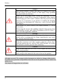
Danger!
This system contains voltages that may be as high as 400 volts!
Electric shock can cause serious or fatal injury. Only qualified
personnel shall wire the drive.
Please cut off the power before wiring and inspecting. It is not
permissible to touch PCB or interior components before battery
control lamp goes off or until 5 minutes after the power has been
removed. It is necessary to use meters to confirm the charging
capacitance has discharged off. Otherwise, a risk of electric shock
may happen.
Don't contact AC power source to the output terminals U, V, W of
the inverter;
When using the inverter, the earthling terminal of the inverter must
be grounded correctly and reliably according to IEC536 Class 1,
NEC and other applicable standards
Warning!
Unauthorized change of inboard wiring and using accessories,
which sold or recommended by blame manufacturer may cause
fire, electric shock and injury.
Since body static electricity may cause serious damage to MOS
field-effect transistor and other sensitive elements, please don’t
touch the interior devices, such as PCB, IGBT module .etc. before
any measure is took to prevent static electricity.
Caution!
Keep all marks and labels are clear to read. Replace the lost or worn
mark at any moment.
Please keep the user manual near the inverter that can be reached
easily and give this manual to the users who use the product.
All rights reserved. The contents in this document are subject to change without notice.
If you have any questions and problems about the use of our products, Please contact our
agents or us.
Any improved suggestions are welcome.
2
Contents
Contents
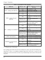
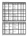
Preface ............................................................................................................................ 1 Contents .......................................................................................................................... 3 Chapter 1 Purchase Inspection ........................................................................................ 6 1.1 Unpacking Inspection ....................................................................................... 6 1.2 Naming Rule ..................................................................................................... 6 1.3 Nameplate of Inverter ....................................................................................... 6 Chapter 2 Installation and Wiring ................................................................................... 7 2.1 Exterior Size and Mounting Size (See Appendix 1) ......................................... 7 2.2 Mounting Place Requirement and Management ............................................... 7 2.2.1 Installation Location .................................................................................. 7 2.2.2 The Ambient Temperature ......................................................................... 8 2.2.3 Preventive Measures .................................................................................. 8 2.3 Installation Direction and Space ....................................................................... 8 2.4 Main Circuit Wiring.......................................................................................... 8 2.4.1 The Main Circuit Terminals Arrangement and wiring............................... 8 2.4.2 Main Circuit Wiring operation................................................................. 14 2.5 Control Circuit Connection ............................................................................. 15 2.5.1 Function of Control Circuit Terminals..................................................... 15 2.5.2 Control Circuit Wiring ............................................................................. 22 2.6 Wiring of Inverter for Basic Operation ........................................................... 34 2.7 Wiring Attention ............................................................................................. 38 Chapter 3 Operation...................................................................................................... 39 3.1 Function of keyboard ...................................................................................... 39 3.1.1 Overview of keyboard ............................................................................. 40 3.1.2 Description of keystroke function ............................................................ 41 3.1.3 Description of LED digitals and indicators.............................................. 43 3.1.4 Display state of keyboard......................................................................... 44 3.1.5 Operation method of keyboard ................................................................ 47 3.2 Run command mode select ............................................................................. 49 3.3 Trial Operation................................................................................................ 49 3
Contents
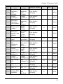
3.3.1 Operation mode of inverter ...................................................................... 49 3.3.2 Before operation checkpoints .................................................................. 52 3.3.3 Operation checkpoints ............................................................................. 52 3.3.4 A trial run ................................................................................................. 52 3.4 Commissioning of keyboard ........................................................................... 54 3.5 Operation of Control Circuit Terminal ........................................................... 55 Chapter 4 Parameter Index ........................................................................................... 56 Chapter 5 Parameter Introductions ............................................................................. 106 5.1 Basic Function (Group P0) ........................................................................... 106 5.2 Start/Stop Control (Group P1) ...................................................................... 112 5.3 Auxiliary Operation (Group P2) ................................................................... 120 5.4 I/O Terminal Ctrl (Group P3) ....................................................................... 124 5.5 Analog and Pulse Function (Group P4) ........................................................ 143 5.6 PLC Operating (Group P5) ........................................................................... 147 5.7 Wobble Frequency Operating (Group P6) .................................................... 151 5.8 PID Control (Group P7) ................................................................................ 154 5.9 Fixed-length Function (Group P8) ................................................................ 158 5.10 Advanced Control (Group P9) .................................................................... 160 5.11 Motor Parameters (Group PA) .................................................................... 163 5.12 MODBUS Communication (Group Pb) ...................................................... 165 5.13 Display Control (Group PC) ....................................................................... 168 5.14 Protection and Fault Parameters (Group Pd) .............................................. 173 5.15 Running History Record (Group PE) .......................................................... 178 5.16 Protection of parameters (Group PF) .......................................................... 180 Chapter 6 Troubleshooting ......................................................................................... 184 6.1 Troubleshooting ............................................................................................ 184 6.2 Warning display and explanation.................................................................. 189 6.3 Motor’s faults and corrective measure .......................................................... 190 Chapter 7 Peripheral Equipments ............................................................................... 192 7.1 Peripheral Equipments Connection Diagrams: ............................................. 192 7.2 Function of Peripheral Equipments .............................................................. 194 7.2.1 AC reactor.............................................................................................. 194 7.2.2 EMI Filter .............................................................................................. 195 7.2.3 Brake unit and resistor ........................................................................... 196 4
Contents
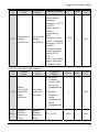
7.2.4 Leakage current protector ...................................................................... 197 7.2.5 Capacitor Box ........................................................................................ 197 Chapter 8 Maintenance ............................................................................................... 198 8.1 Inspection and Maintenance ......................................................................... 198 8.1.1 Daily Inspection ..................................................................................... 198 8.1.2 Regular Maintenance ............................................................................. 199 8.1.3 Replace device at regular intervals ........................................................ 202 8.2 Storage and Keeping ..................................................................................... 202 Chapter 9 Quality Guarantees ..................................................................................... 203 Appendix 1 Exterior size and mounting size (Unit: mm) ................................... 205 Appendix 2 Technology Standards ..................................................................... 210 Appendix 3 Main Circuit Output Cable Selection (Recommended)................... 213 Appendix 4 MODBUS Communication ............................................................. 215 Appendix 5 Keyboard Mounting Size (Unit: mm) ............................................. 232 Appendix 6 Inverter warranty ............................................................................. 234 5
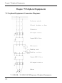
Chapter 1 Purchase Inspection
Chapter 1 Purchase Inspection
1.1 Unpacking Inspection
All inverters have passed the strict tests before delivery. After unpacking, please check if
the product was damaged by careless transport; the product specification, model is
complied with the order, and if it has a quality check passed mark. If there is any problem,
please contact the supplier.
1.2 Naming Rule
The naming rule of the product is as following:
ALPHA6000 - 3 7R5 G B
Series Code
Rated Voltage
Motor Power
Application
S2: single phase220V
R75: 0.75KW
G: General
2: three phases220V
7R5: 7.5KW
P: Square torque load
3: three phases380V
075: 75KW
Additional description
B: With brake;
Attention: If the user has special needs, please specify the technology requirement
in the order.
1.3 Nameplate of Inverter
On the right side of the bottom plate of inverter, there is a nameplate, which marks the
model and rated values of inverter. See the following figure:
Inverter types
Rated input voltage、current and frequency
Motor output power、rated current and frequency
Barcode information
Nameplate of Inverter
6
Chapter 2 Installation and Wiring
Chapter 2 Installation and Wiring
2.1 Exterior Size and Mounting Size (See Appendix 1)
2.2 Mounting Place Requirement and Management
Attention
· Don’t carry the inverter by its cover. The cover cannot support the weight of the
inverter and may drop.
· Please install the inverter on a strong support, failing which the inverter may fall off.
· Don’t install the inverter in places where water pipes may leak onto it.
· Don’t allow screws, washers and other metal foreign matters to fall inside the
inverter, otherwise there is a danger of fire or damage.
· Don’t operate the inverter if parts are not complete, otherwise there is a danger of
fire or human injury.
· Don’t install the inverter under direct sunshine; otherwise, it may be damaged.
· Don’t short circuit PB, + and -, otherwise there is a danger of fire or the inverter may
be damaged.
· Cable lugs must be connected to main terminals firmly.
· Don’t apply supply voltage (AC 220V or higher) to control terminals except
terminals TA,TB,TC.
Please mount the inverter as following application occasions and maintain appropriate
condition.
2.2.1 Installation Location
The installation location should meet the following conditions:
●Good indoor ventilation;
●Ambient temperature: -10 ℃ ~ 40 ℃. If the temperature is higher than 40 ℃, the
inverter should be derating used and forced ventilation is required;
●Humidity should be lower than 95%, no condensing;
●Do not mount the inverter on the timber or other combustible matters;
●Avoid direct sunlight;
●Mount in the location free of dust, metal powder, corrosive gas or combustible gas;
●The installation foundation should be solid and free of vibration;
●No electromagnetic interference, away from source of interference;
●Derating use must be considered when the inverter is installed at high altitude, greater
than 1000 m. This is because the cooling effect of inverter is deteriorated because of the
thin air. Derating 6% per 1000 m higher of the altitude.
7
Chapter 2 Installation and Wiring
2.2.2 The Ambient Temperature
In order to enhance operating reliability of the inverter, be sure where the inverter
mounted has a good ventilation; when the inverter is used in a closed case, cooling fans
or an air-conditioning must be installed to keep the ambient temperature below 40℃.
2.2.3 Preventive Measures
Installing the inverter, please set a shield to prevent metal debris falling into it, and
remove the shield after installing.
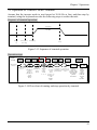
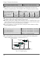
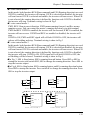
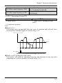
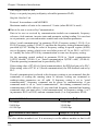
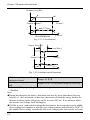
2.3 Installation Direction and Space
Inverters of this series are all equipped fans for forced cooling. In order to be an effective
cooling cycle, the inverter must be mounted in the vertical direction, up, down, left and
right away from adjacent articles or baffle(wall) maintain adequate space, as Figure 2-1
120mm
or above
50mm
or above
50mm
or above
120mm
or above
Fig 2-1 Installation Direction and Space
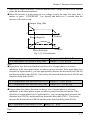
2.4 Main Circuit Wiring
2.4.1 The Main Circuit Terminals Arrangement and wiring
8
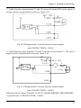
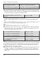
Chapter 2 Installation and Wiring
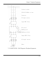
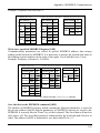
Fig 2-2 S2R4GB~S2R75GB Main Circuit Wiring
Table2-1 S2R4GB~S2R75GB main circuit terminals function
Terminal Symbol
Terminal name and function
L,N
Single-phase 220V AC supply input terminals
+,PB
Reserved terminals for braking resistor
U,V,W
Three -phase AC output terminals
PE
Earth terminal
Fig 2-3 S21R5GB~S22R2GB Main Circuit Wiring
Table2-2 S21R5GB~S22R2GB main circuit terminals function
Terminal Symbol
Terminal name and function
L,N
Single-phase 220V AC supply input terminals
+,PB
Reserved terminals for braking resistor
Output terminal for DC negative bus
U,V,W
Three-phase AC output terminals
PE
Earth terminal
9
Chapter 2 Installation and Wiring
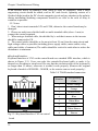
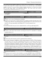
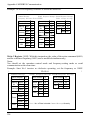
Fig 2-4 3R75GB~3004GB Main Circuit Wiring
Table2-2 3R75GB~3004GB main circuit terminals function
Terminal Symbol
Terminal name and function
L,N
Three -phase 220V AC supply input terminals
+,PB
Reserved terminals for braking resistor
Output terminal for DC negative bus
U,V,W
Three -phase AC output terminals
PE
Earth terminal
DC
reactor
Power supply
PE cable
core and
screen
Braking
resistor
Motor
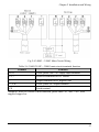
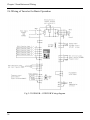
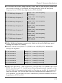
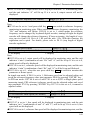
Fig 2-5 35R5GB/37R5PB~3015GB/3018PB Main Circuit Wiring
10
Chapter 2 Installation and Wiring
Table 2-4 35R5GB/37R5PB~3015GB/3018PB main circuit terminals function
Terminal Symbol
Terminal name and function
R,S,T
Three -phase 380V AC supply input terminals
P1,+/B1
Reserved terminals for DC reactor
+/B1,B2
Reserved terminals for braking resistor
Output terminal for DC negative bus
U,V,W
Three -phase AC output terminals
PE
Earth terminal
Attention: When DC reactor is not connected, please short “P1”and “+/B1”with supplied
copper bar.
PE cable
core and
screen
Braking
Unit
Power supply
Braking
resistor
DC
Motor
reactor
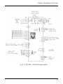
Fig 2-6 3018G/3022P~3055G/3075P Main Circuit Wiring
11
Chapter 2 Installation and Wiring
Table 2-5 3018G/3022P~3055G/3075P main circuit terminals function
Terminal
Function
R,S,T
Three -phase 380V AC supply input terminals
P1,+
Reserved terminals for DC reactor
Output terminal for DC negative bus
U,V,W
Three -phase AC output terminals
PE
Earth terminal
Attention: When DC reactor is not connected, please short “P1” and “+/B1” with
supplied copper bar.
Fig 2-7 3160G/3185P~3355G/3400P Main Circuit Wiring
12
Chapter 2 Installation and Wiring
Fig 2-8 3400G~3500G Main Circuit Wiring
Table 2-6 3160G/3185P~3500G main circuit terminals function
Terminal
Function
R,S,T
Three -phase 380V AC supply input terminals
P1,+
Reserved terminals for DC reactor
-
Output terminal for DC negative bus
U,V,W
Three -phase AC output terminals
PE
Earth terminal
Attention: When DC reactor is not connected, please short “P1” and “+/B1” with
supplied copper bar.
13
Chapter 2 Installation and Wiring
2.4.2 Main Circuit Wiring operation
Be sure that the motor is running forward when the running direction command of
inverter is forward. If the motor is running reverse, interchange any two output terminals
(U, V, W) can change the rotate direction of the motor, and you can change function code
P2.25 to change phase-sequence of the motor.
Never connect input power supply cables to output terminals, or else parts of the inverter
would be damaged. Do not connect output terminals to earth, be sure output cables not
touch to the shell or be shorted, or else the inverter would be damaged.
Be sure Earth terminal “PE” is connected to earth. The earthling resistance of 380V-class
should be below 10Ω. Be sure the earthling not be shared with an electric welding
machines or other high-current electrical equipments. Use ground wiring as mentioned
in “Appendix 3 Main Circuit Output Cable Selection” and keep the length as short as
possible.
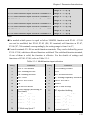
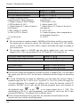
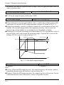
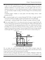
When two or more inverters are used at the same time, do not loop the wires. The right
and wrong earthling connection methods are shown as Figure 2-9.
Right
Wrong
Inverter
Inverter
Inverter
Inverter
Inverter
Inverter
Fig 2-9 Earthling Connection Method
Attention: The neutral point of motor using Y connection can’t be connected to
earth.
Since the inverter output PWM wave, if a capacitance for improving power factor or a
lightning varistor is installed on the output side, which would case tripping or damage to
parts, be sure to remove it.
If a contactor or other on-off part is needed to be installed between the output and the
motor, be sure the on-off operation is done when the inverter has no output, otherwise the
inverter would be damaged.
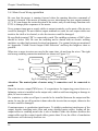
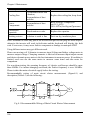
Countermeasures to conduction interference: To inhibit conduction interference of the
output, besides installing noise filter and using shielded motor cables, leading all the
output cables to earthling metal tube is also a method. Make the distance between the
output cables and the control signal cables greater than 30 cm, the effect of conduction
interference will obviously decrease too.
14
Chapter 2 Installation and Wiring
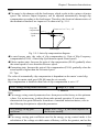
Countermeasures to RFI: The input cables, output cables and the inverter itself would
produce RFI. Placing noise filters both at input and output sides, and shielded with metal
shell would reduce RFI. The cables between the inverter and the motor should be as short
as possible. Measure to reduce RFI is shown as Figure 2-10.
Metal shell box
Metal tube
Power
supply
Noise
Filter
Inverter
Noise
Filter
Motor
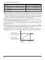
Fig 2-10 Method to Restrain RFI
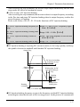
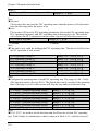
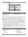
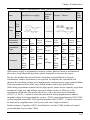
Distance between the inverter and the motor.
The longer the distance between the inverter and the motor, the higher the carrier
frequency would be, and the greater the high harmonic leakage current of the cables
would be. Leakage current has a negative impact to inverters and equipments nearby, so
reduce leakage current as little as possible.
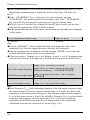
The relationship of the distance between the inverter and the motor and carrier frequency
is shown as Table 2-7.
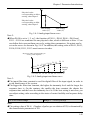
Table 2-7 Distance between the inverter and the motor and carrier frequency.
Distance between inverter
Below 50m
Below 100m
Above 100m
and motor
Carrier frequency
Below 8 kHz
Below 4 kHz
Below 2 kHz
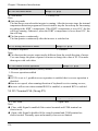
2.5 Control Circuit Connection
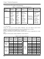
2.5.1 Function of Control Circuit Terminals
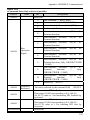
Fig 2-11 S2R4GB~3004GB Arrangement of Control Circuit Terminals
15
Chapter 2 Installation and Wiring
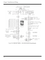
Fig 2-12 35R5GB/37R5PB~3500GB Arrangement of Control Circuit Terminals
In order to reduce interference and attenuation of control signal, the length of control
cables should be limited in 50 m and away from power cables for more than 30 cm.
Avoid control wire and power wire being parallel. Try to use STP (Shielded Twisted Pair)
to connect analog input and output signal.
● Function of Control Circuit Terminals
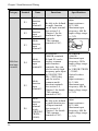
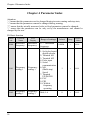
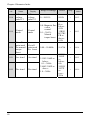
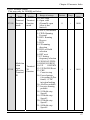
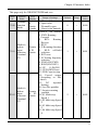
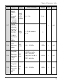
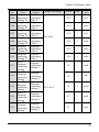
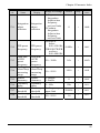
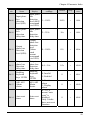
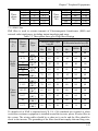
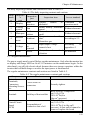
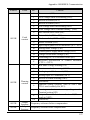
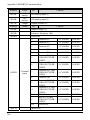
Table 2-8 Function of control circuit terminals
Category
Terminal
AI1
Name
Analog
input1
Analog
input
AI2
16
Analog
input2
Functions
Specifications
Be able to accept
voltage/current input.
Data-chosen-switch
SW1 can select
voltage or current
input mode. Voltage
input mode is the
default mode, refer to
P4.00~P4.10 to set
the range.(The
reference ground is
GND)
Input voltage range:
0~10 V
(Input resistance:
100 kΩ)
Input current range:
0~20 mA
(Input resistance:
500Ω)
Chapter 2 Installation and Wiring
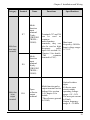
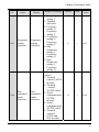
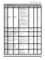
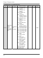
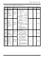
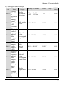
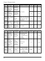
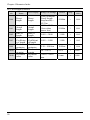
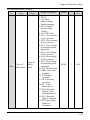
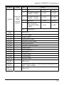
Category
Terminal
AO1
Name
Analog
output1
Analog
output
AO2
Analog
output2
(only
35R5GB/3
7R5PB~
3500G)
485+
Functions
Be able to output
analog voltage
/current (total 12
kinds of
signals).Switch SW2
can select voltage or
current output mode.
Voltage output mode
is the default mode.
Refer to P4.16 for
details. (The
reference ground is
GND)
Be able to output
analog voltage
/current (total 12
kinds of
signals).Switch SW3
can select voltage or
current output mode.
Voltage output mode
is the default mode.
Refer to P4.17 for
details. (The
reference ground is
GND)
RS485+
RS485
communic
ation
interface
Communi
cation
485-
RS485-
Specifications
Output current
range: 0/4~20 mA
Output voltage
range: 0/2~10 V
Standard RS-485
communication
interface
Not isolate with
GND
Please use
twisted-pair or
shielded cable
17
Chapter 2 Installation and Wiring
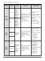
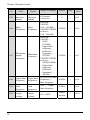
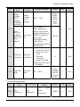
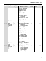
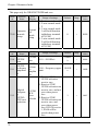
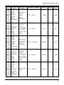
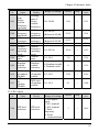
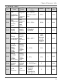
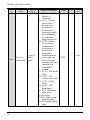
Category
Terminal
X1
X2
X3
Mult-func
tion input
terminal
18
Name
Multifunction
input
terminal 1
Multifunction
input
terminal 2
Multifunction
input
terminal 3
X4
Multifunction
input
terminal 4
X5
Multifunction
input
terminal 5
X6
Multifunction
input
terminal
6(only
35R5GB/3
7R5PB~
3500G)
Functions
Be able to be defined
as multi- function
on-off input terminal.
See section 5.4 ,
Chapter 5 for the
function of input
terminals
(The common
terminal is PLC)
Specifications
Optical-isolator
input
Input resistance:
R=3.9 kΩ
Maximum input
frequency: 400 Hz
Input voltage range:
0~30V
24
+24
PLC
+5V
R
X1 ~
COM
In S2R4GB~
3004GB, terminals
X4 and X5 can be
used as common
multi-function
terminals, they can
also be used as high
frequency pulse input.
In 35R5GB/37R5
PB~3500G, they
only be used as
common multifunction terminals
See section 5.4,
Chapter 5 for details.
(The common
terminal is PLC)
Be able to be defined
as multi-function onoff input terminal.
See section 5.4,
Chapter 5 for details.
(The common
terminal is PLC)
In S2R4GB~
3004GB
Maximum input
frequency: 50 Hz
Input voltage range:
0~30V
In 35R5GB/37R5PB
~3500G:
Optical-isolator
input
Input resistance:
R=3.9 kΩ
Maximum input
frequency: 400 Hz
Input voltage range:
0~30V
Optical-isolator
input
Input resistance:
R=3.9 kΩ
Maximum input
frequency: 400 Hz
Input voltage range:
0~30V
Chapter 2 Installation and Wiring
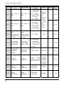
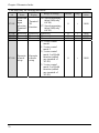
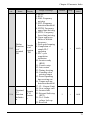
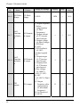
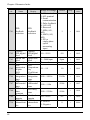
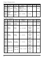
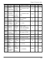
Category
Terminal
Name
X7
Multifunction
input
terminal
7(only
35R5GB/3
7R5PB~
3500G)
Mult-func
tion input
terminal
X8
Multi-fun
ction
output
terminal
DO
Multifunction
input
terminal
8(only
35R5GB/3
7R5PB~
3500G)
Open
collector
output
terminal
Functions
Specifications
Terminals X7 and X8
can be used as
common
multi-function
terminals; they can
also be used as high
frequency
pulse
input. See section 5.4,
Chapter 5 for details.
(The
common
terminal is PLC)
Max input
frequency: 50 KHz
Input voltage range:
0~30 V
Multi-function pulse
output terminal can be
defined. See section
5.4, Chapter 5 for
details.
(The reference ground
is COM)
Optical-isolator
input
Collector open
circuit output
operating voltage
range : 0V~26V
The max put current
is 50mA
Output frequency
range: 0~50 KHz
19
Chapter 2 Installation and Wiring
Category
Terminal
Y1
Multi-fun
ction
output
terminal
Y2
Name
Bi-directio
n open
collector
output
Y1(only
35R5GB/3
7R5PB~
3500G)
Bi-directio
n open
collector
output
Y2(only
35R5GB/3
7R5PB~
3500G)
Functions
Specifications
Multi-function on-off
output terminal can be
defined .See section
5.4, Chapter 5 for
details.
(The common
terminal is CME)
Optical-isolator
output
Operating voltage
range: 0 V~26 V
Max output current:
50 mA
Refer to the
description of
P3.14~P3.15 for
the using methods.
Multi-function output
terminal of relay can
be defined. See
section 5.4, Chapter 5
for details.
TA-TB: Normally
close;
TA-TC: Normally
open.
Capacity of contacts:
250 VAC/2 A
(COSΦ=1)
250 VAC/1 A
(COSΦ=0.4)
30 VDC/1 A
Multi-function output
terminal of relay can
be defined. See
section 5.4 Chapter 5
for details.
BRA-BRB:
Normally close;
BRA-BRC:
Normally open.
Capacity of contacts:
250 VAC/2 A
(COSΦ=1)
250 VAC/1 A
(COSΦ=0.4)
30 VDC/1 A
TA
Relay
output
terminals
TB
Programm
able relay
output
TC
BRA
Relay
output
terminals
BRB
BRC
20
Programm
able relay
output
(only
35R5GB/3
7R5PB~
3500G)
Chapter 2 Installation and Wiring
Category
Terminal
Functions
Specifications
10V
+10V
power
supply
Provide +10V
reference power
supply for external
equipment.
(The reference ground
is GND)
Max output current:
30 mA,
Max voltage when
open is 12 V
24V
+24V
power
supply
Provide +24V
power supply for
external equipment.
(The reference ground
is COM)
Max output current
is 200 mA
PLC
Common
terminal of
multifunction
input
terminal
Common terminal of
multi-function input
Be shorted to 24 V
before delivery
PLC is internal
isolated with 24 V.
GND
Reference
ground of
+10V
power
supply
Reference ground of
analog signal and+
10V power supply
Internal isolated
with COM,
Common terminal of
+10V,AI1,AI2,AO1(
or AO1,AO2)
COM
Common
terminal of
+24V
power
supply
Be used in
conjunction with
other terminals.
COM is internal
isolated with GND.
CME
Common
terminal of
Y1,Y2(onl
y
35R5GB/3
7R5PB~
3500G)
Common terminal of
multi-function Y1
and Y2 output
(Be shorted to COM
before delivery)
Be shorted to COM
before delivery
CME is internal
isolated with
COM,GND
Power
supply
Name
21
Chapter 2 Installation and Wiring
Category
Terminal
Power
supply
PE
Name
Shielding
ground
Functions
Specifications
It is used for
grounding of
shielding layer. The
shielding layer of
analog signal
lines,communication
line 485 and motor
cable can be
connected to this port.
It is connected to the
terminal PE in main
circuit.
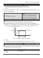
2.5.2 Control Circuit Wiring
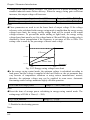
●Wiring analog input terminal
AI1/AI2 can accept analog signal input, operate Data-chosen-switch SW1 to select input
voltage (0~10V) or input current (0~20mA).The wiring is shown as Figure 2-13:
SW1
ON
AI1/AI2
0~+10V
Or 0~20mA
Inverter
GND
Shielded wire near
Grounding
I
PE
V
1
2
AI1
AI2
Fig 2-13 Analogy input terminal wiring diagram
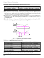
●Wiring analog output terminal
In S2R4GB~3004GB, if the analog output terminal AO1 is connected to analog meters,
the various kinds of physical values can be indicated. Operate wiper switch SW2 to
select output voltage (0/2~10 V) or output current (0/4~20 mA).The wiring is shown
as Figure 2-14:
22
Chapter 2 Installation and Wiring
SW2 SW3
AO1/AO2
Inverter
PE
0/2~+10V
Or 0/4~20mA
GND
Shielded wire
near Grounding
I
V
AO1
AO2
Fig 2-14 S2R4GB~3004GB Analog output terminal wiring diagram
To indicate different kinds of physical values , for models of 35R5GB/37R5PB~
3500G, analog meters can be connected to the analog output terminals of AO1 and
AO2. Switch SW2 and SW3 on and off to select output voltage (0/2~10 V) or current
(0/4~20 mA).The wiring is shown as Figure 2-15:
Inverter
or
Shielded wire
rear Grounding
Fig 2-15 35R5GB/37R5PB~3500G Analog output terminal wiring diagram
Notes:
1)Dialing SW1,SW2,SW3 to“I”represents current, dialing to“V”represents voltage.
2)Analog input and output signals are easily disturbed by exterior environment, so
shielded cables must be used for wiring and the length of the cables should be as short
as possible.
3)When an analog output equipment be connected to the inverter, sometimes because
of error act because of interference cased by the analog output equipment or the
inverter, when which happened, a 0.01~0.1uF/50V capacitance or a ferrite
bead(enwind 3 laps) could be connected to the analog output equipment.
23
Chapter 2 Installation and Wiring
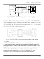
●Wiring of Serial Communication Interface
The inverter of this series provides standard RS485 serial communication interface for
users, which can be composed as master and slave network. By using a host PC or PLC,
The inverter in the network can be monitored in real time and controlled remotely and
automatically. Thus more complicated operation control can be realized.
Connection between the inverter and the host PC:
Host PC
RS232(DB9)
RS232/RS485 converter
Pin NO.
Symbol
Shell
PE
2
RXD
TXD
Data Send
3
TXD
RXD
Data Receive
5
GND
GND
Negative of 5V
4
DTR
6
DSR
Shielded
wire
Terminal Name
+5V
Description
Positive of 5V
Inverter
RS485 communication
interface
9
RI
Terminal Name
Terminal Name
Description
1
CD
signal negative
RS485-
RS485-
signal negative
7
RTS
signal positive
RS485+
RS485+
signal positive
8
CTS
Description
Fig 2-16 Connection between the inverter and the host PC
If several inverters (Max 31) are connected in the network by RS485, wiring is
especially important because the disturbance to the communication system increase,
STP (Shielded Twisted Pair) must be used for communication BUS, you can connect the
cables as follows:
Inverter
PLC
485+
485-
Inverter
Inverter
SG
485+
485-
GND
485+
485-
GND
485+
485-
GND
Shielded wire
Fig 2-17 Communication between PLC and the Inverter
(The Inverter and Motor are grounded well)
The master can be a host PC or a PLC, the slaves are inverters of this series. An
RS232/RS485 converter should be installed between the master and the bus when a PC
24
Chapter 2 Installation and Wiring
is used. Connect homonymy terminals of the master and slave if the master is PLC.
When several inverters of S2R4GB~3004GB formed the RS485 network, you should
customize the matching resistor of the inverters on those control panels which are on
both ends of the farthest of the bus according to the use.
When several inverters of 35R5GB/37R5PB~3500G formed RS485 network, you
should dial SW4 (double switches) of the farthest inverter to “ON”, as Figure 2-18.
SW4
ON
1
2
RS485
Fig 2-18 Switches of SW4
If the communication still can’t work, then the following actions can be taken:
1)Feed a separate AC supply to PLC (or host PC) and isolate the AC supply;
2)If RS232/RS485 converter is used and the module should be powered by a separate
power supply, converter with optical-isolator is recommended;
3)Mount a toroid to the communication cable, or reduce the carrier frequency if the local
conditions permit .
●Wire Multi-function input terminals
Multi-function input terminals of the inverter use a full-bridge rectifying circuit. PLC is
the common terminal of terminals X1~X8(in S2R4GB~3004GB only X1~X5). The
current flows through terminal PLC can be pulling current, and feeding current. Wiring
X1~X8 are flexible and the typical wiring is shown below:
Method 1 of connections (Dry contacts)
1)If internal 24 V power supply is used, the wiring is shown in Figure2-19(Attention:
PLC and 24V must be firmly connected).
25
Chapter 2 Installation and Wiring
+24V
24V
5V
PLC
+
R
K
_
X1~X8
COM
Fig 2-19 Using Internal 24V Power Supply
2)If an external power supply is used, then use the Wiring shown in Figure 2-20
(Attention: be sure to disconnect the cable JP1 between PLC and 24 V for models of
S2R4GB~3004GB; and disconnect the wiring cable between PLC and 24 V for
models of 35R5GB/37R5PB~3500G).
24V
+24V
5V
PLC
+
_ DC
K
+
R
_
X1~X8
COM
Fig 2-20 Use an external supply
●Method 2 of connections
1) Inverter’s internal +24 V power supply is used and the external controller uses NPN
transistors whose common emitters are connected, as shown in Figure 2-21.
26
Chapter 2 Installation and Wiring
External
t ll
24V
COM + 24V DC
—
PLC
5V
X1
1
5V
X8
8
PE
COM
Shield wire near grounding
Fig 2-21 Method 2 of connections (a)
2) Inverter’s internal +24 V power supply is used and the external controller uses NPN
transistors whose common emitters are connected, as shown in Figure 2-22
(Attention: be sure to disconnect the cable JP1 between PLC and 24 V for models of
S2R4GB~3004GB; and disconnect the wiring cable between PLC and 24 V for
models of 35R5GB/37R5PB~3500G, short circuit terminal PLC and COM).
External
ll
COM
24V
COM
PLC
1
+
24V DC
+
5V
X1
5V
8
X8
PE
Shield wire near grounding
Fig 2-22 Method 2 of connections (b)
27
Chapter 2 Installation and Wiring
3) Use external power supply by source connection method (Attention: be sure to
disconnect the cable JP1 between PLC and 24 V for models of S2R4GB~3004GB; and
disconnect the wiring cable between PLC and 24 V for models of 35R5GB/37R5PB~
3500G):
External controller
20~30V
+
—
1
24V
COM
PLC
+24V DC
—
5V
X1
5V
X8
8
PE
Shield wire near grounding
Fig 2-23 Source Connection Method
4) Use external power supply by drain connection method (Attention: be sure to
disconnect the cable JP1 between PLC and 24 V for models of S2R4GB~3004GB; and
disconnect the wiring cable between PLC and 24 V for models of 35R5GB/37R5PB~
3500G):
External controller
20~30V
+
—
1
24V
COM
PLC
+
—24V DC
5V
X1
5V
8
X8
PE
.
Shield wire near grounding
Fig 2-24 Drain Connection Method(in S2R4GB~3004GB only X1~X5)
28
Chapter 2 Installation and Wiring
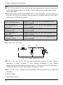
●Wire Multi-function Output Terminals
1) Multi-function output terminals D0 as switching output can use the internal 24V
power supply of inverter and the wiring method is shown in Figure 2-25.
Fig 2-25 Wiring method 1 of DO as switching output
2) Multi-function output terminals D0 as switching output can also use the external 9~
30V power supply and the wiring method is shown in Figure 2-26.
5V
+24V
24V
DO
DC 9~30V
R
+ -
relay
COM
Fig 2-26 Wiring method 2 of DO as switching output
29
Chapter 2 Installation and Wiring
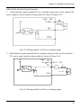
3) Multi-function output terminals / Pulse output terminal DO as pulse output can use
the internal 24 V power supply and the wiring is shown in Figure 2-27.
+24V
+5V
24V
+24V
4.7K
DO
COM
Digital frequency
meter
Fig 2-27 Wiring method 1 of DO as pulse output
4)Multi-function output terminals / Pulse output terminal DO as Pulse output can also
use the external 9~30 V power supply and the wiring is shown in Figure 2-28.
+24V
24V
+5V
+24V
4.7K
DO
_+
COM
20~30V
Digital
frequency
Fig 2-28 Wiring method 2 of DO as pulse output
30
Chapter 2 Installation and Wiring
5)Multi-function output terminals Y1 and Y2 can use the internal 24V power supply of
inverter and the wiring method is shown in Figure 2-29.
Fig 2-29 Wiring method 1 of multi-function output terminal
(only 35R5GB/37R5PB~3500G)
6)Multi-function output terminals Y1 and Y2 can also use the external 9~30V power
supply and the wiring method is shown in Figure 2-30.
5V
+24V
24V
Y1, Y2
DC 9~30V
R
+ -
relay
CME
COM
Fig 2-30 Wiring method 2 of multi-function output terminal
(only 35R5GB/37R5PB~3500G)
●Wiring of Relay Output Terminals TA,TB,TC and BRA,BRB,BRC (BRA,BRB,BRC
is provided only in 35R5GB/37R5PB~3500G)
31
Chapter 2 Installation and Wiring
If the inverter drives an inductive load (such as relay or contactor), then a surge
suppressing circuit should be added, such as RC snub circuit, lightning varistor or a
flywheel diode (used in the DC electric-magnetic circuit and pay attention to the polarity
during installation).Snubbing components should be as close to the coils of relay or
contactor as possible.
Notes:
1.Don’t short circuit terminals 24V and COM, otherwise the control board may be
damaged.
2.Please use multi-core shielded cable or multi-stranded cable (above 1 mm) to
connect the control terminals.
3.When using a shielded cable, the shielded lay’s end that is nearer to the inverter
should be connected to PE.
4.The control cables should be as far away(at least 30 cm) from the main circuit and
high-voltage cables as possible (including power supply cables, motor cables, relay
cables and cables of contactor).The cables should be vertical to each other to reduce the
disturbance to minimum.
●Keyboard Interface
Keyboard Interface of CN3 on the control board uses standard 8PIN interface, which is
shown in Figure 2-31. Users can order the extended keyboard cable or make it by
themselves according to actual need. Be sure that the extension cable of the keyboard is
no longer than 15 meters, otherwise it wouldn’t work properly. (Remove the original
keyboard of models of S2R4GB~3004GB, or the exterior can not work properly.)
Table 2-9 T568B standard connection
Fig 2-31 Keyboard Interface CN2 on control
board
32
Number
Corresponding
Color
1
White/Orange
2
Orange
3
White/Green
4
Blue
5
White/Blue
6
Green
7
White/Brown
8
Brown
Chapter 2 Installation and Wiring
The cables connecting keyboard and control board use standard super-five-class network
cable. RJ-45 Interface uses through-line method, namely both sides are connected
according to EIA/TIA568B standard. You can make the cable by yourself if you need.
Notes:
1.Both sides of keyboard cable should be connected refer to Table 2-6. Otherwise, the
cable couldn’t work properly or even the keyboard would be damaged.
2.When the keyboard extension cable is longer than 1 m, which must use shielded
twist-pair network cable, RJ-45 interfaces of both sides of the cable should use
crystal with shielded metal shell; connect shielded metal shell to shielded layer.
Otherwise, it is likely to cause error action because of disturbance.
3.Be sure the extension cable of the keyboard is no longer than 15 meters, otherwise it
wouldn’t work properly.
33
Chapter 2 Installation and Wiring
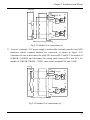
2.6 Wiring of Inverter for Basic Operation
Fig 2-32 S2R4GB~S22R2GB Wiring diagram
34
Chapter 2 Installation and Wiring
Fig 2-33 3R75GB~3004GB Wiring diagram
35
Chapter 2 Installation and Wiring
Braking Resistor
DC reactor
(connect optional (connect optional
parts externally) parts externally)
MC
Motor
Power Supply
3-phase
380V
50/60Hz
Ground
Analog output
4~20mA current
2~10 V voltage
Multi-function input 1
Multi-function input 2
Multi-function input 3
Open collector pulse
output terminal 0~50Khz
Frequency meter
Multi-function input 4
Multi-function input 5
Multi-function input 6
Multi-function input 7
Multi-function input 8
keyboard
Output1 Bi-direction open
Output2 collector output
Common terminal
High speed pulse input
Max input
frequency:
50 KHz
Frequency Reference
Frequence preset
potentiometer
(Input resistance
>500 kΩ)
Ground
Programmable
relay output
Programmable
relay output
RS485 communication
interface
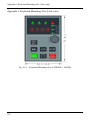
Fig 2-34 35R5GB/37R5PB~3015GB/3018PB Wiring diagram
36
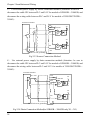
Chapter 2 Installation and Wiring
DCL DC reactor
(connect externally,optional
parts for 3132GB/3160PB or below)
MC
Braking resistor
or braking unit
Motor
Power Supply
3-phase
380V
50/60Hz
Ground
Multi-function input 1
Multi-function input 2
Multi-function input 3
Multi-function input 4
Multi-function input 5
Multi-function input 6
Multi-function input 7
Multi-function input 8
Analog output
4~20mA current
2~10V voltage
Open collector pulse
output terminal 0~50Khz
Frequency meter
keyboard
Output1 Bi-direction open
Output2collector output
Common terminal
High speed pulse input
Max input
frequency:
50 KHz
Frequency Reference
Frequence preset
potentiometer
(Input resistance
>500 kΩ)
Ground
Programmable
relay output
Programmable
relay output
RS485 communication
interface
Fig 2-35 3018G/3022P~3500G Wiring diagram
Notes:
1. Analog signal input to AI1/AI2 (voltage or current) can be selected by
Data-chosen-switch, the default is voltage input. You can refer P4.00~P4.10 to
set the range.
2. Max output current of control circuit terminal 10 V is 30 mA.
3. The cable between PLC and 24 V terminals should be connected firmly
(S2R4GB~3004GB should be sure to disconnect the cable JP1 between PLC and
24 V; 35R5GB/37R5PB~3500G should be sure to disconnect the cable between
PLC and 24V), otherwise input terminals X1-X8 couldn’t work properly(in
S2R4GB~3004GB only X1~X5).
37
Chapter 2 Installation and Wiring
2.7 Wiring Attention
● Be sure the input power supply of the inverter is cut off then you can remove or replace
the motor.
● Be sure the inverter has stopped output then you can switch the motor or the power
supply.
● If a peripheral (brake unit, reactor, filter) is added, test the insulation resistance of the
peripheral to earth first and be sure the value not below 4 MΩ.
● Besides shielding the input signal cable and the cable of frequency meter, the cables
should be disposed solely, not parallel with the main circuit cable, and far away from
it as possible.
● In order to avoid error action caused by molestation, the control circuit cable should
use stranding shielded cables, and the wiring distance should be less than 50 meters.
● Be sure the shielded layers of shielded cables are not touch other signal cables or shell
of equipment, you can use insulating tape to enswathe the bare shielding layer.
● The withstand voltage of all the cables should match with the voltage class of the
inverter.
● In order to prevent accident, be sure that the control circuit terminal ”PE” and the main
circuit terminal “PE” are connected to earth, and the earthling cable can’t be shared
with other equipment. The size of main circuit earthling cable should be more than
one and a half of the main circuit cable. After completion of wiring, please check
whether a cable, a bolt or a connection end .etc., was remained in the inverter, whether
the bolts were fastened firmly, whether the bare cable of terminals were shorted to
other terminals.
38
Chapter 3 Operation
Chapter 3 Operation
DANGER
CAUTION
1, Only turn on the input power supply after replacing the front
cover. Do not remove the cover while the inverter is
powered up.
2, When the retry function is selected, do not approach the
inverter or the load, since it may restart suddenly after
being stopped.
1, Since the stop key can be disabled by a function setting, install
a separate emergency stop switch.
2, Since it is very easy to change operation speed from low to
high speed, verify the safe working range of the motor and
machine before operation.
3, Do not check signals during operation.
4, All inverter parameters have been preset at the factory. Do not
change the settings unless it is required. Failure to observe
these precautions may result in equipment damage, serious
personal injury or death.
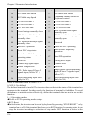
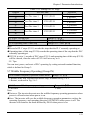
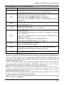
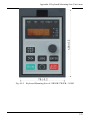
3.1 Function of keyboard
The keyboards of the inverter may have different exterior dimensions. However, all of
them have the same array of keystrokes and LED display. Moreover, operation and
function of them are all the same. Every keyboard has four digitals seven segments LED
monitor, nine operation keystrokes, a digital encoder, and eight led indicators (five for
status indication and three for unit indication ).User can perform function setting,
inverter running, stop, and status monitoring with the keyboard.
39
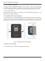
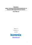
Chapter 3 Operation
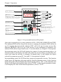
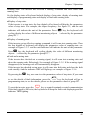
3.1.1 Overview of keyboard
RUN
FWD
REV
REMOTE
TRIP
Status indicator
Frequency:Hz
Hz
r/min
A
%
m/s
V
LED Display
Displays set values of each function
or monitoring values such as output
frequency and current (4 digits).
-
>>
Shift key
RUN key
Green LED lights after depressing
RUN key.
Direction switch key
Percent%
linear speed:m/s
Voltage:V
+
PRG
ESC
Programming key
Roate speed:r/min
Current:A
RUN
Increment key
Decrement key
JOG
ENTER
STOP
RESET
Enter key
Displays each parameter set value.
By depressing this key again,
the set value is saved.
Stop/Reset key
Jog key
Figure 3-1 Layout and function of Keyboard
Above the keyboard are five status indicators: RUN, FWD, REV,REMOTE and TRIP.
The indicator RUN will be lit up if the inverter is running; the indicator FWD will be lit
up if it running forward and the indicator REV will be lit up if it runs reverse. The
indicator REMOTE will be lit up if the inverter is not controlled by keyboard. The
indictor TRIP will be lit up if fault occurs. To see the details, see Chapter 3-3 description.
In monitoring status, the LED will display the content of current monitoring object. At
abnormal state It will display the fault code when the inverter falls to run and show the
warn code when the inverter is warning. At normal state, it will display the object
selected by parameter group PC. See table 3-1 description for details.
In programming status, the LED has three menus to program the inverter: The function
group menu, the function code menu and the function parameter menu. In the function
group menu, the LED will display the function group such as “-P0-”; in the function code
menu, it will display the function code such as “P0.00”; in the function parameter menu,
it will display the value of the function parameter, such as “50.00”.
40
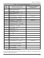
Chapter 3 Operation
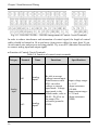
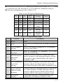
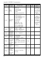
Table 3-1 The LED monitoring objects
Set
value
Monitoring object(Unit)
PC.01=1
Output frequency before
compensation (Hz)
PC.02=1
Actual output frequency (Hz)
PC.03=1
Output current (A)
PC.04=1
Setting frequency (Hz blink)
PC.05=1
Motor rotate speed (r/min)
PC.06=1
Setting speed (r/min blink)
PC.07=1
Running linear speed (m/s)
PC.08=1
Setting linear speed (m/s blink)
PC.09=1
Output power (no unit)
PC.10=1
Output torque(%)
PC.11=1
Output voltage (V)
PC.12=1
Bus voltage (V)
PC.13=1
AI1 (V)
PC.14=1
AI2 (V)
PC.15=1
Analogy PID feedback (no unit)
PC.16=1
Analogy PID feed (no unit)
PC.17=1
Extern count value (no unit)
PC.18=1
State of terminal (no unit)
PC.19=1
Actual length(m)
Permission of Modify in
running state
permission
permission
permission
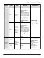
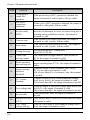
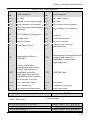
3.1.2 Description of keystroke function
On the inverter keyboard, there are nine keystrokes. In addition, the function of each
keystroke is defined as table 3-2.
41
Chapter 3 Operation
Table 3-2 Description of keystroke function
key
Name of key
Key functions
PRG
ESC
Programming
key/Escape key
Go to programming state or escape from
programming state. When in the monitoring state,
By pressing the PRG/ESC key, the keyboard will
switch from the monitoring state to programming
state. In addition, it will firstly go to the function
group menu, and then if the user press the
“ENTER”key, it will go to the function code menu,
and then go to the function parameter menu if press
the “ENTER”key again.
When in the function parameter menu, press the
“PRG/ESC” key, the keyboard will switch to the
function code menu, and then to the function group
menu, and then to the monitoring state.
When in fault state, press the “PRG/ESC” key, the
keyboard will switch from fault code display to the
function group menu. The same function is to
warning state.
ENTER
Enter key
Go to the next menu in programming state.
Save the parameter set value when in the function
parameter menu.
Increment key
(Turn right)
Digital
Encoder
-
+
+
Decrement key
(Turn left)
-
42
In programming state, number change keys changes
parameter group and parameter numbers or set
values. When in the function parameter menu, the
changeable number will blink. Press increment key,
the number will increase.
In monitoring state, if the frequency setting mode
by keyboard is effective. Turn right this key; it will
increase the setting frequency directly. And this
function is applied to the PID speed feed and PID
analog feed.
The same function as Increment key, but the
number will decrease instead of increase.
Chapter 3 Operation
key
Name of key
Key functions
>>
Shift key
In programming state, press this key can change the
blink number position.
In monitoring state, press this key to change the
monitoring object such as output frequency and
output current (4 digits).
JOG
Jog key
When the running command mode is determined by
keyboard, press the JOG key, the inverter will come
into jog running state and the green LED will light.
RUN
Run key
When the inverter is controlled by keyboard, press
the run key, the inverter will start to run and the
green LED will light after pressing RUN key.
Direction switch
key
By pressing this key, the running direction can be
switched between forward and reverse. Please see
the description of P0.05 to see the details.
Stop/Reset key
When the inverter is controlled by the keyboard,
press the “STOP/RESET” key, the inverter will
stop running.
When in fault state, the inverter will clear the fault
and return to the normal state.
STOP
RESET
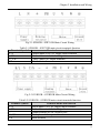
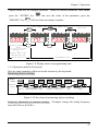
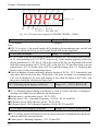
3.1.3 Description of LED digitals and indicators
On the inverter keyboard there are four digitals seven segments LEDs, 3 unit indicators,5
status indicators. The four digitals can display the monitoring object, the function
parameter values and the fault code, the warning code. The 3 unit indicators have 8
combinations, and each combination corresponds to one unit .The combinations and
their corresponding units are as the following:
Hz
r/min
A
%
m/s
V
no unit
Hz
r/min
A
%
m/s
V
Hz
Hz
r/min
A
%
m/s
V
A
Hz
r/min
A
%
m/s
V
V
ON
Hz
r/min
A
%
m/s
V
r/min
Hz
r/min
A
%
m/s
V
Hz
r/min
A
%
m/s
V
m/s
%
Hz
r/min
A
%
m/s
V
PID
OFF
Figure 3-2 Combinations of unit indicator and their means
The 5 status indicators are just above the four digitals and the mean of each indicator is
shown in table 3-3.
43
Chapter 3 Operation
Table 3-3 Description of state indicators
Mean :Indicator the state of
Indicator
Display state
inverter
RUN running state indicator
FWD running forward
indicator
REV running reverse indicator
TRIP fault indicator
REMOTE command mode
indicator
OFF
The inverter is stop
ON
The inverter is running
Blinking slowly Zero-speed running.
The inverter is running reverse
OFF
or stop
The inverter is running forward
ON
steadily.
Speed up or speed down
Blinking fast
forward
Indicates that the inverter is at
Blinking slowly stop state and the setting
direction is forward
The inverter is running forward
OFF
or stop
The inverter is running reverse
ON
steadily.
Blinking fast
Speed up or speed down reverse
Indicate that the inverter is at
Blinking slowly stop state and the setting
direction is forward
OFF
The inverter is at normal state
Blinking slowly The inverter is at abnormal state
The inverter is controlled by the
OFF
keyboard
The inverter is controlled by the
ON
terminals
The inverter is controlled by
Blinking slowly
serial communication.
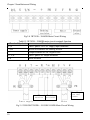
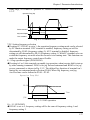
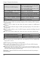
3.1.4 Display state of keyboard
The working state of this series inverter includes two states: stop state and running state.
Stop State: If there is no running command input after the inverter is power on and
initialized, or the inverter has received a stop command input, the inverter will come into
stop state.
44
Chapter 3 Operation
Running state: The inverter has received a running command and then comes into
running state.
So, the display states of keyboard include display of stop state, display of running state
and display of programming state and display of fault and warning state.
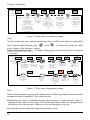
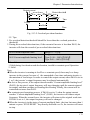
●Display of stop state
If the inverter is a stop state, the four digitals of keyboard will display the parameters
value of stop state: For example, the output frequency. See figure-3-2, and the unit
>>
indicator will indicate the unit of the parameter. Press
key, the keyboard will
cycling display the value of different monitoring objects (selected by the parameter
group PC).
●Display of running state
If the inverter got an effective running command, it will come into running state. Then
the four digitals of keyboard will display the parameters value of running state .see
example of figure 3-3-3. and the unit indicator will indicate the unit of the parameter.
>>
Press
key, the keyboard will cycling display the value of different monitoring
objects (selected by the parameter group PC).
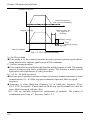
●Fault and warning state
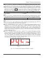
If the inverter has checked out a warning signal, it will come into warning state and
show the warning code flickeringly. See example of figure 3-3-5. If the warning signal
disappeared, the warning code will automatically disappear.
If the inverter has checked out an error, it will come into fault state and show the fault
code steadily. And the indicator TRIP will light up, see example of figure 3-3-6.
By pressing the
>>
key, user can view the parameters value of stop state; If you want
PRG
to see the details of fault information, press the ESC key, the keyboard will go to
programming state, to see the details, please see the parameter values of group PE.
STOP
RESET
key or control terminals or serial communication.
To reset the inverter, press the
If the fault signal is still exist, the keyboard will keep the fault code displaying and the
indicator TRIP lighting.
45
Chapter 3 Operation
RUN
FWD
REV
REMOTE
TRIP
RUN
FWD
REV
REMOTE
-
+
>>
JOG
RUN
RUN
FWD
REV
-
>>
STOP
RESET
RUN
REMOTE
JOG
RUN
FWD
-
+
>>
RUN
JOG
>>
STOP
RESET
RUN
-
STOP
RESET
RUN
+
JOG
ENTER
STOP
RESET
3-3-3 Display of running state
RUN is on,FWD blink fast when speed up
RUN
FWD
REV
REMOTE
TRIP
Hz
r/min
A
%
m/s
V
-
+
PRG
ESC
>>
TRIP
-
Hz
r/min
A
%
m/s
V
ENTER
3-3-4 Display of running state
RUN is on,the inverter run to the
setting frequence and FWD is ON
at steady state.
REMOTE
Hz
r/min
A
%
m/s
V
ENTER
REV REMOTE TRIP
Hz
r/min
A
%
m/s
V
PRG
ESC
REV
PRG
ESC
3-3-2 Display of stop state.
RUN is off,FWD blink slowly
TRIP
FWD
+
PRG
ESC
ENTER
3-3-1 Display of power on.
Output frequency is 0.00Hz
RUN
Hz
r/min
A
%
m/s
V
Hz
r/min
A
%
m/s
V
PRG
ESC
TRIP
+
PRG
ESC
JOG
ENTER
>>
STOP
RESET
RUN
3-3-5 Display of warning state.
The warning code is flickering
JOG
ENTER
STOP
RESET
3-3-6 Display of fault state.
The fault code is shown and TRIP is on
Figure 3-3 Display of initialization, stop, running, warning and stop of inverter
●Programming state
PRG
When in the stop, running fault or warning state, press the PRG/ESC key ESC , the
inverter will come into programming state. (If the user has set the user password,
please see chapter 5.16, description of PF.00). In programming state, there are three
display menus, see figure 3-4. They are function group menu, function parameter
number menu, and function parameter value menu, press the “ENTER” key
46
ENTER
, the
Chapter 3 Operation
display menu will be changed gradually. When in function parameter value menu,
press the “ENTER” key
“PRG/ESC” key
PRG
ESC
FWD
REV
REMOTE
TRIP
can save the value of the parameter; press the
will exit from one menu to another.
PRG
ESC
RUN
ENTER
the parameter
the parameter
group number menu ENTER code number menu
ENTER
ENTER
RUN
FWD
REV
REMOTE
Hz
r/min
A
%
m/s
V
TRIP
RUN
FWD
REV
REMOTE
Hz
r/min
A
%
m/s
V
PRG
Display parameters ESC
value
of stop state and
running state
or
display fault code
and warning code
TRIP
RUN
the parameter
value menu
FWD
REV
REMOTE
Hz
r/min
A
%
m/s
V
TRIP
Hz
r/min
A
%
m/s
V
PRG
PRG/ESC
PRG
ESC
ESC
ENTER
ENTER
monitoring state
programming state
Figure 3-4 Display menus of programming state
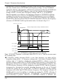
3.1.5 Operation method of keyboard
Here are some examples of how to run the inverter by the keyboard:
Monitoring object switching:
Display
of LED
Operation
of key
50.00
50.00
>>
45.0
>>
Actual output Output frequency Output
frequency before compensation current
50.00
>>
1440
1440
>>
Setting
frequency
>>
Motor
rotate speed
0.000
>>
>>
Seting
speed
Actual
length
Figure 3-5 Flow chart of monitoring object switching
Frequency adjustment at common running: (Example: change the setting frequency
from 50.00 Hz to 40.00 Hz).
47
Chapter 3 Operation
Display
of LED
0.00
50.00
Operation
of key
-
49.99
-
49.50
40.00
0.00
-
-
The maximal
Stop
3 seconds
step length trunning
later,the
can reach
keyboard will
to
automatically
1Hz.Depress
return to the
the Enter
original
key to save
monitoring
the desired
object.
value.
Keep on
output Turn left the turn left 1
turnning,
time,seting
frequency
digital
the
decrease
frequency
encoder,the
decrease step length can
keyboard will
reach
to
0.01Hz
automatically
0.10Hz,seting
come into
frequence
can
frequency setting
decrease 0.10Hz
state.Unit Hz
1
time.
will blink.And
the monitoring
object is setting
frequency
Figure 3-6 Flow chart of frequency setting
Note:
If in the monitoring state, and the monitoring object is PID rotate speed or analog PID
+
-
or left
, it can directly change the value
feed. Turn the digital encoder right
as the change of the frequency setting.
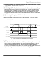
Setting the parameters value: (Example: change jog accelerate time from 6.0 second to
3.2 second)
Display
of LED
-P0-
0.00
P2.00
-P2-
PRG
Operation
+
ENTER
ENTER
ESC
of key
turn right 2 Enter
monitoring go into
into
state programming times,chose
state.display parameter parameter
code
parameter
group P2
number
group menu
menu
-P2PRG
ESC
+
turn right 1
time,chose
parameter
code
numberP2.01
Exit to
parameter
group
menu
006.0
ENTER
003.0
-
ENTER
Turn left 3
times to
chang the
number to 3
Enter into
parameter
value menu
003.2
P2.02
PRG
ESC
Exit from
the
programming
state
P2.01
003.0
+
save the
Turn right 2
changed value
times to
and exit to
change the
parameter
number to 2
code number
menu
>>
Shift to
change the
blinking
place to
right
Figure 3-7 Flow chart of parameter setting
Note:
In the function parameter menu, if the display has no flickering number, it means that the
parameter cannot be modified. The reasons maybe:
●Modifying the value is forbidden because the parameter is actual measure value, or
running record value or fixed value. The function parameter cannot be changed when
the inverter is at running state. However, it can be changed at stop state.
●So stop the inverter and then change the parameter value.
48
Chapter 3 Operation
●The inverter parameters are protected. If function parameter value PF.01=1 or 2, the
parameters are forbidden to be changed. This parameter protection function is to avoid
operation mistake. To change the protection parameters, change value of function code
PF.01 to zero, then all the parameters can be changed.
3.2 Run command mode select
The run command modes determine the methods of the inverter running and stop. The
inverter has three run command modes:
●Run command from the keyboard: press the key
inverter.
RUN
,
STOP
RESET
,
to control the
●Run command from the control circuit terminals: by using the terminal defined as
FWD,REV,COM(2-wire control mode): FWD, REV, Xi( 3-wire control mode )
to control the inverter.
●Run command from serial communication: Use a PC or PLC to control the inverter to
run or stop.
Change P0.04 to select serial communication mode. The default setting is Keyboard
control mode (The default value P0.04 is 0), If terminal control mode is needed,
STOP
RESET
please change the value to 1 or 2. If we want to keep the “STOP/RESET” key
active in terminal control mode, we must set the value to 2.
If we need to control the inverter by PC or PLC serial communication, we should set
P0.04 to 3 or 4.
If the indicator REMOTE is off, it tells that the inverter is controlled by the keyboard .If
the indicator REMOTE is on, it tells that the inverter is controlled by the terminals. In
addition, if the indicator is flickering, it tells the inverter is controlled by serial
communication.
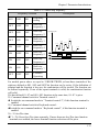
3.3 Trial Operation
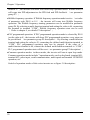
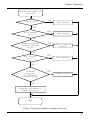
3.3.1 Operation mode of inverter
This series of inverter have five operation modes: JOG operation, PID closed loop
operation, Wobble frequency operation, PLC programmed operation and common
operation.
●JOG operation: If the inverter received a jog operation command (for example,
JOG
key) at a stop state, the inverter will jog running at the jog frequency
press
reference set by function code P2.00~P2.02.
●PID closed loop operation: If PID close loop operation is selected by P0.01 (set the
49
Chapter 3 Operation
value to 9), the inverter will chose PID closed loop operation mode. In other word, it
will come into PID adjustment as the PID feed and PID feedback. (see parameter
group P7);
●Wobble frequency operation: If Wobble frequency operation mode is active (set value
of parameter code P0.01 to 10), the inverter will come into Wobble frequency
operation. The Wobble frequency running parameters can be modified in parameter
group P6. By selecting a multi-function terminal and setting the value to 46, connecting
the terminal to terminal “COM”, Wobble frequency operation state can be reset
( Refer to chapter 4, see details P3 description);
●PLC programmed operation: If PLC programmed operation mode is selected by P0.01
(set the value to 8), the inverter will chose PLC programmed operation: every steps can
be pre-defined (see parameter group P5 description). By selecting a multi-function
terminal and setting the value to 43, connecting the defined multi-function terminal to
“COM”, PLC programmed operation state can be stopped. If the value of a
multi-function terminal is 44, connect the defined multi-function terminal to “COM”,
PLC programmed operation state will be reset(see parameter group P3 description);
●Common operation modes: in these modes, the inverter will run at open loop mode.
Common operation modes include 7 operation modes, such as keyboard, terminal AI1,
terminal AI2, pulse input, serial communication, multi-speed and terminal UP/DOWN
operation, etc.
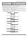
Switch of operation modes of this series inverter are as figure 3-8 description:
50
Chapter 3 Operation
Operation mode of
inverter
JOG active
YES
JOG running
NO
PID termianl
active
YES
PID running
NO
Wobble frequency
running terminal
active
YES
Wobble frequency
running
NO
PLC termianl
active
YES
PLC running
NO
Termianl
function:
FC frequency
setting active
YES
Common running
NO
Running according to
P0.01 selection
END
Figure 3-8 Operation modes switching of inverter
51
Chapter 3 Operation
3.3.2 Before operation checkpoints
To ensure safety, prior to initial operation, disconnect the machine coupling so that the
motor is isolated from the machine. If initial operation must be performed while the
motor is still coupled to the machine, use great care to avoid potentially hazardous
conditions. Check the following items before a trial run:
● Wiring and terminal connections are proper.
●Wire clippings and other debris removed from the unit.
● Screws are securely tightened.
●Motor is securely mounted.
●All items are correctly grounded.
● Keyboard Display at Power-Up.
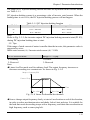
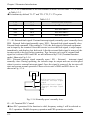
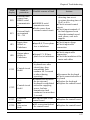
3.3.3 Operation checkpoints
●Motor rotates smoothly.
● Motor rotates in the correct direction.
●Motor has neither abnormal vibration nor noise.
● Acceleration and deceleration are smooth.
●Unit is not overloaded.
● Status indicator and keyboard display are correct.
3.3.4 A trial run
Please wiring the main circuit and control circuit strictly according to the technology
requirement provided by the user manual when the inverter is ready for operation, turn
ON the power supply. Verify that the inverter powers up properly. If any problems are
detected, turn OFF the power supply immediately.
When the keyboard displays the output frequency, the inverter is initialized. If the
keyboard is not connected right, the keyboard will display the fault code “CCF2” after 5
seconds. Please connect the keyboard again.
Operation process of power up the inverter is as the following:
52
Chapter 3 Operation
Start
wiring as the
requirement stated
in this manual
NO
wiring is right.
YES
NO
the input
voltate is right
YES
Power ON
see output frequency
monitor:0.00Hz
NO
YES
heard the sound of
contactor indraft?
NO
Display fault
code"CCF2"or no
disolay
Power on failed
YES
POWER
ON sucsessful
Disconnect the power
input air switch.
Check the reason
Figure 3-9 Flow chart of the inverter initialization
53
Chapter 3 Operation
3.4 Commissioning of keyboard
Assume that the inverter need to run forward at 30.00 Hz at first, then run reverse at the
same frequency,
Using the keyboard can take the following steps to realize the task:
A typical operation pattern using the keyboard:
a
b
c
e
d
Forward
30.00Hz
P ower
on
Frequency Forward Run
Set t ing
Reverse
Reverse Run
S t op
30.00Hz
Figure 3-10 Operation sequence by keyboard
Running and stop operation:
Display
of LED
-P0-
0.00
Operation
of key
PRG
ESC
P0.00 50.00 30.00
ENTER
ENTER
monitoring Enter into
Enter
Enter
state
into
programming
into
state.display parameter parameter
value
parameter
code
menu
group menu
number
menu
-
P0.01 -P0ENTER
PRG
ESC
0.00
PRG
ESC
30.00
30.00
RUN
0.00
STOP
RESET
Turn left save the Exit to
Exit to
Output
Running
Running
3 times changed parameter monitoring forward.
frequency
reverse.
to chang value and group
state FWD LED ON. REV LED ON.
will
exit to
the
menu
REV LED OFF. FWD LED OFF. decrease
number parameter
to 0.The
Output
code
from
inverter
frequency
5 to 3 number
will stop
will go up
menu
to setting
frequency.
Figure 3-11 Flow chart of running and stop operation
Jog running operation: (Assume that the current run command mode is keyboard and
the inverter is at stop state.)
Display
of LED
Operation
of key
0.00
0.50
JOG
output
frequency
monitor
display
depress
jog key
and keep
on
5.00
The inverter goes into
running state and the
output frequecy goes up
gradually to the jogging
setting frequency
0.00
JOG
Release
the key
Output frequency
will drop gradually
untill the inverter
is stop
Figure 3-12 Example of Jog running
54
stop
Chapter 3 Operation
3.5 Operation of Control Circuit Terminal
Assume that the inverter needs to run forward at 30.00 Hz at first, and then stop by
terminal, using the keyboard can take the following steps to realize the task:
Sequence of terminal operation:
a
b
d
c
Forward
30.00Hz
Power
on
Frequency
setting
Running
Stop
Figure 3-13 Sequence of terminal operation
Operation steps:
Display
of LED
0.00
Operation
of key
PRG
PRG
Close
PRG
ENTER
ENTER
ENTER X1-COM
ESC
ESC
ESC
go to
monitoring go from
change save the return to return to
Close
state
parameter parameter the
setting parameter monitoring between
value
group
control circuit
value group menu state
nuber
menu
terminals FOR
menu to
and
from
and COM to
parameter
5 to 3 return to
perform
code
parameter
forward run
number
code
menu
number
menu
-P0-
P0.00 50.00
30.00 P0.01 -P0-
0.00
30.00
Open
X1-COM
open
between
control
circuit
terminals
FOR and
COM to
stop
operation.
Figure 3-14 Flow chart of running and stop operation by terminal
55
Chapter 4 Parameter Index
Chapter 4 Parameter Index
Attention:
“○”means that the parameters can be changed during inverter running and stop state;
“×”means that the parameters cannot be changed during running;
“*” means that the actually measured value or fixed parameters cannot be changed;
“-” means that the parameters can be only set by the manufacturer and cannot be
changed by the user.
P0: Basic function
Function
code
Function
Name
LCD
Display
P0.00
Reference
frequency
Reference
frequency
P0.01
Frequency
setting 1
Frequency
setting 1
P0.02
Frequency
setting 2
Frequency
setting 2
56
Range of settings
0 ~ Maximum
frequency
0: NULL
1: Set by keyboard
digital encoder
2: Terminal AI1
3: Terminal AI2
4: Pulse input
5: Serial
communication
6: MS
(Multi-step)
Speed
7: Terminal
UP/DOWN
8: PLC
9: PID
10: Wobble
frequency
operating
Ibid, 0~6
Default
0.00Hz
Change
MODBUS
Address
○
0100
1
×
0101
0
×
0102
Chapter 4 Parameter Index
Function
code
Function
Name
LCD
Display
P0.03
Frequency
setting
selection
Frequency
setting
selection
P0.04
Run
command
mode
selection
Run
command
mode
selection
Range of settings
0: Frequency
setting 1
1: Terminal
Selection
2: Frequency
setting 1+
Frequency
setting 2
3: | Frequency
setting 1Frequency
setting 2 |
4: Min
(Frequency
setting 1,
Frequency
setting 2)
5: Max
(Frequency
setting 1,
Frequency
setting 2)
0: Keyboard
control
1: Terminal
control 1(STOP
invalid)
2: Terminal
control
2(STOP valid)
3: Serial
communication
1(STOP
invalid)
4: Serial
communication
2(STOP valid)
5: Terminal
control 3
(STOP and
JOG invalid)
MODBUS
Address
Default
Change
0
×
0103
0
×
0104
57
Chapter 4 Parameter Index
Function
code
Function
Name
LCD
Display
P0.05
Keyboard
direction
setting
Keyboard
direction
setting
P0.06
Basic
Frequency
Basic
Frequency
P0.07
Maximum
output
frequency
Maximum
frequency
P0.08
Upper limit
frequency
Upper limit
frequency
Lower
limit
frequency
Maximum
output
voltage
Lower
limit
frequency
Maxim
output
voltage
P0.09
P0.10
58
Range of settings
MODBUS
Address
Default
Change
0
○
0105
50.00Hz
×
0106
50.00Hz
×
0107
50.00Hz
×
0108
0.00 ~ Upper
limit frequency
0.00Hz
×
0109
110~480V
Rated
inverter
×
010A
0: Forward
1: Reverse
S2R4GB~
3004GB :
0.10~650.0Hz
35R5GB/37R5PB
or above:
0.10~400.0Hz
S2R4GB~
3004GB :
MAX
[50.00Hz,
Upper limit
frequency,
Reference
frequency] ~
650.0Hz
35R5GB/37R5PB
or above:
MAX[50.00Hz,
Upper limit
frequency,
Reference
frequency] ~
400.0Hz
MAX[Lower limit
frequency ]~
Max frequency
Chapter 4 Parameter Index
Function
code
Function
Name
LCD
Display
P0.11
Step length
of digital
encoder
regulation
Step length
of digital
encoder
regulation
P0.12
V/F curves
setting
V/F curves
setting
V/F
frequency
value F1
V/F
voltage
value V1
V/F
frequency
value F2
V/F
voltage
value V2
V/F
frequency
value F3
V/F
frequency
value F1
V/F
voltage
value V1
V/F
frequency
value F2
V/F
voltage
value V2
V/F
frequency
value F3
P0.13
P0.14
P0.15
P0.16
P0.17
Range of settings
MODBUS
Address
Default
Change
0
×
010B
0
×
010C
0.0~P0.15
10.00Hz
×
010D
0.0~100.0%
20.0%
×
010E
P0.13~P0.17
25.00Hz
×
010F
0.0~100.0%
50.0%
×
0110
P0.15~P0.06
40.00Hz
×
0111
0: Digital encoder
integral
regulation
1~250*
(0.01Hz/1rpm):
Step
length of digital
encoder
regulation
0: Constant torque
curve
1:
Torque-reducin
g curve1(2.0)
2:
Torque-reducin
g curve2(1.5)
3:
Torque-reducin
g curve3(1.2)
4: V/f Custom
(According to
function code
P0.13~P0.18 )
59
Chapter 4 Parameter Index
Function
code
P0.18
Function
Name
V/F
voltage
value V3
LCD
Display
V/F
voltage
value V3
Default
0~100.0%
80.0%
×
0112
3004G
B or
below:
4.0%
35R5G
B/37R5
PB or
above:
0.0%
○
0113
○
0114
○
0115
○
0116
P0.19
Control
mode
Control
mode
0.0: Magnetic flux
vector
control
0.1~30.0%:
Manual
torque boost
P0.20
Cut-off
point used
for manual
torque
boost
Cut-off
point used
for boost
0.00~50.00Hz
16.67Hz
3132G/3160P or
below:
0.1~3600s
3160G/3185P or
above :
1.0~3600s
3022G/
3030P
or
below:
60s
3030G/
3037P
or
over :
20.0s
P0.21
Acc time1
Acc time1
P0.22
Dec time1
Dec time1
60
MODBUS
Address
Range of settings
Change
Chapter 4 Parameter Index
P1: Start/Stop Control
Function
code
Range of settings
Default
Change
MODBUS
Address
Starting
mode
0: Start directly
1: Brake first and
then start at start
frequency
2: Start after speed
tracking (the
mode is only valid
for the motor of
35R5GB/37R5PB
or above)
Note: the startup
includes power on,
power recovery after
an instantaneous off,
external fault reset,
restart after coast to
stop.
0
○
0200
Starting
frequency
0.10~60.00Hz
0.50Hz
○
0201
Starting
holding
time
0.0~10.0s
0.0s
○
0202
P1.03
DC
injection
braking
current at
start
Brake
current at
start
Type G: 0.0~
100.0% of inverter
rated current
Type P: 0.0~80.0%
of inverter rated
current
0.0%
○
0203
P1.04
DC
injection
braking
time at
start
Brake
time at
start
0.0~30.0s
0.0s
○
0204
P1.05
Acc/Dec
mode
Acc/Dec
mode
0: Linearity
1: S-curve
2: (Reserved)
3: (Reserved)
0
○
0205
P1.00
P1.01
P1.02
Function
Name
Starting
mode
Starting
frequenc
y
Starting
frequenc
y holding
time
LCD
Display
61
Chapter 4 Parameter Index
Function
code
P1.06
P1.07
P1.08
P1.09
P1.10
Function
Name
LCD
Display
Time of
S-curve
initial
Time of
S-curve
rising
Time of
S-curve
initial
Time of
S-curve
rising
Stop
mode
Stop
mode
DC
injection
braking
frequenc
y at stop
DC
injection
braking
waiting
time at
stop
DC
injection
braking
frequency
at stop
DC
injection
braking
waiting
time at
stop
Default
Change
MODBUS
Address
20.0%
○
0206
60.0%
○
0207
0
×
0208
0.00Hz
○
0209
0.00~10.00s
0.00s
○
020A
0.0%
○
020B
0.0s
○
020C
1
×
020D
Range of settings
10.0~50.0%
(Acc/Dec Time)
P1.06+P1.07≤90%
10.0~80.0%
(Acc/Dec Time)
P1.06+P1.07≤90%
0: Deceleration to
stop
1: Coast to stop
2: Dec +DC braking
0.00~
MIN(50.00Hz,
Frequency upper
limit)
P1.11
DC
braking
current at
stop
DC
injection
braking
current at
stop
This value depends
on the inverter model
Type G: 0.0~
100.0% (inverter
rated current)
Type P: 0.0~80.0%
(inverter rated
current)
P1.12
DC
braking
time at
stop
Braking
time at
stop
0.0~30.0s
P1.13
Dynamic
braking
selection
Dynamic
braking
selection
0: Dynamic braking
is disabled
1: Dynamic braking
is enabled
62
Chapter 4 Parameter Index
Function
code
Function
Name
Brake
voltage
level
setting
(3004GB
or below)
LCD
Display
Brake
voltage
level
setting
P1.14
Brake
utility rate
(35R5G
B/37R5P
B or
above)
P1.15
P1.16
Trip-free
treatment
Trip-free
time
Brake utility
rate
Trip-free
treatment
Trip-free
time
Range of settings
360~750V
0.0~100.0%
Note: Build-in is
active only for the
model of inverter of
15kW or below of
this series;
Dynamic braking
takes effect
automatically during
deceleration
0:once trip-free,
report Uu1 fault
1:In trip-free time
give
Uu alarm,
otherwise
report Uu1 fault
2:once trip-free, give
Uu alarm
0.5~10.0s
Change
MODBUS
Address
×
020E
0
×
020B
This
value
depend
s on the
inverter
model.
×
0210
Default
Change
MODBUS
Address
5.00Hz
○
0300
Default
Singlephase:
380V
Three-p
hases:
700V
100.0%
P2: Auxiliary Operation
Function
code
Function
Name
P2.00
Jog
frequency
LCD Display
Jog
frequency
Range of
settings
0.10 ~ Upper
limit
frequency
63
Chapter 4 Parameter Index
Range of
settings
3132G/3160P
or below:
0.1~3600s
3160G/3185P
or above:
1.0~3600s
3132G/3160P
or below:
0.0~3600s
3160G/3185P
or above:
0, 1.0~3600s
Function
code
Function
Name
LCD Display
Change
MODBUS
Address
P2.01
Acc time of
Jog
Acc time of
Jog
○
0301
P2.02
Dec time of
Jog
Dec time of
Jog
○
0302
P2.03
Switching
time
between run
forward and
reverse
Switching
time
between run
forward and
reverse
0.0~3600s
0.0s
○
0303
P2.04
Frequency
lower limit
deal mode
Frequency
lower limit
deal mode
0: Running at
frequency
Lower limit
1: Zero-speed
running
0
×
0304
P2.05
Frequency
departure
setting
Frequency
departure
0.00-2.50Hz
0.00Hz
○
0305
×
0306
Default
3022G/
3030P
or
below:
6.0s
3030G/
3037P
or
above:
20.0s
P2.06
Carrier
frequency
Carrier
frequency
This
value
depends on the
inverter model
This
value
depend
s on the
inverter
model
P2.07
Jump
frequency 1
Jump
frequency 1
0.00~Max
frequency
0.00Hz
×
0307
P2.08
Jump
frequency 2
Jump
frequency 2
0.00~Max
frequency
0.00Hz
×
0308
64
Chapter 4 Parameter Index
Function
code
Function
Name
LCD Display
Range of
settings
Default
Change
MODBUS
Address
P2.09
Jump
frequency 3
Jump
frequency 3
0.00~Max
frequency
0.00Hz
×
0309
P2.10
Jump
frequency
bandwidth
Jump
frequency
bandwidth
0.00~15.00Hz
0.00Hz
×
030A
Multi-step
frequency 1
Multi-step
frequency 2
Multi-step
frequency 3
Multi-step
frequency 4
Multi-step
frequency 5
Multi-step
frequency 6
Multi-step
frequency 7
Multi-step
frequency 1
Multi-step
frequency 2
Multi-step
frequency 3
Multi-step
frequency 4
Multi-step
frequency 5
Multi-step
frequency 6
Multi-step
frequency 7
0.00
~
Maximum
frequency
5.00 Hz
10.00
Hz
15.00
Hz
20.00
Hz
30.00
Hz
40.00
Hz
50.00
Hz
P2.18
Acc time 2
Acc time2
P2.19
Dec time2
Dec time2
P2.20
Acc time3
Acc time3
P2.21
Dec time3
Dec time3
P2.22
Acc time4
Acc time4
P2.23
Dec time4
Dec time4
P2.24
Fan control
mode
Fan control
mode
P2.25
Wiring
direction of
motor
Motor
wiring
P2.11
P2.12
P2.13
P2.14
P2.15
P2.16
P2.17
3132G/3160P
or below:
0.1~3600s
3160G/3185P
or above:
1.0~3600s
0: Automatic
mode
1: Run always
in power.
0:
Positive
sequence
1:
Inverted
sequence
030B
030C
030D
○
030E
030F
0310
0311
3022G/
3030P
or
below:
6.0s
3030G/
3037P
or
above:
20.0s
○
0
×
0318
0
×
0319
0312
0313
0314
0315
0316
0317
65
Chapter 4 Parameter Index
Function
code
P2.26
66
Function
Name
Prohibit
reverse
operation
LCD Display
Prohibit
reverse
operation
Range of
settings
0: Reverse
operation
enabled
1: Reverse
operation
disabled
Default
Change
MODBUS
Address
0
×
031A
Chapter 4 Parameter Index
P3:I/O Terminal control
This page only for 3004GB and below
Function
code
Function
Name
LCD
Display
Range of settings
P3.00
Terminal
function
mode
Terminal
function
mode
Terminal
X1
function
P3.01
Multi-fun
ction
input
selection
Terminal
X1
Default
Change
MODBUS
Address
0: Close valid
1: Open valid
(Normally open
/close is not
limited.)
0
×
0400
0: NULL, No defined
1: FWD: Running
Forward
2: REV: Running
Reverse
3: RUN
4: F/R running
direction
5: HLD self-hold
selection
6: RST reset
7: FC Setting
frequency selection
8: FJOG(JOG FWD)
9: RJOG(JOG REV)
10: UP
11:DOWN
12: UP/DOWN Reset
13: FRE
Coast-to-stop
14: Forced outage
(According to Dec
time4) 15: DC
injection braking
16: Acc/Dec prohibit
17: Inverter running
prohibit
18: S1 Multi-step
Speed 1
19: S2 Multi-step
Speed 2
20: S3 Multi-step
Speed 3
21: S4 Multi-step
Speed 4
1
×
0401
67
Chapter 4 Parameter Index
This page only for 3004GB and below
Function
code
P3.02
68
Function
Name
Multi-fun
ction
input
selection
Terminal
X2
LCD
Display
Range of settings
Default
Change
MODBUS
Address
Terminal
X2
function
22: S5 Multi-step
Speed 5
23: S6 Multi-step
Speed6
24: S7 Multi-step
Speed7
25: Command
channel switch to
Terminal control 2
26: SS1 Multi-step
Speed
27: SS2 Multi-step
Speed
28: SS3 Multi-step
Speed
29: Command
channel switch to
Keyboard control
30: T1 Acc/Dec time1
31: T2 Acc/Dec time1
32: T3 Acc/Dec time1
33: T4 Acc/Dec time1
34: TT1 Acc/Dec
time1
35: TT2 Acc/Dec
time1
36: Force stop
normally close
37: EH0: External
fault signal
normally open
38: EH1: External
fault signal
normally close
39: EI0: External
interrupt signal
normally open
2
×
0402
Chapter 4 Parameter Index
This page only for 3004GB and below
Function
code
Function
Name
LCD
Display
P3.03
Multi-fun
ction
input
selection
Terminal
X3
Terminal
X3
function
P3.04
Multi-fun
ction
input
selection
Terminal
X4
Terminal
X4
function
Range of settings
40: EI1: External
interrupt signal
normally close
41: Reserved
42: Start PLC
operation
43: Pause the PLC
operating
44: Reset PLC stop
status
45: Start Wobble
frequency
operating
46: Reset the Wobble
frequency
operating status
47: Start PID
operation
48:Reserved
49: Timing drive
input
50: Counter trig
signal input
51: Counter clear
52: Actual Length
clear
53: Timing units
chose
0~53: Ibid
54: PUL: Pulse input
( If have 2 signals
input, follow X4)
55: Single-phase
speed measuring
input ( If have 2
signals input,
follow X4)
Default
Change
MODBUS
Address
37
×
0403
0
×
0407
69
Chapter 4 Parameter Index
This page only for 3004GB and below
Function
code
P3.05
P3.06
P3.07
P3.08
P3.09
70
Function
Name
LCD
Display
Multi-fun
ction
input
selection
Terminal
X5
Reserved
Reserved
Reserved
Reserved
Reserved
Reserved
Operatio
n mode
setup
Operatio
n mode
setup
Terminal
X5
function
Range of settings
56: Speed measuring
input SM1(only
for X4)
57: Speed measuring
input SM2(only
for X5)
Reserved
Reserved
Reserved
0: 2-wire control
mode1
1: 2-wire control
mode 2
2: 3-wire control
mode 1-self-hold
function (added
any terminal of
X1-X5)
3: 3-wire control
mode 2-self-hold
function (added
any terminal of
X1-X5)
Default
Change
MODBUS
Address
0
×
0408
0
0
0
×
×
×
0406
0407
0408
0
×
0409
Chapter 4 Parameter Index
This page only for 35R5GB/37R5PB and over
Function
code
Function
Name
LCD
Display
Range of settings
Default
Change
MODBUS
Address
P3.00
Terminal
function
mode
Termin
al
functio
n mode
0: Close valid
1: Open valid
(Normally open
/close is not limited.)
0
×
0400
1
×
0401
2
×
0402
P3.01
Multi-fu
nction
input
selection
Terminal
X1
Termin
al X1
functio
n
P3.02
Multi-fu
nction
input
selection
Terminal
X2
Termin
al X2
functio
n
0:NULL, No defined
1: FWD: Running
Forward
2:
REV:
Running
Reverse
3: RUN
4: F/R running direction
5:
HLD
self-hold
selection
6: RST reset
7: FC Setting frequency
selection
8: FJOG(JOG FWD)
9: RJOG(JOG REV)
10: UP
11:DOWN
12: UP/DOWN Reset
13: FRE Coast-to-stop
14: Forced outage
(According to Dec
time4)
15:
DC
injection
braking
16: Acc/Dec prohibit
17: Inverter running
prohibit
18: S1 Multi-step
Speed 1
19: S2 Multi-step Speed
2
20: S3 Multi-step Speed
3
21: S4 Multi-step Speed
4
71
Chapter 4 Parameter Index
This page only for 35R5GB/37R5PB and over
Function
code
Function
Name
LCD
Display
P3.03
Multi-fu
nction
input
selection
Terminal
X3
Termin
al X3
functio
n
P3.04
Multi-fu
nction
input
selection
Terminal
X4
Termin
al X4
functio
n
72
Range of settings
22: S5 Multi-step Speed
5
23:
S6
Multi-step
Speed6
24:
S7
Multi-step
Speed7
25: Command channel
switch to Terminal
control 2
26: SS1 Multi-step
Speed
27: SS2 Multi-step
Speed
28: SS3 Multi-step
Speed
29: Command channel
switch to Keyboard
control
30: T1 Acc/Dec time1
31: T2 Acc/Dec time1
32: T3 Acc/Dec time1
33: T4 Acc/Dec time1
34: TT1 Acc/Dec time1
35: TT2 Acc/Dec time1
36: Forced outage
normally close
37: EH0: External fault
signal normally open
38: EH1: External fault
signal normally close
39:
EI0:
External
interrupt
signal
normally open
40:
EI1:
External
interrupt
signal
normally close
41: Reserved
42: Start PLC operation
Default
Change
MODBUS
Address
37
×
0403
26
×
0404
Chapter 4 Parameter Index
This page only for 35R5GB/37R5PB and over
Function
code
Function
Name
LCD
Display
P3.05
Multi-fu
nction
input
selection
Terminal
X5
Termin
al X5
functio
n
P3.06
Multi-fu
nction
input
selection
Terminal
X6
Termin
al X6
functio
n
P3.07
Multi-fu
nction
input
selection
Terminal
X7
Termin
al X7
functio
n
P3.08
Multi-fu
nction
input
selection
Terminal
X8
Termin
al X8
functio
n
Range of settings
43: Pause the PLC
operating
44: Reset PLC stop
status
45:
Start
Wobble
frequency operating
25~45: Ibid
46: Reset the Wobble
frequency operating
status
47: Start PID operation
48:Reserved
49: Timing drive input
50: Counter trig signal
input
51: Counter clear
52: Actual Length clear
53: Timing units chose
0~53: Ibid
54: PUL: Pulse input
( If have 2 signals
input, follow X7)
55: Single-phase speed
measuring input ( If
have 2 signals
input, follow X7)
56: Speed measuring
input SM1(only for
X7)
57: Speed measuring
input SM2(only for
X8)
Default
Change
MODBUS
Address
27
×
0405
28
×
0406
0
×
0407
0
×
0408
73
Chapter 4 Parameter Index
This page only for 35R5GB/37R5PB and over
Function
code
LCD
Display
Range of settings
Default
Change
MODBUS
Address
P3.09
Operatio
n mode
setup
Operati
on
mode
setup
0: 2-wire control mode1
1: 2-wire control mode
2
2: 3-wire control mode
1-self-hold function
(added any terminal
of X1-X8)
3: 3-wire control mode
2-self-hold function
(added any terminal
of X1-X8)
0
×
0409
Function
code
Function
Name
LCD
Display
Range of settings
Default
Change
MODBUS
Address
P3.10
Terminal
UP/DN
rate
UP/DN
rate
0.01~99.99Hz/s
1.00Hz
/s
○
040A
P3.11
UP/DN
reference
amplitud
e
UP/DN
referen
ce
amplitu
de
0.00~Frequency upper
limit
10.00H
z
○
040B
UP/DO
WN
Save
selectio
n
0: Receive STOP,
UP/DN reference
reset to zero
1: Receive STOP,
UP/DN reference not
reset to zero, and not
save when power
loss
2: Receive STOP,
UP/DN reference not
reset to zero, and
save when power
loss; If P0.01is set to
1, P0.00 will be
saved when power
loss.
1
×
040C
P3.12
74
Function
Name
Digital
frequenc
y
UP/DO
WN save
selection
Chapter 4 Parameter Index
Function
code
Function
Name
LCD
Display
P3.13
Define
Function
s of
terminal
DO
Functio
ns of
termina
l DO
P3.14
Terminal
Y1
function
definitio
n
Termin
al Y1
functio
n
Range of settings
0: NULL
1: RUN
2: FAR: Frequency
arriving
3: FDT: Frequency
detection threshold
4: FDTH: Frequency
upper limit arriving
5: FDTL: Frequency
lower limit arriving
6: Upper and lower
limits of Wobble
frequency
7: Zero-speed running
8: Completion of
simple PLC
operation
9: PLC cycle
completion
indication
10: Inverter ready
(RDY)
11: Coast-to-stop
12: Auto restart
13: Timing Arriving
14: Counting value
arriving output
15: Preset operating
time arriving out
16: Torque arriving
detection threshold
17: CL: Current Limit
18: Over-voltage stall
19: Inverter fails
20: External fault stop
(EXT)
21: Uu1: Under
voltage lock-up
22: Reserved
Default
Change
MODBUS
Address
0
×
040D
1
×
040E
75
Chapter 4 Parameter Index
Function
code
Function
Name
LCD
Display
P3.15
Terminal
Y2
function
definitio
n
Termin
al Y2
functio
n
P3.16
Output
functions
selection
of relay 1
(TA/TB/
TC)
Relay
output
76
Range of settings
23: OLP: Overload
signal
24: Analog signals1
abnormal
25: Analog signals2
abnormal
26: STEP:
Programming
Running steps (only
active to
DO\Y1\Y2, and
need to set P3.13,
P3.14, P3.15 the
same value as 26)
27: Fault type output
(Only active to
DO\Y1\Y2, and
need to set P3.13,
P3.14, P3.15 the
same value as 27)
28: Fixed-length
arrived, output a
high level signals
29: Standby
30: Zero-speed running
Note: Function code
P3.14 and P3.15 can’t
be set, while 26
and27’s
output functions are
reserved
Default
Change
MODBUS
Address
2
×
040F
19
×
0410
Chapter 4 Parameter Index
Function
code
Function
Name
P3.17
Fixed
length
reaches
the
terminal
output
hold time
(3004GB
or below)
Output
functions
selection
of relay 2
(BRA/B
RB/BRC
)
(35R5G
B/37R5P
B or
above)
LCD
Display
Fixed
length
output
remains
Range of settings
0.0~3.0s
Default
Change
MODBUS
Address
×
0411
1.0s
Relay
output
0~30:the same as
P3.16
FAR
width
0.00~10.00Hz
2.50Hz
○
0412
50.00Hz
○
0413
1.00Hz
○
0414
P3.18
FAR
detection
width
P3.19
Frequenc
y
detection
threshold
(FDT)
level
FDT
level
3004GB or below :
0.00~650.0Hz
35R5GB/37R5PB or
above:
0.00~400.0Hz
P3.20
Frequenc
y
detection
threshold
(FDT)
lag
FDT
lag
0.00~10.00Hz
0
77
Chapter 4 Parameter Index
Function
code
Function
Name
LCD
Display
Default
Change
MODBUS
Address
P3.21
Frequenc
y upper
limit
arriving
output
delay
time
Freque
ncy
upper
limit
output
delay
0.0~100.0s
0.0s
○
0415
P3.22
Frequenc
y lower
limit
arriving
output
delay
time
Freque
ncy
lower
limit
output
delay
0.0~100.0s
0.0s
○
0416
P3.23
Torque
detection
reference
Torque
detectio
n
referen
ce
0.0~200.0%
100.0%
○
0417
P3.24
Preset
Count
value
Preset
Count
value
0~9999
0
○
0418
P3.25
Preset
Timing
arriving
Preset
Timing
arriving
0.0~6553.0s
0.0s
○
0419
P3.26
Preset
operating
time
Preset
operati
ng time
0~65530h
65530h
×
041A
78
Range of settings
Chapter 4 Parameter Index
P4: Analog and Pulse Function
Function
code
P4.00
P4.01
P4.02
P4.03
P4.04
P4.05
Function
Name
Analog
Nonlinea
r
Selection
Min
analog
value
Input 1
(AI1
Terminal
)
Physical
value 1
correspo
nding to
Min
analog
value
Input
Max
analog
value
Input 1
(AI1)
Physical
value 1
correspo
nding to
Max
analog
value
Input
Analog
input
filter
time
constant
1 (AI1
Terminal
)
LCD
Display
Range of settings
Default
Change
MODBUS
Address
0
×
0500
Analog
Nonlinear
Selection
0:None 1:AI1
2:AI2 3: Pulse
Min analog
value 1
0.00~P4.03
0.10V
○
0501
Physical
value 1
correspond
ing to Min
0.0~100.0%
0.0%
○
0502
Max
analog
value1
P4.01~10.00V
10.00V
○
0503
physical
value 1
correspond
ing to Max
0.0~100.0%
100.0%
○
0504
Analog
input filter
1
0.01~50.00s
0.05s
○
0505
79
Chapter 4 Parameter Index
Function
code
Function
Name
LCD
Display
Default
Change
MODBUS
Address
P4.06
Min
analog
value
Input 2
(AI2
Terminal
)
Min analog
value 2
0.00~P4.08
0.10V
○
0506
P4.07
Physical
value 2
correspo
nding to
Min
analog
value
Input
physical
value 2
correspond
ing to Min
0.0~100.0%
0.0%
○
0507
P4.08
Max
analog
value
Input 2
(AI2)
Max
analog
value 2
P4.06~10.00V
10.00V
○
0508
P4.09
Physical
value 2
correspo
nding to
Max
analog
value
Input
physical
value 2
correspond
ing to Max
0.0~100.0%
100.0%
○
0509
P4.10
Analog
input
filter
time
constant
2 (AI2
Terminal
)
Analog
input filter
2
0.01~50.00s
0.05s
○
050A
80
Range of settings
Chapter 4 Parameter Index
Function
code
P4.11
P4.12
P4.13
P4.14
P4.15
Function
Name
Min
pulse
value
Input 3
(pulse
input
Terminal
)
Physical
value 3
correspo
nding to
Min
pulse
value
Input
Max
pulse
value
Input 3
(pulse
Input
Terminal
)
Physical
value 3
correspo
nding to
Max
pulse
value
Input
Pulse
input
filter
time
constant
3 (pulse
Input
Terminal
)
LCD
Display
Range of settings
Default
Change
MODBUS
Address
Min pulse
value
Input 3
(pulse
Terminal)
0.00~P4.13
0.00k
○
050B
physical
value 3
correspond
ing to Min
pulse value
Input
0.0~100.0%
0.0%
○
050C
Max pulse
value Input
3(pulse
Terminal)
P4.11~50.00k
50.00k
○
050D
Physical
value 3
correspond
ing to Max
pulse value
Input
0.0~100.0%
100.0%
○
050E
Pulse input
filter 3
0.01~50.00s
0.05s
○
050F
81
Chapter 4 Parameter Index
Function
code
Function
Name
LCD
Display
P4.16
PG Pulse
Range
PG Pulse
Range
P4.17
AO1
function
definitio
n
AO1termin
al output
P4.18
AO2
function
definitio
n
AO2termin
al output
P4.19
DO
output
DO output
82
Range of settings
1~9999
0: Output frequency
before
compensation
(0~Max
Frequency)
1: Output current
(0~2* inverter
rated current)
2: Output voltage
(0~Max Voltage)
3: PID feed
(0~10V)
4: PID feedback
(0~10V)
5: Adjust signals
(5V)
6: Output torque
(0~2*inverter
rated torque)
7: Output power
(0~2*Inverter
rated power)
8: Bus voltage
(0~1000V)
9: AI1 (0~10V)
10: AI2
(0~10V/0~20mA
)
11: Output
frequency after
compensation
(0~maximum
frequency)
12~14: Reserved
15: NULL
Default
Change
MODBUS
Address
1024
○
0510
r
×
0511
1
×
0512
11
×
0513
Chapter 4 Parameter Index
Function
code
Function
Name
LCD
Display
Range of settings
P4.20
AO1
output
range
selection
AO1
output
range
selection
P4.21
P4.22
P4.23
P4.24
P4.25
Reserved
(3004GB
or below)
AO2
output
range
selection
(35R5G
B/37R5P
B and
over)
Gain of
AO1
Reserved
(3004GB
or below)
Gain of
AO2
(35R5G
B/37R5P
B and
over)
Max
output
frequenc
y of DO
Min
output
frequenc
y of DO
Default
Change
MODBUS
Address
0: 0~10V/0~20mA
1: 2~10V/4~20mA
0
○
0514
Reserved
Reserved
0
-
AO2
output
range
selection
0: 0~10V/0~20mA
1: 2~10V/4~20mA
Gain of
AO1
Reserved
0515
0
○
1~200%
100%
○
Reserved
0
-
0516
0517
Gain of
AO2
1~200%
Max output
frequency
of DO
Min output
frequency
of DO
100%
○
Min Pulse value
output of
DO~50.00kHz
10.00kHz
○
0518
0.00~ Max Pulse
value Output of DO
0.00kHz
○
0519
83
Chapter 4 Parameter Index
P5: PLC Operating
Function
code
Default
Change
MODBUS
Address
PLC
Operating
mode
0: Single cycle 1
1: Single cycle 2
(holding final
value)
2: Continuous
operation
2
×
0600
P5.01
PLC
restarting
mode
selection
PLC
restarting
mode
selection
0: Restart from first
step
1: Continue from
the step where
the inverter stops
2: Continue to
operate at the
frequency when
the inverter stops
0
×
0601
P5.02
Saving
PLC status
when
power off
Save PLC
status
when
power off
0: Not save
1: Save
0
×
0602
P5.03
Unit of
step time
Unit of
step time
0: Second
1: Minute
0
×
0603
P5.04
Program
Operating
Timing T1
Program
Operating
Time 1
0.1~3600
10.0
○
0604
P5.00
84
Function
Name
PLC
Operating
mode
LCD
Display
Range of settings
Chapter 4 Parameter Index
Function
code
P5.05
P5.06
P5.07
P5.08
P5.09
P5.10
P5.11
P5.12
P5.13
P5.14
P5.15
Function
Name
LCD
Display
Default
Change
MODBUS
Address
Program
Operating
Timing T2
Program
Operating
Timing T3
Program
Operating
Timing T4
Program
Operating
Timing T5
Program
Operating
Timing T6
Program
Operating
Timing T7
Step T1
Program
Operating
Setting
Step T2
Program
Operating
Setting
Step T3
Program
Operating
Setting
Step T4
Program
Operating
Setting
Step T5
Program
Operating
Setting
Program
Operating
Time 2
Program
Operating
Time 3
Program
Operating
Time 4
Program
Operating
Time 5
Program
Operating
Time 6
Program
Operating
Time 7
10.0
○
0605
10.0
○
0606
10.0
○
0607
10.0
○
0608
10.0
○
0609
10.0
○
060A
Program
Operating
Setting 1
1F
○
060B
Program
Operating
Setting 2
1F
○
060C
1F
○
060D
Program
Operating
Setting 4
1F
○
060E
Program
Operating
Setting 5
1F
○
060F
Program
Operating
Setting 3
Range of settings
0.0~3600
1 F/r~4 F/r
85
Chapter 4 Parameter Index
Function
code
P5.16
P5.17
Function
Name
Step T6
Program
Operating
Setting
Step T7
Program
Operating
Setting
LCD
Display
Range of settings
Program
Operating
Setting 6
Program
Operating
Setting 7
Default
Change
MODBUS
Address
1F
○
0610
1F
○
0611
1 F/r~4 F/r
P5.18
PLC record
clear
PLC
record
clear
0: Disable 1: Enable
(After zero-clearing
this function code
reset to 0)
0
×
0612
P5.19
Record of
PLC steps
Record of
PLC steps
0~7
0
*
0613
P5.20
PLC
operating
Time
PLC
operating
Time
0.0~3600
0.0
*
0614
P6: Wobble Frequency Operating
Function
code
P6.00
P6.01
P6.02
86
Function
Name
Wobble
frequency
operation
restart
mode
Save
wobble
frequency
running
parameters
when
power loss
Preset of
wobble
frequency
LCD
Display
Range of settings
Default
Change
Wobble
frequency
restart
0: Restart at the
freq. and
direction before
stop
1: Restart
0
×
0700
Save
wobble
frequency
running
parameters
0: not save
1: save
0
×
0701
Preset of
wobble
frequency
3004GB or below:
0.00~650.0Hz
35R5GB/37R5PB
or above:
0.00~400.0Hz
0.00Hz
○
0702
MODBUS
Address
Chapter 4 Parameter Index
Function
code
P6.03
P6.04
P6.05
P6.06
P6.07
P6.08
P6.09
P6.10
P6.11
Function
Name
Holding
time
before
wobble
frequency
operating
Wobble
frequency
amplitude
Skip
frequency
Skip Time
Wobble
frequency
operating
cycle
Wobble
ratio
LCD
Display
Holding
time of
Preset
wobble
frequency
Wobble
frequency
amplitude
Jitter
frequency
Jitter Time
Wobble
frequency
operating
cycle
Wobble
ratio
Range of settings
MODBUS
Default
Change
0.0~3600s
0.0s
○
0703
0.0~50.0%
(Related to P0.00)
0.0%
○
0704
0.0%
○
0705
5ms
○
0706
10.0s
○
0707
1.0
○
0708
0
○
0709
0.0~50.0%
(Related to P6.04)
5~50ms
0.1~999.9s
0.1~10.0
Address
Random
wobble
selection
Random
wobble
selection
0: Random invalid
1: Random valid
MAX ratio
of random
Wobble
MIN ratio
of
random
Wobble
MAX ratio
of random
wobble
0.1~10.0
10.0
○
070A
MIN ratio
of random
wobble
0.1~10.0
0.1
○
070B
P7: PID Control
Function
code
P7.00
Function
Name
PID feed
selection
LCD
Display
Range of settings
Default
Change
PID feed
selection
0: PID digital
input
1: AI1 terminal
2: AI2 terminal
3: Pulse
frequency
4: Serial
communication
1
×
MODBUS
Address
0800
87
Chapter 4 Parameter Index
Function
code
P7.01
P7.02
P7.03
P7.04
P7.05
P7.06
P7.07
P7.08
P7.09
P7.10
88
Function
Name
LCD
Display
Range of settings
Default
Change
PID
feedback
selection
PID
feedback
selection
0: AI1 terminal
1: AI2 terminal
2: Serial
communication
3: Pulse feedback
4: |AI1-AI2|
5: Reserved
7: MIN (AI1,
AI2)
8: MAX (AI1,
AI2)
9: PG or
single-phase
speed
measuring
input
1
×
0801
Analog
PID digital
feed
Speed PID
feed
Reserved
PID
proportion
al gain
(KP)
PID
integration
time
PID
differential
time
PID delay
time
constant
Residual
margin
PID adjust
characterist
ics
Analog
PID digital
feed
Speed PID
feed
Reserved
PID
Proportiona
lity
Coefficient
PID
integration
time
PID
differential
time
0.0
○
0802
0rpm
○
0803
Reserved
1
-
0804
0.1~9.9
1.0
○
0805
0.00~100.0s
10.00s
○
0806
0.00~1.00s
0.00s
○
0807
0.00~25.00s
0.00s
○
0808
0.0~999.9
0.2
○
0809
0: Positive
1: Negative
0
×
080A
PID delay
time
Residual
margin
PID adjust
characterist
ics
0.0~999.9
0~24000rpm
MODBUS
Address
Chapter 4 Parameter Index
Function
code
Function
Name
LCD
Display
P7.11
Integration
adjust
selection
Integration
adjust
selection
P7.12
PID preset
frequency
PID preset
frequency
Hold time
of PID
preset
frequency
Analog
closed loop
measuring
range
Enable
dormancy
Dormancy
delay
Dormancy
threshold
Awakening
threshold
Hold time
of PID
preset
frequency
Analog
closed loop
measuring
range
Enable
dormancy
Dormancy
delay
Dormancy
threshold
Awakening
threshold
P7.13
P7.14
P7.15
P7.16
P7.17
P7.18
Range of settings
MODBUS
Default
Change
0
×
080B
0.00Hz
○
080C
0.0~3600s
0.0s
×
080D
1.0~999.9
100.0
○
080E
0: Disable
1: Enable
0
×
080F
120s
○
0810
20.00Hz
○
0811
3.0
○
0812
0: Stop
Integration
Adjust when
frequency
arrive at limit;
1:Continue
Integration
Adjust when
frequency
arrive at limit
3004GB or
below:
0.00~650.0Hz
35R5GB/37R5PB
or above:
0.00~400.0Hz
0~999s
0~Frequency
upper limit
0.0~999.9
Address
89
Chapter 4 Parameter Index
P8: Fixed-length Function
Function
code
Function
Name
LCD Display
P8.00
Preset
length
Preset
length
P8.01
Actual
length
Actual
length
Rate of
length
Correction
Coefficien
t of length
Shaft
perimeter
Decelerati
on point
Deviation
value
Rate of
length
Correction
Coefficient
of length
Shaft
perimeter
Deceleratio
n point
Deviation
value
P8.02
P8.03
P8.04
P8.05
P8.06
90
Default
Change
MODBUS
Address
0.000m
○
0900
0.000m
*
0901
0.001~30.00
1.000
○
0902
0.001~1.000
1.000
○
0903
0.10~100.0cm
10.00cm
○
0904
50~100 %
90 %
×
0905
-200.0~200.0
mm
0 mm
×
0906
Range of settings
0.000 (Function
Fixed -length
Stop Invalid)~
65.53m
0.000~65.53m
(Save when
power loss)
Chapter 4 Parameter Index
P9: Advanced Control
Function
code
Function
Name
P9.00
Slip
frequency
compensati
on
P9.01
Slip
compensati
on time
const
P9.02
Energy
saving
control
selection
P9.03
P9.04
P9.05
P9.06
P9.07
Energy
saving gain
coefficient
Energy
saving’s
lower
voltage
limit
(50Hz)
Energy
saving’s
lower
voltage
limit (5Hz)
Time of
average
power
AVR
Function
LCD
Display
Range of
settings
Default
Change
MODBUS
Address
0.0~250.0%
(Based on rated
slip)
0.0%
○
0A00
0.01~2.55s
0.20s
○
0A01
0: Disabled
1: Enabled
0
×
0A02
Energy
saving
gain
coefficie
nt
0.00~655.3
This
value
depends
on the
inverter
model.
×
0A03
Energy
saving’s
lower
voltage
limit
0~120%
50%
×
0A04
0~25%
12%
×
0A05
1~200*(25ms)
5
×
0A06
0: Disabled
1: Enabled
always.
2: Disabled in
Dec process
2
×
0A07
Slip
frequenc
y
compens
ation
Slip
compens
ation
time
const
Energy
saving
control
selection
Energy
saving’s
lower
voltage
limit
Time of
average
power
AVR
Function
91
Chapter 4 Parameter Index
Function
Name
LCD
Display
P9.08
Over
modulation
enable
Over
modulati
on enable
P9.09
Drop
control
(load
distribution
)
Drop
control
(load
distributi
on)
Function
code
Range of
settings
3004GB or
below: 0
35R5GB/37R5P
B or above: 1
0.00~10.00Hz
Default
Change
MODBUS
Address
0
×
0A08
0.00Hz
○
0A09
Default
Change
MODBUS
Address
4
×
0B00
×
0B01
×
0B02
×
0B03
○
0B04
PA: Motor’s Parameters
Function
code
PA.00
Function
Name
Motor
polarity
number
LCD
Display
Motor
polarity
number
Range of
settings
2~56
PA.01
Rated
power
Rated
power
0.4~999.9kW
PA.02
Rated
current
Rated
current
0.1~999.9A
PA.03
No-load
current I0
No-load
current I0
0.1~999.9A
PA.04
Resistance
of
stator %R1
Resistance
of
stator %R
1
0.00%~50.00%
92
This
value
depends
on the
inverter
model.
This
value
depends
on the
inverter
model.
This
value
depends
on the
inverter
model.
This
value
depends
on the
inverter
model.
Chapter 4 Parameter Index
Function
code
Function
Name
LCD
Display
Range of
settings
PA.05
Leakage
inductance
%X
Leakage
inductance
%X
0.00%~50.00%
PA.06
Resistance
of
rotor %R
2
Resistance
of
rotor %R2
0.00%~50.00%
PA.07
Mutual
inductance
Xm
Mutual
inductance
Xm
0.0%~200.0%
PA.08
Rated
Speed
Rated
Speed
0~24000 rpm
PA.09
Reserved
Reserved
Reserved
Pb: MODBUS Communication
Function
Function
LCD Display
code
Name
Pb.00
Pb.01
Pb.02
MODBUS
Baud rate
selection
MODBUS
slave
address
MODBUS
parity
selection
Baud rate
selection
MODBUS
slave address
Parity bit
selection
Range of
settings
0: 1200 1:
2400
2: 4800 3:
9600
4: 19200
5: 38400
1~31
0: Even parity
1: Odd parity
2: No parity
Change
MODBUS
Address
○
0B05
○
0B06
○
0B07
○
0B08
-
0B09
Default
Change
MODBUS
Address
3
×
0C00
1
×
0C01
0
×
0C02
Default
This
value
depends
on the
inverter
model.
This
value
depends
on the
inverter
model.
This
value
depends
on the
inverter
model.
This
value
depends
on the
inverter
model.
0
93
Chapter 4 Parameter Index
Function
code
Pb.03
Pb.04
Pb.05
Pb.06
Function
Name
LCD Display
MODBUS
time over
detection
MODBUS s
time over
detection
Response
delay time
MODBUS
frequency
reference
unit
Selection of
MODBUS
data
storage
Response
delay time
MODBUS
frequency
reference
unit
Selection of
MODBUS
data storage
Pb.07
CCF6
Fault
Handling
CCF6 Fault
handling
Pb.08
Reserved
Reserved
Range of
settings
0.0~100.0s
0: No time-out
Setting
Others:
Time-out
detection
time
Default
Change
MODBUS
Address
0.0s
○
0C03
0~500ms
5ms
×
0C04
0: 0.01Hz
1: 0.1Hz
0
×
0C05
0
×
0C06
0
×
0C07
0
-
0C08
0: Not save to
EEPROM
1:Directly save
to EEPROM
0:Not generate
fault and keep
on running
1:Generate fault
and stop
Reserved
PC: Display Control
Function
code
Function
Name
LCD
Display
Range of settings
Defaul
t
Change
MODBUS
Address
0
○
0D00
1
○
0D01
PC.00
LCD
Language
selection
Language
selection
0: Chinese
(Display
Chinese prompt
in LCD screen)
1: English
(Display
English prompt
in LCD screen)
PC.01
Output
frequency
(Hz) (before
compensatio
n)
Output
frequency
(Hz)
(before
compensati
on)
0:No display;
1:Display
94
Chapter 4 Parameter Index
Function
code
Function
Name
Output
frequency
(Hz)
(Actual)
Output
current(A)
LCD
Display
Output
torque (%)
Output
voltage (V)
Bus voltage
(V)
Output
frequency
(Hz)
(Actual)
Output
current(A)
Reference
frequency
(Hz
flashes)
Rotate
speed
(r/min)
Reference
speed
(r/min,
flashes)
Linear
speed(m/s)
Reference
line speed
(m/s
flashes)
Output
power
(kW)
Output
torque (%)
Output
voltage (V)
Bus
voltage (V)
PC.13
AI1(V)
AI1(V)
PC.14
AI2(V)
AI2(V)
PC.15
Analog PID
feedback
Analog
PID
feedback
PC.02
PC.03
PC.04
Reference
frequency
(Hz, flashes)
PC.05
Rotate speed
(r/min)
PC.06
Reference
speed (r/min
flashes)
PC.07
PC.08
PC.09
PC.10
PC.11
PC.12
Linear speed
(m/s)
Reference
line
s peed (m/s
flashes)
Output
power (kW)
Defaul
t
Change
MODBUS
Address
0:No display;
1:Display
0
○
0D02
0:No display;
1:Display
1
○
0D03
0:No display;
1:Display
1
○
0D04
0:No display;
1:Display
0
○
0D05
0:No display;
1:Display
0
○
0D06
0:No display;
1:Display
0
○
0D07
0:No display;
1:Display
0
○
0D08
0:No display;
1:Display
0
○
0D09
0
○
0D0A
1
○
0D0B
0
○
0D0C
0
○
0D0D
0
○
0D0E
0
○
0D0F
Range of settings
0:No display;
1:Display
0:No display;
1:Display
0:No display;
1:Display
0:No display;
1:Display
0:No display;
1:Display
0:No display;
1:Display
95
Chapter 4 Parameter Index
Function
code
Function
Name
LCD
Display
Range of settings
Defaul
t
Change
MODBUS
Address
PC.16
Analog PID
feed
Analog
PID feed
0:No display;
1:Display
0
○
0D10
PC.17
External
count value
(no unit)
External
count value
0:No display;
1:Display
0
○
0D11
PC.18
Terminal
status (no
unit)
Terminal
status
0:No display;
1:Display
0
○
0D12
PC.19
Actual
length
Actual
length
0:No display;
1:Display
0
○
0D13
PC.20
Boot display
choice
Boot
display
choice
0~19
1
○
0D14
Rotating
speed
display
coefficient
0.1~999.9%
Rotate speed =
actual rotate
speed×PC.21
(PG)
Rotate
speed=120×Opera
ting
Frequency÷PA.00
×PC.21(non PG)
Reference speed
=PID reference
speed×PC.21(PG)
Reference
speed=120*refere
nce
frequency÷PA.00
×PC.21(non PG))
Note: This setting
has no influence
to actual speed
100.0
%
○
0D15
PC.21
96
Rotating
speed
display
coefficient
Chapter 4 Parameter Index
Function
code
PC.22
Function
Name
Linear speed
display
coefficient
LCD
Display
Range of settings
Defaul
t
Change
MODBUS
Address
Line speed
display
coefficient
0.1~999.9%
Linear speed =
Running
frequency ×PC.22
(no PG))
Linear speed =
Rotate
speed×PC.22
(PG)
Reference linear
speed = reference
frequency* PC.22
(no PG)
Reference linear
speed=reference
speed×PC.22
(PG)
Note: This setting
has no influence
to actual speed
100.0
%
○
0D16
Pd: Protection and Fault Parameters
Function
code
Function
Name
LCD
Display
Pd.00
Motor
aboveload
protection
mode
selection
Overload
protection
selection
Pd.01
Electro
thermal
protective
value
Electro
thermal
protective
value
Range of
settings
0:Disabled
1:Common
motor (with
low speed
compensation
)
2:Variable
frequency
motor
(without low
speed
compensation
)
20~110%
MODBUS
Default
Change
1
×
0E00
100%
○
0E01
Address
97
Chapter 4 Parameter Index
Function
Name
LCD
Display
Pd.02
Pre-overload
detection
Level
Pd.03
Pre-Overloa
d detection
time
Pre-overloa
d detection
Level
Pre-Overlo
ad
detection
time
Function
code
Pd.04
Current
amplitude
limit
Current
amplitude
limit
Pd.05
Current
amplitude
limiting
level
Current
amplitude
limiting
level
Pd.06
Over-voltag
e at stall
function
selection
Over-volta
ge at stall
function
selection
Pd.07
98
Over-voltag
e point at
stall
Over-volta
ge point at
stall
Range of
settings
20.0~200.0%
0.0~60.0s
0:Invalid
1: Valid during
Acceleration
and
deceleration,
invalid in
constant
speed
Operation
2: Valid
Type G:80~
180%
Type P:60~
140%
0:Disabled (The
proposed
option, when
braking
resistor is
mounted)
1:Enabled
3004GB or
below:
110.0~
150.0% (Bus
voltage)
35R5GB/37R5P
B or above:
120.0~
150.0% (Bus
voltage)
MODBUS
Default
Change
160.0%
×
0E02
60.0s
×
0E03
1
○
0E04
G:150%
P:120%
○
0E05
1
×
0E06
×
0E07
Address
220V:
120.0%
380V:
140.0%
Chapter 4 Parameter Index
Function
code
Function
Name
LCD
Display
Range of
settings
Default
Change
MODBUS
Address
Pd.08
Input phase
loss
detection
level (SPI)
Input phase
loss
detection
level (800V
correspond
s to 100%)
1~100%
100%
×
0E08
Pd.09
Input phase
loss
detection
delay time
Input phase
loss
detection
delay time
2~255s
10s
×
0E09
0~100%
0%
×
0E0A
0.0~2.0s
0.2s
×
0E0B
0: Invalid
1: Enabled
0
×
0E0C
0
×
0E0D
0
×
0E0E
Output
phase loss
detection
level
(Motor
rated
current
correspond
s to 100%)
Output
phase loss
detection
delay time
Enabling
keyboard
keys
UP/DN
Pd.10
Output
phase loss
detection
level (SPO)
Pd.11
Output
phase loss
detection
delay time
Pd.12
Enabling
keyboard
keys UP/DN
Pd.13
AE1,AE2
Alarm
choice
AE1,AE2
Alarm
choice
Pd.14
Auto reset
times
Auto reset
times
0: Not show
alarm
1: Display
alarm
0~10,“0”
means “auto
reset” is
disabled.
Only 3 faults
have auto reset
function
99
Chapter 4 Parameter Index
Function
code
Function
Name
LCD
Display
Range of
settings
Pd.15
Reset
Interval
Reset
Interval
2.0~20.0s per
time
Pd.16
Reserved
Reserved
Reserved
100
Default
5.0s
0
Change
MODBUS
Address
0E0F
×
-
0E10
Chapter 4 Parameter Index
PE: Running History Record
Function
code
PE.00
Function
Name
Type of
latest fault
LCD
Display
Type of
latest
fault
Range of settings
0: NULL
1: Uu1: Bus
under-voltage
during running.
2: Uu2: Control
circuit Under
voltage
3: Uu3: MC fault
4: OC1: Over-current
in Acc process
5: OC2: Over-current
in Dec process
6: OC3: Over-current
in constant-speed
operation
7: Ou1: Overvoltage
in Acc process
8: Ou2: Overvoltage
in Dec process
9: Ou3: Overvoltage
in constant speed
operation
10: GF: Ground fault
11: OH1: Heat-sink
overheat
12: OL1:Motor
overload
13: OL2: Inverter
overload
14: SC: Load
short-circuit
15: EF0: External
fault of serial
communication
16: EF1: External
fault of terminal
17:SP1 Input phase
failure or
Unbalance
Default
Chang
e
MODBUS
NULL
*
0F00
Address
101
Chapter 4 Parameter Index
Function
code
PE.00
102
Function
Name
Type of
latest fault
LCD
Display
Type of
latest
fault
Range of settings
18:SPO Output phase
failure or
Unbalance
19: CCF1: Control
circuit fault 1,
transmission
between the
inverter and
keyboard cannot
be established 5
seconds after
supplying power.
20: CCF2 Control
circuit fault 2:
Transmission
between the
inverter and
keyboard is
established once
after supplying
power, but later
transmission fault
continues for
more than 2
seconds.
21: CCF3 EEPROM
Fault
22: CCF4 AD
Conversion Fault
23: CCF5 RAM
Fault
24: CCF6 CPU
disturbance
25: PCE Parameter
copy Error
26: Reserved
27:HE Hall current
detection fault
28:DE Length setting
fault
Default
NULL
Chang
e
MODBUS
*
0F00
Address
Chapter 4 Parameter Index
Function
code
Function
Name
PE.01
Output
frequency
at last fault
PE.02
Reference
frequency
at last fault
PE.03
Output
current at
last fault
PE.04
DC bus
voltage at
last fault
PE.05
Running
status at
last fault
PE.06
PE.07
PE.08
PE.09
PE.10
PE.11
Fault
history 1
(Last One)
Fault
history 2
Fault
history 3
Total
operating
time
Total
power on
time
Total
electric-co
nsumption
(MWh)
LCD
Display
Output
frequenc
y at the
last fault
Referenc
e
frequenc
y at the
last fault
Current
at the last
fault
DC bus
voltage at
the last
fault
Running
status at
the last
fault
Fault
history 1
Fault
history 2
Fault
history 3
Total
operating
time
Total
power on
time
Total
electric-c
onsumpti
on
( MWh )
Default
Chang
e
MODBUS
0~Frequency upper
limit
0.00Hz
*
0F01
0~Frequency upper
limit
0.00Hz
*
0F02
0.0A
*
0F03
0V
*
0F04
0: StP : Stop
1: Acc:Acceleration
2: Dec:Deceleration
3: con:constant
0
*
0F05
The same as PE.00
NULL
*
0F06
The same as PE.00
NULL
*
0F07
The same as PE.00
NULL
*
0F08
0~65530h
0h
*
0F09
0~65530h
0h
*
0F0A
0MWh
*
0F0B
Range of settings
0.0~2*(rated
current)
0~1000V
0~9999MWh
Address
103
Chapter 4 Parameter Index
Function
code
PE.12
104
Function
Name
LCD
Display
Total
electric-co
nsumption
(KWh)
Total
electric-c
onsumpti
on
(KWh)
Range of settings
0~999KWh
Default
Chang
e
MODBUS
0KWh
*
0F0C
Address
Chapter 4 Parameter Index
PF: Protection of Parameters
Function
code
PF.00
Function
Name
User
password
LCD
Display
User
password
Paramete
r
selection
protectio
n
PF.01
Parameter
write-in
protection
PF.02
Parameter
initializati
on
Paramete
r
initializat
ion
Reserve
(3004GB
or below)
Reserved
PF.03
PF.04
Parameter
copy
(35R5GB/
37R5PB or
above)
Paramete
r copy
G/P
selection
G/P
selection
Range of settings
Default
Change
MODB
US
Address
0: No password
Others: Password
protection
0: All parameters are
allowed to modify
1: Only reference
frequency (P0.00)
and PF.01 can be
modified;
2: Only PF.01 can be
modified.
0: No operation
1: Clear fault history
2: Restore default
(except recorded data
\ user password)
Reserved
0: No action
1: Parameters
download
2: Parameters upload
3: Download
parameters except
motor’s
Note: This function is
only valid for LCD
keyboard.
0: Type G (Constant
torque)
1: Type P (Inlet fan
and pump series
loads)
0
○
1000
0
○
1001
0
×
1002
0
-
1003
0
×
0
×
1004
105
Chapter 5 Parameter Introductions
Chapter 5 Parameter Introductions
5.1 Basic Function (Group P0)
P0.00 Reference frequency
Range: 0 ~Maximum frequency【0.00Hz】
Note:
P0.00 is active when P0.01 or P0.02 is 1, that is, the value can only be adjusted by
keyboard digital encoder. P0.00 defines inverter’s frequency setting value.
Tips:
The changed value of P0.00 by keyboard digital encoder will be active immediately. If press
"ENTER" key, the value will be stored into the inverter’s internal EEPROM and will not be lost
even power-off the inverter.
When P0.01is set to 1: if P3.12 is set to2, the changed value of P0.00 by keyboard digital
encoder will be saved when power loss. Otherwise, the changed value will not be saved
.
P0.01 Frequency setting 1
Range: 0~10【1】
P0.02 Frequency setting 2
Range: 0~6【0】
1: keyboard digital encoder
3: Terminal AI2
5: Serial communication
7: Terminal UP/DOWN
9: PID close-loop
0: NULL
2: Terminal AI1
4: Pulse input
6: Multi-step Speed
8: Programmable Logic Controller (PLC)
10: Wobble frequency operating
Note:
◆When P0.01 is set to use the keyboard for digital frequency settings (P0.01=1),
reference frequency can be adjusted by digital encoder on the keyboard in display
status.
◆Terminal AI1, AI2 is for the analog input signal. Using terminal AI1, AI2, output
frequency can be adjusted by 0 ~ 10V voltage signal or 0 ~ 20mA current signal. But it
must be based on the type of signal to make correct choice: dial the mode switches on
the right place. Please refer to section 2.5 that introduce the control circuit wiring for
details.
◆For details Terminal AI1 (programmable), terminal AI2 (programmable), and pulse
input (programmable) refer to explanation of parameter group P4.
◆Serial communication settings: Users can connect the serial communication port to PC
or PLC, then through communication to control the inverter’s reference frequency.
◆If P0.01 set to 7, see the description of UP/DOWN in parameter group P3 for details.
106
Chapter 5 Parameter Introductions
P0.03 Frequency setting selection
Range: 0~5【0】
0: Frequency setting 1
1: Terminal Selection
2: Frequency setting 1+ Frequency setting 2
3: | Frequency setting 1- Frequency setting 2 |
4: Min(Frequency setting 1, Frequency setting 2)
5: Max(Frequency setting 1, Frequency setting 2)
Note:
◆Frequency settings 1: Frequency set by P0.01 (Frequency setting 1).
◆Terminal Selection: If defined the "FC" function terminals (see P3.01 ~ P3.08), and
the terminal function is effective, P0.02 (frequency setting 2) will be selected as the
final frequency setting ; if defined this function terminal but the terminal function is
not effective, P0.01 (frequency setting 1) will be selected. If undefined the "FC"
function terminal, P0.01 (frequency setting 1) will be the default frequency setting .
Frequency setting selection can be switched between the two different signals.
◆Settings 2 to 5: The final reference frequency value will be decided by frequency
setting 1 and frequency setting 2 after the corresponding arithmetic.
Exceptions:
If P0.01 is set to 7 (UP / DOWN) or 10 (wobble frequency operating), Setting value 3
to 5 of P0.03 (P0.03=3~5) will be invalid, and setting value 0 will be valid. See
terminal UP / DOWN function definition in parameter group P3 and wobble frequency
operating definition in parameter group P6 for details.
If P0.01 is set to 9 (PID), the analog PID amplitude will be defined by P2.11, when
P0.03 is set to 3 to 5 (P0.03=3~5)
P0.04 Run command mode selection
Range: 0~5【0】
0: Keyboard control
1: Terminal control 1 (STOP invalid)
2: Terminal control 2 (STOP valid)
3: Serial communication 1 (STOP invalid)
4: Serial communication 2 (STOP valid)
5: Terminal control 3 (STOP and JOG invalid)
Note 1:
◆Keyboard control: Control the inverter Start and Stop by pressing the “RUN” key and
“STOP/RESET ” key on the keyboard.
◆Terminal control: The user should define X1~X8 terminal to achieve RUN, F/R, FWD,
REV, HLD and other running functions(see P3.01~P3.08) first, and then used the
terminals to control the inverter Start, Stop .etc.
107
Chapter 5 Parameter Introductions
◆Serial communication: Users connected the serial communication port to PC or PLC,
then through communication to control the inverter Start, Stop, F/R and so on.
Note 2:
◆If the “STOP/RESET ”key is valid, users can stop inverter by pressing
“STOP/RESET ”key on the keyboard for emergency stop. If the “STOP/RESET ”
key is invalid, the user can only stop the inverter by preset control mode.
◆If P0.04 is set to 5, the JOG key is invalid. If the JOG key is invalid, the user can
only start Jog operation by FJOG or RJOG terminal.
◆In Keyboard and Terminal control mode, communications read and write commands
will be ignore.
P0.05 Keyboard direction setting
Range: 0,1【0】
0: Forward
1: Reverse
Note:
◆Pressing “FWD/REV” will switch the direction, and change the value of this
parameter P0.05. But the changed direction only take effect currently.
◆Only by changing value of function code and pressing “ENTER” to save the value,
keyboard direction setting will be saved permanently.
◆Direction priority: Terminal set is the highest, second is set by communication,
keyboard is the lowest. If the high one is invalid, the lower priority will take effect.
P0.06 Basic Frequency
Range: 0.10~400.0Hz【50.00Hz】
P0.07 Max output frequency
Range: MAX [50.00Hz, Frequency upper limit,
Reference frequency] ~400.0Hz【50.00Hz】
P0.08 Frequency upper limit
Range: Frequency lower limit~Max frequency
【50.00Hz】
P0.09 Frequency lower limit Range: 0.00~Frequency upper limit【0.00Hz】
P0.10 Max output voltage
Range: 110~480V【Inverter rated】
Note:
◆Basic Frequency FBASE:Basic operating frequency is the Min output frequency when
the output voltage of inverter is equal to rated voltage UN. Usually, the motor rated
frequency can be treated as basic frequency. The changing range of basic frequency
FBASE of this series inverter is from 0.10 to 400.0Hz. Normally, FBASE is selected based
on motor rated frequency. In some special state, FBASE can be set according to
application needed. But at this time, the V/F characteristics of the load and its
contributed need must be considered. As shown in Fig. 5-0-1
108
Chapter 5 Parameter Introductions
Output Voltage(V)
Rated Voltage
Output Freq.(Hz)
Basic
Frequency
Max output
Frequency
Fig. 5-0-1 V/F characteristic diagram
◆Max frequency FMAX: This setting is the max frequency allowed to be output of this
series inverter. If reference is bigger than rated value of drive equipment, the motor
and equipment may be damaged.
◆Frequency upper limit fH is the highest frequency that inverter allowed to work. In
addition, frequency lower limit fL is the lowest. Setting frequency upper limit and
frequency lower limit, can automatically ensure that the output frequency is’ not
higher than frequency upper limit and not lower than frequency lower limit. This
function usually used to guarantee motor working in allowed frequency, to avoid
mistake action or mechanism or inverter backfire. It is especially useful in avoid
low-speed or over-speed. See P2.04.
◆Max output voltage is output voltage when the inverter runs at basic frequency.
Usually it is the rated input voltage of motor, which is marked on the nameplate of
motor.
P0.11 Step length of digital encoder
Range: 0~250* (0.01Hz/1rpm) 【0】
regulation
Note:
This parameter is effective for reference frequency and rotate speed of surveillance
state online regulating.
◆If P0.11 is set to 0, digital encoder integral regulation function is enabled. That is
keeping on turning digital encoder, the length of every step can rise from 1 to10 and
the max 100.
◆If P0.11 is set to non-zero, fixed-length regulation function is enabled. The value of
P0.11 is the step length of digital encoder regulation, which means turning left/right
the digital encoder one cycle, the value of reference frequency will decrease/increase
((P0.11)*30).*(0.01Hz/1rmp).
◆when the adjusting object is reference frequency/ reference speed ,the unit of P0.11 is
0.01Hz/(6/(5*PA.00))r/min; When it is reference speed, the unit is
(6/(5*PA.00))r/min under common operation mode and 1r/min under the digital PID
control mode.
109
Chapter 5 Parameter Introductions
Example:
In the range, when P0.11 is set to 100, turn left/right the digital encoder one cycle, the
reference frequency will decrease/increase 30.00Hz and the rotate speed will
decrease/increase 900 turns every minute; when P0.11 is set to 10, the reference
frequency will decrease/increase 3.00Hz and the rotate speed will decrease/increase
900 turns every minute
P0.12 V/F curves setting
Range: 0~4【0】
P0.13 V/F frequency value F1
Range: 0.0~P0.15
【10.00Hz】
P0.14 V/F voltage value V1
Range: 0~100.0%【20.0%】
P0.15 V/F frequency value F2
Range: P0.13~P0.17
【25.00Hz】
P0.16 V/F voltage value V2
Range: 0~100.0%【50.0%】
P0.17 V/F frequency value F3
Range: P0.15~P0.06
【40.00Hz】
P0.18 V/F voltage value V3
Range: 0~100.0%【80.0%】
Note:
The above listed parameters can define flexible V/F setting mode to meet the special
load characteristics demand.
Ooutput Voltagey(V)
Max output
Voltage (P0.10)
0
3
2
1
Output Frequency(Hz)
Basic Frequency (P0.06)
Fig. 5-0-2 Torque-reducing curve
If P0.12 is set to 4, you can define V/F curve by P0.13~P0.18, as shown in Fig. 5-0-3.
The V/F curve can be defined with 4 points to meet special load characteristics demand.
110
Chapter 5 Parameter Introductions
Voltage %
100%
P0.18
P0.16
P0.14
Frequency (Hz)
P0.13 P0.15 P0.17 Basic Frequency
(P0.06)
Fig. 5-0-3 V/F-curve defined by user
P0.19 Torque boost mode
Range: 0.0~3 0.0%
【S2R4GB~3004GB:40%;
35R5GB/37R5PBand below:0.0%】
Note:
In order to compensate the torque dropping at low frequency, the inverter can boost the
voltage to boost the torque. If P0.19 is set to 0, magnetic flux vector modulation is
enabled and if P0.19 is set to non-zero, manual torque boost is enabled, as shown in Fig.
5-0-4.
Output voltage
Max output
voltage
Manual
torque boost
Cut-off Freq. for torque boost
Basic operation frequency
Output Freq.
Fig. 5-0-4 Manual torque boost diagram
(shadow area is the boost value)
Tips:
1. Wrong parameter setting can cause overheat or over-current protection of the motor.
2. When the inverter drives synchronous motor, torque boost function is recommended
to be used and V/F curve should be adjusted according to the motor parameters.
P0.20 Cut-off point used for manual Range: 0.00~50.00Hz
torque boost
【16.67 Hz】
111
Chapter 5 Parameter Introductions
Note:
P0.20 defines the cut-off frequency used for manual torque boost to the basic frequency
(defined by P0.19), as shown in Fig. 5-0-4. This cut-off frequency is valid for any V/F
curve defined by P0.12.
P0.21 Acc time1
Range: 0.1~3600s【6.0s/20.0s】
P0.22 Dec time1
Range: 0.1~3600s【6.0s/20.0s】
Note:
◆Acc time: Acc time is the time taken for the inverter to accelerate from 0Hz to the
maximum frequency. Dec time is the time taken for the motor to decelerate from
maximum frequency.
◆This series inverter has defined 4 kinds of Acc/Dec time. Here, only Acc/Dec time 1 is
defined, and Acc/Dec time 2~4 can be defined in P2.18~P2.23. You can select
different Acc/Dec time by external terminal according to your demand. In addition,
you can select different Acc/Dec time in PLC operation.
5.2 Start/Stop Control (Group P1)
P1.00 Start mode
Range: 0~2【0】
0: Start directly
1: Brake First and then start at start frequency
2: Speed tracking restart (It is only effective for the motor of 35R5GB/37R5PB or
above)
Note:
◆Start directly: Speeds up from zero-speed and accelerate to the preset frequency
within the preset Acc time.
◆Brake first and then start: Inverter adds some DC injection braking power to load first,
and then startup. As shown in Fig. 5-1-1. Starting mode 1 is suitable for small inertia
load which is running forward or reverse while the inverter is in stop state, such as fan
load.DC injection braking parameters refer to P1.03 and P1.04.
112
Chapter 5 Parameter Introductions
Output Freq.(Hz)
Brake First and then start
Time
Braking voltage
Braking
energy
Time
DC injec tion br aking time
Running command
St op command
Fig. 5-1-1 Brake First and then start
◆Speed tracking restart: Search and catch the motor’s running direction and speed, and
then start at the caught speed , running to the reference frequency within the Acc/Dec
time, realize smooth start of motor, as shown in Fig. 5-1-2. This mode is suitable for
the motor with big inertial load.
Operation Freq.
Detect motor's speed and direction
Time
Motor speed
Time
Output voltage
Time
Power
off
Fig. 5-1-2 Speed tracking restart diagram
113
Chapter 5 Parameter Introductions
◆Starting process includes the start of inverter power on, power recover, external fault
reset, and restart after coast-to-stop.
Tips:
Models of 3018G/3022P and aboves can take speed tracking function ; Models of
35R5GB/37R5PB~3015GB/3018Pb need to install a matched speed tracking board if
they want to take speed tracking function;Models of 3004GB or belows have not this
function.
P1.01 Start frequency
Range: 0.10~60.00Hz【0.50Hz】
P1.02 Start frequency holding
Range: 0.0~10.0s【0.0s】
time
Note:
Start frequency is the initial frequency at which the inverter starts, see fS as shown in Fig.
5-1-3 ; Holding time of starting frequency is the time during which the inverter operates
at the starting frequency, see t1 as shown in Fig. 5-1-3:
Output Freq.(Hz)
Reference
Freq.
Start Freq.
Time
t1
Start frequency holding time
Fig. 5-1-3 Starting frequency and starting time
Tips:
1.Starting frequency is not restricted by the frequency lower limit.
2.If reference frequency is lower than starting frequency during acceleration, the
inverter will run at zero-speed.
P1.03 DC injection braking current at
start
This value depends on the inverter model
【0.0%】
P1.04 DC injection braking time at start Range: 0.0~30.0s【0.0s】
Note:
P1.03 and P1.04 are only active when P1.00 is set to 1 (start mode 1 is selected), as
shown in Fig. 5-1-1.
114
Chapter 5 Parameter Introductions
The range of DC injection braking current and time are dependent on the inverter model,
see Table 5-1-1.
DC injection braking current is a percentage value of inverter rated current. When the
braking time is set to 0.0s, the DC injection braking process will not happen
Table 5-1-1 DC Injection braking function
The range of current
The range of time
Model
G
0.0~100.0%
0.0~30.0s
P
0.0~80.0%
0.0~30.0s
Note:
Refer to Fig. 5-1-1, the inverter outputs DC injection braking current at start (P1.03),
during DC injection braking time at start.
Tips:
If the range of rated current of motor is smaller than the inverter, this parameter value is
suggested to set as:
Motor rated current (A) / Inverter rated current (A) * 100%
P1.05 Acc/Dec mode
Range: 0~3【0】
0: Linearity
1:S-curve
2: Reserved
3: Reserved
Note:
◆Linear Acc/Dec mode used for ordinary load: The output frequency increases or
decreases according to a constant rate. As shown in Fig. 5-1-4.
Output frequency(Hz)
Preset Freq.
Time
Acc time
Dec time
Fig. 5-1-4 Linear acceleration/deceleration
◆Scurve change output frequency slowly at start of acceleration or end of deceleration,
in order to reduce mechanism noise and shake, lash of start and stop. It is suitable for
the load that needs descending torque at low frequency, and short-time acceleration at
high frequency, such as conveying belt.
115
Chapter 5 Parameter Introductions
Running Freq.(Hz)
③
②
③
②
①
①
Time
Acc Time
Dec Time
Fig. 5-1-5 S-curve acceleration/deceleration
P1.06 Time of S-curve initial
Range: 10.0~50.0%【20.0%】
P1.07 Time of S-curve rising
Range: 10.0~80.0%【60.0%】
Note:
P1.06 and P1.07 are only active when the Acc/Dec mode is S-curve mode (P1.05=1) and
P1.06+P1.07≤90%.
Starting process of S-curve is shown in Fig. 5-1-5 as “①”, where the changing rate of
output frequency increases from 0;
Rising process of S-curve is shown in Fig. 5-1-5 as “②”, where the changing rate of
output frequency is constant;
Ending process of S-curve is shown in Fig. 5-1-5 as “③”, where the changing rate of
output frequency decreases to zero.
Tips:
Scurve Acc/Dec mode is suitable for the conveying load such as elevator and
conveying belt.
P1.08 Stop mode
Range: 0~2【0】
0: Deceleration to stop
1: Coast to stop
2: Deceleration +DC braking
Note:
◆0: Dec-to-stop
After receiving the stop command, the inverter reduces its output frequency within the
Dec time, and stops when the frequency decreases to 0.
◆1: Coast-to-stop
116
Chapter 5 Parameter Introductions
After receiving the stop command, the inverter stops output immediately and the load
stops under the effects of mechanical inertia.
◆2: Dec-to-stop +DC injection braking
After receiving the stop command, the inverter reduces its output frequency according
to the Dec time and starts DC injection braking when its output frequency reaches the
preset frequency of braking.
Refer to the Notes of P1.09~P1.12 for the functions of DC injection braking.
P1.09 DC injection braking frequency at Range: 0~MIN (50.00, Frequency upper
stop
limit) 【0.00Hz】
P1.10 DC injection braking waiting time
Range: 0.00~10.00s【0.00s】
at stop
P1.11 DC injection braking current at
stop
Range: This value depends on the inverter
model【0.0%】
P1.12 DC injection braking time at stop Range: 0.0~30.0s【0.0s】
Note:
◆DC injection braking is injecting DC current to motor, to let it stop quickly, and keep
the spindle of motor in standstill until finished DC injection braking
Output Freq.
DC injection braking
frequency at stop
Output Voltage
( effective value)
Waiting time for DC
injection braking at
stop
Braking
Energy
Time
Running
command
DC injection
braking time
Fig. 5-1-6 DC injection braking
◆DC injection braking frequency at stop is the frequency at which DC injection braking
action begins when the inverter in Dec-to-stop process. In the process of constant rate
117
Chapter 5 Parameter Introductions
deceleration, if the output frequency is at or below the “DC injection braking
frequency at stop, the DC injection braking function will startup.
◆DC injection braking current at stop is a relative percentage of inverter rated current.
The DC injection braking function is disabled, when the braking time is 0.0s. The
setting range of Type G is 0.0~100.0%, and Type P is 0.0~80.0%.
◆DC injection braking time is the DC injection braking holding time. This time cannot
be set too long; otherwise, it will cause the inverter overheating. When the DC
injection braking time is set to zero, the DC injection braking function is disabled.
Tips:
This function will start up after inverter received stop command. Usually, it is used to
improve the stop precision and not for deceleration braking in common running. If
faster stop required, braking energy regeneration unit should be fitted, or the inverter
that has the function of brake energy regeneration should be selected.
P1.13 Dynamic braking selection
Range: 0,1【1】
0: Dynamic braking is disabled
1: Dynamic braking is enabled
Tips:
Only valid to inverter that power is lower than 15 kW; If set to 1, entering dynamic
braking automatically in Dec time would improve control capacity.
P1.14 Voltage of working time of braking
Range: 360~750【1 phase:380V
Three-phases: 700V】
P1.14 Utilization ratio of working time of
Range: 0.0~100.0%【100.0%】
braking
Note:
◆Models power equal to 4kW and below: P1.14 is set as braking point voltage , it
cannot be set too low and need consider the inverter model..
◆Models power equal to 5.5kW and above: Resistance and power of the braking
resistor must be taken into consideration when setting this parameter. If set to 5.0%,
total DC injection braking time in effect will be equal to 5.0s; Start point of DC
injection braking voltage: 710V
P1.15 Trip-free treatment
Range: 0~2【0】
0: once trip-free, report Uu1
1: In trip-free time give Uu1 alarm,
otherwise report Uu1
2: once trip-free, give Uu alarm
118
Chapter 5 Parameter Introductions
Range: 0.5-10.0s 【 This value depends on the
inverter model】
P1.16 Trip-free time
Note:
◆If having the speed track optional parts, P1.15 could set to 1 or 2.
◆If under voltage occurred in trip-time, the inverter will display Uu alarm only, and the
motor cannot startup at this time. As shown in Fig. 5-1-7:
◆If under voltage occurred in running, the inverter will display “Uu” alarm and “Uu1”
fault, as shown in Fig.5-1-7. And PWM output inhibited, motor runs at zero-speed. If
the voltage recovered, “Uu” alarm will disappear,
If Uu1 fault occurred, the inverter will stop .If the voltage continues to drop to below
300V, a failure history record or a fault output will not happen. However, if the voltage
restored, the system will record the Uu1 fault.
Power 1
ON
ON
OFF
Treatment 0 RUN
Trip-free
time
Uu1
Treatment 1 RUN
Treatment 2 RUN
Uu1
Uu1 ...
Recorded
Zero-spe ed
Uu1
Uu1 ...
Recorded
Uu
Uu
Uu
Not record
Ze ro-speed Zero-speed
Power 2 ON
OFF
Trip time
Treatment 0 RUN
Uu1
Treatment 1 RUN
Uu1 ...
Not recorded
Uu1
Uu1 ...
Not recorded
Uu
Ze ro-spe e d
Treatment 2 RUN
Uu1
Uu
Uu
Not recorded
Ze ro-spe e d Zero-speed
Fig. 5-1-7 Trip-free diagram
119
Chapter 5 Parameter Introductions
5.3 Auxiliary Operation (Group P2)
P2.00 Jog Frequency
Range: 0.10~50.00Hz【5.00Hz】
P2.01 Acc time of Jog
Range: 0.0~3600s【6.0/20.0s】
P2.02 Dec time of Jog
Range: 0.1~3600s【6.0/20.0s】
Note:
◆P2.00~P2.02 define the related parameters of Jog.
◆As shown in Fig. 5-2-1, t1 is Acc time of Jog and t3 is Dec time of Jog t2 is the Jog time;
P2.00 is the Jog frequency.
◆Actual Acc time of JOG (t1) can be determined by the following formula. So does the
actual Dec time of JOG (t3).
◆JOG stop mode depends the value of P2.02:if P2.02 setting is not 0, the motor will
stop as stop mode 0; if P2.02 setting is 0, the motor will coast to stop.
P2.00×P2.01
t1=
P0.07
Operation Freq.(Hz)
t1
t2
t3
P2.00
Time
JOG Command
Fig. 5-2-1 JOG Running
Tips:
1. In Jog operation, the inverter starts according to starting mode 0. The unit of
Acc/Dec time is second.
2. If deceleration time of Jog is 0: coast-to-stop, but DC injection braking terminal
takes effect when stop Jog operation, the deceleration time will be P2.23 Dec time 4.
3.Jog operation can be controlled by keyboard, terminals or serial port.
P2.03 Switching time between run forward and
Range: 0.0~3600s【0.0s】
reverse
Note:
The delay time is the transition time at zero frequency when the inverter switching its
running direction as shown in Fig. 5-2-2 as t1.
120
Chapter 5 Parameter Introductions
Operation Freq.(Hz)
t1
Time
Fig. 5-2-2 FWD/REV switching time diagram
P2.04 Frequency lower limit deal mode
Range: 0,1【0】
0: Run at Frequency lower limit
1: Run at zero-speed.
Note:
◆If setting is 0, when the reference frequency is lower than frequency lower limit, the
inverter will run at frequency lower limit instead of reference frequency. As shown in
Fig. 5-2-3.
Operation Freq.(Hz)
Reference
Frequency 1
Lower limit
Frequency
Reference
Frequency 2
Time
Fig. 5-2-3 Running at Frequency lower limit
◆If setting is 1, when reference frequency is lower than frequency lower limit, the
inverter will run at frequency lower limit first and last the delay time set by P3.22, then
run at zero-speed. As shown in Fig.5-2-4.
Operation Freq.(Hz)
Reference
Freq. 1
Frequency lower limit arrivied delay time(P3.22)
Frequency
lower limit
Reference
Freq. 2
Time
Fig. 5-2-4 Zero-speed running
◆If standby function is enabled and the inverter is just in the standby operating mode,
regardless of the value of P2.04, the inverter will run at zero-speed.
121
Chapter 5 Parameter Introductions
P2.05 Frequency departure setting
Range: 0.00~2.50Hz【0.00Hz】
Note:
◆This function is used to prevent the fluctuations of analog input and reduce the
influence to output frequency .The backlash is 20% of frequency departure setting.
P2.06 Carrier frequency
Range: 1~16.0kHz
Inverter Power ( kW)
Carrier frequency
(KHz)
≤11
15~45
55~75
93
≥110
1.0~16.0
【8.0】
1.0~10.0
【6.0】
1.0~6.0
【3.0】
1.0~4.5
【2.5】
1.0~4.5
【2.0】
Note:
◆In order to achieve better control performances, the maximum frequency should not
less than 36 times of the carrier frequency of the inverter.
◆In order to reduce noise, a higher carrier frequency can be set. If absolute silence is not
required during the inverter running, lower carrier frequency can be selected to reduce
the wear and tear of the inverter and intensity of radiation.
◆If carrier frequency is set larger than factory setting, the rated continuous working
current should be decreased.
P2.07 Jump frequency 1
Range: 0.00~Max frequency 【0.00Hz】
P2.08 Jump frequency 2
Range: 0.00~Max frequency 【0.00Hz】
P2.09 Jump frequency 3
Range: 0.00~Max frequency 【0.00Hz】
P2.10 Jump frequency bandwidth
Range: 0~15.00Hz【0.00Hz】
Note:
◆To avoid mechanical resonant, the inverter can skips round some running points,
which is called Jump frequency. As shown in Fig. 5-2-5.
Reference Freq.(Hz)
Jump frequency
bandwidth
Jump
frequency 3
Jump frequency
bandwidth
Jump
frequency
bandwidth
Jump
frequency 2
Jump
frequency 1
Frequency setting signal
Fig. 5-2-5 Jump Frequency
122
Chapter 5 Parameter Introductions
◆The inverter can set three jump frequency points, and the jump frequency bandwidth
can overlap or nesting. If overlapped, the range broadens. When all three jump
frequency set to 0.00 Hz, the jump function will be disabled.
P2.11 Multi-step frequency 1
Range: 0.00~Max frequency
【5.00Hz】
P2.12 Multi-step frequency 2
Range: 0.00~Max frequency
【10.00Hz】
P2.13 Multi-step frequency 3
Range: 0.00~Max frequency
【15.00Hz】
P2.14 Multi-step frequency 4
Range: 0.00~Max frequency
【20.00Hz】
P2.15 Multi-step frequency 5
Range: 0.00~Max frequency
【30.00Hz】
P2.16 Multi-step frequency 6
Range: 0.00~Max frequency
【40.00Hz】
P2.17 Multi-step frequency 7
Range: 0.00~Max frequency
【50.00Hz】
Note:
◆Define Multi-step frequency respectively, which can be used in Multi-step speed
running and simple PLC running.
◆If P0.03 is set to 3 to 5 (P0.03=3~5), P0.01 is set to 9 (PID), P2.11 defined the
analog PID amplitude.
P2.18 Acc time 2
Range: 0.1~3600s【6.0/20.0s】
P2.19 Dec time 2
Range: 0.1~3600s【6.0/20.0s】
P2.20 Acc time 3
Range: 0.1~3600s【6.0/20.0s】
P2.21 Dec time 3
Range: 0.1~3600s【6.0/20.0s】
P2.22 Acc time 4
Range: 0.1~3600s【6.0/20.0s】
P2.23 Dec time 4
Range: 0.1~3600s【6.0/20.0s】
Note:
◆Define Acc/Dec time 2, 3 and 4 respectively (Acc/Dec time 1 is defined in P0.21 and
P0.22). Acc/Dec time 1, 2, 3 and 4 can be selected through external terminals, set by
P3.01~P3.08. If all terminals related with Acc/Dec time are invalid, the inverter will
take Acc/Dec time 1 as Acc/Dec time. However, when the inverter chooses PLC or
JOG operation, Acc/Dec time will not be controlled by external terminals, but be set
by parameter of PLC or JOG.
123
Chapter 5 Parameter Introductions
P2.24 Fan control mode
Range: 0,1【0】
0: Auto mode
1: Always ON
Note:
◆Auto stop mode
The fan always runs when the inverter is running. After the inverter stops, the internal
temperature detection program will be activated to stop the fan or keep the fan running
according to the IGBT’s temperature. If the IGBT’s temperature is over 60°C, the fan
will keep running. Otherwise, when the IGBT’s temperature is lower than 50°C, the
fan will stop.
◆The fan operates continuously.
The fan operates continuously after the inverter is switched on.
P2.25 Wiring direction of motor
Range: 0,1【0】
0: Positive sequence
1: Antitone
Note:
◆The direction the inverter output maybe different from the actual direction of motor.
User can change the phase-sequence of motor or change the value of P2.25 to make
them agree with each other.
P2.26 Prohibit reverse operation
Range: 0,1【0】
0: Reverse operation disabled (factory default)
1: Reverse operation enabled
Note:
◆If P2.26 is set to 1, prohibit reverse operation is enabled, that is reverse operation is
disabled:
◆Run at zero-speed, when running direction of keyboard is set to running reverse;
◆Inverter will not run when terminal RJOG is enabled, or terminal REV is enabled.
5.4 I/O Terminal Ctrl (Group P3)
P3.00 Terminal function mode
Range: 0~1【0】
0: Close valid
1: Open valid
Note:
◆ Close valid: Signal is enabled if the control terminal and COM terminal are
short-circuit;
◆ Open valid: Signal is disabled if the control terminal and COM terminal are
short-circuited. Normally open and normally close are not limited.
124
Chapter 5 Parameter Introductions
P3.01 Multi-function input selection Terminal X1
Range: 0~53【1】
P3.02 Multi-function input selection Terminal X2
Range: 0~53【2】
P3.03 Multi-function input selection Terminal X3
Range: 0~53【37】
P3.04 Multi-function input selection Terminal X4
Range: 0~53【26】
P3.05 Multi-function input selection Terminal X5
Range: 0~53【27】
P3.06 Multi-function input selection Terminal X6
Range: 0~53【28】
P3.07 Multi-function input selection Terminal X7
Range: 0~57【0】
P3.08 Multi-function input selection Terminal X8
Range: 0~57【0】
Note:
◆For models which power is equal or below 3004GB, function code P3.06 ~ P3.08
can not be modified; but P3.04, P3.05 (X4, X5 terminal) will function as P3.07,
P3.08 (X7, X8 terminal) correspondingly, the setting range is from 0 to 57;
◆Control terminals X1~X8 are multi-function terminals. They can be defined by preset
P3.01~P3.08, which are allowed function redefined. The redefined function terminal,
if one of them is valid, the function is effective. For the details of settings and
functions of P3.01~P3.08, refer to Table 5-3-1.
Table 5-3-1 Multifunction input selection
Setting
0
Function
NULL: No defined
Setting
1
Function
FWD: Running Forward
2
4
REV: Running Reverse
F/R: Running direction
3
5
RUN
HLD: self-hold selection
6
RST: reset
7
FC: Setting frequency selection
8
FJOG: JOG FWD
9
RJOG: JOG REV
10
UP
11
DOWN
12
UP/DOWN Reset
Forced outage (according to
Dec time4)
13
FRE: Coast-to-stop
15
DC injection braking
16
Acc/Dec prohibit
17
Inverter running prohibit
18
S1 Multi-step Speed 1
19
S2 Multi-step Speed 2
20
22
S3 Multi-step Speed 3
S5 Multi-step Speed 5
21
23
S4 Multi-step Speed 4
S6 Multi-step Speed 6
24
S7 Multi-step Speed 7
25
Command channel switch to
Terminal control 2
14
125
Chapter 5 Parameter Introductions
Setting
26
Function
SS1 Multi-step Speed
Setting
27
Function
SS2 Multi-step Speed
28
SS3 Multi-step Speed
29
30
T1 Acc/Dec time 1
31
Command channel switch to
Keyboard control
T2 Acc/Dec time 2
32
T3 Acc/Dec time 3
33
T4 Acc/Dec time 4
34
TT1 Acc/Dec time
35
TT2 Acc/Dec time
36
Forced outage normally close
37
38
EH1: External fault signal
normally close
39
40
EI1: External interrupt signal
normally close
41
Reserved
42
Start PLC operation
43
Pause the PLC operating
44
Reset PLC stop status
45
Start wobble frequency
operation
46
Reset the wobble frequency
operating status
47
Start PID operation
48
Reserved
49
Timing drive input
50
Counter trig signal input
51
Counter clear
52
Actual Length clear
53
54
PUL: Pulse input (If have 2
signals input, follow X7 )
55
Reserved
Single-phase speed measuring
input (If have 2 signals input,
follow X7 )
56
Speed measuring input SM1
(only for X7)
57
EH0: External fault signal
normally open
EI0: External interrupt signal
normally open
Speed measuring input SM2
(only for X8)
Notes to functions listed in Table 5-3-1:
0: NULL: No defined
The defined terminal is invalid. The inverter does not detect the status of the terminal nor
response to the terminal. In other words, the function of terminal is forbidden .To avoid
disturbance or mistake action effectively, define the terminals that are not in use as this
function
1~5:Operating modes
◆Refer to P3.09 operating modes setup.
6:RST: Reset
◆In fault state, the inverter can be reset by keyboard by pressing “STOP/RESET ” or by
terminal on or off, if the terminal has been set as RST function. In running state, it can
stop the inverter according to selection of stop mode. RST function is active at the
126
Chapter 5 Parameter Introductions
rising edge, so it must be operated as “disabled-enabled-disabled”, shown in Fig.
5-3-1.
Operation Freq.(Hz)
Time
Reset command
Keyboard display
w arning display Normal display
Run command
Fig. 5-3-1 Terminal reset
7:FC: Setting frequency selection
◆If setting is 7: If P0.03 is set to 1, the operation frequency setting mode can be selected
by FC function terminal. If FC terminal is enabled, frequency setting set will be
determined by P0.02 (frequency setting 2); if FC terminal is disabled, frequency
setting set will determined by P0.01 (Frequency setting 1). With FC terminal, user can
switch the frequency set mode when the inverter is in running state. This function can
make the output frequency control more flexible.
8~9:Jog operation signal (FJOG/RJOG)
◆If setting is 8 or 9, this terminal can enable jog operation, when inverter didn’t start up
by other running command. FJOG is for jog forward command and RJOG is for jog
reverse command, as shown in Fig.5-3-2. The defined Jog function of terminal isn’t
limited by run command mode selection (P0.04).When Jog frequency, and jog
Acc/Dec time can be defined in P2.00~P2.02.
Operation Freq.(Hz)
P2.00
Time
JOG
Fig. 5-3-2 JOG operation
10~12: UP/DOWN
◆If P0.03 is set to 2, frequency setting will be the sum of frequency setting 1 and
frequency setting 2.
127
Chapter 5 Parameter Introductions
Whether the UP/DOWN terminal is effective or not, the reference frequency will be
the sum of initial value of UP/DOWN and frequency setting 2. If any UP/DOWN
terminal is effective, the frequency will increase or decrease at the rate of UP/DN rate
(P3.10). And the UP/DOWN frequency range will be from the sub of frequency
setting 2 and P3.11 to the sum of frequency setting 2 and P3.11. If UP/DOWN
function terminal is not effective, the frequency reference of UP/DOWN will keep
constant. The frequency reference of UP/DOWN will be saved or not according to
the UP/DN reference saving selection P3.12, if UP/DOWN function is not effective
and STOP key has been pressed. But if UP/DOWN function is effective, the frequency
reference of UP/DOWN will keep the initial value. As shown in Fig.5-3-3.
Reference Freq.(Hz)
Frequency setting1+Frequency setting 2 UP/DOWN Terminal Run
UP/DN reference
amplitude
Frequency setting 2
Run command
UP command
DOWN command
STOP command
Fig. 5-3-3 UP/DOWN combination operation diagram
Note: UP/DOWN Terminal is valid only when P0.01 is set to 7 and the inverter must
be in running state.
◆ If frequency setting selection (P0.03) is not 2,the frequency set mode will be
frequency setting mode 1. If frequency setting mode 1 has chosen Terminal UP/DN
(setting value is 7) function, whether the terminal UP/DN is effective or not, the
inverter will run at initial value of UP/DN (If the UP/DN reference is lower than zero,
the inverter will run at zero-speed). If any UP/DN function terminal is effective, the
UP/DN reference frequency will be changed by terminal UP/DN. And the frequency
is increased or decreased on currently operating frequency at the rate of Terminal
UP/DN rate setting (P3.10). At this time, if UP/DN is disabled, currently running
frequency will be the final UP/DN reference frequency. The frequency reference of
UP/DN will be saved according to selection of saving the UP/DN reference if
UP/DOWN function is not effective and “STOP/RESET ” key has been pressed. The
saved direction is positive. However, if UP/DOWN function is effective, the
128
Chapter 5 Parameter Introductions
frequency reference of UP/DOWN will keep the initial value even if press
“STOP/RESET ” key. As shown in Fig.5-3-4.
13: FRE Coast-to-stop
◆If the setting value is 13 and the function terminal is effective, the inverter will stop
PWM output immediately, and exit from running state. Running command is only
active after release of terminal FRE. No matter what selection is set to P0.04 (Run
command mode selection) and what mode is set to P1.08 (stop mode), the FRE
Coast-to-stop function will take effect if the terminal function has been defined and
enabled.
14: Forced outage (Dec to stop within Dec time 4)
36: Forced outage normally close
◆The inverter stops according to Dec time 4, and decided by P1.08 (stop mode).
Operation Freq.(Hz)
UP/DN reference amplitude
UP/DOWN
reference Initial
Run Command
UP command
DOWN Command
Stop command
Fig. 5-3-4 UP/DOWN non-combination operation diagram
15: DC injection braking
◆If the function of terminal is defined as set DC injection braking, the terminal can be
used to perform DC injection braking. DC injection braking frequency at start, DC
injection braking time at start and DC injection braking current are defined by
P1.09~P1.11. Braking time is the max of P1.12 and the last time during which the DC
injection braking control terminal is active. As shown in Fig. 5-3-5.
129
Chapter 5 Parameter Introductions
Output Freq.(Hz)
initial frequency
DC injection braking
Output Voltage
Waiting time for
DC injection
braking
Braking energy
Time
Braking energy
Braking time
Run Command
Fig. 5-3-5 DC injection braking
16: Acc/Dec prohibit
◆If the setting is 16, the terminal can make the motor operate at present speed without
being influenced by external signal (except STOP command).
17: Inverter running prohibits
◆If one terminal has been defined as this function and the terminal is valid. The running
motor will coast to stop and be prohibited to restart. This function is mainly used in
application with requirements of safety protection.
18~24, 26~28:Multi-step Speed
◆Multi-step speed operation can Start or Stop by keyboard, terminal command, or serial
communication. S1~S7:Multi-step speed command, represents Multi-step speed
frequency.
◆ Frequency is from Multi-step frequency S1 to Multi-step frequency S7(see
P2.11~P2.17 for details). If more than one Multi-step speed terminals are valid, the
lower Multi-step speed will take effect
SS1 ~ SS3 are specially designed for combination of terminals. The number of
combination speed is up to 7. Shown in Table 5-3-2:
130
Chapter 5 Parameter Introductions
Table 5-3-2 Multi-step frequency
Frequency selection
SS3
SS2
SS1
Frequency
setting
OFF
OFF
ON
Multi-step
frequency 1
OFF
ON
OFF
Multi-step
frequency 2
OFF
ON
ON
Multi-step
frequency 3
OFF
Multi-step
frequency 4
ON
OFF
Description
Operation Freq.(Hz)
P2.17
P2.16
P2.15
P2.14
P2.12
P2.13
P2.12
P2.11
ON
OFF
ON
Multi-step
frequency 5
ON
ON
OFF
Multi-step
frequency 6
ON
ON
ON
Multi-step
frequency 7
OFF
OFF
OFF
Common
Operating
SS3
SS2
SS1
ON
ON
Time
ON
ON
ON
ON
ON
ON
For models power above or equal to 35R5GB/37R5PB, at least three terminals of the
eight are defined as SS1, SS2 and SS3,This function can be active. If the definition of
terminal and the function is less one, the combination will be invalid. The function can
be defined repeatedly. If one of the repeat terminals is valid, the combination function
will valid.
If it has defined S1~S7 and SS1~SS3 function at the same time, S1~S7 is prior.
25: Command channel switch to Terminal control 2
◆ Switch the run command mode to “Terminal control 2”, if this function terminal is
enabled.
29: Command channel switch to Keyboard control:
◆Switch the run command mode to “Keyboard control”, if this function terminal is
enabled.
30~35:Acc/Dec time
◆T1~T4: Preset Acc/Dec time separately. If more than one Acc/Dec time function
terminals are enabled, the lower terminal function selection will be prior.
131
Chapter 5 Parameter Introductions
◆TT1~TT2: Combinations of the two terminals to make Acc/Dec time 1~4 ,as shown
in Table 5-3-3.
◆If simultaneity defined T1~T7 and TT1~TT2, T1~T7 is prior.
Table 5-3-3
TT2
TT1
Acc/Dec time selection
OFF
OFF
Acc/Dec time 1
OFF
ON
Acc/Dec time 2
ON
OFF
Acc/Dec time 3
ON
ON
Acc/Dec time 4
37~40: External fault signal / External interrupt signal (normally open / normally close)
EH0 - External fault signal normally open / EH1 - External fault signal normally close:
External fault command. If the setting is 37-40, the fault signal of external equipment
can be input by the terminal. Once the inverter receives the fault signal, it stops output
immediately, and displays last fault code. After the external fault signal is removed, the
inverter needs to be reset before restarting. Tips: Inverter can’t reset if external fault
signal isn’t released. EH0 and EH1 are not influenced by P3.00 (Terminal function
mode), Shown in Fig.5-3-6.
EI0 - External interrupt signal normally open / EI1 - External
interrupt signal
normally close: During operating, the inverter stops its output and runs at zero-speed
when it receives external interrupt signal. Once the signal is removed, the inverter will
start and resume normal operation. Please refer to note of EH0 and EH1 above. As
shown in Fig. 5-3-6.
Fault relay
KM
Xi(External fault signal
/External interrupt signal
input)
Xj(External fault signal
/External interrupt signal
input )
COM
Fig. 5-3-6 Normally open / normally close
42~44: Terminal PLC Control
◆Start PLC operation: If the function is valid, frequency setting 1 will be selected as
PLC operation. Wobble frequency operation and PID operation are similar.
132
Chapter 5 Parameter Introductions
◆Pausing PLC operation: Timing paused.
If the setting value is 43 and the terminal function is valid, the PLC operation will be
paused and the inverter runs at zero-speed. If the pausing instruction is removed, the
inverter will continue the PLC operation from the pause point. If press
“STOP/RESET ” while the Terminal PLC Control is valid and the inverter is in PLC
running state, The PLC operation counter will be cleared. And start according to start
mode next time. If inverter is not working in PLC operating mode, the pausing PLC
operation function will be invalid.
◆Reset PLC stop status:
In stop state of PLC operation, the memorized PLC operating information such as the
PLC operating steps, operating time, etc. will be cleared when this terminal is enabled.
45~46: Terminal wobble frequency operation
◆Starts wobble frequency operation: If wobble frequency operation is enabled,
frequency setting 1 will be selected as wobble frequency operation.
◆Reset the wobble frequency operating status: In stop state of wobble frequency
operation, the valid terminal can clear the wobble frequency operating information
memorized in stop.
47: Terminal PID operation
◆Start PID operation: If PID operation terminal is enabled, frequency setting 1 will be
selected as PID close-loop operation.
49,53: Timing drive input
◆If the 49 terminal is valid, start the timing, else zero-clear.
◆If the timing arrives at preset setting of P3.25, stop timing. As shown in Fig.5-3-7:
◆When the 53 terminal is valid, the unit of P3.25(preset of timing arriving) will be
minutes, or it will be second.
Timing drive timing
Preset Timing
arrivingP3.25
Timing drive
input terminal
Timing drive
signal output
Fig. 5-3-7 Timing drive input
50: Counter's trig signal input
133
Chapter 5 Parameter Introductions
◆This terminal is used for pulse input to the internal counter of the inverter. The highest
pulse frequency is 400 Hz. The present counting value can be saved when power off.
51: Counter clear
This terminal is used to clear the counter to zero .The terminal function is in
conjunction with Counter's trig signal input.
52: Actual Length clearing
When terminal 52 is enabled, the setting of P8.01 (actual length) will be cleared to
zero.
54: PUL: Pulse input
◆For 3004GB and below models, only multi-function input terminals X4 and X5 can
be defined as this function; for 35R5GB/37R5PB and above models ,only
multi-function input terminals X7 and X8 can be defined as this function . The input
pulse frequency can be used as frequency reference. See Parameter Group P4 for the
relationship between input pulse frequency and the reference frequency.
55: Single-phase speed measuring input
◆Only multi-function input terminals X7 and X8 can be defined as this function. See
the control circuit wiring details in section 2.5 and 2.6. The speed control accuracy is
±0.1%. Single-phase speed feedback control can be realized by using this terminal and
PG.
56~57: Speed measuring input SM1/SM2
◆For the inverter model of 3004GB and the below models, Only multi-function input
terminals X4 and X5can be defined as this function. For the inverter model of
35R5GB/37R5PB and above models, only multi-function input terminals X7 and X8
can be defined as this function. See the control circuit wiring details in section 2.5 and
2.6. The speed control accuracy is ±0.1%. Dual-phase speed feedback control can be
realized by using this terminal and PG.
P3.09 Terminal function mode setup
Range: 0~3【0】
0: 2-wire control mode 1
1: 2-wire control mode 2
2: 3-wire control mode 1-self-hold function (append any terminal of X1-X8)
3: 3-wire control mode 2-self-hold function (append any terminal of X1-X8)
Note:
◆The listed functions above are only valid when P0.04 is set to 1, 2 or 5 (terminal
control).
◆2-wire control mode 1
FWD, REV: Running at preset direction. FWD means running forward, and Rev means
running reverse. You can control the motor’s running direction by switch terminal
FWD and REV. If FWD is valid, run forward; if REV is valid and P2.26 is set to 1
(Prohibit reverse operation enabled), The inverter will stop. If P2.26 is 0 (Prohibit
reverse operation disabled), the inverter will run reverse. If FWD and REV are valid or
invalid at the same time, the inverter will stop. Terminals wiring is shown in Fig.1
134
Chapter 5 Parameter Introductions
◆2-wire control mode 2
In this mode, both function RUN (Run command) and F/R (Running direction) are used:
If RUN is enabled, the inverter will startup. If F/R is selected but disabled, the inverter
will run forward. If F/R is selected and enable, the inverter will run reverse. When F/R
is not selected, the running direction is defined by function code. If RUN is disabled,
the inverter will stop. Terminals wiring is show in Fig.2
◆3-wire control mode 1
FWD, REV: Run at preset direction. FWD means running forward, and Rev means
running reverse. You can control the motor’s running direction by switch terminal
FWD and REV. If FWD is enabled, the inverter will run forward; If REV is enabled, the
inverter will run reverse. If FWD and REV are enabled or disabled, the inverter will
stop.
If HLD is ON, FWD and REV signal will self-hold. If HLD is OFF, the inverter will
release self-holding and stop. Terminals wiring is show in Fig.3
◆3-wire control mode 2
In this mode, both function RUN (Run command) and F/R (Running direction) are used:
If RUN is enabled, the inverter will startup. If F/R is selected but disabled, the inverter
will run forward. If F/R is selected and enable, the inverter will run reverse. When F/R
is not selected, the running direction is defined by function code. If RUN is disabled,
the inverter will stop. If HLD is ON, RUN signal will self-hold. If HLD is OFF, the
self-holding will be released. Terminals wiring is show in Fig.4.
◆In Fig. 3, SB1 is Stop button, SB2 is running forward button. Press SB2 or SB3 to
startup the inverter, and switch SB2, SB3 to change the running direction. Press SB1 to
stop the inverter output.
◆In Fig.4, SB1 is Stop button, SB2 is running button, and K is running direction button.
Press SB2 to startup the inverter. Press switch K to change the running direction. Press
SB1 to stop the inverter output.
FWD
REV
COM
RUN
Fig. 1
F/R
COM
2-wire control mode 2
2-wire control mode 1
SB1
SB2
Fig.2
SB1 SB2
SB3
RUN
FWD
REV
Fig. 3
HLD
COM
3-wire control mode 1
K
HLD
Fig.4
F/R
COM
3-wire control mode 2
135
Chapter 5 Parameter Introductions
P3.10 Terminal UP/DN rate
Range: 0.01~99.99Hz/s【1.00Hz/s】
P3.11 UP/DN reference amplitude
Range:0.00~Frequency upper limit【10.00Hz】
Note:
◆Terminal UP/DN rate is used to define the change rate of reference frequency that is
changed by terminal UP/DN. UP/DN reference amplitude used to define that the span
of reference frequency is changed by terminal UP/DN.
P3.12 Digital frequency UP/DOWN save
Range: 0~2【2】
selection
0: Receive STOP, UP/DN reference is reset to zero;
1: Receive STOP, UP/DN reference is not reset to zero, and not saved when power
loss;
2: Receive STOP, UP/DN reference is not reset to zero, and saved when power loss. If
P0.01is set to 1, P0.00 will be saved when power loss
Note:
◆UP/DOWN running is shown in Fig. 5-3-3 and Fig. 5-3-4.
◆When P0.01is set to 1: if P3.12 is set to 2 , the changed value of P0.00 by keyboard
digital encoder will be saved when power loss. Otherwise, the changed value won’t
be saved. For details, please refer to P0.00.
P3.13 Define Functions of terminal DO
Range: 0~30【0】
P3.14 Terminal Y1 function definition
Range: 0~30【1】
P3.15 Terminal Y2 function definition
Range: 0~30【2】
P3.16 Output function of Relay 1 (TA/TB/TC)
Range: 0~30【19】
P3.17 Output function of Relay 2
Range: 0~30【0】
(BRA/BRB/BRC)
Note:
For model 3004GB and the belows, function code P3.14, P3.15 are reserved and cannot
been modified. At the same time ,output function No. 26 and 27 are reserved , there is
no output; Function code P3.17 is used for “the terminal output hold time setting of
fixed-length arriving”. The details are below:
◆This series inverter has 5 digital outputs. The multi-function output terminals, D0, Y1,
Y2, Relay 1, and Relay 2 are programmable. They can be selected to output some
controlling and monitoring signal according to the application requirement. Refer to
Table 5-3-5.
136
Chapter 5 Parameter Introductions
◆If collectors are selected as PLC running steps output or fault output, D0, Y1, Y2 must
be selected as the same function (26, or 27) to make the combination effective.
◆Fault type and running steps refer to Table 5-3-4.
Y2
OFF
OFF
OFF
ON
ON
ON
ON
Setting
Table 5-3-4 Fault Type and Running Step
Fault
Y1
D0
Meaning
Type
OFF ON
OC
Over-Current
ON OFF
SC
Short Circuit
ON
ON
OU
Over Voltage
Under
OFF OFF
Uu1
Voltage
OFF ON
OH1
Overheat
Inverter
ON OFF
OL2
Overload
External
ON
ON
EH
Fails
Table 5-3-5 Multi-function Output
Function
0
NULL
1
RUN
2
FAR Frequency
arriving
3
FDT Frequency
detection
4
FDTH Frequency
upper limit
arriving
5
FDTL Frequency
lower limit
arriving
6
Upper and lower
limits of wobble
frequency
7
Zero-speed
running
Steps
T1
T2
T3
T4
T5
T6
T7
Description
None
The inverter is in running state, the output of terminal is
valid.
Refer to description of parameters P3.18 (Frequency
arriving signal (FAR)).
Refer to description of parameters P3.19 (FDT
level) ,P3.20 (FDT lag).
When the reference frequency is higher than upper
limit of frequency, if the operating frequency reaches
the frequency upper limit and delays, the output of
terminal is valid.
If the reference frequency is below the lower limit of
frequency and the operating frequency reaches the
lower limit of frequency, the output of terminal is valid.
If wobble frequency operating function is selected and
the wobble frequency is higher than upper limit of
frequency (P0.08) or lower than the lower limit of
frequency (P0.09). The output of terminal is valid.
If the output frequency is 0 and the inverter is in
running state, the output of terminal is valid.
137
Chapter 5 Parameter Introductions
Setting
Function
Description
8
Completion of
simple PLC
operation
If the present step of PLC operation is finished, the
output of terminal is valid (a pulse, 500 ms width).
9
PLC cycle
completion
indication
If one cycle of PLC operation is finished, the output of
terminal is valid (pulse, 500 ms width).
10
Inverter ready
(RDY)
11
Coast-to-stop
12
Auto restart
13
Timing Arriving
14
Count value
arriving output
15
Preset operating
time arriving out
16
Torque arriving
detection
threshold
17
CL: Current
Limiting
18
Over-voltage stall
19
Inverter fails
20
External fault stop
(EXT)
If motor's torque is reach over voltage point at stall (set
by Pd.07), t the output of terminal is valid.
If it is lower than 80%, the output of terminal is invalid.
If the inverter has fault, the output of terminal is
invalid.
If the inverter halt is caused by external fault, the output
of terminal is valid.
21
Uu1: Under
voltage lock-up
If the DC bus voltage is lower than the voltage lower
limit, the output of terminal is valid.
138
When the inverter is in normal waiting state and there is
no faults, no interrupts, no reset, no coast to stop, no Uu
warning and no prohibition of start ) ,the output of
terminal is valid
If the inverter is in coast-to-stop state, the output of
terminal is valid. (a pulse, 500 ms width)
If the inverter is restart after auto reset. , the output of
terminal is valid. (a pulse, 500 ms width)
See the description of “Timing drive
input”(P3.01~P3.08)
The count value is bigger than the value defined in
P3.24, the output of terminal is valid.
When the total operating time (PE.09) reaches the
preset operating time (P3.26), the output of terminal is
valid.
If motor's torque is reach reference value (set by
P3.23), the output of terminal is valid.
If it is lower than 80% of reference value, the terminal
is invalid.
If output current is reach current amplitude limiting
level (set by Pd.05), the output of terminal is valid.
If it is lower than 80%, the output of terminal is invalid.
Chapter 5 Parameter Introductions
Setting
Function
Description
22
Reserved
Reserved
23
OLP2: Overload
signal
If the output current is higher than the value defined by
Pd.02 (Overload detection), the output of terminal is
valid.
24
Analog signals 1
abnormal
If analog signal 1 level is lower than the minimum
signal and lasts 500 ms, the output of terminal is valid.
25
Analog signals 2
abnormal
If analog signal 2 level is lower than the minimum
signal and lasts 500 ms, the output of terminal is valid.
26
STEP: Program
Running steps
Running steps of instruction program and the
corresponding procedure, and outputs, refer to Table
5-3-4. , the output of terminal is valid.
27
Fault type output
See Table 5-3-4 for faults that correspond to the output
signal.
28
Fixed-length
arriving
If the actual length defined by P8.01 is longer than the
length defined by P8.00, the output of terminal is valid.
29
Standby
If the inverter is in standby state, the output of terminal
is valid.
30
Zero-speed
If output frequency is zero, the output of terminal is
valid.
P3.17 Preset operating time(3004GB
and below models)
Range: 0.0~3.0s 【1s】
Note:
For model 3004GB and belows: function code P3.17 is valid for fixed-length
arriving hold time setting .For models above ,P3.17 is the Output function of
Relay 2.See description of P3.16 above;
When P3.13=28 or P3.16 =28, the DO or Relay1 output is selected as
"fixed-length arriving”, the setting of P3.17 will be effective.
When the P3.17 is set as 0: fixed-length arriving output terminal will hold the
output level until the length is reset.
When the P3.17 is set not as 0: the value of P3.17 will be the time during which the
fixed-length arriving output terminal will keep the output level .
P3.18 FAR detection width
Note:
Range: 0.00~10.00Hz【2.50Hz】
139
Chapter 5 Parameter Introductions
◆This function used to adjust FAR detection bandwidth, when the output frequency
reaches to the reference frequency. The adjusted range is from 0 to ±10.00 Hz of
reference frequency. If the inverter’s output frequency is within the detection width of
reference frequency, a pulse signal will be output, as shown in Fig. 5-3-8.
Operating Freq.(Hz)
Reference
Freq.
Detection width
Time
FAR signal
Time
Fig. 5-3-8 FAR detection diagram
P3.19 Frequency detection
threshold (FDT)level
Range:
3004GB and the below models: 0.00~
650.0Hz【50.00Hz】
35R5GB/37R5PB and the above models:
0.00~400.0Hz【50.00Hz】
P3.20Frequency detection threshold
Range: 0.00~10.00Hz【1.00Hz】
(FDT) lag
Note:
◆When the output frequency reaches a certain preset frequency ( frequency detection
threshold), Y terminal output will be valid. We called the preset frequency FDT level.
In the dropping of output frequency, Y terminal output keep valid, until the output
frequency drops below another certain frequency of FDT level, which is called release
frequency (FDT1 level-FDT1 lag), as shown in Fig. 5-3-9.
140
Chapter 5 Parameter Introductions
Output Freq.
FDT level
FDT lag
Time
FDT signal
Time
Fig. 5-3-9 FDT level and lag diagram
P3.21 Frequency upper limit arriving output delay
Range: 0.0~100.0s【0.0s】
time
P3.22 Frequency lower limit arriving output delay
Range: 0.0~100.0s【0.0s】
time
Note:
◆For 35R5GB/37R5PB and the above models: function of P3.13 ~ P3.17 will be
D0,Y1,Y2.Relay 1and relay 2 outputs have been set as 4 (FDTH: Frequency upper
limit arriving) or 5 (FDTL: Frequency lower limit arriving).
◆For 3004GB and the below models: function of P3.13 and P3.16 will be D0 .Relay
output has been set as 4 (FDTH: Frequency upper limit arriving) or 5 (FDTL:
Frequency lower limit arriving).
◆Usually ,this Function is valid to avoid load wobbling and signal instability when
several motors switch between commercial frequency and conversion frequency, as
shown in Fig. 5-3-10.
Operating Freq.(Hz)
Frequency
upper limit
Frequency
lower limit
Time
FDTH Delay time
EDTL Delay time
FDTH
FDTL
Fig. 5-3-10 FDTH/FDTL diagram
141
Chapter 5 Parameter Introductions
P3.23 Torque detection reference
Range: 0.0~200.0%【100.0%】
Note:
◆If motor torque is equal to or more than the range of torque detection reference, the
output of terminal is valid. If the motor torque is less than 80% of reference, the
output of terminal is invalid, as shown in Fig. 5-3-11.
Output torque
Torque detection
reference
Torque detection
reference*80%
Torque arriving
detection
Time
Torque arriving
detection signal
Fig. 5-3-11 Torque arriving detection threshold
P3.24 Preset Count value
Range: 0~9999【0】
Note:
◆If the counting value is bigger than the value defined by P3.24, the output of terminal
is valid, as shown in Fig. 5-3-12.
Xi Input
1
2
3
4
5
6
7
8
Counting value
arriving output
Preset Counting value
Fig. 5-3-12 Count value arriving
Range: 0.0~6553.5s 【0.0】
P3.25 Preset timing arriving
Note:
◆ When the timing time reaches the preset timing arriving (P3.25), the output of
terminal is valid, as shown in Fig. 5-3-7.
◆ The unit of timing time is up to function terminal. The total timing time will be
cleared to zero only when the terminal 49 is disabled, or continue accumulating.
P3.26 Preset operating time
Range: 0~65530h 【65530】
Note:
◆When the total operating time reaches the preset operating time (P3.26), the output of
terminal is valid.
142
Chapter 5 Parameter Introductions
5.5 Analog and Pulse Function (Group P4)
P4.00 Analog Nonlinear Selection
Range: 0~3【0】
0:Null
1:AI1
2:AI2
3:Pulse
Note:
◆If the setting is 0, P4.01~P4.05 are used to define AI1 inputs, P4.06~P4.10 are used
to define AI2 inputs, and P4.11~P4.15 are used to defined pulse inputs. They are
independent and have no interference with each other.
◆If the setting is not 0,it will be nonlinear selection, all the parameters from P4.01 to
P4.15 are setting points for the selected channel by P4.00. The filter time according to
the selected channel setting and the physical value of the others are 0.
◆If the setting of P4.00 is 1 or 2, the selection will be analog input and the default values
to each channel arranged from small to great are: 0.00V, 2.00V, 4.00V, 6.00V, 8.00V,
10.00V;
◆If the setting is 3, the selection will be pulse input. While the default input to the
channel are: 0.00 kHz, 10.00 kHz, 20.00 kHz, 30.00 kHz, 40.00 kHz, and 50.00 kHz.
The default physical values are linear relation.
Tips:
Only when the value of P4.00 is changed and saved by pressing the “ENTER” key, the
input channel value can be initialized to the default value.
P4.01 Min analog value Input 1 (AI1 Terminal) Range: 0.0~P4.03【0.10V】
P4.02 Physical value 1 corresponding to Min
Range: 0.0~100.0%【0.0%】
analog value Input
P4.03 Max analog value Input 1 (AI1 Terminal) Range:P4.01~10.00V【10.00V】
P4.04 Physical value 1 corresponding to Max
Range: 0.0~100.0%【100.0%】
analog value Input
P4.05 Analog input filter time constant 1 (AI1
Range: 0.01~50.00s【0.05s】
Terminal)
P4.06 Min analog value Input 2 (AI2 Terminal) Range: 0.00~P4.08【0.10V】
P4.07 Physical value 2 corresponding to Min
Range: 0.0~100.0%【0.0%】
analog value Input
P4.08 Max analog value Input 2 (AI2)
Range: P4.06~10.00V【10.00V】
P4.09 Physical value 2 corresponding to Max
Range: 0.0~100.0%【100.0%】
analog value Input
P4.10 Analog input filter time constant 2 (AI2
Range: 0.01~50.00s【0.05s】
Terminal)
P4.11 Min pulse value Input 3 (pulse input
Range: 0.00~P4.13 【0.00K】
Terminal)
P4.12 Physical value 3 corresponding to Min
Range: 0.0~100.0%【0.0%】
pulse value Input
143
Chapter 5 Parameter Introductions
P4.13 Max pulse value Input 3 (pulse input
Range: P4.11~50.00kH【50.00k】
Terminal)
P4.14 Physical value 3 corresponding to Max
Range: 0.0~100.0%【100.0%】
pulse value Input
P4.15 Pulse input filter time constant 3 (pulse
Range: 0.01~50.00s【0.05s】
Input Terminal)
Note 1:
◆Min/Max virtual value of analog input is the Min/Max virtual value of the input
signals. If the actual value input is smaller than min value, the min value will be
treated as the Min virtual value of analog input. If the actual value input is greater than
the max value, the max value will be treated as the Max virtual value of analog input.
The max virtual value of analog input must be greater than the min.
◆Physical value corresponding to virtual value of analog input: The physical value can
be reference frequency, rotate speed, or pressure, etc.
The inverter offers three groups of analog input signal. They are analog input terminal
AI1, AI2, and pulse. Users can define input /output curve of each channel. Totally, you
can define three curves.
◆The analog input of AI1 and AI2 can be voltage (0~10V) or current (0~20mA),
selected by the switches on the control board.(Switching SW1 at place 1 means OFF,
it corresponds to 0-10V. If SW1 is ON, it corresponds to 0-20mA.)
◆Through setting P4.01~P4.04, P4.06~P4.09 and P4.11~P4.14, can defined two
characteristic linear curves. The positive and negative function is shown in Fig.5-4-1.
%
Physical value
corresponding to Max
analog value Input %
Physical value
corresponding to Min
analog value Input %
Min analog
value (V)
144
Max analog
value (V)
Chapter 5 Parameter Introductions
%
Physical value
corresponding to Max
analog value Input%
Physical value
corresponding to Min
analog value Input%
Min analog
value (V)
Max analog
value (V)
Fig. 5-4-1 Analog input linear curve
Note 2:
◆When P4.00 is set to 1, 2, or 3, the function of P4.01~P4.04, P4.06~P4.09 and
P4.11~P4.14 are combined for one physical value, which is different to Note 1. User
can define their own nonlinear curves by setting these parameters. Six points can be
set on the curve. As shown in Fig. 5-4-2. In addition, the setting value to P4.01, P4.03,
P4.06, P4.08, P4.11, P4.13 must increase in order.
Physical value corresponding to
analog value Input %
P4.07
P4.02 P4.04
P4.09
P4.12
P4.14
Analog
input
P4.01P4.03 P4.06 P4.08 P4.11 P4.13
Fig. 5-4-2 Analog input non-linear curve
Note 3:
◆The input filter time constant is used for digital filter of the input signal, in order to
avoid interference of the system.
◆The bigger the filter time constant, the higher the immunity level and the longer the
response time is. On the contrary, the smaller the time constant, the shorter the
response time and the lower the immunity level is. If the best setting is not clear, you
can adjust setting value according to the status of control stability and response delay
time.
P4.16 PG Pulse Range
Note:
Range: 1~9999【1024】
◆The setting value of P4.16 (Number of pulses per revolution of PG) is determined by
the characteristic parameters of PG.
145
Chapter 5 Parameter Introductions
P4.17 AO1 function definition
P4.18 AO2 function definition
P4.19 DO function definition
0: Output frequency before
compensation (0~Max frequency)
2: Output voltage (0~Max Voltage)
4: PID feedback (0~10V)
6: Output torque (0~2 times of motor’s
rated torque)
8: Bus voltage (0~1000V)
10: AI2 (0-10V/0~20mA)
Range: 0~11【0】
Range: 0~11【1】
Range: 0~11【11】
1: Output current (0~2 times of inverter’s
rated current)
3: PID feed (0~10V)
5: Adjust signals (5V)
7: Output power (0~2 times of Inverter’s
rated power)
9: AI1 (0~10V)
11: Output frequency after compensation
(0~maximum frequency)
15: NULL
12~14: Reserved
Note:
◆ The inverter has two analog outputs(3004GB and the below models as one signal).
The output can be voltage or current. The full range of voltage is DC 10V and the
current is 20mA. You can select what to output, and adjust the range according to
your actual need.
◆ The inverter model of 3004GB and the below models have only one analog
channel (AO1).The corresponding P4.18, P4.21and P4.23 all cannot be set.
P4.20 AO1 output range selection
P4.21 AO2 output range selection
0: 0~10V / 0~20mA
Range: 0,1【0】
Range: 0,1【0】
1: 2~10V / 4~20mA
P4.22 Gain of AO1
Range: 1~200%【100%】
P4.23 Gain of AO2
Range: 1~200%【100%】
Note:
◆The inverter output and instrument systems are likely to produce bias, you can adjust
the output gain (AO1or AO2) for the meter calibration and the change of measuring
range.
◆To avoid fluctuations of output in calibrating, you can make the inverter output a
standard signal (set P4.17 or P4.18 to 5 to get DC 5v. It is 50% of the full range) for
AO gain calibration. For example, to calibrate AO1, select the function code P4.22
and press “ENTER” key to enter into the function parameter menu, turn encoder on
+
-
or left
to set output signal just to 5 VDC .The
the keyboard right
modification of P4.22 is valid immediately, and would be saved into P4.22 after
pressing ENTER key. To calibrate AO2 is like the above.
◆If the external instrument has a great bias, the instrument should connect to the
inverter and carry out the actual adjustment.
146
Chapter 5 Parameter Introductions
Range: Min Pulse value output of
DO~50.00kHz【10.00kHz】
Range: 0.00~Max Pulse value output of
【0.00kHz】
P4.24 Max output frequency of DO
P4.25 Min output frequency of DO
5.6 PLC Operating (Group P5)
P5.00 PLC Operating mode
0: Single cycle 1
Range: 0~2【2】
1: Single cycle 2 (holding the final
value)
2: Continuous operation
Note:
◆Single cycle 1
The inverter stops automatically after one cycle of operation and will start when
receiving RUN command again. As shown in Fig. 5-5-1.
Operation Freq.(Hz)
f2
f5
f1
f6
f7
Time
f3
f4
T1
T2
T3
T4
T5
T6
T7
Run command
Fig. 5-5-1 Stop mode after single cycle of PLC
◆Single cycle 2 (holding the final value)
The inverter will hold the operating frequency and direction of last step after
completing one cycle of operation. As shown in Fig. 5-5-2.
147
Chapter 5 Parameter Introductions
Operation Freq.(Hz)
f2
f1
f7
f6
f5
Time
f3
f4
T1
T2
T3
T4
T5
T6
T7
Run Command
Fig. 5-5-2 Holding the frequency after single cycle
◆Continuous operation
The inverter will start next cycle of operation automatically after completing one
cycle of PLC operation until receiving stop command. As shown in Fig. 5-5-3.
Operation Freq.(Hz)
f2
f6
f7
f2
f6
f7
f2
f5
f5
f1
f1
f1
Time
f3
f3
f4
f4
T1
T2
T3
T4
T5
First cycle
T6
T7
T1
T2
T3
T4
T5
T6
T7
T1
T2
Second cycle
Run command
Stop command
Fig. 5-5-3 Continuous operation of PLC
Range: 0~2【0】
P5.01 PLC restarting mode selection
0: Restart from first step
1: Continue from the step where the inverter stops
2: Continue to operate at the frequency when the inverter stops
Note:
◆Restart from first stage
If the inverter stops during PLC operation because of receiving stop command or fault,
or power loss, it will restart from the first step after restarting.
◆ Continue from the step where the inverter stops
When the inverter stops during PLC operation because of receiving stop command
148
Chapter 5 Parameter Introductions
or fault, it will record the operating time and will continue from the step where the
inverter stops, and restart at the frequency defined for this step, as shown in Fig.5-5-4.
Operation Freq.(Hz)
Continue from the stage where the inverter stops
f2
a2
d3
f1
a1
f5 a6
Time
a4
f4
T2
T3
d5
T4
T6
T7
Remnant time
of stage 5
Operating time
of stage 5
Run command
f7
a5
a3 f3
T1
f6 a7
Stopping signal
Fig. 5-5-4 PLC start mode 1
◆Continue to operate at the frequency when the inverter stops
When the inverter stops during PLC operation because of receiving STOP command
or fault, it will record the operating time and the current frequency. It will continue
running at the recorded frequency after restart, as shown in Fig. 5-5-5.
Operation Freq. (Hz)
Continue to operate at the frequency when the inverter stops
f2
d3
a2
f1
f3 a4
f5
f4 a5
a3
a1
Time
T1
Run command
T2
T4
T5
Remnant time of stage 3
Operating time of stage 3
Stopping signal
Fig. 5-5-5 PLC start mode 2
Tips:
The difference between mode 1 and mode 2 is that the inverter can record the operating
frequency when the inverter stops and will run at the recorded frequency after restart in
149
Chapter 5 Parameter Introductions
mode 2.
P5.02 Saving PLC status when power off
Range: 0~1【0】
0:Not save
1:Save
Note:
◆Not save
The inverter does not save the PLC operating state when the power is off and restart
from the first stage after the power is on.
◆Save
The inverter will save the PLC operating parameters such as the PLC operating stage,
PLC operating frequency, and PLC operating time when power is off. The inverter
will continue the PLC operation from the status of power off after the power is on.
P5.03 Unit of step time
Range: 0~1【0】
0: Second
1: Minute
Note:
◆This unit is only valid for defining the PLC operating time. The unit of Acc/Dec time
in PLC operation is still second.
Range: 0.0~3600【10.0】
P5.04 Operating Timing T1
Range: 0.0~3600【10.0】
P5.05 Operating Timing T2
Range: 0.0~3600【10.0】
P5.06 Operating Timing T3
Range: 0.0~3600【10.0】
P5.07 Operating Timing T4
Range: 0.0~3600【10.0】
P5.08 Operating Timing T5
Range: 0.0~3600【10.0】
P5.09 Operating Timing T6
Range: 0.0~3600【10.0】
P5.10 Operating Timing T7
Note:
◆Configure the operating time of each PLC operating step. The range is 0.00~3600s
(The time unit can be select by P5.03. The default time unit is second). If the operating
time of the step is set to 0, the inverter will skip the step and run at the next step,
Range: 1 F~4 r【1F】
P5.11 Step T1 program operating setting
Range: 1 F~4 r【1F】
P5.12 Step T2 program operating setting
Range: 1 F~4 r【1F】
P5.13 Step T3 program operating setting
Range: 1 F~4 r【1F】
P5.14 Step T4 program operating setting
Range: 1 F~4 r【1F】
P5.15 Step T5 program operating setting
Range: 1 F~4 r【1F】
P5.16 Step T6 program operating setting
Range: 1 F~4 r【1F】
P5.17 Step T7 program operating setting
Note:
◆P5.11~P5.17 are used to set the direction and Acc/Dec time of each PLC operating
step. Total 8 kinds of combinations, which is shown in Table 5-5-1, could be selected.
150
Chapter 5 Parameter Introductions
Symbol
1F
1r
2F
2r
3F
3r
4F
4r
Table 5-5-1 Settings of PLC stage
Acc/Dec time
Acc/Dec time 1
P0.21,P0.22
Acc/Dec time 2
P2.18,P2.19
Acc/Dec time 3
P2.20,P2.21
Acc/Dec time 4
P2.22,P2.23
Direction
F: Forward
r: Reverse
F: Forward
r: Reverse
F: Forward
r: Reverse
F: Forward
r: Reverse
Range: 0,1【0】
P5.18 PLC record clear
Range: 0~7【0】
P5.19 Record of PLC steps
Range: 0.0~3600【0.0】
P5.20 Operating time of this step
Note:
◆Record of PLC steps (P5.19) records the steps that the PLC currently operating at.
◆Operating time of this step (P5.20) records the operating time of the step that the PLC
currently operating at.
◆If P5.18 is set to 1, records of PLC steps (P5.19) and operating time of this step (P5.20)
will be cleared , then the value of P5.18 will recovery to 0.
Tips:
You can start, pause, and reset of PLC operating by setting external terminal function,
which is defined in Group 3.
5.7 Wobble Frequency Operating (Group P6)
P6.00 Wobble frequency operation restart mode
Range: 0,1【0】
0: Restart at the freq. and direction before stop, as shown in Fig. 5-6-2.
1: Restart, as shown in Fig. 5-6-3
P6.01 Save wobble frequency operating parameters Range: 0,1【0】
0: not save
1: save
Note:
◆Not save: The inverter does not save the wobble frequency operating parameters when
power is off and restart when power is on.
◆Save: The inverter will save the wobble-frequency operation parameters such as the
operating frequency, and operating direction (UP/DOWN) when power is off. The
inverter will restart as the mode defined by P6.00 when power is on.
151
Chapter 5 Parameter Introductions
P6.02 Preset of wobble frequency
Range:
The inverter model of no more than 4kW:
0.00~650.0Hz【0.00Hz】
The inverter model of no less than 5.5kW:
0.00~400.0Hz【0.00Hz】
P6.03 Holding time before wobble
Range: 0.0~3600s【0.0s】
frequency operating
Range: (0.0~50%) of P0.00 【0.0%】
P6.04 Wobble frequency amplitude
Range: (0.0~50%) of P6.04 【0.0%】
P6.05 Skip frequency
Range: 5~50ms【5ms】
P6.06 Skip Time
P6.07 Wobble frequency operating
Range:0.1~999.9s 【10.0s】
cycle
Range: 0.1~10.0【1.0】
P6.08 Wobble ratio
Note:
◆P6.02 is used to define the operating frequency before entering wobble frequency
operation mode.
◆ P6.03 is used to define the time when the inverter operates at wobble-preset
frequency.
◆P6.04 is used to define the range of wobble operating frequency. The actual value is
P0.00×P6.04.
◆P6.07 is used to define a cycle of wobble frequency operation including rising and
falling processes.
◆P6.08 is used to define wobble ratio, which is the ratio of UP time to DOWN time.
Range: 0,1【0】
P6.09 Random wobble selection
Range: 0.1~10【10】
P6.10 MAX ratio of random wobble
Range: 0.1~10【0.1】
P6.11 MIN ratio of random wobble
Note:
◆P6.09 is used to select a fixed wobble ratio value defined by P6.08 or a random value
between P6.11~P6.10.
Wobble frequency operation has two starting modes:
◆Auto mode: If the setting of P0.01 is 10, the inverter will enter wobble frequency
operation mode automatically when power is on.
◆Manual mode: When the setting of P0.01 is not 10, the inverter first operates at other
defined mode. Then if the multi-function terminal (Xi is set to 45) is valid, the inverter
will enter wobble frequency operation mode.
Distinction: Compared with the auto mode, the manual mode omits the operating at
preset frequency.
152
Chapter 5 Parameter Introductions
Wobble frequency operation process: First, the inverter speeds up to the preset of
wobble frequency (P6.02) within the Acc time and then waits for a certain time (P6.03).
The inverter transits to the central frequency within Acc/Dec time, and at last the inverter
operates according to the preset wobble frequency amplitude (P6.04), skip frequency
(P6.05), skip time (P6.06), wobble frequency operating cycle (P6.07) and wobble ratio
(P6.08) until it receives a stop command and stops within Dec time.
If the frequency setting selected the combination of frequency setting 1 and frequency
setting 2, the central frequency will be the sum of P0.00 and frequency setting 2. If not,
the central frequency would be the value of P0.00. The wobble frequency operation is
shown in Fig.5-6-1.
Operation Freq.(Hz)
Wobble frequency
operation amplitude
Jitter Time
Jitter Frequency
Central Freq.
Preset Freq.
Time(S)
Waiting time (P6.03)
Rising
time
Operating
cycle
Falling
time
Dec
Time
Acc Time
Run command
Stop command
Fig. 5-6-1 Wobble frequency operation diagram
The starting process of wobble frequency is shown in Fig.5-6-2.:
Operation Freq.(Hz)
Central Freq.
Preset Freq.
Time(S)
Run command
Stop command
Fig. 5-6-2 Wobble frequency start: continue to operate at the frequency
and direction before it stops
153
Chapter 5 Parameter Introductions
Operation Freq.(Hz)
Central Freq.
Preset Freq.
Time(S)
Run command
Stop command
Fig. 5-6-3 Wobble frequency start: Restart
5.8 PID Control (Group P7)
Range: 0~4【1】
P7.00 PID feed selection
0: PID digital input
1: AI1 terminal
2: AI2 terminal
3: Pulse frequency
4: Serial communication
Note:
◆P7.00 is used to define the input method and channel of PID feed. It can be a digital
input (0, 4). It can also be an analog input (1, 2, 3). The digital input is more accurate
and stable. Analog input curve can be defined by parameter group P4.
◆Note: If P7.00 is set to 0, there are 2 kinds of sources for PID digital input: “Analog
PID digital feed” (P7.02) and “speed PID feed” (P7.03). If “Feedback selection”
(P7.01) is set to 9, “speed PID feed” (P7.03) will be treated as PID digital feed.
Besides that, “analog PID digital feed” (P7.02) will be treated as PID digital feed.
◆AI1/AI2 terminal: PID feed by analog input. Dial the voltage and current switches to
select the terminal as a 0~10V or 0~20mA analog input. For details, please refer to the
basic operating wiring connections in Fig.2-30 and Fig.2-31.
◆Serial communication: PID feed will be set by the host PC through RS485 serial
communication. If analog PID is used, the setting must be based on the percentage of
the measuring range. If speed PID is used, the setting value must be based on the
percentage of the largest speed.
P7.01 PID feedback selection
0: AI1 terminal
2: Serial communication
4: |AI1-AI2|
6: AI1+AI2
8: MAX (AI1, AI2)
Note:
154
Range: 0~9【1】
1: AI2 terminal
3: Pulse feedback
5: Reserved
7: MIN (AI1, AI2)
9: PG or single-phase speed
measuring input
Chapter 5 Parameter Introductions
◆P7.01 is used to define the input method of PID feedback. If P7.01 is set to 9, speed
PID is selected as PID feedback. If the feed is analog input, the analog signal should
be set according to full-scale of the maximum speed (The max of signal should be
corresponding to the maximum frequency speed). The other setting of P7.01 means
analog PID feedback selection.
◆AI1/AI2, serial communication: The same description as PID feed selection (P7.00).
◆PG or Single-phase speed measuring input: Uses pulse encoder (PG) as the speed PID
control. At this time, terminal X7 or X8 must be set to speed measuring.
◆|AI1-AI2|: Sub the PID feed analog input signal and the PID feedback input signal, the
absolute value is treated as the final feedback value. This function can be used to
control temperature difference, pressure difference and so on.
P7.02 Analog PID digital feed
Range: 0.0~999.9【0.0】
Note:
◆When analog feedback is used (P7.01=0~8), this function can realize digital setting of
reference by keyboard. The setting must match the range of the actual physical value.
Range: 0~24000rpm【0】
P7.03 Speed PID feed
Note:
◆If PG pulse feedback is used (P7.01=9), the speed reference can be set by keyboard. If
the range of speed PID input over 10000, the keyboard will display as “1000”.
P7.05 PID proportional gain (KP)
Range: 0.1~9.9【1.0】
P7.06 PID integration time
Range: 0.00~100.0s【10.00s】
P7.07 PID differential time
Range: 0.00~1.00s【0.00s】
Note:
◆The proportional gain (KP) is the parameter that decides the sensitivity of P action in
response to the deviation. The bigger the proportional gain KP is, the more sensitive
the system acts and the faster the inverter responses. However, oscillation may easily
occur and regulation time extends. When KP is too big, the system tends to instability.
When KP is too small, the system will slow, and responses lag.
◆Use integration time to decide the effect of integral action. The longer the integration
time, the slower the response, and the worse the ability of control external disturbance
variation. The smaller the integration time is, the stronger the integral take effect. The
smaller integration time can eliminate the steady state error and improve control
precision, fast response. However, oscillation may easily occur, and the system
stability decrease, if the integration time is too small.
◆Differential time define the effect of differential action. The bigger differential time
can attenuate the oscillation caused by P action more quickly when deviations occurs
and short the regulation time. However, if differential time is too big, oscillation may
occur. If the differential time is small, the attenuation effect will be small when
155
Chapter 5 Parameter Introductions
deviations occur and the regulation time is longer. Only the right differential time can
reduce regulation time.
Range: 0.00~25.00s【0.00s】
P7.08 PID delay time constant
Note:
◆P7.08 set the output frequency delay time of PID.
P7.09 Residual margin
Range: 0.0~999.9【0.2】
Note:
◆If the residual between feed and feedback value is smaller than residual margin, PID
regulation will stop and the PID output maintain constant. As shown in Fig. 5-7-1.
◆Setting this parameter correctly is helpful to balance the system output accuracy and
stability. The residual margin reduces the regulation accuracy of the system, but
improves the system stability, to avoid unnecessary fluctuations of output.
◆If analog PID is selected, the setting of residual margin (P7.09) is the absolute value of
physical value, and it must match the measuring range. If speed PID is selected, the
setting of P7.09 is speed. As shown in Fig.5-7-1:
Feedback
Residual margin
Reference
Opereation Freq.
Time
Time
Fig. 5-7-1 Residual margin diagram
P7.10 PID adjust characteristics
Range: 0,1【0】
0: Positive
1: Negative
Note:
◆Positive: When the PID output increases, the output frequency will increase and the
controlled physical value will increase, such as waterworks.
◆Negative: When the PID output increases, the output frequency will increase, but the
controlled physical value will decrease, such as refrigeration system.
156
Chapter 5 Parameter Introductions
Range: 0,1【0】
P7.11 Integration adjust selection
0: Stop Integration Adjust when frequency arrive at limit;
1: Continue Integration Adjust when frequency arrive at limit
Tips:
For the system that needs fast response, “stop integration adjust when frequency arrives
at limit” is recommended.
P7.12 PID preset frequency
Range:
The inverter model of no more than
4kW: 0.00~650.0Hz【0.00Hz】
The inverter model of no less than
5.5kW: 0.00~400.0Hz【0.00Hz】
Range: 0.0~3600s 【0.0s】
P7.13 Hold time of PID Preset frequency
Note:
◆This function can make the PID regulation enter stable state quickly.
◆When the PID operation is start, the frequency will ramp up to the PID preset
frequency (P7.12) within the Acc time, and then the inverter will start PID operation
after operating at the PID preset frequency for a certain time (defined by P7.13).
Operation Freq.(Hz)
Preset
Frequency
Time
Hold time of PID
Preset frequency
Fig. 5-7-2 PID preset frequency operation
Tips:
You can disable the function by setting the PID preset frequency (P7.12) to 0.
P7.14 Analog closed loop measuring range Range: 1.0~999.9【100.0】
Note:
◆This parameter is treated as a benchmark of analog PID feed and feedback. In addition,
it must match the actual measuring range.
P7.15 Enable dormancy
0: Disable
Range: 0,1【0】
1: Enable
Tips:
157
Chapter 5 Parameter Introductions
There is no standby function when the speed PID feed is used.
Range: 0~999s【120s】
P7.16 Dormancy delay time
Range: 0~Frequency upper limit【20.00Hz】
P7.17 Dormancy threshold
Range: 0.0~999.9【3.0】
P7.18 Awakening threshold
Note:
◆This function is used to stop the variable pump (auxiliary pumps are all down) when
the flow is zero. In this case, if the frequency of variable pump were lower than the
“dormancy threshold”, the dormancy delay would be start.
◆If the frequency is still below the dormancy threshold (P7.17) after the dormancy
delay time (P7.16), the variable pump will shutdown. As a result, the entire device is
in dormancy state.
◆To awake the device, the pressure feedback must be reduced to awakening threshold.
Then the variable pump would startup. As shown in Fig.5-7-3.
PI
Feedback
Awakening
Threshold
t
Motor
Freq.
Dormancy
threshold
t
Delay Time
Fig. 5-7-3 Dormancy and Awakeing diagram
5.9 Fixed-length Function (Group P8)
Range: 0.000~65.53 m 【0.000m】
P8.00 Preset length
Range: 0.000~65.53 m 【0.000 m】
P8.01 Actual length
Range: 0.001~30.00 【1.000】
P8.02 Rate of length
P8.03 Correction Coefficient of length Range: 0.001~1.000 【1.000】
Range: 0.01~100.0 cm 【10.00 cm】
P8.04 Shaft Diameter
P8.05 Deceleration point
Range: 50~100 % 【90 %】
P8.06 Deviation value
Range: -200.0~200.0 mm 【0mm】
Note:
◆This group of parameters is used for function of stop at fixed length.
158
Chapter 5 Parameter Introductions
◆The inverter inputs counting pulse by terminals (the inverter models of no less than
5.5kW: X7 or X8 is defined as function 55, or X7 is defined as function 56 and X8 is
defined as function 57; the inverter models of no more than 4 kW: X4 or X5 is
defined as function 55, or X4 is defined as function 56 and X5 is defined as function
58 ), and calculates length according to PG Pulse Range (P4.16) and Shaft perimeter
(P8.04).
Calculated length = Number of count pulses /PG Pulse Range (P4.16) *shaft
perimeter (P8.04)
◆The calculated length can be corrected through P8.02 (Rate of length) and P8.03
(correction coefficient of length), and the actual length is the corrected length.
Actual length =calculated length *Rate of length/ correcting coefficient of length
◆If the actual length (P8.01) is less than and nearly to the preset length (P8.00), the
inverter will decelerate and run at low speed automatically. When actual length (P8.01)
≥ preset length (P8.00), the operating frequency will be zero, and the inverter will stop
according to the stop mode. When the inverter restarts, it needs to clear the actual
length or increase the preset length. The preset length (P8.00) must be larger than the
actual length (P8.01)), otherwise, the inverter will not start. As shown in Fig.5-8-1.
Operation Freq.(Hz)
Operation according to
inverter's preset
Dec time
Time(S)
Actual Length
Preset length
Time(S)
Run command
Actual Length
clearing Command
Fig. 5-8-1 Fixed length control diagram
We can adjust the initial deceleration time of the inverter through setting the
deceleration point, reducing the deceleration point appropriately when the motor inertia
is large, thus the motor will decelerate ahead of schedule.
At the same time by setting the slide (P0.09 lower frequency limitation) to adjust the
frequency and deviation (P8.06). When the motor is overshoot, set P8.06 negative; and
159
Chapter 5 Parameter Introductions
if it cannot reach the setting then set P8.06 positive. Now suppose that one motor is
overshoot, after doing the corresponding parameter settings ,the running process is as
shown in Fig.5-8-2.
f
P0.00
actual frequency
t
P0.09
P0.21
L
P8.00
P8.00+P8.06
Actual Length
t
sliding
overshoot
stop
Deceleration
point
P0.21
Fig. 5-8-2 Fixed length control diagram 2
Tips:
The actual length can be cleared by multi-function input terminal (Define terminal Xi
as No.52 function). The actual length will be calculated only after this terminal is
disconnected.
Actual length (setting of P8.01) will be saved automatically when the power is off. If
the operation frequency is greater than frequency upper limit and no pulse is input after
the running time is longer than 30 seconds, the inverter reports pulse coder fault (dE)
when actual length is 0.
If P8.00 is set to 0, function of stop at fixed length is disabled, but the calculated length
is still effective.
The setting value must increase 200.0mm when P8.06 is modified by MODBUS
communication. The corresponding relation between communication value and actual
used value (which can be displayed on the keyboard) is as follows:
Reality used value (displayed on the keyboard)) = Communication setting – 200.0mm
5.10 Advanced Control (Group P9)
P9.00 Gain of slip frequency compensation
P9.01 Slip compensation time const
160
Range: 0.0~200.0%【0.0%】
Range: 0.01~2.55S 【0.20S】
Chapter 5 Parameter Introductions
Note:
◆The motor’s slip changes with the load torque, which results in the variance of motor
speed. The inverter output frequency can be adjusted automatically through slip
compensation according to the load torque. Therefore, the electrical characteristics of
the mechanical hardness are improved. As shown in Fig. 5-9-1.
n
Freq. after
compensation
Compensation Freq. Δf
Synchronous
speed
Load torque
T
Fig. 5-9-1 Auto slip compensation diagram
◆In rated torque state, the value of slip compensation is: Gain of Slip Frequency
compensation (P9.00) × Rated slip (Synchronous speed- Rated speed)
◆Electro motion state: Increase the gain of slip compensation (P9.00) gradually when
the actual speed is lower than the reference speed.
◆Generating state: Increase the gain of slip compensation (P9.00) gradually when the
actual speed is higher than the reference speed.
Tips:
The value of automatically slip compensation is dependent on the motor’s rated slip;
therefore, the motor rated speed (PA.08) must be set correctly.
Slip compensation is disabled when Gain of slip compensation is set to “0”.
P9.02 Energy saving control selection
Range: 0,1 【0】
0: Disabled
1: Enabled
Note:
◆The energy saving control parameters have been preset at the factory to the optimum
values. It is not necessary to adjust them under normal operation. If your motor
characteristic has great difference from those of standard induction motors, refer to
the following description to adjust the parameters.
Range: 0.00~655.3 【This value depends on
P9.03 Energy saving gain
coefficient
the inverter model】
Note:
◆The energy saving gain coefficient used in the energy saving control mode is for
calculation of the voltage at which motor efficiency will be the greatest, and set the
161
Chapter 5 Parameter Introductions
voltage as the output voltage reference. The value of P9.03 is preset according to the
standard induction motor before delivery. When the energy saving gain coefficient
increases, the output voltage will increases.
P9.04 Energy saving voltage lower limit(50Hz)
P9.05 Energy saving voltage lower limit(5Hz)
Note:
Range: 0~120% 【50%】
Range: 0~25% 【12%】
◆These parameters are used to set the lower limit of output voltage. If the voltage
reference value calculated in the energy saving mode is smaller than the energy saving
voltage lower limit, the energy saving voltage limit will be treated as the output
voltage reference. To prevent the motor stalling at light loads, the energy saving
voltage lower limit must be set. Set voltage limits at 5Hz and 50Hz; the setting value is
obtained by linear interpolation if the frequency is out range of 5Hz to 50Hz. The
setting value is made by the percentage of motor rated voltage.
380V
V/F curve
P9.04
Lower limit
P9.05
Frequency
5Hz
50HZ
Fig. 5-9-2 Energy saving voltage lower limit
◆In the energy saving control mode, the optimum voltage is calculated according to
load power, and the voltage is supplied to the load. However, the set parameter may
vary because of temperature variations or using various manufacturers’ motors;
therefore, the optimum voltage may not be supplied in some cases. Automatic
fine-tuning control voltage maintains highly efficient operation.
P9.06 Time of average power
Note:
Range: 1~200*(25ms)【5】
◆Preset the time of average power calculating in energy-saving control mode. The
setting range of P9.06 is 25ms×(1~200).
P9.07 AVR function
0: Disabled
2: Disabled in decelerating process
Note:
162
Range: 0~2【2】
1: Enabled always
Chapter 5 Parameter Introductions
◆AVR means automatic output voltage regulation. When AVR function is invalid, the
output voltage will fluctuate when the power supply voltage fluctuates. When it is
valid, the output voltage would not fluctuate as the input voltage. The output voltage
will keep constant within the inverter output capacity.
P9.08 Over modulation enable
0: Disabled
1: Enabled
Note:
Range: 0, 1【0】
◆When the over modulation function is enabled, the inverter voltage output capacity
can be improved. However, if the output voltage is too high, the output current
harmonics will increase.
P9.09 Drop control (load distribution)
Note:
Range: 0.00~10.00Hz【0.00Hz】
◆When several inverters drive one load at the same time, the function will make the
inverters share the load equally.
◆When the load current of one inverter is greater (>50%), this inverter will reduce its
output frequency to shed part of the load according to the settings of this parameter.
Once the load current is below 50% (<=50%), the inverter will stop reducing its
output frequency. If the load current has been greater than 50%, the output frequency
reduces until the difference between reference frequency and P9.09.
Tips:
Slip compensation and drop control cannot be used at the same time. Slip
compensation has a higher priority.
Load
Belt
M
M
Inverter 1
Inverter 2
Fig. 5-9-3 Drop control
5.11 Motor Parameters (Group PA)
PA.00 Motor polarity number
PA.01 Rated power
PA.02 Rated current
Range: 2~56【4】
Range: 0.4~999.9kW【This value depends on the
inverter model】
Range: 0.1~999.9A【This value depends on the
inverter model】
163
Chapter 5 Parameter Introductions
Note:
◆PA.00, PA.01 and PA.02 are used to set the motor parameters. In order to ensure the
control performance, please set PA.00~PA.02 with reference to the values on the
motor nameplate.
◆The motor power should match that of the inverter. Generally, the motor power is
allowed to be 20% lower than that of the inverter or 10% higher; otherwise, the control
performance would not be ensured.
Range: 0.1~999.9A【This value depends on the
inverter model】
Range: 0.00%~50.00%【This value depends on the
inverter model】
Range: 0.00%~50.00%【This value depends on the
inverter model】
Range: 0.00%~50.00%【This value depends on the
inverter model】
Range: 0.0%~200.0%【This value depends on the
inverter model】
PA.03 No load current
PA.04 Resistance of
stator %R1
PA.05 Leakage
inductance %X
PA.06 Resistance of
rotor %R2
PA.07 Mutual
inductance %Xm
Note:
◆See Fig 5-10-1 for details.
R1
jX 1
I1
U1
jX 2
Rm
I0
I2
Xm
R2
s
Fig. 5-10-1 Motor equivalent circuit
◆In Fig. 5-10-1, R1, Xl, R2, X2, Xm, and I0 represent resistance of stator, leakage
inductance of stator, resistance of rotor, leakage inductance of rotor, mutual
inductance and current without load respectively. The setting of PA.05 is the sum of
leakage inductance of stator and leakage inductance of rotor.
◆The PA.04 ~PA.07 settings are all percentage values calculated by the following
formulas:
V: Rated voltage;
I: Motor rated current
164
Chapter 5 Parameter Introductions
Formula used for calculating resistance (resistance of stator or rotor)
%R =
(
R
V / 3⋅I
) × 100%
Formula used for calculating inductance (leakage inductance or mutual inductance):
%X =
(
X
V / 3⋅I
) × 100%
If motor parameters are known, please set PA.04 ~PA.07 to the values calculated
according to the above formulas.
After motor power (PA.01) change, the inverter will change PA.02~PA.08 according
to the motor power.
PA.08 Rated Speed
Range: 0~24000 rpm【This value depends on the inverter
model】
Note:
◆Motor rated speed is used to calculate the value of slip compensation. About the slip
compensation function, please refer to P9.00, P9.01 for details.
5.12 MODBUS Communication (Group Pb)
ALPHA 6000 can perform MODBUS communication with a programmable controller
(PLC) .The MODBUS network is composed of a master PLC and 1 to 31 (maximum)
slave inverters. The master always sends message to slave and the slave responds to
master.
The master can send a message to an addressed slave unit at a time.
Therefore, address numbers are assigned to each slave unit in advance and the master
unit specifies a number to perform signal transmission. The slave unit, which receives
the command from the master unit, executes the function and returns the response to the
master unit.
◆Communication Specifications
Interface: RS-485
Synchronization: Half-duplex asynchronous.
◆Transmission parameters:
Baud rate: Selectable from 1200, 2400, 4800, 9600, 19200, 38400 BPS (parameter
Pb.00)
165
Chapter 5 Parameter Introductions
Data length: fixed at 8 bits
Parity: even parity/no parity/odd parity selectable (parameter Pb.02)
Stop bit: fixed at 1 bit
Protocol: In accordance with MODBUS
Maximum number of units to be connected: 31 units (when RS-485 is used.)
◆Data to be sent or received by Communication
Data to be sent or received by communication include run commands, frequency
reference, fault contents, inverter status and parameter writing/reading. It is need not
to set parameter, you can read monitor content and write function parameter.
Select “serial communication” in parameter P0.01 (Frequency setting 1, P0.01=5) or
P0.02 (Frequency setting 2, P0.02=5), and then the frequency setting command can be
provided by PLC. Writing the value of frequency setting in special register (002H)
can set frequency setting, which is not saved after power off. Or set P0.01(or P0.02)
to 1 modify the value of P0.00 by communication to come true frequency setting.
Set the operating control method in parameter P0.04 to “Serial communication
1(STOP invalid)” (P0.04=3) or “Serial communication 2(STOP valid)” (P0.04=4).
Then the operating command can be provided by PLC;
If the setting value of P7.00 is 4 (Serial communication), the PID feed can set by PLC;
If the setting value of P7.01 is 2 (Serial communication), the PID feedback can set by
PLC.
If serial communication is selected as the frequency setting or run command, then the
commands of reading the running status of inverter, writing run command or
reading/writing parameters are all valid. If frequency setting is set to “serial
communication”, frequency command can be preset by communication; if run
command mode is set to “serial communication”, the running command send by
communication will be effective. If you want both frequency command and running
command valid, you must select “serial communication” in frequency setting (1 or 2
in parameter P0.01 or P0.02) and run command mode (3 or 4 in parameter P0.04).
Pb.00 MODBUS Baud rate selection
0:1200bps
2:4800 bps
4:19200 bps
Range: 0~5【3】
1:2400 bps
3:9600 bps
5:38400 bps
Range: 0~31【1】
Pb.01 MODBUS slave address
Note:
The slave address number is set. It is necessary to set the address number so that it will
166
Chapter 5 Parameter Introductions
not overlap with the address numbers of other slaves in the network. To make many
inverters and control PLC operate in the network, every inverter has its own address
number. At most 31 inverters whose address numbers are from 1 to 31can tie to control
PLC at the same time. 0 is broadcast address. The slave does not receive
communication command when Pb.01 is set to 0.
Pb.02 MODBUS parity selection
0: Even parity
2: No parity
Range: 0~2【0】
1: Odd parity
Range: 0~100.0s 【0.0s】
Pb.03 MODBUS time over detection
Note:
◆If Pb.03 is set to zero, this function is disabled.
◆If Pb.03 is not set to zero, overtime detection is enabled. And the detecting time is the
setting value of Pb.03. If in detecting time, abnormal data is be sent or received, the
inverter will stop immediately and display EF0. It need to manual reset.
Tips:
If in detect time the slave just receive abnormal data, it will stop and display EF0.
Range: 0~500ms【5ms】
Pb.04 Response delay time
Note:
◆It refers to the time from inverter receiving the host PC command to returning
response frame to it.
Pb.05 MODBUS frequency reference unit
Range: 0,1【0】
0:0.01Hz
1:0.1Hz
Note:
◆Used to select the frequency unit of communication command.
◆The output frequency resolution of this series inverter is 0.01Hz. If the frequency
reference unit is set to 0.01Hz in parameter Pb.05 (Pb.05=0), the unit of the received
frequency reference will be treated as 0.01Hz. If Pb.05 is set to 1 (0.1Hz), the unit of
the received frequency reference will be treated as 0.1Hz and the value will be
automatic transferred to 0.01Hz internally. For example, if the frequency command is
01F4H (the hexadecimal value of 500), it will be treated as 5.00Hz when Pb.05 is set
to 0. Or it will be automatic transferred to 50.0(0) Hz and treated as 50.00 Hz when
Pb.05 is set to 1.
Pb.06 Selection of MODBUS data storage
Range:0,1【0】
0:Not save to EEPROM
1:Directly save to EEPROM
Note:
This function code is used to select whether to save the MODBUS data to EEPROM or
not. If pb.06 is set as 1, parameters that modified by MODBUS communication will be
167
Chapter 5 Parameter Introductions
saved to EEPROM directly. However, if Pb.06 is set as 0, the modified parameters will
not be saved to EEPROM, but stored in RAM and they will be lost when power is off.
The other method to save the data to EEPROM is that write the MODBUS address
corresponding to the modified parameter to 0x00FF,then the data will be saved to
EEPROM which acts as the “ENTER “key to save the data.
Write or erase EEPROM frequently will reduce the life of EEPROM. Write
parameter data and save the data to EEPROM frequently in communication mode is
not allowed; for writing data frequently, you must modify Pb.06 as 0.
Pb.07 CCF6 Fault Handling
Range:0,1【0】
0:Not generate fault and keep on
1:Generate fault and stop
running
Note:
This function code is used to decide whether to generate communication fault or not.
When the value is 1, if communication fault occurs, the keyboard will display CCF6
and the inverter stop as fault occurs; when the value is 0, it doesn't generate the fault
and the inverter will keep on running.
5.13 Display Control (Group PC)
Range: 0,1【0】
PC.00 LCD Language selection
0: Chinese, display Chinese prompt in LCD screen;
1: English, display English prompt in LCD screen.
Note:
◆PC.00 is effective for the panel with LCD screen. And the LED panel only displays
segment code of characters and digits.
Note: Only 35R5GB/37R5PB and above inverter models can be equipped with the
LCD keypad
Range: 0,1【1】
PC.01 Output frequency (Hz) (Before compensation)
Range: 0,1【0】
PC.02 Output frequency (Hz) (Actual)
1: Display
0: No display
Note:
◆If PC.01 is set to 1, output frequency (before compensation) will be displayed with
unit “Hz” in monitoring state, and the unit indicator “Hz” will be lit up. If it is set to 0,
the object will not be displayed.
◆If PC.02 is set to 1, output frequency (actual)will be displayed with unit “Hz” in
monitoring state, and the unit indicator “Hz” will be lit up. If it is set to 0, it will not be
displayed.
PC.03 Output current (A)
0: No display
Note:
168
Range: 0,1【1】
1: Display
Chapter 5 Parameter Introductions
◆If PC.03 is set to 1, output current will be displayed with unit “A” in monitoring state,
and the unit indicator “A” will lit up. If it is set to 0, output current will not be
displayed.
Range: 0,1【1】
PC.04 Reference frequency (Hz, flashes)
0: No display
1: Display
Note:
◆PC.04 can be set to 1 and press shift key >> can switch to reference frequency
monitoring in monitoring state. When switch to reference frequency monitoring, the
“Hz” unit indicator will flicker. If P0.01 is set to 1, which means the reference
frequency can be changed by keyboard digital encoder, turning left/right the digital
encoder will change the reference frequency. If keep on turning , the length of every
step can rise from 0.01 Hz to 0.1 Hz and the max 1 Hz. With this function, the
regulation can be quick. For details, please refer to P0.11 (step length of digital
encoder regulation).
PC.05 Rotate speed (r/min)
Range: 0,1【0】
PC.06 Reference speed (r/min flashes)
Range: 0,1【0】
0: No display
1: Display
Note:
◆If PC.05 is set to 1, rotate speed will be displayed in monitoring state, and the unit
indicator “r/min” (combination of unit “Hz” and” A”) will be lit up. If it is set to 0,
rotate speed will not be displayed.
◆If PC.06 is set to 1, reference speed will be displayed in monitoring state, and the unit
indicator “r/min” (combination of unit “Hz” and “A”) will be lit up and flickered.
◆If PC.06 is set to 1, when the user press shift key >> to switch to monitor this
parameter or Rotate speed:
In simple run mode: if P0.01 is set to 1, Reference speed can be adjusted online and
saved the reference frequency value into parameter P0.00 by pressing “ENTER” key.
In PID run mode: If P7.00 is set to 0 and P7.01 is set to 9 (PG or Single-phase speed
measuring input), PID reference (reference speed) can be adjusted online and saved
into parameter P7.03 by pressing “ENTER” key. If P7.01 is not set to 9, it cannot be
adjusted online.
Range: 0,1【0】
PC.07 Linear speed (m/s)
Range: 0,1【0】
PC.08 Reference linear speed (m/s flashes)
1: Display
0: No display
Note:
◆If PC.07 is set to 1, line speed will be displayed in monitoring state, and the unit
indicator “m/s” (combination of unit” A” and’ V”) will be lit up. If it is set to 0, line
speed will not be displayed.
◆If PC.08 is set to 1, reference line speed will be displayed in monitoring state, and the
169
Chapter 5 Parameter Introductions
unit indicator “m/s” (combination of unit “A” and “V”) will be lit up. The reference
line speed cannot be adjusted online.
PC.09 Output power (kW)
Range: 0,1【0】
0: No display
1: Display
Note:
◆If PC.09 is set to 1, output power will be displayed with unit “kW” in monitoring state,
and all unit indicators will be off. If it is set to 0, output power will not be displayed.
PC.10 Output torque (%)
Range: 0,1【0】
0: No display
1: Display
Note:
◆If PC.10 is set to 1, output torque will be displayed with unit “%” in monitoring state.
If PC.10 is set to 0, output torque will not be displayed.
PC.11 Output voltage (V)
Range: 0,1【0】
PC.12 Bus voltage (V)
Range: 0,1【0】
0: No display
1: Display
Note:
◆If PC.11 is set to 1, output voltage will be displayed in monitoring state, and the unit
indicator “V” will be lit up. If it is set to 0, output voltage will not be displayed.
◆If PC.12 is set to 1, bus voltage will be displayed in monitoring state, and the unit
indicator “V” will be lit up. If it is set to 0, bus voltage will not be displayed.
PC.13 AI1(V)
PC.14 AI2(V)
0: No display
Range: 0,1【0】
Range: 0,1【0】
1: Display
Note:
◆If PC.13 is set to 1, analog input voltage AI1 will be displayed in monitoring state,
and the unit indicator “V” will be lit up . If it is set to 0, analog input voltage AI1 will
not be displayed.
◆If PC.14 is set to 1, analog input voltage AI2 will be displayed in monitoring state, and
the unit indicator “V” will be lit up. If it is set to 0, analog input voltage AI2 will not be
displayed.
Range: 0,1【0】
PC.15 Analog PID feedback (no unit)
Range: 0,1【0】
PC.16 Analog PID feed (no unit)
0: No display
1: Display
Note:
◆ Analog PID feedback/ feed is the Product of “percentage of physical value
corresponding to analog value” and “Analog closed loop measuring range”.
170
Chapter 5 Parameter Introductions
◆If PC.15 is set to 1, analog PID feedback will be displayed in monitoring state, and all
unit indicators will be lit up. If it is set to 0, analog PID feedback will not be displayed.
◆If PC.16 is set to 1, analog PID feed will be displayed in monitoring state, and all unit
indicators will lit up and flickered. If P7.00 is set to 0 and P7.01 is not set to 9, when
the user press shift key >> to monitor this object or Analog PID feedback, analog
PID feed can be adjusted online and be saved into P7.02 after press “ENTER” key.
Range: 0,1【0】
PC.17 External counting value (no unit)
0: No display
1: Display
Note:
◆If PC.17 is set to 1, external count value will be displayed in monitoring state, and all
unit indicators will be off. If it is set to 0, external count value will not be displayed.
PC.18 Terminal status (no unit)
Range: 0,1【0】
0: No display
1: Display
Note:
◆If PC.18 is set to 1, the terminal status will be displayed in monitoring state; If PC.18
is set to 0, the terminal status will not be displayed.
◆Model of 3004GB and the below models: The terminal information includes status of
terminal X1~X5, bi-direction open-collector output terminals D0 and relay output
terminal TA. The status of terminals is indicated by “on” or “off’ of the segment. The
segment will turn on if the terminal is valid. The segment will turn off if the terminal is
invalid. The central four segments are always on for the convenience of observation.
As shown in Fig.5-12-1:
◆Model of 35R5GB/37R5PB and above models: The terminal information includes
status of terminal X1~X8, bi-direction open-collector output terminals D0, Y1 and Y2,
and relay output terminal TA and BRA. The status of terminals is indicated by “on” or
“off’ of the segment. The segment will turn on if the terminal is valid. The segment
will turn off if the terminal is invalid. The central four segments are always on for the
convenience of observation. As shown in Fig.5-12-2:
X1
X2
X3
X4
X5
Always on
DO
Relay
TA/TB/TC
Fig. 5-12-1 Terminal status diagram of S2R4GB~3004GB
171
Chapter 5 Parameter Introductions
X1
X2 X3
X4
X5
X6
X7
X8
Always on
DO
Y1
Relay2
Y2 Relay1
TA/TB/TC BRA/BRB/BRC
Fig. 5-12-2Terminal status diagram of 35R5GB/37R5PB~3500G
PC.19 Actual length (m)
Range: 0,1【0】
0: No display
1: Display
Note:
◆If PC.19 is set to 1, the actual length will be displayed in monitoring state, and all unit
indicators will be off. If it is set to 0, actual length will not be displayed.
PC.20 Power on display
Range: 1~19【1】
◆PC.20 is used to set the first display parameter at power on. The setting value is from 1
to 19, corresponding to PC.01~PC.19 respectively. If the display property of the first
display parameter is 0 (PC.XX=0, XX is the value of PC.20), the keyboard will search
from the current settings of PC.20 (PC.XX) to the last (PC.19) and then back to go on
search from 1 (PC.01) to the value of PC.20, until the setting value is 1. And keep this
display object as the first monitoring object.
◆Power on display selection will take a priority display of PC.01 ~ PC.19 absolutely; and
only takes affect at the boot time. When there is an error, an alarm or a communication
CALL to be displayed, the error will display at first, then the alarm or the CALL, and
the power on display selection will not work.
PC.21 Rotating speed display coefficient
Range: 0.1~999.9%【100.0%】
Note:
◆PC.21 (Rotating Speed display coefficient) is used to correct the bias of displayed
rotating speed and it has no influence on actual speed.
◆Rotate speed = actual rotate speed × PC.21 (PG)
◆Rotate speed=120 × Operating Frequency ÷ PA.00 × PC.21 (non-PG)
◆Reference speed= PID reference speed × PC.21 (PG)
◆Reference speed=120*reference frequency÷PA.00×PC.21 (non-PG)
Range: 0.1~999.9%【100.0%】
PC.22 Linear speed display coefficient
Note:
◆PC.22 (Linear speed coefficient) is used to correct the bias of displayed line speed and
it has no influence on actual speed.
◆Linear speed = Running frequency × PC.22 (non PG)
172
Chapter 5 Parameter Introductions
◆Linear speed = rotate speed × PC.22 (PG)
◆Reference linear speed= reference frequency* PC.22 (non PG)
◆Reference linear speed= reference speed × PC.22 (PG)
Tips:
The range of Display:
Linear speed and Reference: 0.000~65.53m/s
Output power
0~999.9 kW
Output torque
0~300.0%
Output voltage
0~999.9V
Bus voltage
0~1000V
AI1/AI2
0.00~10.00V
External counting value
0~65530
Actual length/Preset length 0.001~65.53m
5.14 Protection and Fault Parameters (Group Pd)
Pd.00 Motor overload protection mode
Range: 0~2【1】
selection
0: Disabled
1: Common motor (with low speed compensation)
2: Variable frequency motor (without low speed compensation)
Note:
◆Disabled
The overload protection is disabled. Be careful to use this function because the
inverter will not protect the motor when overload occurs;
◆Common mode (with low speed compensation)
Since the cooling effects of common motor deteriorates at low speed (below 30 Hz),
the motor’s overheat protecting threshold should be lowered, which is called low
speed compensation.
◆Variable frequency motor (without low speed compensation)
The cooling effects of variable frequency motor are not affected by the motor’s speed,
so low speed compensation is not necessary.
Pd.01 Electro-thermal protective value Range: 20~110%【100%】
Note:
◆In order to apply effective overload protection to different kinds of motors, the Max
output current of the inverter should be adjusted as shown in Fig.5-13-1.
173
Chapter 5 Parameter Introductions
Time
50%
100%
Motor overload
protective
coefficient
1 min
100%
200%
Output current
Fig. 5-13-1 Motor overload protection curve
◆Motor overload protection coefficient calculates:
Motor overload protection coefficient
=the max allowed current of load/rated output current of inverter*100%
Generally, the Max load current is the motor rated current. If the motor heat resistance
is better, the value can be increased properly on the basis (for example, 10%). On the
contrary, if the motor has worse heat-resistance, the value should be decreased some.
Tips:
If the motor rated current does not match that of the inverter, motor overload protection
can be realized by setting Pd.01. If overload protection happened, the inverter will
stops PWM output and display OL1 .
Pd.02 Pre-overload detection level
Range: 20.0~200.0%【160.0%】
Pd.03 Pre-overload detection time
Range: 0.0~60.0s【60.0s】
Note:
◆Pd.02 defines the current threshold for overload pre-alarm protection. The setting
range is a percentage value of rated current.
◆Pd.03 defines the time during which the inverter current exceeds Pd.02. If the
pre-overload status remains after this period, the inverter will output pre-alarm signal
(OLP2).
◆Overload pre-alarm take effect means that the inverter current has exceeded Pd.02 and
the Pre-overload time exceeded Pd.03.
174
Chapter 5 Parameter Introductions
Output current
Detect threshold
Time
Detect time
Detect time
Action
Enabled
Time
Fig. 5-13-2 Overload pre-alarm function
Tips:
1. Pre-overload detection threshold should be lower than the overload protection
threshold;
2. During the overload detection time, if the current of inverter is less than Pd.02, the
inverter will clear the record of pre-overload detection time.
Pd.04 Current amplitude limit
Pd.05 Current amplitude limiting level
Range: 0~2【1】
Range:
Type G: 80~180%【150%】
Type P:60~140%【120%】
0:Invalid
1:Valid during Acceleration and deceleration, invalid in constant speed Operation
2: Valid
Note:
◆When the inverter is running at Acc/Dec or constant speed, there may be a sharp
increase in the current, because of the unmatched of acc time and motor inertia, or
the mutation of load torque. In order to control the output current, when Pd.04 is set to
1 or 2, the inverter’s output frequency may be adjusted automatically.
◆In Acc or Dec process, if the output current reaches “Current amplitude limiting level”
(Pd.05), the inverter’s output frequency will stop changing until the current returned
to normal, and then continue accelerating/decelerating. Finally, the current will be
controlled not more than Pd.05.
◆In constant speed operating process, if Pd.04 is set to 2, when the output current
reaches “Current amplitude limiting level” (Pd.05), the inverter will reduce output
frequency. When the current lower, the inverter will return to the original work state.
If Pd.04 is set to 1, the output frequency will not be changed.
◆When the inverter is in the status of current amplitude limit , the time last more than 1
minute or press “STOP/RESET ”key directly and hold over 2s, the inverter will coast
to stop.
175
Chapter 5 Parameter Introductions
Output Freq.(Hz)
0
Time(s)
Output current %
0
Acceleration
Time(s)
Fig. 5-13-3 Acceleration
Output Freq.(Hz)
Acc/Dec 4
0
Output Current(%)
Time(s)
0
Time(s)
Fig. 5-13-4 constant speed Operation
Pd.06 Over-voltage at stall
Range: 0,1【1】
function selection
Pd.07 Over-voltage point at
Range:120.0~150.0%(Bus voltage)【140.0%】
stall
0: Disabled (The proposed option, when braking resistor is mounted)
1: Enabled
Note:
◆During deceleration, the motor’s decelerate rate may be lower than that of inverter
because of the load inertia. At this time, the motor will feed the energy back to the
inverter, resulting in the voltage rise on the inverter's DC bus. If no measures taken,
the inverter over voltage fault will happen.
◆If Pd.06 is set to 1 and enabled, during the deceleration, the inverter detects the middle
direct voltage and compares it with the over voltage point at stall defined by Pd.07. If
the middle direct voltage exceeds the stall over-voltage point, the inverter will stop
176
Chapter 5 Parameter Introductions
reducing its output frequency. When the middle direct voltage becomes lower than the
point, the deceleration continues.
◆When the inverter is in the status of over-voltage at stall, the time last more than 1
minute or press “STOP/RESET ”key directly and hold over 2 seconds, then the
inverter will coast to stop.
Output Freq.(Hz)
0
Bus voltage(%)
Time(s)
0
Deceleration
Time(s)
Fig. 5-13-5 Deceleration
Range:1~100%【100%】
Pd.08 Input phase loss detection level
Range: 2~255s【10s】
Pd.09 Input phase loss detection delay time
Note:
◆Input phase loss detection function can detect loss of input phase or a serious
imbalance in the three-phase input, in order to protect inverter. If the input phase loss
detection is hypersensitive, you can appropriately increase the detection level (Pd.08)
and detection delay time (Pd.09). Conversely, decrease the detection level (Pd.08) and
detection delay time (Pd.09).
Pd.10 Output phase loss detection level (SPO) Range: 0~100%【0%】
Pd.11 Output phase loss detection delay time Range: 0.0~2.0s【0.2s】
Note:
◆Output phase loss detect function can detect loss of output phase or a serious
imbalance in the three-phase output, in order to protect inverter and motor. If the
detection of output phase loss is hypersensitive, you can appropriately decrease the
detection level (Pd.10) and increase the detection delay time (Pd.11). Conversely,
increase the detection level (Pd.08) and decrease detection delay time (Pd.09).
Pd.12 Enabling keyboard keys UP/DN
0: Invalid
Note:
Range: 0,1 【0】
1:Enabled
177
Chapter 5 Parameter Introductions
◆In the digital encoder damage cases, set Pd.12 to 1, so “JOP” key can be used as
UP and direction key can be used as DN, or press “>>+JOP” key and hold 5
minutes , then the function will be enabled.
Pd.13 AE1,AE2 Alarm choice
Range: 0,1 【0】
0: Not show alarm
1: Display alarm
Note:
◆The function is used to decide whether need to display alarm when analog signal
is abnormal
Range: 0~10【0】
Pd.14 Auto reset times
Range: 2.0~20.0s every time【5.0s】
Pd.15 Reset Interval
Note:
◆It means there is no auto-reset function when auto reset times is zero .Only three
faults: OC, Ou and GF can be auto reset.
◆Auto reset function can reset these three faults in preset times (Pd.14) and interval
(Pd.15). During the reset interval, the inverter stops output and runs at zero-speed. It
will restart according to start mode after reset. When Pd.14 is set to 0, it means “auto
reset” is disabled and the protective function will be activated in case of fault.
Tips:
Be careful in using auto-reset function, otherwise human injury or material loss may
occur.
SC fault need 10 seconds waiting time for manual reset.
5.15 Running History Record (Group PE)
PE.00 Type of latest fault
Range: Table 5-14-1【NULL】
PE.01 Output frequency at last fault
Range: 0~Frequency upper limit【0.00Hz】
PE.02 Reference frequency at last fault
Range: 0~Frequency upper limit【0.00Hz】
PE.03 Output current at last fault
Range: 0~2 times of (rated current)【0.0A】
PE.04 DC bus voltage at last fault
Range: 0~1000V【0V】
Note:
◆If faults occur during operating, the inverter stops PWM output immediately, and
accesses to the fault protective state. Moreover, the fault indicator “TRIP” is lit up and
flickered. The operating condition (such as output frequency, reference frequency,
output current, and DC bus voltage etc.) of latest fault and types of the last 3 faults
(FL.14~FL.16), could see in PE.01~PE.08. Descriptions of faults are shown in Table
5-14-1:
178
Chapter 5 Parameter Introductions
Table 5-14-1 Fault categories
Fault
code
Fault categories
Fault
code
Uu1
NULL
No fault
Uu2
Control circuit Under voltage Uu3
MC fault
OC1
Over current in Acc process
Over current in Dec process
OC3
Over current in constant speed
Ou1
Operation
Over Voltage in Acc process
Ou2
Over Voltage in Dec process
Ou3
Over voltage in constant speed
operation
GF
Ground Fault
OH1
Heat-sink Overheat
OL1
Motor Overload
OL2
Inverter Overload
SC
Load Short-Circuit
EFO
External Fault of serial
communication
EF1
External Fault of terminal
SP1
Input phase failure or Unbalance
OC2
Fault categories
Bus Under voltage
SPO
Output phase failure or
Unbalance
CCF1
Control Circuit Fault 1:
Transmission between the inverter
and keyboard cannot be
established 5 seconds after
supplying power.
CCF2
Control circuit fault 2:
Transmission between the
inverter and keyboard is
established once after
supplying power, but later
transmission fault continues
for more than 2 seconds.
CCF3
EEPROM Fault
CCF4
AD Conversion Fault
CCF5
RAM Fault
CCF6
CPU disturbance
PCE
Parameters copy Error
HE
Hall current detection fault
dE
Pulse coder fault
PE.05 Running status at last fault
0: StP Stop
2: dEc Decelerate
PE.06 Fault History 1 (Last One)
PE.07 Fault History 2
PE.08 Fault History 3
Range: 0~3【StP】
1: Acc Accelerate
3: con constant
Range: Table 5-14-1【NULL】
Range: Table 5-14-1【NULL】
Range: Table 5-14-1【NULL】
179
Chapter 5 Parameter Introductions
Note:
◆Memorize the types of the last 3 faults. See Table 5-14-1 for the details of faults.
Range: 0~65530h【0】
PE.09 Total Operating time
Range: 0~65530h【0】
PE.10 Total Power On time
Range: 0~9999MWh【0】
PE.11 Total electric-consumption (MWh)
Range: 0~999KWh【0】
PE.12 Total electric-consumption (KWh)
Note:
◆“Total Operating time” (PE.09) records the actual operating time from first use of the
inverter to present.
◆“Total Power On time” records the actual time that the inverter is power-on from first
power on to present.
◆“Total electric-consumption (MWh)” records the high 16 bits of inverter’s total
electric--consumption.
◆“Total electric-consumption (KWh)” records the low 16 bits of inverter’s total
electric--consumption.
5.16 Protection of parameters (Group PF)
PF.00 User password
Range: 0~9999【0】
Note:
◆User password setting: The initial value of user password is 0, which means the
password protection function is invalid. At this state, user can access all parameters
and parameters content of Group PF.
◆Unlock the user password: If the user password is effective, the preset password is
required to access Group PF. Otherwise, no parameters of Group PF can be accessed.
◆ Changing the user password: If password protection function is effective, right
password must be input first to unlock. After unlocking, select PF.00, re-change this
parameter value, and press “ENTER” to save the value. Now, the password changing
is completed. Before changing the user password, remember to set PF.01 to 0, so that
all parameters are allowed to be changed.
Tips:
The password will become effective when you press“PRG/ESC” to exit from Group PF
if you set user password.
Please remember the password; otherwise, you will have no access to all parameters of
Group PF.
If you forget user password, please contact with manufacturer,
Example: Set the password to 1234, then exit from Group PF and unlock the user
password. The process is shown in Fig. 5-15-1 and Fig. 5-15-2.
180
Chapter 5 Parameter Introductions
Range: 0~2【0】
PF.01 Parameter write-in protection
0: All parameters are allowed changing;
1: Only setting frequency (P0.00) and PF.01 can be changed;
2: Only PF.01 can be changed.
Note:
◆PF.01 is set to 0: All parameters are allowed to be changed But only the parameters,
which are marked “○” in function table, can be changed no matter what the inverter is
running or not. The parameters, which are marked “×”can be only changed when the
inverter is in stop state. Other parameters cannot be changed. About the changeable of
parameters, refer to Chapter 4 for details. In addition, you can examine the parameters
display on keyboard. If any digit of the parameter is flashing, the parameter is allowed
to change. If none digit of the parameter is flashing, it cannot be changed.
◆PF.01 is set to 1: Only P0.00 and PF.01 can be changed;
◆PF.01 is set to 2: only PF.01 can be changed.
Tips:
If PF.01 is set to 0 (all parameters are allowed changing), reference frequency, speed
PID input, and analog PID digital input can be adjusted and saved online in parameters
monitoring status.
If PF.01 is set to 1, only reference frequency can be adjusted online.
If PF.01 is set to 2, All online adjusting are disabled.
PF.02 Parameter initialization
Range: 0~2【0】
0: No operation
1: Clear fault history
2: Restore to defaults (except records and password).
Note:
◆PF.02 is set to 0: No operation.
◆PF.02 is set to 1: When PF.02 is set to 1, the fault records of PE.00~PE.08 will be
cleared in favor of faults debugging and analyzing.
◆PF.02 is set to 2: If PF.02 is set to 2, the parameters (except running history and user
password) are restored to defaults.
Tips:
If user forget the setting value of parameters, and do not want to set them one by one,
setting PF.02 to 2 can be used to rapidly restored to defaults, in favor of parameters
resetting.
PF.02 will be restored to 0 automatically after clearing the fault records or restoring to
defaults. This means operation has already been finished.
PF.03 Parameter copy
0: No action
2: Parameters upload
Range: 0~3【0】
1: Parameters download
3: Download parameters except motor’s
181
Chapter 5 Parameter Introductions
Note:
◆PF.03 is set to 0: No action;
◆When PF.03 is set to 1 (Parameters download), the copied parameters stored in the
keyboard will be download to the inverter.
◆If PF.03 is set to 2 (Parameters Upload), all parameters set by user in inverter will be
copied to EEPROM on keyboard.
◆If PF.03 is set to 3, the rated parameters stored in the keyboard except motor’s will be
cope to inverter.
Tips:
When inverter is working in the same application, using this function can quick copy
the set parameters, and shorter the time spent on debugging and maintenance.
PF.03 is only valid for LCD keyboard.
Parameter copy is only effective to LCD keyboard. PF0.3 will be set automatically to
0.
At present, only 35R5GB/37R5PB inverter and above models can match LCD
keyboard, but parameter copy of LCD keyboard is not open at now.
LED
Display
-PF-
Key
operation
PF.00
ENTER
1200 1200 1230 1230 1234 PF.00
0000 1000 1000
>>
+
ENTER
Menu
Menu
Go into
Turn
level 2 level 3
user
right 1
display display password times
group
Func. setting, to set
PF
code
initialv
the
PF.00
alue is
value
0
to 1
+
+
>>
+
>>
Turn
Shift
Shift
Turn
Shift
cursor right 2 cursor right 3 cursor
times,
to
to
times,
to
right to set right to set right
the
the
value
value
to 2.
to 3.
ENTER
Turn Enter to
save
right 4
user
times,
to set password
.
the
value
to 4.
Fig. 5-15-1Flow chart of user password setting
LED
Display
-PF-
Key
Operation
0000
ENTER
1000
+
Menu
High bit
level 2, Go into user bliniking
password
display
turn
verification
PF group
right 1
times
1000
>>
Shift
cursor
to
right
1200
+
turn
right
2
times
1200 1230
+
>>
Shift
cursor
to
right
Turn
right
3
times
1230 1234 PF.00
>>
Shift
cursor
to
right
+
ENTER
Turn Enter to pass
right
password
4
verification,
times go into edit
state
Fig. 5-15-2 Flow chart of user password unlocking
PF.04
G/P selection
0: Type G (Constant torque)
Note:
182
Range: 0,1【0】
1: Type P (Inlet fan and pump series loads)
Chapter 5 Parameter Introductions
◆The parameter is only valid to the inverter of G/P series ,otherwise it is always 0.
◆Default value of the inverter is 0. If want type P, please setting PF.04 to 1.
Example: When the inverter model is type G (such as 31R5GB), you want the inverter
of 32R2PB (Type P), set PF.04 to 1.
Tips: By this way , you can get a type G inverter from a type P inverter.
183
Chapter6 Troubleshooting
Chapter 6 Troubleshooting
6.1 Troubleshooting
When the inverter has detected a fault, the keyboard will display the fault code, and the
inverter will stop PWM output and come into fault state. In the fault indicator TRIP will
flicker, the fault relay will output the programming function and the motor will coast to
stop. At this time, you should find the reason of fault and apply corrective actions. If the
listed troubleshooting cannot solve the problem, please contact our company directly.
STOP
After debugging, you can press RESET or replace external terminals to restart the
inverter. Attention: the inverter can’t startup even through debugging has been finished if
operating signal isn’t removed, you should cut operating signal first and then close again
or remove main circuit power supply once to make the fault reset. If the SC fault
appeared, the replacement is only permitted after 10 seconds. If you want to see the work
condition (such as output frequency, reference frequency, output current, bus voltage.,
etc) or contents of the latest three fault, please press
-
and then dial
Fault
display
Uu1
Uu2
Uu3
OC1
184
PRG
ESC
to enter into program state
+
to see parameter value of function code PE.00~PE.08.
Table 6-1 Troubleshooting
Name of
protection
Bus Under
voltage during
running.
Control circuit
under voltage①
Possible reasons of fault
●Abnormity input
voltage
●Control circuit under
voltage
Actions
●Check voltage of power
supply
●Check the setting of
detection level
Charge circuit
abnormal①
●MC fault
●Check charge circuit
Over current
in Acc process
●Too short accelerating
time
●Unsuitable V/F curve
●Voltage of power supply
is low
● Capacity of inverter is
too small.
●Output load of the
inverter is short
circuited
●Increase accelerate time
●Adjust the setting of V/F
curve, appropriate setting
of torque boost mode
●Check input power supply
● Select bigger capacity
inverter.
●Check resistance of the
motor’s winding; check
insulation of the motor
Chapter6 Troubleshooting
Fault
display
Name of
protection
Possible reasons of fault
Actions
Over current
in Dec process
●Too short decelerating
time
●Inertia torque of the
load is big.
●Too low inverter’s
power
●Output load of the
inverter is short
circuited
●Increase decelerate time
●Add appropriate braking
component
●Select a high-power
inverter
●Check resistance of the
motor’s winding; check
insulation of the motor
OC3
Over current
in
constant-speed
Operation
●Abnormity Load
●Too short accelerating/
decelerating time setting
●Low voltage of power
supply
●Too low inverter’s
power
●Output load of the
inverter is short
circuited
●Check the load
●Add accelerate/decelerate
time properly
●Check input power supply
●Select the inverter with
higher power
●Check resistance of the
motor’s winding; check
insulation of the motor
Ou1
Over Voltage
in acceleration
process
●Abnormity Input
voltage
●Too short accelerating
time setting
Ou2
Over voltage
in
deceleration
process
●Abnormity input
voltage
●Too short decelerating
time setting
●Inertia torque of the
load is big
Ou3
Over voltage
in constant
speed
Operation
●Abnormity input
voltage
●Too short accelerating/
decelerating time setting
●Inertia torque of the
load is big
OC2
●Check input power
supply/ the setting of
detection level
● Increase accelerating
time.
●Check input power
supply/ the setting of
detection level
●Increase decelerating time
properly
●Add appropriate braking
component
●Check input power
supply/ the setting of
detection level
●Increase decelerating time
properly
●Add appropriate braking
component
185
Chapter6 Troubleshooting
Fault
display
GF
OH1
OL1
OL2
SC
186
Name of
protection
Ground Fault
Heatsink
overheat
Motor
overload
Possible reasons of fault
●Grounding current of
output side exceeds
specified value
●Ambient temperature is
too high
●Obstruction of
ventilation channel
●Cooling Fan does not
work
●Inverter’s output exceed
the over loading value
of the motor
●Improper V/F curve
●Low AC supply voltage
●Common motor has
operated with heavy
load at low speed for a
long time
●Load changes fast
Actions
●Check whether the
insulation of the motor
become bad
●Check whether the cable
connecting the inverter
and the motor is damaged
●Lower the ambient
temperature
●Clean the ventilation
channel
●Replace the cooling fan
●Reduce the load
●Adjust V/F curve and
torque boost
●Check the AC supply
voltage
●Use a special motor if the
motor is required to
operate for a long time
● Check the load.
Inverter
overload
●Inverter’s output exceed
its overloading value
●DC injection braking
current is too big
●Improper V/F curve
●Low AC supply voltage
●Too heavy load
●Too short accelerating
time
●Reduce the load, increase
accelerating time
●Reduce the DC injection
braking current, increase
braking time
●Adjust V/F curve and
torque boost
●Check the AC supply
voltage
● Select bigger capacity
inverter.
●Increase accelerating time
Load
short-circuit
●Inverter’s output load is
short circuited
●Check resistance of the
motor’s winding
●Check the insulation of the
motor
Chapter6 Troubleshooting
Fault
display
Name of
protection
EF0
External fault
comes from
RS485 serial
communicatio
n
Possible reasons of fault
Actions
●MODBUS serial
transmission error
●Faults comes from
external control circuit
●Set correct overtime
detecting time or set
overtime detecting time of
Pb.03 to 0.0s
●Check external control
circuit
●Check input terminals, if
the fault appeared even
when the terminals aren’t
used, please, seek tech
support
EF1
External fault
on terminals
X1~X8
SP1
Input phase
failure or
Unbalance
●Input R,S,T have phase
loss or imbalance
●Check input voltage
●Check input cable
connection
SP0
Output phase
failure or
Unbalance
●Output U,V,W have
phase loss or imbalance
●Check output cable
connection
●Check the insulation of the
motor and cables
CCF1
CCF2
CCF3
CCF4
Control circuit
fault0
Control circuit
fault1
EEPROM
fault
AD
conversion
fault
●The inverter connect
keyboard once after
electrifying, then
transmitting fault
continue for 2 seconds
or above(during
operating)
●Transmission between
the inverter and
keyboard is established
once after supplying
power, but later
transmission fault
continues for more than
2 seconds.
●EEPROM fault of the
control board
●AD conversion fault of
the control board
●Reconnect the keyboard
●Check connection cable of
keyboard
●Replace the keyboard
●Replace the control board
●Replace the control board
●Replace the control board
187
Chapter6 Troubleshooting
Fault
display
CCF5
Name of
protection
RAM fault
CCF6
CPU
disturbance
PCE
Parameter
copying error②
HE
Hall current
detection fault
Pulse coder
dE
fault
Possible reasons of fault
●RAM fault of the
control board
●Serious interference
●MCU of the control
board read-write error
●The communication
cable is reverse
connected or the
Data-chosen-switch is
dialed wrong
●Copy wrong parameter
between the keyboard
and EEPROM of
control board
●EEPROM of control
board is damaged
●The inverter’s current
detection circuit is
faulty
●The current sensor is
damaged
z Pulses per
revolution or lower
frequency are too
small.
z Terminal (model
3004GB and below:
X4, X5,
35R5GB/37R5PB
and above: X7, X8)
setting is
inconsistent with
the wiring
z encoder wiring error
z motor stall
z The encoder is
damaged
Actions
●Replace the control board
STOP
●Press RESET to reset
●Add a filter on the side of
power supply
●Seek for tech support
●Recopy the parameter
●Replace the control board
●Seek for tech support
●Replace the inverter
●Seek for tech support
z
z
z
z
z
Set correct pulse
detection method
Check the pulse input
wiring (Double phases
detected, for 3004GB
and below: A-X4,
B-X5, for
35R5GB/37R5PB and
above: A-X7, B-X8)
Make sure that the
motor is running
smoothly
Replace encoder
Check the input
terminals, seek for
technical support
Attention:
①For mid-power/mini-watt inverters(3022G/3030P and the below models),there aren’t
188
Chapter6 Troubleshooting
fault Uu2(Control circuit under voltage) and Uu3(Bad charge circuit).
②Only LCD keyboard has parameter-copying function, a standard LED keyboard
doesn’t has this function.
③S2R4GB~3004GB have no short-circuit protection/output grounding protection
6.2 Warning display and explanation
After action of warning function, warning code is flickered display, but the inverter is
not in fault-protecting state: PWM output will not be closed off, fault relay will not act.
In addition, the inverter would automatically return to prevenient operation state
after the warning signal disappeared.
The following table lists different kinds of Warnings.
Table 6-2 Warning display and description
Warning
display
Uu
Display content
Under voltage
detection
OLP2
Warning of the
inverter’s overload
beforehand
OH2
Temperature of the
radiator is high
AE1
AE2
SF1
SF2
SF3
Abnormity analog
signal 1
Abnormity analog
signal 2
Illogical function
code setting
Selected mode
differ from setting
of terminals
Output terminal
selection error
( Only for
35R5GB/37R5PB
and above models)
Description
Detected under voltage, the inverter can continue
working after detected
The inverter working current exceeded overload
detection level and maintained a longer time than
the setting of overload detection time. The
inverter would continue working after detected.
Temperature of radiator is over OH2 detecting
benchmark, the inverter would continue working
after detected.
AI1 analog input beyond range: -0.2~+10.2V
AI2 analog input beyond range:: -0.2~+10.2V
Function of I/O terminals, SS0-2,TT0-1 haven’t
been set completely
Setting operation mode isn’t complied with the
setting of terminalsX1~X8.(S2R4GB~
3004GB is X1~X5)
The inverter has three open collector output, the
output terminals D0,Y1,Y2 are programmable
multi-function terminals. Users can select a part
of control signal and monitor signal according to
needs. When collector output is selected for
direction of programmed operating step or faults,
the content defined for function must be the
same(26 or 27) to make D0,Y1,Y2 be an
available combination
189
Chapter6 Troubleshooting
6.3 Motor’s faults and corrective measure
If the motor has one of the following faults, please find the reason and take
corresponding corrective measure. Seek for tech support if the measure does not work.
Fault
Table 6-3 Motor fault and corrective measure
Content of checking
Corrective measure
Whether the power supply
connect to terminals R, S, T.
Whether charge LED lit
The motor
doesn’t work
Use a rectifying voltmeter to
test whether the voltage of
terminals U,V,W is correct
Whether the motor is locked
for over loading
Is there any fault code
displayed on the keyboard?
Is indicator TRIP flashing?
Is there any running command
Whether prohibit reverse
operation setting is according
with running direction.
Whether terminals operating
signal cut first and then close
after fault.
Whether frequency reference
voltage has been given by
analog input
Whether the setting of run
command mode selection is
correct
Motor’s
rotation
direction is
contrary
190
Whether the connection of
terminals U,V,W is correct
●Turn on the current
●Cut the current and then turn
on again
●Check voltage of power
supply
●Be sure the bolts fasten
terminals firmly
●Cut the current and then turn
on again
●Reduce the load and remove
the lock
●Fault code referred in Table
6-1
●Check whether operating
terminal connection and
connection between 24V and
PLC are firm
●Set reverse operation enable
or change the direction order
of motor
●Cut terminals operating
signal first and then close
●Check frequency reference
voltage
●Select correct mode
●switch the motor’s
connection of terminals
U,V,W
●Adjust parameter value of
P2.25
Chapter6 Troubleshooting
Fault
Motor rotate but
can’t shift
Motor’s rotate
speed is too fast
or too low
Motor’s rotate
speed isn’t
steady
Noise of the
motor is too loud
Vibration of the
motor is too
much
Content of checking
Whether the connection of
frequency circuit is correct
Whether the load is too heavy
Whether the max output
frequency setting is correct
Use a rectifying voltmeter to
test Whether the voltage drop
between the motor’s terminals
is too much
Corrective measure
●Correct the connection
●Reduce the load or increase
Acc/Dec time
●Check the setting of
maximum output frequency
●Check V/F characteristics
Whether the load is too heavy
●Reduce the load
Whether the load wave
●Reduce waving of the load
Is there any phase loss of
power supply
●Check phase loss of power
supply.
●For single-phase power
supply, connect AC reactor to
power supply
Whether the frequency-giver is
steady or not
Bearings’ abrasion,
lubrication, rotor’s
eccentricity
Whether the carrier-frequency
is too low
●Repair the motor
Is there any mechanical
resonance
●Adjust the jump frequency
Whether the under-chassis of
the motor is level
●Adjust the under-chassis of
the motor
Whether the output of the three
phases is balanceable
●Check output of the inverter
●Check the frequency-giver
●Increase the carrier wave
frequency
191
Chapter 7 Peripheral Equipments
Chapter 7 Peripheral Equipments
7.1 Peripheral Equipments Connection Diagrams:
Isolator switch
Circuit breaker or fuse
Contactor
AC input reactor
Input EMI filter
DC reactor
Braking unit
Braking resistor
Output EMI filter
AC output reactor
Motor
7-1 S2R4GB~3015GB/3018PB Diagrams of Peripheral Equipments
192
Chapter 7 Peripheral Equipments
Isolator switch
Circuit breaker or fuse
Contactor
AC input reactor
Input EMI filter
DC reactor
Braking unit
Braking resistor
Output EMI filter
AC output reactor
Motor
7-2 3018GB/3022PB~3500G Diagrams of Peripheral Equipments
193
Chapter 7 Peripheral Equipments
7.2 Function of Peripheral Equipments
Table 7-1 Function of Peripheral Equipments
Peripherals
and
Options
MCCB
MC
*ACL
Cut off
Improve
mains
input power
power
factor.
supply
Decrease
and
higher
Description
prevent
harmonic
power
wave and
failure
suppress
restart
surge of
and fault
power source
restart
Note: in the part list, which is marked with *,is options.
Cut off
failure
Current
fast and
Other
circuit
resulting
in power
source
failure
*EMI-NF
*UB&RB
Decrease
radio noise
generated
by inverter
Applicable
when
Brake torque
cannot meet
the need.
Used for
large inertia,
frequent
brake and
quick stop.
7.2.1 AC reactor
Using AC reactor can restrain higher harmonic wave and improve power factor
obviously. In the following situation, users are advised to use ac reactor.
●Ratio of capacity: power supply source: Inverter>10:1
●Silicon controlled load and switching controlled power factor compensator in a same
place.
●Degree of three-phase voltage unbalance is more than 3%
Table 7-2 AC reactor selection
Voltage
(V)
Single-p
hase
220
Three
-phase
380
194
Power Current
(kW) (A)
0.4
0.75
1.5
2.2
0.75
1.5
2.2
4
5.5
7.5
5.1
9.2
13
25
3.7
5.4
7
11
14
18
Induct
ance
(mH)
10
7.6
4.8
3.2
7.6
4.8
3.2
2.0
1.5
1.2
Power
(kW)
Current
(A)
Induct
ance
(mH)
Three
-phase
380
45
55
75
93
110
132
160
185
200
220
96
128
165
195
22
262
302
364
385
420
0.21
0.18
0.13
0.11
0.09
0.08
0.06
0.05
0.05
0.05
Chapter 7 Peripheral Equipments
Three
-phase
380
11
15
18.5
22
30
37
27
34
41
52
65
80
0.8
0.6
0.5
0.42
0.32
0.26
Three
-phase
380
250
280
315
355
400
500
480
530
605
660
750
900
0.04
0.04
0.04
0.03
0.03
0.025
7.2.2 EMI Filter
EMI filter is used to restrain transmit of Electromagnetic Interference (EMI) and
external radio interference; including instant impulsion and surge.
Table 7-3 Three-phase three-wire EMI filter selection
Primary Parameter of Filter
Voltag
Motor
Common-mode input
Filter
Differential mode loss dB
e
Power
loss dB
Type
(V) (kW)
0.1M 1M 30MH
0.1M
30MH
1MHz
Hz
Hz
z
Hz
z
DL-5E
0.4
75
85
55
55
80
60
BT1
DL-10
0.75
70
85
55
45
80
60
EBT1
Single1.5
DL-20
70
85
55
45
80
60
phase
EBT1
2.2
220
0.75
DL-5E
75
85
55
55
80
60
BT1
1.5
2.2
DL-10
70
85
55
45
80
60
EBT1
4
DL-20
5.5-7.5
70
85
55
45
80
60
EBT1
DL-35
11-15
70
85
50
40
80
60
EBT1
DL-50
65
85
50
40
80
50
Three 18.5-22
EBT1
-phase
DL-80
380
30-37
50
75
45
60
80
50
EBT1
DL-100
45
50
70
50
60
80
50
EBK1
DL-150
55-75
50
70
50
60
70
50
EBK1
If a high-level of EMI is expected and CE, UL, CSA standards are required or when
weak noise resistance equipment is installed around the inverter, please fit noise filter in
the system. The wiring cables should be as short as it can be and the filter should be
closer to the inverter. The grounding of the filter should not employ thin and long wire,
195
Chapter 7 Peripheral Equipments
but directly connect the filter housing to the back plate of metal case where the paint has
been scraped off. This grounding method through surface contacting can effectively
reduce the HF grounding resistance, and the filter is capable of maximizing its potential
effect.
7.2.3 Brake unit and resistor
The inverter series of 3015GB/3018PB and the below models have built-in brake
function. If users want to increase their brake torque, the only thing to do is to mount
external brake resistor. Built-in brake function isn’t applied for 3018G/3022P and above
models. If users want to increase the system brake torque, external brake unit should be
mounted. The brake unit includes brake control, drive and the discharge part of the
resistance. Brake control part should be adjusted according to the over-voltage
protection setting. If the discharge resistor with over-temperature protection, it is
recommended that, the control contact should be connected to the main control circuit.
Table of brake resistor and power for hundred-percent brake torque:
Table 7-4 Motor power and brake resistor selection
Resisto
Voltag Motor Resistan
Resistan
r
e
Power
ce
ce
Power
(kW)
power
(V) (kW) (Ω)
(Ω)
(kW)
Single
-phase
220
Three
-phase
380
196
Resisto
r
Power
(kW)
0.4
200
0.1
45
13.6
9
0.75
150
0.2
55
20/2
12
1.5
100
0.4
75
13.6/2
18
2.2
75
0.5
93
20/3
18
0.75
300
0.4
110
20/3
18
1.5
300
0.4
132
20/4
24
160
13.6/4
36
185
13.6/4
36
200
13.6/5
45
220
13.6/5
45
2.2
200
0.5
4
200
0.5
5.5
100
0.8
7.5
75
0.80
11
50
1
245
13.6/5
45
15
40
1.5
280
13.6/6
54
18.5
30
4
315
13.6/6
54
22
30
4
355
13.6/7
63
30
20
6
400
13.6/8
72
37
16
9
500
13.6/8
90
Three
-phase
380
Chapter 7 Peripheral Equipments
7.2.4 Leakage current protector
Because safety capacitor or distributed capacitance to earth exists in interior of inverter
and motor and in the input or output leading wires, and higher carrier frequency is used
for low noise, the leakage current of the inverter is to high, obvious in large capacity
machine. Sometimes, it may lead defective action of protective circuit.
If you encounter problems above, except lessening carrier frequency and shortening
leading wire, you have to mount leakage current protector:
Mount leakage current protector at the input terminal (come after MCCB)
Current action level (with inverter) must be ten times more than the total leakage current
(without inverter) of circuit, ratio noise filter and motor, etc.
7.2.5 Capacitor Box
The capacitor box is particularly applied in the circumstance requiring continuous duty
when the power-off is relative long (more than 20ms).
You can order from our company, please specify the actual load, the required continuous
duty time after power-off when you place the order, so that our company can prepare you
the product.
As the capacitance box may influence some parameters in your machine after it is
assembled, the preparation by the user is not recommended.
197
Chapter 8 Maintenance
Chapter 8 Maintenance
DANGER
1.
2.
3.
4.
Terminals of the inverter have high-voltage .Never touch them, or it will cause
electric shock.
Replace all protective covers before powering up the inverter. When removing
the cover, be sure to shut off the power supply to the inverter.
Turn off the main circuit power supply and verify the charge LED has lit off
before performing maintenance or inspection.
Only authorized personnel should be permitted to perform maintenance,
inspections or parts replacement, or you will risk electric shock.
CAUTION
1. The keyboard PCB board, control PCB board and drive board employs CMOS
ICs.
Do not touch the CMOS elements.
2. Do not connect or disconnect wiring or connectors while power is applied to the
circuit.
3. Do not check signals during operation, or the equipment will be damaged.
8.1 Inspection and Maintenance
Inverter is a typical product, which combines the power electronics technology with the
microelectronics technology. Therefore, it double features with industrial equipments
and microelectronics equipments .The change of environment such as temperature.
Humidity, smog and internal components aging factor will cause kinds of faults to the
inverter. For long time secure operation, daily inspection and regular maintenance (at
least 3 or 6 months interval) is needed.
8.1.1 Daily Inspection
Before inverter running, please check below:
●Whether Sound and vibration of motor are abnormal
●Whether heating of inverter and motor are abnormal;
●Whether ambient temperature is too high;
●Whether load ammeter normal or not;
●Cooling fans are in normal operation;
●Brake resistors are with good insulation earth.
198
Chapter 8 Maintenance
The daily inspecting contents and cautions are listed in Table 8-1.
serial
numb
er
1
2
3
4
5
6
Table:8-1 The daily inspecting contents and cautions
Inspectio
Inspection
Inspection item
Access standard
n
part
part
LED
Display
normal
or Confirmed
by
Display
monitors
abnormal
operation mode
Cooling
Rotate flexibly ,Abnormal
Fan
Without abnormal
system
sound
Inside
Heat, abnormal sound or
Main part
Without abnormal
cabinet
smell
Temperature
humidity,
Environ
Ambient
dust,
According to 2.2
ment
Hazardous gas
Input/outp
Input/output Voltage
According
to
Voltage
ut
normal of not
appendices 2
terminal
Heat, abnormal sound of
Load
Motor
No abnormal
vibration
8.1.2 Regular Maintenance
The power supply must be cut off before regular maintenance. Only after the monitor has
no display and charge LED has lit off 5-10 minutes can the maintenance begin. On the
other hand, you will risk electric shock because there are storage capacitors within the
inverter that will hold charge even after the input power is disconnected.
The regular maintenance contents and cautions are listed in Table 8-2.
Table: 8-2 The regular maintenance contents and cautions
Component
Check
Corrective Action
External
Terminals,
Loose screws or
Connectors,
Securely tighten.
connectors
Mounting Screws,
etc.
Blow with dry, compressed
air( 39.2×10⁴ to
Heatsink
Build-up of dust and dirt
58.8×10⁴ Pa(4 to
6kg.cm2 )pressure)
Blow with dry, compressed
Printed Circuit
air( 39.2×10⁴ to
Accumulation of
Board
58.8×10⁴ Pa (4 to 6kg.cm2)
conductive dust of oil
pressure), if dust and oil cannot be
(PCB)
removed. replace the board
199
Chapter 8 Maintenance
Component
Check
For abnormal noise and
vibration,
Accumulation of dust
and dirt
Cooling Fan
Corrective Action
Replace the cooling fan, keep clean
Power
Components
Accumulation of dust
and dirt
Blow with dry, compressed
air(39.2×10⁴to
58.8×10⁴Pa(4 to 6kg.cm2)pressure)
Electrolytic
capacitor
Discoloration or odor
Replace the capacitor
Braking resistor
Isolation to earth is fine
Put it on dry, insulation place
Don’t dismount or shake any part of the inverter and pull out the plug-ins when inspect,
otherwise the inverter will work in fault state and the keyboard will display the fault
code .Even worse, it may cause fault to component or damage to main part IGBT
Using different meters may get different result.
Please use moving coil. Voltmeter to measure input Voltage and bridge voltage meter to
measure output voltage. Clamping ammeter is advised to measure input/output current
and electro-dynamic power meter is the best instrument to measure power. If condition is
limited, users can use the same meter to measure some times and take notes for
comparison.
For waveform testing, the scanning frequency of electric oscilloscope should be more
than 40MHz. For instant changing waveform; the Perfect frequency is over 100MHz.
Please isolate the mains electrical supply before the testing.
Recommendable wiring of main circuit electro measurement (Figure8-1) and
description (Table8-3) are the following:
A
V
R
V
A
S
V
V
M
V
A
O
D
A
T
GND W
F
V
W
U
V
W
A
)
(
)
+
(
A
W
W
V
Fig 8-1 Recommendable Wiring of Main Circuit Electro Measurement
200
Chapter 8 Maintenance
Table 8-3 Description of Main Circuit Electro Measurement
DC
Interme
Input(Power supply)
Output(Motor)
diate
Link
Item
Wave
form
D0
term
inals
Vol
tage
Cur
rent
Measuring
instrument
Voltm
eter
Instrument
Type
Movin
g-coil
Parameter
Virtu
al
value
of
First
harm
onic
Curre
nt
meter
Electr
oMagn
etic
Total
virtua
l
value
Power
meter
DC
voltmete
r
Volt
meter
Electr
odynam
ic
Magnet
oElectric
Rectifi
er
-type
DC
voltage
Virtu
al
value
of
First
harm
onic
Total
virtua
l
powe
r
Curre
nt
meter
Electr
oMagn
etic
Total
virtua
l
value
Power
meter
Electr
odynam
ic
Total
virtua
l
value
of
powe
r
Volt
mete
r
Mag
netoElect
ric
DC
volta
ge
When power supply is asymmetric seriously or three phases current is not balanced,
please use electro-dynamic type three-phase wattmeter to measure the power.
Because the product has passed electric insulation test and dielectric strength
examination, similar experiment is not required. In addition, the experiment will
decrease the insulating voltage proof and improper experiment may cause product failure.
If the experiment must be done, only skilled workers satisfy the qualification.
When doing experiment of main circuit voltage proof, please choose capacity equivalent
instrument, using time and leakage current of which can be set. Moreover, this
experiment will shorten life span of the device. Also, the main circuit terminals
( R,S,T,U,V,W,P1,+,-)must be short-circuited before using megohm-meter and the
megohm voltage level must match the system(220Vsystem/megohm-meter250V,380V
system/megohm-meter500V,660Vsystem/megohm-meter 1000V).Control circuit can’t
be measure by megohm-meter, but by universal meter (high resistance).
Earth-resistance of product (380V) should not be less than 5 MΩ and that of control
circuit shouldn’t be less than 3 MΩ.
201
Chapter 8 Maintenance
8.1.3 Replace device at regular intervals
For security of the inverter operation, to ensure the long term and reliable operation, the
lifetime of components used in the inverter must be periodically maintained. The
lifetime of the component will be different because of the different environment and
conditions. For constant operation, users can follow the next table to replace the device.
In addition, the operation environment, load status and the current state should be
considered.
Table 8-4 Parts Replacement Schedule
Parts
Cooling Fan
Electrolytic capacitor
Printed Circuit Board
Fuses
Standard replacing years
2~3years
4~5years
5~8years
10years
8.2 Storage and Keeping
After bought in, the inverter needs to be stored temporarily of secularly if it isn’t
immediately:
●Environmental temperature should be in the defined range. Prevent it from being in
contact with damp, dust powder, metal dirt; keep it in a draughty place.
●If stored period has exceeded one year, users should do charging experiment to recover
the characteristics of electrolytic capacitor. When charging, please use voltage
regulator to increase input voltage to rated voltage of the inverter slowly and last the
charging 1~2 hours.
●Experiment described above should be done at least one time per year.
Voltage proof experiment will shorten life span of the inverter. For the electric
insulation test, please choose 500V megohm-meter, Earth resistance should not be less
than 4 MΩ.
202
Chapter 9 Quality Guarantees
Chapter 9 Quality Guarantees
Quality guarantees is transacted as the following rules and regulations:
The warranty range is confined to the inverter only. The start time of warranty period is
calculated from the delivery date of the product. Our products are guaranteed for twelve
months, but not exceed 24 months from the manufacturing date marked on the nameplate
of the inverter.
The remedy of faults caused by the following reasons will be at user’s cost, even though
it happens during the guarantee period:
●Improper operation, unauthorized repair or modification;
●Operation beyond the standard specifications;
●Falling down, barbarous transport;
●Device aging and failure caused by unsuitable environment;
●Exterior ingoing foreign matters (such as insects) cause the drive be damaged;
●Damage caused by wrong wiring;
●Damage caused by earthquake, fire, storm wind, flood, lightning, abnormal voltage and
other natural disaster, or effect hereof.
For failure products, our company has the right to entrust maintenance to others in
charge.
Responsibility of manufacturer:
A. Internal
●One month goods exchanging, maintenance and return after delivery
●Three months goods exchanging, maintenance after delivery
●Twelve months goods maintenance after delivery
B. Abroad
●Three months goods maintenance after the delivery.
The service fee will be charged according to the actual costs. If there is any contract,
please follow the principle of contract priority.
All distributors, manufacturers and agents of our company in the whole country can
provide service.
Addition:
Responsibility immunity:
●Abuse producing or inducing failure is out of our responsibility
●The damage or referred, secondary damage caused by the fault of the equipment will
not be compensated.
Note to Users:
The manual is just applicable to the inverter of this series.
Our company will be responsible for the inverter during all its life and provide technical
203
Chapter 9 Quality Guarantees
service.
Though the product is designed and manufactured under a strict quality control, be sure
to inquire us first if the inverter is planned to be used on the following occasions in
which failure or error operation would cause damage to body or life .
●Transport equipment;
●Medical apparatus;
●Nuclear energy, electric power unit;
●Aviation and spaceflight equipment;
●All kinds of safety device;
● Other special purpose.
Hope to users:
Sincerely, we hope you to give advice about design, performance, quality and service of
our products. Our company will be appreciating.
204
Appendix 1 Exterior size and mounting size
Appendix 1 Exterior size and mounting size (Unit: mm)
规格
H
H1
W
W1
D
D1
D2
D3
d
S2R4GB/S2R75GB
150
138.5
95
81
128
138
72
103
4.5
S21R5GB/S22R2GB
180
169
115
105
150
158
85
120
4.5
3R75GB/31R5GB/32R2GB
180
169
115
105
150
158
85
120
4.5
3004GB
195
173
130
108
157
167
100
130
5.5
205
Appendix 1 Exterior size and mounting size
Inverter Model
H
H1
W
W1
D
D1
D2
d
35R5GB/37R5PB,37R5GB/3011PB
270
255
190
175
176
186
122
7
206
Appendix 1 Exterior size and mounting size
Inverter Model
H
H1
W
W1
D
D1
D2
d
3011GB/3015PB,3015GB/3018PB
3018G/3022P,3022G/3030P
3030G/3037P,3037G/3045P
3045G/3055P,3055G/3075P
3075G/3093P,3093G/3110P
3110G/3132P,3132G/3160P
373
420
503
590
698
850
360
405
488
570
672
823
235
270
311
351
400
505
200
200
200
200
280
420
176
218
230
254
260
280
188
230
242
266
272
292
125
175
180
192
186
212
7
7
7
10
12
12
d
1
12
14
14
20
22
22
207
Appendix 1 Exterior size and mounting size
Please choose
hanger it
is necessary
208
Inverter Model
W
D
L
a
b
c
d
3160G/3185P,3185G/ 3200P,
3200G/3220P,3220G/3250P
450
400
1600
400
315
30
15
3250G/3280P,3280G/3315P
,3315G/3335P,3335G/3400P
450
400
1800
400
315
30
15
Appendix 1 Exterior size and mounting size
Inverter Model
W
D
H
a
b
c
d
3400G,3500G
800
550
2000
700
300
125
18
209
Appendix2 Technology Standards
Appendix 2 Technology Standards
Items
Rated input
voltage,freque
ncy
Permission
input working
voltage range
Inverter
Model
Motor Output
(kW)
Rated output
current(A)
Inverter
Model
Motor Output
(kW)
Rated output
current(A)
Inverter
Model
Motor Output
(kW)
Rated output
current(A)
Inverter
Model
Motor Output
(kW)
Rated output
current(A)
Inverter
Model
Motor Output
(kW)
Rated output
current(A)
Inverter
210
Standards
Single-phase AC 200~240V 50/60Hz
3AC 380V~440V 50/60Hz
Single-phase AC 220: 176~264V, frequency less than ±5%
3AC:304~456V, voltage unbalance rate less than 3%, frequency less
than ±5%
S2R4GB
S2R75GB
S21R5GB
S22R2GB
0.4
0.75
1.5
2.2
2.4
4.5
7.0
11.0
3R75GB
31R5GB
32R2GB
3004GB
35R5GB
0.75
1.5
2.2
4.0
5.5
2.5
4.0
6.0
9.0
13.0
37R5GB/
37R5PB
3011GB/
3011PB
3015GB/
3015PB
3018G/
3018PB
3022G/
3022P
7.5
11
15
18.5
22
17.0
25.0
32.0
37.0
45.0
3030G/
3030P
3037G/
3037P
3045G/
3045P
3055G/
3055P
3075G/
3075P
30
37
45
55
75
60.0
75.0
90.0
110.0
152.0
3093G/
3093P
3110G/
3110P
3132G/
3132P
3160G/
3160P
3185G/
3185P
93
110
132
160
185
176.0
210.0
253.0
304.0
342.0
3200G/
3220G/
3250G/
3280G/
3315G/
Appendix2 Technology Standards
Items
Model
Standards
3200P
3220P
3250P
3280P
3315P
Motor Output
200
220
250
280
315
(kW)
Rated output
380.0
426.0
480.0
520.0/
600.0
current(A)
Inverter
3355G/
3400G/
3500G
Model
3355P
3400P
Motor Output
355
400
500
(kW)
Rated output
680.0
750.0
900.0
current(A)
Rated output
0~Rated input voltage
voltage
Types for general purpose control:150% 1 minute, 180% 20 seconds;
Overload
Types for constant pressure water supply:120% 1 minute; 150% 1
Capability
second.
Control
method
Frequency
range
Frequency
Setting
Resolution
frequency
setting
resolution
Output
frequency
resolution
Frequency
setting signal
Accelerating/
decelerating
characteristic
Magnetic flux vector control
0.00~650.0Hz(S2R4GB~3004GB)/
0.00~400.00Hz(35R5GB/37R5PB~3500G)
Digital instruction ±0.01%(-10℃~+40℃);
Analog instruction ±0.01%(25℃±10℃)
Digital Reference 0.01 Hz; Analog Reference 1/1000 of the maximal
frequency
0.01 Hz
0~10V,0~20 mA
0.1~3600 second(Accelerating and decelerating time can be set
separately)
Brake torque
With additional braking resistor, the brake torque can reach 125%
No. of V-f
Patterns
4 fixed V/F Patterns selectable and 1 custom
211
Appendix2 Technology Standards
Items
Protective
function
Ambient
Temperature
Humidity
Store
temperature
Mounting
place
Vibration
Protection
level
Cooling
method
212
Standards
Voltage overload , Under voltage , Current limiting, Over current,
Thermal overload, Electronic thermal relay, over voltage stalling,
Data protection damaged, External fault
-10℃~+40℃
5~95% Relative humidity ( RH ) (non-condensing)
-40℃~+70℃
Indoors, less than 1000 meters above sea level, Dust free, Away from
corrosive gases and direct sunlight
Be less than 0. 5 gravity acceleration
IP 20
Force-cooled Inverter Model power below 22 KW has fan controlling
system.
Appendix3 Main Circuit Output Cable Selection (Recommended)
Appendix 3 Main Circuit Output Cable Selection (Recommended)
Voltage
(V)
220
380
Power
grade
(kW)
Wire
gauge
(mm2)
0.4 kW
0.75kW
1.5kW
2.2kW
0.75kW
1.5kW
2.2kW
4kW
5.5kW
7.5kW
11kW
15kW
18.5kW
22kW
30kW
37kW
45kW
55kW
75kW
93kW
110kW
132kW
160kW
185kW
200kW
220kW
250kW
2.5
2.5
4
4
2.5
2.5
4
4
4
6
6
6
10
16
25
25
35
35
70
70
95
150
185
185
240
150*2
185*2
The maximal length of output cable(m)
Without output reactor
With output reactor
No
No
Shielded
Shielded
Shielded
Shielded
Cable
Cable
Cable
Cable
(m)
(m)
( m)
(m)
110
80
150
105
110
80
150
105
180
150
230
175
180
150
230
175
110
80
150
105
110
80
150
105
180
150
230
175
180
150
230
175
200
160
250
185
200
160
250
185
200
160
250
185
200
160
250
185
200
160
250
185
200
160
250
185
220
180
280
210
220
180
280
210
240
200
320
250
240
200
320
250
260
220
380
260
260
220
380
260
260
220
380
260
260
220
380
260
280
240
440
340
280
240
440
340
280
240
440
340
300
260
500
400
320
280
550
430
213
Appendix3 Main Circuit Output Cable Selection (Recommended)
380
214
280kW
315kW
355kW
400kW
500kW
185*2
250*2
325*2
325*2
325*2
320
320
320
320
320
280
280
280
280
280
550
550
550
550
550
430
430
430
430
430
Appendix 4 MODBUS Communication
Appendix 4 MODBUS Communication
This series of inverter can perform serial transmission by using a programmable
controller (PLC) and MODBUS communication.
Composition of MODBUS Communication
MODBUS is composed of one master PLC and 1 to 31 (maximum) slave inverters. In
signal transmission between master and slave units, the master unit always starts
transmission and the slave units respond to it.
The master unit performs signal transmission with one slave unit at a time. Hence,
different address numbers must be assigned to each slave unit in advance and the master
unit specifies a number to perform signal transmission.
The slave receives the command from the master, performs the function and returns the
response to the master unit.
MODBUS Communication Specifications
Interface
RS-485
Start-stop synchronous
Asynchronous, half-duplex
Communication.
Communication parameters
Baud
rate:200/2400/4800/9600/19200/38400
bps
Data length: 8 bit fixed.
Parity selection: EVEN / ODD / NONE
STOP bit: 1 bit fixed.
Communication protocol
Maximum number of units to be connected
In accordance with MODBUS
31
MODBUS Communication Terminals
To use MODBUS communication function, please connect Terminal 485+, Terminal
485- to PLC. If there is more than one inverter connected to PLC, the terminal resistance
should switch at ON position as the following.( The terminal resistance is only for
model of 35R5GB/37R5PB and above models)
215
Appendix 4 MODBUS Communication
SW4
ON
1
2
OFF
RS-485
Switchs of terminal resistance
Note on Communication Wiring:
(1) Communication wires must be separated from the main circuit and other power
supply wires.
(2) Communication wires must be shielded cable and one terminal near the inverter
the shielded layer must connect to the terminal GND of inverter, the other terminal
should keep free to avoid disturber.
Sequence to Communication with PLC:
1. Cut off the power supply, Use Shielded Cable to connect RS485 terminal with PLC;
2. Power on the inverter;
3. Use keyboard and set the communication parameters (P0.01, P0.02, P0.04, P7.00,
P7.01,Pb.00~Pb.07);
4. Perform communication between PLC and the linked inverter.
216
Appendix 4 MODBUS Communication
MODBUS Communication Parameters Set
To communication with PLC, the inverter must be programmed. Here are some
communication parameters that should be modified in advance.
“○”write-in is possible during running; “×”write-in is impossible during running but
possible during stop.
Function Paramete
MODBUS
Chan
Setting range
Default
code
r name
ge
address
P0.01
Frequenc
y setting
mode 1
0: NULL
1:keyboard digital setting
2:Terminal AI1
3: Terminal AI2
4:pulse input
5:serial communication
* NOTE 1
6:multi-speed running
7: Terminal Up/Down
8:Programmed running
(PLC)
9:PID
10:Wobble frequency
running
1
×
0002H
frequency
range: 0~
650.0Hz
0002H
Communic
P0.02
Frequenc
y setting
mode 2
Idem,0~6
0
×
ation
frequency
instructions
P0.04
Running
comman
d control
mode
select
0:keyboard control
1:Terminal control
1(STOP inactive)
2:Terminal control
2(STOP active)
3: serial communication
1(STOP inactive)
4: serial communication
2(STOP active)
5: Terminal control 3
(STOP and JOG invalid)
0
×
0001H
communica
tion control
instruction
is operation
signal
217
Appendix 4 MODBUS Communication
Function
code
P7.00
P7.01
Pb.00
Pb.01
Pb.02
Pb.03
Pb.04
Pb.05
218
Paramete
r name
Setting range
Default
Chan
ge
1
×
Feed
select
0:PID feed
1:AI1 Terminal
2:AI2 Terminal
3: pulse
4:serial communication
Feedback
select
0: AI1 Terminal
1: AI2 Terminal
2: serial communication
3: pulse feedback
4:︱AI1-AI2︱
5: Reserved
6:AI1+AI2
7:MIN{ AI1, AI2}
8:MAX{ AI1, AI2}
9:PG or single phase
speed measure input
1
×
0:1200 1:2400
2:4800 3:9600 4:19200
5:38400 * NOTE 2
3
×
0~31
1
×
0
×
0~100.0s
0: no overtime checking;
Other: timeout detection
time
0.0s
○
0-500 ms
5 ms
×
0
×
MODBU
S Baud
rate
selection
MODBU
S Station
Address
MODBU
S Parity
Commun
ication
overtime
check
Response
delay
time
Commun
ication
frequenc
y
instructio
n unit
* NOTE 3
0: Even parity
1: Odd parity
2: No parity * NOTE 2
0:0.01 Hz * NOTE 4
1:0.1 Hz
MODBUS
address
0004H
Given PID,
0~1000 is
correspondi
ng 0.0~
100.0%
0003H
communica
tion PID
feedback,
0~1000 is
correspondi
ng 0.0~
100.0%
Appendix 4 MODBUS Communication
Function
code
MODBUS
Paramete
Chan
Setting range
Default
r name
ge
address
Selection
of
0: Not save to EEPROM
Pb.06
MODBU 1:Directly save to
0
×
S data
EEPROM
storage
CCF6
0:Not generate fault and
Pb.07
Fault
keep on running
0
×
Handling 1:Generate fault and stop
* NOTE 1: Only select communication function of parameters: P0.01, P0.02, P0.04,
P7.00, P7.01, can MODBUS (0001H-0004H)write-in message be accept by the
inverter Or the inverter will response an error “02H”.
* NOTE 2: If MODBUS Baud Rate and MODBUS Parity have been changed, the new
parameters will not be effective until the invert power off and restart.
The master and the slave must keep the same communication parameters setting.
Otherwise, it is hard to make communication between them, or communication error.
* NOTE 3: When the MODBUS Station Address of inverter is zero, the inverter will not
accept the message that the master sends, even if the broadcast instruction. When the
address has been changed, it will take effect at once.
* NOTE 4: To be compatible with the inverter of other series, Please select the unit of
frequency reference carefully. If we set Pb.05= 1, the send value 01F4H will be equal to
50.00 Hz as frequency reference. However, if we set Pb.05=0, the send value 01F4H will
be equal to 5.00 Hz as frequency reference. If we want to set frequency reference as
50.00 Hz, the message value must be 1388H.
Transmission period limiting
In order to cut down the packet loss rate caused by communication interference and to
reach the optimum communication effect, please limit the transmission periods
according to your need in the master station, thus ensuring the normal process of data
transmitting and receiving.
Minimum
transmission period Recommended
transmission
Pb.00 MODBUS
(Even parity
period
Baud rate selection
(no checking methods limiting)
checking only)
0:1200
1:2400
2:4800
3:9600
4:19200
5:38400
220ms
110ms
65ms
50ms
35ms
17ms
250ms
150ms
100ms
90ms
80ms
50ms
219
Appendix 4 MODBUS Communication
*notes:
In the way of choosing even parity checking, user can obtain the fastest communication
response.
The minimum transmission period is the interval between sending data from master
station and receiving the correct data from the slave.
If the transmission period is smaller than the minimum one, the master station is likely to
receive disorderedly coded data.
Format of MODBUS Messages
When the inverter communicates with master controller (Such as PC, PLC ,etc.),the
master send message to the inverter and the inverter sends an answer message to the
master. The process or of MODBUS communication is like the right diagram
description.
As the MODBUS instructions are various, the content may be different. The distance
between two MODBUS messages must keep the under mentioned time.
PLC
Inverter
send
3.5char
Inverter
PLC
response
Pb.04
response
delay time
3.5char
PLC
Inverter
send
more than 5ms
t(ms)
Slave Address
Function Code
Content
CRC (Error check)
Inverter Address: (0~31)
When the inverter address value is set to 0 , in broadcast mode ,the master sends out
message simultaneously, the inverter will not give a response to the master.
The Supported MODBUS Instructions:
Instruction
Right response
Abnormal
l
h
l
h
h
Minimu Maximu Minimu Maximu Minimu l
Maximu
m
m
m
m
m
m
Number Number Number Number Number
Instruction
Number
of Data of Data of Data of Data of Data
number
Functions
of Data
Items Items Items Items Items
(16 bits )
Items
Handled Handled Handled Handled Handled
Handled
by One by One by One by One by One
by One
Messag Messag Messag Messag Messag
Message
e
e
e
e
e
Read-out of holding
03H
8
8
7
7
5
5
register Content
Write-in to single
06H
8
8
8
8
5
5
08H
Loop back Test
8
8
8
8
5
5
Write-in
to
holding
10H
11
11
8
8
5
5
register
220
Appendix 4 MODBUS Communication
CRC check: CRC-16 is calculated as follows:
1. The initial value of general CRC-16 calculation result is "0", the initial value of the
communication terminal is "1" (every bit of the 16-bit is "1").
2.The LSB of the communication frame is the MSB of calculation result,the MSB is
the LSB of calculation result. To calculate the CRC-16, switch the MSB and LSB.
3. The CRC-16 of the response messages must be calculated to be compared with the
received CRC-16 of the communication frame.
unsigned int CRC16(unsigned char*uptr, unsigned int ulenth)
{
unsigned int crc=0xffff ;
unsigned char uindex ;
if(ulenth>=9)
{
ulenth=9;
}
while(ulenth!=0)
{
crc^=*uptr ;
for(uindex=0;uindex<8;uindex++)
{
if((crc&0x0001)==0)
{
crc=crc>>1 ;
}
else
{
crc=crc>>1 ;
crc^=0xa001 ;
}
}
ulenth-=1 ;
uptr++;
}
return(((crc&0x00FF)<<8)|((crc&0xFF00)>>8));
}
Instructions example
Read Holding Registers [03H]
221
Appendix 4 MODBUS Communication
The contents of the specified number are read out in MODBUS address. The holding
register contents are divided into the high 8-bit and low-order 8-bit, and become the data
in the response message in that order.
Example: Read out the slave 1 running status
Command Message
Normal Response Message AbnomalResponse Message
Slave Address
01
Slave Address
01
Slave Address
01
Function Code
03
Function Code
03
Function Code
83
Starting Upper
No. Lower
00
No. of Data
02
Error Code
03
Upper
00
Lower
01
Upper
85
Lower
C0
Quantity
CRC
20
Data
CRC
Upper
00
Lower
C1
Upper
79
Lower
D4
CRC
Upper
01
Lower
31
Note:No. of Data is double Command Message Quantity
Write-in to single register [06H]
Single specified data item is written in the specified register, specified data is stored in
the specified register. It is necessary to arrange the written data items in the MODBUS
register address table in the order of the upper 1 byte and the lower 1 byte.
Example: Start slave 1.
Command Message
Normal Response Message AbnomalResponse Message
Slave Address
01
Slave Address
01
Slave Address
01
Function Code
06
Function Code
06
Function Code
86
Starting Upper
No. Lower
00
Starting Upper
No. Lower
00
Error Code
Upper
00
Upper
00
Lower
01
Lower
01
Upper
19
Quantity
CRC
Lower
01
CA
Quantity
CRC
01
Upper
19
Lower
CA
CRC
02
Upper
C3
Lower
A1
Feedback loop Test [08H]
The transmitted message is returned unchanged as a response message. This test is used
for checking the signal communication between master and slave. Test data can use any
value.
222
Appendix 4 MODBUS Communication
Example: Loopback test with slave 1.
Command Message
Slave Address
01
Normal Response Message AbnomalResponse Message
Slave Address
01
Slave Address
01
Function Code
08
Function Code
08
Function Code
88
Test Upper
NO. Lower
00
Test Upper
NO. Lower
00
Error Code
03
Test Upper
Data Lower
12
Test Upper
Data Lower
12
Upper
ED
Upper
ED
Lower
7C
Lower
7C
CRC
00
34
CRC
00
CRC
Upper
06
Lower
01
34
Write-in to specified MODBUS Register [10H]
Communications parameters are stored in special MODBUS address, data storage
address in the list must be MODBUS. It is necessary to arrange the written data items in
the holding register numbers in the order of the upper 1-byte and the lower 1-byte.
Example: frequency reference is. 50.00 Hz
Command Message
Normal Response Message AbnomalResponse Message
Slave Address
01
Slave Address
01
Slave Address
01
Function Code
10
Function Code
10
Function Code
90
Starting Upper
No.
Lower
00
Starting Upper
No.
Lower
00
Error Code
Upper
00
Upper
00
Lower
01
Lower
01
Upper
A0
Lower
90
Quantity
No. of Data
Data
CRC
02
02
Upper
13
Lower
88
Upper
AA
Lower
E4
Quantity
CRC
02
CRC
03
Upper
0C
Lower
01
Note:No. of Data is double Command Message Quantity
Save the data to the EEPROM command [10H]
The address of MODBUS register, which contains the function parameters, is stored in
the private address 0x00FF and the parameters of MODBUS register are saved to the
EEPROM. It is mostly like the "Enter" key of the keyboard .The saved data will not loss
after power off. The saved data content is constructed by the 8-bit high and 8-bit low in
order. The address 0x00FF is dedicated to save data when Pb.06 = 0.
223
Appendix 4 MODBUS Communication
Example: 30.00 Hz frequency reference is saved in EEPROM.
Command Message
Normal Response Message AbnomalResponse Message
(Frequency Reference Write)(ENTER)
(Under voltage writing)
Slave Address
01
Slave Address
01
Slave Address
01
Function Code
10
Function Code
10
Function Code
90
Starting Upper
No.
Lower
01
Starting Upper
No.
Lower
00
Error Code
FF
Upper
00
Upper
00
Lower
01
Lower
01
Quantity
No. of Data
Data
CRC
00
Quantity
No. of Data
02
Upper
0B
Lower
B8
Upper
B1
Lower
D2
Data
CRC
Upper
CRC
23
Upper
0D
Lower
D9
02
01
Lower
00
Upper
B3
Lower
CF
Write 2 Register [10H]: With this instruction, the value of the action command (0001)
and the reference frequency (0002) can be modified simultaneously;
Notes:
You should set the operation control mode and frequency-setting mode as serial
communication at the same time.
Example: Start No.1 inverter as clockwise operating, set the frequency as 50HZ.
(
Pb.05=0
)
Command Message
Slave Address
01
Slave Address
01
Slave Address
01
Function Code
10
Function Code
10
Function Code
90
Starting Upper
No.
Lower
00
Startin Upper
g No. Lower
00
Error Code
Upper
00
00
Lower
02
Quant Upper
ity Lower
Upper
10
Lower
08
Quantity
No. of Data
Data
CRC
224
Normal Response Message AbnomalResponse Message
01
04
Upper
00
Lower
01
Upper
13
Lower
88
Upper
6E
Lower
F5
CRC
01
CRC
03
Upper
0C
Lower
01
02
Note:No. of Data is double Command Message Quantity
Appendix 4 MODBUS Communication
●Data List:
●Command data (Only write-in is possible)
Descriptions
Address
Name
BIT
0000H
(Reserved)
Run command (1: Run 0: Stop)
0
Reverse command (1: REV 0: FWD)
1
External fault (1: External fault [EF0])
2
Fault reset (1: Fault reset)
3
0001H
Run
Operation
Signal
4
Multi-function reference
Terminal function)
1(P3.01
X1
5
Multi-function reference
Terminal function)
2(P3.02
X2
6
Multi-function reference
Terminal function)
3(P3.03
X3
7
Multi-function reference
Terminal function)
4(P3.04
X4
8
Multi-function reference
Terminal function)
5(P3.05
X5
9
Multi-function reference 6(P3.06 X6
Terminal function)( Only 35R5GB/37R5PB
~ 3500G)
A
B
C-F
0002H
0003H
0004H
0005-0001FH
Frequency
Reference
Multi-function reference 7(P3.07 X7
Terminal
function)
(
Only
35R5GB/37R5PB ~ 3500G)
Multi-function reference 8(P3.08 X8
Terminal
function)
(
Only
35R5GB/37R5PB ~ 3500G)
(Reserved) *NOTE 1
The unit is selected by the constant Pb.04
*NOTE 2
Communication PID feedback,
Data range 0-1000 corresponding to 0.0~100.0%.
Set PC.15 value to 1 for monitoring PID feedback by
keyboard
Communication PID feed,
Data range 0-1000 corresponding to 0.0~100.0%.
Set PC.16 value to 1 for watching PID feed by
keyboard
(Reserved)
225
Appendix 4 MODBUS Communication
*NOTE 1: Reserved BIT always writes “0”.
*NOTE 2: If communication frequency reference is more than the maximum frequency,
the communication instruction will not be accept by the inverter.
*NOTE 3: When read the only write-in registers, the inverter will response with fault
content“02H”.
Save parameters [Enter instruction] (Only for write)
MODBUS
Name
Content
Setting range
address
00FFH
Enter
instruction
Initial value
To save the data and
write the data to
0100H ~ 1004H
EPROM
—
To save the parameters stored in RAM to EEPROM, Write the saved data corresponding
MODBUS address to register 0x00FF, the data will be saved.
Because the life of EEPROM is about 100 thousand times. So do not use the saving
data instruction continually.
The saving data instruction function is like the “ENTER” key function of keyboard.
Pressing the “ENTER” key can save the modified parameter value into EEPROM. The
MODBUS address 0x00FF is specially designed to save RAM data. It can be only write,
if read this address; write wrong address response error will creat (communication error
code number 02H).
●Monitor Data (Only read-out is possible)
Address
0020H
Name
Status
signal
BIT
0
During Running
1:Running
1
During Reverse
1:Reverse
2
During Reset
1:Reset
3
Fault
1:Fault
4
Warning
1:Warning
Multi-function contact output 1 (1: DO ON
(closed) 0: OFF (open))
Multi-function contact output 2 (1:Y1
ON(closed)
0: OFF (open)) ( Only
35R5GB/37R5PB ~ 3500G)
Multi-function contact output 3(1:Y2 ON(closed)
0: OFF (open)) ( Only 35R5GB/37R5PB ~
3500G)
5
6
7
8-F
226
Content
(Reserved)
Appendix 4 MODBUS Communication
Address
0021H
Name
Fault
content
BIT
0
Over current (OC)
1
Over voltage while Accelerating (Ou1)
2
Inverter overload (OL2)
3
Inverter overheat (OH1)
4
over voltage while decelerating (Ou2)
5
overt voltage while constant running (Ou3)
6
Hall current check error (HE)
7
External fault (EFO~EF1)
8
Hardware fault (CCF3~CCF6)
9
Motor overload (OL1)
A
Input/output phase loss or imbalance (SP1~SP2)
B
During under voltage (Uu1)
C
Control power supply under voltage (Uu2)
D
Charge circuit under voltage (Uu3)
E
0
Grounding(GF) or Load short circuit (SC)
Keyboard disconnected or connect abnormal
(CCF1~CCF2)
Bus under voltage warning (Uu)
1
Inverter overload warning (OLP2)
2
Analog input AI1 abnormal (AE1)
3
Analog input AI 2 abnormal (AE 2)
F
0022H
Warning
content
4
Inverter overheat warning (OH2)
5
(Reversed)
6
Function setting illogical, such as SS0-2 and
TT0-1 aren’t entirely set( SF1)
7
8
9-F
0023H
0024H
Output
frequenc
Output
frequenc
Content
Running mode is not corresponding to the
Terminal setting(SF2)
Output Terminal function selection 27,28 not
reach to 3(SF3)
(Reserved)
Frequency reference before compensation
Frequency reference after compensation
227
Appendix 4 MODBUS Communication
Address
0025H
0026H
0027H
Address
Name
AI1
analog
AI2
analog
Output
Name
BIT
Content
AI1 analog input(V)
AI2 analog input(V)
Output current (A)
BIT
Content
0028H
output voltage (V)
0029H
Reference frequency (Hz)
002AH
(Reserved)
0
Terminal X1
1
Terminal X2
1:CLOSED
1:CLOSED
0:OPEN
0:OPEN
2
Terminal X3
1:CLOSED
0:OPEN
3
4
Terminal X4
Terminal X5
Terminal X6( Only
35R5GB/37R5PB ~
3500G)
Terminal X7( Only
35R5GB/37R5PB ~
3500G)
Terminal X8( Only
35R5GB/37R5PB ~
3500G)
1:CLOSED
1:CLOSED
0:OPEN
0:OPEN
1:CLOSED
0:OPEN
1:CLOSED
0:OPEN
1:CLOSED
0:OPEN
1:CLOSED
0:OPEN
1:CLOSED
0:OPEN
1:CLOSED
0:OPEN
1:CLOSED
0:OPEN
1:CLOSED
0:OPEN
5
6
002BH
Terminal
status
7
8
9
A
B
C
D-F
002CH
228
Terminal DO
Terminal Y1( Only
35R5GB/37R5PB ~
3500G)
Terminal Y2( Only
35R5GB/37R5PB ~
3500G)
RELAY 1
RELAY 2( Only
35R5GB/37R5PB ~
3500G)
(Reserved)
(Reserved)
Appendix 4 MODBUS Communication
Address
002DH
002EH-00
30H
0031H
0032H
0033H
0034H
0035H
0036H
0037H
0038H
0039H
003AH
003BH
003CH
003DH~
003FH
0040H~
004CH
004DH~
00FEH
Name
Multi-fun
ction
output
terminal
monitor
BIT
Content
0
DO
1:“ON”
0:“OFF”
1
Y1(Only35R5GB/3
7R5PB ~ 3500G)
1:“ON”
0:“OFF”
2
Y2(Only35R5GB/3
7R5PB ~ 3500G)
1:“ON”
0:“OFF”
3
RELAY 1
1:“ON”
0:“OFF”
4
RELAY2(Only
35R5GB/37R5PB ~
3500G)
1:“ON”
0:“OFF”
5-F
(Reserved)
(Reserved)
DC bus voltage
Output torque
Rotate speed (r/min)
Reference speed (r/min)
Linear speed (m/s)
Reference line speed (m/s)
Output power
PID feedback(% )
PID feed(% )
Setting length
Actual length
Exterior count
(Reserved)
Terminal state, 0040H ~ 004CH in turn corresponds to the
BIT0 ~ BITC 002BH
(Reserved)
229
Appendix 4 MODBUS Communication
●MODBUS registers address:
Function parameter No. (DEC)
MODBUS registers address No. (HEX)
(ENTER to save data)
(00FFH)
(Only write-in data)
(0001H~001FH)
(Only read-out data)
(0020H~004FH)
P0.00~P0.22
0100H~ 0116H*
P1.00~P1.16
0200H~ 0210H
P2.00~P2.26
0300H~ 031AH
P3.00~P3.26
P4.00~P4.25
P5.00~P5.20
P6.00~P6.11
P7.00~P7.18
P8.00~P8.04
0400H~ 041AH
0500H~ 0519H
0600H~ 0614H
0700H~ 070BH
0800H~ 0812H
0900H~ 0906H
P9.00~P9.09
0A00H~ 0A09H
PA00~PA.09
0B00H~ 0B09H
Pb.00~Pb.06
0C00H~ 0C08H
PC.00~PC.22
0D00H~ 0D16H
Pd.00~Pd.15
0E00H~ 0E10H
PE.00~PE.12
0F00H~ 0F0CH
PF.00~PF.03
1000H~ 1004H
(Reserved, for parameter
(1100H~FFFFH)
extending)
*Note
In the function table, the MODBUS address coding rules:
high 8 bits HI = (Parameter group number + 1);
low 8 bits LO = (Function Parameter number).
The function parameter P0.11 can be only read. And function group PF can’t be read and
written.
Reading reserved address will return communication error code “02 H”.
230
Appendix 4 MODBUS Communication
●Fault Response Error Codes with MODBUS
Error Code
Fault Content
Function error
01H
·Unregistered function code, beyond 03H,08H,10H
Register No. error Unrecognized register no.
No register address, register address is 0000.
02H
Read only write-in MODBUS address [0x00FFH] .
Not open the MODBUS address communication function.
(*NOTE 1)
Data length error
03H
No. of data items <1 or > 2
21H
Parameter setting error
Write upper/lower limit error. ( *NOTE2)
22H
Write mode error.
Write data to the parameters that can’t be changed in running
state.( *NOTE 3)
Parameter is protected to be written. Write is disabled for the
register.( * NOTE 4)
Write data to the only read-out register address/
Write data to EEPROM during “CCF3” fault.
23H
Write in date during under voltage.
Save data during under voltage.
24H
While data is saving by keyboard, write communication data.
(During fault reset, power loss or data is saving).
25H
CRC check error.( *NOTE 5)
*NOTE 1: Write communication frequency reference to MODBUS addresses 0002H
while P0.01 and P0.02 select other frequency setting modes not serial communication
mode. Set P0.01 or P0.02 as communication function. Write communication run
command to MODBUS address 0001H while P0.04 selects other control mode not
serial communication mode.
* NOTE 2: When the written value is out of the range of upper and the lower limitation
or the associated parameters limitation, MODBUS response error “21H” will be
generated. Moreover, the values of the registers will not be changed.
* NOTE 3: write data when the inverter is in running state. Check the data write-in
possibility in function parameter table. If the data needs to be changed, stop the inverter
first and then change the value of data.
* NOTE 4: Write data when the parameters are protected by parameter PF.01, set PF.01
to zero, then the protected data can be changed.
* NOTE5: CRC16 error check has happened. The inverter will answer with fault code
“25H” for the user debugging.
231
Appendix 5 Keyboard Mounting Size (Unit: mm)
Appendix 5 Keyboard Mounting Size (Unit: mm)
Fig. A5-1 Keyboard Mounting Size of S2R4GB~3004GB
232
Appendix 5 Keyboard Mounting Size (Unit: mm)
Fig. A5-2 Keyboard Mounting Size of 35R5GB/37R5PB~3500G
233
Appendix 6 Inverter warranty
Appendix 6 Inverter warranty
User name:
User address:
Contact:
Post code:
Type:
Tel:
Fax:
Num:
Purchase date:
Fault date:
Fault condition
Motor:
KW
Poles
Motor uses:
Failure date: Input power no-load load %
Others:
Fault phenomena:
Fault display: OC OL OU OH LU None Others:
Used control terminal:
Reset operation: can
can’t
Output voltage: have
no
Working time:
hour
Fault frequency:
Installation situations
Source voltage U-V
V,
Transformer capacity:
KVA
Distance from power:
m
Vibration: None
General
Strong
Other situations:
234
V-W
V,W-U
Inverter grounding
:
Yes
No
Distance from motor:
Dust: None
V
m
General Much
Appendix 6 Inverter warranty
Disclaimer:
The following statement explains that Shenzhen ALPHA Inverter Co., Ltd. (including its
employees, agents and distributor) is not liable or subject to the limitation of liability to
any buyers or users who buy or use ALPHA6000 series products.
1. Affairs not liable or subject to the limitation of liability that described in this statement
is valid in the full scope permitted by law. To avoid doubt, for the death or personal
injury caused by Shenzhen ALPHA Inverter Co., Ltd.negligence or fraudulent rumors,
any of the matters in this notice shall not be used to exclude or limit Shenzhen ALPHA
Inverter Co., Ltd. responsibility.
2. All legal implied warranties, conditions or other terms, in all the range permitted by
law, were excluded and this guarantee is not given or applied to the product.
3. Shenzhen ALPHA Inverter Co., Ltd. shall not be liable for any of the following
whatever losses, costs, expenses, claims or damages:
(a) Operating or using the product not in accordance with manual, including but not
limited to quick start manual, and/or incorrect or careless operation or use;
(b) Any reason preventing the correct operation or function, which generate in or
attribute to Shenzhen ALPHA Inverter Co., Ltd. beyond the reasonable control of the
acts, omissions, events or incidents, including but not limited to finger of God, war, riots,
civil strife, malicious or vandalism, fire, flood, or storm, natural disasters, earthquakes,
abnormal voltage or other hazards;
(c)In addition to maintenance personnel by Shenzhen ALPHA Inverter Co., Ltd.
authorized, any person made the product to add, change, dismantling, removal or repair;
or use non- Shenzhen ALPHA Inverter Co., Ltd. recommended supplies or parts.
4. According to the first paragraph, Shenzhen ALPHA Inverter Co., Ltd. shall not be
liable for the following loss of customers:
(a)Loss of profits, loss of sales or turnover, loss or damage to reputation, product loss,
loss of anticipated savings, loss of goodwill or business opportunities, loss of customers,
any software or data loss or loss of use, loss that under or related to the contract;
(b)Any special, incidental, accompanying, or indirect loss or damage, costs, expenses,
economic loss or consequential claims by the product or use / operation of the product
caused by or in connection with the product or use / operation of the product regardless
of the extent of the damage, even if Shenzhen ALPHA Inverter Co., Ltd. was told the
likelihood of such damages.
When using hardware, goods or software directly or indirectly supplied by nonShenzhen ALPHA Inverter Co., Ltd., leaving the goods or products can not be used
(including but not limited to failure, dysfunction, unexpected shutdown, virus infection
or other problems), any resulting losses, costs, expenses, claims or damages, Shenzhen
ALPHA Inverter Co., Ltd. is not responsible.
235