1
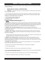
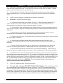
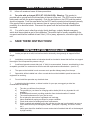
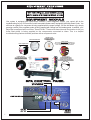
Spa Owner's
Manual
FOR
SPOR UB
NOTE: Important Safety Instructions. Please read and follow all instructions
before installing, operating or enjoying your spa.
Please refer to the operational video that is supplied with spa.
Save these instructions for future reference.
UL
®
UNDERWRITER'S
LABORATORIES
REV08/06
HOTTUBS.COM
A Brief History of Spas
During the 5th century B.C., the mineral springs in Greece and the Aegean Islands served as
healing clinics. At one particular clinic on the Island of Cos, a Greek physician Hypocrites
practiced medicine while writing extensively on hydrotherapy.
In the province of Leige, Belgium mineral springs were favored for centuries by notables and
royalty, including Russian Czar Peter the Great and German Kaiser William II. Mineral springs
in those days were very similar to today's spas in that both were used for therapeutic and
recreation purposes.
The ancient Romans, after a day of conquering the world, retreated to the pleasures of their
mineral springs. In fact, many well-preserved mineral springs built by the ancient Romans still
exist today in places as far off as Bath, England and Tiberias, Israel. After the fall of the
Roman Empire in the 5th century A.D., the number of mineral springs decreased. It was not
until the renaissance, mysteriously enough that they again became popular. This raises an
interesting question: Does the use of mineral springs or spas result in great thinking, or do
great thinkers resort to the use of mineral springs or spas?
Your new SPORTUB™ is the modern machine for today's great thinkers and athletes of any
age. The spa blends many advanced features to help you enjoy the complete benefits of
heated, moving and filtered water for therapy and relaxation. Baja Products, Ltd. is the
originator of the acrylic spa, and has built world class products since 1969. We wish you
years of enjoyment and relaxation with your new Baja spa. Please take a few minutes to read
the valuable safety instructions and operating features described in this manual.
DIRECTORY
SAFETY INSTRUCTIONS.........................................................................................................................................PAGES 2-4
INSTALLATION GUIDELINES.....................................................................................................................................PAGE 4
120 Volt OZONE GENERATOR...................................................................................................................................PAGE 5
ELECTRICAL 120 Volt................................................................................................................................................PAGE 5
GROUND FAULT INTERRUPTER .............................................................................................................................PAGE 5
ELECTRICAL 240 Volt................................................................................................................................................PAGE 6
ST 1057-58 WIRING DIAGRAM …............................................................................................................................PAGE 6
EQUIPMENT FEATURES.............................................................................................................................................PAGE 7
INITIAL START UP........................................................................................................................................................PAGE 8
ST 1050-54-56-57-58-59 CONTROLLER OPERATIONS....................................................................................PAGE 9
QUICK PROGRAMMING NOTES..............................................................................................................................PAGE 10
BAJA EXTREME SOUND PRECAUTIONS...............................................................................................................PAGE 10
INSTALLING YOUR PURIFICATION DISPENSER.................................................................................................PAGE 11
JET & FILTER OPERATION.......................................................................................................................................PAGE 11
CLEANING YOUR FILTER..........................................................................................................................................PAGE 11
CABINET INSTALLATION..........................................................................................................................................PAGE 12
CABINET DRAIN INSTALLATION.............................................................................................................................PAGE 12
SPA MAINTENANCE SCHEDULE............................................................................................................................PAGE 13
REGULAR SPA MAINTENANCE...............................................................................................................................PAGE 13
WINTERIZING/SUMMERIZING YOUR SPA.............................................................................................................PAGE 14
VISUAL DIAGNOSTIC SYSTEM TROUBLESHOOTING........................................................................................PAGE 14
GENERAL TROUBLESHOOTING..............................................................................................................................PAGE 15
CONTROLLER ERROR INDICATORS......................................................................................................................PAGE 16
Date _____Model #____________________________
Serial Number
1
SAFETY INSTRUCTIONS
When installing and using this electrical equipment, basic safety precautions should always be followed,
including the following:
1.
READ AND FOLLOW ALL INSTRUCTIONS.
2.
WARNING - To reduce the risk of injury, do not permit children to use this product unless they are
closely supervised at all times.
3. A wire connector is provided on this unit to connect a minimum No. 8 AWG (8.4 mm2) solid copper
conductor between this unit and any metal equipment, metal enclosures of electrical equipment, metal
water pipe, or conduit within 5 feet (1.5 m) of the unit.
4. For Cord-Connected/Convertible Units
a) Replace damaged cord immediately.
b) Do not bury cord.
c) Connect to a grounded, grounding type receptacle only.
d) NEVER use an Extension Cord of any type.
5. If the supplied cord and plug are not used, the electrical supply for this product must include a suitably
rated switch or circuit breaker to open all ungrounded supply conductors to comply with section 422-20 of
the National Electrical Code, ANSI/NFPA 70. The disconnecting means must be readily accessible to the
spa occupant but installed at least 5 ft. (1.5 m) from spa water. (See GFCI Warning pg. 4)
6. DANGER - Risk of Accidental Drowning. Extreme caution must be exercised to prevent
unauthorized access by children. To avoid accidents, ensure that children do not use this spa unless they
are supervised at all times.
7. DANGER - Risk of Injury. The suction fittings in this spa are sized to match the specific water flow
created by the pump. Should the need arise to replace the suction fittings or the pump, be sure that the
flow rates are compatible.
Never operate spa if the suction fittings are broken or missing. Never replace a suction fitting with one
rated less than the flow rate marked on the original suction fitting.
8. DANGER - Risk of Electric Shock. Install at least 5 feet (1.5 m) from all metal surfaces. As an
alternative, a spa may be installed within 5 feet of metal surfaces if each metal surface is permanently
2
connected by a minimum No. 8 AWG (8.4 mm ) solid copper conductor to the bonding lugs on the control
box that is provided for this purpose.
9. DANGER - Risk of Electric Shock. Do not permit any electric appliance, such as a light, telephone,
radio, or television, within 5 feet (1.5 m) of a spa.
10. Always enter and exit the spa slowly and cautiously. Wet surfaces can be slippery.
11. Do not use the spa alone.
12. People with infections, skin sores or open wounds should not use the spa.
13. It is recommended that people shower before and after using the spa in order to keep spa operating
cleaner, and to rinse off spa water chemicals.
14. Disconnect all electrical power before attempting any kind of service to the electrical module.
15. Always use unbreakable containers around the spa. Never use glass.
2
SAFETY INSTRUCTIONS
16.
Never walk, climb, play or jump on the insulated cover of your spa. Never use the spa unless the
cover has been completely removed. Do not rely on the cover as a safety cover For children. Children
must be supervised when they are in or around the spa.
17.
A fence around your spa with a self-closing and self-latching gate can be the best protection
against unauthorized use. If your spa is indoors, lock the door to the room to keep out unauthorized
users.
18.
Install to provide drainage of compartment with electrical components.
19.
WARNING - To reduce the risk of injury:
a) The water in a spa should never exceed 40°C(104°F). Water temperature between 38°C
(100°F) and 40°C(104°F) are considered safe for a healthy adult. Lower water temperatures are
recommended for young children and when spa use exceeds 10 minutes.
b) Since excessive water temperatures have a high potential for causing fetal damage during the
early months of pregnancy, pregnant or possibly pregnant women should limit spa water temperatures to
38°C(100°F).
c) Before entering a spa, the user should measure the water temperature with an accurate
thermometer since the tolerance of water temperature-regulating devices varies.
d) The use of alcohol, drugs, or medication before or during spa use may lead to unconsciousness
with the possibility of drowning.
e) Persons using medication should consult a physician before using a spa since some
medication may induce drowsiness while other medication may affect heart rate, blood pressure, and
circulation.
f) Persons suffering from obesity or with a medical history of heart disease, low or high blood
pressure, circulatory system problems, or diabetes should consult a physician before using a spa.
g) Should nausea, dizziness or headaches occur, leave the spa immediately. Cool the body by
taking a cool shower or apply cold towels or ice packs. Seek medical attention if the symptoms persists.
20.
Hyperthermia occurs when the internal temperature of the body reaches a level several degrees
above the normal body temperature of 98.6 °F. The symptoms of hyperthermia include an increase in the
internal temperature of the body, dizziness, lethargy, drowsiness and fainting. The effects of hyperthermia
include (1) failure to perceive heat, (2) failure to recognize the need to exit spa, (3) physical inability to exit
spa, (4) fetal damage in pregnant women, (5) unawareness of impending hazard, (6) unconsciousness
resulting in the danger of drowning. WARNING: The use of alcohol, drugs, or medication can
greatly increase the risk of fatal hyperthermia.
21.
Inform all occasional users of these precautions.
22.
For units with an Integral GFCI (ST 1050-54-56-59): Warning - This product is provided
with a ground fault circuit-interrupter at the end of the cord. The GFCI must be tested before
each use with the product operating. Push the test button on the GFCI and the product should
not operate. Push the reset button on the GFCI and the product should operate normally. If the
product fails to operate in this manner, there is a ground current flowing indicating the possibility
of an electrical shock. Disconnect the power until the fault has been identified and corrected.
3
SAFETY INSTRUCTIONS
21.
Inform all occasional users of these precautions.
22.
For units with an Integral GFCI (ST 1050-54-56-59): Warning - This product is
provided with a ground fault circuit-interrupter at the end of the cord. The GFCI must be tested
before each use with the product operating. Push the test button on the GFCI and the product
should not operate. Push the reset button on the GFCI and the product should operate normally.
If the product fails to operate in this manner, there is a ground current flowing indicating the
possibility of an electrical shock. Disconnect the power until the fault has been identified and
corrected.
For units for use in other than single- family dwellings, a clearly labeled emergency
23.
switch shall be provided as part of the installation. The switch shall be readily accessible to the
occupants and shall be installed at least 5 feet (1.52 m) away, adjacent to, and within sight of the
unit.
24.
SAVE THESE INSTRUCTIONS!
INSTALLATION GUIDELINES
1.
Locate your spa on a solid, level surface that is structurally strong enough to support its filled
weight.
2.
Installations on wooden decks or balconies should be checked to insure that the floor can support
the weight of the full spa and the persons using it.
3.
A reinforced poured concrete slab (min. 4" thick) is recommended. However, wood decking is also
acceptable, provided it is constructed so that it meets the requirements outlined above. (see No. 2)
4.
The spa must be installed in such a manner as to provide drainage away from the spa.
5.
Spas which will be installed into a floor or wood deck must be installed to permit access to the
equipment for servicing.
6.
Do not install the spa under any electrical wires.
7.
In selecting the ideal outdoor, or indoor location for your spa, we suggest you take into
consideration the following:
a)
b)
c)
d)
e)
f)
g)
h)
i)
The view you will have from the spa.
The proximity to your home for changing and/or shelter (this is very important in cold
weather).
A sheltered environment, providing protection from wind and weather if needed.
The overall enhancement of your yard or room.
Do not place the spa under a unguttered roof overhang.
Indoor installations require provisions for proper ventilation.
Check local codes for building and fence requirements.
Water is carried and splashed out by the user, be sure the spa is not located in an area or
on a surface that may be damaged by water. (Examples: Carpeting, 2nd floor in house,
etc.)
Indoor spas should be installed in rooms constructed of materials that will not be damaged
by high humidity.
4
120 VOLT OZONE GENERATOR
120 VOLT OZONE GENERATOR INSTALLATION (optional)
The Sportub series are equipped with an ozone feed line ready for the addition of optional
ozone generator.
Located under the spa lip and above the equipment pack please find the coiled ozone feed
line with built in check valve. Connect this line to the barb fitting provided on the ozone
generator leaving the excess tubing coiled under lip. This line is connected to a dedicated
ozone injection spa jet.
The yellow 4-prong plug located on the equipment pack supplies power to the ozonator. Make
sure the electrical pin configuration is matching and then plug in the ozonator. This
receptacle is ON (hot) at all times. Ozone will be injected into spa automatically whenever
the pump is operating on low speed mode (Filtration) or High Speed.
WE RECOMMEND THAT YOU FOLLOW ALL INSTRUCTIONS PROVIDED BY THE
OZONE GENERATOR MANUFACTURER.
120 VOLT INSTALLATION
The provided power supply cord must be connected to a receptacle with a minimum circuit breaker size of 15
amperes. No other electrical appliance or fixture should be used on this circuit.
The heater will provide 1100 watts (1.1 kw) of heat when the pump is operating in low speed and thermostat is calling
for heat.
Under no circumstances should an extension cord be used. Use of an extension cord will seriously degrade
the performance of the equipment module and can create an electrical hazard.
GROUND FAULT INTERRUPTER
Ground-Fault Circuit-Interrupters and Load Neutral Connection
LINE LUG #1
LINE LUG #2
TEST
GFCI
INCOMING
SERVICE
CONDUCTORS
FROM
MAIN
PANEL
(Ground Fault Circuit Interrupter)
CIRCUIT BREAKER
NEUTRAL
GROUND
LOAD
GROUND BUS BAR
LINE 1
LINE 2
NEUTRAL
GROUND
TO SPA CONTROL BOX
5
NEUTRAL BUS BAR
Many GFCI’s are also provided with a “LOAD”
neutral connection terminal. The purpose of the
“LOAD” neutral connection terminal is to allow
the connection of 120 volt devices to the 240 volt
GFCI. If the circuit being connected does not
contain any 120 volt devices, the LOAD neutral
connection is not used, and the GFCI will
provide protection of all 240 volt devices
connected.
A ”LOAD” neutral terminal
connection is NOT needed in order for the GFCI
to function.
LINE 1
LINE 2
NEUTRAL PIGTAIL
Most 240 volt panel mounted Ground-Fault
Circuit-Interrupter’s (GFCI’s) are provided with
a “LINE” neutral connection lead. Since the
GFCI itself is a 120 volt device, this wire must be
connected to the neutral buss bar in order for the
GFCI to function properly.
LOAD NEUTRAL MUST BE
CONNECTED DIRECTLY
TO GFCI AS SHOWN
The heater will provide 4500 watts (4.5kw) of
heat when the pump is on and the thermostat
is calling for heat.
The following instructions must be followed for
a permanently connected Equipment Module
designed to operate at 240 Volts.
GROUND
FIELD
SUPPLIED
WIRING
}
LINE 1
LINE 2
NEUTRAL
FACTORY LINE 1 - BLACK
SUPPLIED LINE 2 - BLUE
WIRING NEUTRAL - WHITE
}
MINIMUM WIRE SIZE FOR LINE 1, LINE 2,
NEUTRAL = #8 AWG.
MINIMUM WIRE SIZE FOR GROUND = #10 AWG
*Refer to local codes for exact wiring size required
and / or N.E.C.
See Below For The ST1057-58 Wiring Diagram
J1= Conversion Jumper
Blue
Across Pins 1 and 2 for
240 Volt Operation
Use copper conductors ONLY!
Blue
Across Pins 2 and 3 for
120 Volt Operation
NOTE: 240 Volt mode allows
pump high speed and heater to
operate at the same time.
SPORTUB 1057-58 WIRING DIAGRAM
240 VOLT - 50 AMP
IMPORTANT: Always refer to the product data label
(Located on top of Control Box) for specific electrical information.
Line 1, Line 2, Neutral and Ground. 8AWG. Minimum
240-Volt electrical service required:
L1 N GR L2
5
6
ST 1050-54-56-59
Your system is equipped with Hydro-Quip’s exclusive, Visual Diagnostic System, your control will do the
troubleshooting for you. VDS consist of control-mounted indicators and (if equipped) HydroQuip Smart Cords. You
will know at a glance if a component is being supplied with the proper voltage, if a fuse has blown or (by simply
pressing a switch) if the complete system is being supplied with voltage from the breaker panel. In addition, your
Baja Spa is equipped with exclusive “Smart Cords”. These cords have internal illumination to let you
know that power is being supplied to the components connected to them. This is a helpful
troubleshooting feature should a problem with a component arise.
VISUAL DIAGNOSTICS
LIGHT CONNECTION
POWER SWITCH
The main ON/OFF switch
for the equipment module
7
HEATER ACTIVE
Illuminates when the
heater is on
SMART CORDS
These cords have internal illumination to
let you know that power is being supplied
to the components connected to them.
GROUND FAULT
CIRCUIT INTERRUPTER
A required safety feature
in cordand plug connected units
INITIAL STARTUP
WARNING
IN ORDER TO CHECK FOR POSSIBLE LEAKS, THE FOLLOWING STEPS ARE PERFORMED
WITHOUT THE EON CABINET IN PLACE. TO PREVENT RISK OF ELECTRICAL SHOCK, DO NOT
USE SPA AT THIS TIME.
1. 120 Volt Units: Make sure the power supply cord is "unplugged". 240 Volt Units: Make sure the power
supply is "OFF".
2. Check to see that the Drain Valve (located to the left side of Equipment Module) is closed.
3. The slide valves on each side of the Equipment Module should be open.
(The valve is open when the handle is pulled out, closed when it is pushed in).
NOTE: Valves snap lock into place in both "open" and "closed" positions.
4. Fill the spa water to 1" above the center line of the skimmer located inside spa. Bleed air
from the filter and equipment module by opening the air relief plug (located on the top of
the filter). Tighten plug when finished. (See pg. 11 Cleaning the Filter)
IMPORTANT NOTE: The Equipment Module must never be operated without water in the spa,
or serious damage to the heater and/or pump could result.
5. Check all plumbing connections for water leaks.
6. Familiarize yourself with controller operations (Pages 9).
7. Apply power to the Equipment Module:
120 Volt Units: Plug cord into dedicated 15 amp outlet.
240 Volt Units: Turn the main disconnect switch to the "ON" position.
8. Push the JET button located on the topside SPORTUB™ control panel. The pump will now operate
at high speed.
9. Set desired temperature.
IMPORTANT NOTE: It is very important the pump be operated on high speed for several
minutes to assure that all air has been removed from system. The thermostat may only be
"turned up" after full water flow has been established.
10. Check for any leaks.
11. Open valves for operation. Close valves for maintenance.
FOR YOUR INFO
If your new spa pump does not prime (flow) on the initial start-up...
You may be experiencing “air lock”
This normal occurrence can be easily corrected by loosening the plumbing union on the left
side of the pump’s suction (your left as you face the equipment) until the water flows into the
pump. Then quickly re-tighten fitting taking care that the O-ring stays in place. Turn on the
LOW SPEED pump setting and you should now have normal flow through the jets.
Note: OPEN AIR RELIEF VALVE on the top of the filter when filling spa.
8
SPORTUB Controller Operations
JETS KEY: The Jets key is used to turn the
pump on or off at selected speeds. The first
press will turn on the pump LOW speed, the
second press will change the pump to HIGH speed,
the third press will turn the pump off or return to a
heat or filtration mode (see note). A built-in timer will shut the
pump off 20 minutes after it has been started unless the user
does so manually. When the pump is on, the Jets On Indicator
will appear above the Jets key. NOTE: You may not be able to
turn the pump off if it has started a filtration cycle or if the spa is
calling for additional heating. This is easily identified by
observing the status of the "Heater On Indicator" or the "Filter
Cycle Indicator". (Models ST 1050,54,56,59)
TEMPERATURE PROGRAM KEYS: The
Up/Down Temperature Program keys are
used to set the desired water temperature.
Press the Up or Down keys to Increase (or
decrease) the desired temperature setting. The temperature can
be adjusted in 1ºF increments from 59ºF to 104ºF (or 15ºC to 40º
C). The desired temperature setting will remain in the display for 5
seconds as confirmation of the new value, after 5 seconds the
display will return to display the present water temperature.
NOTE: The Temperature Program Indicator will appear to indicate
that the temperature in the display is the desired-programmed
temperature and not the actual water temperature.
LIGHT KEY: The Light key is used to turn the light
on or off. The first press of the Light key will turn the
light on. A second press will turn the light off. The
light will automatically turn itself off after 2 hours.
When the light is on, the Light On Indicator will
appear above the Light key.
HEATER OPERATION: When the water temperature drops 1ºF
lower than the desired temperature, the heater will be turned on
until the water temperature reaches the desired temperature plus
1ºF. The Heater On Indicator will appear on the function panel
when it is on. The Heater On Light Indicator will blink on the
function panel whenever there is a call for heat and the heater has
not yet been activated.
Important Note ST Models 1057-58:
Do not program filter cycles or duration on ST Models
1057-58. These spas are designed with a circulation
pump to operate filtration mode 24 per day. Leave in
the factory set filtration mode of 1 cycle for 60 minutes
daily. This Filtration time operates the low speed Jet
Pump for purge only cycle.
Programming Filter Cycles: You may choose to filter the
spa 1, 2 or 3 times per day as required to keep the water clean
and sanitary. Press the Jets Key for 5 seconds. The current
setting will be displayed. Use the Up & Down Arrow keys to
increase or decrease the frequency of the filtration cycles per
day. The filter cycle is now set. To start a filter cycle
immediately, press the Jets key. The cycles will repeat every
8, 12 or 24 hours within a 24-hour period starting from the
time programmed. It is recommended to schedule the
filtration cycles so they do not interfere with sleeping hours.
Programming Filter Cycle Duration: You may choose to
filter your spa 60, 120 or 180, 480 minutes per cycle as
required to keep the water clean and sanitary. Press the Light
Key for 5 seconds. The current duration of the filter cycle will
be displayed. Use the Up & Down Arrow keys to increase or
decrease the duration of the filter cycle. The duration is now
set. To start a filter cycle immediately, press the Light key.
Setting Fahrenheit and Celsius Degrees: Press and hold
the light key for 5-seconds, the display will change to either
setting. When the desired display is shown the display has
been set and nothing else must be done.
* If the spa is being used during the filter cycle, the
cycle will be suspended for a period of 40-minutes or
until the spa is no longer in use.
(Models ST 1050,54,56,59)
FREEZE PROTECTION: When the system senses cold
temperatures, it will automatically engage the freeze protection
mode for a monitoring period of 24 hours. During this time, the
pump will operate for 1 minute every 2 hours to circulate warm
water through the plumbing. When the pump is running due to
this feature, the Filter Cycle Indicator on the spaside panel will
blink. Filter Cycles will operate as determined by the programing
and will not be affected by the Freeze Protection Mode.
HIGH TEMPERATURE PROTECTION: If the water temperature
exceeds 112ºF at the High Temperature probe, the system will
display the message HL and will turn the heater off. After the
water temperature has cooled down, pressing any key on the
spaside panel control will allow the system to restart. If the spa
water temperature does not seem to be elevated, the HL reading
may have been caused by poor water flow or electrical line
interference (e.g. thunderstorms, voltage surges, etc.). Simply
reset and monitor the system. See Troubleshooting, page 15.
NOTE: The Freeze Protection Circuit is in effect at all times that
there is power applied to the system and will automatically engage
if needed.
DEFAULT SYSTEM OPERATIONS: When power is applied, or
there is a temporary loss of power, the system will initiate it's
default programming. The filter cycle starts 24 hours after the
system has been powered up, filters for one hour, and then
repeats every 24 hours. The maintained temperature will default to
100º F. The freeze protection feature will stay in effect. If a power
loss condition is experienced, the spaside display will blink until
any key is pressed. This feature is to let the user know that a
power failure has occurred and that the Temperature Program
point has returned to the default value.
IMPORTANT PROGRAMMING NOTES: (1) If a program change is not made within 5 seconds, the system will default back to
the monitoring mode. (2) While programming, the Pump and Light features may have been activated. Either can be turned off in
the normal way after programming is complete. The display will return to indicate water temperature 5 seconds after the keys
are released.Note: A power outage to the system will erase any programmed settings. If a power outage should occur, it will
then be necessary to re-program the system. Filtering default is 120 minutes, twice a day. Temperature default is 100°
degrees.
9
QUICK PROGRAMMING NOTES
IF YOU APPLY POWER TO SYSTEM AND DO NOTHING ELSE:
1. The primary filter cycle will occur in 24 hours and run for 120 min.
This will repeat every 12 hours.
2. The spa will heat up to and maintain 100º F.
(The freeze protection mode is available if required.)
TO SET OR CHANGE THE FILTER CYCLE START TIMES:
Refer to PROGRAMMING FILTER CYCLES in operating manual.
IF THE FILTER CYCLES ARE NOT RUNNING AT THE BEST TIMES FOR YOUR SLEEPING SCHEDULE,
YOU MUST PROGRAM THE SYSTEM AT A PARTICULAR TIME OF DAY TO ADJUST THE INTERNAL
SYSTEM TIME PATTERN.
Desired Filter Cycles
Programming Time
Filtering Time
1 Cycle per 24 Hour Period
2 Cycles per 24 Hour Period
3 Cycles per 24 hour Period
8:00 PM
8:00 PM
2:00 PM
8:00 PM
8:00 PM & 8:00 AM
10:00 PM, 6:00 AM
& 2:00 PM
Note: The easiest way to change the internal system time pattern is to simply TURN OFF ALL POWER to the
spa for (10) ten seconds and then promptly start your programming procedure.
BAJA EXTREME SOUND PRECAUTIONS
These instructions are for spas equipped with the optional Baja Extreme Sound System
feature (Optional on the ST1057). “Caution-Risk of electrical shock. Do not leave
compartment door open”. Replace components only with identical components.
1. Baja Extreme Sound System controls should not be operated while inside the spa.
2. “WARNING- Prevent Electrocution. Do not connect any auxiliary components (for example
speakers, headphones, additional audio/video components etc.)to the system.
3. These units are not provided with an outdoor antennae. If provided, it should be installed in
accordance with Article 810 of the National Electrical Code.
4. Do not service this product yourself, as opening or removing covers may expose you to
dangerous voltage or other hazards. Refer all servicing to qualified service personnel.
5. If the power supply connections or power supply cord(s) are damaged, water is entering the
audio/video compartment, or any electrical equipment compartment area, the protective shields or
barriers are showing signs of deterioration, or there are signs of other potentially hazardous damage
to the unit, turn off the unit and contact a qualified service technician.
6. The unit should be subjected to periodic routine maintenance once every quarter to make sure
the unit is operating properly.
10
INSTALLING YOUR PURIFICATION DISPENSER
There are several ways that the water chemistry can been maintained in your Baja Spas. As the photos
indicate below, Baja’s built in KLEEN H20 dispenser incorporates the filter lid for either chlorine /
bromine tablets or Nature 2 purification system. The Nature 2 purification system, is only recommended
for personal use or family spa installation. Chlorine/Bromine or similar is recommended for regular and
heavy bather installation. It is very important to maintain proper PH levels between
7.2 - 7.6.
CAUTION:
ALWAYS CONSULT YOUR DEALER FOR
RECOMMENDATION AND MAINTENANCE
DETAILS.
CONSULT YOUR NATURE2 OWNER'S MANUAL
BEFORE INSTALLING PURIFICATION SYSTEM.
Nature 2: Insert Cartridge Replace every 4 months
JET & FILTER OPERATION
JET OPERATION:
OFF
ON
OFF
ON
Open air control fittings when in
HIGH speed Jets mode.
Turn outer ring to direct flow from
TurboStream® to Magna Jets. Each
TurboStream® jet controls bucket
seat jets.
To install (optional) Euro'ssage™,
turn Magna Jet counterclockwise
and pull straight out then turn
Euro’ssage™ slightly
clockwise until you feel it click into
place.
FILTER REMOVAL & CLEANING:
Your Baja Spa comes complete with a 50 Sq. Ft. filter cartridge that is designed to work under pressure. With
normal use, this filter should be removed a minimum of once every 30 days, or anytime you notice an
appreciable decrease of the flow from the spa jets. You should take time to clean the filter.
TO CLEAN THE FILTER:
1.
2.
3.
4.
5.
6.
7.
8.
9.
11
TURN OFF THE POWER.
REMOVE THE COVER FROM THE FILTER UNIT.
OPEN AIR RELIEF PLUG.
PULL TAB AND TURN LOCK RING COUNTERCLOCKWISE (LEFT).
REMOVE CARTRIDGE FROM THE FILTER HOUSING AND CLEAN THOROUGHLY WITH THE PRESSURE
SPRAY NOZZLE FROM A GARDEN HOSE.
REPLACE THE CLEANED FILTER AND TIGHTEN THE LOCKING RING.
TURN ON POWER.
WHEN THE WATER COMES OUT OF THE AIR RELIEF PLUG, CLOSE IT.
WHEN WATER IS FLOWING FULL, SET THERMOSTAT TO DESIRED WATER TEMPERATURE.
SPA CABINET INSTRUCTIONS
1
2
Position corner posts with
corner panel under each
Corner.
Install corner posts to side
panels using panel bolts
and bolt driver. Attach side
panels to corners using
bolts & bolt driver.
3
Completed Baja spa.
NOTE: (1050) Install corner
posts to end panels (2). Attach
side panels (2) to complete.
CABINET DRAIN INSTALLATION
INSTALLATION INSTRUCTIONS FOR CABINET DRAIN VALVE BAJA SPA'S EQUIPPED WITH THE
THRU CABINET DRAIN VALVE WILL INCLUDE:
! Cabinet panel with removable 1 ½” black plug .
! Place this panel in the LEFT CORNER position on models # 1054/57/58/59 and in LEFT SIDE panel
position on Models # 1050/56.
! Black drain valve located to the left of the equipment pack, attached to clear hose with a ¾ hose
clamp.
PLEASE FOLLOW THESE INSTALLATION INSTRUCTIONS, PRIOR TO SKIRT ASSEMBLY AND
FILLING THE SPA WITH WATER:
! Remove / slide clamp with pliers and take out drain valve from clear hose.
! Discard black cabinet plug and install drain thru hole and secure back nut.
! Place panel in place, making sure there are no crimps in line.
! Secure valve to cabinet.
! Re-attach clear hose completely over barbs and re-secure with clamp.
! Complete cabinet installation.
TO DRAIN SPA- MAKE SURE EQUIPMENT IS IN OFF POSITION
! Simply remove the drain cap.
! Attach a garden hose to threads.
! Turn front face counter-clockwise and pull outwards.
There should be a slow but steady flow of water which originates from the gravity
drain located in bottom of the Baja spa.
_
Secure Nut
to Cabinet
3/4” Clear Hose to Spa Gravity Drain
_
_
Clamp to
Hose/Barb
Pull Out & Turn
Counter Clockwise
12
SPA MAINTENANCE SCHEDULE
DAILY
- CHECK WATER LEVEL, REFILL IF NECESSARY TO LINE ON SKIMMER
PLATE.
- CHECK CHEMICAL READING AND ADJUST AS NEEDED.
- FOR PROPER FILTRATION, THE WATER SHOULD BE CIRCULATING
FOR AT LEAST FOUR HOURS A DAY.
WEEKLY
- WIPE DOWN THE WATER LINE.
- CHECK WATER FLOW AND CLEAN FILTER IF NECESSARY.
MONTHLY
- CLEAN FILTER CARTRIDGE.
- CLEAN THE INSULATED SPA COVER.
- TEST THE GFCI.
THREE MONTHS - DRAIN THE SPA COMPLETELY, REFILL WITH WATER AND
REPLENISH CHEMICALS.
- WHILE THE SPA IS EMPTY, CLEAN WITH A NONABRASIVE
ACRYLIC CLEANER AND RINSE.
NOTE: NEVER WAX THE SURFACE AS THE WATER WILL
DISSOLVE THE WAX AND CLOG THE FILTER.
SIX MONTHS:
- CLEAN EON SYNTHETIC CABINET WITH WET TOWEL.
REGULAR SPA MAINTENANCE
DRAINING THE SPA (SEE PAGE 12):
It is recommended to completely drain the spa at least four times a year. More frequent draining
may be required depending on usage. The spa should also be drained if it is not going to be used
for a long period.
An empty spa MUST be covered. Direct sunlight on the acrylic surface can cause severe damage
or blemishing of the acrylic spa surface, and can result in the voiding of the spa surface warranty.
TO DRAIN THE SPA (SEE PAGE 12), COMPLETE THE FOLLOWING STEPS:
1. Turn off the main circuit breaker or disconnect panel.
2. Attach a garden hose to the drain hose bib, and then open hose bib allowing the water to drain
from the spa by gravity. For complete draining, place outlet end of hose below bottom of spa.
CLEANING:
When the acrylic surface becomes soiled, it can be cleaned with a soft cloth or
sponge. DO NOT USE ANY ABRASIVE CLEANERS, as they can scratch or dull
the brilliant acrylic surface.
Your insulated cover can be cleaned with a non-abrasive household cleaner. A non-silicone based
vinyl restorer will help protect the surface from sun damage.
13
WINTERIZING/ SUMMERIZING YOUR SPA
If the spa is to be left unused for an extended period of time in areas where freezing
temperatures DO NOT OCCUR, it may be desirable to turn the heater OFF. To keep
the spa water clean and sparkling, set the timer to filter the water several times each
day. When preparing the spa for use, check the water chemistry to assure correct
chlorine and pH levels.
If it is desired to keep water in the spa during the time of year when freezing may occur,
the heater will operate as required to prevent the water from freezing.
However, CAUTION MUST BE USED WITH THIS APPROACH. In the event of
electrical power interruptions, regardless of cause, the heater and pump will stop
operating and freeze protection will be lost. This could result in freeze damage to the
spa, spa plumbing/and or Equipment Module components. Such damage is not
covered by the Equipment Module Warranty.
If the spa is to be drained for an extended period of time, consult your local retailer for
winterizing your spa completely due to potentially extreme weather conditions.
Smart Winter Mode: In cold climate areas, Baja Spas are equipped with sensors to detect cold
climate situations. These safety sensors will not operate in a power outage. If long outages
are expected, it is best to drain and winterize the spa.
VISUAL DIAGNOSTIC SYSTEM
If your system is equipped with the Visual Diagnostic System, the control will do the troubleshooting
for you! VDS consists of control mounted indicators and (if equipped) exclusive “Smart Cords”. You
will know at a glance if components are being supplied with proper voltage or if an internal fuse has
blown.
VDSfVisual Diagnostic Systemf
System Fuse
If a VDS light is
illuminated, refer to
Owners Manual for
details
Pump 1 Fuse
Auxiliary Fuse (Opt.)
VDS INDICATOR ILLUMINATED
SYSTEM FUSE - This fuse protects
the printed circuit board.
Input voltage connected incorrectly.
Call your local dealer or qualified technician.
PUMP 1 FUSE - Protects the primary
pump.
Restricted flow of water, faulty pump or severe
weather/electrical storm.
Call your local dealer or qualified technician.
AUX. FUSE - Protects the secondary
pump.
Restricted flow of water, faulty pump or severe
weather/electrical storm.
Call your local dealer or qualified technician.
14
TROUBLESHOOTING
Over-Temperature Protection On
Air lock plumbing system.
“Bleed” the system, see start-up procedure page 8.
Restricted flow
Low Level Programming Incorrect- Contact your Dealer
Thermal Overload Tripping.
Check for restricted flow of water
15
Current Limiting On- 120V Systems will not heat if High-Speed is on.
Contact your dealer
CONTROLLER ERROR INDICATORS
PRESSURE or FLOW SWITCH ACTIVATED - This error will be displayed only when the pump
is not activated. Cycle the pump through Low & High speeds then off. If the error does not clear,
this is an indication that the pressure or flow switch is activated with no water flow.
FLC
104
fLo
P
OH
PRESSURE or FLOW SWITCH NOT ACTIVATED - This error will be displayed while the pump
is running. Cycle the pump through Low & High speeds. If the error does not clear, this is an
indication that the pressure or flow switch has not activated although there is water flow.
TEMPERATURE SENSOR MALFUNCTION - This error will occur when a problem with the
temperature sensor exists. This error may also occur if the system is activated while the water
temperature is below 35°F.
OVERHEAT or HIGH-LIMIT PROTECTION - There are three(3) stages of over-temperture:
1 - The spa water has exceeded 112F. The heater, pump and accessory will be deactivated until
the water cools to 109°F. Be sure to check the actual water temperature with an accurate
thermometer.
2 - The spa water has exceeded 119°F. The heater will deactivate while the pump and accessory
will still operate. WATER MUST BE BELOW 119°F AND POWER MUST BE RESET TO CLEAR
THE “HL” ERROR
A dirty spa filter can also cause a restricted flow of water, be sure the filter is cleaned regularly
and ensure all water shutoff valves are open.
Hl
If the system has been operating normally until now, the pump may be overheating the spa.
Refer to “Programing Filtration” on page 10 and reduce the duration and/or number of cycles per
day.
3 - If you’ve eliminated items 1 & 2 as problems, the high-limit sensor may have malfunctioned.
FREEZE PROTECTION - There are two(2) levels of freeze protection integrated into the
system.
f ee
1 - SMART WINTER MODE, this mode will activate any time the temperature falls below
59°F. This mode will be active for a period of 24-hours. In this mode, if a pump has not
been activated in the last 2 hours, the system will automatically turn it on for 1-minute to
prevent freezing. The “Filter Cycle” indicator will flash while this mode is active.
2 - If the spa water temperature drops below 49°F, the heater & pump will be activated until
the water temperature reaches 50°F. While freeze protection is active, no other
functions will be possible.
16