1
A D I R O N DA C K S PA S ®
OWNER’S MANUAL
the
Adirondack Edition
Model: ________________________________________________________
Serial Number: _________________________________________________
Date Installed: __________________________________________________
Dealer: ________________________________________________________
Address: _______________________________________________________
Telephone: _____________________________________________________
Note: The serial number/identification label is located within the equipment
compartment and skimmer housing.
A D I R ONDAC K S PAS ® S ERIES
MODEL
AV G . F I L L
AV G . F I L L W E I G H T
AV G . D R Y W E I G H T
KEENE
150 gal. / 568 L
1638 lbs. / 743 kg.
385 lbs. / 175 kg.
CHAMPLAIN
240 gal. / 909 L
2504 lbs. / 1136 kg.
500 lbs. / 227 kg.
CAROGA
350 gal./ 1325 L
3500 lbs./ 1587 kg.
700 lbs./ 318 kg.
SARANAC
350 gal. / 1325 L
3622 lbs. / 1643 kg.
700 lbs. / 318 kg.
CASCADE
375 gal./ 1420 L
3911 lbs./ 1774 kg.
780 lbs. / 354 kg.
MARCY
375 gal. / 1420 L
3880 lbs. / 1760 kg.
750 lbs. / 340 kg.
GEORGIAN
525 gal. / 1988 L
5302 lbs. / 2405 kg.
920 lbs. / 417 kg.
REGENT LE
425 gal. / 1609 L
4297 lbs. / 1549 kg.
750 lbs. / 340 kg.
Thank you for your recent Adirondack Spas® purchase.
This owner's manual has been designed to acquaint you with your Saratoga Spa’s operation
and general maintenance. Keep this manual available for future reference.
If you have any questions regarding your Adirondack Spas®, contact your local dealer.
Thank you.
*Use the LE INSTRUCTIONS for the Regent LE
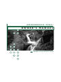
TABL E O F CON TE NTS
CON T R O L PA N E L F U N CT I ON S S E M O DE LS
A D I RONDAC K SPA S ® S A FE TY
I N S TRU C TIONS
Avoiding The Risk to Children . . . . . . . . . . . . . . .
Avoiding Risk of Electrical Shock . . . . . . . . . . . . . .
Avoiding Risk of Injury . . . . . . . . . . . . . . . . . . . . .
Unclean Water . . . . . . . . . . . . . . . . . . . . . . . . . . . .
Avoiding Risk of Hyperthermia . . . . . . . . . . . . . . .
Avoiding Risk of Skin Burns . . . . . . . . . . . . . . . . .
Important Do's and Don'ts . . . . . . . . . . . . . . . . . .
2
2
3
3
4
4
5
ADI R ON DACK SPA S ® M O D E LS
Spa Specifications . . . . . . . . . . . . . . . . . . . . . . . . . 6
ADI R ON DACK SPA S ® F E ATU RE S A ND
OP E R ATI ON S
Keene . . . . . . . . . . . . . . . . . . . . . . . . . . . . . . . . . . . 7
Champlain . . . . . . . . . . . . . . . . . . . . . . . . . . . . . . . 8
Caroga . . . . . . . . . . . . . . . . . . . . . . . . . . . . . . . . . . 9
Saranac . . . . . . . . . . . . . . . . . . . . . . . . . . . . . . . . . 10
Cascade . . . . . . . . . . . . . . . . . . . . . . . . . . . . . . . . 11
Marcy . . . . . . . . . . . . . . . . . . . . . . . . . . . . . . . . . . 12
Georgian . . . . . . . . . . . . . . . . . . . . . . . . . . . . . . . 13
Regent LE . . . . . . . . . . . . . . . . . . . . . . . . . . . . . . 14
INS TALLATI ON INS TRU C TIONS
Location Preparation . . . . . . . . . . . . . . . . . . . . . . 15
Outdoor Installation . . . . . . . . . . . . . . . . . . . . . . 15
Indoor Installation . . . . . . . . . . . . . . . . . . . . . . . 15
ELECTR I CAL R EQU IRE M E NTS
AND PR ECAUTI ONS
220 V Permanently Connected SE & LE Models 16
Electrical Installation Instructions . . . . . . . . . . . . 16
Electrical Spa Wiring Connection Instructions . . 17
110/220 Volt Convertible Models . . . . . . . . . 18-19
INITIAL OPER AT ING INS TRU C TIONS
Start-up and Refill Procedures . . . . . . . . . . . . . . . 20
SE Model Start-up Procedures . . . . . . . . . . . . . . . 21
LE Model Start-up Procedures . . . . . . . . . . . . . . 22
Jet & Valve Specifications . . . . . . . . . . . . . . . . 23-24
EQUI PMEN T MA INTE NA NC E
Light Bulb Replacement . . . . . . . . . . . . . . . . . . . 25
Main Control Panel . . . . . . . . . . . . . . . . . . . . . . . 25
Main Control Panel Navigation . . . . . . . . . . . . . . . 25
Temperature Controls . . . . . . . . . . . . . . . . . . 25-26
Panel Functions . . . . . . . . . . . . . . . . . . . . . . . . . . 26
Hold, Lock/Unlock, 24 Hr Clock,
Temp display, Flip Button
Operating the Hydro Pumps . . . . . . . . . . . . . . . . 27
Jet Buttons . . . . . . . . . . . . . . . . . . . . . . . . . . . . . 27
Clean Up Cycle . . . . . . . . . . . . . . . . . . . . . . . . . . 27
Light Control Button . . . . . . . . . . . . . . . . . . . . . 27
Optional LED Lighting Systems . . . . . . . . . . . . . . 27
SE Heating Modes . . . . . . . . . . . . . . . . . . . . . . . . 28
SE Filter Cycle Modes . . . . . . . . . . . . . . . . . . 29-30
SE Reminder Messages . . . . . . . . . . . . . . . . . . . . . 31
SE Diagnostic Messages . . . . . . . . . . . . . . . . . . . . 35
CON T R O L PA N E L F U N CT I ON S L E M O DE LS
Main Control Panel . . . . . . . . . . . . . . . . . . . . . . .
Main Control Panel Buttons & Digital Display . . . . . .
Temperature Control . . . . . . . . . . . . . . . . . . . . . .
Operating the Hydro Pumps . . . . . . . . . . . . . . . .
Jet Buttons . . . . . . . . . . . . . . . . . . . . . . . . . . . . .
Light Control Button . . . . . . . . . . . . . . . . . . . . .
Optional LED Lighting System . . . . . . . . . . . . . . . . . . .
LE Heating Modes . . . . . . . . . . . . . . . . . . . . . . . .
LE Filter Cycle Modes . . . . . . . . . . . . . . . . . . . . .
Summer Set Mode . . . . . . . . . . . . . . . . . . . . . . . .
Freeze Protection . . . . . . . . . . . . . . . . . . . . . . . . .
Automated Purge Cycle . . . . . . . . . . . . . . . . . . . .
LE Diagnostic Messages . . . . . . . . . . . . . . . . . . . .
32
32
32
33
33
33
33
34
34
34
34
34
36
S PA CA R E & WAT E R M A I N T E NA N C E
General Information . . . . . . . . . . . . . . . . . . . 37-38
Filter Cartridge Removal and Cleaning . . . . . . . . 38
Care of Pillows . . . . . . . . . . . . . . . . . . . . . . . 38-39
Care of Exterior . . . . . . . . . . . . . . . . . . . . . . . . . . 39
Care of Spa Cover . . . . . . . . . . . . . . . . . . . . . 39-40
Winterizing Your Spa . . . . . . . . . . . . . . . . . . 40-41
Water Quality Maintenance . . . . . . . . . . . . . 42-44
T R O U BLE S H O OT I N G
SE Operational Trouble Shooting Guide . . . . . . . 45
LE Operational Trouble Shooting Guide . . . 46-47
Control Panel Identification . . . . . . . . . . . . . . . . . 47
S E RVI C E A N D WA R R A N T Y
IN F O R M AT I ON
Service and Warranty Information . . . . . . . . . . . 48
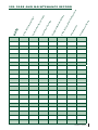
Spa Care and Maintenance Record . . . . . . . . . . . 49
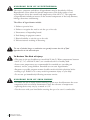
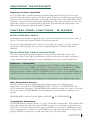
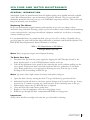
ADIRONDACK SPAS® SAFETY INSTRUCTIONS
Read And Follow All Instructions
AVOIDING THE RISK TO CHILDREN
RISK O F CHIL D D ROWNING
!
Extreme caution must be exercised to prevent unauthorized access by children. To avoid
accidents, ensure that children cannot use a spa unless they are supervised at all times.
!
!
!
• To reduce the risk of injury, do not permit children to use this spa unless they are
closely supervised at all times.
• To reduce the risk of injury, lower water temperatures and control the time of hot
water exposure for young children. Children are especially sensitive to hot water.
R ISK O F EL E C TRO C U TION
• Connect only to a grounded source.
• Do not bury the power cord. A buried power cord may result in death, or serious
personal injury due to electrocution if direct burial-type cable is not used, or if
improper digging occurs.
• A ground terminal (pressure wire connector) is provided on the control box inside the
unit to permit connection of a minimum No. 8 AWG (8.4 mm2) solid copper bonding
conductor between this point and any metal equipment, metal water pipe, metal
enclosures of electrical equipment, or conduit within five feet (1.5 m) of the unit as
needed to comply with local requirements.
• To reduce the risk of electrocution, replace all damaged cords immediately. Failure to
do so may result in death or serious personal injury due to electrocution.
• Do not connect any auxiliary components (for example, additional cable speakers,
headphones or other audio components) to the audio system unless approved by
Saratoga Spa® Company.
• Do not self-service audio components by opening or removing the cover as this
may expose you to dangerous voltage or other risk of injury. Only qualified service
personal should service your spa and it's components.
!
!
2
• Do not attach an external antenna to a spa audio system unless it is installed by a
licensed electrician in accordance with Article 810 of the National Electric Code,
ANSI/NFPA 70.
AVOIDING RISK OF ELECTRICAL SHOCK
• Do not permit any electrical appliance, such as a light, telephone, radio or television
within 5 feet (1.5m) of a spa. These units DO NOT have an internal ground fault
circuit interrupter. The installation of a ground fault circuit interrupter MUST be
done by a qualified Electrician and must meet all local and national codes. Failure
to maintain a safe distance may result in death, or serious personal injury due to
electrocution, if the appliance should fall into the spa.
A di ro nda ck Spa s ®
OWNER 'S M A N UA L
• Install at least 5 feet (1.5 m) from all metal surfaces. A spa may be installed within 5 feet
of a metal surface if each metal surface is permanently connected by a minimum No. 8
AWG (8.4 mm2) solid copper conductor attached to the wire ground connector on the
terminal box that is provided for this purpose if in accordance with National Electrical
Code ANSI/NMFPA70-1993.
!
• Install your spa in such a way that drainage is away from the electrical compartment
and from all electrical components.
!
AVOIDING RISK OF INJURY
• To reduce the risk of injury to persons, DO NOT remove suction fittings located at
the bottom footwell of the spa.
• The suction fittings in the spa are sized to match the specific water flow created by the
pump. Never replace a suction fitting with one rated less than the flow rate marked on
the original suction fitting. Never operate the spa if the suction fittings are broken or
missing.
• There is a danger of slipping and falling. Remember that wet surfaces can be very
slippery. Take care when entering or exiting the spa.
• People with infectious diseases should not use the spa.
• Keep any loose articles of clothing or hanging jewelry away from rotating jets or other
moving components.
• The use of drugs, alcohol, or medication before or during spa use may lead to
unconsciousness with the possibility of drowning.
• Persons using medications should consult a physician before using a spa; some medication
may cause a user to become drowsy, while other medication may affect heart rate, blood
pressure, and circulation.
• Persons taking medications which induce drowsiness, such as tranquilizers,
antihistamines or anticoagulants should not use the spa.
• Water temperature in excess of 104ºF (38ºC) may be injurious to your health.
• Pregnant women should consult a physician before using spa.
• Persons suffering from obesity, or with a medical history of heart disease, low or high
blood pressure, circulatory system problems, or diabetes should consult a physician
before using spa.
• Persons using or having Implanted Pacemakers or Defibrillators should consult their
physician prior to using a spa, as there are risks of electrocution.
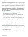
UNCLEAN WATER
• Keep the water clean and sanitized with correct chemical care.
• Maintain water chemistry in accordance with chemical manufacturer’s instructions.
Important:
•Turn the Jet Pump on high speed after adding ANY spa water chemicals into the spa. It will
operate for a 15 minute cycle before shutting off automatically.
• Clean the filter cartridges monthly to remove debris and mineral buildup which may
affect the performance of the jets, limit the flow, or cause a heater-limit issue
Ad iron d ac k S p as ®
OWN E R' S M AN UAL
3
!
!
AVOIDING RISK OF HYPERTHERMIA
The causes, symptoms and effects of hyperthermia may be described as follows:
Hyperthermia occurs when the internal temperature of the body reaches a level
several degrees above the normal body temperature of 98.6ºF/37°C. The symptoms
of hyperthermia include an increase in the internal temperature of the body, dizziness,
lethargy, drowsiness and fainting.
The effects of hyperthermia include:
1. Failure to perceive heat.
2. Failure to recognize the need to exit the spa or hot tub.
3. Unawareness of impending hazard.
4. Fetal damage in pregnant women.
!
5. Physical inability to exit the spa or hot tub.
6. Unconsciousness resulting in drowning.
!!
The use of alcohol, drugs, or medication can greatly increase the risk of fatal
hyperthermia in hot tubs and spas.
!
To Reduce The Risk of Injury:
• The water in the spa should never exceed 104°F (40ºC). Water temperatures between
100°F (37.7ºC) and 104°F (40ºC) are considered safe for a healthy adult.
• Lower water temperatures are recommended for extended use (exceeding ten
minutes) and for young children. Extended use can cause hyperthermia.
!
!
• Pregnant or possibly pregnant women should consult with their physician before
entering a spa. Failure to do so may result in permanent injury to your baby.
• Do not use spa immediately following strenuous exercise.
AVOIDING RISK OF SKIN BUR NS
• To reduce the risk of injury, before entering a spa the user should measure the water
temperature with an accurate thermometer, since the tolerance of temperatureregulating devices may vary by as much as ±5°F.
• Test the water with your hand before entering the spa to be sure it’s comfortable.
4
A di ro nda ck Spa s ®
OWNER 'S M A N UA L
Important:
The following contains important spa information, and we strongly encourage you
to read and apply them.
!
!
!
!
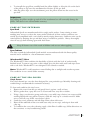
IMPO RTA NT D O'S & D ON'TS
Do:
• Make sure you always lock the child resistant spa cover locks after using the spa for
your children’s safety. Every Adirondack Spas® model is equipped with a locking cover
that meets the ASTM F1346-91 Standard for Safety Covers.
• Test the water temperature with your hand before allowing children to enter the spa to
be sure that it’s comfortable. Children are especially sensitive to hot water.
• Remind children that wet surfaces can be very slippery. Make sure that children are
careful when entering or exiting the spa.
• Use and lock the vinyl cover when the spa is not in use, whether it is empty or full.
• Follow the Spa Care and Maintenance recommendations stated in this manual.
• Use only approved accessories and recommended spa chemicals and cleaners.
• Keep the spa cover locked when the spa is not in use.
• Check the equipment compartment monthly for any signs of tampering to the spa
equipment.
• Follow the maintenance instructions of the spa found in this owner’s manual.
• Be sure your spa is connected to the power supply correctly - use a licensed electrical
contractor.
• Test the Ground Fault Circuit Interrupter(s) once a month.
• Place the spa on a level load bearing surface.
Don't:
• Allow children or pets to climb onto the spa cover.
• Allow children to have unsupervised access to the spa.
• Leave the Adirondack Spas® exposed to the sun without water or the cover in place.
Exposure to direct sunlight can cause solar distress of the shell material and will void
the warranty.
• Lift or drag the vinyl cover by using the cover lock straps; always lift or carry the cover
by using the handles.
• Attempt to open the electrical control box. There are no user serviceable parts inside.
Opening of the control box by the spa owner will void the warranty. If you have an
operational problem, carefully go through the steps outlined in the Troubleshooting
section. If you are not able to resolve the problem, contact your authorized
Adirondack Spas® dealer. Many problems can easily be diagnosed over the telephone
by an Authorized Service Technician.
• Block or sit on the filter compartment area.
• Allow excessive weight to be placed on the spa cover. Doing so could damage the spa
cover and void any warranty.
• Use the spa with the equipment compartment door removed.
• Place electrical appliances within 5 feet (1.5m) of the spa.
• Block the equipment compartment vents. This could cause damage to the spa
equipment and will void the warranty.
* S AV E T H E S E I N S T R U C T I O N S *
Ad iron d ac k S p as ®
OWN E R' S M AN UAL
5
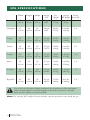
S PA S P E C IF IC ATIONS
Width
Length Height
Average
Fill
Dry Weight
Average
Seating Fill Weight Locations
Keene
57”
1.45 m
80”
2.03 m
29”
0.74 m
150 gal
568 L
385 lbs.
175 kg.
1,638 lbs.
743 kg.
2
Champlain
67”
1.70 m
80”
2.03 m
34”
0.86 m
240 gal
909 L
500 lbs.
227 kg.
2,504 lbs.
1136 kg.
3-4
Caroga
80”
2.03 m
84”
2.13 m
36”
0.91 m
350 gal
1,325 L
700 lbs.
318 kg.
3,500 lbs.
1,588 kg.
4–5
Saranac
80”
2.03 m
84”
2.13 m
36”
0.91 m
350 gal
1,325 L
700 lbs.
318 kg.
3,662 lbs.
1,643 kg.
4-5
Cascade
84”
2.13 m
84”
2.13 m
38”
0.97 m
375 gal
1,420 L
780 lbs.
354 kg.
3,911 lbs.
1774 kg.
5-6
Marcy
84”
2.13 m
84”
2.13 m
38”
0.97 m
375 gal
1,420 L
750 lbs.
340 kg.
3,880 lbs.
1,760 kg.
5-6
Georgian
89”
2.26 m
93”
2.36 m
40”
1.02 m
525 gal
1,988 L
920 lbs.
417 kg.
5,302 lbs.
2,405 kg.
6
Regent LE
84"
2.13 m
90"
2.29 m
38"
0.97 m
425 gal
1609 L
750 lbs.
340 kg.
4297 lbs.
1,949 kg.
5-6
!
!
Due to the risk of property damage and injury, the manufacturer of the Adirondack
Spas® strongly suggests a structural engineer or licensed contractor be consulted
before the spa is placed on an elevated deck.
Note: The “Average Full” weight of the spa includes only the spa and the water inside the spa.
6
A di ro nda ck Spa s ®
OWNER 'S M A N UA L
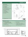
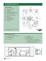
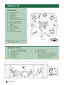
KE E NE S E
REAR
Spa Features
GH
K I
B
D
L
J
RIGHT
E
LEFT
A. Air Control Valve
B. Cluster Jets
C. Standard Jets
D. Deluxe Jets
E. Footwell Spa Drain
F. Backlit Digital Control Panel
G. Microban® Filtration
H. Top-loading Skimmer
I. Pillows
J. Mood Light
K. Power Massage®
L. Versa-Flo™ Valve
M. Waterfall
B
A
D
C
B
D
I
Note: LE Model adds a Vortex Circulation Jet & Deluxe Digital Control
F
F RO N T
M
*F
LE Control Panel
Operations Center
1.
2.
3.
4.
5.
6. Mood Light (located on left side of spa)
7. Shut-off Valves
(1) Two Speed Hydro Pump
1 kW/4 kW Heater (SE only)
110V/220V Power Pack (SE only)
Drain Valve
Bonding Terminal
8. * LE Model adds a Continuous
Circulation Pump and upgraded pack to
the equipment bay. This may create an
optional equipment layout.
*LE Version 220V/4kW Heater only
6
7
1
4
2 7
5
3
*8
LE Circulation Pump
Ad iron d ac k S p as ®
OWN E R' S M AN UAL
7
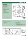
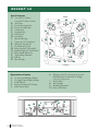
CHAMP LA IN SE
Spa Features
REAR
A. Air Control Valves
B. Cluster Jets
C. Deluxe Jets
D. Footwell Spa Drain
E. Backlit Digital Control Panel
F. Microban® Filtration
G. Top-loading Skimmer
H. Pillows
I. Mood Light
J. Power Massage®
K. Versa-Flo™ Valve
L. Waterfall
L
H
B
H
C
C
Y
CM
LEFT
M
D
F
G
B
MY
C
CY
CMY
B
C
H
J
C
I
A
E
F RO N T
Note: LE Model adds a Vortex Circulation Jet & Deluxe Digital Control
C
D
B
K
RIGHT
C
K
*E
LE Control Panel
Operations Center
1.
2.
3.
4.
5. Mood Light
6. Bonding Terminal
7. Shut-off Valves
(1) Two Speed Hydro Pump
4 kW Heater
220V Power Pack
Drain Valve
*8. Note: LE Model adds a Continuous
Circulation Pump and upgraded pack
to the equipment bay. This may create
an optional equipment layout.
5
7
1
4
8
A di ro nda ck Spa s ®
OWNER 'S M A N UA L
2
3
6
8
7
*8
LE Circulation Pump
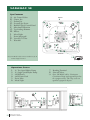
C A R O GA S E
Spa Features
REAR
B
B
G
H
B
A
I
Note: LE Model adds a Vortex Circulation
Jet & Deluxe Digital Control
D
B
B
D
K
L
B
C
D
E
B
D
I
D
RIGHT
M
I
LEFT
A. Air Control Valves
B. Cluster Jets
C. Standard Jets
D. Deluxe Jets
E. Footwell Spa Drain
F. Backlit Digital Control Panel
G. Microban® Filtration
H. Top-loading Skimmer
I. Pillows
J. Mood Light
K. Power Massage®
L. Versa-Flo™ Valve
M. Waterfall
J
D
F
F RO N T
I
*F
LE Control Panel
Operations Center
1.
2.
3.
4.
5. Mood Light
6. Bonding Terminal
7. Shut-off Valves
(1) Two Speed Hydro Pump
4 kW Heater
220V Power Pack
Drain Valve
*8. Note: LE Model adds a Continuous
Circulation Pump and upgraded pack
to the equipment bay. This may create
an optional equipment layout.
5
7
1
4
2
3
6
8
7
*8
LE Circulation Pump
Ad iron d ac k S p as ®
OWN E R' S M AN UAL
9
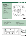
SA R A NAC SE
Spa Features
REAR
L
C
B
C
B
C
F
G
D
A
I
E
C
H
C J
B
C
A
B
C
H
RIGHT
H
LEFT
A. Air Control Valves
B. Cluster Jets
C. Deluxe Jets
D. Footwell Spa Drain
E. Backlit Digital Control Panel
F. Microban® Filtration
G. Top-loading Skimmer
H. Pillows
I. Mood Light
J. Power Massage®
K. Versa-Flo™ Valve
L. Waterfall
K
F RO N T
Note: LE Model adds a Vortex Circulation Jet & Deluxe Digital Control
*E
LE Control Panel
Operations Center
1.
2.
3.
4.
5.
6.
7. Bonding Terminal
8. Shut-off Valves
(1) Two Speed Hydro Pump
(1) Single Speed Hydro Pump
4 kW Heater
220V Power Pack
Drain Valve
Mood Light
*9. Note: LE Model adds a Continuous
Circulation Pump and upgraded pack to
the equipment bay. This may create an
optional equipment layout.
6
8
8
3 8
1
5
10
A di ro nda ck Spa s ®
OWNER 'S M A N UA L
4
7
9
2
8
*9
LE Circulation Pump
CASCADE SE
Spa Features
REAR
M
A
D
D
I
C
K
C
N
D
C
H
G
E
C
O
I
D
J
L
B
F
RIGHT
I
LEFT
A. Air Control Valves
B. Cluster Jets
C. Standard Jets
D. Deluxe Jets
E. Footwell Spa Drain
F. Backlit Digital Control Panel
G. Microban® Filtration
H. Top-loading Skimmer
I. Pillows
J. Mood Light
K. Power Massage®
L. Versa-Flo™ Valve
M. Waterfall
N. Versa-Flo™ Micro Valve
O. Master-Flo™ Massage
I
A
F RO N T
Note: LE Model adds a Vortex Circulation Jet & Deluxe Digital Control
*E
LE Control Panel
Operations Center
1.
2.
3.
4.
5.
6.
7. Bonding Terminal
8. Shut-off Valves
(1) Two Speed Hydro Pump
(1) Single Speed Hydro Pump
4 kW Heater
220V Power Pack
Drain Valve
Mood Light
*9. Note: LE Model adds a Continuous
Circulation Pump and upgraded pack
to the equipment bay. This may create
an optional equipment layout.
6
8
1
5
7
9
3
4
8
8
2
8
*9
LE Circulation Pump
Ad iron d ac k S p as ®
OWN E R' S M AN UAL
11
MA R C Y S E
REAR
A
I
B
D
B
E
G
H
D
C
D
J
I
A
B
N
B
I
M
B
D
LEFT
A. Air Control Valves
B. Cluster Jets
C. Standard Jets
D. Deluxe Jets
E. Footwell Spa Drain
F. Backlit Digital Control Panel
G. Microban® Filtration
H. Top-loading Skimmer
I. Pillows
J. Mood Light
K. Power Massage®
L. Versa-Flo™ Valve
M. Waterfall
N. Master-Flo™ Massage
B
D
D
B
F
F RO N T
Note: LE Model adds a Vortex Circulation Jet & Deluxe Digital Control
RIGHT
Spa Features
B
I
K
B
L
*F
LE Control Panel
Operations Center
1.
2.
3.
4.
5.
6.
1
5
A di ro nda ck Spa s ®
OWNER 'S M A N UA L
*9. Note: LE Model adds a Continuous
Circulation Pump and upgraded pack
to the equipment bay. This may create
an optional equipment layout.
6
8
12
7. Bonding Terminal
8. Shut-off Valves
(1) Two Speed Hydro Pump
(1) Single Speed Hydro Pump
4 kW Heater
220V Power Pack
Drain Valve
Mood Light
7
3
4
9
8
8
2
8
*9
LE Circulation Pump
G E O R G IA N S E
Spa Features
REAR
M
A
I
D
C
B
E
D
B
B
N
D
B
B
D
D
G H
I
B
B
B
LEFT
A
D
J B
F
F RO N T
Note: LE Model adds a Vortex Circulation Jet & Deluxe Digital Control
B
A
RIGHT
A. Air Control Valves
B. Cluster Jets
C. Standard Jets
D. Deluxe Jets
E. Footwell Spa Drain
F. Backlit Digital Control Panel
G. Microban® Filtration
H. Top-loading Skimmer
I. Pillows
J. Mood Light
K. Power Massage®
L. Versa-Flo™ Valve
M. Waterfall
N. Master-Flo™ Massage
I
K
L
*F
LE Control Panel
Operations Center
1.
2.
3.
4.
5.
6.
7. Bonding Terminal
8. Shut-off Valves
(1) Two Speed Hydro Pump
(1) Single Speed Hydro Pump
4 kW Heater
220V Power Pack
Drain Valve
Mood Light
*9. Note: LE Model adds a Continuous
Circulation Pump and upgraded pack
to the equipment bay. This may create
an optional equipment layout.
6
8
1
7
5
4
3
9
8
8
2
8
*9
LE Circulation Pump
Ad iron d ac k S p as ®
OWN E R' S M AN UAL
13
RE GEN T L E
Spa Features
REAR
C
M
Y
M
CQ
A
H
G
E
E
CY
F
D
Q
F
C
G
R
A
J
K L
I
MY
K
Q
E
CM
CMY
G
E
E
Q
B
G
A
LEFT
Versa-Flo™ Micro Valves
B. Air Valves
C. Power Massage® Jets
D. Power Stream® Jets
E. Cluster Jets
F. Standard Jets
G. Deluxe Jets
H. Storm Jets
I. Master Massage
J. Vortex Jet™ Circulation
K. Whisper Clean® Jet
L. Footwell Spa Drain
M. Relax Stream™ Waterfall
N. Backlit Digital Control Panel
O. Microban® Filtration
P. Toploading Skimmer
Q. Pillows
R. Mood Light
B
O
P
N
F RO N T
Operations Center
6. Whisper Zone™ Ozonator- Located
1.
2.
3.
4.
5.
7. Drain Valve
8. Mood Light
9. Bonding Terminal
10.Shut- Off Valves
10
1
14
behind Purity Circulation™ Pump
(1) Two Speed Hydro Pump
(1) Single Speed Hydro Pump
4 kW Heater
Purity Circulation™ Pump
220V Power Pack
A di ro nda ck Spa s ®
OWNER 'S M A N UA L
10
7
10
(Optional on Regent LE)
3
9
4
5
6
8
10
10
10
2
RIGHT
A. Versa-Flo™ Valves/
IN S TA LLAT ION INS TRU C TIONS
Location Preparation
Your Adirondack Spas®model is totally self-contained and portable. You can install the spa
outside or inside. Preferable places are on a patio, deck or indoors. The spa should always be
placed on a level, load bearing surface in accordance with your local building code requirements.
Other items you need to consider are the following:
• Verify that the location chosen can support the weight of the spa, the water of the spa and
its occupants.
• Always check the surface of the site to see if it is level before filling the spa with water.
• Allow access to the equipment compartment for routine maintenance.
• When positioning the spa, be sure to allow for drainage away from the electrical compartment.
• Leave easy access to the GFCI breaker.
!
!
Adirondack Spas® is manufactured to be a portable unit. Any permanent
installation of this product is done at the risk of the owner. Permanent
installation of this unit violates warranty coverage.
Outdoor Installation
Always keep in mind what type of climate you live in. In a climate with cold, snowy winters you
may want to consider locating the spa close to the house for easy access. In climates where it is
normally warm or hot year-round, it would be recommended to place the spa in a shaded or cool
area. With deck installations it is recommended that a qualified building contractor or structural
engineer review the weight the deck can support. The spa specification sheet (on page 6) can
assist you with the weights and dimensions of your spa.
Indoor Installation
Special requirements are needed for indoor installation. Spas normally produce moisture. A
ventilation system needs to be considered. Your spa area should contain moisture resistant wall/
floor coverings and building materials to avoid damage from moisture over time. Proper drainage
of the spa water also needs to be considered.
!
!
Your Adirondack Spas® model is equipped with air vents to allow for circulation of
air throughout the equipment compartment. These vents are found on the face of the
equipment compartment panel and under the corners of the spa at the equipment
compartment end. Do not allow vents to be blocked as to prevent the circulation of air
in the equipment compartment.
Your Adirondack Spas® dealer can help you with information such as
local zoning regulations and building codes.
Ad iron d ac k S p as ®
OWN E R' S M AN UAL
15
EL EC TR I C A L REQ U IREMENTS A ND P RECAUTIONS
Your Adirondack Spas® model has gone through numerous tests to verify that all of the spa
functions operate. Beyond the tests, your Adirondack Spas® model has been designed to
provide the maximum safety against electrical shock. Read and follow the electrical installation
requirements and instructions completely. The next few pages will assist you in properly
connecting the electrical input. Follow the electrical instructions for your specific spa model.
Serious risks or injuries may occur if the spa is improperly wired.
!
!
220 Volt Permanently Connected SE and LE Models:
• Keene* • Champlain • Saranac • Caroga • Cascade • Marcy
• Georgian • Regent LE
*This model is convertible to 110V—See page 18 for installation instructions.
Adirondack Spas® must be wired in accordance with all applicable local electrical
codes. Use NEC 250-122(table) and local codes for more information. All electrical
work should be done by an experienced, licensed Electrician. We recommend the use of
appropriate electrical conduit, fittings and wire for all circuits.
220 Volt installations require a 60Hz, single phase, three-wire electrical service plus
ground (Line 1, Line 2, Neutral and Ground) and must be connected using a minimum
supply conductor ampacity of 50 AMPs and a minimum circuit breaker size of 50 AMPs.
Note: Use copper wire only (3 wire with ground; 8 gauge under 50', 6 gauge over 50')
220 Volt model spas must be connected to a “dedicated” 220 volt 50 Amp grounded
circuit. The term “dedicated” means the electrical circuit is not being used for any other
electrical items (lights, appliances, etc.). If the spa is connected to a non-dedicated
circuit, overloading will occur and nuisance tripping of the GFCI breaker switch at the
house breaker panel will occur.
!
!
A ground lug connector is provided on the exterior surface of the spa pack (operations
center) inside the equipment compartment. This is to permit the connection of a
bonding wire between this point and any metal equipment, enclosures, pipe or conduit
within five feet (1.5m) of the spa. This bonding wire must be at least 8AWG solid
copper wire.
Due to the risk of equipment damage or fire, use only approved pressure-type wire
splicing lugs or connectors suitable for the size and type of wiring used.
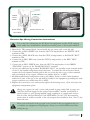
Electrical Installation Instructions for 220 Volt Models
1.To connect the electrical service, first remove the screws from the equipment compartment door. Carefully remove the access panel.
2. Locate the spa power pack. Loosen the screws on the front of the control box. Remove the
screws and the control box cover.
3. Input the electrical service from the GFCI breaker into the spa equipment compartment.
!
!
The GFCI breaker must be placed in sight of the spa, at a minimum distance
of five feet (1.5m) away.
As of January 1, 1996 the National Electric Code (NEC) requires GFCI
(Ground Fault Circuit Interrupter) on all spa installations.
4. Connect the supply conduit to the spa power pack.
16
A di ro nda ck Spa s ®
OWNER 'S M A N UA L
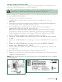
BOTTO M V I EW
O F BREAK ER
Factory
Installed
Neutral
(Pigtail)
Power to Spa
Neutral to Spa
Incoming
Ground (Green)
Incoming
Power (Black)
Ground to Spa
Outgoing Power to Spa
Outgoing Neutral to Spa
Incoming Power (Black or Red)
Incoming Neutral (White)
!
Electrical Spa Wiring Connection Instructions
!
Due to the risk of damaging the PC Board, the equipment and the GFCI tripping,
never, under any circumstances, should you connect power to the neutral terminal.
1. Identify the TB1 terminal block, located inside the spa power pack on the left side.
2. Connect the 8 AWG, WHITE wire, from the GFCI 50 amp breaker,to the WHITE "NEU"
terminal on TB1.
3.Connect the 8 AWG, BLACK wire, from the GFCI 50 amp breaker, to the BLACK "HOT"
terminal on TB1.
4. Connect the 8 AWG, RED wire, from the GFCI 50 amp breaker, to the RED "HOT"
terminal on TB1.
5. Connect the 8 AWG, GREEN wire, from the GFCI 50 amp breaker, to the GREEN
"GROUND" location on the "BONDING LUGS" terminal.
6. At least two additional lugs marked “BONDING LUGS” are provided on the external surface
of one of the bonded components metal enclosures. To reduce the risk of electrical shock,
connect the local common bonding grid in the area of the hot tub or spa to these terminals
with an insulated or bare copper conductor not smaller than No. 6 AWG.
7.All field-installed metal components such as rail, ladders, drains or other similar hardware
within 10 ft (3m) of the spa or hot tub shall be bonded to the equipment grounding bus with
copper conductors not smaller than No. 6 AWG.
8. Replace the control box cover and securely tighten the fastening screws. Close and secure the
equipment compartment panel.
!
!
!
!
Always use copper wire only (3 wire with ground; 8 gauge under 50ft, 6 gauge over
50ft)The electrical supply for this product must include a suitable rated switch or
circuit breaker to open all ungrounded supply conductors to comply with Section
422.20 of the National Electrical Code ANSI/NFPA 70-1987. The disconnecting
means must be readily accessible to the tub occupant but installed at least 5 feet (1.5m)
from tub water
Please review the back of the spa pack cover, located in the spa equipment bay, for
a complete spa equipment wiring diagram. Always use a licensed Electrician when
wiring the spa.
Ad iron d ac k S p as ®
OWN E R' S M AN UAL
17
11 0 / 2 2 0 VOLT CONVERTIBLE M OD ELS
• Keene (SE Model Only)
110 VOLT ELECTR I C A L RE Q U IRE M E NTS :
The above model is manufactured with the Adirondack Spas® 110V/220V convertible spa pack.
The unit is factory wired for 220 Volt applications with 4 kW heater operation. The model can
be converted for 110 Volt applications and to run with a 1 kW heater operation.
!
!
The 110 Volt model must be connected to a “dedicated” 110 Volt 20 Amp grounded
circuit. The term “dedicated” means the electrical circuit is not being used for any other
electrical items (lights, appliances, etc.). If the spa is connected to a non-dedicated
circuit, overloading will occur and nuisance tripping of the GFCI breaker switch at the
house breaker panel or GFCI cord will occur. Never connect the spa to an extension
cord due to the potential for fire from wires overheating.
The 110 Volt models may be optionally equipped with a GFCI power cord
(approximately 13 feet long). This model must be plugged into a grounding type,
110 Volt 20 Amp receptacle as shown below. No other electrical appliances or fixtures
should be used on this circuit.
CORR ECT
I N CO R R ECT
Dedicated 110V, 20A Receptacle
Dedicated 110V, 15A Receptacle
Data label amperage rating of 16 Amps must use
this type of 20 Amp dedicated receptacle and plug.
Do not use this type.
!
!
The use of any other receptacle or the connection of the plug to a 220 Volt service may
cause the spa pack to operate improperly, create the potential for an electrical hazard and
may void the spa warranty.
Adirondack Spas® models must be wired in accordance with all local electrical codes.
All electrical work should be done by an experienced, licensed electrician familiar with
spa installations.
Note: As of January 1, 1996 the National Electrical Code (NEC) requires a GFCI
(Ground Fault Circuit Interrupter) on all spa installations.
18
A di ro nda ck Spa s ®
OWNER 'S M A N UA L
INSTALLATI ON INS TRU C TIONS :
!
The following instructions are for the conversion of the Adirondack Spas® 110V/220V control
pack from a 220 Volt application to a 110 Volt application.
!
Due to the risk of equipment damage or fire, use only approved pressure-type wire
splicing lugs or connectors suitable for the size and type of wiring used.
Before servicing the spa, make sure all power to the spa is disconnected. Follow these instructions
for a successful electrical installation.
1. Unscrew the screws on the front access panel.
2. Carefully pull access panel toward you (away from spa) and pull upward. Set access
panel aside.
3. Locate the spa power pack. Loosen the screws on the front of the control box. Remove the
control box cover and the terminal block will be exposed.
4. Route the GFCI power cord through the vent hole in the base of the equipment
compartment and out from under the corner of the spa.
Note: 110 Volt installations require a 60Hz, single phase, two-wire electrical service plus
ground (Line 1, Neutral and Ground) and must be connected using a minimum supply
conductor ampacity of 20 Amps and a minimum GFCI circuit breaker size of 20 Amps.
5. Input the GFCI power cord to the terminal block inside the spa pack.
6. Connect the 8 AWG WHITE wire, from the power cord, to the WHITE "NEU" terminal
on TB1.
7. Connect the 8 AWG BLACK wire, from the power cord, to the BLACK "HOT" terminal on
TB1.
8. Connect the 8 AWG GREEN wire, from the power cord, to the GREEN "GROUND"
location on the "BONDING LUGS" terminal.
9. Connect jumper wire (jumper wire taped to the back of the spa pack) to J11 and J32. Red AC to White AC
10. Move dip switch #10 to the ON position. Special amperage rule "ON"
11. Replace the control box cover and securely tighten the fastening screws. Close and secure the
equipment compartment panel.
Note: Please review the back of the spa power pack cover, in the equipment bay, for a complete
spa wiring diagram.
Ad iron d ac k S p as ®
OWN E R' S M AN UAL
19
I N I TI A L O PERATING INS TRU CTIONS
Start-Up and Refill Procedures
Your Adirondack Spas® model has been tested at the manufacturing plant to ensure that all
of the spa functions operate. During the test procedure, a small amount of water may have
remained in the spa plumbing. Through the shipping process water may have spotted the spa
shell. You may need to wipe down the shell with a soft cloth. Please read and follow the start-up
instructions to ensure a successful start-up or refill.
!
!
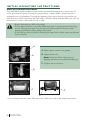
• Inspect and clean spa shell of any debris
• Do not turn power on to spa unless filled with water to appropriate level (See Page
21-22). The spa pack must never be operated without water in the spa; serious
damage to the heater and/or pump(s) may result.
• Do not fill spa with water before checking the items below (below items may become
loose in transit):
A
A. Hand tighten unions at the pumps
B. T
ighten drain valve
A
Note: The Drain Valve is left open for
shipping and must be closed before filling spa.
C. Tighten unions on heater
B
C
C
(LE)
C
C
(SE)
• Do not fill spa with hot water. This may cause a false error code to the temperature sensor.
20
A di ro nda ck Spa s ®
OWNER 'S M A N UA L
Start-up Procedures - SE Models
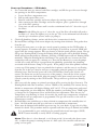
1. For a successful start-up, remove both filter cartridges, and fill the spa with water through
the openings in the filter compartment.
a.
b.
c.
d.
Locate the filter compartment area.
Pull up and remove filter cover.
Remove each filter cartridge and screen adapter by turning counter clockwise.
After removing the filter cartridges and screen adapters, place a garden hose through
one of the filter openings.
e. Turn water on and run water until it reaches a minimum level of 2” above the top of
the filters.
Note: Besides filling the spa to 2” above the top of the filter, all models will need to
be filled to 2” above the highest jet(s) in the spa. This is the minimum level allowed to
run the spa's circulation system, and/or jet pump(s).
2. Check all plumbing (clamps, unions and drain valve) connections for leaks.
3. Re-install filter cartridges and screen adapters by turning them clockwise. Exit garden hose
from the spa.
4. At this point turn power on to the spa control system by turning on the GFCI breaker. A
startup sequence of numbers will appear on the display. If no button is pressed, LINK will
appear after the startup sequence. Press any button to link the panel with the system. The spa
will go into Priming Mode. During the Priming Mode the heater will be disabled. Priming
Mode will end automatically in 4 minutes. (Pressing a TEMP button will exit Priming Mode
manually). When the Priming Mode ends Pump 1 low speed will start, however the water
temperature will not appear for a minute or so. Press the Jets Button(s) to turn the pumps
on and off to verify that all air is purged from the plumbing, particularly the plumbing
associated with the heater. (Pump 1 low speed). If the pump(s) have been primed continue
to next step. If the pump(s) have not primed after 2 minutes, and the water is not flowing
from the jets in the spa it may be necessary to manually prime the pump(s) by taking the
following steps: First turn the power off at the GFCI breaker. Next loosen, but do not
remove, the union nut on the top most area of the pump(s). Once all the air has escaped
tighten the union nuts back down. After the pump(s) have been vented, turn on the spa
control system by turning on the GFCI breaker. The spa will now go back into Priming
Mode.
5. After you verify the pumps are primed, turn them off by pressing the Jet(s) button(s). The
Priming Mode ends after 4 minutes, or Press TEMP to exit manually. The current factory
default set temperature will display flashing 80*F (26*C) (The set temperature and actual
water temperature are often different). While the numbers are flashing, Press TEMP again
to change the Set Temperature. Press and hold for faster adjustment. After the new Set
Temperature stops flashing, in about 10 seconds, the actual water temperature is displayed
again and the new set temperature is programmed. The spa will now heat to the new set
temperature as needed.
6. Re-install filter cover and allow spa to heat to desired set temperature; this normally takes 24
hours. 110 Volt models may take up to 48 hours to reach desired set temperature.
7. Water must be balanced and shocked upon start-up. See your dealer or pages 42-44 of this
manual for details. This procedure must be repeated each time the spa is drained and refilled.
!
!
It is recommended to press and release the ground fault circuit interrupter (GFCI)
RESET button monthly to verify GFCI is working properly.
Note: When there is a heat demand, a cool down period (30 seconds after heater turns
off ), or when the pump is running because of a filter cycle, the controller will turn the
pump on low speed.
Ad iron d ac k S p as ®
OWN E R' S M AN UAL
21
Start-up Procedures - LE Models
1. For a successful start-up, remove both filter cartridges, and fill the spa with water through
the openings in the filter compartment.
a. Locate the filter compartment area.
b. Pull up and remove filter cover.
c. Remove each filter cartridge and screen adapter by
turning counter clockwise.
d. After removing the filter cartridges and screen adapters,
place a garden hose through one of the filter openings.
e. Turn water on and run water until it reaches a
minimum level of 2” above the top of the filters.
Note: Besides filling the spa to 2” above the top of the filter, all models will need to be filled
to 2” above the highest jet(s) in the spa. This is the minimum level allowed to run the spa's
circulation system, and/or jet pump(s).
2. Check all plumbing (clamps, unions and drain valve) connections for leaks.
3. Re-install filter cartridges and screen adapters by turning them clockwise. Exit garden hose
from the spa.
4. At this point, turn on the spa control system by turning on the GFCI breaker. When your
spa is first actuated, it will go into Priming Mode, indicated by "Pr". During this mode
the heater is disabled to allow the priming process to be completed. As soon as "Pr" is
indicated on the topside panel, push the Jet(s) button(s) until the pump(s) are running in
high speed. If the pump(s) have been primed continue to step 5. If the pump(s) have not
primed after 2 minutes, and water is not flowing from the jets in the spa it may be necessary
to manually prime the pump(s) by taking the following steps: First turn the power off on
the GFCI breaker. Next loosen the union nuts on the pump(s). Allow for a small amount of
water and the trapped air to escape from the pump(s). Once all the air has escaped tighten
the union nuts back down. After the pump(s) have been vented, turn on the spa control
system by turning on the GFCI breaker. The spa will now go back into priming mode.
5. After the pumps are primed turn off by pressing the Jet(s) button(s). Next manually exit
the priming mode by pressing either the Warm or Cool button. After you have manually
exited the priming mode the display will show the set temperature, which defaults at
100° F/ 37°C, followed by two dashes (--). This will last for two minutes while the water
temperature is determined. Push the Warm or Cool button to the desired setting.
6. Re-install filter cover and allow spa to heat to desired set temperature: this normally
takes 24 hours.
!
7. Water must be balanced and shocked upon start-up. See your dealer or pages 42-44 of this
manual for details. This procedure must be repeated each time the spa is drained and refilled.
!
It is recommended to press and release the ground fault circuit interrupter (GFCI)
RESET button monthly to verify GFCI is working properly.
Important:
A pump should not be allowed to run without priming for more than 2 minutes. Under NO
circumstances should a pump be allowed to run without priming beyond the end of the 4
minutes priming mode. Doing so may cause damage to the pump and cause the system to go
into an overheat condition.
22
A di ro nda ck Spa s ®
OWNER 'S M A N UA L
J E T I D E NTIFIC ATIONS
VER SA-FLO™ JE T D E S C RIPTIONS
Cluster and Cluster Pulse Jet
The Cluster Jet provides a concentrated stream of water and
air for precise pressure point areas, while the Pulse version
provides a pulsating massage to the pressure point area
Mini Swirl Jet (Standard Jet)
The Mini Swirl Jet has an adjustable eyeball for directional
or rotational use. To change from directional to rotational,
with finger, simply adjust inner nozzle to the rotating
position.
Mini Twin Roto Jet (Standard Jet)
This jet provides multiple adjustment for various rotational
intensities. Adjust by spreading the nozzles apart.
XtraFlo Mini Jet (Deluxe Jet)
This jet provides a balanced mix of air and water to give a
soft, powerful, direct pressure massage to mid-size muscle
groups. The design allows for higher GPM for performance
and maximum relief.
XtraSwirl Mini Jet (Deluxe Jet)
A larger version of the Mini Swirl Jet, this jet gives a mid-size
rotational massage and pulsating massage. To change from
directional to rotational, with finger, simply adjust inner
nozzle to the rotating position.
Master-Flo™ Massage Jet
Multiple pressure point flow, provides foot and large muscle
relief. A larger version of the Veri-Flo Massage Jet, the
Master- Flo™ Jet delivers multiple pressure point flow into
several locations of muscle area and has an interchangeable
design that gives relief to a variety of areas.
CFE™ JET DESCRIPTIONS
Power Massage Plus® and Power Massage®*
Patented jet provides dual water massage to your neck or
back from under the built-in headrest. The jet is controlled
by a small selector valve, giving the bather total control.
* Provides a single ribbon of water flow parallel to the body, available on the Adirondack Spas® Models
Note: Not all jets are available in all models
Ad iron d ac k S p as ®
OWN E R' S M AN UAL
23
A D I RONDAC K SPA S ® VA LV E S
The jets in the Adirondack Spas® Line have different ways to adjust the jet therapy systems.
While having the Hydro Jet pump(s) on, the user has the ability to turn on and off each
individual Versa-Flo™ Jet. The Versa-Flo™ Jet(s) can be turned on and off by turning the outer
scallop on the face of the jet. In addition to having the ability to control each individual jet,
the jets can be adjusted by zones, by moving the Versa-Flo™ Micro Valve. The Versa-Flo™ Air
Control Valve controls the intensity of the jets by opening or restricting airflow.
Versa-Flo™ Valve
Versa-Flo™ Micro Valve
Versa-Flo™Air Control Valve
*Shown as LE Model
24
A di ro nda ck Spa s ®
OWNER 'S M A N UA L
EQ U I PME NT MAINTENANCE
Replacing the Spa’s Light Bulb
The spa’s light bulb is located inside the equipment compartment. Remove the front access
panel, by first removing the screws on the access panel. Then locate the light housing mounted
to the spa shell. Grasp the bulb holder on the back of the light niche. Turn bulb holder counter
clockwise to release it from the light niche. Pull bulb out of receptacle and replace it with a new
light bulb, available at your Adirondack Spas® dealer. Re-attach the light bulb holder to the
light niche by turning the light bulb holder clockwise.
CON T R O L PANEL FU NC TIONS - SE M OD ELS
MAIN CONTROL PANEL
Adirondack Spas® models are equipped with a main control panel located on the top collar of
the spa. The main control panel controls all of the spa functions.
The panel/topside will indicate the operations of the hydro jet pump(s), spa light, and water
temperature and will display the spa’s status regarding diagnostics, reminders and system
functions.
MAIN CONTROL PANEL NAVIGATION
The main control panel includes navigation, setting functions and modes (time of day,
temperature, filter cycles, light and preferences) activate or deactivate the hydro jet pump(s),
sensor related messages, reminder messages and diagnostic messages as well as much more.
Important - Please Read
Navigating the entire menu can be accomplished with the TEMP and the LIGHT buttons.
From this point on, the “WARM” and “COOL” will be referred to as TEMP button. TEMP
buttons are “action” buttons (changing temperature, flashing screen for further prompts,
changing preferences within a menu). The LIGHT button is a “choose” button (LED Lights on
and off, enters menus when numbers are flashing, scrolls through the menu, makes a selection).
Waiting for 10 seconds will return the panel to normal operation and a display of spa status.
Dual Temperature Control
This SE system incorporates Dual Temperature Range settings with independent set
temperatures. Your spa uses a HIGH RANGE (80*F – 104*F) or a LOW RANGE (55*F –
99*F) temperature adjustment. The HIGH RANGE would be primarily for a ready to use mode
of your spa, while the LOW RANGE can be utilized for a vacation mode or during non-use
periods.
HIGH RANGE is indicated on the display as RANGE
, the LOW RANGE
.
Temperature Adjustment
Press TEMP buttons (marked “Warm” or “Cold”) for desired set temperature. The numbers flash
during the temperature adjustment. Press LIGHT to return to main menu; or, the main screen
will return in 5 seconds. If the panel has only one TEMP button, the first TEMP button press
causes the temperature to flash, the second TEMP press causes the temperature to change, then
pressing LIGHT or waiting five seconds will return you to the main menu.
Ad iron d ac k S p as ®
OWN E R' S M AN UAL
25
If a Temperature button is pressed and held when the temperature is flashing, the temperature
will continue to change.
When the spa is first powered up the water temperature will not be displayed until the pump has
been running for at least two minutes. The Default Water Temp from the factory will be 80*F in
HIGH RANGE.
The temperature shown on the display without pressing the Warm or Cool button reflects the
temperature of the water at that particular moment.
HOLD Mode
“Hold Mode” is used to disable the pumps during service functions like cleaning or replacing the
filter. Press TEMP to desired hold temperature, Press LIGHT repeatedly to HOLD, then Press
TEMP to count down. The clock will count down from 60 minutes.
LOCK and UNLOCK Mode
Locking the panel prevents the spa from being used; it also prevents unwanted temperature
adjustments. All automatic functions are still active. Locking the temperature allows Jets and
other feature to be used, but the Set Temperature and other programmed settings cannot be
adjusted. Temperature Lock allows access to a reduced selection of menu items, which include
Set Temperature, FLIP, LOCK, UTIL, INFO and FALT LOG.
To engage LOCK MODE, Press TEMP, Press LIGHT repeatedly until LOCK appears, then
Press TEMP. To continue, Press LIGHT to toggle TEMP or PANL, Press TEMP to toggle ON
or OFF, then Press LIGHT to exit menu.
Note: To Unlock (UNLK) the above features, Press TEMP, then LOCK appears on
display, Press and hold TEMP while pressing LIGHT twice. UNLK screen appears, and
then will exit to main screen in approximately 3 seconds.
SETTING 24 HOUR CLOCK
This action changes a 12 hour clock to a 24 hour clock.
Press TEMP to initiate a flashing display. When the temperature is flashing, press LIGHT
repeatedly until PREF appears on the screen. When PREF appears, Press TEMP until F/C
appears. When F/C appears press LIGHT. When "24 and 12" hour appear, you then will press
TEMP to toggle between the two to select your choice.
Then Press LIGHT to:
1) enter choice.
2) again to exit PREF menu
3) again to exit UTL menu and return to main menu
TEMPERATURE F/C DISPLAY
Provides an option to choose between Fahrenheit and Celsius
To choose between Fahrenheit and Celsius, toggle between F and C in PREF menu. Press
TEMP, then Press LIGHT repeatedly until PREF appears, Press TEMP to toggle F/C choice,
Press LIGHT twice to exit to main menu.
26
A di ro nda ck Spa s ®
OWNER 'S M A N UA L
FLIP Button
Pressing the panel button marked FLIP will invert the display on the panel, allowing you to read
the display from inside or outside of the spa.
OPERATING THE HYDRO PUMP(S)/JET BUTTON(S)
Activate the hydro jet pump(s) for maximum hydrotherapy jet action. Press the “Jets1” button
once for low speed, twice for high speed and a third time to turn the pump off. If your spa has
two hydro jet pumps, “Jets1” will be a two speed pump, and “Jets2” will be a single speed pump.
Pressing “Jets2” once will turn the pump on high speed, pressing “Jet2” button again will turn
the pump off.
If either pump is left running, they will turn off automatically in 15 minutes if on High speed or
30 minutes if on Low Speed.
Also, note, if your spa is in READY MODE, pump 1 low speed may turn on for at least 1
minute every 30 minutes to detect the spa temperature (polling) and then to heat to the set
temperature if needed. When low speed turns on automatically, it cannot be deactivated from
the panel; however, the high speed may be started by pressing the “Jets1” button.
Clean-Up Cycle
When “Jets1” is manually turned on, a “Clean-Up Cycle” begins 30 minutes, on low speed,
after “Jets1” is turned off. If your spa is equipped with an Ozone Generator, it will operate with
“Jets1” on low speed.
Light Button - Saratoga Lighting System
The spa light is controlled using the LIGHT button. Press the LIGHT button once to turn on
the multiple color options and locations, then again to turn the lighting off. The LIGHT button
is also used in conjunction with temperature(s) to navigate the system menus.
Optional Splash™ Lighting
If your spa is equipped with Splash™ Lighting systems, see the operational features and
directions located in the Splash™ box, or contact your dealer for instructions.
Ad iron d ac k S p as ®
OWN E R' S M AN UAL
27
SE - HEATING MODES
There are two Heating Modes in the SE spa, described as READY and REST.
READY Mode will allow the spa to “Poll” (circulating the water every 30 minutes to sense the
temperature) and determine a need for heat. The Panel will maintain a “current” temperature
display.
-READY Mode maintains a constant water temperature. It will circulate water every
30 minutes, heat as needed in order to maintain a constant set water temperature using
Pump 1 Low Speed and refresh the temperature display.
REST Mode will not “Poll” and will only heat during filter cycles. The panel will not display a
current temperature until Pump 1 has circulated for a minute or two.
-REST Mode will only allow heating during programmed filter cycles. In REST Mode
it won’t circulate every 30 minutes to sense the water temperature, so the temperature
display may not show a current temperature until the filtration pump has been running
for a minute or two.
Choosing Between Ready and Rest Mode
Press the TEMP button, then the LIGHT button repeatedly until MODE appears. Pressing the
TEMP button will toggle between SET READY and SET REST. Choose one, and then Press
LIGHT to set and exit.
If the filtration pump has been off for an hour or more, and when any function button (except
Light) is pressed on the panel, the pump used in conjunction with the heater will run so that the
temperature can be sensed and displayed.
In REST Mode the screen will display [RUN][PUMP][FOR][TEMP] if the filtration pump has
not run for over 1 hour.
Note: The Filtration pump noted in the SE Heating Modes section refers to Pump 1 on the SE
Systems, operating on low speed.
28
A di ro nda ck Spa s ®
OWNER 'S M A N UA L
SE - FILTER CYCLE MODES
Filter Cycles are set using a start time and duration. Start Time is indicated by an “A” for AM
and a “P” for PM in the bottom right corner of the display. The Duration setting has no “A” or
“P” indicator.
The Cycles and the Duration settings can be adjusted in 15-minute increments. The panel
calculates the end time and displays it automatically. You have two Cycles you can adjust. The
spas default is one cycle per day. If you choose to have only one cycle the duration should be in
the 4 to 6 hour range as a minimum.
Based on your spa use, you may need to operate two cycles per day. The more the spa is used the
longer the filter cycles should operate. Start with two, 2-Hour filter cycles and adjust up or down
as you observe the use pattern of the spa. The cycles are identified by “FILT1” and”FILT2”.
Duration and Start Times of Filter Cycles
To customize your filter cycles and times, start by Pressing TEMP.
•
While the temperature is still flashing Press LIGHT repeatedly until FLTR1 appears
flashing. (If you press the LIGHT button one more time it will take you to FLTR2)
•
Press the TEMP button to advance to the beginning of the time setting process for
filtration.
•
Pressing TEMP will advance to first screen to change time for F1 and “BEGN” (Begin) will
appear on screen.
•
Press TEMP, and hour will flash; Pressing TEMP will change the hour.
•
Press LIGHT to advance to minutes, and then Press TEMP to change minutes. Minutes
advance in 15 minute intervals.
•
Press LIGHT to set Run Hours (the actual start time of the cycle)
•
Press TEMP to begin the hour change, each TEMP press will move time of day one hour.
•
Press LIGHT to advance the minutes in 15 minute increments.
•
Press LIGHT when finished.
The read out scrolls the information that is now programmed; F1 ENDS 12:45A.
Repeat this process to create the FLTR2 cycle if desired.
Press TEMP to exit to main screen.
Ad iron d ac k S p as ®
OWN E R' S M AN UAL
29
Continuous Filtration Non-Circulation Pump
To set a continuous filtration, set Filter 1 to begin at a specified time as listed above. Because
you will be running the Pump 1 low speed continuously, any start time will be fine, as the start
and end time will be the same. Remember that your cost of operation will increase by operating
Pump 1 on low speed as continuous filtration.
{Example: Start time: 8am - End time: 8am = 24-Hour Circulation}
Then set the duration as listed above, advancing the duration hours to 24. The FLTR2 cycle start
time, 12 hours after the FLTR1 start time will only engage the Purge Cycle. The end time for
FLTR2 in this setting will be unavailable with 24-Hour duration.
* When Pump 1 low is operating and an ozone generator is installed, they will operate together.
*Default factory setting is one filter cycle set to run in the evening (assuming the time of day is
properly set). The second filter cycle can be enabled as needed.
*At the start of each filter cycle Pump 2 (if one is present) will run briefly to purge its plumbing
to maintain water quality.
30
A di ro nda ck Spa s ®
OWNER 'S M A N UA L
SE – R E M I NDER MES S AG ES
Reminder Messages help in the general maintenance of the spa. You can suppress these messages
through the PREF Menu. Press TEMP to initiate a flashing display, then Press LIGHT
repeatedly until PREF appears, then Press LIGHT until “Reminders” scrolls across screen, then
Press TEMP for options, TEMP toggles between “ NO” and “YES”, then Press LIGHT to exit
the PREF menu, Press LIGHT 3 times to return to MAIN menu. To reset a displayed reminder
message, Press a TEMP button.
The Reminder options are as follows;
•
Check PH displays CHEK PH every 7 days
•
Check Chemistry displays CHEK CHEM every 7 days
•
Clean Filter displays CLN FLTR every 30 days
•
Test GFCI displays TEST GFCI every 30 days
•
Change Water displays CHNG WATR every 90 days
•
Clean Cover displays CLN COVR every 180 days
•
Treat Wood displays TRT WOOD every 180 days (Saratoga Spas® uses a
thermoplastic, low maintenance cabinet, not wood)
•
Change Filter displays CHNG FLTR every 365 days
•
Change Cartridge displays CHNG CART as needed. (This refers to a
Mineral Cartridge, see Dealer for details)
Note: These are guidelines and reminders and do not override the user’s responsibility to
maintain their spa. The more the spa is used, the more care the water will require. The harsher
the climate you live in, the more care the exterior features of the spa will need.
Not all Reminders will be relevant to your spa, ask your Dealer regarding details that may
pertain to your spa.
Ad iron d ac k S p as ®
OWN E R' S M AN UAL
31
CON TR OL PA NEL FU NCTIONS - LE M OD ELS
MAIN CONTROL PANEL
The panel/topside will indicate the operations of the hydro jet pump(s), spa light, water
temperature and will display diagnostic symbols.
Adirondack Spas® models are equipped with a main control panel located on the top collar of
the spa. The main control panel controls all of the spa functions. It displays the spa’s status and
any diagnostic messages. The main control panel and digital display are illuminated by a light
from the inside of the panel.
MAIN CONTROL PANEL BUTTONS AND DIGITAL DISPLAY
The main control panel has buttons which the spa user presses to set the temperature, vary the
intensity of the light and activate or deactivate the hydro jet pump(s). The control panel also has
a digital display that displays the spa diagnostics (i.e.: temperature setting, jet functions or error
messages).
Temperature Control
The set temperature range is from 80°F (26°C) to 104°F (40°C). The temperature of the spa
water will automatically be 100°F (37°C) the first time that power is applied. This is the default
temperature setting programmed at the factory.
To display the set temperature of the spa, press the Warm or Cool button once.
To raise the set temperature of the spa, press the Warm button a second time. Each press of the
Warm button will continue to raise the set temperature.
To lower the set temperature of the spa, press the Cool button a second time. Each press of the
Cool button will continue to the lower set temperature.
Note: When first powered up the water temperature will not be displayed until the pump has
been running for at least two minutes.
Note: The temperature shown on the display without pressing the Warm or Cool button
reflects the temperature of the water at that particular moment.
32
A di ro nda ck Spa s ®
OWNER 'S M A N UA L
OPERATING THE HYDRO PUMPS ON LE MODELS
Jets 1 Button
Activates the hydro jet pump #1 for maximum hydrotherapy jet action. Press the Jets 1
button once for low speed, again for high speed and again to turn the pump off. When the
pump is activated the indicator above the Jets 1 button will light up. The pump will turn off
automatically after 15 minutes on high speed and 4 hours on low speed.
Jets 2 Button
Activates the hydro jet pump #2 for maximum hydrotherapy jet action. Press the Jets 2 button
once for high speed and again to turn the pump off. When the pump is activated the indicator
above the Jets 2 button will light up. The pump will turn off automatically after 15 minutes on
high speed.
Note: The spa light will begin flashing 15 seconds before the pumps shut off as a reminder,
that the pump(s) cycle is about to end.
Note: The Keene, Champlain and Caroga models have only one jet pump button on the
panel.
Note: Adirondack Spas® are designed for maximum heat retention. The unit is not designed
to cool water. If the set or desired temperature is below that of the ambient temperature, the
unit will not be able to achieve this demand. Depending on the desired temperature, it may be
necessary to add cool water to the unit to lower your spas water temperature.
Light Button - Saratoga Lighting System
The Saratoga Lighting System is designed to give the user multiple color options and styles.
To turn on the system, press the light button. The spa will illuminate with one of it's many
combinations and locations. As you continue to press the light button, different color
combinations and illuminating styles, such as solid, fading or pulsating color will function.
You must press the light button through each function before it reaches the off mode. If the
light is left on it will automatically be turned off by the control system after four hours of
continuous operation.
Optional Splash™ Lighting
The Splash™ Lighting is used in conjunction with the Saratoga Lighting system and increases
the illumination location. See the operational features and directions located in Splash™ box, or
contact your dealer for instructions.
Ad iron d ac k S p as ®
OWN E R' S M AN UAL
33
LE - HEATING MODES
Mode is changed by pressing the Warm or Cool button, then pressing the Mode button. The
heating modes "do not" control the circulation pump. It only controls the way the spas will heat
and during what time of day.
Standard Mode is programmed to maintain the desired temperature continuously,
thermostatically on a daily basis. Note that the last measured spa temperature displayed is
current only when the pump has been running for at least 2 minutes. "Std" will be displayed
momentarily when you switch into Standard Mode.
Economy Mode heats the spa to the set temperature only during your chosen economy
mode cycles, as needed. "Ecn" will display solid when temperature is not current, and will
alternate with temperature when temperature is current. You can choose 2, 4, 6 or 8 hours of
heat option during a 12 hour time frame. If you choose 2 hours on then the heat option will be
off for 10 hours. Then on for 2, then off for 10, and so on. This is not a filtration cycle but a
time frame you choose to allow the spa to heat if needed.
Sleep Mode heats the spa within 20°F/10°C of the set temperature only during filter cycles.
"SLP" will display solid when temperature is not current, and will alternate with temperature
when temperature is current. This cycle is designed when the spa will not be used for long periods
of time. Water sanitizing and balance will still be necessary even if the spa is not being used.
Note: The last measured spa temperature displayed is current only when the pump has been
running for at least 2 minutes.
LE - FILTER CYCLE MODES
Adirondack Spas® has designed its continuous circulation pump system to operate without
manual programming. The continuous circulation pump operates unless interrupted by a system
diagnostic or automated program, or by a power failure. With the continuous circulation system,
manual filter cycles do not apply. The spa is designed to continuously circulate the water.
Freeze Protection
If the temperature sensors detect a drop to below 44°F/6.7°C within the heater, the pumps will
automatically activate to provide freeze protection. The equipment stays on until 4 minutes after
the sensors detect that the spa temperature has risen to 45°F/7.2°C or higher.
Summer Set Mode
Your spa is equipped with this feature to prevent heat build up. Summer Set Mode is activated
when the water temperature exceeds the set temperature by 3°F. When the Summer Set Mode is
activated it will suspend the filter cycle for 30 minutes, then Pump 1 will run on low speed for 2
minutes. It will continue this way until the water temperature returns to the set temperature.
Automated Purge Cycle
Every 12 hours the Jet Pump(s) will engage. Pump 1 on low speed, and on selected models
Pumps 2 and Pumps 3 on high speed for a duration of 5 minutes. This process purges the jet
plumbing lines twice daily, making sure water in the plumbing lines is moved out into the spas
main body of water.
34
A di ro nda ck Spa s ®
OWNER 'S M A N UA L
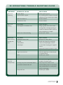
SE - DI AGNO S TIC MES S AG E S
Scroll Message
Meaning
Action Required
NO COMM
The panel is not receiving communication from the system
Call for Service
---*F ---*C
Temperature unknown
After pump has run for 1 minute, the
temperature will be displayed
HTR TOO HOT
(OHH)
One of the water temp sensors has detected 118*F
(47.8*C) in the heater and the spa is shut down.
DO NOT ENTER THE WATER.
Remove the spa cover and allow water
to cool. Once the heater has cooled,
reset by pushing any button. If spa
does not reset, shut off the power to
the spa and call your dealer or service
organization.
WATR TOO HOT
(OHS)
One of the water temp sensors has detected spa water
110*F(43.3*C) and spa functions are disabled.
DO NOT ENTER THE WATER.
Remove the spa cover and allow water
to cool. At 107˚F/42˚C, the spa should
automatically reset. If spa does not
reset, shut off the power to the spa and
call your dealer or service organization.
42*F TOO COLD
A potential freeze condition has been detected or Aux
Freeze Switch has closed
All pumps are activated automatically
& stay on at least 4 minutes after
potential freeze condition has ended
or aux freeze switch opens. This is
an operational message, not an error
indication.
102F SNSR
BALANCE
Temperature sensors MAY be out of sync by 2*F or 3*F
Call for Service
SNSR SYNC
Temperature sensors ARE out of sync. The Sensor Balance
is Poor. Fault has been established for at least 1 hour.
Call for Service
SNSR A
A temperature sensor or sensor circuit has failed
Call for Service
SNSR B
A temperature sensor or sensor circuit has failed
Call for Service
HTR FLOW
LOSS (HFL)
There may not be enough water flow through the heater to
carry the heat away from the heating element. Heater startup will begin again after 1 minute.
See FLOW RELATED CHECKS
below
HTR FLOW FAIL
(LF)
There IS NOT enough water flow through the heater
to carry the heat away from the heating element and the
heater has been disabled. After the problem is resolved, you
must press any button to reset and begin heater start up.
See FLOW RELATED CHECKS
below
HTR MAY BE
DRY (dr)---WAIT
POSSIBLE dry heater, or not enough water in the heater
to start it. The spa is shut down 15 min. Press any button
to reset the heater start-up.
See FLOW RELATED CHECKS
below
HTR DRY
There IS NOT enough water in the heater to start it. The
spa is shut down. After the problem has been resolved, you
must press any button to reset and restart heater start-up.
See FLOW RELATED CHECKS
below
102T
Control System is in Test Mode
Call for Service
PRES BTTN TO
RSET
Some errors may require power to be removed and
restored. A reset message may appear with other messages
Press button to reset
HOT FALT
A pump appears to be stuck ON, a serious condition that
COULD result in overheated spa water
Call for Service
*Please contact your Dealer for the following messages: MEM FAIL, MEM RSET, CNFG FAIL, STUK PUMP*
Note: Start-up Procedures –SE Models page 21 in current Adirondack OM
FLOW RELATED CHECKS Check for low water level, suction flow restrictions, ensure filters are clean, closed valves, trapped air, too many closed jets
and pump prime.
On some systems even when the spa is shut down, some equipment may occasionally turn on to continue monitoring
temperature or if freeze protection is needed.
All messages may not appear on your panel display.
Ad iron d ac k S p as ®
OWN E R' S M AN UAL
35
L E - DI AGN O S TIC MES S AG ES
Scroll Message
Meaning
Action Required
No message on display. Power has been cut off to
the spa.
The control panel will be disabled until power
returns. Spa settings will be preserved until next
power up.
--
Temperature unknown.
After the pump has been running for 2 minutes, the
temperature will be displayed.
OHH
"Overheat." The spa has shut down. One of the
sensors has detected 118˚F/48˚C at the heater.
DO NOT ENTER THE WATER. Remove the spa
cover and allow water to cool. Once the heater has
cooled, reset by pushing any button. If spa does not
reset, shut off the power to the spa and call your
dealer or service organization.
OHS
"Overheat." The spa has shut down. One of
the sensors has detected that the spa water is
110˚F/43˚C.
DO NOT ENTER THE WATER. Remove the spa
cover and allow water to cool. At 107˚F/42˚C, the
spa should automatically reset. If spa does not reset,
shut off the power to the spa and call your dealer or
service organization.
ICE
"Ice." Potential freeze condition detected.
No action required. The pump and blower will
automatically activate regardless of spa status.
SnA
Spa is shut down. The sensor that is plugged into
the Sensor "A" jack is not working.
If the problem persists, contact your dealer or service
organization. (May appear temporarily in an overheat
situation and disappear when the heater cools.)
Snb
Spa is shut down. The sensor that is plugged into
the Sensor "B" jack is not working.
If the problem persists, contact your dealer or service
organization. (May appear temporarily in an overheat
situation and disappear when the heater cools.)
SnS
Sensors are out of balance. If alternating with spa
temperature, it may just be a temporary condition.
If flashing by itself, spa is shut down.
If the problem persists, contact your dealer or service
organization.
HFL
A significant difference between temperature
sensors has been detected. This could indicate a
flow problem.
Check water level in spa. Refill if necessary. If the
water level is okay, make sure the pumps have been
primed. If problem persists, contact your dealer or
service organization.
LF
Persistent low flow problems. (Displays on the fifth
occurrence of "HFL" message within 24 hours.)
Heater is shut down, but other spa functions
continue to run normally.
Follow action required for "HFL" message. Heating
capability of the spa will not reset automatically; you
may press any button to reset.
dr
Possible inadequate water level, poor flow, or air
bubbles are detected in the heater. Spa is shut down
for 15 minutes.
Check water level in spa. Refill if necessary. If water
level is okay, make sure the pumps have been primed.
Press any button to reset, or this message will
automatically reset within 15 minutes. If problem
persists, contact your dealer or service organization.
drY
Inadequate water level detected in heater. (Displays
on third occurrence of "dr" message.) Spa is shut
down.
Follow action required for "dr" message. Spa will not
automatically reset. Press any button to reset.
Note: "Pr" reading see page 22 for LE Models.
FLOW RELATED CHECKS -
Check for low water level, suction flow restrictions, ensure filters are clean, closed valves, trapped air, too many closed jets
and pump prime.
On some systems even when the spa is shut down, some equipment may occasionally turn on to continue monitoring
temperature or if freeze protection is needed.
All messages may not appear on your panel display.
36
A di ro nda ck Spa s ®
OWNER 'S M A N UA L
S PA C A R E AND WATER MA INTENA NCE
GENERAL INFORMATION
Adirondack Spas® are manufactured from the highest quality, most durable materials available
today. We recommend that a spa maintenance program be followed. The care you take will
ultimately determine how long your spa or its individual components will last. This section will
help you maintain your investment.
Replacing The Water
Proper spa maintenance (regular draining and replacing of spa water according to these
directions along with filter cleaning), proper spa water treatment (water balance and maintaining
correct sanitizer levels), and proper installation (adequate ventilation) are the keys to ensuring
sanitary, healthy spa water.
It is recommended that you completely drain your spa every 45 to 90 days. Normally, after a
period of time the water will become sudsy and harder to maintain and should be replaced. The
IPSE WRI, Water Replacement Interval Formula is as follows:
WRI = .33 X Spa Volume in US Gallons
Average Bathers per Day
Note: Heavy usage may require more frequent draining.
To Drain Your Spa:
1. Disconnect the spa from the power supply by tripping the GFCI breaker located in the
house breaker panel or at the GFCI disconnect breaker at the spa.
2. Take off the equipment access panel by first removing the screws and then pulling out the
access panel. Locate main drain valve and attach the inlet of a garden hose to the drain
valve. Route garden hose to an appropriate draining area away from the spa to avoid
flooding of the surroundings around the spa.
Note: Spa water with a high sanitizer level may harm plants and grass.
3. Open the drain valve by turning the knob. The spa will drain by gravitational flow.
4. Adirondack Spas® will drain to the lower suction fittings in the footwell of the spa. It may
be necessary to vacuum or sponge up a small amount of the remaining water in the spa.
5. When empty, inspect the spa shell and clean as required.
6. Close the drain valve and remove garden hose.
7. Replace or close the equipment access door and replace screws.
8. Refill the spa through the filter compartment BEFORE restoring power.
Important:
Always clean the filter cartridges each time the spa is drained for cleaning.
Ad iron d ac k S p as ®
OWN E R' S M AN UAL
37
Filter System
Adirondack Spas® are equipped with two standard filter cartridges. As with any filtering system,
the filter cartridges may become clogged with particles, body oils or calcification resulting in
poor water quality and reduced water flow. It is important to maintain a clean, unobstructed
filtering system. A reduced water flow may cause a failure of the filter cycles to operate due to
the pump shutting down. If the circulation of water stops during sub-freezing temperatures and
goes unnoticed, the spa water may freeze, which is not covered under manufacturer's warranties.
Important:
The frequency and duration of use, and the number of occupants, all contribute to determining the
appropriate time between filter cleanings. More use means that more frequent filter cleanings are
required. Failure to maintain the cartridges in a clean, unobstructed manner will result in reduced
water flow. Any damage to the spa due to freezing or caused as a result of poor maintenance will
not be covered by your spa warranty.
FILTER CARTRIDGE REMOVAL AND CLEANING
1. Disconnect the spa from the power supply by tripping the GFCI breaker at the spa.
2. Remove and carefully set aside the filter compartment cover.
3. Remove any floating items from within the filter compartment.
4. Grasp the handle of the filter cartridge and turn the cartridge clockwise until it is free from the base retainer. Leave screen adapter in place.
5. Place the cartridge on a clean surface and spray with a garden hose. It will be necessary to rotate the cartridge(s) to ensure all the filter pleats have been cleaned.
6. Continue cleaning by spraying down throughout the center of the cartridge (inside out).
7. For a complete and more thorough cleaning it is recommended to soak cartridges in a filter cleaning solution. Follow directions on the filter cleaner label.
8. Before inserting cartridges, do a final inspection of the cartridges.
9. To reinstall the filter cartridges, reverse the order in which the cartridges were removed.
Important:
Do not turn power on or use the spa with the filter cartridges or screen adapters removed.
Note: Spa cartridges are a disposable item and should be replaced each year, at a minimum.
CARE OF THE SPA PILLOWS
The spa pillows used on Adirondack Spas® models will provide years of comfort if treated with
care. To extend their life the spa pillows should be removed and cleaned. Wash with a mild soap
and water solution. ALWAYS rinse off the spa pillows thoroughly to remove any soap residue. If
the spa is not going to be used for a long period of time the spa pillows should be removed until
the next spa use.
To remove and replace the spa pillows:
1. Carefully lift one end of the pillow away from the spa shell.
2. Continue lifting one end until it is released from the attachment bar on the spa shell. Do
the same to loosen the other end of pillow.
38
A di ro nda ck Spa s ®
OWNER 'S M A N UA L
3. To reinstall the spa pillow, carefully bend the pillow slightly to allow the slit on the back
of the pillow to slip over the attachment bar retainer on the spa shell.
4. After the pillow slips over the attachment, press the pillow down into the recess in the
spa shell.
Important:
Just pulling the pillow straight up and off of the attachment bar will eventually damage the
pillow. This abuse is not covered under warranty.
CARE OF THE EXTERIOR
Spa Shell
Adirondack Spas® are manufactured with a tough acrylic surface. Some staining or water
marking may occur at or above the water surface. Removal of these surface conditions can
usually be accomplished with a soft cloth by merely wiping them away. Stubborn stains can be
removed first by draining the spa and then using a nonabrasive product. Always thoroughly
rinse off any spa shell cleaning agent with fresh water.
!
!
Keep all cleaners out of the reach of children and use care when applying.
Spa Cabinet
The skirt around the Adirondack Spas® models are manufactured with the finest quality
material and is available in a low maintenance exterior.
WeatherAll™ Skirt
The WeatherAll™ skirt combines the durability of plastic with the look of professionally
finished wood. To remove any stains or dirt simply spray the skirt with water and wipe down
with a soft cloth. WeatherAll™ is not designed to be stained or resealed.
Note: WeatherAll™ could experience natural fading due to sunlight and weather exposure.
This condition is not covered under warranty.
CARE OF THE SPA COVER
Vinyl Cover
Your vinyl thermal spa cover has been designed for your particular spa. Monthly cleaning and
conditioning is recommended to maintain its beauty.
To clean and condition the vinyl cover:
1. Remove the cover from the spa and gently lean it against a wall or fence.
2. With a garden hose, spray the cover to loosen and rinse away dirt or debris.
3. Using a large, non-abrasive sponge and using a very mild soap solution (one teaspoon dish
washing liquid with two gallons of water) scrub the vinyl top in a circular motion. Make
sure to rinse all soap off the cover before it dries.
4. Scrub the cover’s perimeter and side flaps. Rinse clean with water.
5. Rinse off the underside of the cover with water only (use no soap), and wipe it clean with
a dry rag.
6. To condition the cover after cleaning, apply a thin film of saddle soap (follow directions on
the container) or vinyl conditioning cream.
Ad iron d ac k S p as ®
OWN E R' S M AN UAL
39
Important reminders:
• Do unlock and release all cover locks before attempting to open cover.
• Do remove snow buildup to avoid damage of the foam core from the additional weight of the
snow (not covered under warranty).
• Do lock cover lock straps to secure the cover when the spa is not in use.
• Do not drag or lift the spa cover using either the flaps, or the cover tie downs.
• Do not walk, stand, or sit on the cover.
Important:
Whenever the spa is not in use it is essential that the thermal cover be kept in place. When
filled this ensures effective temperature maintenance and economical operation. When empty
this prevents potential damage to the spas surface finish that can result from excessive heat
caused by the sun. This type of damage is specifically excluded from warranty protection. It is
recommended that the thermal cover tie downs always be used to discourage access to the spa by
unsupervised children and minimize heat loss.
*The spa cover manufacturer handles all warranty claims. Adirondack Spas® does not handle
any warranty issues on the spa cover. Every Adirondack Spas® is equipped with a locking cover
that meets the ASTM F1346-91 standard for safety covers.
WINTERIZING YOUR SPA
If you chose not to use your Adirondack Spas® model during the winter, it is recommended to
properly winterize your spa. Any damage occurring due to accidental freezing of the spa is not
covered under warranty.
The following steps are designed to protect your spa from freezing if followed. For ultimate
protection against freeze damage to your spa, contact your local Adirondack Spas® Dealer to
schedule a winterizing service plan.
1.
2.
3.
4.
Turn power off to the spa. Trip GFCI breaker.
Unscrew panel screws. Remove access panel.
Locate the drain valve and attach a garden hose to the drain valve.
Open the drain valve and allow the water to drain (Adirondack Spas® will drain to the
drain fitting in the footwell of the spa).
5. Remove filter cartridges and screen adaptors. Clean and store in a dry place.
6. Using a wet/dry Shop Vac vacuum, soak up the water remaining on the bottom of the spa.
7. Open unions at the heater and at the pump(s). Remove pump(s) from spa. Vacuum water
from return and suction sides of the plumbing on the pump(s). Vacuum any water from
heater housing. Leave unions at the heater and at the pump(s) open.
8. Reverse vacuum and blow out each line of the plumbing going into the pump(s).
Important:
Do not use ethylene glycol based antifreeze. This type of antifreeze is toxic and can damage
the spa surface.
40
A di ro nda ck Spa s ®
OWNER 'S M A N UA L
9. Place the vacuum hose down the filter cartridge openings and vacuum any water from
filter compartment.
10. With a shop vac, go to every jet in the spa (including suction fittings) and place vac hose over the face of every jet and vacuum out any water left in the lines. Reverse vac hose and force air through each jet.
11. Wipe down spa shell with a soft clean cloth.
12. Place spa cover over spa and lock into place.
13. To restart the spa, connect all hoses and close all unions. Once all the hoses, jet valve assemblies, and pump unions are reattached, follow the normal fill-up procedures. It may be necessary to flush the spa depending on the amount of antifreeze used.
Note: It may be necessary to lubricate o-rings and gaskets for a positive seal. Use only
Adirondack Spas® approved lubricants, contact your local dealer for more information.
Important:
If these instructions are not followed, damage due to freezing water in the plumbing lines may occur
and is not covered under manufacturer's warranty.
* Not available on the Adirondack Spas® SE Line. The two speed jet pump is used on low speed
during filtration cycles.
Ad iron d ac k S p as ®
OWN E R' S M AN UAL
41
WATE R QUA LITY MAINTENANCE
General Information
As the owner of an Adirondack Spas® model, endless hours of entertainment, recreation, and
relaxation await you. Caring for your spa will become a routine and pleasant part of your daily
activities. You will be able to maintain your spa water and keep your spa equipment in excellent
condition. To do so you first must balance your spa’s water.
Balanced Water
Balanced water ensures spa bathers safety as well as protecting the spa heater and components
from corrosion. Also, balanced water protects the spa surface from unsightly scale deposits,
which reduce the efficiency of the spa equipment. You can obtain balanced water by correctly
adjusting a few chemical components in the water. Specifically, you will need to adjust the pH,
total alkalinity and calcium hardness
Note: Improper water chemistry can result in product failure and invalidate your warranty.
pH
pH is measured on a scale that runs from 0-14. pH indicates whether water is neutral, acidic,
or basic. The drawing below shows a pH equal to 7.0 is neutral. A pH below this point is acidic
and a pH above this point is basic. Test pH weekly.
Recommended Range - 7.2 to 7.8
If the pH is too low it can
1. Corrode metal surfaces.
2. Use excess sanitizer.
3. Irritate bathers’ skin and eyes.
If the pH is too high it can
1. Deposit scale on surfaces.
2. Contribute to cloudy water.
3. Cause eye irritation.
4. Reduce sanitizer efficiency.
Adjusting pH To raise pH add a granular pH Increaser or sodium carbonate at the rate suggested on the
container. To lower pH add a granular pH Decreaser, or sodium bisulfate at the rate suggested
on the container. After initial application, allow water to circulate approximately 20 minutes
on Jets 1 at high speed. Test pH and add second dose if required. (Adirondack Spas® Jets 1
operates 15 minutes)
Total Alkalinity
There are minerals in your spa water that act as buffering agents. Total alkalinity is the
measurement of these alkaline materials that help prevent corrosion and staining. The correct
amount of alkalinity in your spa water will keep the water’s pH consistent while allowing for
economical pH adjustment when necessary.
42
A di ro nda ck Spa s ®
OWNER 'S M A N UA L
Example: At low total alkalinity levels, the water’s pH easily drifts, making frequent pH
adjustments necessary and the added expense of multiple chemical treatments.
On the other hand, a high total alkalinity level keeps the water pH rigidly fixed. If pH
adjustment is necessary, you will need unusually large amounts of treatment chemicals
to change the water’s pH.
Recommended Range: 80 to 120 Parts Per Million (PPM)
Potential Problems:
1. pH difficult to maintain. If total alkalinity is too low, pH will drift.
2. Corrosive tendencies. If total alkalinity is too high:
• pH difficult to adjust (it remains fixed.) • Cloudy water.
Note: The use of Biguanide,
• Potential for scaling.
Salt generators and other after
• High pH and low sanitizer efficiency.
market sanitizer/ disinfectant
systems may damage components
and void your spa's warranty.
TESTING WEEKLY
Adjusting Total Alkalinity
Total Alkalinity can be raised with Alkalinity Increaser, or sodium bicarbonate at the
manufacturer’s recommendation for dosage.
Calcium Hardness
Calcium hardness is the amount of dissolved calcium in your spa water. Too little calcium in the
water will etch plaster surfaces, too much will leave deposits on surfaces and equipment.
Recommended Range: 125-150
Potential Problems:
Calcium Hardness Too Low
Calcium Hardness Too High
• Some surfaces may be etched.
• May contribute to cloudy water.
• May lead to equipment corrosion.
• Scaling of surface, piping and equipment.
Adjusting Calcium Hardness
Raise hardness by the addition of calcium chloride. Decrease calcium hardness by draining spa
and replacing with water containing lower levels of calcium hardness.
Disinfectant
• Brominating Tablets, Granular Bromine and Granular Chlorine are popular disinfectants and
are particularly well suited to compliment your ozone purification system spa. They are also
very suitable products in water with elevated temperatures.
• Brominating Tablets and Granular Bromine are effective as a spa water sanitizer and
disinfectant. Follow manufacturer’s directions for proper dosage. It is recommended to
maintain an active bromine residual of 2.0 to 4.0 ppm.
• Granular Chlorine (Dichlor Dihydrate, Lithium Hypochlorite), is designed to dissolve
quickly and completely, provide a steady source of available chlorine to control the growth
of algae, kill bacteria and destroy organic contaminants. It is recommended to maintain
a chlorine residual of between 1.0 and 3.0 ppm. Non-Chlorine type shock will oxidize or
destroy most of the organic contaminants that result from bather load. This quick acting
oxidizing shock treatment goes to work almost immediately improving water quality and
eliminating irritating wastes and odor. This product is intended to be a shock treatment
only, and is not a disinfectant.
Ad iron d ac k S p as ®
OWN E R' S M AN UAL
43
Shock Treatment with Granular Disinfectant
Adding granular chlorine or bromine disinfectant to the water in amounts much larger than
normal is called “shocking” the spa and should not be confused with non-chlorine shock. An
occasional shock treatment destroys algae, bacteria, and chloramines. After shocking your spa,
do not allow bathers to enter the spa until disinfectant levels drop to normal.
What Causes Loss of Disinfectant?
•Algae: The presence of algae will consume large amounts of disinfectant. If you have an algae
problem, the use of an algaecide in addition to disinfectant may be necessary.
•Bather Load: The greater the number of people using your spa, the more disinfectant you will
need to use.
•Improper pH: A high pH above 7.8 substantially retards disinfecting. Keep the pH between
7.2 and 7.8.
•Sunlight: The sun’s Ultraviolet (UV) rays readily dissipate disinfectant levels.
•Water Temperature: High water temperature accelerates the loss of disinfectant.
•Weather: Rain and wind can carry a significant amount of contaminants into your spa.
Remember to Maintain:
• pH 7.2 to 7.8
• Total alkalinity 80 to 120 ppm
• If using brominating tablets, the proper level in dispenser • Maintain granular chlorine residual level at 1.0 to 3.0 ppm
• Maintain bromine residual level at 2.0 to 4.0
• Calcium hardness 125-150
• Non-chlorine shock weekly or as needed based on spa use
• Test pH, total alkalinity and calcium hardness weekly
• Test disinfectant daily (Spa test kits are available through your Adirondack Spas® Dealer.)
Optional Ozone Generators
Adirondack Spas® are designed ozone ready. The optional ozonator automatically produces ozone
when pump 1 is operating on low speed, unless it is overridden by another system protection
mode. (For ozone trouble shooting see page 47) The Ozone generator and is a dealer installed
item and will need to be replaced approximately every two years. This is a non-warranty item.
What is Ozone?
Ozone is nature’s natural purifier. It is a chemical known as O3 and is produced from simple
oxygen molecules in our atmosphere. Ozone will breakdown and oxidize oils, greases, suntan
lotions, sweat, urea, etc. from spa water more effectively than any other oxidizer commercially
available. Ozone also assists chlorine, or bromine, to destroy bacteria and viruses and will do so
more effectively. Ozone only leaves simple oxygen in the water as a by-product.
How is Ozone Produced?
Ozone is produced in nature from lightning during electrical storms and is also produced from
ultraviolet rays from the sun to form our protective ozone layer. Your ozone converter unit is
designed to duplicate this natural sanitizer.
!
!
44
Always follow instructions and dosages listed by chemical manufacturers. Use only spa
chemicals in your spa. Do not mix chemicals or add chemicals during bather use.
A di ro nda ck Spa s ®
OWNER 'S M A N UA L
S E OPE RATIONS TRO U BLE SHOOTING GUID E
PR O BL EM
P RO BA B L E C AU S E
S O LU T I ON S
Spa is not
• Power failure
• Check power source
operating
• GFCI breaker tripped
• Try resetting GFCI breaker. If breaker
continues to trip, contact your dealer.
• Main Fuse Class G
• Contact Dealer
• Transformer Fuse
• Contact Dealer
Spa is not
• Dirty filters
• Clean the filters
heating
• Air trapped in circulation line
• Using a garden hose, force water
through filter cartridge opening or
loosen the bottom heater union to
allow trapped air to escape.
• Sensor A or B not working
• Contact your dealer
Poor or no
• Dirty filters
• Clean the filters
water flowing
• Inadequate water level
• Fill spa to 2" above filters
through the
• Air lock
• Prime the pump(s) by loosening
jets
• Closed Valve
unions on the pump(s) until air
• Closed Jets
can be heard escaping, then tighten
unions.
• Check Diverter Valves and jets are open.
Spa light out
• Burned out bulb
• Replace with new bulb
• Light not turned on
• Press the light key to desired style
and performance
Pump(s)
• Fuse
• Contact your dealer
• Automatic 15 minute shut off
• Press jets button again to start
turn off
unexpectedly
another 15 minute cycle
• Pump(s) may have overheated. Built in
protective overheat shut off
• Let pump sit for about 10-15
minutes. Allow pump to cool down,
keep vented areas on access panel
free from blockage.
• Pump #2 Fuse
• Contact your dealer
Ad iron d ac k S p as ®
OWN E R' S M AN UAL
45
L E MODELS OPE RATIONS TRO UB LE SHO OT IN G G U IDE
P ROBL EM
PR OBA B L E C AU S E
S O LU T I ON S
Spa is not
• Power failure
• Check power source
operating
• GFCI breaker tripped
• Try resetting GFCI breaker. If
breaker continues to trip, contact
your dealer.
• Main Fuse Class G
• Contact Dealer
• Transformer Fuse
• Contact Dealer
Spa is not
• Dirty filters
• Clean the filters
heating
• Temperature setting too low
• Increase the set temperature
• Air trapped in circulation line
• Using a garden hose, force water
through filter cartridge opening or
loosen the bottom heater union
to allow trapped air to escape.
• Sensor A or B not working
• Contact your dealer
• Spa could be in Economy (ECN) or
• Press the TEMP then JETS
sleep (SLP) mode
button to adjust Heat Modes. FC
is continuous, operates same as
standard mode setting
Poor or no
• Dirty filters
• Clean the filters
water flowing
• Inadequate water level
• Fill spa to 2" above filters
through the
• Air lock
• Prime the pump(s) by loosening
jets
unions on the pump(s) until air
can be heard escaping, then tighten
unions.
Spa light out
• Burned out bulb
• Replace with new bulb
• Light not turned on
• Press the light key to desired style
and performance
Pump(s)
• Fuse
• Contact your dealer
• Automatic 15 minute shut off
• Press jets button again to start
• Pump(s) may have overheated. Built in
• Let pump sit for about 10-15
turn off
unexpectedly
another 15 minute cycle
protective overheat shut off
minutes. Allow pump to cool
down, keep vented areas on access
panel free from blockage.
• Pump #2 Fuse
46
A di ro nda ck Spa s ®
OWNER 'S M A N UA L
• Contact your dealer
SE/LE MODEL OPERATIONS TROUBLE SHOOTING GUIDE
PR OBLEM
P RO BA B L E C AU S E
S O LU T I ON S
Spa jets/
• Normal purge filtration cycle
• No action necessary
pump(s)
• "Ice Mode" (LE)
• No action necessary
turn on
• "42˚F Too Cold (SE)
automatically
Not able to
• Panel may have malfunctioned
• Contact your dealer
operate main
• Screen may be in "Lock" mode (SE)
• See page 26 (SE)
Water does
• Bad water chemistry
• Balance water
not clear up
• Dirty filter cartridges
• Clean or replace filters
• Ozone generator not operating
• Locate ozone generator, a
control panel
purple ultraviolet light should be
illuminating in the ozone generator
• Bromine/chlorine residual levels
too low
• Adjust Bromine/chlorine levels.
Shock if necessary. May have to
replace water
CONTROL PANEL ICON IDENTIFICATION
SE Model
LE Model
Note: The Keene, Champlain and Caroga models have only one jet pump button on the panel.
Ad iron d ac k S p as ®
OWN E R' S M AN UAL
47
SERV I C E A N D WARRANTY INFORM ATION
General Service Information
Adirondack Spas® models have been designed to provide years of trouble-free use. As with
any appliance, problems may occasionally occur that require the expertise of a qualified service
person. Though such simple repairs as resetting a GFCI switch or breaker, resetting a high limit
thermostat or replacing a light bulb may not require a service call, they may indicate that a more
serious condition exists. These conditions may require an experienced service person. Before
calling for service, please refer to the Troubleshooting Guide.
Note: Always retain your original sales receipt for future reference.
Acts Invalidating Warranty
The limited warranty is void if your Adirondack Spas® model has been improperly installed,
subjected to alteration, misuse, or abuse, or if any repairs on the spa are attempted by anyone
other than an authorized representative of the manufacturer of Adirondack Spas®. Alteration
shall include any component or plumbing change, electrical conversion, or the addition of
any non-approved sanitation or water purification device, or heating system that contributes
to component or unit failure or unsafe operating system. Misuse and abuse shall include any
operation of the spa other than in accordance with the manufacturer of Adirondack Spas®
printed instructions, or use of the spa in an application for which it is not designed; specifically:
use of the spa in a non-residential application; damage caused by operation* of the spa at
water temperatures outside the range of 35°F and 120 °F; damage caused by a dirty, clogged or
calcified filter cartridge; damage to the spa components or spa surface determined to have been
caused by improper water maintenance or improper use of chemicals (refer to pages 37-44 of
this owners manual); damage caused by allowing undissolved spa sanitizing chemicals to lie on
the spa surface (no spa surface material can withstand this kind of abuse); and damage to the
spa surface caused by leaving the spa uncovered while empty of water and in direct exposure to
sunlight (this may cause solar heating distress in warm weather regions). These are considered
abuses and may invalidate this warranty.
Acts of nature, and damage caused by animals, rodents, and insects are considered abuses and are
not covered under this warranty.
*Operation of the spa does not mean “use” of the spa. The manufacturer of Adirondack Spas®
does not recommend using the spa if the water temperature is above or below the spa’s control
panel temperature range.
DISC LA I M E R S
The manufacturer of Adirondack Spas® shall not be liable for loss of use of the Adirondack
Spas® model or other incidental, consequential, special, indirect, or punitive costs, expenses
or damages, which may include but are not limited to the removal of a permanent deck or
other custom fixture or the necessity for crane removal. Any implied warranty shall have a
duration equal to the duration of the applicable limited warranty stated above. Some states do
not allow limitations on how long an implied warranty lasts. Under no circumstances shall the
manufacturer of Adirondack Spas® or any of its representatives be held liable for injury to any
person or damage to any property, however arising.
Some states do not allow the exclusion or limitation of incidental or consequential damages, so
the above limitations may not apply to you.
48
A di ro nda ck Spa s ®
OWNER 'S M A N UA L
and
us
Spa
ce
Ser
v ic e
aC
ove
r
l Sp
Wa
ter
Bal
an
idg
e
idg
e
Co
ndi
tio
nV
iny
cel
lan
eo
nte
rize
Mis
Wi
an
Cle
pa
kF
ilt e
rC
art
r
mp
lete
S
Co
Soa
She
ll
rC
art
r
pa
Cle
an
S
Spr
ay
Cle
an
Filt
e
and
TE
Dr
ain
DA
S PA C A R E A ND MAINTENANCE RECORD
Ad iron d ac k S p as ®
OWN E R' S M AN UAL
33 Wade Road
Latham, NY 12110
1-800-444-9977
fax: 518-782-0632
www.SaratogaSpas.com
#25010–7/14
Adirondack Spas® are registered trademarks of Saratoga Spa and Bath®