1
Intel® Embedded Media and Graphics
Driver v1.18 (Windows* 7 and
Windows* Embedded Standard 7
Release)
User Guide
April 2013
Document Number: 472133-012
OTHERWISE, TO ANY INTELLECTUAL PROPERTY RIGHTS IS GRANTED BY THIS DOCUMENT. EXCEPT AS PROVIDED IN INTEL'S TERMS AND CONDITIONS
OF SALE FOR SUCH PRODUCTS, INTEL ASSUMES NO LIABILITY WHATSOEVER AND INTEL DISCLAIMS ANY EXPRESS OR IMPLIED WARRANTY, RELATING
TO SALE AND/OR USE OF INTEL PRODUCTS INCLUDING LIABILITY OR WARRANTIES RELATING TO FITNESS FOR A PARTICULAR PURPOSE,
MERCHANTABILITY, OR INFRINGEMENT OF ANY PATENT, COPYRIGHT OR OTHER INTELLECTUAL PROPERTY RIGHT.
LLegalLines
Legal
Linesand
andDisclaimers
Disclaimers
A "Mission Critical Application" is any application in which failure of the Intel Product could result, directly or indirectly, in personal injury or death.
SHOULD YOU PURCHASE OR USE INTEL'S PRODUCTS FOR ANY SUCH MISSION CRITICAL APPLICATION, YOU SHALL INDEMNIFY AND HOLD INTEL AND
ITS SUBSIDIARIES, SUBCONTRACTORS AND AFFILIATES, AND THE DIRECTORS, OFFICERS, AND EMPLOYEES OF EACH, HARMLESS AGAINST ALL
CLAIMS COSTS, DAMAGES, AND EXPENSES AND REASONABLE ATTORNEYS' FEES ARISING OUT OF, DIRECTLY OR INDIRECTLY, ANY CLAIM OF PRODUCT
LIABILITY, PERSONAL INJURY, OR DEATH ARISING IN ANY WAY OUT OF SUCH MISSION CRITICAL APPLICATION, WHETHER OR NOT INTEL OR ITS
SUBCONTRACTOR WAS NEGLIGENT IN THE DESIGN, MANUFACTURE, OR WARNING OF THE INTEL PRODUCT OR ANY OF ITS PARTS.
Intel may make changes to specifications and product descriptions at any time, without notice. Designers must not rely on the absence or characteristics
of any features or instructions marked "reserved" or "undefined". Intel reserves these for future definition and shall have no responsibility whatsoever
for conflicts or incompatibilities arising from future changes to them. The information here is subject to change without notice. Do not finalize a design
with this information.
The products described in this document may contain design defects or errors known as errata which may cause the product to deviate from published
specifications. Current characterized errata are available on request.
Contact your local Intel sales office or your distributor to obtain the latest specifications and before placing your product order.
Copies of documents which have an order number and are referenced in this document, or other Intel literature, may be obtained by calling
1-800-548-4725, or go to: http://www.intel.com/design/literature.htm
Any software source code reprinted in this document is furnished for informational purposes only and may only be used or copied and no license, express
or implied, by estoppel or otherwise, to any of the reprinted source code is granted by this document.
Intel processor numbers are not a measure of performance. Processor numbers differentiate features within each processor family, not across different
processor families. Go to: http://www.intel.com/products/processor%5Fnumber/
Intel, the Intel logo, and Intel Atom are trademarks of Intel Corporation in the U.S. and/or other countries.
*Other names and brands may be claimed as the property of others.
Copyright © 2013, Intel Corporation. All rights reserved.
Intel® Embedded Media and Graphics Driver
User Guide
2
April 2013
Document Number: 472133-012
Contents—Intel® EMGD
Contents
1.0
Introduction............................................................................................................... 8
1.1
Purpose ............................................................................................................. 8
1.2
Intended Audience .............................................................................................. 9
1.3
Related Documents ............................................................................................. 9
1.4
Conventions ..................................................................................................... 10
1.5
Acronyms and Terminology................................................................................. 10
1.6
Downloading Intel® EMGD and Video BIOS ........................................................... 13
2.0
Architectural Overview ............................................................................................ 14
2.1
Introduction ..................................................................................................... 14
2.1.1 Display Options...................................................................................... 15
2.2
Features .......................................................................................................... 16
2.2.1 Chipsets Supported ................................................................................ 16
2.2.2 OS and API Support................................................................................ 17
2.2.3 EDID-Less Configuration ......................................................................... 17
2.2.4 Rotation................................................................................................ 17
3.0
Platform Configuration Using CED............................................................................ 18
3.1
Before You Begin............................................................................................... 18
3.2
Creating a Configuration in CED – Summary Steps................................................. 19
3.3
Starting CED..................................................................................................... 20
3.4
Creating a New Customized DTD ......................................................................... 20
3.4.1 DTD Example Specifications..................................................................... 23
3.5
Creating a New Configuration.............................................................................. 24
3.5.1 Setting Color Correction .......................................................................... 25
3.5.2 Configuring Ports ................................................................................... 27
3.5.3 Configuring the Video BIOS ..................................................................... 33
3.6
Creating a New Package ..................................................................................... 36
3.6.1 Generating a VBIOS Package ................................................................... 37
3.7
Generating an Installation .................................................................................. 38
3.8
Configuring the System BIOS for Use with the Intel® EMGD .................................... 39
3.9
System BIOS Settings........................................................................................ 39
3.9.1 GMCH PCIe Device Enabling..................................................................... 39
3.9.2 Graphics Mode Select (GMS) .................................................................... 39
3.9.3 AGP (Accelerated Graphics Port) Aperture Size ........................................... 40
3.10 VBIOS and Driver Configuration .......................................................................... 40
3.11 Configuration Options ........................................................................................ 43
3.12 Advanced EDID Configuration ............................................................................. 47
3.12.1 Sample Advanced EDID Configurations...................................................... 48
3.12.2 User-Specified DTDs ............................................................................... 49
3.13 Using an External PCIe Graphics Adapter as the Secondary Device on
Windows* 7 and Windows* Embedded Standard 7................................................. 49
3.14 Panning Modes DTDs ......................................................................................... 50
3.15 Scaling and Centering Configurations ................................................................... 51
3.15.1 Upscaling for the Chrontel CH7308 LVDS Transmitters ................................ 51
3.15.2 Internal LVDS Scaling with EDID Panels .................................................... 52
3.15.3 Centering for Internal LVDS and sDVO ...................................................... 52
3.16 Hot Plug Support............................................................................................... 52
3.16.1 Enabling Hot Plug ................................................................................... 52
April 2013
Document Number: 472133-012
Intel® Embedded Media and Graphics Driver
User Guide
3
Intel® EMGD—Contents
4.0
Video Firmware ........................................................................................................55
4.1
Overview ..........................................................................................................55
4.2
System Requirements ........................................................................................55
4.3
Configuring and Building the VBIOS with CED ........................................................55
4.3.1 Selecting the Build Folder ........................................................................56
4.3.2 Configuring the Video BIOS ......................................................................57
4.3.3 Building the VBIOS .................................................................................59
4.4
VBIOS, Driver Compatibility, and Data Dependencies..............................................62
4.4.1 VESA and VGA Video Modes .....................................................................62
5.0
Configuring and Installing Microsoft Windows Drivers .............................................66
5.1
Editing the Microsoft Windows INF File..................................................................66
5.2
Configuration Information ...................................................................................66
5.2.1 Universal INF Configuration......................................................................66
5.2.2 Dual Panel Configuration..........................................................................67
5.2.3 Chipset Dual Display Example ..................................................................67
5.2.4 Creating Registry Settings for Graphics Driver INF File .................................67
5.3
Installing Intel® Embedded Media and Graphics Driver on Microsoft
Windows* 7 and Windows* Embedded Standard 7 .................................................79
5.3.1 Automated Installation Using Setup.exe.....................................................80
5.3.2 Power Plan Settings for Windows* Embedded Standard 7 SP1.......................84
5.3.3 Device 3 Display in Windows Device Manager for Intel® Atom™
Processor E6xx Platform ..........................................................................84
5.4
Uninstalling the Current Version of the Driver ........................................................85
5.5
Run-Time Operation ...........................................................................................87
5.6
Viewing and Changing the Driver Configuration from Microsoft Windows....................87
5.7
Enabling Hardware Accelerated Video Decode ........................................................90
5.8
Enabling Hardware Accelerated Video Encode ........................................................91
5.8.1 Hardware Accelerated Video Encode Support ..............................................91
5.8.2 Video Encode through Sample Encoder Applications.....................................93
5.8.3 Video Encode with USB Camera ................................................................93
5.9
Diagnostic Tool..................................................................................................95
5.10 Enable PortHotOverride Control via Registry Key ....................................................95
A
Port Driver Attributes ...............................................................................................97
A.1
Standard Port Driver Attributes............................................................................97
A.2
Port Driver Attributes .........................................................................................98
A.2.1 Internal LVDS Port Driver Attributes (Mobile chipsets only)...........................98
A.2.2 HDMI Port Driver Attributes.................................................................... 100
A.2.3 Chrontel CH7307 Port Driver Attributes.................................................... 100
A.2.4 Chrontel CH7308 Port Driver Attributes.................................................... 100
A.2.5 Chrontel CH7315/CH7319/CH7320 Port Driver Attributes ........................... 101
A.2.6 Chrontel CH7022 Port Driver Attributes.................................................... 102
A.2.7 Chrontel CH7036 Port Driver Attribute ..................................................... 103
A.2.8 Silicon Image SiI 1362/SiI 1364 Port Driver DVI Attributes......................... 103
A.3
Chipset and Port Driver-specific Installation Information ....................................... 104
A.3.1 Default Search Order............................................................................. 104
A.3.2 Default GPIO Pin Pair Assignments .......................................................... 104
A.3.3 Default I2C Device Address Byte Assignment............................................ 104
Intel® Embedded Media and Graphics Driver
User Guide
4
April 2013
Document Number: 472133-012
Contents—Intel® EMGD
B
2D/3D API Support ................................................................................................ 105
B.1
2D Support..................................................................................................... 105
B.2
3D Support..................................................................................................... 105
B.2.1 OpenGL APIs ....................................................................................... 105
C
Intel® 5F Extended Interface Functions ................................................................. 109
C.1
BIOS Extended Interface Functions .................................................................... 110
C.1.1 5F01h – Get Video BIOS Information ...................................................... 110
C.1.2 5F05h – Refresh Rate ........................................................................... 110
C.1.3 5F10h – Get Display Memory Information ................................................ 112
C.1.4 5F1Ch – BIOS Pipe Access ..................................................................... 112
C.1.5 5F29h – Get Mode Information............................................................... 112
C.1.6 5F61h – Local Flat Panel Support Function ............................................... 113
C.1.7 5F68h – System BIOS Callback .............................................................. 114
C.2
Hooks for the System BIOS .............................................................................. 114
C.2.1 5F31h – POST Completion Notification Hook............................................. 114
C.2.2 5F33h – Hook After Mode Set ................................................................ 114
C.2.3 5F35h – Boot Display Device Hook.......................................................... 115
C.2.4 5F36h – Boot TV Format Hook ............................................................... 116
C.2.5 5F38h – Hook Before Set Mode .............................................................. 116
C.2.6 5F40h – Config ID Hook ........................................................................ 117
D
Example INF File .................................................................................................... 118
E
Using the AMI* Video BIOS Utility ......................................................................... 131
E.1
Introduction ................................................................................................... 131
E.2
Getting Started with the AMI Utility ................................................................... 131
E.3
Supported Hardware Platforms.......................................................................... 131
E.4
Scope ............................................................................................................ 131
E.5
Features ........................................................................................................ 132
Figures
1
2
3
4
5
6
7
8
9
10
11
12
13
14
15
16
17
18
19
20
21
22
Intel® Embedded Media and Graphics Driver ............................................................... 14
Graphics Driver Architecture ...................................................................................... 15
Firmware Architecture .............................................................................................. 15
Sample CED Configuration Start Page ......................................................................... 19
Intel® EMGD Configuration Editor Main Window ........................................................... 20
EMGD DTD Page ...................................................................................................... 21
Chipset Configuration Page........................................................................................ 24
Framebuffer Color Correction Page ............................................................................. 26
Port Configuration Page ............................................................................................ 27
Attribute Settings Page for the Chrontel CH7022/CH7308 Encoders ................................ 30
I2C Settings Page .................................................................................................... 31
Panel Settings Page for sDVO on CH7308 .................................................................... 32
Video BIOS Configuration Page .................................................................................. 34
Intel® EMGD Package Editor Page .............................................................................. 36
VBIOS Generation Page ............................................................................................ 38
LVDS Configuration Page .......................................................................................... 41
Video BIOS Configuration Page .................................................................................. 42
Intel® EMGD as Primary Driver and External PCIe Graphics Card as Secondary
Driver..................................................................................................................... 49
Intel® EMGD as Primary Driver with Two Displays and External PCIe Driving a
Tertiary Display ....................................................................................................... 50
Video BIOS Directory Structure .................................................................................. 57
Device 3 for Intel® Atom™ Processor E6xx Platform ..................................................... 84
Desktop Context Menu – Graphics Properties ............................................................... 87
April 2013
Document Number: 472133-012
Intel® Embedded Media and Graphics Driver
User Guide
5
Intel® EMGD—Contents
23
24
25
26
27
28
Example Runtime Configuration CUI – Display Devices Page...........................................88
Example Runtime Configuration CUI – Display Settings Page ..........................................88
Example Runtime Configuration CUI – Color Correction Page ..........................................89
Example Runtime Configuration CUI – Hot Keys Page ....................................................90
Windows* 7 Video Decode Component Stack................................................................91
Windows* 7 Video Encode Component Stack ................................................................92
Tables
1
2
3
4
5
6
7
8
9
10
11
12
13
14
15
16
17
18
19
20
21
22
23
24
25
26
27
28
29
30
31
32
33
34
Acronyms and Terminology........................................................................................10
Types of Displays Supported ......................................................................................16
Display Configuration Definitions ................................................................................16
Supported Display Configurations ...............................................................................16
Chipsets Supported by the Intel® EMGD ......................................................................17
Intel® EMGD DTD Setting Options ..............................................................................22
Timing Specification Example Values ...........................................................................23
Chipset Configuration Page Settings............................................................................25
Framebuffer Color Correction Values (applies to R, G, B color) ........................................25
Port Configuration Settings ........................................................................................28
I2C Settings ............................................................................................................31
Panel Settings Options ..............................................................................................33
Video BIOS Settings Options ......................................................................................35
Intel® EMGD Package Editor Setting Options ................................................................37
GMCH Device 2, Function 1 BIOS Setting .....................................................................39
GMS Settings ...........................................................................................................39
Parameter Configuration Format .................................................................................43
Sample Advanced EDID Configurations........................................................................48
Supported VGA Video Display Modes ...........................................................................62
VESA Modes Supported by Video BIOS ......................................................................64
Example of Chipset Dual Display Parameter Setting ......................................................67
Hardware Accelerated Video Decode Entry Points..........................................................91
Supported Video Encode Formats ...............................................................................92
Standard Port Driver Attributes ..................................................................................97
Internal LVDS Port Driver Attributes............................................................................98
Chrontel CH7308 Port Driver Attributes ..................................................................... 101
Chrontel CH7022 Port Driver Attributes ..................................................................... 102
Chrontel CH7036 Port Driver Attributes ..................................................................... 103
Default Search Order .............................................................................................. 104
Default GPIO Pin Pair Assignments............................................................................ 104
Default I2C Device Address Byte Assignment.............................................................. 104
Supported Intel® OpenGL APIs................................................................................. 105
Non-Supported Intel OpenGL APIs ............................................................................ 107
Summary of Intel 5F Extended Interface Functions ..................................................... 109
Intel® Embedded Media and Graphics Driver
User Guide
6
April 2013
Document Number: 472133-012
Contents—Intel® EMGD
Revision History
This document may have been updated since the release shown below. See
http://edc.intel.com/Software/Downloads/ for the most recent version.
Date
Revision
April 2013
012
Description
Updated for use with version 1.18 of the product.
March 2013
011
Updated for use with Preliminary version 1.18 of the product.
February 2013
010
Updated for use with Preliminary version 1.18 of the product.
October 2012
009
Updated for use with version 1.16 of the product.
September 2012
008
Updated for use with Preliminary version 1.16 of the product.
April 2012
007
Updated for use with version 1.14 of the product.
March 2012
006
Updated for use with Preliminary version 1.14 of the product.
November 2011
005
Updated for use with version 1.10 of the product.
September 2011
004
Updated for use with version 1.8.2 of the product.
June 2011
003
Updated for use with version 1.8 of the product.
May 2011
002
Beta release
March 2011
001
Alpha release
§§
April 2013
Document Number: 472133-012
Intel® Embedded Media and Graphics Driver
User Guide
7
Intel® EMGD—Introduction
1.0
Introduction
The Intel® Embedded Media and Graphics Driver (Intel® EMGD) comprises a suite of
multi-platform graphics drivers designed to meet the requirements of embedded
applications. Featuring Intel® Dynamic Display Configuration Technology (DDCT), the
drivers run on the following Embedded Intel® Architecture (eIA) chipsets:
• Intel® Atom™ Processor E6xx
Note:
Intel® EMGD for Windows* 7 and Windows* Embedded Standard 7 supports only
Intel® Atom™ Processor E6xx 1.0 GHz and above SKUs, they are 1.0 GHz (E640,
E640T), 1.3 GHz (E660, E660T) and 1.6 GHz (E680, E680T). The 0.6 GHz (E620,
E620T) SKU is not supported due to Microsoft Windows* 7 minimum system
requirement of 1 GHz 32-bit (x86) processor or above.
• Intel® System Controller Hub US15W/US15WP/WPT chipset
Note:
If you need support for a chipset that is not listed above but is in the same family as
those listed, please contact your Intel representative.
The Intel® Embedded Media and Graphics Driver supports the following types of display
devices:
• Analog CRT (through sDVO)
• LVDS flat panels (for both internal and external LVDS)
• TMDS DVI displays (through sDVO)
• HDMI (through sDVO)
• TV Output (through sDVO)
Intel® EMGD is designed to work with fixed-function systems, such as Point-of-Sale
(POS) devices, ATMs, gaming devices, In-vehicle Information/Entertainment systems,
etc. It can be configured to work with various hardware and software systems and
supports Microsoft Windows* operating systems, including embedded versions of these
operating systems.
Intel® EMGD contains a Video BIOS (VBIOS) component. Both Intel® EMGD and the
VBIOS component are configurable and work together to provide a wide range of
features. This document provides information on configuring and using both the Intel®
EMGD and the VBIOS.
1.1
Purpose
This manual provides information on both firmware and software, providing hardware
design considerations, installation requirements, and static configuration options.
Intel® Embedded Media and Graphics Driver
User Guide
8
April 2013
Document Number: 472133-012
Introduction—Intel® EMGD
1.2
Intended Audience
This document is targeted at all platform and system developers who need to interface
with the graphics subsystem. This includes, but is not limited to: platform designers,
system BIOS developers, system integrators, original equipment manufacturers,
system control application developers, as well as end users.
1.3
Related Documents
The following documents provide additional information that may be useful when using
the Intel® Embedded Media and Graphics Driver. Additional resources are available at
http://edc.intel.com/Software/Downloads/EMGD/.
• Intel® Atom™ Processor E6xx B0 Silicon Erratum #9: Clipped SDVO Display on
Dual Displays or Sprite Plane-Enabled SDVO Display Frequently Asked Questions
(Document Number: 455133)
• Display Flickering Sightings and Characterization on Intel® Atom™ Processor E6xx
Series (B0-Stepping) White Paper
(Document Number: 324737)
• Intel® Embedded Graphics Drivers for Embedded Intel® Architecture-based
Chipsets Product Brief
(Document Number: 315587)
• Intel® Atom™ Processor Z5xx Series Datasheet
(Document Number: 319535)
• Intel® System Controller Hub (Intel® SCH) Datasheet
(Document Number:319537)
• Intel® I/O Controller Hub 9 (ICH9) Family Datasheet
(Document Number:316972)
• Integrated Dual Independent Display on Intel® Digital Security Surveillance
Multifunction Platforms Application Brief
• Display Panel Debugging with the Intel Graphics Memory Controller Hub
(Document Number: 305964)
• VESA BIOS Extensions/Display Data Channel Standard
This document provides information on the 4F VBE functions, which are supported
by the Intel embedded Video BIOS.
• VESA BIOS Extension (VBE) Core Functions Standard Version 3.0
Contains information on the VESA BIOS Extension (VBE) specification for standard
software access to graphics display controllers that support resolutions, color
depths, and framebuffer organizations beyond the VGA hardware standard.
Note:
The above two documents are available from http://www.vesa.org. Membership may
be required to access these documents. Reproductions may also be available from
elsewhere on the Internet.
April 2013
Document Number: 472133-012
Intel® Embedded Media and Graphics Driver
User Guide
9
Intel® EMGD—Introduction
1.4
Conventions
The following conventions are used throughout this document.
1.5
Boldface
Represents text that you type and text that appears on a screen.
Italics
Introduces new terms and titles of documents.
Courier New
Identifies the names of files, executable program names, and text that appears in
a file.
Angle Brackets (<>)
Encloses variable values in syntax or value ranges that you must replace with
actual values.
Vertical Bar ( | )
Used to separate choices (for example, TRUE | FALSE)
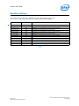
Acronyms and Terminology
The table below lists the acronyms and terminology used throughout this document.
Table 1.
Acronyms and Terminology (Sheet 1 of 4)
Term
ADD Card
Description
AGP Digital Display. An adapter card that can be inserted into the PCIe
x16 port of Intel chipset family-based systems. ADD cards allow
configurations for TV-out, LVDS, and TMDS output (i.e., televisions,
digital displays, and flat panel displays).
AIM
Add In Module.
API
Application Programming Interface.
BDA
BIOS Data Area. A storage area that contains information about the
current state of a display, including mode number, number of columns,
cursor position, etc.
BIOS
Basic Input/Output System. The Intel® Embedded Media and Graphics
Driver interacts with two BIOS systems: system BIOS and Video BIOS
(VBIOS). VBIOS is a component of the system BIOS.
BLDK
Boot Loader Development Kit.
CED
Configuration EDitor. Graphical pre-installation utility allows easy creation
of consolidated driver installation packages for Windows* operating
systems, and VBIOS across numerous platforms and display
combinations.
Clone Display Configuration
A type of display configuration that drives two display devices, each
displaying the same content, but can have different resolutions and
(independent) timings. Compare Twin Display Configuration and DIH
Display Configuration.
Contrast Ratio
Contrast ratio is the measure of the difference between light and dark on
a display. If the contrast is increased, the difference between light and
dark is increased. So something white will be very bright and something
black will be very dark. Brightness and Contrast Controls differ in function
between CRTs and LCDs.
COPP
Certified Output Protection Protocol* is a Microsoft-defined API to provide
application with information about what output protection options are
available on a system.
D3D
Microsoft Direct3D*. A3D graphics API as a component of DirectX*
technology.
DC
Display Configuration.
DDCT
Intel® Dynamic Display Configuration Technology.
DirectDraw*
A component of the DirectX* Graphics API in Microsoft Windows OS.
Intel® Embedded Media and Graphics Driver
User Guide
10
April 2013
Document Number: 472133-012
Introduction—Intel® EMGD
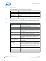
Table 1.
Acronyms and Terminology (Sheet 2 of 4)
Term
Description
DIH Display Configuration
Dual Independent Head. A type of display configuration that supports two
displays with different content on each display device. The Intel®
Embedded Media and Graphics Driver supports Extended mode for
Microsoft Windows systems.
DTD
Detailed Timing Descriptor. A set of timing values used for EDID-less
devices.
DVI
Digital Video Interface.
DVO
Digital Video Output.
EBDA
Extended BIOS Data Area. An interface that allows the system BIOS and
Option ROMs to request access to additional memory.
EDID
Extended Display Identification Data. A VESA standard that allows the
display device to send identification and capabilities information to the
Intel® Embedded Media and Graphics Driver. Intel® EMGD reads all EDID
data, including resolution and timing data, from the display, thus
negating the need for configuring DTD data for the device.
EDID-less
A display that does not have the capability to send identification and
timing information to the driver and requires DTD information to be
defined in the driver.
eIA
Embedded Intel® Architecture.
EVR
Enhanced Video Renderer
Extended Clone Mode
A feature that allows you to have different sized displays in Clone mode.
Framebuffer
A region of physical memory used to store and render graphics to a
display.
GDI
Graphics Device Interface. A low-level API used with Microsoft Windows
operating systems.
GMA
Intel Graphics Media Accelerator. Refers to both the graphic hardware in
Intel chipsets as well as the desktop/mobile driver. The GMA driver is not
intended for use in embedded applications.
GMS
Graphics Mode Select (stolen memory).
HAL
Hardware Abstraction Layer. An API that allows access to the Intel®
chipsets.
HDCP
High-bandwidth Digital-Content Protection. A specification that uses the
DVI interface. HDCP encrypts the transmission of digital content between
the video source (transmitter) and the digital display (receiver).
HDMI
High-Definition Multimedia Interface, an uncompressed, all-digital, audio/
video interface.
iDCT
Inverse Discrete Cosine Transform (hardware feature).
INF file
A standard Microsoft Windows text file, referred to as an information file,
used by Microsoft Windows OS to provide information to the driver. The
default .inf file for the Intel® Embedded Media and Graphics Driver is
igdlh32.inf. You can create customized parameters using the CED
utility.
LPCM
Linear Pulse Code Modulation. A method of encoding audio information
digitally. The term also refers collectively to formats using this method of
encoding.
LVDS
Low Voltage Differential Signaling. Used with flat panel displays, such as a
laptop computer display.
NTSC
National Television Standards Committee. An analog TV standard used
primarily in North and Central America, Japan, the Philippines, South
Korea, and Taiwan. Its resolutions are based on 525-line systems.
Compare PAL.
Option ROM (OROM)
Code that is integrated with the system BIOS and resides on a flash chip
on the motherboard. The Intel Embedded Video BIOS is an example of an
option ROM.
April 2013
Document Number: 472133-012
Intel® Embedded Media and Graphics Driver
User Guide
11
Intel® EMGD—Introduction
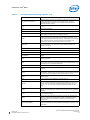
Table 1.
Acronyms and Terminology (Sheet 3 of 4)
Term
Description
OS
Operating System.
PAL
Phase Alternating Lines. An analog TV standard used in Europe, South
America, Africa, and Australia. Its resolutions are based on 625-line
systems. Compare NTSC.
PCF
Parameters Configuration File.
PCI
Peripheral Component Interface.
Port Driver
A driver used with the sDVO interfaces of the System Controller Hub
(SCH).
POST
Power On Self Test.
PWM
Pulse Width Modulation.
Saturation
Monitors and scanners are based on the “additive” color system using
RGB, starting with black and then adding Red, Green, and Blue to achieve
color. Saturation is the colorfulness of an area judged in proportion to its
brightness. Full saturation of RGB gives the perception of white, and
images are created that radiate varying amounts of RGB, or varying
saturation of RGB.
SCART
French Acronym - Syndicat des Constructeurs d'Appareils
Radiorecepterus et Televiseurs. A video interface possessing up to four
analog signals (Red/Green/Blue/Composite PAL). S-Video (Luma/
Chroma) is possible over the SCART interface as well.
SCH
System Controller Hub.
SCS
Software Compliance Statement.
sDVO
Serial Digital Video Output.
Single Display Configuration
A type of display configuration that supports one and only one display
device.
SSC
Spread Spectrum Clock.
Stolen Memory
A region of physical memory (RAM) set aside by the system BIOS for
input and output operations. The amount of stolen memory is
configurable. Stolen memory is not accessible to the operating system or
applications.
System BIOS
The standard BIOS used for basic input and output operations on PCs.
TMDS
Transitioned Minimized Differential Signaling. Used with DVI displays,
such as plasma TVs.
TOM
Top Of Memory.
TSR
Terminate and Stay Resident. A program that is loaded and executes in
RAM, but when it terminates, the program stays resident in memory and
can be executed again immediately without being reloaded into memory.
Twin Display Configuration
A type of display configuration that supports two display devices each of
which has the same content, resolution, and timings. Compare Clone
Display Configuration. Note: Twin configuration is not supported on
US15W series chipsets.
VBIOS
Video Basic Input Output System. A component of system BIOS that
drives graphics input and output.
VESA
Video Electronics Standards Organization.
VGA
Video Graphics Array. A graphics display standard developed by IBM* that
uses analog signals rather than digital signals.
Intel® Embedded Media and Graphics Driver
User Guide
12
April 2013
Document Number: 472133-012
Introduction—Intel® EMGD
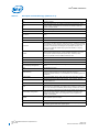
Table 1.
Acronyms and Terminology (Sheet 4 of 4)
Term
1.6
Description
VLD
Variable Length Decode.
WHQL
Windows* Hardware Quality Labs. WHQL is a testing organization
responsible for certifying the quality of Windows drivers and hardware
that runs on Windows operating systems.
YUV
Informal, but imprecise reference to the video image format, Y'CbCr. The
Y' component is luma, a nonlinear video quality derived from RGB data
denoted without color. The chroma components, Cb and Cr, correspond
nonlinearly with U and V as differences between the blue and luma, and
between the red and luma, respectively.
Downloading Intel® EMGD and Video BIOS
Download Intel® EMGD and the Video BIOS (VBIOS) from one of the following
locations:
• From the Intel Embedded Design Center (http://www.intel.com/p/en_US/
embedded/hwsw/software/emgd#download) only, where the following is available:
Intel Embedded Media and Graphics Driver Configuration Editor (CED) release
— includes the Intel® EMGD drivers for VBIOS and all Windows* operating
systems, plus an embedded help system
— currently runs only on Windows operating systems.
• From the QuAD system: Intel Premier Support (QuAD) (https://premier.intel.com)
• From the new IPS system: https://businessportal.intel.com. You will be redirected
to: https://welcome.intel.com/login.aspx where you will need to log in.
Click on the Product Support tab.
Note: DO NOT use the Design & Technology tab, which takes you to the old IPS
system.
Note:
The latest version of embedded Video BIOS is recommended for use with each of the
graphics drivers in most cases. Click the following link to see the FAQ page for details
on the differences of these versions.
http://edc.intel.com/Software/Downloads/EMGD/#faqs
After you have downloaded, installed, and run CED, you can configure and customize
the drivers and VBIOS following the procedures in this document. After they have been
configured, you can integrate the VBIOS with the system BIOS ROM and install Intel®
EMGD on your operating system.
§§
April 2013
Document Number: 472133-012
Intel® Embedded Media and Graphics Driver
User Guide
13
Intel® EMGD—Architectural Overview
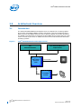
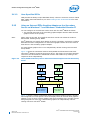
2.0
Architectural Overview
2.1
Introduction
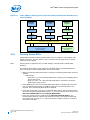
The Intel® Embedded Media and Graphics Driver is composed of a runtime graphics
driver and a Video BIOS (VBIOS) firmware component. (See the illustrations below.)
Both the driver and VBIOS control the SCH to perform display and render operations.
The VBIOS is predominantly leveraged by System BIOS during system boot but is also
used at runtime by the driver to handle full-screen text mode on Microsoft Windows*
operating systems.
Figure 1.
Intel® Embedded Media and Graphics Driver
Intel®
Embedded Firmware
Intel® Atom™
processor
E6xx
Intel® Embedded Media and
Graphics Driver
Internal LVDS
sDVO Port
Transmitter
Encode
Intel® Embedded Media and Graphics Driver
User Guide
14
April 2013
Document Number: 472133-012
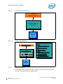
Architectural Overview—Intel® EMGD
Figure 2.
Graphics Driver Architecture
Application
Graphics Interface API
Intel® Embedded Media and
Graphics Driver
Intel® Atom™
processor
E6xx
Figure 3.
Firmware Architecture
System BIOS/Application
Dispatch
Entry point for applications (INT10)
VGA
Standard VGA mode setting
VESA
Standard VESA support
®
Intel Embedded Firmware
Dispatch
VESA
VGA
FPI
Intel API
Intel API
Intel-specific features, including flat
panel detect, backlight, etc.
Firmware Port Interface (FPI)
CRT and sDVO interface support
Intel®
Embedded
Processor
2.1.1
Display Options
The following section describes the types of displays and configurations supported by
the Intel® Embedded Media and Graphics Driver.
April 2013
Document Number: 472133-012
Intel® Embedded Media and Graphics Driver
User Guide
15
Intel® EMGD—Architectural Overview
2.1.1.1
Types of Displays
The table below lists the types of displays supported by the Intel® Embedded Media
and Graphics Driver.
Table 2.
Types of Displays Supported
Display
Description
CRT
Analog CRT, supported with an external transmitter via an sDVO port.
TMDS and LVDS compliant flat panels are supported with the use of an external
transmitter via an sDVO port. Integrated LVDS flat panels are also natively supported on
the Intel® System Controller Hub US15W/US15WP/WPT chipset and Intel® Atom™
Processor E6xx.
Flat Panel
TV
2.1.1.2
TV-out is supported via an external encoder sDVO port.
Display Configuration
Intel® EMGD supports driving two displays simultaneously. Several configurations are
supported, dependent on operating system and chipset. The various display
configurations are described in the table below.
Table 3.
Display Configuration Definitions
Display Configuration Mode
Single
Clone†
Extended†
Description
Normal desktop configuration, single monitor
Two displays, same content, different resolutions, independent timings
Two displays, continuous content (available in Windows only)
† Supported display depends on driver and hardware availability. See the RelNotes.txt for more information.
The table below summarizes which display configurations are supported by Intel
chipsets.
Table 4.
Supported Display Configurations
Operating System
Chipset
Windows* 7 and Windows Embedded Standard* 7
Intel® Atom™ Processor E6xx
Single, Clone, Extended
Note:
Intel®
US15W/US15WP/WPT
Depends on driver and hardware availability.
Single, Clone, Extended
Intel® EMGD supports Clone mode through custom APIs. In contrast, Microsoft
Windows natively supports Extended and DIH.
2.2
Features
The following sections describe major features Intel® EMGD supports.
2.2.1
Chipsets Supported
The table below lists Intel® EMGD-supported chipsets.
Intel® Embedded Media and Graphics Driver
User Guide
16
April 2013
Document Number: 472133-012
Architectural Overview—Intel® EMGD
Table 5.
Chipsets Supported by the Intel® EMGD
Intel® EMGD
VBIOS Support
Intel® EMGD
Support
Intel® Atom™ Processor E6xx
Yes
Yes
Intel® System Controller Hub US15W/US15WP/WPT chipset
Yes
Yes
Chipset
All supported chipsets provide for SINGLE LVDS output. In addition, digital monitors,
CRTs and TVs are supported through the US15W/US15WP/WPT and MCH/Intel® Atom™
Processor E6xx sDVO interfaces, depending on hardware availability.
2.2.2
OS and API Support
The Intel® Embedded Media and Graphics Driver and Video BIOS support the following
operating systems and APIs.
• Microsoft Windows* 7 Professional
• Microsoft Windows* 7 Ultimate
• Microsoft Windows* Embedded Standard 7
• DirectX* 9.0Ex
• DirectX* Video Acceleration (DXVA) 2.0
• Intel® Media SDK 2.0
• OpenGL 2.0
2.2.3
EDID-Less Configuration
EDID-less support is the ability to run a display panel that does not have display timing
information within the panel. Therefore, the user has to provide the display timing
information to the graphics drivers during configuration using CED. See “Creating a
New Customized DTD” on page 20.
This document describes only the necessary edits to the configuration files that are
required to implement the graphics driver and VBIOS, and not specific settings for
EDID-less panel configuration. Please refer to the manufacturer’s specifications for the
DTD settings to use for your EDID-less panels.
2.2.3.1
EDID-Less Panel Type Detection
The Intel® Embedded Media and Graphics Driver supports EDID-less displays that do
not export timing modes. This is accomplished by allowing configuration of a Detailed
Timing Descriptor (DTD), and associating that DTD with a specific display port.
2.2.4
Rotation
Rotation is the ability to rotate the display for the Intel® Embedded Media and Graphics
Driver. Rotation support includes 0°, 90°, 180°, 270°. Rotation is supported only on
the following chipsets:
• Intel® Atom™ Processor E6xx
• Intel® System Controller Hub US15W/US15WP/WPT chipset
Note:
Rotation is not supported with the VBIOS.
§§
April 2013
Document Number: 472133-012
Intel® Embedded Media and Graphics Driver
User Guide
17
Intel® EMGD—Platform Configuration Using CED
3.0
Platform Configuration Using CED
The Intel® EMGD Configuration Editor (CED) is a Windows-based Graphical User
Interface (GUI) that allows you to create configurations, package the configurations,
and create installations that can be loaded directly on a specific OS or Video BIOS
platform. Configurations are associated with a specific chipset and can be created for
any one of the following supported chipsets:
• Intel® Atom™ Processor E6xx
• Intel® System Controller Hub US15W/US15WP/WPT chipset
CED runs on both Windows* 7 32-bit and 64-bit environments.
The CED GUI is designed for ease of use and configuration of the Intel® EMGD. Each
configuration page has online help available and each data field is validated. If you
enter an incorrect value, CED displays an error message at the top of the page and
displays the valid range of values for the field. You cannot finish a configuration until all
fields contain valid values.
The following sections show how to create a configuration for any of the supported
chipsets, operating systems, and the Intel® EMGD Video BIOS.
• “Starting CED” on page 20
• “Creating a New Customized DTD” on page 20
• “Creating a New Configuration” on page 24
• “Creating a New Package” on page 36
• “Generating an Installation” on page 38
3.1
Before You Begin
To configure the Intel® EMGD software using CED, you will need some information on
the panel you are using. This information is usually found in the product specifications.
In some cases the terminology used in CED may not match the labels used in your
panel’s product specification. Refer to Table 7, “Timing Specification Example Values”
on page 23 for hints on which specs correspond to CED Detailed Timings Descriptor
(DTD) fields. After you obtain the correct specification values, you may need to derive
other values for the DTD fields.
Intel® Embedded Media and Graphics Driver
User Guide
18
April 2013
Document Number: 472133-012
Platform Configuration Using CED—Intel® EMGD
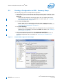
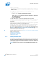
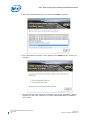
3.2
Creating a Configuration in CED – Summary Steps
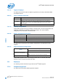
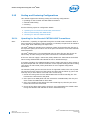
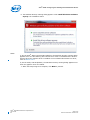
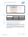
The following steps present a sample CED configuration.
1. (Optional) If you have custom panels and timings you may want to create your own
DTD; otherwise you can use the standard DTDs provided by CED. If needed, select
New DTD.
— Choose the DTD Type that most closely aligns with your display parameters,
enter parameters, and then click Finish. Or, to create a DTD, see “Creating a
New Customized DTD” on page 20.
2. Select New Configuration.
— Enter a name for the configuration, select the mode, chipset, ports, port
drivers, DTDs, etc., for the configuration and then click Finish. For details, see
“Creating a New Configuration” on page 24.
3. Select New Package.
— Enter a name for the package, select the configurations for your package, the
platforms for the installation, and then click Finish. For details, see “Creating a
New Package” on page 36.
4. Select the created package and then select Generate Installation.
The generated files are placed in the installation folder. The zip files contain the
generated configuration files. For details, see “Generating an Installation” on
page 38.
Figure 4.
Sample CED Configuration Start Page
April 2013
Document Number: 472133-012
Intel® Embedded Media and Graphics Driver
User Guide
19
Intel® EMGD—Platform Configuration Using CED
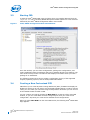
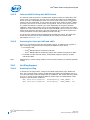
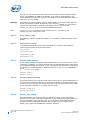
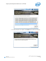
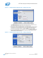
3.3
Starting CED
To start the Intel® EMGD CED, open the folder where you installed CED and click the
emgd-ced.exe icon. The Intel® EMGD CED splash window appears for a few moments
followed by the Intel® EMGD Configuration Editor main window.
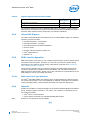
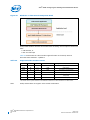
Figure 5.
Intel® EMGD Configuration Editor Main Window
From this window, you can create configurations, package the configurations, and
create installations from the packages that can be installed directly on a platform. The
main window also provides a Console tab that displays information when you build a
package or an installation.
The following sections show how to create a configuration for any of the supported
chipsets, operating systems, and the Intel® EMGD Video BIOS.
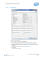
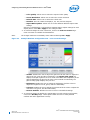
3.4
Creating a New Customized DTD
CED allows you to create Dynamic Timings Definitions (DTD) for EDID-less displays or
displays for which you do not want to use the display's EDID settings. In either of those
cases, you can create your own DTD using the steps below. Otherwise you can use one
of the standard DTDs included in CED.
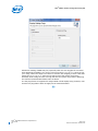
You can create a new DTD by clicking the New DTD link at the top of the main CED
window, or you can create DTDs for each configured port when you create a new
configuration. Any DTDs you create will be available for all configurations.
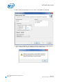
When you select New DTD from the main CED window, the following Intel® EMGD DTD
Page appears.
Intel® Embedded Media and Graphics Driver
User Guide
20
April 2013
Document Number: 472133-012
Platform Configuration Using CED—Intel® EMGD
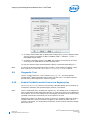
Figure 6.
EMGD DTD Page
To create a custom DTD setting:
1. From the CED main screen, select New DTD.
2. Enter a name for the DTD in the text box provided, for example, test_LVDS.
3. Using the data sheet from the panel being used, enter the DTD timings in the
appropriate fields. Refer to Table 6, “Intel® EMGD DTD Setting Options” for field
descriptions.
The screen will be similar to the example shown in Figure 6.
4. Click Finish.
The custom DTD is complete.
April 2013
Document Number: 472133-012
Intel® Embedded Media and Graphics Driver
User Guide
21
Intel® EMGD—Platform Configuration Using CED
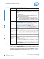
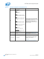
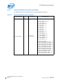
Table 6.
Intel® EMGD DTD Setting Options (Sheet 1 of 2)
DTD Parameter
Description
Enter DTD File Name
Enter a name for this customized DTD. This is a required field and the
name must be between 1 and 50 characters and may contain spaces and
underscores.
DTD Type
Select the DTD Type that most closely aligns with your display
parameters. Options are:
• Intel® EMGD Parameters:
The Intel® EMGD Parameters are the same as the current PCF/CED
DTD parameters.
• VESA Parameters:
The VESA Parameters allow the user to create a DTD from a VESA
monitor timing standard.
• Hardware Parameters:
The Hardware Parameters are the parameters that are used by
Intel® EMGD.
• Simple Parameters:
The Simple Parameters (CVT Standard) is a process for computing
standard timing specifications. The method for developing Reduced
Blanking timings is not included.
• Mode Lines:
The Mode Lines are a video timing spec used by X.Org. The X.Org
timing setting for Mode Lines is “name” I A B C D E F G H. For
example: “640x480@8bpp” 25.175 640 672 728 816 480 489 501
526.
• EDID Block:
The EDID Block is the detailed timing section (18 bytes) of the basic
128-byte EDID data structure. The detailed timing section starts at
36h of the 128-byte EDID data structure. Enter the EDID block 1
byte at a time. Example:
a0 0f 20 00 31 58 1c 20 d2 1a 14 00 f6 b8 00 00 00 18
Pixel Clock
DTD Settings Flags
Pixel clock value in KHz. Range 0-1000000.
This section allows you to set flags for Interlace, Vertical Sync Polarity,
Horizontal Sync Polarity, and Blank Sync Polarity. Each field in this
section is described below.
Interlaced Display:
• Check for Interlaced
• Cleared for Non-interlaced
Vertical Sync Polarity:
• Active Low (Default)
• Active High
Horizontal Sync Polarity:
• Active Low (Default)
• Active High
Blank Sync Polarity:
• Active Low (Default)
• Active High
Note:
These flags are Intel® EMGD-specific and do not correspond to
VESA 3.0 flags.
Horizontal Sync Offset (Front
Porch) in pixels
Specifies the amount of time after a line of the active video ends and the
horizontal sync pulse starts (Horizontal Front Porch). Range 0-8191 [13
bits].
Horizontal Sync Pulse Width (Sync
Time) in pixels
Width of the Horizontal Sync Pulse (Sync Time) which synchronizes the
display and returns the beam to the left side of the display. Range 08191 [13 bits].
Horizontal Blank Width (Blank
Time) in pixels
This parameter indicates the amount of time it takes to move the beam
from the right side of the display to the left side of the display (Blank
Time). During this time, the beam is shut off, or blanked. Range 0-32767
[15 bits].
Intel® Embedded Media and Graphics Driver
User Guide
22
April 2013
Document Number: 472133-012
Platform Configuration Using CED—Intel® EMGD
Table 6.
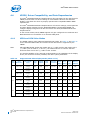
3.4.1
Intel® EMGD DTD Setting Options (Sheet 2 of 2)
DTD Parameter
Description
Horizontal Active (Width) in pixels
Number of pixels displayed on a horizontal line (Width). Range 1-32767
[15 bits].
Horizontal Sync Start in pixels
This parameter specifies the start of the horizontal active time.
Range 0-40957.
Horizontal Sync End in pixels
This parameter specifies the end of the horizontal active time.
Range 0-49148.
Horizontal Blank Start in pixels
This parameter specifies the start of one line of the video and margin
period. Range 0-32766.
Horizontal Blank End in pixels
This parameter specifies the end of one line of the video and margin
period. Range 0-65533.
Refresh in Hz
Also known as the Vertical Refresh, the rate the full display updates.
Standard refresh rates are 50Hz, 60Hz, 75Hz, and 85Hz.
Vertical Sync Offset (Front Porch)
in lines
Specifies the amount of time after last active line of video ends and
vertical sync pulse starts (Vertical Front Porch). Range 0-63 [6 bits].
Vertical Sync Pulse Width (Sync
Time) in lines
Specifies the Width of the Vertical Sync Pulse which synchronizes the
display on the vertical axis and returns the beam to the top, left side of
the display. Range 0-63 [6 bits].
Vertical Blank Width (Blank Time)
in lines
The amount of time for the complete vertical blanking operation to
complete. It indicates the time it takes to move the beam from the
bottom right to the top, left side of the display (Blank Time). During this
time, the beam is shut off, or blanked. Range 0-4095 [12 bits].
Vertical Active (Height) in lines
The number of active lines displayed (Height). Range 1-4095 [12 bits].
Vertical Sync Start in lines
This parameter specifies the start of the vertical sync. Range 0-4157.
Vertical Sync End in lines
This parameter specifies the end of the vertical sync. Range 0-4220.
Vertical Blank Start in lines
This parameter specifies the start of display vertical blanking including
margin period. Range 0-4094.
Vertical Blank End in lines
This parameter specifies the end of vertical blanking. Range 0-8189.
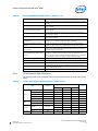
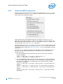
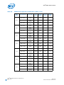
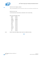
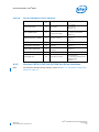
DTD Example Specifications
The following table shows example product specifications that can be used in the timing
fields.
Table 7.
Timing Specification Example Values (Sheet 1 of 2)
Standard value
Item
Frequency
Period
Clock
Hi-time
Low-time
Data
H sync.
H display
April 2013
Document Number: 472133-012
Symbol
Unit
Min.
Typ.
Max.
1/ts
29.91
33.231
36.55
ts
27.36
30.06
33.43
ns
tsh
7
–
–
ns
ns
MHz
tsl
7
–
–
DUTY ratio
th/tl
35
50
65
ns
Setup time
tds
7
–
–
ns
Hold time
tdh
4
–
–
ns
24.51
31.75
32.05
us
880
1056
1088
clk
Period
tlpl, tlpd
Pulse width
tlw
3
128
200
clk
Term
thd
800
800
800
clk
Intel® Embedded Media and Graphics Driver
User Guide
23
Intel® EMGD—Platform Configuration Using CED
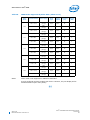
Table 7.
Timing Specification Example Values (Sheet 2 of 2)
Standard value
Item
Symbol
Unit
Min.
Enable
V sync.
V display
3.5
Max.
Setup time
tdrs
7
–
–
ns
Hold time
tdrh
4
–
–
ns
Period
tfpf, tfpd
520
525
680
Line
Pulse width
tfw
1
2
3
Line
Term
tvd
480
480
480
Line
Start
tfd
10
33
40
Line
H sync. ~ enable
Phase
difference
Typ.
tdrds
50
216
260
clk
H sync. ~ clock
tls
7
–
–
ns
H sync. ~V sync.
tn
7
–
–
ns
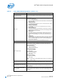
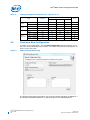
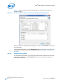
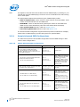
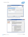
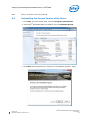
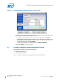
Creating a New Configuration
To create a new configuration, click the New Configuration selection located on the
top of the Intel® EMGD CED main window. The Chipset Configuration Page appears, as
shown on the next page.
Figure 7.
Chipset Configuration Page
The Chipset Configuration Page allows you to specify settings that apply to Windows* 7
and Windows Embedded Standard* 7 operating systems and VBIOS platforms.
Intel® Embedded Media and Graphics Driver
User Guide
24
April 2013
Document Number: 472133-012
Platform Configuration Using CED—Intel® EMGD
The table below describes each setting on the Chipset Configuration page.
Table 8.
Chipset Configuration Page Settings
Setting
Configuration File Name
Platform Chipset
Description
Provide a name for the configuration you are creating. This name is
required and is used when you create packages. The name can consist
of any alphanumeric characters and any special characters and must be
between 1 and 50 characters. You must enter a configuration before you
can enter any other information on this page.
Select the target chipset for this configuration from the drop-down list.
Display Configuration Mode
Select the type of display configuration from the drop-down list. You can
select any one of the following display configurations:
• Single — Single display configuration.
• Clone — Two displays where both displays have the same content
but can have different resolutions and timings.
• DIH — Dual Independent Head. This is a configuration where both
displays can have different resolutions, different refresh rates, and
different content.
Note:
Port Devices (Available Ports, Port
Order)
The Port Devices section lists the ports available based on the chipset
selected.
The Available Ports box lists the ports available to the chipset. You can
move these port devices to the Port Order box to determine the search
order for detecting attached displays. To move a port device to the Port
Order box, either double-click the port device or click the port device to
highlight it, and then click the right arrow button to move it from the
Available Ports to the Port Order box.
The Port Order section allows you to determine the search order for
detecting attached displays for the Display Detection feature. When
Display Detection is enabled, the Port Order determines which display is
primary and which display is secondary.
Note:
3.5.1
On Microsoft Windows* DIH configurations, the display DOES
NOT automatically come up in extended display mode. You
must go into the Display properties on the Control Panel and
manually set the display to DIH mode.
When you move one or more ports to the Port Order box, you
can configure each port by clicking Next. For each port listed in
the Port Order box, you can click Next to configure each port.
See “Configuring Ports” on page 27 for information on
configuring ports.
Setting Color Correction
Color Correction is available for framebuffers, and is accessed under the New
Configuration link at the top of the main CED window. For framebuffer color
correction, user-assigned values must be between 0.6 to 6. By default, gamma is 1.0
(no correction).
3.5.1.1
Framebuffer Color Correction Attributes
Framebuffer Color Correction Attributes lets you adjust the main color attributes. This
feature allows you to color-correct for red, green, and blue, and enables you to adjust
brightness and contrast.
Table 9.
Framebuffer Color Correction Values (applies to R, G, B color)
Gamma:
0.6 to 6.0 (default value is 1)
Brightness:
-127 to 127 (default value is 0)
Contrast:
-127 to 127 (default value is 0)
April 2013
Document Number: 472133-012
Intel® Embedded Media and Graphics Driver
User Guide
25
Intel® EMGD—Platform Configuration Using CED
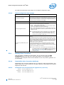
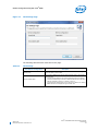
To assign framebuffer color correction, click the Framebuffer Color Correction
Attributes button on the port configuration page (LVDS or sDVO). The Framebuffer
Color Correction Page appears, as shown in Figure 8.
Figure 8.
Framebuffer Color Correction Page
Add your desired values to the correction fields and then click Finish.
Intel® Embedded Media and Graphics Driver
User Guide
26
April 2013
Document Number: 472133-012
Platform Configuration Using CED—Intel® EMGD
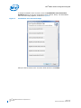
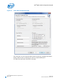
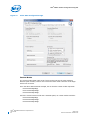
3.5.2
Configuring Ports
You can configure each port listed in the Port Order box of the Chipset Configuration
Page by clicking Next. When you do, a port Configuration Page appears similar to the
one shown following.
Figure 9.
Port Configuration Page
The Port Configuration Page allows you to specify whether to use EDID timings or
customized DTD timings for the display connected to this specific port. From this page,
you can also specify Attribute Settings, I2C Settings, and Flat Panel Settings and create
a new DTD that can be used with any configuration.
The table below describes each field on this page.
April 2013
Document Number: 472133-012
Intel® Embedded Media and Graphics Driver
User Guide
27
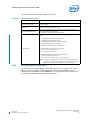
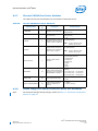
Intel® EMGD—Platform Configuration Using CED
Table 10.
Port Configuration Settings (Sheet 1 of 2)
Port Configuration
Field
Description
Readable Port Name
Enter a name for the port. This is a required field and the name must be between 1 and
12 characters and may contain spaces.
Port Rotation
This list allows you select a rotation for the display connected to this port. You can
choose between 0, 90, 180, and 270 degrees. The default is 0.
EDID Options
This section allows you to set EDID options for the display. The Intel® EMGD supports
three different types of EDID display modes:
• Built-in display modes: These modes are hard-coded in the Intel® EMGD. These
modes can be filtered based on the EDID block.
• EDID Block: These are Detailed Timing Descriptors read from an EDID display. An
EDID display can contain DTD as well as other information about the display.
• User-specified DTDs.
See “Advanced EDID Configuration” on page 47 for more information on EDID
configuration flags.
If you want to use the display's EDID information if it is available, click the Use EDID
Display if Available check box.
If the display attached to this port contains EDID information, you can choose one or
more of the following options from the If EDID Device section to determine which set
of timings to use for the display connected to the port:
• Use driver built in standard timings — If this box is checked, the standard timings
built into the Intel® EMGD are used.
• Use EDID block — If this box is checked, the EDID block is used.
• Use user-defined DTDs — If this box is checked, a user-defined DTD is used. You
can select which DTD to use by checking the appropriate box in the Custom
Display Timings Descriptors (DTDs) section. If no DTDs are defined, you can click
New DTD and create a custom DTD. For information on creating custom DTD,
refer to Table 6 on page 22.
• Use Panning Mode DTDs — If this box is checked, a panning mode DTD is used.
You can select which panning modes to use by checking the appropriate box in the
Panning Mode DTDs section.
If you select both Use driver built-in standard timings and Use EDID block, the
Intel® EMGD uses its built-in display timings and the timings provided by the display.
If the display attached to this port does not contain EDID information, you can choose
one or both of the following options from the If Not EDID Device section:
• Use driver built-in standard timings — If this box is checked, the standard timings
are used. See “Advanced EDID Configuration” on page 47 for more information on
built-in standard timings.
• Use user-defined DTDs — If this box is checked, a user defined DTD is used. You
can select which DTD to use by checking the appropriate box in the Custom
Display Timings Descriptors (DTDs) section. If no DTDs are defined, you can click
New DTD and create a custom DTD. For information on creating custom DTD,
refer to Table 6 on page 22.
• Use Panning Mode DTDs — If this box is checked, a panning mode DTD is used.
You can select which panning modes to use by checking the appropriate box in the
Panning Mode DTDs section.
See “Sample Advanced EDID Configurations” on page 48 for example configurations.
Intel® Embedded Media and Graphics Driver
User Guide
28
April 2013
Document Number: 472133-012
Platform Configuration Using CED—Intel® EMGD
Table 10.
Port Configuration Settings (Sheet 2 of 2)
Port Configuration
Field
DisplayID Option
Description
This option provides flexibility to enable/disable display rotation configuration based on
DisplayID file.
To enable display rotation configuration based on DisplayID file, please ensure you do
following:
• Check the Determine rotation from device orientation option box
• Leave the Port Rotation options under CED LVDS or sDVO configuration page
unchecked or set to 0.
• Check the Use EDID display if available option box and under “If EDID Device
(edid_avail)” check the EDID block option for the graphics driver to get the
rotation information from the DisplayID file.
Note:
Encoder
Configuration
If you set the Port Rotation option in CED to a non-zero value, then the
graphics will use your setting regardless of the DisplayID option enabled. If
you would like to change the DisplayID after driver installation, ensure you
delete the DisplayConfigProcessed key through regedit before you change the
DisplayID data. Reboot the system after DisplayID data is changed.
This section lets you to specify the type of encoder connected to an sDVO port and
encoder Attributes, I2C settings, and Flat Panel settings for the port.
The Select sDVO Device drop-down list contains the list of all supported sDVO
devices. Select the device that will be connected to this port.
To change the device's attributes, click the Attribute Settings button. Refer to
“Changing Port Attribute Settings” for information on device attributes.
To change the device's I2C settings, click the I2C Settings button. See “Changing I2C
Settings” on page 30 for information on I2C settings.
To change the device's flat panel settings, click the Flat Panel Settings button. See
“Changing Flat Panel Settings” on page 32 for information for changing flat panel
settings.
This option appears only for the sDVO Configuration Page. It allows you to disable TV
Out for CH7317 and CH7022.
Disable TV (Only for
Windows)
Note:
TV Out is enabled by default by the driver unless it is set to Disabled in CED.
For CH7317, the user must choose Disable TV to disable TV detection in the
driver because the CH7317 chip does not have TV Out and it incorrectly
reports TV encoders to the driver.
3.5.2.1
Framebuffer Color
Correction
Attributes
Framebuffer Color Correction Attributes allow you to adjust the main Frame Buffer
color attributes. See “Framebuffer Color Correction Attributes” on page 25.
Custom Display
Timing Descriptors
(DTDs)
The Custom Display Timing Descriptors (DTDs) drop-down list contains the list of
user-defined timing descriptors. Select the DTD for the display that will be connected
to this port.
• New DTD — To create a custom descriptor, see Section 3.4, “Creating a New
Customized DTD” on page 20
• Native DTD Flag — The Native DTD list lets you choose whether to use a display's
built-in timings.
Panning Mode DTDs
The panning mode allows you to set a resolution that is larger than the native
resolution of the display panel.
The Panning Mode DTDs drop-down list contains the list of standard panning mode
DTDs. Select the DTD for the display that will be connected to this port.
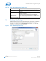
Changing Port Attribute Settings
When you click the Attributes Settings button from the Encoder Configuration section
of the Port Configuration Page, CED displays a page of attributes for the selected
encoder device. The actual page that appears depends upon the encoder device
selected and only the attributes that apply to the selected encoder appear. For a full
description of all attributes for all supported encoders, refer to Appendix A, “Port Driver
Attributes”.
April 2013
Document Number: 472133-012
Intel® Embedded Media and Graphics Driver
User Guide
29
Intel® EMGD—Platform Configuration Using CED
Figure 10 shows a sample Attributes Settings Page for the Chrontel CH7022 and
CH7308 encoders.
Figure 10.
Attribute Settings Page for the Chrontel CH7022/CH7308 Encoders
When the Attributes Settings Page first appears, it shows the Use Default box checked
for all attributes.
To change a default value, clear the Use Default check box and enter a new value. For
a description of all attributes for all supported encoders, see Appendix A, “Port Driver
Attributes”.
3.5.2.2
Changing I2C Settings
The I2C Settings Page allows you to specify the I/O interface connections to devices on
an sDVO port. When you click I2C Settings from the Port Configuration Page, the
following screen appears.
Intel® Embedded Media and Graphics Driver
User Guide
30
April 2013
Document Number: 472133-012
Platform Configuration Using CED—Intel® EMGD
Figure 11.
I2C Settings Page
The following table describes each field on this page.
Table 11.
I2C Settings
I2C/DDC Bus Configuration
Description
Speed (KHz)
Speed of I2C bus for the device and for the EDID device. The range for
these two fields is 10-400 KHz.
Device Address Byte
Enter a device address byte for the device that this port is connected to
in these boxes:
• The I2C device address is for reading and writing device registers.
The device address byte must be in 8-bit format with the 7-bit slave
address assigned to its bits 7:1 and bit 0 set to 0.
• The DDC Device Address Byte is the I2C device address for reading
EDID data from the display through the DDC bus.
April 2013
Document Number: 472133-012
Intel® Embedded Media and Graphics Driver
User Guide
31
Intel® EMGD—Platform Configuration Using CED
3.5.2.3
Changing Flat Panel Settings
The Panel Settings Page allows you to specify settings for a flat panel display connected
to this sDVO port. When you click Flat Panel Settings from the Port Configuration
Page, the following screen appears.
Figure 12.
Panel Settings Page for sDVO on CH7308
Intel® Embedded Media and Graphics Driver
User Guide
32
April 2013
Document Number: 472133-012
Platform Configuration Using CED—Intel® EMGD
The table below describes each section of this page.
Table 12.
Panel Settings Options
Flat Panel Settings
Description
Single/Dual Channel (Applies
only to Chrontel 7308)
Select the type of panel, Single or Dual channel. This setting is not supported
for internal LVDS.
Bit Depth
This list lets you select a color depth for the panel. You can choose either 18
or 24 bit color depth. The default is 18.
Flat Panel Backlight Options
This section provides options for controlling the backlight of the flat panel
display and specifying timing delays.
The backlight Control Method is always enabled.
This section lets you specify timing delays for the backlight signals as
follows:
•
•
•
•
•
Timing Delays
T1-VDD active and sDVO clock/data active.
T2-DVO active and backlight enable.
T3-Backlight disable and DVO clock/data inactive.
T4-DVO clock/data active and inactive.
T5-Minimum from VDD inactive and active.
For Internal LVDS, the timing range is as follows:
• T1 to T4: 0-409, increment by 1.
• T5: 1-1600, increment by 50.
For CH7308 and CH7036, the timing range is as follows:
• T1 to T4: 0-4095, increment by 1.
• T5: 1-<Max 4 byte integer value>, increment by 50.
Note:
3.5.3
Timers are very specific to the panel you are using. If they are set
incorrectly the display can be damaged or ruined. Please refer to the
datasheet for your display to determine the correct settings.
Configuring the Video BIOS
The final page of the Intel® EMGD Configuration allows you to configure your video
BIOS (if you are creating a configuration that includes the Video BIOS). You can
configure the Video BIOS by clicking Next after you configure each port. When you do,
the following Video BIOS Configuration Page appears.
April 2013
Document Number: 472133-012
Intel® Embedded Media and Graphics Driver
User Guide
33
Intel® EMGD—Platform Configuration Using CED
Figure 13.
Video BIOS Configuration Page
From this page, you can customize POST (Power On Self Test) messages and default
display modes as well as matching port devices to System BIOS ports.
The table below describes each field on this page.
Intel® Embedded Media and Graphics Driver
User Guide
34
April 2013
Document Number: 472133-012
Platform Configuration Using CED—Intel® EMGD
Table 13.
Video BIOS Settings Options (Sheet 1 of 2)
Video BIOS Settings
Description
Primary Display Mode
This section allows you to specify a standard or a customized display mode
for the primary display. You can select a standard mode from any of the
standard modes listed in the drop-down list. If you want to use a customized
mode for the primary display, check the Custom check box and enter the
mode number in the box. For a complete list of customized VGA and VESA
modes, refer to Table 19, “Supported VGA Video Display Modes” on page 62
and Table 20, “VESA Modes Supported by Video BIOS” on page 64.
Secondary Display Mode
This section allows you to specify a standard or a customized display mode
for the secondary display. You can select a standard mode from any of the
standard modes listed in the drop-down list. If you want to use a customized
mode for the secondary display, check the Custom check box and enter the
mode number in the box. For a complete list of customized VGA and VESA
modes, refer to Table 19, “Supported VGA Video Display Modes” on page 62
and Table 20, “VESA Modes Supported by Video BIOS” on page 64.
5F Functions
These settings allow you to enable or disable the five System BIOS 15h
interrupt hooks. Please see Appendix C, “Intel® 5F Extended Interface
Functions” for more information on 5F functions.
All five functions are enabled by default.
The Common to Port section lets you match port devices with common
System BIOS ports. This allows the Video BIOS to retrieve information about
the port from the System BIOS. It allows you to associate standard display
names used in most system BIOSs to specific ports that are recognized by
Intel® EMGD (for example, LVDS, sDVO). The VBIOS makes this association
when the VBIOS calls the System BIOS Intel® 5F interrupt functions.
This setting consists of six numbers, where each number is associated with
one of the System BIOS displays:
1
2
3
4
5
6
Common to Port
:
:
:
:
:
:
CRT - Standard analog CRT
TV1 - TV Output 1
EFP1 - DVI Flat Panel 1
LFP - Local Flat Panel (Internal LVDS display)
TV2 - TV Output 2
EFP2 - DVI Flat Panel 2
The values above are an example of the typical displays and corresponding
order used by a system BIOS. However, this may vary depending on how
your system BIOS has implemented the displays and the Intel 5F interrupt
functions.
The value in each position in the setting should be the associated port
device. Using the typical settings above, if you want to associate CRT in the
system BIOS with the internal CRT (port 1) and LFP in the system BIOS with
internal LVDS (port 4) in the VBIOS, select CRT from the VBIOS Port Devices
list and click the left arrow button next to the CRT row in the Matches
column, and then select LFP from the VBIOS Port Devices list and click the
left arrow button next to the LFP row in the Matches column.
Notes: This feature must be compatible with the System BIOS. If the
System BIOS does not properly implement the Intel 5F functions,
then using the Common to Port feature could cause unpredictable
results with the displays. If you are unsure, leave the Matches
column blank for all ports to disable this feature.
The Display Detect field on the Chipset Configuration page must be
set to Enable in order for the Common to Port values to be used.
Enable POST messages to
display
To enable Power On Self Test (POST) messages to display during the power
on sequence, check this box. If left unchecked (i.e., cleared), the POST
messages do not display.
OEM String
Enter a string of up to 100 characters. This string appears on the display
when the Video BIOS starts up. The default is a blank string.
April 2013
Document Number: 472133-012
Intel® Embedded Media and Graphics Driver
User Guide
35
Intel® EMGD—Platform Configuration Using CED
Table 13.
Video BIOS Settings Options (Sheet 2 of 2)
Video BIOS Settings
3.6
Description
OEM Vendor Name
Enter a string of up to 80 characters that identifies the OEM Vendor. This
string appears on the display when the Video BIOS starts up. The default is a
blank string.
OEM Product Name
Enter a string of up to 80 characters that identifies the OEM Product
Revision. This string appears on the display when the Video BIOS starts up.
The default is a blank string.
OEM Product Revision
Enter a string of up to 80 characters that identifies the OEM Product
Revision. This string appears on the display when the Video BIOS starts up.
The default is a blank string.
Number of Seconds to Display
Enter the number of seconds to display the above information. The default is
1.
Creating a New Package
A package consists of one or more configurations and is used to create an installation
that works for multiple operating systems and chipset platforms and displays.
To create a new package, click the New Package link at the top of the main CED
window. The Intel® EMGD Package Page appears.
Figure 14.
Intel® EMGD Package Editor Page
Intel® Embedded Media and Graphics Driver
User Guide
36
April 2013
Document Number: 472133-012
Platform Configuration Using CED—Intel® EMGD
The table below describes each field on this page.
Table 14.
Intel® EMGD Package Editor Setting Options
Package Option
Package File Name
Description
Enter a name for the package. This is a required field and the name
must be between 1 and 50 characters and may contain spaces.
This block shows the configurations that are available to be packaged.
Each package consists of one or more configurations, each of which is
associated with a specific chipset.
To select a configuration, click the check box next to the configuration
name. You can select all available configurations by clicking Select All
located below the Configurations block and clear all configurations by
clicking Clear All.
Configurations
The Configuration Name column shows the name of each configuration
and the Chipset column shows the chipset associated with each
configuration.
In the Config ID column, you must enter a configuration ID for each
configuration. The configuration ID must be a number between 1 and
15. By default, the Package Editor automatically assigns the next
available configuration ID when you select a configuration. You can
change the default configuration ID by clicking in the edit box and
entering a different value.
Default Configuration
The Default Configuration list box allows you to select a default
configuration from the configurations you selected in the Configurations
block.
For single configurations the default is the one selected in the previous
option. For multiple configurations, the default is the first one selected in
the Configurations list. To have no default configuration, select None.
See also Section 5.2.1, “Universal INF Configuration” on page 66.
Target OS
This block allows you to select one or more operating systems and Video
BIOS for the package. For each target you select, CED produces a
configuration file for the selected OS or Video BIOS platform.
If you are not creating a VBIOS package, click Finish. When you click Finish, CED
creates a package that can be used for generating an installation.
3.6.1
Generating a VBIOS Package
If you are creating a package for a VBIOS installation, click Next. CED displays the
VBIOS Generation page.
April 2013
Document Number: 472133-012
Intel® Embedded Media and Graphics Driver
User Guide
37
Intel® EMGD—Platform Configuration Using CED
Figure 15.
VBIOS Generation Page
To generate a VBIOS, click the Generate VBIOS check box and select the
configurations to include. After selecting the chipset and the configurations, click
Finish. CED generates a package that includes both the OROM and the TSR for the
chipsets and the configurations you selected.
3.7
Generating an Installation
After you have created a package, you can generate an installation for the package by
following this procedure.
1. Select a package from the Package folder located on the left pane of the CED main
window.
2. Click Generate Installation. While the installation is building, CED displays a
progress bar. When the installation is complete, CED places the output in the
Installation folder on the left pane of the CED window.
For each OS and VBIOS platform specified in the package, CED generates a folder in
the ...\workspace\installation folder under the current folder. For example, if
you select a package that contains configurations for all supported operating systems
and the VBIOS, CED generates the following folders:
...\workspace\installation\<package name_installation>\IEMGD_HEAD_WINDOWS7
...\workspace\installation\<package name_installation>\IEMGD_HEAD_VBIOS
These folders contain all the subfolders required for the installation onto the target
systems. To complete the installations on the target systems, refer to “Configuring and
Installing Microsoft Windows Drivers” on page 66.
Intel® Embedded Media and Graphics Driver
User Guide
38
April 2013
Document Number: 472133-012
Platform Configuration Using CED—Intel® EMGD
Note:
With the E6xx platform configuration, CED will generate a 127K vBIOS ROM image; for
the US15W platform configuration, CED will generate a 64K vBIOS ROM image.
3.8
Configuring the System BIOS for Use with the Intel® EMGD
Some aspects of configuring the Intel® Embedded Media and Graphics Driver are
common across the Video BIOS (VBIOS) and the drivers for the supported operating
systems. The following sections provide an overview for configuring both the VBIOS
and Intel® EMGD and describe in detail the common components and tools. This
section also describes how to configure the system BIOS for the supported systems.
3.9
System BIOS Settings
Before installing Intel® EMGD, you must first configure the system BIOS. The following
sections describe the required settings. These descriptions are based on AMIBIOS8*
from American Megatrends, Inc., which is the recommended system BIOS to use with
Intel® EMGD. Settings may vary if a different system BIOS is used.
3.9.1
GMCH PCIe Device Enabling
The PCIe Device Enabling feature on the Graphics and Memory Controller Hub (GMCH)
should be set as specified in the table below.
Table 15.
GMCH Device 2, Function 1 BIOS Setting
Chipset
OS
Intel® Atom™ Processor E6xx, Intel® US15W/US15WP/WPT
Microsoft Windows* 7 and
Microsoft Windows*
Embedded Standard 7
3.9.2
Disabled
Graphics Mode Select (GMS)
The System BIOS typically allows a portion of physical memory to be dedicated to
firmware and graphics driver use. This dedicated memory is known as stolen memory
since it is not available to the operating system. The size of this memory is selectable
and chipset-specific. Stolen memory is typically used by the firmware and graphics
driver to locate the framebuffer, but can also be used as scratch and surface memory.
Because it is programmatically set aside during boot by the System BIOS, access to it
is direct and does not require OS memory allocation services. Firmware is fully
responsible for stolen memory management.
Graphics Mode Select (GMS), or stolen memory, can be set to any of the sizes listed in
the table below. Smaller sizes limit the framebuffer size during firmware boot. Larger
sizes marginally increase surface allocation performance for the graphics driver.
Table 16.
GMS Settings
Chipset
®
GMS Settings
Intel US15W/US15WP/WPT
64 MB, 128 MB, 256 MB
Intel® Atom™ Processor E6xx
64 MB, 128 MB, 256 MB
April 2013
Document Number: 472133-012
Intel® Embedded Media and Graphics Driver
User Guide
39
Intel® EMGD—Platform Configuration Using CED
3.9.3
AGP (Accelerated Graphics Port) Aperture Size
The AGP Aperture size controls the total amount of graphics memory that can be
mapped in the AGP Aperture. This value can be set from 64 MB up to 256 MB,
depending on the chipset. Refer to specific chipset details for information on the valid
range.
3.10
VBIOS and Driver Configuration
The Intel Embedded Graphics Suite allows user configuration of both the VBIOS and
graphics driver as well as programming of Detailed Timing Descriptors (DTDs) for
EDID-less panels for both the VBIOS and graphics driver. This is accomplished using
CED, which offers several ways to input DTDs, each associated with a potential target
panel and display mode for the system. CED generates DTD and configuration settings
used by the Intel® EMGD VBIOS, Linux, and/or Windows drivers.
The following example is for a system setup with just an internal LVDS and sample
timing parameters for illustration purposes only. You can use this example to set up
DTD timings that are specific to your non-standard panels and then activate the panels
using a custom mode.
To create a configuration and configure the LVDS options:
1. Create a custom DTD as described in Section 3.4, “Creating a New Customized
DTD” on page 20.
2. From the CED main screen, select New Configuration.
3. Enter a name for the configuration in the text box provided, for example,
LVDS_test.
4. Select the platform chipset.
5. In the list of available ports, select LVDS and then click Next.
6. On the LVDS Configuration Page, clear the checkbox for Use EDID Display if
available, which disables all the selections under If EDID Device (edid_avail).
The screen will be similar to the example below.
7. Select the checkbox for Use user-defined DTDs.
8. In the Encoder Configuration section, select Internal LVDS.
9. In the Custom Display Timing Descriptors (DTDs) list, select the DTD you created in
Section 3.4, “Creating a New Customized DTD” on page 20 for example,
test_LVDS.
Intel® Embedded Media and Graphics Driver
User Guide
40
April 2013
Document Number: 472133-012
Platform Configuration Using CED—Intel® EMGD
Figure 16.
LVDS Configuration Page
10. Click Next.
To set the custom mode:
1. From the Intel® EMGD CED screen (similar to the example below), in the Primary
Display Mode section, clear the Use Default checkbox.
2. In the Primary Non-standard Modes section, select the checkbox for Custom.
3. In the Primary Non-standard Modes section, enter 0x120 in the Default Mode
Settings text box. (See a description of the custom modes.)
April 2013
Document Number: 472133-012
Intel® Embedded Media and Graphics Driver
User Guide
41
Intel® EMGD—Platform Configuration Using CED
Figure 17.
Video BIOS Configuration Page
Custom Modes
The custom modes begin with 0x120 (0x121 and 0x122 are the same modes in
different pixel formats). If there was a second custom mode entered it would begin
with 0x123 to 0x125.
From the above DTD 200x200 example, this is what the custom modes represent:
0x120 200x200@8bpp
0x121 200x200@16bpp
0x122 200x200@32bpp
And if the second custom mode was a 400x400 panel, its custom modes would be:
0x123 400x400@8bpp
0x124 400x400@16bpp
0x125 400x400@32bpp
Intel® Embedded Media and Graphics Driver
User Guide
42
April 2013
Document Number: 472133-012
Platform Configuration Using CED—Intel® EMGD
3.11
Configuration Options
The table below describes available Intel® EMGD settings. The gray rows are block
headings and the non-gray rows that follow each heading are settings within the block.
Some of these block headings are contained within prior block headings.
Table 17.
Parameter Configuration Format (Sheet 1 of 4)
Name
Range/Value
Description
ConfigID
Integer (1-15)
Optional keyword used to specify which
configuration is used. The config ID specified
here must match one of the configuration IDs
defined with CED. If this keyword is omitted, all
configurations specified in the config file are
used.
Note that this keyword is not required for Linux
OS and VBIOS configurations.
Config
Integer (1-15)
More than one configuration is valid.
Comment
A quoted string used to identify the origin of the
.bin or .inf file.
Name
A quoted string used to identify the
configuration name.
Name is a required field for VBIOS
configuration.
General
Settings that are generic to the configuration.
DisplayConfig
Used to configure initial state of attached
displays.
1 – Single. A single display.
2 – Clone. Primary and secondary displays
enabled and configured with separate timing
pipes. This allows different timings to be applied
to each display. Resolutions can be different on
both displays.
8 – Extended. Configures separate pipes to
allow primary and secondary displays to have
different resolutions and display different
content. Upon first boot after the driver
installation, this option will enable only the
primary display, as the extended modes must
be enabled in the operating system (i.e.,
Extended Desktop in the Display Properties
sheet within Microsoft Windows).
1 – Single
2 – Clone
8 – Extended
Default: 8
PortOrder
PortOrder must be specified as a
quoted string containing five digits.
The valid values are:
2 - sDVO B port
4 - Integrated LVDS port (mobile
chipsets only)
Default: 0 for all keys
This block contains settings for the Video BIOS.
Note that you only need to specify the
parameters you are actually using. You do not
need to specify all the parameters in this block.
If you omit any parameters, the vbios uses the
default values.
vbios
port
April 2013
Document Number: 472133-012
Search order for detecting attached displays for
the Display Detection feature. When Display
Detection is enabled, the PortOrder determines
which display is primary and which display is
secondary.
The port search order can be specified to ensure
the port device (sDVO device) is found, based
on the system integrator’s routing choices.
Default ordering is chosen by specifying zeros in
the PortOrder keys.
Default ordering is chipset specific; see
Table 29, “Default Search Order” on page 104.
2 -sDVO B port
4 - Integrated LVDS port (mobile
chipsets only)
Used to define port specific settings.
Intel® Embedded Media and Graphics Driver
User Guide
43
Intel® EMGD—Platform Configuration Using CED
Table 17.
Parameter Configuration Format (Sheet 2 of 4)
Name
rotation
Range/Value
Degrees
• 0
• 90
• 180
• 270
Description
Rotation of the display.
Default: 0 degrees
EnableHotPlug
1 - Enable Hot Plug
0 - Disable Hot Plug
Default: 1 Enable
This parameter is used to enable or disable the
hot plug feature for an sDVO port.
HotPlugDelay
Default 550ms
Unit in ms
Range 100-1000ms
This parameter is used to enable or disable the
hot plug feature for the sDVO port.
edid
0 – Do not read EDID from panel/CRT
1 – Attempt to extract EDID timing
data from panel/CRT
If VBIOS/driver reads EDID from panel/CRT.
Range [16 bits]
Valid values (specified in hex):
bit 0=0: Do not use built-in standard
timings.
=1: Use driver built-in standard
timings.
edid_avail
edid_not_avail
bit 1=0: Do not use EDID block.
=1: Use EDID block and filter
modes.
(Bit 1 not applicable to
edid_not_avail.)
bit 2=0: Do not use user-defined
DTDs.
=1: Use user-defined DTDs.
bits 3-15: Reserved for future use.
DIDRotation
Range:
0 - Disable. Do not use rotation
setting based on DisplayIDfile.
1 - Enable. Use rotation setting based
on the DisplayIDfile for display port
configuration
Intel® Embedded Media and Graphics Driver
User Guide
44
These two parameters are used to control the
available timings for any display. edid_avail is
used when EDID values are read from the
display. If an attempt to read EDID from the
display fails or the edid parameter is set to 0,
then the driver uses the edid_not_avail flags.
The value for both parameters must be specified
as a decimal or hex value, e.g., “3” or “0x3”
Defaults:
edid_avail: “3” sets Bit 0 = 1, Bit 1 = 1, Bit 2 =0
(Use driver built-in standard timings and EDID
block and filter modes.)
edid_not_avail: “1” sets Bit 0 = 1, Bit 1 = 0, Bit
2 = 0. (Use driver-built-in standard timings.)
Please see Section 3.12, “Advanced EDID
Configuration” on page 47 for detailed
information.
This option provides flexibility to enable/disable
display rotation configuration based on
DisplayID file.
Default: disabled
To enable display rotation configuration based
on the DisplayID file, please ensure you
configure the following parameters:
• DIDRotation =1
• rotation =0
• edid =1
• edid_avail = 2 or 3 or 6 or 7
Note:
If you set the Port Rotation option in
CED to a non-zero value, then the
graphics will use your setting
regardless of the DisplayID option
enabled. If you would like to change the
DisplayID after driver installation,
ensure you delete the
DisplayConfigProcessed key through
regedit before you change the
DisplayID data. Reboot the system
after DisplayID data is changed.
April 2013
Document Number: 472133-012
Platform Configuration Using CED—Intel® EMGD
Table 17.
Parameter Configuration Format (Sheet 3 of 4)
Name
Range/Value
dvo
Description
sDVO device information.
i2cpin
<0-6>
The GPIO pin pair used on the I2C bus to read
and write to sDVO device registers.
ddcpin
<0-6>
The GPIO pin pair used as DDC bus to read
panel EDID data.
i2cdab
<0x00-0xff>
I2C device address for reading and writing
device registers.
The device address should be in 8-bit format
with the 7-bit slave address assigned to its bits
7:1 and bit 0 set to 0.
ddcdab
<0x00-0xff>
I2C device address for reading EDID data from
display through the DDC bus.
i2cspeed
[10-400]. Units in KHz
Speed of I2C bus for sDVO device.
ddcspeed
[10-400]. Units in KHz
Speed of I2C bus for EDID device.
fpinfo
Panel-specific information.
bkltt1
(T1) Time delay between VDD active, and sDVO
clock/data active. Zero indicates no delay
required.
bkltt2
bkltt3
Range [0 -0xfff].
Units of 1ms => the limit specified in
your hardware specifications. For
example, the maximum for the
CH7307 is 409 ms.
(T2) Time delay between sDVO clock/data
active and backlight enable.
(T3) Time delay between backlight disable and
sDVO clock/data inactive.
bkltt4
(T4) Time delay between sDVO clock/data
inactive and VDD inactive.
bkltt5
(T5) Minimum delay between VDD inactive, and
active.
dtd
Denotes a Detailed Timing Descriptor (DTD)
block. Settings in this section, except for the
flags parameter, correspond to the Detailed
Timing Block described in the VESA standard
“Extended Display Identification Data Standard”,
Version 3, November 13, 1997.
p_clock
Range [0-0x7fffffff]
Pixel clock value in KHz.
h_active
Range 0-4096 [12 bits]
Horizontal Active.
v_active
Range 0-4096 [12 bits]
Vertical Active.
h_sync
Range 0-1024 [10 bits]
Horizontal Sync Offset.
v_sync
Range 0-64 [6 bits]
Vertical Sync Offset.
h_syncp
Range 0-1024 [10 bits]
Horizontal Sync Pulse Offset.
v_syncp
Range 0-64 [6 bits]
Vertical Sync Pulse Width.
h_blank
Range 0-4096 [12 bits]
Horizontal Blanking.
v_blank
Range 0-4096 [12 bits]
Vertical Blanking.
h_border
Range 0-256 [8 bits]
Horizontal Border. Currently not supported.
v_border
Range 0-256 [8 bits]
Vertical Border. Currently not supported.
h_size
Range 0-4096 [12 bits]
Horizontal Size. Currently not supported.
v_size
Range0-4096 [12 bits]
Vertical size. Currently not supported.
April 2013
Document Number: 472133-012
Intel® Embedded Media and Graphics Driver
User Guide
45
Intel® EMGD—Platform Configuration Using CED
Table 17.
Parameter Configuration Format (Sheet 4 of 4)
Name
Range/Value
Description
Range [32 bits]
Valid values:
bit 31
0 - Non-interlaced
1 - Interlaced
bit 27
0 - vertical sync polarity active low
1 - vertical sync polarity active high
bit 26
0 - horizontal sync polarity active low
1 - horizontal sync polarity active
high
flags
bit 25
0 - blank sync polarity active high
1 - blank sync polarity active low
Interlace, Horizontal polarity, Vertical polarity,
Sync Configuration, etc. Note that these flags
are Intel® EMGD specific and do not correspond
to VESA 3.0 flags. For example, to set
Interlaced with Horizontal Sync Polarity high
(bits 31 and 26), then the flags value =
0x84000000. (Binary = 10000100 00000000
00000000 00000000)
bit 20
0 - disable display panning (default)
1 - enable display panning
bit 17
0 - Normal DTD
1 - Panel/display Native DTD
All other bits
Do not use any other bits; all other
bits must be set to 0.
attr
0-0xFFFF
Attribute values that are specific to the sDVO
device for the port. See Appendix A, “Port Driver
Attributes” for specific attribute IDs and
associated values.
id = <value>.
id <Attribute ID>
0 -4294967296
Both the Attribute ID and its value should be
specified in decimal. For example, to set
brightness to 50, you specify
id 0 = 50
See Appendix A, “Port Driver Attributes”
Intel® Embedded Media and Graphics Driver
User Guide
46
April 2013
Document Number: 472133-012
Platform Configuration Using CED—Intel® EMGD
3.12
Advanced EDID Configuration
Shown in the following EDID Options example, the If EDID Device (edid_avail) and
If Not EDID Device (edid_not_avail) options in CED are found on the CRT, sDVO,
LVDS, and TV Out configuration pages.
These options control the available timings for any display. Use the edid_avail
parameter when EDID information is read from the display. If the driver cannot read
EDID information from the display or if the edid parameter is set to “0” (disable), then
use the settings of the edid_not_avail parameter.
The default behavior of edid_avail is to use the driver’s built-in standard timings and
EDID block and filter modes. The default for edid_not_avail uses the driver’s builtin standard timings. Please see Table 17 in Section 3.11 for more information on these
parameters.
The driver will use 1024x768, 800x600, and 640x480 as built-in standard timings if
there was no user-defined DTDs specified in the INF and if any of the following
conditions are met:
1. The edid configuration flags specified only to use the driver built-in standard
timings. Examples:
“edid” = 0, “edid_avail” = (any value), “edid_not_avail” = 0
“edid” = 1, “edid_avail” = 0, “edid_not_avail” = 0
2. The edid configuration flags resulted in a NULL timing list (i.e., user requested to
use user-defined DTDS, but there were no user-defined DTDs specified in the INF
file or the user requested to use EDID-DTDs, but the panel contains no EDID
information). Examples:
“edid” = 0, “edid_avail” = (any value), “edid_not_avail” = 5 (no user-DTDs were
defined)
“edid” = 1, “edid_avail” = 0, “edid_not_avail” = 4 (no user-DTDs were defined)
“edid” = 1, “edid_avail” = 4, “edid_not_avail” = (any value) (no user-DTDs were
defined)
“edid” = 0, “edid_avail” = (any value), “edid_not_avail” = 2 (panel has no EDID
information)
April 2013
Document Number: 472133-012
Intel® Embedded Media and Graphics Driver
User Guide
47
Intel® EMGD—Platform Configuration Using CED
Note:
This applies to internal and external LVDS as well as SDVO displays (excluding TV). For
internal and external LVDS displays, the driver will use 1024x768 as the native timing
for the LVDS panel.
The Intel® EMGD supports these different types of EDID display modes:
• Built-in display modes. These modes are hard-coded in the Intel® EMGD. These
modes can be filtered based on the EDID block.
• EDID-DTDs: These are Detailed Timing Descriptors read from the EDID block.
EDID can have these DTDs along with other information about the display.
• User-specified DTDs defined in CED. See Section 3.12.2.
• User Panning Mode DTDs defined in CED. See Section 3.14.
The Advanced EDID Configuration supports different possible combinations of display
modes when an EDID display is present along with user-specified DTDs.
3.12.1
Sample Advanced EDID Configurations
The table below presents various EDID configurations and the EDID settings in CED
used for those configurations.
Table 18.
Sample Advanced EDID Configurations
Configurations
1. Use all built-in modes and any EDID-DTDs
when the display has EDID information.
2. Use filtered built-in modes (1024x768,
800x600, 640x480) when the display does not
contain EDID information.
CED Settings
Description
edid = 1
edid_avail = 3
edid_not_avail = 1
Default values.
1. Use all built-in modes and EDID-DTDs when
the display has EDID information.
2. Use only user-DTDs otherwise.
edid = 1
edid_avail = 3
edid_not_avail = 4
This configuration allows the
Intel® EMGD to use its built-in
display modes and the modes
provided by the display.
If the Intel® EMGD is unable
to read EDID information from
the display, then the Intel®
EMGD uses the user-DTDs
defined in CED.
1. Use only user-DTDs regardless of connected
display. (Typically used for a custom panel that
only supports user-defined DTDs.)
edid = 0
edid_avail = (any value)
edid_not_avail = 4
Only user-DTDs defined in CED
are used.
edid = 1
edid_avail = 2
edid_not_avail = 4
This configuration uses the
EDID-DTDs when detecting an
EDID display and EDID
information comes from the
display.
If the driver detects a nonEDID display, then the Intel®
EMGD uses user-DTDs defined
in CED.
edid = 1
edid_avail = 6
edid_not_avail = 4
This configuration uses both
EDID-DTDs and user-DTDs
when the Intel® EMGD detects
an EDID display.
If the driver detects a nonEDID display, then the Intel®
EMGD uses user-DTDs defined
in CED.
1. Use EDID-DTDs for an EDID display.
2. Use user-DTDs for a non-EDID display.
1. Use only EDID-DTDs and user-DTDs for an
EDID display.
2. Use user-DTDs only for a non-EDID display.
Intel® Embedded Media and Graphics Driver
User Guide
48
April 2013
Document Number: 472133-012
Platform Configuration Using CED—Intel® EMGD
3.12.2
User-Specified DTDs
CED provides the ability to input DTD data directly. There are numerous sources of DTD
data: VESA, panel manufacturers, etc. See Creating a New Customized DTD for more
information.
3.13
Using an External PCIe Graphics Adapter as the Secondary
Device on Windows* 7 and Windows* Embedded Standard 7
You can configure an external PCIe card to work with the Intel® EMGD as follows:
• The external PCIe card as the secondary graphics adapter and the GMCH internal
graphics device as the primary.
Note:
When using an ATI card, first install the ATI driver and do not reboot the machine.
Reboot after installing Intel® EMGD.
Intel® EMGD lets you specify which display is primary, secondary, and tertiary. It allows
Extended and Clone configurations on the internal graphics device when the external
PCIe device is the secondary graphics adapter.
An external PCIe graphics driver runs independently without sharing resources with
Intel® EMGD.
Figure 18 shows the interaction between Intel® EMGD and the External VGA driver
when Intel® EMGD is booted as the primary driver. The drivers do not share hardware
resources. The OS decides the framebuffer content and handles it by drawing to the
respective driver independently.
Figure 18.
Intel® EMGD as Primary Driver and External PCIe Graphics Card as Secondary
Driver
Primary
Secondary
Configured Port
Ext VGA Port
Intel® EMGD
Driver
VGA Driver
OS-Handles Graphics Driver Requests
Intel® EMGD
Resource Allocation
(Stolen Memory)
Ext VGA
Resource Allocation
(Ext Video)
Figure 19 shows a sample configuration where the internal graphics device is primary
and configured to use two ports to drive two displays while an external PCIe graphics
adapter is used to drive a tertiary display. Note that regardless of the number of ports
being assigned to a driver, the external PCIe graphics run independently without
sharing resources with Intel® EMGD.
April 2013
Document Number: 472133-012
Intel® Embedded Media and Graphics Driver
User Guide
49
Intel® EMGD—Platform Configuration Using CED
Figure 19.
Intel® EMGD as Primary Driver with Two Displays and External PCIe Driving a
Tertiary Display
Primary
Display
Secondary
Display
Tertiary
Display
Primary Port
Secondary Port
Ext VGA Port
Intel® EMGD
Driver
IEGD Driver
VGA Driver
OS-Handles Graphics Driver Requests
Intel® EMGD
Resource Allocation
(Stolen Memory)
3.14
Ext VGA
Resource Allocation
(Ext Video)
Panning Modes DTDs
Intel® EMGD introduces Panning Mode DTDs control to support a small display with
higher resolutions. Use this option to set a resolution that is larger than the native
resolution of the display.
Note:
Panning Mode is supported only on LVDS displays (internal LVDS or sDVO LVDS
displays).
The Panning Mode DTDs control applies to both EDID Device and Not EDID Device.
Here is the logic of Panning Mode DTDs control on the CED:
• When Use Panning Mode DTDs option is checked, the Panning Mode DTDs control is
enabled.
— CED settings:
• edid_avail |= 8 if Use Panning Mode DTDs is checked in the If EDID Device
group control and
• edid_not_avail |= 8 if Use Panning Mode DTDs is checked in the If Not
EDID Device group control
• If Not EDID Device, the Use Panning Mode DTDs option is enabled only when the
Use user-defined DTDs option is enabled. If the Use user-defined DTDs is not
checked, then Use Panning Mode DTDs is disabled.
• If the DTD is selected in the Use user-defined DTDs control, the same DTD cannot
be used in the Panning Mode DTDs control, i.e., the DTD cannot be the same for the
Use user defined DTDs and the Panning Mode DTDs
• If the user selects a native mode from the Use User-Defined DTD list, the
Panning Mode DTDs list contains the selected non-native user-defined DTDs that
are greater than or equal to, i.e., either the width or height is greater or equal to
the native mode DTD.
Intel® Embedded Media and Graphics Driver
User Guide
50
April 2013
Document Number: 472133-012
Platform Configuration Using CED—Intel® EMGD
3.15
Scaling and Centering Configurations
This release supports the following scaling and centering configurations:
• Upscaling for the Chrontel CH7308 LVDS Transmitters
• Internal LVDS Scaling
• Centering
See the following topics for configuration details:
• “Upscaling for the Chrontel CH7308 LVDS Transmitters”
• “Internal LVDS Scaling with EDID Panels”
• “Centering for Internal LVDS and sDVO”
3.15.1
Upscaling for the Chrontel CH7308 LVDS Transmitters
Note:
In Windows 7, upscaling is supported through the CH7308 LVDS transmitter. When a
lower resolution (compared to native resolution) is selected, the panel will be scaled to
fit the panel while maintaining the aspect ratio.
The Intel® EMGD can upscale lower-resolution modes (those smaller than the size of
the respective panel) to the native size of the panel connected to a Chrontel CH7308*
LVDS transmitter.
The Intel® EMGD uses a user-supplied DTD with the native flag set (also known as
native DTD) as native timing for the panel connected to a CH7308 transmitter.
If the user does not supply a native DTD, Intel® EMGD uses 1024x768 as the default
native timing and 800x600 and 640x480 as built-in standard timings.
To support upscaling, the LVDS transmitters require setting the pipe to native timing of
the panel despite the user-selected resolution. It also requires finding the native timing
(also known as native DTD) of the panel based on user-supplied configuration
information.
The CH7308 (sDVO) port drivers limit the list of supported modes to the size of panel.
The port drivers also mark one of the timings as native DTD as follows (it goes to the
next step only if native DTD is not found in the current step).
1. It finds the timing with the user-defined DTD with the native DTD flag set. This
becomes the native DTD for the panel.
2. If the panel is an EDID panel and user selected to use EDID DTDs, then the port
driver marks the EDID DTD as native DTD.
3. If the user supplies a DTD without the native DTD flag set, then the port driver
marks this one as the native DTD.
4. If none of the above steps works, the driver uses 1024x768 as the default native
timing and 800x600 and 640x480 as built-in standard timings.
April 2013
Document Number: 472133-012
Intel® Embedded Media and Graphics Driver
User Guide
51
Intel® EMGD—Platform Configuration Using CED
3.15.2
Internal LVDS Scaling with EDID Panels
The Internal LVDS connected to an EDID Panel supports scaling of modes other than
native mode. To support this, the port driver exports information to the EDID parser
that it can scale. The EDID parser does not remove other modes (that is, non-native
modes) from the mode table. It only marks the native mode. When the Intel® EMGD
queries the port driver on which modes are supported, the port driver then removes
any modes that cannot be scaled (up or down depending on the port's hardware
capability). When mode-setting occurs, the second display in Clone mode can indeed
support non-native modes even though the panel had EDID. This occurs only if a native
mode can be found the port driver can scale. Otherwise, the port driver ignores the
scaling information and the Intel® EMGD proceeds normally.
The driver also supports Internal LVDS Scaling on EDID-less panels. The steps that
enable this are the same as those described for the scaling of Chrontel LVDS
transmitters in Section 3.15.1.
3.15.3
Centering for Internal LVDS and sDVO
There is no user-defined centering and upscaling (Panel_Fit attribute 18) support in
CED. Centering is supported only through Intel® EMGD as shown below.
• For internal LVDS,
— Intel® EMGD supports centering on US15W
— Intel® EMGD supports maintaining aspect ratio instead of centering on E6xx
• For SDVO (includes external LVDS), Intel® EMGD supports centering on both
US15W and E6xx.
Note:
SDVO display is center scaling capable, but this needs the Panel_Fit attribute available
in CED.
3.16
Hot Plug Support
3.16.1
Enabling Hot Plug
To enable the hot plug feature, configure the sDVO configuration page “Enable Hot
Plug” and “Hot Plug Delay” options in CED before generating the installation driver or
you could manually include the parameters in the INF file. The “Enable Hot Plug” option
is set to “1” which means enabled by default; default value for HotPlugDelay is 550.
Example of the parameter in INF file:
HKR, ALL\1\Port\2\General , EnableHotPlug, %REG_DWORD%, 1
HKR, ALL\1\Port\2\General , HotPlugDelay , %REG_DWORD%, 550
Intel® Embedded Media and Graphics Driver
User Guide
52
April 2013
Document Number: 472133-012
Platform Configuration Using CED—Intel® EMGD
April 2013
Document Number: 472133-012
Intel® Embedded Media and Graphics Driver
User Guide
53
Intel® EMGD—Platform Configuration Using CED
Sometimes reading of EDID may fail, especially when the user wiggles the connector
while attaching the display. You can try to fine tune the HotPlugDelay timing to suit
your usage, within the range from 100ms to 1000ms with stepping of 10ms. Note that
setting the HotPlugDelay value too low may prevent the monitor from being
detected, while having the value too high will lock the system longer before detecting
the monitor. Recommended default value is 550ms.
The hot plug feature is supported for single sDVO or dual display setup; however, note
that the hot plug feature does not apply for the LVDS transmitter.
§§
Intel® Embedded Media and Graphics Driver
User Guide
54
April 2013
Document Number: 472133-012
Video Firmware—Intel® EMGD
4.0
Video Firmware
4.1
Overview
The Intel Embedded Video BIOS incorporates many of the features and capabilities of
the Intel® Embedded Media and Graphics Driver. The 1.18 version of the VBIOS
includes support for the following chipsets:
• Intel® Atom™ Processor E6xx
• Intel® System Controller Hub US15W/US15WP/WPT chipset
Enabling the SMSW instructions used when Intel® EMGD VBIOS sets up its caching
functions increases the boot speed during POST and system boot. Caching is vital for
the Intel® EMGD VBIOS and it uses SMSW by design. Changes to the Intel® Embedded
Media and Graphics Driver VBIOS cannot happen without affecting its performance.
4.2
System Requirements
The new Video BIOS can be built on a host Microsoft Windows* system and moved to
the target system. The host system must have a 32-bit Microsoft Windows operating
system installed with the capability to execute DOS commands from a command line
window.
The target system must contain one of the following Intel chipsets:
• Intel® Atom™ Processor E6xx
• Intel® System Controller Hub US15W/US15WP/WPT chipset
The target system must contain a minimum of 64 MB of RAM.
4.3
Configuring and Building the VBIOS with CED
The Intel® Embedded VBIOS is built with the Intel Configuration Editor (CED). The
VBIOS will use the configuration that you specify in CED. The VBIOS is selected to be
built when you specify the Video BIOS as a Target OS in your package configuration.
After specifying the Video BIOS, follow all CED prompts, and be sure to select
“Generate VBIOS” when available. The VBIOS will then be built when you select
“Generate Installation” in CED.
Before building your VBIOS, you must set up your DOS environment with the steps
below.
1. Download the Open Watcom* C/C++ compiler from http://www.openwatcom.com.
The User Build System for the VBIOS relies on the Open Watcom C/C++ compiler
to be able to build a 16-bit DOS binary required for the BIOS. The VBIOS has been
tested with version 1.7a of the Open Watcom compiler.
2. Install the Open Watcom* C/C++ compiler using the full or complete option. Do
not use the default installation option as it may cause errors when
creating the BIOS in CED.
April 2013
Document Number: 472133-012
Intel® Embedded Media and Graphics Driver
User Guide
55
Intel® EMGD—Video Firmware
3. Set up directory paths.
You must set up the PATH environment variable in DOS to be able to execute the
Watcom compiler. If Watcom was installed with its default path, CED will by default
be able to use it.
When you generate a VBIOS, CED produces the following folders and files:
• Compiled_VBIOS folder
— iegdtsr.exe (Terminate and Stay Resident executable)
Note: iegdtsr.exe is available only for the US15W platform. Any description
about iegdtsr.exe in subsequence paragraphs and sections is applicable to
the US15W platform only.
— VGA.BIN (Option ROM)
•
IEMGD_HEAD_VBIOS.zip (this file is generated by the build system)
The iegdtsr.exe can be copied to any folder on the target machine. To run the TSR,
boot the target machine with DOS, and then run the iegdtsr.exe from the DOS
command line.
The VGA.bin file is the binary option ROM that can be merged with your system BIOS
per the instructions provided by your system BIOS vendor.
The IEMGD_HEAD_VBIOS.zip file contains default builds of the TSR executable and
Option ROM for the various chipsets. The filenames are iegdtsr-def.exe and
vga-def.bin and are located in the tsr or orom folder of the specific chipset folder
(see Figure 20). Refer to Appendix E, “Using the AMI* Video BIOS Utility” for
instructions on using the command line utility to merge the VBIOS ROM image with the
hardware platform system BIOS ROM image.
For further VBIOS build guidelines, see Section 4.3.3, “Building the VBIOS” on page 59.
See also the following topics:
• “Selecting the Build Folder”
• “Configuring the Video BIOS”
• “Building the VBIOS”
4.3.1
Selecting the Build Folder
The 1.18 version of the VBIOS contains specific folders used for creating a VBIOS that
is either an option ROM (OROM) that can be merged with the system BIOS, or an
executable Terminate and Stay Resident (TSR) program for debugging purposes. There
are also separate directories for the different chipsets that are supported. CED will build
both the TSR and OROM.
Figure 20 shows the directory structure for the Video BIOS libraries contained within
CED.
Intel® Embedded Media and Graphics Driver
User Guide
56
April 2013
Document Number: 472133-012
Video Firmware—Intel® EMGD
Figure 20.
Video BIOS Directory Structure
4.3.2
Configuring the Video BIOS
Use CED to configure the VBIOS. Display settings will be used the same way as for the
driver.
4.3.2.1
COMMON_TO_PORT
This setting allows you to associate standard display names used in most system BIOSs
to specific ports that are recognized by Intel® Embedded Media and Graphics Driver
(e.g., LVDS, sDVO-B). The VBIOS makes this association when the VBIOS calls the
System BIOS Intel® 5F interrupt functions.
This setting is a six digit number, where each digit is associated with one of the system
BIOS displays (from left to right):
1 : CRT - Standard analog CRT
2 : TV1 - TV Output 1
3 : EFP1 - DVI Flat Panel 1
4 : LFP - Local Flat Panel (Internal LVDS display)
5 : TV2 - TV Output 2
6 : EFP2 - DVI Flat Panel 2
The example values above show the typical displays and corresponding order used by a
system BIOS. However, this may vary depending on how your system BIOS has
implemented the displays and the Intel 5F interrupt functions.
April 2013
Document Number: 472133-012
Intel® Embedded Media and Graphics Driver
User Guide
57
Intel® EMGD—Video Firmware
The value in each setting associates with the port number. Using the typical settings
above, set COMMON_TO_PORT to be 500400, if you want to associate CRT in the
system BIOS with the internal CRT (port 5) and LFP in the system BIOS with internal
LVDS (port 4) in the VBIOS.
Warning:
This feature must be compatible with the system BIOS. If the system BIOS does not
properly implement the Intel 5F functions, then using the COMMON_TO_PORT feature
could cause unpredictable results with the displays. If you are unsure, set
COMMON_TO_PORT to all zeros (000000) to disable this feature.
Note:
The displaydetect parameter must be set to Enabled in order for the
COMMON_TO_PORT values to be used.
4.3.2.2
post_display_msg
This setting is a binary setting that enables (1) or disables (0) POST messages to the
display.
4.3.2.3
OEM Vendor Strings
The following settings are string values that allow you to set the values that are
returned from the Intel 4F interrupt functions.
oem_string
oem_vendor_name
oem_product_name
oem_product_rev
4.3.2.4
Default Mode Settings
These settings establish the default VGA or VESA mode to use for the primary (0) and
secondary (1) displays. The values should be set to a valid standard VGA or VESA mode
(in hexadecimal format, for example, 0x117). Note that a VGA mode can only be set on
one display and a second display is disabled unless the DisplayConfig parameter is
set to twin or clone mode.
default_mode_0
default_mode_1
4.3.2.5
Default Refresh Settings
These settings allow you to specify which refresh rate to use for certain VESA modes on
the primary and secondary displays. For example, mode 0x117 specifies refresh rates
of 60 Hz, 75 Hz, and 85 Hz. This setting allows use to specify which of those three rates
to use (specified in decimal, e.g., default_refresh_0=60).
default_refresh_0
default_refresh_1
4.3.2.6
default_vga_height
This setting allows you to specify which resolution to use for certain VGA modes.
Because only one VGA mode can be supported on both displays, this setting applies to
the primary display mode (default_mode_0). For example, mode 3 specifies three
possible resolutions: 640x200, 640x350, and 720x400. In this example, setting
default_vga_height=350 indicates the resolution 640x350.
Intel® Embedded Media and Graphics Driver
User Guide
58
April 2013
Document Number: 472133-012
Video Firmware—Intel® EMGD
4.3.3
Building the VBIOS
CED is used to build the VBIOS. The following steps and screenshots outline a typical
CED VBIOS build procedure.
1. Define your configuration via CED, being sure to complete the Video BIOS
Configuration Page.
April 2013
Document Number: 472133-012
Intel® Embedded Media and Graphics Driver
User Guide
59
Intel® EMGD—Video Firmware
2. When defining the package, be sure to select “Video BIOS” as Target OS.
3. Generate the installation. The following message will appear if the Open Watcom*
C/C++ compiler has not been installed on the user build system.
Intel® Embedded Media and Graphics Driver
User Guide
60
April 2013
Document Number: 472133-012
Video Firmware—Intel® EMGD
4. Generated files should now be in your CED Installation folder.
April 2013
Document Number: 472133-012
Intel® Embedded Media and Graphics Driver
User Guide
61
Intel® EMGD—Video Firmware
4.4
VBIOS, Driver Compatibility, and Data Dependencies
The Intel® Embedded Media and Graphics Driver does not depend on any data from the
VBIOS, and will either use driver settings or select default values for the attached
displays. This allows the driver to properly operate with incompatible BIOS or BIOS
replacements.
The Intel® Embedded Media and Graphics Driver will retrieve settings, such as panel ID
and other display settings from the Embedded VBIOS. The Embedded VBIOS can
configure display timings that can also be used for the Intel® Embedded Media and
Graphics Driver.
In the current release, Intel® EMGD supports only pre-configured 10x7 resolution and
EDID-detected 13x7 resolutions on an internal LVDS panel.
4.4.1
VESA and VGA Video Modes
The VBIOS supports many VESA and standard VGA modes. See Table 19 and Table 20
for the VGA and VESA modes and vertical refresh rates that are supported by the
VBIOS.
Although IBM labeled certain EGA modes with a (*) suffix and the VGA modes with a
(+) suffix (such as mode 3, 3* and 3+), the VGA modes are so common that this
document does not use the (+) suffix to refer to them.
Note:
The actual availability of any particular mode depends on the capabilities of the display
device, the amount of memory installed, and other system parameters.
Table 19.
Video
Mode
00h
01h
02h
Supported VGA Video Display Modes (Sheet 1 of 2)
Pixel
Resolution
Color Depth
(bpp)
Mode
Type
Display
Adapter
Font
Size
Character
Resolution
Dot
Clock
(MHz)
Horiz.
Freq.
(KHz)
Vert
Freq
(Hz)
Video
Memory
(KBytes)
320 x 200
16 (gray)
(4 bpp)
Text
CGA
8x8
40 x 25
25
31.5
70
256
320 x 350
16 (gray)
(4 bpp)
EGA
8 x 14
40 x 25
25
31.5
70
256
360 x 400
16
(4 bpp)
VGA
9 x 16
40 x 25
28
31.5
70
256
320 x 200
16
(4 bpp)
CGA
8x8
40 x 25
25
31.5
70
256
320 x 350
16
(4 bpp)
EGA
8 x 14
40 x 25
25
31.5
70
256
360 x 400
16
(4 bpp)
VGA
9 x 16
40 x 25
28
31.5
70
256
640 x 200
16 (gray)
(4 bpp)
CGA
8x8
80 x 25
25
31.5
70
256
640 x 350
16 (gray)
(4 bpp)
EGA
8 x 14
80 x 25
25
31.5
70
256
720 x 400
16
(4 bpp)
VGA
9 x 16
80 x 25
28
31.5
70
256
Intel® Embedded Media and Graphics Driver
User Guide
62
Text
Text
April 2013
Document Number: 472133-012
Video Firmware—Intel® EMGD
Table 19.
Video
Mode
03h
04h
05h
06h
07h
Supported VGA Video Display Modes (Sheet 2 of 2)
Pixel
Resolution
Color Depth
(bpp)
Mode
Type
Display
Adapter
Font
Size
Character
Resolution
Dot
Clock
(MHz)
Horiz.
Freq.
(KHz)
Vert
Freq
(Hz)
Video
Memory
(KBytes)
640 x 200
16
(4 bpp)
Text
CGA
8x8
80 x 25
25
31.5
70
256
640 x 350
16
(4 bpp)
EGA
8 x 14
80 x 25
25
31.5
70
256
720 x 400
16
(4 bpp)
VGA
9 x 16
80 x 25
28
31.5
70
256
320 x 200
4
Graph
All
8x8
40 x 25
25
31.5
70
256
320 x 200
4 (gray)
Graph
CGA
8x8
40 x 25
25
31.5
70
256
320 x 200
4 (gray)
EGA
8x8
40 x 25
25
31.5
70
256
320 x 200
4
VGA
8x8
40 x 25
25
31.5
70
256
256
640 x 200
2
Graph
All
8x8
80 x 25
25
31.5
70
720 x 350
Mono
Text
MDA
9 x 14
80 x 25
28
31.5
70
256
720 x 350
Mono
EGA
9 x 14
80 x 25
28
31.5
70
256
720 x 400
Mono
VGA
9 x 16
80 x 25
28
31.5
70
256
08h0Ch
Reserved
0Dh
320 x 200
16
(4 bpp)
Graph
E/VGA
8x8
40 x 25
25
31.5
70
256
0Eh
640 x 200
16
(4 bpp)
Graph
E/VGA
8x8
80 x 25
25
31.5
70
256
0Fh
640 x 350
Mono
Graph
E/VGA
8 x 14
80 x 25
25
31.5
70
256
10h
640 x 350
16
(4 bpp)
Graph
E/VGA
8 x 14
80 x 25
25
31.5
70
256
11h
640 x 480
2
(4 bpp)
Graph
VGA
8 x 16
80 x 30
25
31.5
60
256
12h
640 x 480
16
(4 bpp)
Graph
VGA
8 x 16
80 x 30
25
31.5
60
256
13h
320 x 200
256
(8 bpp)
Graph
VGA
8x8
40 x 25
25
31.5
70
256
-
April 2013
Document Number: 472133-012
-
Intel® Embedded Media and Graphics Driver
User Guide
63
Intel® EMGD—Video Firmware
Table 20.
VESA Modes Supported by Video BIOS (Sheet 1 of 2)
Video
Mode
101h
103h
105h
107h
111h
114h
117h
Pixel Resolution
Colors (bpp)
Mode
Type
Display
Adapter
Vertical
Frequency
(Hz)
Video
Memory
(MB)
640 x 480
256
(8 bpp)
Graph
VGA
60
0.5
640 x 480
256
(8 bpp)
Graph
VGA
75
0.5
640 x 480
256
(8 bpp)
Graph
VGA
85
0.5
800 x 600
256
(8 bpp)
Graph
SVGA
60
1
800 x 600
256
(8 bpp)
Graph
SVGA
75
1
800 x 600
256
(8 bpp)
Graph
SVGA
85
1
1024 x 768
256
(8 bpp)
Graph
XVGA
60
1
1024 x 768
256
(8 bpp)
Graph
XVGA
75
1
1024 x 768
256
(8 bpp)
Graph
XVGA
85
1
1280 x 1024
256
(8 bpp)
Graph
SXGA
60
2
1280 x 1024
256
(8 bpp)
Graph
SXGA
75
2
1280 x 1024
256
(8 bpp)
Graph
SXGA
85
2
640 x 480
64K
(16 bpp)
Graph
VGA
60
1
640 x 480
64K
(16 bpp)
Graph
VGA
75
1
640 x 480
64K
(16 bpp)
Graph
VGA
85
1
800 x 600
64K
(16 bpp)
Graph
SVGA
60
2
800 x 600
64K
(16 bpp)
Graph
SVGA
75
2
800 x 600
64K
(16 bpp)
Graph
SVGA
85
2
1024 x 768
64K
(16 bpp)
Graph
XVGA
60
2
1024 x 768
64K
(16 bpp)
Graph
XVGA
75
2
1024 x 768
64K
(16 bpp)
Graph
XVGA
85
2
Intel® Embedded Media and Graphics Driver
User Guide
64
April 2013
Document Number: 472133-012
Video Firmware—Intel® EMGD
Table 20.
VESA Modes Supported by Video BIOS (Sheet 2 of 2)
Video
Mode
11Ah
112
115
118
11B
Notes:
Pixel Resolution
Colors (bpp)
Mode
Type
Display
Adapter
Vertical
Frequency
(Hz)
Video
Memory
(MB)
1280 x 1024
64K
(16 bpp)
Graph
SXGA
60
4
1280 x 1024
64K
(16 bpp)
Graph
SXGA
75
4
1280 x 1024
64K
(16 bpp)
Graph
SXGA
85
4
640 x 480
16M
(32 bpp)
Graph
VGA
60
2
640 x 480
16M
(32 bpp)
Graph
VGA
75
2
640 x 480
16M
(32 bpp)
Graph
VGA
85
2
800 x 600
16M
(32 bpp)
Graph
SVGA
60
4
800 x 600
16M
(32 bpp)
Graph
SVGA
75
4
800 x 600
16M
(32 bpp)
Graph
SVGA
85
4
1024 x 768
16M
(32 bpp)
Graph
XVGA
60
4
1024 x 768
16M
(32 bpp)
Graph
XVGA
75
4
1024 x 768
16M
(32 bpp)
Graph
XVGA
85
4
1280 x 1024
16M
(32 bpp)
Graph
SXGA
60
8
1280 x 1024
16M
(32 bpp)
Graph
SXGA
75
8
1280 x 1024
16M
(32 bpp)
Graph
SXGA
85
8
Clone mode is not supported in VBIOS for Atom E6xx.
A single config ID can have multiple port drivers. However, only one display will be
activated based on port order priority.
§§
April 2013
Document Number: 472133-012
Intel® Embedded Media and Graphics Driver
User Guide
65
Intel® EMGD—Configuring and Installing Microsoft Windows Drivers
5.0
Configuring and Installing Microsoft Windows
Drivers
5.1
Editing the Microsoft Windows INF File
This section describes the driver-level information (igdlh32.inf ) for the Microsoft
Windows* operating system, which includes the following:
• Microsoft Windows* 7
• Microsoft Windows* Embedded Standard 7
Note:
Windows* Embedded Standard 7 configuration allows the INF update ONLY from CED.
This editing is error prone and should be avoided.
5.2
Configuration Information
5.2.1
Universal INF Configuration
One INF file can specify multiple display configurations. A ConfigId parameter uniquely
identifies each configuration.
The driver reads the PanelId from the System BIOS during initialization and uses the
configuration whose ConfigId matches the PanelId. If the System BIOS does not set a
valid PanelId (for example, panelId = 0), the driver reads a configuration using
ConfigId = 1. (A ConfigId value of 0 is invalid.)
Note:
When setting up a multiple display configuration to be used with the PanelID, do not set
a default configuration. To have no default configuration, select None from the Default
Configuration drop-down menu on the EMGD Package Page. See Section 3.6, “Creating
a New Package” on page 36 for details.
You can override the default behavior by specifying a ConfigId parameter as follows:
HKR,, ConfigId, %REG_DWORD%, %DEFAULT_CONFIG_ID%
In this case, the driver ignores the PanelId returned by the System BIOS. Instead, the
Intel® Embedded Media and Graphics Driver uses the configuration information using
the specified ConfigId.
The PcfVersion key is generated automatically by the CED utility and is placed in the
[iegd_SoftwareDeviceSettings] section of the .inf file. The default
igdlh32.inf file already contains the PcfVersion key. Please see Appendix D,
“Example INF File” to view a sample .inf file.
Intel® Embedded Media and Graphics Driver
User Guide
66
April 2013
Document Number: 472133-012
Configuring and Installing Microsoft Windows Drivers—Intel® EMGD
5.2.2
Dual Panel Configuration
Below are the settings required to set the INF file to enable extended display
configurations. Typically, these settings are output from the CED utility. However, the
INF file may also be edited directly. See Table 21 for a description of these settings.
HKR, Config\%DEFAULT_CONFIG_ID%\General, DisplayConfig, %REG_DWORD%, 8
HKR, Config\%DEFAULT_CONFIG_ID%\General, PortOrder, %REG_SZ%, "52000"
5.2.3
Chipset Dual Display Example
The table below presents the dual display example for an Intel chipset.
Table 21.
Example of Chipset Dual Display Parameter Setting
Dual Display Combination
5.2.4
Port Order
Internal LVDS + sDVOB
“42000”
sDVOB + Internal LVDS
“24000”
Creating Registry Settings for Graphics Driver INF File
Use CED to configure the driver settings. It generates the following output, which is
then inserted into the graphics driver INF file before driver installation. CED simply
translates the configuration options to the INF file. See Table 17, “Parameter
Configuration Format” on page 43 for details on the specific settings and values, which
also apply to the settings and values of the INF file. The values of the INF file may also
be directly modified. See the example below for syntax and usage. Also, see
Appendix D, “Example INF File” for a complete sample INF file.
;===============================================================================
;
; Copyright (c) Intel Corporation (2013).
;
; INTEL MAKES NO WARRANTY OF ANY KIND REGARDING THE CODE. THIS CODE IS
; LICENSED ON AN "AS IS" BASIS AND INTEL WILL NOT PROVIDE ANY SUPPORT,
; ASSISTANCE, INSTALLATION, TRAINING OR OTHER SERVICES. INTEL DOES NOT
; PROVIDE ANY UPDATES, ENHANCEMENTS OR EXTENSIONS. INTEL SPECIFICALLY
; DISCLAIMS ANY WARRANTY OF MERCHANTABILITY, NONINFRINGEMENT, FITNESS FOR ANY
; PARTICULAR PURPOSE, OR ANY OTHER WARRANTY. Intel disclaims all liability,
; including liability for infringement of any proprietary rights, relating to
; use of the code. No license, express or implied, by estoppel or otherwise,
; to any intellectual property rights is granted herein.
;
;===============================================================================
;===============================================================================
; Installation inf for the Intel Corporation graphics adapter.
[Version]
Signature="$WINDOWS NT$"
Provider=%Intel%
ClassGUID={4D36E968-E325-11CE-BFC1-08002BE10318}
Class=Display
;8.14.xx.xxxx Win7 & later DX9
;8.15.xx.xxxx Win7 & DX10
DriverVer=03/10/2011,8.14.180.1889
;CatalogFile=Poulsbo.cat ; required for WHQL digital signature
;===============================================================================
[DestinationDirs]
DefaultDestDir
= 11
igd.Miniport = 12 ; drivers
April 2013
Document Number: 472133-012
Intel® Embedded Media and Graphics Driver
User Guide
67
Intel® EMGD—Configuring and Installing Microsoft Windows Drivers
igd.UserMode = 11 ; system32
igd.ICD
= 11 ; system32
igd.MSDK = 11 ; system32
CUI.Copy = 11
OPM.Copy = 11
Resource.Copy = 11 ; system32
;===============================================================================
;
; Driver information
;
;===============================================================================
[Manufacturer]
%Intel%
= Intel.Mfg,NTx86.6.1
;===============================================================================
;[Intel.Mfg]
; Leave this blank since we don't support anything other than 32-bit Win7
[Intel.Mfg.NTx86.6.1] ;32-bit Win7
%Intel% %i900G0% = igd_plb, PCI\VEN_8086&DEV_8108
%Intel% %iTNC0%
= igd_tnc, PCI\VEN_8086&DEV_4108
;===============================================================================
[igd_plb.GeneralConfigData]
MaximumNumberOfDevices = 2
MaximumDeviceMemoryConfiguration = 256
;===============================================================================
[igd_tnc.GeneralConfigData]
MaximumNumberOfDevices = 2
MaximumDeviceMemoryConfiguration = 256
;===============================================================================
;
; General installation section
;
;===============================================================================
[igd_plb]
FeatureScore=F6
; required for WDDM
CopyFiles = igd.Miniport, igd.UserMode, igd.ICD, CUI.Copy, OPM.Copy, Resource.Copy
AddReg = igd_SoftwareDeviceSettings_plb, CUI.AddReg
DelReg = igd_SoftwareDeviceSettings_plb, CUI.DelReg
RegisterDlls = CUISDK_Registration
;===============================================================================
[igd_tnc]
FeatureScore=F6
; required for WDDM
CopyFiles = igd.Miniport, igd.UserMode, igd.ICD, igd.MSDK, CUI.Copy, OPM.Copy,
Resource.Copy
AddReg = igd_SoftwareDeviceSettings_tnc, CUI.AddReg
DelReg = igd_SoftwareDeviceSettings_tnc, CUI.DelReg
RegisterDlls = CUISDK_Registration
;===============================================================================
;
; File sections
;
[igd.Miniport]
igdkmd32.sys
[igd.UserMode]
igdumd32.dll,,,0x00004000
Intel® Embedded Media and Graphics Driver
User Guide
68
; COPYFLG_IN_USE_TRY_RENAME
April 2013
Document Number: 472133-012
Configuring and Installing Microsoft Windows Drivers—Intel® EMGD
[igd.ICD]
igdsgl32.dll
igdogl32.dll
[igd.MSDK]
libmfxhw32.dll
[OPM.Copy]
igdkmd32.vp
igd_XC.vp
igd_XO.vp
igd_XA.cpa
igd_XA.vp
[CUI.Copy]
hccutils.dll,,,0x00004000 ; COPYFLG_IN_USE_TRY_RENAME
igfxsrvc.dll,,,0x00004000 ; COPYFLG_IN_USE_TRY_RENAME
igfxsrvc.exe,,,0x00004000 ; COPYFLG_IN_USE_TRY_RENAME
igfxpph.dll,,,0x00004000 ; COPYFLG_IN_USE_TRY_RENAME
igfxcpl.cpl,,,0x00004000 ; COPYFLG_IN_USE_TRY_RENAME
igfxcfg.exe,,,0x00004000 ; COPYFLG_IN_USE_TRY_RENAME
igfxdo.dll,,,0x00004000 ; COPYFLG_IN_USE_TRY_RENAME
igfxtray.exe,,,0x00004000 ; COPYFLG_IN_USE_TRY_RENAME
hkcmd.exe,,,0x00004000 ; COPYFLG_IN_USE_TRY_RENAME
igfxres.dll,,,0x00004000 ; COPYFLG_IN_USE_TRY_RENAME
igfxress.dll,,,0x00004000 ; COPYFLG_IN_USE_TRY_RENAME
resource file
IgfxExtps.dll,,,0x00004000 ; COPYFLG_IN_USE_TRY_RENAME
IgfxExt.exe,,,0x00004000 ; COPYFLG_IN_USE_TRY_RENAME
; Generic language
[Resource.Copy]
igfxrENU.lrc
igfxressENU.lrc
;===============================================================================
[CUI.DelReg]
HKLM,%CUIDeviceIndependentKey%
HKLM,%DisplayKey%
; Delete old style cui keys which are device dependent
HKLM,Software\INTEL\igfxcui
HKR,igfxcfg
HKR,igfxcpl
HKR,igfxpph
HKR,igfxsrvc
HKR,igfxhk
HKR,hkcmd
HKR,igfxtray
HKR,shellex\PropertySheetHandlers
;===============================================================================
; Delete the CUI registry entry which registers for winlogon events
;
HKLM,"SOFTWARE\Microsoft\Windows NT\CurrentVersion\Winlogon\Notify\igfxcui"
;===============================================================================
;;;;;;;;;;;;;;;;;;;;;;;;;;;;;;;;;;;;;;;;;;;;;;;;;;;;;;;;;;;;;;;;;;;;;;;;
;===============================================================================
;CUIService
HKCR,"igfx.CUIService\CLSID"
HKCR,"igfx.CUIService\CurVer"
HKCR,"igfx.CUIService"
HKCR,"igfx.CUIService.1\CLSID"
HKCR,"igfx.CUIService.1"
HKCR,"CLSID\{0F195FA1-CCF0-11D2-8B20-00A0C93CB1F4}\InProcServer32\ThreadingModel"
HKCR,"CLSID\{0F195FA1-CCF0-11D2-8B20-00A0C93CB1F4}\InProcServer32"
April 2013
Document Number: 472133-012
Intel® Embedded Media and Graphics Driver
User Guide
69
Intel® EMGD—Configuring and Installing Microsoft Windows Drivers
HKCR,"CLSID\{0F195FA1-CCF0-11D2-8B20-00A0C93CB1F4}\ProgID"
HKCR,"CLSID\{0F195FA1-CCF0-11D2-8B20-00A0C93CB1F4}\Programmable"
HKCR,"CLSID\{0F195FA1-CCF0-11D2-8B20-00A0C93CB1F4}\VersionIndependentProgID"
HKCR,"CLSID\{0F195FA1-CCF0-11D2-8B20-00A0C93CB1F4}"
;===============================================================================
;igfxhk.Hotkey
HKCR,"igfxhk.HotKey\CLSID"
HKCR,"igfxhk.HotKey\CurVer"
HKCR,"igfxhk.HotKey"
HKCR,"igfxhk.HotKey.1\CLSID"
HKCR,"igfxhk.HotKey.1"
HKCR,"CLSID\{235CC099-CFB4-44D9-8228-270FEE479D8A}\InProcServer32\ThreadingModel"
HKCR,"CLSID\{235CC099-CFB4-44D9-8228-270FEE479D8A}\InProcServer32"
HKCR,"CLSID\{235CC099-CFB4-44D9-8228-270FEE479D8A}\ProgID"
HKCR,"CLSID\{235CC099-CFB4-44D9-8228-270FEE479D8A}\VersionIndependentProgID"
HKCR,"CLSID\{235CC099-CFB4-44D9-8228-270FEE479D8A}"
;===============================================================================
;Remove HKLM\Software\Microsoft\Windows\Currentversion\Run CUI entries
HKLM,"SOFTWARE\Microsoft\Windows\CurrentVersion\Run","HotKeysCmds"
HKLM,"SOFTWARE\Microsoft\Windows\CurrentVersion\Run","IgfxTray"
HKLM,"SOFTWARE\Microsoft\Windows\CurrentVersion\Run","IgfxExt"
;===============================================================================
;
; Service Installation
;
[igd_plb.Services]
AddService = igd, 0x00000002, igd_Service_Inst, igd_EventLog_Inst
[igd_tnc.Services]
AddService = igd, 0x00000002, igd_Service_Inst, igd_EventLog_Inst
;===============================================================================
[igd_Service_Inst]
ServiceType
= 1
; SERVICE_KERNEL_DRIVER
StartType
= 3
; SERVICE_DEMAND_START
ErrorControl
= 0
; SERVICE_ERROR_IGNORE
LoadOrderGroup = Video
ServiceBinary = %12%\igdkmd32.sys
;===============================================================================
[igd_EventLog_Inst]
AddReg = igd_EventLog_AddReg
;===============================================================================
[igd_EventLog_AddReg]
HKR,,EventMessageFile,0x00020000,"%SystemRoot%"\System32\IoLogMsg.dll;%SystemRoot%
"\System32\drivers\igdkmd32.sys"
HKR,,TypesSupported,0x00010001,7D3D
;===============================================================================
;
; Software Installation
;
[igd_SoftwareDeviceSettings_plb]
HKR,, UserModeDriverName,
%REG_MULTI_SZ%, igdumd32.dll
HKR,, InstalledDisplayDrivers,
%REG_MULTI_SZ%, igdumd32
HKR,, UserModeDriverGUID, %REG_SZ%,{"A37D3D79-C3DB-4270-A0D6-72F8AB8F511D"}
HKLM, "SYSTEM\CurrentControlSet\Control\GraphicsDrivers", UseXPModel,
%REG_DWORD%, 0
HKR,, OpenGLDriverName,
%REG_MULTI_SZ%, igdogl32.dll
HKR,, OpenGLVersion,
%REG_DWORD%,
1
HKR,, OpenGLFlags,
%REG_DWORD%,
1
Intel® Embedded Media and Graphics Driver
User Guide
70
April 2013
Document Number: 472133-012
Configuring and Installing Microsoft Windows Drivers—Intel® EMGD
HKR,, PcfVersion,
%REG_DWORD%, 0x0700
HKR,, ConfigId, %REG_DWORD%, 1
HKR,
HKR,
HKR,
HKR,
HKR,
HKR,
HKR,
HKR,
HKR,
HKR,
HKR,
HKR,
HKR,
HKR,
HKR,
HKR,
HKR,
HKR,
HKR,
HKR,
HKR,
HKR,
HKR,
HKR,
HKR,
HKR,
HKR,
HKR,
HKR,
HKR,
HKR,
ALL\1 , name, %REG_SZ%, "US15"
ALL\1\General , DisplayConfig, %REG_DWORD%, 1
ALL\1\General , PortOrder, %REG_SZ%, "24000"
ALL\1\Port\4\General , name, %REG_SZ%, "LVDS10x7"
ALL\1\Port\4\General , Rotation, %REG_DWORD%, 0
ALL\1\Port\4\General , Edid, %REG_DWORD%, 1
ALL\1\Port\4\General , EdidAvail, %REG_DWORD%, 3
ALL\1\Port\4\General , EdidNotAvail, %REG_DWORD%, 4
ALL\1\Port\4\FpInfo , bkltmethod, %REG_DWORD%, 1
ALL\1\Port\4\FpInfo , BkltT1, %REG_DWORD%, 60
ALL\1\Port\4\FpInfo , BkltT2, %REG_DWORD%, 200
ALL\1\Port\4\FpInfo , BkltT3, %REG_DWORD%, 200
ALL\1\Port\4\FpInfo , BkltT4, %REG_DWORD%, 50
ALL\1\Port\4\FpInfo , BkltT5, %REG_DWORD%, 400
ALL\1\Port\4\Dtd\1 , PixelClock, %REG_DWORD%, 65000
ALL\1\Port\4\Dtd\1 , HorzActive, %REG_DWORD%, 1024
ALL\1\Port\4\Dtd\1 , HorzSync, %REG_DWORD%, 24
ALL\1\Port\4\Dtd\1 , HorzSyncPulse, %REG_DWORD%, 136
ALL\1\Port\4\Dtd\1 , HorzBlank, %REG_DWORD%, 320
ALL\1\Port\4\Dtd\1 , VertActive, %REG_DWORD%, 768
ALL\1\Port\4\Dtd\1 , VertSync, %REG_DWORD%, 3
ALL\1\Port\4\Dtd\1 , VertSyncPulse, %REG_DWORD%, 6
ALL\1\Port\4\Dtd\1 , VertBlank, %REG_DWORD%, 38
ALL\1\Port\4\Dtd\1 , Flags, %REG_DWORD%, 0x20000
ALL\1\Port\4\Attr , 27, %REG_DWORD%, 0
ALL\1\Port\4\Attr , 26, %REG_DWORD%, 18
ALL\1\Port\2\General , name, %REG_SZ%, "SDVOB"
ALL\1\Port\2\General , Rotation, %REG_DWORD%, 0
ALL\1\Port\2\General , Edid, %REG_DWORD%, 1
ALL\1\Port\2\General , EdidAvail, %REG_DWORD%, 3
ALL\1\Port\2\General , EdidNotAvail, %REG_DWORD%, 4
;===============================================================================
[igd_SoftwareDeviceSettings_tnc]
HKR,, UserModeDriverName,
%REG_MULTI_SZ%, igdumd32.dll
HKR,, InstalledDisplayDrivers,
%REG_MULTI_SZ%, igdumd32
HKR,, UserModeDriverGUID, %REG_SZ%,{"A37D3D79-C3DB-4270-A0D6-72F8AB8F511D"}
HKLM, "SYSTEM\CurrentControlSet\Control\GraphicsDrivers", UseXPModel,
%REG_DWORD%, 0
HKR,, OpenGLDriverName,
%REG_MULTI_SZ%, igdogl32.dll
HKR,, OpenGLVersion,
%REG_DWORD%,
1
HKR,, OpenGLFlags,
%REG_DWORD%,
1
HKR,, MSDKLib,
HKR,, PcfVersion,
%REG_MULTI_SZ%, libmfxhw32.dll
%REG_DWORD%, 0x0700
HKR,, ConfigId, %REG_DWORD%, 1
HKR,
HKR,
HKR,
HKR,
HKR,
HKR,
HKR,
HKR,
HKR,
HKR,
HKR,
HKR,
HKR,
ALL\1 , name, %REG_SZ%, "Atom_E6xx_13X7"
ALL\1\General , DisplayConfig, %REG_DWORD%, 1
ALL\1\General , PortOrder, %REG_SZ%, "42000"
ALL\1\Port\4\General , name, %REG_SZ%, "LVDS13x7"
ALL\1\Port\4\General , Rotation, %REG_DWORD%, 0
ALL\1\Port\4\General , Edid, %REG_DWORD%, 1
ALL\1\Port\4\General , EdidAvail, %REG_DWORD%, 3
ALL\1\Port\4\General , EdidNotAvail, %REG_DWORD%, 4
ALL\1\Port\4\FpInfo , bkltmethod, %REG_DWORD%, 1
ALL\1\Port\4\FpInfo , BkltT1, %REG_DWORD%, 60
ALL\1\Port\4\FpInfo , BkltT2, %REG_DWORD%, 200
ALL\1\Port\4\FpInfo , BkltT3, %REG_DWORD%, 200
ALL\1\Port\4\FpInfo , BkltT4, %REG_DWORD%, 50
April 2013
Document Number: 472133-012
Intel® Embedded Media and Graphics Driver
User Guide
71
Intel® EMGD—Configuring and Installing Microsoft Windows Drivers
HKR,
HKR,
HKR,
HKR,
HKR,
HKR,
HKR,
HKR,
HKR,
HKR,
HKR,
HKR,
HKR,
HKR,
HKR,
HKR,
HKR,
HKR,
HKR,
HKR,
HKR,
ALL\1\Port\4\FpInfo , BkltT5, %REG_DWORD%, 400
ALL\1\Port\4\Dtd\1 , PixelClock, %REG_DWORD%, 72300
ALL\1\Port\4\Dtd\1 , HorzActive, %REG_DWORD%, 1366
ALL\1\Port\4\Dtd\1 , HorzSync, %REG_DWORD%, 48
ALL\1\Port\4\Dtd\1 , HorzSyncPulse, %REG_DWORD%, 32
ALL\1\Port\4\Dtd\1 , HorzBlank, %REG_DWORD%, 160
ALL\1\Port\4\Dtd\1 , VertActive, %REG_DWORD%, 768
ALL\1\Port\4\Dtd\1 , VertSync, %REG_DWORD%, 3
ALL\1\Port\4\Dtd\1 , VertSyncPulse, %REG_DWORD%, 5
ALL\1\Port\4\Dtd\1 , VertBlank, %REG_DWORD%, 22
ALL\1\Port\4\Dtd\1 , Flags, %REG_DWORD%, 0x20000
ALL\1\Port\4\Attr , 27, %REG_DWORD%, 0
ALL\1\Port\4\Attr , 26, %REG_DWORD%, 18
ALL\1\Port\4\Attr , 60, %REG_DWORD%, 1
ALL\1\Port\4\Attr , 70, %REG_DWORD%, 100
ALL\1\Port\4\Attr , 71, %REG_DWORD%, 20300
ALL\1\Port\2\General , name, %REG_SZ%, "SDVOB"
ALL\1\Port\2\General , Rotation, %REG_DWORD%, 0
ALL\1\Port\2\General , Edid, %REG_DWORD%, 1
ALL\1\Port\2\General , EdidAvail, %REG_DWORD%, 3
ALL\1\Port\2\General , EdidNotAvail, %REG_DWORD%, 4
;===============================================================================
;
; Source file information
;
[SourceDisksNames.x86]
1 = %DiskId%,,,""
[SourceDisksFiles]
igdkmd32.sys = 1
igdumd32.dll = 1
igdsgl32.dll = 1
igdogl32.dll =1
libmfxhw32.dll = 1
igdkmd32.vp = 1
igd_XC.vp = 1
igd_XO.vp = 1
igd_XA.cpa = 1
igd_XA.vp = 1
hccutils.dll = 1
igfxsrvc.dll = 1
igfxsrvc.exe = 1
igfxpph.dll = 1
igfxcpl.cpl = 1
igfxcfg.exe = 1
igfxdo.dll = 1
igfxtray.exe = 1
hkcmd.exe = 1
igfxres.dll = 1
igfxress.dll = 1; Generic language resource file
IgfxExtps.dll = 1
IgfxExt.exe = 1
igfxrENU.lrc = 1
igfxressENU.lrc = 1
;===============================================================================
[CUI.AddReg]
;Add INTEL/CUI keys
HKLM,"Software\INTEL"
HKLM,%DisplayKey%
Intel® Embedded Media and Graphics Driver
User Guide
72
April 2013
Document Number: 472133-012
Configuring and Installing Microsoft Windows Drivers—Intel® EMGD
HKLM,%CUIDeviceIndependentKey%
; Device Independent registry location
HKCR,"CLSID\{280A8F40-E382-11D2-B561-00A0C92E6848}",,,%CUIDeviceIndependentKey%
; Add Diagnostic Pages with the rest of the pages
;fixme
HKLM,"SOFTWARE\Microsoft\Windows\CurrentVersion\Controls
Folder\Display\shellex\PropertySheetHandlers\igfxcui",,,"{3AB1675A-CCFF-11D2-8B2000A0C93CB1F4}"
; Store resource information under %CUIDeviceIndependentKey%
; Control panel resource
HKLM,"%CUIDeviceIndependentKey%\igfxcpl\resources","468",,%11%"\igfxcfg.exe"
; static pages resource
HKLM,"%CUIDeviceIndependentKey%\igfxpph\resources","468",,%11%"\igfxcfg.exe"
; cfg resource
HKLM,"%CUIDeviceIndependentKey%\igfxcfg\resources","468",,%11%"\igfxcfg.exe"
HKLM,"%CUIDeviceIndependentKey%\igfxcfg\resources","829",,""
; service resource
HKLM,"%CUIDeviceIndependentKey%\igfxsrvc\resources","468",,%11%"\igfxcfg.exe"
; tray resource
HKLM,"%CUIDeviceIndependentKey%\igfxtray\resources","468",,%11%"\igfxcfg.exe"
HKLM,"%CUIDeviceIndependentKey%\igfxtray\resources","467",,%11%"\igfxtray.exe"
HKLM,"%CUIDeviceIndependentKey%\igfxtray\TrayIcon","ShowTrayIcon",%REG_DWORD%,1
; hotkey resource
HKLM,"%CUIDeviceIndependentKey%\hkcmd\resources","468",,%11%"\igfxcfg.exe"
;static pages resource
HKLM,"%CUIDeviceIndependentKey%\igfxpph\resources","467",,%11%"\igfxtray.exe"
; Context menu handler entry.
HKCR, "Directory\Background\shellex\ContextMenuHandlers\igfxcui",,,"{3AB1675ACCFF-11D2-8B20-00A0C93CB1F4}"
;
; Registration of CUI dll's:
These will not self-register through the
have-disk install.
;
Does not register TypeLibs or Interfaces.
;
; igfxcfg.exe self registration entries
;
HKCR,"AppID\{3D62E9A1-D243-11D2-B561-00A0C92E6848}",,,"igfxcfg"
HKCR,"AppID\igfxcfg.EXE","AppID",,"{3D62E9A1-D243-11D2-B561-00A0C92E6848}"
HKCR,"CLSID\{A354BD60-4C0A-11d3-B561-00A0C92E6848}",,,"DataObject Class"
HKCR,"CLSID\{A354BD60-4C0A-11d3-B561-00A0C92E6848}","AppID",,"{3D62E9A1-D243-11D2B561-00A0C92E6848}"
HKCR,"CLSID\{A354BD60-4C0A-11d3-B56100A0C92E6848}\ProgID",,,"igfxcfg.DataObject.1"
HKCR,"CLSID\{A354BD60-4C0A-11d3-B56100A0C92E6848}\VersionIndependentProgID",,,"igfxcfg.DataObject"
HKCR,"CLSID\{A354BD60-4C0A-11d3-B56100A0C92E6848}\LocalServer32",,,%11%"\igfxcfg.exe"
HKCR,"CLSID\{EE2D6561-D63C-11D2-B561-00A0C92E6848}",,,"ShellExt Class"
HKCR,"CLSID\{EE2D6561-D63C-11D2-B561-00A0C92E6848}","AppID",,"{3D62E9A1-D243-11D2B561-00A0C92E6848}"
HKCR,"CLSID\{EE2D6561-D63C-11D2-B561-00A0C92E6848}\ProgID",,,"igfxcfg.ShellExt.1"
HKCR,"CLSID\{EE2D6561-D63C-11D2-B56100A0C92E6848}\VersionIndependentProgID",,,"igfxcfg.ShellExt"
HKCR,"CLSID\{EE2D6561-D63C-11D2-B561-00A0C92E6848}\Programmable",,,
HKCR,"CLSID\{EE2D6561-D63C-11D2-B56100A0C92E6848}\LocalServer32",,,%11%"\igfxcfg.exe"
HKCR,"igfxcfg.DataObject.1",,,"DataObject Class"
HKCR,"igfxcfg.DataObject.1\CLSID",,,"{A354BD60-4C0A-11d3-B561-00A0C92E6848}"
HKCR,"igfxcfg.DataObject",,,"DataObject Class"
HKCR,"igfxcfg.DataObject\CurVer",,,"igfxcfg.DataObject.1"
HKCR,"igfxcfg.DataObject\CLSID",,,"{A354BD60-4C0A-11d3-B561-00A0C92E6848}"
HKCR,"igfxcfg.ShellExt.1",,,"ShellExt Class"
HKCR,"igfxcfg.ShellExt.1\CLSID",,,"{EE2D6561-D63C-11D2-B561-00A0C92E6848}"
April 2013
Document Number: 472133-012
Intel® Embedded Media and Graphics Driver
User Guide
73
Intel® EMGD—Configuring and Installing Microsoft Windows Drivers
HKCR,"igfxcfg.ShellExt",,,"ShellExt Class"
HKCR,"igfxcfg.ShellExt\CurVer",,,"igfxcfg.ShellExt.1"
HKCR,"igfxcfg.ShellExt\CLSID",,,"{EE2D6561-D63C-11D2-B561-00A0C92E6848}"
;
; igfxsrvc.exe self registration entries
;
HKCR,"igfxsrvc.Settings\CLSID",,,"{078AEF33-C48A-49F7-AFF3-A0EE810BFE7C}"
HKCR,"igfxsrvc.Settings\CurVer",,,"igfxsrvc.Settings.1"
HKCR,"igfxsrvc.Settings.1\CLSID",,,"{078AEF33-C48A-49F7-AFF3-A0EE810BFE7C}"
HKCR,"CLSID\{078AEF33-C48A-49F7-AFF3-A0EE810BFE7C}",,,"Settings Class"
HKCR,"CLSID\{078AEF33-C48A-49F7-AFF3A0EE810BFE7C}\LocalServer32",,,%11%"\igfxsrvc.exe"
HKCR,"CLSID\{078AEF33-C48A-49F7-AFF3-A0EE810BFE7C}\ProgID",,,"igfxsrvc.Settings.1"
HKCR,"CLSID\{078AEF33-C48A-49F7-AFF3A0EE810BFE7C}\VersionIndependentProgID",,,"igfxsrvc.Settings"
HKCR,"Interface\{916FEC45-8FAB-460F-9BD1-325055E3DEC9}",,,"ISettings"
HKCR,"igfxsrvc.DisplayConfig\CLSID",,,"{C2BFE331-6739-4270-86C9-493D9A04CD38}"
HKCR,"igfxsrvc.DisplayConfig\CurVer",,,"igfxsrvc.DisplayConfig.1"
HKCR,"igfxsrvc.DispayConfig.1\CLSID",,,"{C2BFE331-6739-4270-86C9-493D9A04CD38}"
HKCR,"CLSID\{C2BFE331-6739-4270-86C9-493D9A04CD38}",,,"DisplayConfig Class"
HKCR,"CLSID\{C2BFE331-6739-4270-86C9493D9A04CD38}\LocalServer32",,,%11%"\igfxsrvc.exe"
HKCR,"CLSID\{C2BFE331-6739-4270-86C9493D9A04CD38}\ProgID",,,"igfxsrvc.DisplayConfig.1"
HKCR,"CLSID\{C2BFE331-6739-4270-86C9493D9A04CD38}\VersionIndependentProgID",,,"igfxsrvc.DisplayConfig"
HKCR,"Interface\{DC61FD6D-FB60-4ABC-BF2E-4DF75C90C601}",,,"IDisplayConfig"
HKCR,"igfxsrvc.EDID\CLSID",,,"{40CB6EA0-AB2A-45F8-BA45-2DC7756A7B49}"
HKCR,"igfxsrvc.EDID\CurVer",,,"igfxsrvc.EDID.1"
HKCR,"igfx.EDID.1\CLSID",,,"{40CB6EA0-AB2A-45F8-BA45-2DC7756A7B49}"
HKCR,"CLSID\{40CB6EA0-AB2A-45F8-BA45-2DC7756A7B49}",,,"EDID Class"
HKCR,"CLSID\{40CB6EA0-AB2A-45F8-BA452DC7756A7B49}\LocalServer32",,,%11%"\igfxsrvc.exe"
HKCR,"CLSID\{40CB6EA0-AB2A-45F8-BA45-2DC7756A7B49}\ProgID",,,"igfxsrvc.EDID.1"
HKCR,"CLSID\{40CB6EA0-AB2A-45F8-BA452DC7756A7B49}\VersionIndependentProgID",,,"igfxsrvc.EDID"
HKCR,"Interface\{B7C4F4C9-EE21-4042-9C11-BEA5E039B1F9}",,,"IEDID"
HKCR,"igfxsrvc.Color\CLSID",,,"{FE9617F6-E606-42AA-BECC-0E9CDA246D63}"
HKCR,"igfxsrvc.Color\CurVer",,,"igfxsrvc.Color.1"
HKCR,"igfx.Color.1\CLSID",,,"{FE9617F6-E606-42AA-BECC-0E9CDA246D63}"
HKCR,"CLSID\{FE9617F6-E606-42AA-BECC-0E9CDA246D63}",,,"Color Class"
HKCR,"CLSID\{FE9617F6-E606-42AA-BECC0E9CDA246D63}\LocalServer32",,,%11%"\igfxsrvc.exe"
HKCR,"CLSID\{FE9617F6-E606-42AA-BECC-0E9CDA246D63}\ProgID",,,"igfxsrvc.Color.1"
HKCR,"CLSID\{FE9617F6-E606-42AA-BECC0E9CDA246D63}\VersionIndependentProgID",,,"igfxsrvc.Color"
HKCR,"Interface\{63CDDDB9-A85B-411E-AA78-101B3BC17261}",,,"IColor"
HKCR,"igfxsrvc.CUIService",,,"CUIService Class"
HKCR,"igfxsrvc.CUIService\CLSID",,,"{0F195FA1-CCF0-11D2-8B20-00A0C93CB1F4}"
HKCR,"igfxsrvc.CUIService\CurVer",,,"igfxsrvc.CUIService.1"
HKCR,"igfxsrvc.CUIService.1",,,"CUIService Class"
HKCR,"igfx.CUIService.1\CLSID",,,"{0F195FA1-CCF0-11D2-8B20-00A0C93CB1F4}"
HKCR,"CLSID\{0F195FA1-CCF0-11D2-8B20-00A0C93CB1F4}",,,"CUIService Class"
HKCR,"CLSID\{0F195FA1-CCF0-11D2-8B2000A0C93CB1F4}\InProcServer32",,,%11%"\igfxsrvc.exe"
HKCR,"CLSID\{0F195FA1-CCF0-11D2-8B2000A0C93CB1F4}\InProcServer32","ThreadingModel",,"Apartment"
HKCR,"CLSID\{0F195FA1-CCF0-11D2-8B2000A0C93CB1F4}\ProgID",,,"igfxsrvc.CUIService.1"
HKCR,"CLSID\{0F195FA1-CCF0-11D2-8B2000A0C93CB1F4}\VersionIndependentProgID",,,"igfxsrvc.CUIService"
Intel® Embedded Media and Graphics Driver
User Guide
74
April 2013
Document Number: 472133-012
Configuring and Installing Microsoft Windows Drivers—Intel® EMGD
HKCR,"igfxsrvc.CUIPower\CLSID",,,"{C332C124-340D-4430-AA0D-C75602876FCC}"
HKCR,"igfxsrvc.CUIPower\CurVer",,,"igfxsrvc.CUIPower.1"
HKCR,"igfx.CUIPower.1\CLSID",,,"{C332C124-340D-4430-AA0D-C75602876FCC}"
HKCR,"CLSID\{C332C124-340D-4430-AA0D-C75602876FCC}",,,"CUIPower Class"
HKCR,"CLSID\{C332C124-340D-4430-AA0DC75602876FCC}\LocalServer32",,,%11%"\igfxsrvc.exe"
HKCR,"CLSID\{C332C124-340D-4430-AA0D-C75602876FCC}\ProgID",,,"igfxsrvc.CUIPower.1"
HKCR,"CLSID\{C332C124-340D-4430-AA0DC75602876FCC}\VersionIndependentProgID",,,"igfxsrvc.CUIPower"
HKCR,"Interface\{299D88F9-2CBD-4225-BF19-FCD164C54C3F}",,,"ICUIPower"
HKCR,"igfxsrvc.MCCS\CLSID",,,"{999276E0-DA71-4743-8F02-0AB0A2D65558}"
HKCR,"igfxsrvc.MCCS\CurVer",,,"igfxsrvc.MCCS.1"
HKCR,"igfx.MCCS.1\CLSID",,,"{999276E0-DA71-4743-8F02-0AB0A2D65558}"
HKCR,"CLSID\{999276E0-DA71-4743-8F02-0AB0A2D65558}",,,"MCCS Class"
HKCR,"CLSID\{999276E0-DA71-4743-8F020AB0A2D65558}\LocalServer32",,,%11%"\igfxsrvc.exe"
HKCR,"CLSID\{999276E0-DA71-4743-8F02-0AB0A2D65558}\ProgID",,,"igfxsrvc.MCCS.1"
HKCR,"CLSID\{999276E0-DA71-4743-8F020AB0A2D65558}\VersionIndependentProgID",,,"igfxsrvc.MCCS"
HKCR,"Interface\{D80D344A-0CCD-4B2F-B379-56DE3EC2C4D1}",,,"IMCCS"
HKCR,"igfxsrvc.OpenGL\CLSID",,,"{DCB2D492-5F4F-4378-8FF4-DA87062D42E3}"
HKCR,"igfxsrvc.OpenGL\CurVer",,,"igfxsrvc.OpenGL.1"
HKCR,"igfx.OpenGL.1\CLSID",,,"{DCB2D492-5F4F-4378-8FF4-DA87062D42E3}"
HKCR,"CLSID\{DCB2D492-5F4F-4378-8FF4-DA87062D42E3}",,,"OpenGL Class"
HKCR,"CLSID\{DCB2D492-5F4F-4378-8FF4DA87062D42E3}\LocalServer32",,,%11%"\igfxsrvc.exe"
HKCR,"CLSID\{DCB2D492-5F4F-4378-8FF4-DA87062D42E3}\ProgID",,,"igfxsrvc.OpenGL.1"
HKCR,"CLSID\{DCB2D492-5F4F-4378-8FF4DA87062D42E3}\VersionIndependentProgID",,,"igfxsrvc.OpenGL"
HKCR,"Interface\{965FD393-C149-45F1-863C-402C4E2E38C5}",,,"IOpenGL"
HKCR,"igfxsrvc.Rotation\CLSID",,,"{9B908879-E03F-4D0C-ACB3-9065B1155460}"
HKCR,"igfxsrvc.Rotation\CurVer",,,"igfxsrvc.Rotation.1"
HKCR,"igfx.Rotation.1\CLSID",,,"{9B908879-E03F-4D0C-ACB3-9065B1155460}"
HKCR,"CLSID\{9B908879-E03F-4D0C-ACB3-9065B1155460}",,,"Rotation Class"
HKCR,"CLSID\{9B908879-E03F-4D0C-ACB39065B1155460}\LocalServer32",,,%11%"\igfxsrvc.exe"
HKCR,"CLSID\{9B908879-E03F-4D0C-ACB3-9065B1155460}\ProgID",,,"igfxsrvc.Rotation.1"
HKCR,"CLSID\{9B908879-E03F-4D0C-ACB39065B1155460}\VersionIndependentProgID",,,"igfxsrvc.Rotation"
HKCR,"Interface\{72DC5954-069D-43C4-9B8B-19B59269DC74}",,,"IRotation"
HKCR,"igfxsrvc.Scheme\CLSID",,,"{C071C982-2EB2-4D3A-9821-E4B31B0142C8}"
HKCR,"igfxsrvc.Scheme\CurVer",,,"igfxsrvc.Scheme.1"
HKCR,"igfx.Scheme.1\CLSID",,,"{C071C982-2EB2-4D3A-9821-E4B31B0142C8}"
HKCR,"CLSID\{C071C982-2EB2-4D3A-9821-E4B31B0142C8}",,,"Scheme Class"
HKCR,"CLSID\{C071C982-2EB2-4D3A-9821E4B31B0142C8}\LocalServer32",,,%11%"\igfxsrvc.exe"
HKCR,"CLSID\{C071C982-2EB2-4D3A-9821-E4B31B0142C8}\ProgID",,,"igfxsrvc.Scheme.1"
HKCR,"CLSID\{C071C982-2EB2-4D3A-9821E4B31B0142C8}\VersionIndependentProgID",,,"igfxsrvc.Scheme"
HKCR,"Interface\{D5393CA5-EF8F-49E0-B180-212C903C652C}",,,"IScheme"
HKCR,"igfxsrvc.TVParam\CLSID",,,"{12E3793C-7C3C-4C00-BC4E-C79849B3F430}"
HKCR,"igfxsrvc.TVParam\CurVer",,,"igfxsrvc.TVParam.1"
HKCR,"igfx.TVParam.1\CLSID",,,"{12E3793C-7C3C-4C00-BC4E-C79849B3F430}"
HKCR,"CLSID\{12E3793C-7C3C-4C00-BC4E-C79849B3F430}",,,"TVParam Class"
HKCR,"CLSID\{12E3793C-7C3C-4C00-BC4EC79849B3F430}\LocalServer32",,,%11%"\igfxsrvc.exe"
HKCR,"CLSID\{12E3793C-7C3C-4C00-BC4E-C79849B3F430}\ProgID",,,"igfxsrvc.TVParam.1"
HKCR,"CLSID\{12E3793C-7C3C-4C00-BC4EC79849B3F430}\VersionIndependentProgID",,,"igfxsrvc.TVParam"
HKCR,"Interface\{DDA11344-AB20-4AEC-94C4-6AA091574CD0}",,,"ITVParam"
;
;proxy stub for igfxsrvc.exe
April 2013
Document Number: 472133-012
Intel® Embedded Media and Graphics Driver
User Guide
75
Intel® EMGD—Configuring and Installing Microsoft Windows Drivers
;
HKCR,"CLSID\{DDA11344-AB20-4AEC-94C4-6AA091574CD0}",,,"PSFactoryBuffer"
HKCR,"CLSID\{DDA11344-AB20-4AEC-94C46AA091574CD0}\InProcServer32",,,%11%"\igfxsrvc.dll"
HKCR,"CLSID\{DDA11344-AB20-4AEC-94C46AA091574CD0}\InProcServer32","ThreadingModel",,"Both";
HKCR,"Interface\{DDA11344-AB20-4AEC-94C4-6AA091574CD0}",,,"ITVParam"
HKCR,"Interface\{DDA11344-AB20-4AEC-94C46AA091574CD0}\ProxyStubClsid32",,,"{DDA11344-AB20-4AEC-94C4-6AA091574CD0}"
HKCR,"Interface\{DDA11344-AB20-4AEC-94C4-6AA091574CD0}\NumMethods",,,"9"
HKCR,"Interface\{916FEC45-8FAB-460F-9BD1-325055E3DEC9}",,,"ISettings"
HKCR,"Interface\{916FEC45-8FAB-460F-9BD1325055E3DEC9}\ProxyStubClsid32",,,"{DDA11344-AB20-4AEC-94C4-6AA091574CD0}"
HKCR,"Interface\{916FEC45-8FAB-460F-9BD1-325055E3DEC9}\NumMethods",,,"13"
HKCR,"Interface\{D5393CA5-EF8F-49E0-B180-212C903C652C}",,,"IScheme"
HKCR,"Interface\{D5393CA5-EF8F-49E0-B180212C903C652C}\ProxyStubClsid32",,,"{DDA11344-AB20-4AEC-94C4-6AA091574CD0}"
HKCR,"Interface\{D5393CA5-EF8F-49E0-B180-212C903C652C}\NumMethods",,,"7"
HKCR,"Interface\{72DC5954-069D-43C4-9B8B-19B59269DC74}",,,"IRotation"
HKCR,"Interface\{72DC5954-069D-43C4-9B8B19B59269DC74}\ProxyStubClsid32",,,"{DDA11344-AB20-4AEC-94C4-6AA091574CD0}"
HKCR,"Interface\{72DC5954-069D-43C4-9B8B-19B59269DC74}\NumMethods",,,"9"
HKCR,"Interface\{25824158-68E7-4A6F-A2FDF6AD1D6845D4}\ProxyStubClsid32",,,"{DDA11344-AB20-4AEC-94C4-6AA091574CD0}"
HKCR,"Interface\{25824158-68E7-4A6F-A2FD-F6AD1D6845D4}\NumMethods",,,"13"
HKCR,"Interface\{965FD393-C149-45F1-863C-402C4E2E38C5}",,,"IOpenGL"
HKCR,"Interface\{965FD393-C149-45F1-863C402C4E2E38C5}\ProxyStubClsid32",,,"{DDA11344-AB20-4AEC-94C4-6AA091574CD0}"
HKCR,"Interface\{965FD393-C149-45F1-863C-402C4E2E38C5}\NumMethods",,,"7"
HKCR,"Interface\{D80D344A-0CCD-4B2F-B379-56DE3EC2C4D1}",,,"IMCCS"
HKCR,"Interface\{D80D344A-0CCD-4B2F-B37956DE3EC2C4D1}\ProxyStubClsid32",,,"{DDA11344-AB20-4AEC-94C4-6AA091574CD0}"
HKCR,"Interface\{D80D344A-0CCD-4B2F-B379-56DE3EC2C4D1}\NumMethods",,,"9"
HKCR,"Interface\{B7C4F4C9-EE21-4042-9C11-BEA5E039B1F9}",,,"IEDID"
HKCR,"Interface\{B7C4F4C9-EE21-4042-9C11BEA5E039B1F9}\ProxyStubClsid32",,,"{DDA11344-AB20-4AEC-94C4-6AA091574CD0}"
HKCR,"Interface\{B7C4F4C9-EE21-4042-9C11-BEA5E039B1F9}\NumMethods",,,"12"
HKCR,"Interface\{DC61FD6D-FB60-4ABC-BF2E-4DF75C90C601}",,,"IDisplayConfig"
HKCR,"Interface\{DC61FD6D-FB60-4ABC-BF2E4DF75C90C601}\ProxyStubClsid32",,,"{DDA11344-AB20-4AEC-94C4-6AA091574CD0}"
HKCR,"Interface\{DC61FD6D-FB60-4ABC-BF2E-4DF75C90C601}\NumMethods",,,"15"
HKCR,"Interface\{299D88F9-2CBD-4225-BF19-FCD164C54C3F}",,,"ICUIPower"
HKCR,"Interface\{299D88F9-2CBD-4225-BF19FCD164C54C3F}\ProxyStubClsid32",,,"{DDA11344-AB20-4AEC-94C4-6AA091574CD0}"
HKCR,"Interface\{299D88F9-2CBD-4225-BF19-FCD164C54C3F}\NumMethods",,,"7"
HKCR,"Interface\{63CDDDB9-A85B-411E-AA78-101B3BC17261}",,,"IColor"
HKCR,"Interface\{63CDDDB9-A85B-411E-AA78101B3BC17261}\ProxyStubClsid32",,,"{DDA11344-AB20-4AEC-94C4-6AA091574CD0}"
HKCR,"Interface\{63CDDDB9-A85B-411E-AA78-101B3BC17261}\NumMethods",,,"14"
;
; igfxpph.dll self registration entries
;
HKCR,"igfxpph.GraphicsShellExt",,,"GraphicsShellExt Class"
HKCR,"igfxpph.GraphicsShellExt\CLSID",,,"{3AB1675A-CCFF-11D2-8B20-00A0C93CB1F4}"
HKCR,"igfxpph.GraphicsShellExt\CurVer",,,"igfxpph.GraphicsShellExt.1"
HKCR,"igfxpph.GraphicsShellExt.1",,,"GraphicsShellExt Class"
Intel® Embedded Media and Graphics Driver
User Guide
76
April 2013
Document Number: 472133-012
Configuring and Installing Microsoft Windows Drivers—Intel® EMGD
HKCR,"igfxpph.GraphicsShellExt.1\CLSID",,,"{3AB1675A-CCFF-11D2-8B20-00A0C93CB1F4}"
HKCR,"CLSID\{3AB1675A-CCFF-11D2-8B20-00A0C93CB1F4}",,,"GraphicsShellExt Class"
HKCR,"CLSID\{3AB1675A-CCFF-11D2-8B2000A0C93CB1F4}\InProcServer32",,,%11%"\igfxpph.dll"
HKCR,"CLSID\{3AB1675A-CCFF-11D2-8B2000A0C93CB1F4}\InProcServer32","ThreadingModel",,"Apartment"
HKCR,"CLSID\{3AB1675A-CCFF-11D2-8B2000A0C93CB1F4}\ProgID",,,"igfxpph.GraphicsShellExt.1"
HKCR,"CLSID\{3AB1675A-CCFF-11D2-8B2000A0C93CB1F4}\VersionIndependentProgID",,,"igfxpph.GraphicsShellExt"
HKCR,"CLSID\{3AB1675A-CCFF-11D2-8B20-00A0C93CB1F4}\Programmable",,,
;
; Igfxdo.dll self registration entries
;
HKCR,"Igfxdo.DataObject",,,"DataObject Class"
HKCR,"Igfxdo.DataObject\CLSID",,,"{D4FA3D4E-BE69-11D4-AA30-00902704C6BF}"
HKCR,"Igfxdo.DataObject\CurVer",,,"Igfxdo.DataObject.1"
HKCR,"Igfxdo.DataObject.1",,,"DataObject Class"
HKCR,"Igfxdo.DataObject.1\CLSID",,,"{D4FA3D4E-BE69-11D4-AA30-00902704C6BF}"
HKCR,"CLSID\{D4FA3D4E-BE69-11D4-AA30-00902704C6BF}",,,"DataObject Class"
HKCR,"CLSID\{D4FA3D4E-BE69-11D4-AA3000902704C6BF}\InProcServer32",,,%11%"\igfxdo.dll"
HKCR,"CLSID\{D4FA3D4E-BE69-11D4-AA3000902704C6BF}\InProcServer32","ThreadingModel",,"Apartment"
HKCR,"CLSID\{D4FA3D4E-BE69-11D4-AA30-00902704C6BF}\ProgID",,,"Igfxdo.DataObject.1"
HKCR,"CLSID\{D4FA3D4E-BE69-11D4-AA3000902704C6BF}\VersionIndependentProgID",,,"Igfxdo.DataObject"
HKCR,"CLSID\{D4FA3D4E-BE69-11D4-AA30-00902704C6BF}\Programmable",,,
HKCR,"Igfxdo.DataObjectInit",,,"DataObjectInit Class"
HKCR,"Igfxdo.DataObjectInit\CLSID",,,"{4501A903-BF07-11D4-AA30-00902704C6BF}"
HKCR,"Igfxdo.DataObjectInit\CurVer",,,"Igfxdo.DataObjectInit.1"
HKCR,"Igfxdo.DataObjectInit.1",,,"DataObjectInit Class"
HKCR,"Igfxdo.DataObjectInit.1\CLSID",,,"{4501A903-BF07-11D4-AA30-00902704C6BF}"
HKCR,"CLSID\{4501A903-BF07-11D4-AA30-00902704C6BF}",,,"DataObjectInit Class"
HKCR,"CLSID\{4501A903-BF07-11D4-AA3000902704C6BF}\InProcServer32",,,%11%"\igfxdo.dll"
HKCR,"CLSID\{4501A903-BF07-11D4-AA3000902704C6BF}\InProcServer32","ThreadingModel",,"Apartment"
HKCR,"CLSID\{4501A903-BF07-11D4-AA3000902704C6BF}\ProgID",,,"Igfxdo.DataObjectInit.1"
HKCR,"CLSID\{4501A903-BF07-11D4-AA3000902704C6BF}\VersionIndependentProgID",,,"Igfxdo.DataObjectInit"
HKCR,"CLSID\{4501A903-BF07-11D4-AA30-00902704C6BF}\Programmable",,,
;
; IgfxExtps.dll self registration entries
;
; IgfxExtps.dll portion
HKCR,"CLSID\{5DC5B31E-0C28-4679-B8D8-32CF2F9BACED}",,,"PSFactoryBuffer"
HKCR,"CLSID\{5DC5B31E-0C28-4679-B8D832CF2F9BACED}\InProcServer32",,,%11%"\IgfxExtps.dll"
HKCR,"CLSID\{5DC5B31E-0C28-4679-B8D832CF2F9BACED}\InProcServer32","ThreadingModel",,"Both"
HKLM,"SOFTWARE\Classes\CLSID\{5DC5B31E-0C28-4679-B8D832CF2F9BACED}",,,"PSFactoryBuffer"
HKLM,"SOFTWARE\Classes\CLSID\{5DC5B31E-0C28-4679-B8D832CF2F9BACED}\InProcServer32",,,%11%"\IgfxExtps.dll"
HKLM,"SOFTWARE\Classes\CLSID\{5DC5B31E-0C28-4679-B8D832CF2F9BACED}\InProcServer32","ThreadingModel",,"Both"
April 2013
Document Number: 472133-012
Intel® Embedded Media and Graphics Driver
User Guide
77
Intel® EMGD—Configuring and Installing Microsoft Windows Drivers
HKLM,"SOFTWARE\Classes\Interface\{27E7234F-429F-4787-AC8F8AADDED01355}",,,"ICUIExternal2"
HKLM,"SOFTWARE\Classes\Interface\{27E7234F-429F-4787-AC8F8AADDED01355}\NumMethods",,,"11"
HKLM,"SOFTWARE\Classes\Interface\{27E7234F-429F-4787-AC8F8AADDED01355}\ProxyStubClsid32",,,"{5DC5B31E-0C28-4679-B8D8-32CF2F9BACED}"
HKLM,"SOFTWARE\Classes\Interface\{2CED2F89-627B-4E5D-840FB126EE858CD8}",,,"ICUIExternal7"
HKLM,"SOFTWARE\Classes\Interface\{2CED2F89-627B-4E5D-840FB126EE858CD8}\NumMethods",,,"36"
HKLM,"SOFTWARE\Classes\Interface\{2CED2F89-627B-4E5D-840FB126EE858CD8}\ProxyStubClsid32",,,"{5DC5B31E-0C28-4679-B8D8-32CF2F9BACED}"
HKLM,"SOFTWARE\Classes\Interface\{3473E05A-3317-4DF5-9098E5387C94D1B0}",,,"ICUIExternalDual"
HKLM,"SOFTWARE\Classes\Interface\{3473E05A-3317-4DF5-9098E5387C94D1B0}\NumMethods",,,"7"
HKLM,"SOFTWARE\Classes\Interface\{3473E05A-3317-4DF5-9098E5387C94D1B0}\ProxyStubClsid32",,,"{5DC5B31E-0C28-4679-B8D8-32CF2F9BACED}"
HKLM,"SOFTWARE\Classes\Interface\{5DC5B31E-0C28-4679-B8D832CF2F9BACED}",,,"ICUIExternal4"
HKLM,"SOFTWARE\Classes\Interface\{5DC5B31E-0C28-4679-B8D832CF2F9BACED}\NumMethods",,,"20"
HKLM,"SOFTWARE\Classes\Interface\{5DC5B31E-0C28-4679-B8D832CF2F9BACED}\ProxyStubClsid32",,,"{5DC5B31E-0C28-4679-B8D8-32CF2F9BACED}"
HKLM,"SOFTWARE\Classes\Interface\{70F8C65F-06AA-443B-9E6B7C73808F07E5}",,,"ICUIExternal3"
HKLM,"SOFTWARE\Classes\Interface\{70F8C65F-06AA-443B-9E6B7C73808F07E5}\NumMethods",,,"13"
HKLM,"SOFTWARE\Classes\Interface\{70F8C65F-06AA-443B-9E6B7C73808F07E5}\ProxyStubClsid32",,,"{5DC5B31E-0C28-4679-B8D8-32CF2F9BACED}"
HKLM,"SOFTWARE\Classes\Interface\{A05C525D-B4CB-4108-BFF71ACF1A14F00A}",,,"ICUIExternal5"
HKLM,"SOFTWARE\Classes\Interface\{A05C525D-B4CB-4108-BFF71ACF1A14F00A}\NumMethods",,,"23"
HKLM,"SOFTWARE\Classes\Interface\{A05C525D-B4CB-4108-BFF71ACF1A14F00A}\ProxyStubClsid32",,,"{5DC5B31E-0C28-4679-B8D8-32CF2F9BACED}"
HKLM,"SOFTWARE\Classes\Interface\{AFB6489F-4515-44AA-8DF7ED28EA46283C}",,,"ICUIExternal6"
HKLM,"SOFTWARE\Classes\Interface\{AFB6489F-4515-44AA-8DF7ED28EA46283C}\NumMethods",,,"36"
HKLM,"SOFTWARE\Classes\Interface\{AFB6489F-4515-44AA-8DF7ED28EA46283C}\ProxyStubClsid32",,,"{5DC5B31E-0C28-4679-B8D8-32CF2F9BACED}"
HKLM,"SOFTWARE\Classes\Interface\{F932C038-6484-45CA-8FA17C8C279F7AEE}",,,"ICUIExternal8"
HKLM,"SOFTWARE\Classes\Interface\{F932C038-6484-45CA-8FA17C8C279F7AEE}\NumMethods",,,"38"
HKLM,"SOFTWARE\Classes\Interface\{F932C038-6484-45CA-8FA17C8C279F7AEE}\ProxyStubClsid32",,,"{5DC5B31E-0C28-4679-B8D8-32CF2F9BACED}"
;
; igfxtray.exe execution on startup
;
HKLM,Software\Microsoft\Windows\CurrentVersion\Run,IgfxTray,,%11%"\igfxtray.exe"
HKLM,Software\Microsoft\Windows\CurrentVersion\Run,HotKeysCmds,,%11%"\hkcmd.exe"
HKLM,Software\Microsoft\Windows\CurrentVersion\Run,IgfxExt,,%11%"\IgfxExt.exe /
RegServer"
;
;
Intel® Embedded Media and Graphics Driver
User Guide
78
April 2013
Document Number: 472133-012
Configuring and Installing Microsoft Windows Drivers—Intel® EMGD
; Entries for receiving winlogon unlock event
;
HKLM,"%CUIDeviceIndependentKey%\igfxcfg\resources","4519",,""
;zoom
HKLM,"%CUIDeviceIndependentKey%\igfxcfg\resources","4515",,""
;opengl 3d
HKLM,"%CUIDeviceIndependentKey%\igfxcfg\resources","4518",,""
; ??
HKLM,"%CUIDeviceIndependentKey%\igfxcfg\resources","4517",,""
;Dual Frequency Power Settings
HKLM,"%CUIDeviceIndependentKey%\igfxcfg\resources","4660",,""
;===============================================================================
[Strings]
;
; Non-Localizable Strings
;
REG_SZ
= 0x00000000
REG_MULTI_SZ
= 0x00010000
REG_DWORD
= 0x00010001
SERVICEROOT
= "System\CurrentControlSet\Services"
;===============================================================================
;
; Localizable Strings
;
DiskId
= "Intel(R) Embedded Media and Graphics Driver"
Intel
= "Intel(R)"
i900G0="US15 Embedded Media and Graphics Controller"
iTNC0="Atom (TM) E6xx Embedded Media and Graphics Controller"
;===============================================================================
;
; CUI Strings
;
CUIDeviceIndependentKey="Software\Intel\Display\igfxcui"
DisplayKey="Software\Intel\Display"
;===============================================================================
[CUISDK_Registration]
11,,IgfxExt.exe,1
;
; Do not modify or copy the following line
; set SIGNING_KEY_VERSION=1
;
5.3
Installing Intel® Embedded Media and Graphics Driver on
Microsoft Windows* 7 and Windows* Embedded Standard 7
You can install the Intel® Embedded Media and Graphics Driver on a Microsoft Windows
system by using the setup.exe program located in the IEMGD_HEAD_Windows7
folder. The following procedure shows how to install the Intel® Embedded Media and
Graphics Driver. Section 5.4, “Uninstalling the Current Version of the Driver” on
page 85 provides instructions for uninstalling the current version of the Intel®
Embedded Media and Graphics Driver.
April 2013
Document Number: 472133-012
Intel® Embedded Media and Graphics Driver
User Guide
79
Intel® EMGD—Configuring and Installing Microsoft Windows Drivers
5.3.1
Automated Installation Using Setup.exe
1. Locate the hard drive directory where the driver files are stored. By default CED
places the driver installer files in directory
\workplace\installation\<package name_installation>
\IEMGD_HEAD_Windows7
2. Copy this directory to the target computer on which Intel® EMGD is to be installed.
3. Run Setup.exe. The confirmation dialog appears; select Yes to continue.
The install dialog appears. Click Next to continue.
Intel® Embedded Media and Graphics Driver
User Guide
80
April 2013
Document Number: 472133-012
Configuring and Installing Microsoft Windows Drivers—Intel® EMGD
4. Read the License Agreement and click Yes to proceed.
5. Review the Readme file information and then click Next to proceed.
April 2013
Document Number: 472133-012
Intel® Embedded Media and Graphics Driver
User Guide
81
Intel® EMGD—Configuring and Installing Microsoft Windows Drivers
6. The Windows Security warning dialog appears. Click Install this driver software
anyway. The installation starts.
Notes:
a) For the Intel® Atom Processor E6xx platform, the Windows Security warning dialog
appears twice: the first warning when the Device 3 driver is installed and the second
warning when the graphics driver is installed. For more details about Device 3 driver,
refer to Section 5.3.3
b) For the Intel® US15W platform, the Windows Security warning dialog appears once
when the graphics driver is installed.
7. When the Setup Progress is complete, click Next to proceed.
Intel® Embedded Media and Graphics Driver
User Guide
82
April 2013
Document Number: 472133-012
Configuring and Installing Microsoft Windows Drivers—Intel® EMGD
8. The Setup Complete screen appears. Click Finish and then restart your computer.
April 2013
Document Number: 472133-012
Intel® Embedded Media and Graphics Driver
User Guide
83
Intel® EMGD—Configuring and Installing Microsoft Windows Drivers
5.3.2
Power Plan Settings for Windows* Embedded Standard 7 SP1
By default, the power plan option for Windows Embedded Standard 7 SP1 is set to
Balanced with minimum processor state set to 5%. This is different from the power
plan default settings in Windows 7, where the power plan is set to Balanced with
minimum processor state set to 100%.
The default Balanced power plan in Windows Embedded Standard with minimum
processor state set to 5% engages Intel® SpeedStep aggressively, throttling down the
CPU clock, causing a throughput reduction and higher CPU utilization. This action
impacts CPU utilization across the board in video playbacks, 3D performance, and even
the CPU when it is in an idle state. To avoid this situation, there are two options to gain
the same performance as in Windows 7:
• Change the Power Plan option in Windows Control Panel to High Performance
(Intel® recommended)
or
• Turn off the Intel® SpeedStep BIOS option
5.3.3
Device 3 Display in Windows Device Manager for Intel® Atom™
Processor E6xx Platform
Device 3 (PCI Device on Bus 0, Device 3, Function 0) is a display controller extension
for the Intel® Atom™ Processor E6xx platform. Device 3 cannot display graphics by
itself; it is programmed and controlled by the Device 2 (graphics driver) driver.
Device 3 can be viewed from the Windows Device Manager as shown in the figure
below.
Figure 21.
Device 3 for Intel® Atom™ Processor E6xx Platform
Intel® Embedded Media and Graphics Driver
User Guide
84
April 2013
Document Number: 472133-012
Configuring and Installing Microsoft Windows Drivers—Intel® EMGD
Note:
There is no Device 3 for Intel® US15W.
5.4
Uninstalling the Current Version of the Driver
1. Click Start, open the Control Panel, and select Programs and Features.
2. Select Intel® Embedded Media and Graphics and click Uninstall/Change.
3. Click Next when prompted at the “Welcome to Uninstallation Program” dialog.
April 2013
Document Number: 472133-012
Intel® Embedded Media and Graphics Driver
User Guide
85
Intel® EMGD—Configuring and Installing Microsoft Windows Drivers
4. When the Uninstallation Progress is complete click Next to proceed.
5. The “Uninstallation Complete” screen appears. Click Finish and then restart your
computer.
6. To verify that the driver has been uninstalled, return to the “Uninstall or Change a
Program” list and ensure that there is no Intel® Embedded Media and Graphics
Driver listed.
Intel® Embedded Media and Graphics Driver
User Guide
86
April 2013
Document Number: 472133-012
Configuring and Installing Microsoft Windows Drivers—Intel® EMGD
5.5
Run-Time Operation
Resolution, refresh rate, and color bit depth can be changed after installation and
reboot via a Microsoft Windows display property sheet. Other operations such as
enabling and disabling ports (display output), rotation, port configuration, and attribute
control are accessible via the standard display driver escape protocol.
5.6
Viewing and Changing the Driver Configuration from
Microsoft Windows
On Microsoft Windows* 7 systems, you can change configuration attributes of the
Intel® Embedded Media and Graphics Driver using the Common User Interface (CUI).
You can access the CUI from various methods such as the Desktop Context Menu, the
Tray Icon Menu, the Windows* Control Panel, and through a hot key. The CUI property
pages consist of the following sections:
• Display Devices – Contains current active devices information and allows
configuration of a display device for single and multiple displays.
• Display Settings – Allows configuration of display screen resolution, refresh rate,
color depth, rotation, and image proportion options for each device on single or
multi-display configurations.
• Color Correction – Contains color-correction information for the framebuffer and
provides the ability to adjust the displayed colors.
• Hot Keys – Contains all the supported hot keys and provides an option to enable/
disable the all hot keys or a specific hot key.
• Information – Contains general information about the user’s system and graphics
driver information.
To view or change the driver settings using the CUI interface, follow this procedure.
1. To invoke CUI, right-click on an empty spot anywhere on the desktop and select
Graphics Properties.
Figure 22.
Desktop Context Menu – Graphics Properties
The Display Device Page is the first page to appear when CUI is launched.
April 2013
Document Number: 472133-012
Intel® Embedded Media and Graphics Driver
User Guide
87
Intel® EMGD—Configuring and Installing Microsoft Windows Drivers
Figure 23.
Example Runtime Configuration CUI – Display Devices Page
The Display Devices page shows the current active devices. The device name is
derived from Readable Port Name that the user defined in CED.
2. Choose Single, Clone or Extended Displays. For Multiple Display, select the devices
for Primary Device and Secondary Device. If you choose Extended desktop, you
may position the extended desktop. Click OK or Apply to save the changes.
3. To view and change display screen resolution, click on the Display Settings Page.
You can change refresh rate, color depth, rotation and image proportion for the
selected device as described below.
Figure 24.
Example Runtime Configuration CUI – Display Settings Page
Intel® Embedded Media and Graphics Driver
User Guide
88
April 2013
Document Number: 472133-012
Configuring and Installing Microsoft Windows Drivers—Intel® EMGD
— Color Quality: Allows user to select the required color quality
— Screen Resolution: Allows user to select the screen resolution
— Refresh Rate: Allows user to select the refresh rate
— Rotation: User can rotate the display 0, 90, 180, and 270 degrees
— Aspect Ratio Options: Allows user to choose between different aspect ratio
settings
If there is a dual display, it will provide a separate page to adjust settings for each
display device. Click OK or Apply for the changes made.
4. To view and change the color corrections, click on the Color Correction Page.
Color Correction is available for framebuffers.
Note:
The changes made are immediately active without selecting OK or Apply.
Figure 25.
Example Runtime Configuration CUI – Color Correction Page
— Gamma: Enables the user to adjust the gamma of all the colors or adjust the
gamma of red, green and blue individually. The gamma ramp graph will
display the shape of gamma curve for each of the RGB colors separately. If the
gamma adjustment is done for all of the colors instead of individually, the
gamma ramp graph displays only one line.
— Brightness: Enables the user to adjust the brightness of all the colors or
adjust the brightness of red, green, and blue individually.
— Contrast: Enables the user to adjust the contrast of all the colors or adjust the
contrast of red, green, and blue individually.
— Restore Defaults: Enables the user to return to the default settings.
5. To view and change the default key combination to invoke various CUI functions,
click on the Hot Keys Page. These options allow the user to avoid potential
conflicts with other application hot keys.
April 2013
Document Number: 472133-012
Intel® Embedded Media and Graphics Driver
User Guide
89
Intel® EMGD—Configuring and Installing Microsoft Windows Drivers
Figure 26.
Example Runtime Configuration CUI – Hot Keys Page
CUI shows all the valid, supported hot key actions and hot keys. Users can enable
or disable the all hot keys or a specific hot key.
— To disable a specific hot key, select it from the list and then click Disable.
— To change the hot key for a specific action, select it from the list and then click
Select Hot Key Combination. In the dialog box that opens, select the key
combination and then click OK or Apply.
— To reset all the default key combinations, click Restore Defaults.
Click OK or Apply to save the changes.
5.7
Enabling Hardware Accelerated Video Decode
Video decode is supported in the following players:
• Windows Media Player 12
• PowerDVD 8 build 3204
Figure 27 shows the video decode component stack for Intel® EMGD.
Intel® Embedded Media and Graphics Driver
User Guide
90
April 2013
Document Number: 472133-012
Configuring and Installing Microsoft Windows Drivers—Intel® EMGD
Figure 27.
Windows* 7 Video Decode Component Stack
The entry points to hardware accelerated video decode are listed below, by player and
format.
Table 22.
Hardware Accelerated Video Decode Entry Points
Entry Point
Video Format
Windows Media Player 12
PowerDVD 8 build 3204
MPEG-2
VLD
VLD
VC-1
MC
VLD
WMV9
MC
VLD
H.264
VLD
VLD
Note:
Decode of High Definition content at an acceptable frame rate requires the use of the
VLD entry points; this cannot be accomplished using the legacy MC entry points.
5.8
Enabling Hardware Accelerated Video Encode
5.8.1
Hardware Accelerated Video Encode Support
For Intel® EMGD for Windows* 7, the Intel® AtomTM Processor E6xx provides hardware
accelerated video encode capability for H.264 video stream through the Intel® Media
Software Development Kit (Intel® Media SDK) framework.
Figure 28 shows Intel® EMGD for Windows* 7 encode component stack on the Intel®
AtomTM Processor E6xx platform. The video encoder application written for the Intel®
Media SDK framework works on Intel® EMGD. The Intel® Media SDK interfaces with
Microsoft* DXVA 2.0 and DDI extension to initiate hardware accelerated video encoding
process on Intel® EMGD.
April 2013
Document Number: 472133-012
Intel® Embedded Media and Graphics Driver
User Guide
91
Intel® EMGD—Configuring and Installing Microsoft Windows Drivers
Figure 28.
Windows* 7 Video Encode Component Stack
Intel® EMGD enables hardware accelerated video encoding. Source capture could come
from:
• USB Camera, or
• Raw YUV file Input
Table 23 summarizes the video encode support formats on the Intel® AtomTM
Processor E6xx Windows* 7 platform
Table 23.
Supported Video Encode Formats
Codec
Profile
Level
Max Bit Rate (bps)
Typical Picture and Frame Rate
H.264
H.264
BP
1b
128K
QCIF@15fps
BP
L1.1
192K
QCIF@30fps
H.264
BP
L1.2
384K
CIF@15fps or QVGA@20fps
H.264
BP
L2.0
2M
CIF@30fps or QVGA@30fps
H.264
BP
L3.0
10M
720*480@30fps or 720*576@25fps or
VGA@30fps
H.264
MP*
L3.1
14M
1280*720@30fps
*The stream uses only tools common to the Baseline Profile that are also available on the Main Profile.
Note:
Intel® US15W does not support video encode acceleration.
Intel® Embedded Media and Graphics Driver
User Guide
92
April 2013
Document Number: 472133-012
Configuring and Installing Microsoft Windows Drivers—Intel® EMGD
5.8.2
Video Encode through Sample Encoder Applications
Customers should write their own video encode applications based on the Intel® Media
SDK sample encode applications.
1. Go to Intel® Media SDK website (http://registrationcenter-download.intel.com/
akdlm/irc_nas/2008/w_MSDK_p_2.0.010_GOLD.zip)
2. Download Intel® Media SDK v2.0.
Note:
Before using any sample application, Intel recommends first reading the Intel® Media
SDK sample guide found in the Doc folder. Refer to the list of available sample
applications detailed in the sample guide; however, customers should refer only to the
sample_encode example. This is the console encode application currently supported
on Intel® Atom™ Processor E6xx platform.
3. To run a sample encode application, either compile and run the sample folder that
contains the sample reference code or run the pre-built executable included in the
bin folder.
Example:
a.
Open a console command prompt as administrator and go to sample folder that
contains sample_encode.exe.
b.
To run sample_encode.exe, execute the following commands:
sample_encode.exe h264 –nv12 –d3d –hw –i InputNV12File.yuv –o
outputH264ElementaryStream.h264 –w 1280 –h 720
Results of the commands:
• Encode processing starts. The Frame number field increments every 100
frames.
• Media SDK impl: hw (indicates hardware encode)
• When encode processing ends, the H.264 elementary stream output is
placed within the path defined by the –o option.
5.8.3
Video Encode with USB Camera
This sample application uses a Microsoft DirectShow* filter to work with a USB camera
to encode both video and audio and then muxes the resulting stream to an MPEG-4
(.mp4) container. Note that audio is through software encoding instead of hardware.
1. Go to Intel® Media SDK website (http://software.intel.com/en-us/articles/media/)
2. Download Intel® Media SDK v3.0 (or later). Version 2.0 is not recommended due to
DxShow plug-in's limitation for not supporting USB camera's output pixel format
YUY2.
Note:
Ensure the DxShow plug-in components are selected during the Media SDK setup
process.
3. Install the GraphEdit tool. It is available in the Microsoft Windows SDK
(http://go.microsoft.com/fwlink/?LinkId=62332).
4. Launch GraphEdit using graphed.exe, select Graph, and then Insert Filter.
5. Follow steps below to insert each filter component:
a.
Select the input of the raw audio and video stream from Audio Capture
Sources and Video Capture Sources.
b.
Select Intel® Media SDK H.264 Encoder filter from DirectShow Filters.
c.
Select the audio encoder filter, for example Intel® Media SDK AAC Encoder from
DirectShow Filters.
April 2013
Document Number: 472133-012
Intel® Embedded Media and Graphics Driver
User Guide
93
Intel® EMGD—Configuring and Installing Microsoft Windows Drivers
d.
Select the muxer for audio + video encoded output, Intel® Media SDK MP4
Muxer from DirectShow Filters.
e.
Select am MP4 container, File Writer from DirectShow Filters, and be sure to
specify output file name (.mp4) and the save location.
6. Connect the filters by dragging the mouse from one filter’s output pin to another
filter’s input pin.
Note:
If using Intel® Media SDK 2.0, the Intel® Media SDK H.264 encoder filter needs to be
modified to convert the USB camera’s YUY2 pixel format to the supported NV12 pixel
format, otherwise an error will occur when connecting these two filters in GraphEdit.
Contact your Intel representative for the filter’s code changes support.
Using Intel® Media SDK 3.0 (or later), the Intel® Media SDK H.264 encoder filter
supports USB camera's YUY2 pixel format and automatically converts to the supported
NV12 pixel format of Intel® EMGD encode engine.
7. Configure the Intel® Media SDK H.264 Encoder Properties:
— Profile: Only Baseline is supported
— Level: Refer to Table 23, “Supported Video Encode Formats” on page 92 for the
supported level.
— RC Method: CBR or VBR
— EC Method: Only CAVLC
— Num B-frames: Must be 1 to indicate no B-frames
Intel® Embedded Media and Graphics Driver
User Guide
94
April 2013
Document Number: 472133-012
Configuring and Installing Microsoft Windows Drivers—Intel® EMGD
8. To change Intel® Media SDK H.264 Encoder configuration, go to the Registry Editor.
The key entries are located at HKEY_CURRENT_USER -> Software -> Intel ->
Media SDK Sample Filters
9. To start the encoding process, click Play. The resulting muxed stream is stored
according to the path defined by the File Writer filter.
10. Play the captured video with PowerDVD 8 player or Windows Media Player 12.
Note:
To verify that hardware accelerated video encode is used instead of software, check
that IsHWMfxLib is set and IsEncodePartiallyAccelerated is cleared.
5.9
Diagnostic Tool
There is a utility located in \TOOLS named emgd_crg.exe. This utility gathers
relevant Intel® EMGD information and creates a log file with it. For faster response,
provide this file with requests for customer support.
5.10
Enable PortHotOverride Control via Registry Key
The PortHotOverride control is used to keep a specified display port constantly on,
irrespective of whether the specified display monitor is connected.
Note:
There is a potential risk in enabling this registry key. The default driver is designed to
have unused ports closed rather than open/hot; in some rare cases it can do damage to
the hardware. This is not a substitute for hot plugging and should not be used as such;
repeated removals and connections will cause stress to the card.
Setting this registry key allows the system to boot up in headless (without a monitor)
condition and then, when the monitor is plugged in, the display is visible. When a
monitor is connected, the configuration information for the monitor should be already
part of the driver.
April 2013
Document Number: 472133-012
Intel® Embedded Media and Graphics Driver
User Guide
95
Intel® EMGD—Configuring and Installing Microsoft Windows Drivers
Enable “Port Hot” Registry Location:
[HKEY_LOCAL_MACHINE\System\CurrentControlSet\Services\LPCO\PortHotOverride]
Enable “Port Hot” Key:
“DeviceToLeaveHot”=dword:0002 [or alternative value shown below]
Other potential DWORD values:
TMDS0
RGB0
CVBS0
SVID0
YPRPB0
SCART0
LVDS0
TMDS1
RGB1
CVBS1
SVID1
YPRPB1
SCART1
LVDS1
TV0
TV1
Note:
0x0001
0x0002
0x0004
0x0008
0x0010
0x0020
0x0040
0x0100
0x0200
0x0400
0x0800
0x1000
0x2000
0x4000
0x003C
0x3C00
Only the VGA device RGB0 (0x0002) has been validated internally.
§§
Intel® Embedded Media and Graphics Driver
User Guide
96
April 2013
Document Number: 472133-012
Port Driver Attributes—Intel® EMGD
Appendix A Port Driver Attributes
A.1
Standard Port Driver Attributes
Port drivers are modules within the Intel® Embedded Media and Graphics Driver that
control SCH-specific modules such as SCH LVDS, SCH TV or add-on modules to SCH.
The table below lists the attributes available to port drivers. Some of these standard
attributes can be customized for specific port drivers and are detailed in the following
sections of this appendix.
In the following tables, device-specific (non-standard) attributes are highlighted in
gray.
• “Internal LVDS Port Driver Attributes (Mobile chipsets only)” on page 98
• “HDMI Port Driver Attributes” on page 100
• “Chrontel CH7307 Port Driver Attributes” on page 100
• “Chrontel CH7308 Port Driver Attributes” on page 100
• “Chrontel CH7315/CH7319/CH7320 Port Driver Attributes” on page 101
• “Chrontel CH7022 Port Driver Attributes” on page 102
• “Chrontel CH7036 Port Driver Attribute” on page 103
• “Silicon Image SiI 1362/SiI 1364 Port Driver DVI Attributes” on page 103
Note:
Not all standard attributes are supported by all port drivers. Please see the following
sections for details on the specific attributes supported by each port driver. Flat panel
settings are specified via the FPINFO options of the configuration; please see Table 17,
“Parameter Configuration Format” on page 43.
Table 24.
Standard Port Driver Attributes (Sheet 1 of 2)
Attribute Name
TVFORMAT
Attribute
ID Number
8
Description
TV formats are device-specific
26
Can be either 18 or 24. 18 specifies 6-bit output
per color, 24 specifies 8-bit output per color.
DUAL CHANNEL PANEL
27
Indicates whether the panel is dual channel
panel.
0 = panel is not dual channel
1 = panel is dual channel
Default = 0
SPREAD SPECTRUM CLOCKING
43
Spectrum Clocking
DITHER
45
Dither setting
PANEL PROTECT HSYNC
46
Horizontal sync panel protection
PANEL PROTECT VSYNC
47
Vertical sync panel protection
PANEL PROTECT PIXCLK
48
Pixel clock protection
PANEL DEPTH
April 2013
Document Number: 472133-012
Intel® Embedded Media and Graphics Driver
User Guide
97
Intel® EMGD—Port Driver Attributes
Table 24.
Standard Port Driver Attributes (Sheet 2 of 2)
Attribute
ID Number
Attribute Name
Description
49
This is used to select SPWG vs. OpenLDI panel
types. 0 = SPWG; 1 = OpenLDI.
MAXIMUM INTENSITY
70
Provides a method to set maximum backlight
intensity. It is not a method to turn on backlight
but provides a way to adjust its value in
percentages from minimum to maximum
(100%). Any value above 100% will be defaulted
to 100%.
This is the maximum possible brightness. The
backlight adjust slider when adjusted to
maximum can only be up to this value.
INVERTER FREQUENCY
71
A method of controlling the backlight. It
determines the number of time base events in
total for a complete cycle of modulated backlight
control.
LVDS PANEL TYPE
Provides an option to define the possible
minimum value of the backlight intensity, the
backlight adjustable slider bar (as shown in
windows display properties) when adjusted to
minimum can only be down to this value.
MINIMUM INTENSITY
103
Any setting of the intensity below this defined
value will be reverted back to this Minimum
Intensity value. If minimum backlight intensity is
not set or defined, the default value is 4%.
Note:
A.2
This option is not a method to turn off
backlight. The minimum backlight
intensity is applicable to Windows OS
only. It is not applicable for the firmware
backlight intensity setting. Instead, use
attribute 70 to configure firmware
backlight intensity.
Port Driver Attributes
This section provides the supported attributes for each of the port drivers.
A.2.1
Internal LVDS Port Driver Attributes (Mobile chipsets only)
Table 25.
Internal LVDS Port Driver Attributes (Sheet 1 of 2)
Attribute Name
Attribute
ID
Description
Possible Ranges
Default is 18, however, on some
SCH chipsets 24-bit also is
supported. For example,US15W
supports both 18 and 24-bit
outputs.
PANEL DEPTH
26
Specify Panel Depth based
on connected panel.
SPREAD SPECTRUM CLOCKING
43
Spectrum Clocking
Applicable for US15W only.
Default = 0
Possible values: 3-9
On and off Dithering
Dither=0 for
Dither=1 for
Default:
• dither =
• dither =
DITHER
Intel® Embedded Media and Graphics Driver
User Guide
98
45
24-bit panels
18-bit panels
1 for 18-bit panels
0 for 24-bit panels.
April 2013
Document Number: 472133-012
Port Driver Attributes—Intel® EMGD
Table 25.
Internal LVDS Port Driver Attributes (Sheet 2 of 2)
Attribute Name
LVDS PANEL TYPE
MAXIMUM INTENSITY
MINIMUM INTENSITY
Attribute
ID
Description
Possible Ranges
49
LVDS panel connector.
0 = SPWG formatted LVDS
output (default)
1 = OpenLDI unbalanced color
mapping output
Default = 0
70
This attribute provides a
method to set maximum
backlight intensity. It is not a
method to turn on backlight
but provides a way to set its
maximum value in
percentages from minimum
(4) to maximum (100%).
Any value above 100% will
be defaulted to 100%. This
is the maximum possible
intensity. It is set in
percentages from 4% to
100%.
Valid range is 4-100%.
Default is 100.
103
This attribute provides a
method to set minimum
backlight intensity. It is not a
method to turn off backlight
but provides a way to set its
value in percentages to
minimum up to 4%.
Any value less than 4% will
be defaulted to 4%. It is
possible to set percentages
from 4% to 100%. Values
< 4% would result in the
screen being black if the
brightness slider is set to the
left-most position.
Valid range is 4-100%.
Default is 4.
Note:
The minimum backlight
intensity is applicable to
Windows OS only. It is
not applicable for
firmware backlight
intensity setting. Use
attribute 70 to
configure firmware
backlight intensity.
Valid range is 0-65535 Hz.
Typical value is 300 – 1000.
Default depends on the board.
INVERTER FREQUENCY
BACKLIGHT LEGACY MODE
April 2013
Document Number: 472133-012
71
72
A method of controlling the
backlight. It determines the
number of time base events
in total for a complete cycle
of modulated backlight
control.
A method for controlling
whether to use legacy mode
for PWM duty cycle. Legacy
mode is where the PWM duty
cycle will be calculated using
a combination of Backlight
duty cycle and Legacy
backlight Control (LBPC). In
non-legacy mode, it will be
calculated using Backlight
duty cycle only.
Default is 20300 for Atom E6xx
and US15W. For most other
boards, default is 0.
Note:
For Atom E6xx
platforms provided by
Intel to EA customers,
the inverter frequency
and intensity need to
be set.
Valid value is 0 for non-legacy
mode.
Intel® Embedded Media and Graphics Driver
User Guide
99
Intel® EMGD—Port Driver Attributes
A.2.2
HDMI Port Driver Attributes
A.2.2.1
Audio
The Intel® EMGD package does not include an HDMI audio driver, so you must obtain
and install the driver yourself. The HDMI audio driver needs to support Intel HD Audio
to be compatible with Intel® EMGD. You must also obtain Microsoft patch KB888111 to
enable HDMI audio. Intel® EMGD supports only the Windows* HDMI audio driver.
A.2.2.2
sDVO-HDMI (CH7315)
Intel® EMGD supports only one type of sDVO-HDMI encoder, which is CH7315. sDVO-B
cannot coexist with HDMI-B; sDVO-C cannot coexist with HDMI-C.
sDVO takes precedence over the HDMI port driver. If no sDVO encoder is available
HDMI is automatically loaded by default (only in the GM45 Express chipset).
A.2.2.3
Internal HDMI
Internal HDMI is available only for the GM45 Express chipset. Only one HDMI port has
audio at any one time. The first port in the port order has audio while the second port
would have only display without audio.
Only one HDMI port has HDCP at any one time. The first port to receive a request for
HDCP has HDCP enabled only in that port.
A.2.2.4
HDCP
HDCP is supported through the Certified Output Protection Protocol* (COPP) interface
in Windows.
A.2.3
Chrontel CH7307 Port Driver Attributes
The table below shows the attributes for the Chrontel CH7307* port driver.
Note:
For flat panel backlight timing settings, please see Table 17, “Parameter Configuration
Format” on page 43.
A.2.4
Chrontel CH7308 Port Driver Attributes
The table below shows the attributes for the Chrontel CH7308* port driver.
Note:
For FPINFO backlight timing settings, please see Table 17, “Parameter Configuration
Format” on page 43.
Intel® Embedded Media and Graphics Driver
User Guide
100
April 2013
Document Number: 472133-012
Port Driver Attributes—Intel® EMGD
Table 26.
Chrontel CH7308 Port Driver Attributes
Attribute Name
Attribute
ID
Description
Possible Ranges
LVDS COLOR DEPTH
26
Panel depth
18 = 18 bits
24 = 24 bits
Default = 18
DUAL CHANNEL PANEL
27
Indicates whether the panel
is dual channel panel.
0 = panel is not dual channel
1 = panel is dual channel
Default = 0
SPREAD SPECTRUM CLOCKING
43
Spectrum Clocking
0-15
Default = 7
Step = 1
DITHER
45
Dither setting
Default = 0
HSYNC PANEL PROTECTION
46
Horizontal sync panel
protection
Default = 0
VSYNC PANEL PROTECTION
47
Vertical sync panel
protection
Default = 0
PIXEL CLOCK PROTECTION
48
Pixel clock protection
Default = 0
LVDS panel connector.
0 = SPWG formatted LVDS
output (default)
1 = OpenLDI unbalanced color
mapping output
Default = 0
LVDS PANEL TYPE
49
A.2.5
Chrontel CH7315/CH7319/CH7320 Port Driver Attributes
Note:
For flat panel backlight timing settings, please see Table 17, “Parameter Configuration
Format” on page 43.
April 2013
Document Number: 472133-012
Intel® Embedded Media and Graphics Driver
User Guide
101
Intel® EMGD—Port Driver Attributes
A.2.6
Chrontel CH7022 Port Driver Attributes
The table below shows the attributes for the Chrontel CH7022 port driver.
Table 27.
Chrontel CH7022 Port Driver Attributes
Attribute Name
Attribute
ID
Description
Possible Ranges
Default is NTSC-M (1).
TV OUTPUT FORMAT
8
TV formats are
device-specific.
Supported standard TV formats:
PD_TV_STD_NTSC_M 1
PD_TV_STD_NTSC_M_J 2
PD_TV_STD_NTSC_433 3
PD_TV_STD_PAL_B
4
PD_TV_STD_PAL_D
5
PD_TV_STD_PAL_G
6
PD_TV_STD_PAL_H
7
PD_TV_STD_PAL_I
8
PD_TV_STD_PAL_M
9
PD_TV_STD_PAL_N
10
PD_TV_STD_PAL_60 12
PD_TV_STD_SECAM_B 13
PD_TV_STD_SECAM_D 14
PD_TV_STD_SECAM_G 15
PD_TV_STD_SECAM_K 16
PD_TV_STD_SECAM_K1 17
PD_TV_STD_SECAM_L 18
Supported HDTV formats:
PD_HDTV_STD_SMPTE_274M_1080i50 24
PD_HDTV_STD_SMPTE_274M_1080i59 25
PD_HDTV_STD_SMPTE_274M_1080i60 26
PD_HDTV_STD_SMPTE_274M_1080p60 34
PD_HDTV_STD_SMPTE_296M_720p59 37
PD_HDTV_STD_SMPTE_296M_720p60 38
PD_HDTV_STD_SMPTE_296M_720p50 39
PD_HDTV_STD_SMPTE_293M_480p59 40
PD_HDTV_STD_SMPTE_170M_480i59 41
PD_HDTV_STD_ITURBT601_576i50
42
PD_HDTV_STD_ITURBT601_576p50
43
PD_HDTV_STD_EIA_7702A_480p60
45
Intel® Embedded Media and Graphics Driver
User Guide
102
April 2013
Document Number: 472133-012
Port Driver Attributes—Intel® EMGD
A.2.7
Chrontel CH7036 Port Driver Attribute
The table below shows the attributes for the Chrontel CH7036 port driver.
Table 28.
Chrontel CH7036 Port Driver Attributes
Attribute Name
Attribute
ID
Description
Possible Ranges
H POSITION
4
Horizontal position
adjustment for VGA output
0-4096
2048 (Default)
V POSITION
5
Vertical position adjustment
for VGA output
0-4096
2048 (Default)
6
Horizontal display image size
adjustment. Does not apply
if video output is bypassed.
H SCALE
V SCALE
Display Channel
7
9
Vertical display image size
adjustment. Do not apply if
video output is bypass
1 - 20
15 (HDMI Default)
Note:
If CRT is detected, CRT
Default (18) is used.
1 - 20
15 (HDMI Default)
Note:
If CRT is detected, CRT
Default (18) is used.
Display output channel
selection.
Possible Range:
1- Auto-Detect (Default)
2 -LVDS+HDMI
3- LVDS+DVI
4- LVDS+VGA
5- HDMI
6- DVI
7- VGA
0: for 18-bit input -> 18-bit panel
(default)
1: for 18-bit input -> 24-bit panel
2: for 24-bit input -> 18 bit panel
3: for 24 bit input -> 24-bit panel
DITHER SEL
45
Enable CH7036 LVDS panel
dithering function if QUALITY
ENHANCEMENT is disabled.
AUDIO TYPE
89
Input audio format select
0 - SPDIF (Default)
1 - I2S
QUALITY ENHANCEMENT
93
CH7036 LVDS dithering
bypass function enable. If
enabled, DITHER SEL is
ignored.
0 - Disable
1 - Enable (Default)
A.2.8
Silicon Image SiI 1362/SiI 1364 Port Driver DVI Attributes
Note:
For flat panel backlight timing settings, please see Table 17, “Parameter Configuration
Format” on page 43.
April 2013
Document Number: 472133-012
Intel® Embedded Media and Graphics Driver
User Guide
103
Intel® EMGD—Port Driver Attributes
A.3
Chipset and Port Driver-specific Installation Information
A.3.1
Default Search Order
Note:
See more information pertaining to port order in the description for Table 17,
“Parameter Configuration Format” on page 43.
Table 29.
Default Search Order
Chipset
Intel®
®
Intel
Default Search Order
Atom™ Processor E6xx
LVDS, sDVOB
US15W/US15WP/WPT
LVDS, sDVOB
A.3.2
Default GPIO Pin Pair Assignments
Table 30.
Default GPIO Pin Pair Assignments
Chipset
Intel® Atom™ Processor E6xx
®
Intel
US15W/WP/WPT
Default GPIO Pin Pair for
EDID
sDVOB
LVDS
4
2
4
2
A.3.3
Default I2C Device Address Byte Assignment
Table 31.
Default I2C Device Address Byte Assignment
Port Driver
Default Device Address Bytes (DAB)
CH7315, CH7317, CH7319,
CH7320, CH7022
0x70 (for first sDVO device)
CH7307
0x70 (for first sDVO device)
CH7308
0x70 (for first sDVO device)
SiI 1362
0x70 (for first sDVO device)
SiI 1364
0x70 (for first sDVO device)
§§
Intel® Embedded Media and Graphics Driver
User Guide
104
April 2013
Document Number: 472133-012
2D/3D API Support—Intel® EMGD
Appendix B 2D/3D API Support
This appendix provides information on supported and non-supported OpenGL and
OpenGL ES APIs.
B.1
2D Support
Intel® EMGD provides 2D capabilities on Windows through DirectX*/GDI and GDI+.
B.2
3D Support
Intel® EMGD provides 3D capabilities on Windows* 7 and Windows Embedded
Standard* 7 through several industry-standard APIs, such as OpenGL and Direct3D.
These APIs are described in the following sections.
B.2.1
OpenGL APIs
The following OpenGL versions are supported:
• Version 2.0 on US15W/US15WP/WPT
• Intel® Atom™ Processor E6xx
For general OpenGL information, visit http://www.opengl.org/about/overview/.
Table 32.
Supported Intel® OpenGL APIs (Sheet 1 of 3)
GL_ARB_fragment_program
GL_ARB_vertex_program
GL_ARB_depth_texture
GL_ARB_shadow
GL_NV_blend_square
GL_EXT_multi_draw_arrays
GL_ARB_multitexture
GL_ARB_shader_objects
GL_ARB_shading_language_100
GL_ARB_texture_border_clamp
GL_ARB_texture_compression
GL_ARB_texture_cube_map
GL_ARB_texture_env_add
GL_ARB_texture_env_combine
GL_ARB_texture_env_crossbar
GL_ARB_texture_env_dot3
GL_ARB_texture_non_power_of_two
April 2013
Document Number: 472133-012
Intel® Embedded Media and Graphics Driver
User Guide
105
Intel® EMGD—2D/3D API Support
Table 32.
Supported Intel® OpenGL APIs (Sheet 2 of 3)
GL_ARB_transpose_matrix
GL_EXT_abgr
GL_EXT_bgra
GL_EXT_blend_color
GL_EXT_blend_func_separate
GL_EXT_blend_minmax
GL_EXT_blend_subtract
GL_EXT_compiled_vertex_array
GL_EXT_fog_coord
GL_EXT_packed_pixels
GL_EXT_rescale_normal
GL_EXT_secondary_color
GL_EXT_separate_specular_color
GL_EXT_stencil_two_side
GL_EXT_texture_compression_s3tc
GL_EXT_texture_env_add
GL_EXT_texture_env_combine
GL_EXT_texture_filter_anisotropic
GL_ARB_vertex_buffer_object
GL_ARB_occlusion_query
GL_ARB_fragment_shader
GL_ARB_point_sprite
GL_EXT_texture_lod_bias
GL_ARB_multisample
GL_ARB_draw_buffers
GL_ARB_point_parameters
GL_ARB_texture_mirrored_repeat
GL_ARB_window_pos
GL_EXT_blend_equation_separate
GL_EXT_draw_range_elements
GL_EXT_stencil_wrap
GL_EXT_texture3D
GL_EXT_texture_edge_clamp
GL_EXT_texture_env_dot3
GL_EXT_texture_object
GL_EXT_vertex_array
GL_NV_texgen_reflection
GL_SGIS_generate_mipmap
GL_ARB_matrix_palette
GL_ARB_shadow_ambient
GL_ARB_vertex_blend
Intel® Embedded Media and Graphics Driver
User Guide
106
April 2013
Document Number: 472133-012
2D/3D API Support—Intel® EMGD
Table 32.
Supported Intel® OpenGL APIs (Sheet 3 of 3)
GL_ARB_vertex_shader
GL_EXT_texture_cube_map
WGL_EXT_extensions_string
Table 33.
Non-Supported Intel OpenGL APIs (Sheet 1 of 2)
GL_ARB_color_buffer_float
L_3DFX_texture_compression_FXT1
GL_EXT_clip_volume_hint
GL_EXT_cull_vertex
GL_IBM_texture_mirrored_repeat
GL_WIN_swap_hint
WGL_ARB_buffer_region
WGL_ARB_extensions_string
WGL_ARB_pixel_format
WGL_ARB_pbuffer
WGL_ARB_make_current_read
WGL_EXT_swap_control
GL_EXT_shadow_funcs
GLX_ARB_get_proc_address
GL_ARB_vertext_shader
GLX_SGI_swap_control
GLX_MESA_swap_control (Linux Specific)
GL_ARB_fragment_program_shadow
GL_EXT_paletted_texture
Mesa 3-D graphics library 7.1
GLX_EXT_texture_from_pixmap
GL_EXT_framebuffer_object
GLX_ARB_multisample
GLX_EXT_visual_info
GLX_EXT_visual_rating
GLX_EXT_import_context LINPB
GLX_OML_swap_method
GLX_SGI_make_current_read
GLX_SGIS_multisample
GLX_SGIX_hyperpipe
GLX_SGIX_swap_barrier
GLX_SGIX_fbconfig
GLX_MESA_copy_sub_buffer
GLX_MESA_allocate_memory
GLX_MESA_swap_frame_usage
GLX_OML_sync_control
April 2013
Document Number: 472133-012
Intel® Embedded Media and Graphics Driver
User Guide
107
Intel® EMGD—2D/3D API Support
Table 33.
Non-Supported Intel OpenGL APIs (Sheet 2 of 2)
GLX_SGI_swap_control
GLX_SGI_video_sync
GLX_SGIX_pbuffer
GLX_SGIX_visual_select_group
GL_ARB_pixel_buffer_object
GL_ARB_shading_language_120
GL_ARB_texture_rectangle
GL_EXT_blend_logic_op
GL_EXT_copy_texture
GL_EXT_framebuffer_object
GL_EXT_framebuffer_blit
GL_EXT_pixel_buffer_object
GL_EXT_point_parameters
GL_EXT_polygon_offset
GL_EXT_subtexture
GL_EXT_texture
GL_EXT_texture_mirror_clamp
GL_EXT_texture_rectangle
GL_APPLE_packed_pixels
GL_ATI_blend_equation_separate
GL_ATI_separate_stencil
GL_IBM_rasterpos_clip
GL_INGR_blend_func_separate
GL_MESA_ycbcr_texture
GL_MESA_window_pos
GL_NV_light_max_exponent
GL_NV_point_sprite
GL_NV_texture_rectangle
GL_OES_read_format
GL_SGI_color_matrix
GL_SGIS_texture_border_clamp
GL_SGIS_texture_edge_clamp
GL_SGIS_texture_lod
GL_SUN_multi_draw_arrays
§§
Intel® Embedded Media and Graphics Driver
User Guide
108
April 2013
Document Number: 472133-012
Intel® 5F Extended Interface Functions—Intel® EMGD
Appendix C Intel® 5F Extended Interface Functions
The BIOS provides a set of proprietary function calls to control operation of the
extended features. These function calls all use AH = 5Fh in their designed interface for
easy identification as a proprietary function.
These functions are designed to maintain maximum compatibility with the Desktop and
Mobile Video BIOS. As such many of the definitions behave identically. When the
behavior of the Embedded Video BIOS is not identical to the Desktop and Mobile Video
BIOS it is noted.
In addition to these 5F functions, the Video BIOS also supports all 4F functions defined
by the VESA BIOS Extension (VBE) Core Functions Standard, Version 3.0 with the
exception of the 0A function (Return VBE Protected Mode Interface). All other
functions, from 00 through 09 and 0B are supported by the Video BIOS. The VESA
BIOS Extension (VBE) Core Functions Standard, Version 3.0 document is available from
http://www.vesa.org/vesa-standards/free-standards/
The table below provides a summary of the Intel® EMGD supported Intel 5F functions.
Table 34.
Summary of Intel 5F Extended Interface Functions (Sheet 1 of 2)
Function
Function Name
Description
Page
BIOS Extended Interface Functions
5F01h
Get Video BIOS Information
Gets VBIOS Build Information.
110
5F05h
Refresh Rate
Sets a new vertical refresh rate for a given
mode and returns the current vertical
refresh rate
110
5F10h
Get Display Memory Information
Returns information about the linear
memory.
112
5F1Ch
BIOS Pipe Access
Sets the BIOS pipe access and returns the
BIOS pipe access status.
112
5F29h
Get Mode Information
Returns information on the requested
mode.
112
5F61h
Local Flat Panel Support Function
Supports local flat panel features.
113
Allows SoftBIOS to do any system
callbacks through INT 15h
114
5F68h
System BIOS Callback
Hooks for the System BIOS
5F31h
POST Completion Notification Hook
Signals the completion of video POST
(Power On Self Test)
114
5F33h
Hook After Mode Set
Allows System BIOS to intercept Video
BIOS at the end of a mode set.
114
5F35h
Boot Display Device Hook
Allows System BIOS to override video
display default setting.
115
5F36h
Boot TV Format Hook
Allows System BIOS to boot TV in selected
TV format state.
116
April 2013
Document Number: 472133-012
Intel® Embedded Media and Graphics Driver
User Guide
109
Intel® EMGD—Intel® 5F Extended Interface Functions
Table 34.
Summary of Intel 5F Extended Interface Functions (Sheet 2 of 2)
Function
C.1
Function Name
Description
Page
5F38h
Hook Before Set Mode
Allows System BIOS to intercept Video
BIOS before setting the mode.
116
5F40h
Config ID Hook
Allows System BIOS to supply a
configuration ID that is passed to the
driver.
117
BIOS Extended Interface Functions
The BIOS provides a set of proprietary function calls to control operation of the
extended features. These function calls all use AH = 5Fh in their designed interface for
easy identification as a proprietary function
These functions are designed to maintain maximum compatibility with the Desktop and
Mobile Video BIOS. As such many of the definitions behave identically. When the
behavior of the Embedded Video BIOS is not identical to the Desktop and Mobile Video
BIOS it is noted.
C.1.1
5F01h – Get Video BIOS Information
This function returns the Video BIOS Build information.
Note:
This function is an extension of the Desktop and Mobile Video BIOS. If register ECX
does not contain ASCII characters “IEGD” then the VBIOS is not described by this
specification.
Calling Register:
AX = 5F01h, Get Video Information function
Return Registers:
AX = Return Status (function not supported if AL != 5Fh):
= 005Fh, Function supported and successful
= 015Fh, Function supported but failed
EBX = 4 bytes Video BIOS Build Number ASCII string, e.g., ‘1000’
ECX = 4 bytes Embedded Identifier, ASCII string ‘IEGD’
C.1.2
5F05h – Refresh Rate
This function sets a new vertical refresh rate for a given mode and returns the current
vertical refresh rate and available refresh rate for a given non-VGA mode.
C.1.2.1
5F05h, 00h – Set Refresh Rate
This sub-function sets a new default refresh rate for the selected pipe. If the mode is
currently active, the CRT controller and other registers will be automatically
programmed setting the requested refresh rate.
Note:
This function is not entirely compatible with the Desktop and Mobile versions. It is not
possible to set the refresh rate for a given mode in advance. This function sets the
“desired” refresh rate which will be applied to all subsequent mode sets when possible.
If the mode provided in BL is the current mode, then a mode change will be
automatically performed.
Intel® Embedded Media and Graphics Driver
User Guide
110
April 2013
Document Number: 472133-012
Intel® 5F Extended Interface Functions—Intel® EMGD
Calling Register:
AX = 5F05h, Refresh Rate function
BH = 00h, Set Refresh Rate sub-function
BL = Mode Number
ECX = Refresh rate (indicated by setting one bit):
Bits 31 - 9 = Reserved
Bit 8 = 120 Hz
Bit 7 = 100 Hz
Bit 6 = 85 Hz
Bit 5 = 75 Hz
Bit 4 = 72 Hz
Bit 3 = 70 Hz
Bit 2 = 60 Hz
Bit 1 = 56 Hz
Bit 0 = 43 Hz (Interlaced - Not supported)
Return Registers:
AX = Return Status (function not supported if AL != 5Fh):
= 005Fh, Function supported and successful
= 015Fh, Function supported but failed
C.1.2.2
5F05h, 01h – Get Refresh Rate
This sub-function returns current vertical refresh rate for the selected pipe and
available refresh rates information for a given Non-VGA mode.
Note:
This sub-function returns a status of supported but failed (AX = 015Fh) if executed with
a standard VGA mode.
Calling Registers:
AX = 5F05h, Refresh Rate function
BH = 01h, Get Refresh Rate sub-function
BL = Mode number
Return Registers:
AX = Return Status (function not supported if AL != 5Fh):
= 005Fh, Function supported and successful
= 015Fh, Function supported but failed
EBX = Available refresh rates (indicated by one or more bits set):
Bits 31 - 9 = Reserved
Bit 8 = 120 Hz
Bit 7 = 100 Hz
Bit 6 = 85 Hz
Bit 5 = 75 Hz
Bit 4 = 72 Hz
Bit 3 = 70 Hz
Bit 2 = 60 Hz
Bit 1 = 56 Hz
Bit 0 = 43 Hz (Interlaced - Not supported)
ECX = Current refresh rate (see EBX for bit definitions)
April 2013
Document Number: 472133-012
Intel® Embedded Media and Graphics Driver
User Guide
111
Intel® EMGD—Intel® 5F Extended Interface Functions
C.1.3
5F10h – Get Display Memory Information
This function returns information regarding the linear memory starting address, size
and memory mapped base address.
Calling Register:
AX = 5F10h, Get Linear Display Memory Information function
Return Registers:
AX = Return Status (function not supported if AL != 5Fh):
= 005Fh, Function supported and successful
= 015Fh, Function supported but failed
ESI = Display memory base address
ECX = Total physical display memory size (in bytes)
EDX = Available display memory size (in bytes)
EDI = Memory Mapped I/O Base Address
EBX = Stride (memory scan line width in bytes)
C.1.4
5F1Ch – BIOS Pipe Access
This function will set the BIOS pipe access or return the BIOS pipe access status.
C.1.4.1
5F1Ch, 00h – Set BIOS Pipe Access
This sub-function will set the currently selected pipe. All 5f functions operate on the
currently selected pipe.
When not in clone modes this value cannot be set.
Calling Registers:
AX = 5F1Ch, BIOS Pipe Access function
BH = 00h, Set BIOS Pipe Access sub-function
CH = BIOS Pipe access:
= 00h, Pipe A
= 01h, Pipe B
Return Registers:
AX = Return Status (function not supported if AL != 5Fh):
= 005Fh, Function supported and successful
= 015Fh, Function supported but failed
C.1.4.2
5F1Ch, 01h – Get BIOS Pipe Access
This sub-function will return the currently selected pipe.
Calling Registers:
AX = 5F1Ch, BIOS Pipe Access function
BH = 01h, Get BIOS Pipe Access sub-function
Return Registers:
AX = Return Status (function not supported if AL != 5Fh):
= 005Fh, Function supported and successful
= 015Fh, Function supported but failed
CH = BIOS Pipe access:
= 00h, Pipe A
= 01h, Pipe B
C.1.5
5F29h – Get Mode Information
This function returns the requested mode’s resolution, color depth, and maximum
required bandwidth using its current refresh rate. This function is applied to extendedgraphics modes only. If the mode number is not an extended graphics mode, the
function will return failure.
Intel® Embedded Media and Graphics Driver
User Guide
112
April 2013
Document Number: 472133-012
Intel® 5F Extended Interface Functions—Intel® EMGD
Calling Registers:
AX = 5F29h, Get Mode Information function
BH = Mode To Use:
= 80h, Current Mode
= 00h - 7Fh, Given Mode Number
Return Registers:
AX = Return Status (function not supported if AL != 5Fh):
= 005Fh, Function supported and successful
= 015Fh, Function supported but failed
EBX bits 31 - 16 = Mode horizontal (X) resolution in pixels
EBX bits 15 - 0 = Mode vertical (Y) resolution in pixels
ECX bits 31 - 16 = Maximum bandwidth in megabytes per second
ECX bits 15 - 0 = Color depth in bits per pixel
C.1.6
5F61h – Local Flat Panel Support Function
This function supports local flat panel only features.
Note:
Only Subfunction 5h of the 5f61h interface is supported for the Embedded VBIOS.
C.1.6.1
5F61h, 05h – Get Configuration ID
This function is used to return the Configuration ID.
Note:
This function is known as “Get Local Flat Panel Number” in the Desktop and Mobile
Video BIOS. This function performs a similar purpose however, the configuration IDs
have no pre-defined meaning. The Configuration ID is reported to the Intel® EMGD.
Calling Registers:
AX = 5F61h, Local Flat Panel Support function
BH = 05h, Get Config ID Subfunction
Return Registers:
AX = Return Status (function not supported if AL != 5Fh):
= 005Fh, Function supported and successful
= 015Fh, Function supported but failed
BL = Config ID
April 2013
Document Number: 472133-012
Intel® Embedded Media and Graphics Driver
User Guide
113
Intel® EMGD—Intel® 5F Extended Interface Functions
C.1.7
5F68h – System BIOS Callback
This is a generic function that allows SoftBIOS to do any system callbacks through INT
15h. The Input/Output of this function is dependent on the definition of the desired INT
15h hook except for the EAX register.
Calling Registers:
AX = 5F68h, System BIOS Callback Function
EAX bits 31:16 = System BIOS INT 15h Hook Function
Return Registers:
AX = Return Status (function not supported if AL != 5Fh):
= 005Fh, Function supported and successful
= 015Fh, Function supported but failed
C.2
Hooks for the System BIOS
The video BIOS performs several system BIOS interrupt function calls (interrupt 15h
hooks). Each function provides the system BIOS with the opportunity to gain control at
specific times to perform any custom processing that may be required. After each
interrupt hook, the system BIOS must return control to the video BIOS. INT 10h calls
could be made within the INT 15h hook calls provided that it is not recursive and thus
cause a deadlock.
C.2.1
5F31h – POST Completion Notification Hook
This hook signals the completion of video POST (Power On Self Test). The hook
executes after the sign-on message is displayed and PCI BIOS resizing.
Calling Registers:
AX = 5F31h, POST Completion Notification Hook
Return Registers:
AX = Return Status (function not supported if AL != 5Fh):
= 015Fh, Function supported but failed
= 005Fh, Function supported and successful
C.2.2
5F33h – Hook After Mode Set
This hook allows the system BIOS to intercept the video BIOS at the end of a mode set.
Calling Registers:
AX = 5F33h, Hook After Mode Set
BH = Number of character columns
BL = Current mode number
CH = Active display page
Return Registers:
AX = Return Status (function not supported if AL != 5Fh):
= 015Fh, Function supported but failed
= 005Fh, Function supported and successful
Intel® Embedded Media and Graphics Driver
User Guide
114
April 2013
Document Number: 472133-012
Intel® 5F Extended Interface Functions—Intel® EMGD
C.2.3
5F35h – Boot Display Device Hook
This hook allows the system BIOS to override the video display default setting. The
graphics BIOS will set the returned video display during POST (power up initialization).
Note:
This function is not entirely compatible with the Desktop and Mobile Video BIOS. The
bits in CL have a configurable mapping to the Port Numbers as defined in Section 4.0,
“Video Firmware” on page 55. The assigned meanings used in the Desktop specification
can be duplicated with a correct configuration. The values below are the default values
if no “Common To Port” mapping is provided.
Calling Registers:
AX = 5F35h, Boot Display Device Hook
Return Registers:
AX = Return Status (function not supported if AL != 5Fh);
= 005Fh, Function supported and successful
= 015Fh, Function supported but failed
CL = Display Device Combination to boot (1 = Enable display,
0 = Disable display):
= 00h, VBIOS Default
Bit 7 - 6 = Reserved
Bit 5 = Port 5 (or common_to_port[5])
Bit 4 = Port 4 (or common_to_port[4])
Bit 3 = Port 3 (or common_to_port[3])
Bit 2 = Port 2 (or common_to_port[2])
Bit 1 = Port 1 (or common_to_port[1])
Bit 0 = Port 0 (or common_to_port[0])
April 2013
Document Number: 472133-012
Intel® Embedded Media and Graphics Driver
User Guide
115
Intel® EMGD—Intel® 5F Extended Interface Functions
C.2.4
5F36h – Boot TV Format Hook
This hook allows the system BIOS to boot TV in selected TV format state.
Calling Registers:
AX = 5F36h, Boot TV Format Hook
Return Registers:
AX = Return Status (function not supported if AL != 5Fh):
= 015Fh, Function supported but failed
= 005Fh, Function supported and successful
BL = TV Format requested:
= 00h, No Preference
= 01h, NTSC_M
= 02h, NTSC_M_J
= 03h, NTSC_433
= 04h, PAL_B
= 05h, PAL_D
= 06h, PAL_G
= 07h, PAL_H
= 08h, PAL_I
= 09h, PAL_M
= 2Ah, PAL_N
= 18h, PAL_60
= 12h, SECAM_L
= 0Dh, SECAM_B
= 0Eh, SECAM_D
= 0Fh, SECAM_G
= 10h, SECAM_K
= 11h, SECAM_K1
C.2.5
5F38h – Hook Before Set Mode
This hook allows the system BIOS to intercept the video BIOS before setting the mode.
Calling Registers:
AX = 5F38h, Hook Before Set Mode
CL = New video mode to be set
Return Registers:
AX = Return Status (function not supported if AL != 5Fh):
= 015Fh, Function supported but failed
= 005Fh, Function supported and successful
Intel® Embedded Media and Graphics Driver
User Guide
116
April 2013
Document Number: 472133-012
Intel® 5F Extended Interface Functions—Intel® EMGD
C.2.6
5F40h – Config ID Hook
This function is known as “Boot Panel Type Hook” in the Desktop and Mobile Video
BIOS. It allows the system BIOS to supply a configuration ID that will eventually be
passed to the driver. This configuration ID is unused by the Video BIOS; however, it
alters the behavior of the driver as described in Section 4.0, “Video Firmware” on
page 55.
Calling Registers:
AX = 5F40h, Config ID Hook
Return Registers:
AX = Return Status (function not supported if AL != 5Fh):
= 005Fh, Function supported and successful
= 015Fh, Function supported but failed
CL = Configuration ID
§§
April 2013
Document Number: 472133-012
Intel® Embedded Media and Graphics Driver
User Guide
117
Intel® EMGD—Example INF File
Appendix D Example INF File
;===============================================================================
;
; Copyright (c) Intel Corporation (2013).
;
; INTEL MAKES NO WARRANTY OF ANY KIND REGARDING THE CODE. THIS CODE IS
; LICENSED ON AN "AS IS" BASIS AND INTEL WILL NOT PROVIDE ANY SUPPORT,
; ASSISTANCE, INSTALLATION, TRAINING OR OTHER SERVICES. INTEL DOES NOT
; PROVIDE ANY UPDATES, ENHANCEMENTS OR EXTENSIONS. INTEL SPECIFICALLY
; DISCLAIMS ANY WARRANTY OF MERCHANTABILITY, NONINFRINGEMENT, FITNESS FOR ANY
; PARTICULAR PURPOSE, OR ANY OTHER WARRANTY. Intel disclaims all liability,
; including liability for infringement of any proprietary rights, relating to
; use of the code. No license, express or implied, by estoppel or otherwise,
; to any intellectual property rights is granted herein.
;
;===============================================================================
;===============================================================================
; Installation inf for the Intel Corporation graphics adapter.
[Version]
Signature="$WINDOWS NT$"
Provider=%Intel%
ClassGUID={4D36E968-E325-11CE-BFC1-08002BE10318}
Class=Display
;8.14.xx.xxxx Win7 & later DX9
;8.15.xx.xxxx Win7 & DX10
DriverVer=03/10/2011,8.14.180.1889
;CatalogFile=Poulsbo.cat ; required for WHQL digital signature
;===============================================================================
[DestinationDirs]
DefaultDestDir
= 11
igd.Miniport = 12 ; drivers
igd.UserMode = 11 ; system32
igd.ICD
= 11 ; system32
igd.MSDK = 11 ; system32
CUI.Copy = 11
OPM.Copy = 11
Resource.Copy = 11 ; system32
;===============================================================================
;
; Driver information
;
;===============================================================================
[Manufacturer]
%Intel%
= Intel.Mfg,NTx86.6.1
;===============================================================================
;[Intel.Mfg]
; Leave this blank since we don't support anything other than 32-bit Win7
[Intel.Mfg.NTx86.6.1] ;32-bit Win7
%Intel% %i900G0% = igd_plb, PCI\VEN_8086&DEV_8108
Intel® Embedded Media and Graphics Driver
User Guide
118
April 2013
Document Number: 472133-012
Example INF File—Intel® EMGD
%Intel% %iTNC0%
= igd_tnc, PCI\VEN_8086&DEV_4108
;===============================================================================
[igd_plb.GeneralConfigData]
MaximumNumberOfDevices = 2
MaximumDeviceMemoryConfiguration = 256
;===============================================================================
[igd_tnc.GeneralConfigData]
MaximumNumberOfDevices = 2
MaximumDeviceMemoryConfiguration = 256
;===============================================================================
;
; General installation section
;
;===============================================================================
[igd_plb]
FeatureScore=F6
; required for WDDM
CopyFiles = igd.Miniport, igd.UserMode, igd.ICD, CUI.Copy, OPM.Copy, Resource.Copy
AddReg = igd_SoftwareDeviceSettings_plb, CUI.AddReg
DelReg = igd_SoftwareDeviceSettings_plb, CUI.DelReg
RegisterDlls = CUISDK_Registration
;===============================================================================
[igd_tnc]
FeatureScore=F6
; required for WDDM
CopyFiles = igd.Miniport, igd.UserMode, igd.ICD, igd.MSDK, CUI.Copy, OPM.Copy,
Resource.Copy
AddReg = igd_SoftwareDeviceSettings_tnc, CUI.AddReg
DelReg = igd_SoftwareDeviceSettings_tnc, CUI.DelReg
RegisterDlls = CUISDK_Registration
;===============================================================================
;
; File sections
;
[igd.Miniport]
igdkmd32.sys
[igd.UserMode]
igdumd32.dll,,,0x00004000
; COPYFLG_IN_USE_TRY_RENAME
[igd.ICD]
igdsgl32.dll
igdogl32.dll
[igd.MSDK]
libmfxhw32.dll
[OPM.Copy]
igdkmd32.vp
igd_XC.vp
igd_XO.vp
igd_XA.cpa
igd_XA.vp
[CUI.Copy]
hccutils.dll,,,0x00004000 ; COPYFLG_IN_USE_TRY_RENAME
igfxsrvc.dll,,,0x00004000 ; COPYFLG_IN_USE_TRY_RENAME
igfxsrvc.exe,,,0x00004000 ; COPYFLG_IN_USE_TRY_RENAME
igfxpph.dll,,,0x00004000 ; COPYFLG_IN_USE_TRY_RENAME
igfxcpl.cpl,,,0x00004000 ; COPYFLG_IN_USE_TRY_RENAME
igfxcfg.exe,,,0x00004000 ; COPYFLG_IN_USE_TRY_RENAME
igfxdo.dll,,,0x00004000 ; COPYFLG_IN_USE_TRY_RENAME
igfxtray.exe,,,0x00004000 ; COPYFLG_IN_USE_TRY_RENAME
April 2013
Document Number: 472133-012
Intel® Embedded Media and Graphics Driver
User Guide
119
Intel® EMGD—Example INF File
hkcmd.exe,,,0x00004000 ; COPYFLG_IN_USE_TRY_RENAME
igfxres.dll,,,0x00004000 ; COPYFLG_IN_USE_TRY_RENAME
igfxress.dll,,,0x00004000 ; COPYFLG_IN_USE_TRY_RENAME
resource file
IgfxExtps.dll,,,0x00004000 ; COPYFLG_IN_USE_TRY_RENAME
IgfxExt.exe,,,0x00004000 ; COPYFLG_IN_USE_TRY_RENAME
; Generic language
[Resource.Copy]
igfxrENU.lrc
igfxressENU.lrc
;===============================================================================
[CUI.DelReg]
HKLM,%CUIDeviceIndependentKey%
HKLM,%DisplayKey%
; Delete old style cui keys which are device dependent
HKLM,Software\INTEL\igfxcui
HKR,igfxcfg
HKR,igfxcpl
HKR,igfxpph
HKR,igfxsrvc
HKR,igfxhk
HKR,hkcmd
HKR,igfxtray
HKR,shellex\PropertySheetHandlers
;===============================================================================
; Delete the CUI registry entry which registers for winlogon events
;
HKLM,"SOFTWARE\Microsoft\Windows NT\CurrentVersion\Winlogon\Notify\igfxcui"
;===============================================================================
;;;;;;;;;;;;;;;;;;;;;;;;;;;;;;;;;;;;;;;;;;;;;;;;;;;;;;;;;;;;;;;;;;;;;;;;
;===============================================================================
;CUIService
HKCR,"igfx.CUIService\CLSID"
HKCR,"igfx.CUIService\CurVer"
HKCR,"igfx.CUIService"
HKCR,"igfx.CUIService.1\CLSID"
HKCR,"igfx.CUIService.1"
HKCR,"CLSID\{0F195FA1-CCF0-11D2-8B20-00A0C93CB1F4}\InProcServer32\ThreadingModel"
HKCR,"CLSID\{0F195FA1-CCF0-11D2-8B20-00A0C93CB1F4}\InProcServer32"
HKCR,"CLSID\{0F195FA1-CCF0-11D2-8B20-00A0C93CB1F4}\ProgID"
HKCR,"CLSID\{0F195FA1-CCF0-11D2-8B20-00A0C93CB1F4}\Programmable"
HKCR,"CLSID\{0F195FA1-CCF0-11D2-8B20-00A0C93CB1F4}\VersionIndependentProgID"
HKCR,"CLSID\{0F195FA1-CCF0-11D2-8B20-00A0C93CB1F4}"
;===============================================================================
;igfxhk.Hotkey
HKCR,"igfxhk.HotKey\CLSID"
HKCR,"igfxhk.HotKey\CurVer"
HKCR,"igfxhk.HotKey"
HKCR,"igfxhk.HotKey.1\CLSID"
HKCR,"igfxhk.HotKey.1"
HKCR,"CLSID\{235CC099-CFB4-44D9-8228-270FEE479D8A}\InProcServer32\ThreadingModel"
HKCR,"CLSID\{235CC099-CFB4-44D9-8228-270FEE479D8A}\InProcServer32"
HKCR,"CLSID\{235CC099-CFB4-44D9-8228-270FEE479D8A}\ProgID"
HKCR,"CLSID\{235CC099-CFB4-44D9-8228-270FEE479D8A}\VersionIndependentProgID"
HKCR,"CLSID\{235CC099-CFB4-44D9-8228-270FEE479D8A}"
;===============================================================================
;Remove HKLM\Software\Microsoft\Windows\Currentversion\Run CUI entries
HKLM,"SOFTWARE\Microsoft\Windows\CurrentVersion\Run","HotKeysCmds"
HKLM,"SOFTWARE\Microsoft\Windows\CurrentVersion\Run","IgfxTray"
Intel® Embedded Media and Graphics Driver
User Guide
120
April 2013
Document Number: 472133-012
Example INF File—Intel® EMGD
HKLM,"SOFTWARE\Microsoft\Windows\CurrentVersion\Run","IgfxExt"
;===============================================================================
;
; Service Installation
;
[igd_plb.Services]
AddService = igd, 0x00000002, igd_Service_Inst, igd_EventLog_Inst
[igd_tnc.Services]
AddService = igd, 0x00000002, igd_Service_Inst, igd_EventLog_Inst
;===============================================================================
[igd_Service_Inst]
ServiceType
= 1
; SERVICE_KERNEL_DRIVER
StartType
= 3
; SERVICE_DEMAND_START
ErrorControl
= 0
; SERVICE_ERROR_IGNORE
LoadOrderGroup = Video
ServiceBinary = %12%\igdkmd32.sys
;===============================================================================
[igd_EventLog_Inst]
AddReg = igd_EventLog_AddReg
;===============================================================================
[igd_EventLog_AddReg]
HKR,,EventMessageFile,0x00020000,"%SystemRoot%"\System32\IoLogMsg.dll;%SystemRoot%
"\System32\drivers\igdkmd32.sys"
HKR,,TypesSupported,0x00010001,7D3D
;===============================================================================
;
; Software Installation
;
[igd_SoftwareDeviceSettings_plb]
HKR,, UserModeDriverName,
%REG_MULTI_SZ%, igdumd32.dll
HKR,, InstalledDisplayDrivers,
%REG_MULTI_SZ%, igdumd32
HKR,, UserModeDriverGUID, %REG_SZ%,{"A37D3D79-C3DB-4270-A0D6-72F8AB8F511D"}
HKLM, "SYSTEM\CurrentControlSet\Control\GraphicsDrivers", UseXPModel,
%REG_DWORD%, 0
HKR,, OpenGLDriverName,
%REG_MULTI_SZ%, igdogl32.dll
HKR,, OpenGLVersion,
%REG_DWORD%,
1
HKR,, OpenGLFlags,
%REG_DWORD%,
1
HKR,, PcfVersion,
%REG_DWORD%, 0x0700
HKR,, ConfigId, %REG_DWORD%, 1
HKR,
HKR,
HKR,
HKR,
HKR,
HKR,
HKR,
HKR,
HKR,
HKR,
HKR,
HKR,
HKR,
HKR,
HKR,
HKR,
HKR,
HKR,
ALL\1 , name, %REG_SZ%, "US15"
ALL\1\General , DisplayConfig, %REG_DWORD%, 1
ALL\1\General , PortOrder, %REG_SZ%, "24000"
ALL\1\Port\4\General , name, %REG_SZ%, "LVDS10x7"
ALL\1\Port\4\General , Rotation, %REG_DWORD%, 0
ALL\1\Port\4\General , Edid, %REG_DWORD%, 1
ALL\1\Port\4\General , EdidAvail, %REG_DWORD%, 3
ALL\1\Port\4\General , EdidNotAvail, %REG_DWORD%, 4
ALL\1\Port\4\FpInfo , bkltmethod, %REG_DWORD%, 1
ALL\1\Port\4\FpInfo , BkltT1, %REG_DWORD%, 60
ALL\1\Port\4\FpInfo , BkltT2, %REG_DWORD%, 200
ALL\1\Port\4\FpInfo , BkltT3, %REG_DWORD%, 200
ALL\1\Port\4\FpInfo , BkltT4, %REG_DWORD%, 50
ALL\1\Port\4\FpInfo , BkltT5, %REG_DWORD%, 400
ALL\1\Port\4\Dtd\1 , PixelClock, %REG_DWORD%, 65000
ALL\1\Port\4\Dtd\1 , HorzActive, %REG_DWORD%, 1024
ALL\1\Port\4\Dtd\1 , HorzSync, %REG_DWORD%, 24
ALL\1\Port\4\Dtd\1 , HorzSyncPulse, %REG_DWORD%, 136
April 2013
Document Number: 472133-012
Intel® Embedded Media and Graphics Driver
User Guide
121
Intel® EMGD—Example INF File
HKR,
HKR,
HKR,
HKR,
HKR,
HKR,
HKR,
HKR,
HKR,
HKR,
HKR,
HKR,
HKR,
ALL\1\Port\4\Dtd\1 , HorzBlank, %REG_DWORD%, 320
ALL\1\Port\4\Dtd\1 , VertActive, %REG_DWORD%, 768
ALL\1\Port\4\Dtd\1 , VertSync, %REG_DWORD%, 3
ALL\1\Port\4\Dtd\1 , VertSyncPulse, %REG_DWORD%, 6
ALL\1\Port\4\Dtd\1 , VertBlank, %REG_DWORD%, 38
ALL\1\Port\4\Dtd\1 , Flags, %REG_DWORD%, 0x20000
ALL\1\Port\4\Attr , 27, %REG_DWORD%, 0
ALL\1\Port\4\Attr , 26, %REG_DWORD%, 18
ALL\1\Port\2\General , name, %REG_SZ%, "SDVOB"
ALL\1\Port\2\General , Rotation, %REG_DWORD%, 0
ALL\1\Port\2\General , Edid, %REG_DWORD%, 1
ALL\1\Port\2\General , EdidAvail, %REG_DWORD%, 3
ALL\1\Port\2\General , EdidNotAvail, %REG_DWORD%, 4
;===============================================================================
[igd_SoftwareDeviceSettings_tnc]
HKR,, UserModeDriverName,
%REG_MULTI_SZ%, igdumd32.dll
HKR,, InstalledDisplayDrivers,
%REG_MULTI_SZ%, igdumd32
HKR,, UserModeDriverGUID, %REG_SZ%,{"A37D3D79-C3DB-4270-A0D6-72F8AB8F511D"}
HKLM, "SYSTEM\CurrentControlSet\Control\GraphicsDrivers", UseXPModel,
%REG_DWORD%, 0
HKR,, OpenGLDriverName,
%REG_MULTI_SZ%, igdogl32.dll
HKR,, OpenGLVersion,
%REG_DWORD%,
1
HKR,, OpenGLFlags,
%REG_DWORD%,
1
HKR,, MSDKLib,
HKR,, PcfVersion,
%REG_MULTI_SZ%, libmfxhw32.dll
%REG_DWORD%, 0x0700
HKR,, ConfigId, %REG_DWORD%, 1
HKR,
HKR,
HKR,
HKR,
HKR,
HKR,
HKR,
HKR,
HKR,
HKR,
HKR,
HKR,
HKR,
HKR,
HKR,
HKR,
HKR,
HKR,
HKR,
HKR,
HKR,
HKR,
HKR,
HKR,
HKR,
HKR,
HKR,
HKR,
HKR,
HKR,
HKR,
HKR,
HKR,
HKR,
ALL\1 , name, %REG_SZ%, "Atom_E6xx_13X7"
ALL\1\General , DisplayConfig, %REG_DWORD%, 1
ALL\1\General , PortOrder, %REG_SZ%, "42000"
ALL\1\Port\4\General , name, %REG_SZ%, "LVDS13x7"
ALL\1\Port\4\General , Rotation, %REG_DWORD%, 0
ALL\1\Port\4\General , Edid, %REG_DWORD%, 1
ALL\1\Port\4\General , EdidAvail, %REG_DWORD%, 3
ALL\1\Port\4\General , EdidNotAvail, %REG_DWORD%, 4
ALL\1\Port\4\FpInfo , bkltmethod, %REG_DWORD%, 1
ALL\1\Port\4\FpInfo , BkltT1, %REG_DWORD%, 60
ALL\1\Port\4\FpInfo , BkltT2, %REG_DWORD%, 200
ALL\1\Port\4\FpInfo , BkltT3, %REG_DWORD%, 200
ALL\1\Port\4\FpInfo , BkltT4, %REG_DWORD%, 50
ALL\1\Port\4\FpInfo , BkltT5, %REG_DWORD%, 400
ALL\1\Port\4\Dtd\1 , PixelClock, %REG_DWORD%, 72300
ALL\1\Port\4\Dtd\1 , HorzActive, %REG_DWORD%, 1366
ALL\1\Port\4\Dtd\1 , HorzSync, %REG_DWORD%, 48
ALL\1\Port\4\Dtd\1 , HorzSyncPulse, %REG_DWORD%, 32
ALL\1\Port\4\Dtd\1 , HorzBlank, %REG_DWORD%, 160
ALL\1\Port\4\Dtd\1 , VertActive, %REG_DWORD%, 768
ALL\1\Port\4\Dtd\1 , VertSync, %REG_DWORD%, 3
ALL\1\Port\4\Dtd\1 , VertSyncPulse, %REG_DWORD%, 5
ALL\1\Port\4\Dtd\1 , VertBlank, %REG_DWORD%, 22
ALL\1\Port\4\Dtd\1 , Flags, %REG_DWORD%, 0x20000
ALL\1\Port\4\Attr , 27, %REG_DWORD%, 0
ALL\1\Port\4\Attr , 26, %REG_DWORD%, 18
ALL\1\Port\4\Attr , 60, %REG_DWORD%, 1
ALL\1\Port\4\Attr , 70, %REG_DWORD%, 100
ALL\1\Port\4\Attr , 71, %REG_DWORD%, 20300
ALL\1\Port\2\General , name, %REG_SZ%, "SDVOB"
ALL\1\Port\2\General , Rotation, %REG_DWORD%, 0
ALL\1\Port\2\General , Edid, %REG_DWORD%, 1
ALL\1\Port\2\General , EdidAvail, %REG_DWORD%, 3
ALL\1\Port\2\General , EdidNotAvail, %REG_DWORD%, 4
;===============================================================================
Intel® Embedded Media and Graphics Driver
User Guide
122
April 2013
Document Number: 472133-012
Example INF File—Intel® EMGD
;
; Source file information
;
[SourceDisksNames.x86]
1 = %DiskId%,,,""
[SourceDisksFiles]
igdkmd32.sys = 1
igdumd32.dll = 1
igdsgl32.dll = 1
igdogl32.dll =1
libmfxhw32.dll = 1
igdkmd32.vp = 1
igd_XC.vp = 1
igd_XO.vp = 1
igd_XA.cpa = 1
igd_XA.vp = 1
hccutils.dll = 1
igfxsrvc.dll = 1
igfxsrvc.exe = 1
igfxpph.dll = 1
igfxcpl.cpl = 1
igfxcfg.exe = 1
igfxdo.dll = 1
igfxtray.exe = 1
hkcmd.exe = 1
igfxres.dll = 1
igfxress.dll = 1; Generic language resource file
IgfxExtps.dll = 1
IgfxExt.exe = 1
igfxrENU.lrc = 1
igfxressENU.lrc = 1
;===============================================================================
[CUI.AddReg]
;Add INTEL/CUI keys
HKLM,"Software\INTEL"
HKLM,%DisplayKey%
HKLM,%CUIDeviceIndependentKey%
; Device Independent registry location
HKCR,"CLSID\{280A8F40-E382-11D2-B561-00A0C92E6848}",,,%CUIDeviceIndependentKey%
; Add Diagnostic Pages with the rest of the pages
;fixme
HKLM,"SOFTWARE\Microsoft\Windows\CurrentVersion\Controls
Folder\Display\shellex\PropertySheetHandlers\igfxcui",,,"{3AB1675A-CCFF-11D2-8B2000A0C93CB1F4}"
; Store resource information under %CUIDeviceIndependentKey%
; Control panel resource
HKLM,"%CUIDeviceIndependentKey%\igfxcpl\resources","468",,%11%"\igfxcfg.exe"
; static pages resource
HKLM,"%CUIDeviceIndependentKey%\igfxpph\resources","468",,%11%"\igfxcfg.exe"
; cfg resource
HKLM,"%CUIDeviceIndependentKey%\igfxcfg\resources","468",,%11%"\igfxcfg.exe"
HKLM,"%CUIDeviceIndependentKey%\igfxcfg\resources","829",,""
; service resource
HKLM,"%CUIDeviceIndependentKey%\igfxsrvc\resources","468",,%11%"\igfxcfg.exe"
; tray resource
HKLM,"%CUIDeviceIndependentKey%\igfxtray\resources","468",,%11%"\igfxcfg.exe"
April 2013
Document Number: 472133-012
Intel® Embedded Media and Graphics Driver
User Guide
123
Intel® EMGD—Example INF File
HKLM,"%CUIDeviceIndependentKey%\igfxtray\resources","467",,%11%"\igfxtray.exe"
HKLM,"%CUIDeviceIndependentKey%\igfxtray\TrayIcon","ShowTrayIcon",%REG_DWORD%,1
; hotkey resource
HKLM,"%CUIDeviceIndependentKey%\hkcmd\resources","468",,%11%"\igfxcfg.exe"
;static pages resource
HKLM,"%CUIDeviceIndependentKey%\igfxpph\resources","467",,%11%"\igfxtray.exe"
; Context menu handler entry.
HKCR, "Directory\Background\shellex\ContextMenuHandlers\igfxcui",,,"{3AB1675ACCFF-11D2-8B20-00A0C93CB1F4}"
;
; Registration of CUI dll's: These will not self-register through the have-disk
install.
; Does not register TypeLibs or Interfaces.
;
; igfxcfg.exe self registration entries
;
HKCR,"AppID\{3D62E9A1-D243-11D2-B561-00A0C92E6848}",,,"igfxcfg"
HKCR,"AppID\igfxcfg.EXE","AppID",,"{3D62E9A1-D243-11D2-B561-00A0C92E6848}"
HKCR,"CLSID\{A354BD60-4C0A-11d3-B561-00A0C92E6848}",,,"DataObject Class"
HKCR,"CLSID\{A354BD60-4C0A-11d3-B561-00A0C92E6848}","AppID",,"{3D62E9A1-D243-11D2B561-00A0C92E6848}"
HKCR,"CLSID\{A354BD60-4C0A-11d3-B56100A0C92E6848}\ProgID",,,"igfxcfg.DataObject.1"
HKCR,"CLSID\{A354BD60-4C0A-11d3-B56100A0C92E6848}\VersionIndependentProgID",,,"igfxcfg.DataObject"
HKCR,"CLSID\{A354BD60-4C0A-11d3-B56100A0C92E6848}\LocalServer32",,,%11%"\igfxcfg.exe"
HKCR,"CLSID\{EE2D6561-D63C-11D2-B561-00A0C92E6848}",,,"ShellExt Class"
HKCR,"CLSID\{EE2D6561-D63C-11D2-B561-00A0C92E6848}","AppID",,"{3D62E9A1-D243-11D2B561-00A0C92E6848}"
HKCR,"CLSID\{EE2D6561-D63C-11D2-B561-00A0C92E6848}\ProgID",,,"igfxcfg.ShellExt.1"
HKCR,"CLSID\{EE2D6561-D63C-11D2-B56100A0C92E6848}\VersionIndependentProgID",,,"igfxcfg.ShellExt"
HKCR,"CLSID\{EE2D6561-D63C-11D2-B561-00A0C92E6848}\Programmable",,,
HKCR,"CLSID\{EE2D6561-D63C-11D2-B56100A0C92E6848}\LocalServer32",,,%11%"\igfxcfg.exe"
HKCR,"igfxcfg.DataObject.1",,,"DataObject Class"
HKCR,"igfxcfg.DataObject.1\CLSID",,,"{A354BD60-4C0A-11d3-B561-00A0C92E6848}"
HKCR,"igfxcfg.DataObject",,,"DataObject Class"
HKCR,"igfxcfg.DataObject\CurVer",,,"igfxcfg.DataObject.1"
HKCR,"igfxcfg.DataObject\CLSID",,,"{A354BD60-4C0A-11d3-B561-00A0C92E6848}"
HKCR,"igfxcfg.ShellExt.1",,,"ShellExt Class"
HKCR,"igfxcfg.ShellExt.1\CLSID",,,"{EE2D6561-D63C-11D2-B561-00A0C92E6848}"
HKCR,"igfxcfg.ShellExt",,,"ShellExt Class"
HKCR,"igfxcfg.ShellExt\CurVer",,,"igfxcfg.ShellExt.1"
HKCR,"igfxcfg.ShellExt\CLSID",,,"{EE2D6561-D63C-11D2-B561-00A0C92E6848}"
;
; igfxsrvc.exe self registration entries
;
HKCR,"igfxsrvc.Settings\CLSID",,,"{078AEF33-C48A-49F7-AFF3-A0EE810BFE7C}"
HKCR,"igfxsrvc.Settings\CurVer",,,"igfxsrvc.Settings.1"
HKCR,"igfxsrvc.Settings.1\CLSID",,,"{078AEF33-C48A-49F7-AFF3-A0EE810BFE7C}"
HKCR,"CLSID\{078AEF33-C48A-49F7-AFF3-A0EE810BFE7C}",,,"Settings Class"
HKCR,"CLSID\{078AEF33-C48A-49F7-AFF3A0EE810BFE7C}\LocalServer32",,,%11%"\igfxsrvc.exe"
HKCR,"CLSID\{078AEF33-C48A-49F7-AFF3-A0EE810BFE7C}\ProgID",,,"igfxsrvc.Settings.1"
HKCR,"CLSID\{078AEF33-C48A-49F7-AFF3A0EE810BFE7C}\VersionIndependentProgID",,,"igfxsrvc.Settings"
HKCR,"Interface\{916FEC45-8FAB-460F-9BD1-325055E3DEC9}",,,"ISettings"
HKCR,"igfxsrvc.DisplayConfig\CLSID",,,"{C2BFE331-6739-4270-86C9-493D9A04CD38}"
HKCR,"igfxsrvc.DisplayConfig\CurVer",,,"igfxsrvc.DisplayConfig.1"
HKCR,"igfxsrvc.DispayConfig.1\CLSID",,,"{C2BFE331-6739-4270-86C9-493D9A04CD38}"
HKCR,"CLSID\{C2BFE331-6739-4270-86C9-493D9A04CD38}",,,"DisplayConfig Class"
HKCR,"CLSID\{C2BFE331-6739-4270-86C9-
Intel® Embedded Media and Graphics Driver
User Guide
124
April 2013
Document Number: 472133-012
Example INF File—Intel® EMGD
493D9A04CD38}\LocalServer32",,,%11%"\igfxsrvc.exe"
HKCR,"CLSID\{C2BFE331-6739-4270-86C9493D9A04CD38}\ProgID",,,"igfxsrvc.DisplayConfig.1"
HKCR,"CLSID\{C2BFE331-6739-4270-86C9493D9A04CD38}\VersionIndependentProgID",,,"igfxsrvc.DisplayConfig"
HKCR,"Interface\{DC61FD6D-FB60-4ABC-BF2E-4DF75C90C601}",,,"IDisplayConfig"
HKCR,"igfxsrvc.EDID\CLSID",,,"{40CB6EA0-AB2A-45F8-BA45-2DC7756A7B49}"
HKCR,"igfxsrvc.EDID\CurVer",,,"igfxsrvc.EDID.1"
HKCR,"igfx.EDID.1\CLSID",,,"{40CB6EA0-AB2A-45F8-BA45-2DC7756A7B49}"
HKCR,"CLSID\{40CB6EA0-AB2A-45F8-BA45-2DC7756A7B49}",,,"EDID Class"
HKCR,"CLSID\{40CB6EA0-AB2A-45F8-BA452DC7756A7B49}\LocalServer32",,,%11%"\igfxsrvc.exe"
HKCR,"CLSID\{40CB6EA0-AB2A-45F8-BA45-2DC7756A7B49}\ProgID",,,"igfxsrvc.EDID.1"
HKCR,"CLSID\{40CB6EA0-AB2A-45F8-BA452DC7756A7B49}\VersionIndependentProgID",,,"igfxsrvc.EDID"
HKCR,"Interface\{B7C4F4C9-EE21-4042-9C11-BEA5E039B1F9}",,,"IEDID"
HKCR,"igfxsrvc.Color\CLSID",,,"{FE9617F6-E606-42AA-BECC-0E9CDA246D63}"
HKCR,"igfxsrvc.Color\CurVer",,,"igfxsrvc.Color.1"
HKCR,"igfx.Color.1\CLSID",,,"{FE9617F6-E606-42AA-BECC-0E9CDA246D63}"
HKCR,"CLSID\{FE9617F6-E606-42AA-BECC-0E9CDA246D63}",,,"Color Class"
HKCR,"CLSID\{FE9617F6-E606-42AA-BECC0E9CDA246D63}\LocalServer32",,,%11%"\igfxsrvc.exe"
HKCR,"CLSID\{FE9617F6-E606-42AA-BECC-0E9CDA246D63}\ProgID",,,"igfxsrvc.Color.1"
HKCR,"CLSID\{FE9617F6-E606-42AA-BECC0E9CDA246D63}\VersionIndependentProgID",,,"igfxsrvc.Color"
HKCR,"Interface\{63CDDDB9-A85B-411E-AA78-101B3BC17261}",,,"IColor"
HKCR,"igfxsrvc.CUIService",,,"CUIService Class"
HKCR,"igfxsrvc.CUIService\CLSID",,,"{0F195FA1-CCF0-11D2-8B20-00A0C93CB1F4}"
HKCR,"igfxsrvc.CUIService\CurVer",,,"igfxsrvc.CUIService.1"
HKCR,"igfxsrvc.CUIService.1",,,"CUIService Class"
HKCR,"igfx.CUIService.1\CLSID",,,"{0F195FA1-CCF0-11D2-8B20-00A0C93CB1F4}"
HKCR,"CLSID\{0F195FA1-CCF0-11D2-8B20-00A0C93CB1F4}",,,"CUIService Class"
HKCR,"CLSID\{0F195FA1-CCF0-11D2-8B2000A0C93CB1F4}\InProcServer32",,,%11%"\igfxsrvc.exe"
HKCR,"CLSID\{0F195FA1-CCF0-11D2-8B2000A0C93CB1F4}\InProcServer32","ThreadingModel",,"Apartment"
HKCR,"CLSID\{0F195FA1-CCF0-11D2-8B2000A0C93CB1F4}\ProgID",,,"igfxsrvc.CUIService.1"
HKCR,"CLSID\{0F195FA1-CCF0-11D2-8B2000A0C93CB1F4}\VersionIndependentProgID",,,"igfxsrvc.CUIService"
HKCR,"igfxsrvc.CUIPower\CLSID",,,"{C332C124-340D-4430-AA0D-C75602876FCC}"
HKCR,"igfxsrvc.CUIPower\CurVer",,,"igfxsrvc.CUIPower.1"
HKCR,"igfx.CUIPower.1\CLSID",,,"{C332C124-340D-4430-AA0D-C75602876FCC}"
HKCR,"CLSID\{C332C124-340D-4430-AA0D-C75602876FCC}",,,"CUIPower Class"
HKCR,"CLSID\{C332C124-340D-4430-AA0DC75602876FCC}\LocalServer32",,,%11%"\igfxsrvc.exe"
HKCR,"CLSID\{C332C124-340D-4430-AA0D-C75602876FCC}\ProgID",,,"igfxsrvc.CUIPower.1"
HKCR,"CLSID\{C332C124-340D-4430-AA0DC75602876FCC}\VersionIndependentProgID",,,"igfxsrvc.CUIPower"
HKCR,"Interface\{299D88F9-2CBD-4225-BF19-FCD164C54C3F}",,,"ICUIPower"
HKCR,"igfxsrvc.MCCS\CLSID",,,"{999276E0-DA71-4743-8F02-0AB0A2D65558}"
HKCR,"igfxsrvc.MCCS\CurVer",,,"igfxsrvc.MCCS.1"
HKCR,"igfx.MCCS.1\CLSID",,,"{999276E0-DA71-4743-8F02-0AB0A2D65558}"
HKCR,"CLSID\{999276E0-DA71-4743-8F02-0AB0A2D65558}",,,"MCCS Class"
HKCR,"CLSID\{999276E0-DA71-4743-8F020AB0A2D65558}\LocalServer32",,,%11%"\igfxsrvc.exe"
HKCR,"CLSID\{999276E0-DA71-4743-8F02-0AB0A2D65558}\ProgID",,,"igfxsrvc.MCCS.1"
HKCR,"CLSID\{999276E0-DA71-4743-8F020AB0A2D65558}\VersionIndependentProgID",,,"igfxsrvc.MCCS"
HKCR,"Interface\{D80D344A-0CCD-4B2F-B379-56DE3EC2C4D1}",,,"IMCCS"
HKCR,"igfxsrvc.OpenGL\CLSID",,,"{DCB2D492-5F4F-4378-8FF4-DA87062D42E3}"
April 2013
Document Number: 472133-012
Intel® Embedded Media and Graphics Driver
User Guide
125
Intel® EMGD—Example INF File
HKCR,"igfxsrvc.OpenGL\CurVer",,,"igfxsrvc.OpenGL.1"
HKCR,"igfx.OpenGL.1\CLSID",,,"{DCB2D492-5F4F-4378-8FF4-DA87062D42E3}"
HKCR,"CLSID\{DCB2D492-5F4F-4378-8FF4-DA87062D42E3}",,,"OpenGL Class"
HKCR,"CLSID\{DCB2D492-5F4F-4378-8FF4DA87062D42E3}\LocalServer32",,,%11%"\igfxsrvc.exe"
HKCR,"CLSID\{DCB2D492-5F4F-4378-8FF4-DA87062D42E3}\ProgID",,,"igfxsrvc.OpenGL.1"
HKCR,"CLSID\{DCB2D492-5F4F-4378-8FF4DA87062D42E3}\VersionIndependentProgID",,,"igfxsrvc.OpenGL"
HKCR,"Interface\{965FD393-C149-45F1-863C-402C4E2E38C5}",,,"IOpenGL"
HKCR,"igfxsrvc.Rotation\CLSID",,,"{9B908879-E03F-4D0C-ACB3-9065B1155460}"
HKCR,"igfxsrvc.Rotation\CurVer",,,"igfxsrvc.Rotation.1"
HKCR,"igfx.Rotation.1\CLSID",,,"{9B908879-E03F-4D0C-ACB3-9065B1155460}"
HKCR,"CLSID\{9B908879-E03F-4D0C-ACB3-9065B1155460}",,,"Rotation Class"
HKCR,"CLSID\{9B908879-E03F-4D0C-ACB39065B1155460}\LocalServer32",,,%11%"\igfxsrvc.exe"
HKCR,"CLSID\{9B908879-E03F-4D0C-ACB3-9065B1155460}\ProgID",,,"igfxsrvc.Rotation.1"
HKCR,"CLSID\{9B908879-E03F-4D0C-ACB39065B1155460}\VersionIndependentProgID",,,"igfxsrvc.Rotation"
HKCR,"Interface\{72DC5954-069D-43C4-9B8B-19B59269DC74}",,,"IRotation"
HKCR,"igfxsrvc.Scheme\CLSID",,,"{C071C982-2EB2-4D3A-9821-E4B31B0142C8}"
HKCR,"igfxsrvc.Scheme\CurVer",,,"igfxsrvc.Scheme.1"
HKCR,"igfx.Scheme.1\CLSID",,,"{C071C982-2EB2-4D3A-9821-E4B31B0142C8}"
HKCR,"CLSID\{C071C982-2EB2-4D3A-9821-E4B31B0142C8}",,,"Scheme Class"
HKCR,"CLSID\{C071C982-2EB2-4D3A-9821E4B31B0142C8}\LocalServer32",,,%11%"\igfxsrvc.exe"
HKCR,"CLSID\{C071C982-2EB2-4D3A-9821-E4B31B0142C8}\ProgID",,,"igfxsrvc.Scheme.1"
HKCR,"CLSID\{C071C982-2EB2-4D3A-9821E4B31B0142C8}\VersionIndependentProgID",,,"igfxsrvc.Scheme"
HKCR,"Interface\{D5393CA5-EF8F-49E0-B180-212C903C652C}",,,"IScheme"
HKCR,"igfxsrvc.TVParam\CLSID",,,"{12E3793C-7C3C-4C00-BC4E-C79849B3F430}"
HKCR,"igfxsrvc.TVParam\CurVer",,,"igfxsrvc.TVParam.1"
HKCR,"igfx.TVParam.1\CLSID",,,"{12E3793C-7C3C-4C00-BC4E-C79849B3F430}"
HKCR,"CLSID\{12E3793C-7C3C-4C00-BC4E-C79849B3F430}",,,"TVParam Class"
HKCR,"CLSID\{12E3793C-7C3C-4C00-BC4EC79849B3F430}\LocalServer32",,,%11%"\igfxsrvc.exe"
HKCR,"CLSID\{12E3793C-7C3C-4C00-BC4E-C79849B3F430}\ProgID",,,"igfxsrvc.TVParam.1"
HKCR,"CLSID\{12E3793C-7C3C-4C00-BC4EC79849B3F430}\VersionIndependentProgID",,,"igfxsrvc.TVParam"
HKCR,"Interface\{DDA11344-AB20-4AEC-94C4-6AA091574CD0}",,,"ITVParam"
;
;proxy stub for igfxsrvc.exe
;
HKCR,"CLSID\{DDA11344-AB20-4AEC-94C4-6AA091574CD0}",,,"PSFactoryBuffer"
HKCR,"CLSID\{DDA11344-AB20-4AEC-94C46AA091574CD0}\InProcServer32",,,%11%"\igfxsrvc.dll"
HKCR,"CLSID\{DDA11344-AB20-4AEC-94C46AA091574CD0}\InProcServer32","ThreadingModel",,"Both";
HKCR,"Interface\{DDA11344-AB20-4AEC-94C4-6AA091574CD0}",,,"ITVParam"
HKCR,"Interface\{DDA11344-AB20-4AEC-94C46AA091574CD0}\ProxyStubClsid32",,,"{DDA11344-AB20-4AEC-94C4-6AA091574CD0}"
HKCR,"Interface\{DDA11344-AB20-4AEC-94C4-6AA091574CD0}\NumMethods",,,"9"
HKCR,"Interface\{916FEC45-8FAB-460F-9BD1-325055E3DEC9}",,,"ISettings"
HKCR,"Interface\{916FEC45-8FAB-460F-9BD1325055E3DEC9}\ProxyStubClsid32",,,"{DDA11344-AB20-4AEC-94C4-6AA091574CD0}"
HKCR,"Interface\{916FEC45-8FAB-460F-9BD1-325055E3DEC9}\NumMethods",,,"13"
HKCR,"Interface\{D5393CA5-EF8F-49E0-B180-212C903C652C}",,,"IScheme"
HKCR,"Interface\{D5393CA5-EF8F-49E0-B180212C903C652C}\ProxyStubClsid32",,,"{DDA11344-AB20-4AEC-94C4-6AA091574CD0}"
HKCR,"Interface\{D5393CA5-EF8F-49E0-B180-212C903C652C}\NumMethods",,,"7"
HKCR,"Interface\{72DC5954-069D-43C4-9B8B-19B59269DC74}",,,"IRotation"
Intel® Embedded Media and Graphics Driver
User Guide
126
April 2013
Document Number: 472133-012
Example INF File—Intel® EMGD
HKCR,"Interface\{72DC5954-069D-43C4-9B8B19B59269DC74}\ProxyStubClsid32",,,"{DDA11344-AB20-4AEC-94C4-6AA091574CD0}"
HKCR,"Interface\{72DC5954-069D-43C4-9B8B-19B59269DC74}\NumMethods",,,"9"
HKCR,"Interface\{25824158-68E7-4A6F-A2FDF6AD1D6845D4}\ProxyStubClsid32",,,"{DDA11344-AB20-4AEC-94C4-6AA091574CD0}"
HKCR,"Interface\{25824158-68E7-4A6F-A2FD-F6AD1D6845D4}\NumMethods",,,"13"
HKCR,"Interface\{965FD393-C149-45F1-863C-402C4E2E38C5}",,,"IOpenGL"
HKCR,"Interface\{965FD393-C149-45F1-863C402C4E2E38C5}\ProxyStubClsid32",,,"{DDA11344-AB20-4AEC-94C4-6AA091574CD0}"
HKCR,"Interface\{965FD393-C149-45F1-863C-402C4E2E38C5}\NumMethods",,,"7"
HKCR,"Interface\{D80D344A-0CCD-4B2F-B379-56DE3EC2C4D1}",,,"IMCCS"
HKCR,"Interface\{D80D344A-0CCD-4B2F-B37956DE3EC2C4D1}\ProxyStubClsid32",,,"{DDA11344-AB20-4AEC-94C4-6AA091574CD0}"
HKCR,"Interface\{D80D344A-0CCD-4B2F-B379-56DE3EC2C4D1}\NumMethods",,,"9"
HKCR,"Interface\{B7C4F4C9-EE21-4042-9C11-BEA5E039B1F9}",,,"IEDID"
HKCR,"Interface\{B7C4F4C9-EE21-4042-9C11BEA5E039B1F9}\ProxyStubClsid32",,,"{DDA11344-AB20-4AEC-94C4-6AA091574CD0}"
HKCR,"Interface\{B7C4F4C9-EE21-4042-9C11-BEA5E039B1F9}\NumMethods",,,"12"
HKCR,"Interface\{DC61FD6D-FB60-4ABC-BF2E-4DF75C90C601}",,,"IDisplayConfig"
HKCR,"Interface\{DC61FD6D-FB60-4ABC-BF2E4DF75C90C601}\ProxyStubClsid32",,,"{DDA11344-AB20-4AEC-94C4-6AA091574CD0}"
HKCR,"Interface\{DC61FD6D-FB60-4ABC-BF2E-4DF75C90C601}\NumMethods",,,"15"
HKCR,"Interface\{299D88F9-2CBD-4225-BF19-FCD164C54C3F}",,,"ICUIPower"
HKCR,"Interface\{299D88F9-2CBD-4225-BF19FCD164C54C3F}\ProxyStubClsid32",,,"{DDA11344-AB20-4AEC-94C4-6AA091574CD0}"
HKCR,"Interface\{299D88F9-2CBD-4225-BF19-FCD164C54C3F}\NumMethods",,,"7"
HKCR,"Interface\{63CDDDB9-A85B-411E-AA78-101B3BC17261}",,,"IColor"
HKCR,"Interface\{63CDDDB9-A85B-411E-AA78101B3BC17261}\ProxyStubClsid32",,,"{DDA11344-AB20-4AEC-94C4-6AA091574CD0}"
HKCR,"Interface\{63CDDDB9-A85B-411E-AA78-101B3BC17261}\NumMethods",,,"14"
;
; igfxpph.dll self registration entries
;
HKCR,"igfxpph.GraphicsShellExt",,,"GraphicsShellExt Class"
HKCR,"igfxpph.GraphicsShellExt\CLSID",,,"{3AB1675A-CCFF-11D2-8B20-00A0C93CB1F4}"
HKCR,"igfxpph.GraphicsShellExt\CurVer",,,"igfxpph.GraphicsShellExt.1"
HKCR,"igfxpph.GraphicsShellExt.1",,,"GraphicsShellExt Class"
HKCR,"igfxpph.GraphicsShellExt.1\CLSID",,,"{3AB1675A-CCFF-11D2-8B20-00A0C93CB1F4}"
HKCR,"CLSID\{3AB1675A-CCFF-11D2-8B20-00A0C93CB1F4}",,,"GraphicsShellExt Class"
HKCR,"CLSID\{3AB1675A-CCFF-11D2-8B2000A0C93CB1F4}\InProcServer32",,,%11%"\igfxpph.dll"
HKCR,"CLSID\{3AB1675A-CCFF-11D2-8B2000A0C93CB1F4}\InProcServer32","ThreadingModel",,"Apartment"
HKCR,"CLSID\{3AB1675A-CCFF-11D2-8B2000A0C93CB1F4}\ProgID",,,"igfxpph.GraphicsShellExt.1"
HKCR,"CLSID\{3AB1675A-CCFF-11D2-8B2000A0C93CB1F4}\VersionIndependentProgID",,,"igfxpph.GraphicsShellExt"
HKCR,"CLSID\{3AB1675A-CCFF-11D2-8B20-00A0C93CB1F4}\Programmable",,,
;
; Igfxdo.dll self registration entries
;
HKCR,"Igfxdo.DataObject",,,"DataObject Class"
HKCR,"Igfxdo.DataObject\CLSID",,,"{D4FA3D4E-BE69-11D4-AA30-00902704C6BF}"
HKCR,"Igfxdo.DataObject\CurVer",,,"Igfxdo.DataObject.1"
HKCR,"Igfxdo.DataObject.1",,,"DataObject Class"
HKCR,"Igfxdo.DataObject.1\CLSID",,,"{D4FA3D4E-BE69-11D4-AA30-00902704C6BF}"
HKCR,"CLSID\{D4FA3D4E-BE69-11D4-AA30-00902704C6BF}",,,"DataObject Class"
HKCR,"CLSID\{D4FA3D4E-BE69-11D4-AA3000902704C6BF}\InProcServer32",,,%11%"\igfxdo.dll"
April 2013
Document Number: 472133-012
Intel® Embedded Media and Graphics Driver
User Guide
127
Intel® EMGD—Example INF File
HKCR,"CLSID\{D4FA3D4E-BE69-11D4-AA3000902704C6BF}\InProcServer32","ThreadingModel",,"Apartment"
HKCR,"CLSID\{D4FA3D4E-BE69-11D4-AA30-00902704C6BF}\ProgID",,,"Igfxdo.DataObject.1"
HKCR,"CLSID\{D4FA3D4E-BE69-11D4-AA3000902704C6BF}\VersionIndependentProgID",,,"Igfxdo.DataObject"
HKCR,"CLSID\{D4FA3D4E-BE69-11D4-AA30-00902704C6BF}\Programmable",,,
HKCR,"Igfxdo.DataObjectInit",,,"DataObjectInit Class"
HKCR,"Igfxdo.DataObjectInit\CLSID",,,"{4501A903-BF07-11D4-AA30-00902704C6BF}"
HKCR,"Igfxdo.DataObjectInit\CurVer",,,"Igfxdo.DataObjectInit.1"
HKCR,"Igfxdo.DataObjectInit.1",,,"DataObjectInit Class"
HKCR,"Igfxdo.DataObjectInit.1\CLSID",,,"{4501A903-BF07-11D4-AA30-00902704C6BF}"
HKCR,"CLSID\{4501A903-BF07-11D4-AA30-00902704C6BF}",,,"DataObjectInit Class"
HKCR,"CLSID\{4501A903-BF07-11D4-AA3000902704C6BF}\InProcServer32",,,%11%"\igfxdo.dll"
HKCR,"CLSID\{4501A903-BF07-11D4-AA3000902704C6BF}\InProcServer32","ThreadingModel",,"Apartment"
HKCR,"CLSID\{4501A903-BF07-11D4-AA3000902704C6BF}\ProgID",,,"Igfxdo.DataObjectInit.1"
HKCR,"CLSID\{4501A903-BF07-11D4-AA3000902704C6BF}\VersionIndependentProgID",,,"Igfxdo.DataObjectInit"
HKCR,"CLSID\{4501A903-BF07-11D4-AA30-00902704C6BF}\Programmable",,,
;
; IgfxExtps.dll self registration entries
;
; IgfxExtps.dll portion
HKCR,"CLSID\{5DC5B31E-0C28-4679-B8D8-32CF2F9BACED}",,,"PSFactoryBuffer"
HKCR,"CLSID\{5DC5B31E-0C28-4679-B8D832CF2F9BACED}\InProcServer32",,,%11%"\IgfxExtps.dll"
HKCR,"CLSID\{5DC5B31E-0C28-4679-B8D832CF2F9BACED}\InProcServer32","ThreadingModel",,"Both"
HKLM,"SOFTWARE\Classes\CLSID\{5DC5B31E-0C28-4679-B8D832CF2F9BACED}",,,"PSFactoryBuffer"
HKLM,"SOFTWARE\Classes\CLSID\{5DC5B31E-0C28-4679-B8D832CF2F9BACED}\InProcServer32",,,%11%"\IgfxExtps.dll"
HKLM,"SOFTWARE\Classes\CLSID\{5DC5B31E-0C28-4679-B8D832CF2F9BACED}\InProcServer32","ThreadingModel",,"Both"
HKLM,"SOFTWARE\Classes\Interface\{27E7234F-429F-4787-AC8F8AADDED01355}",,,"ICUIExternal2"
HKLM,"SOFTWARE\Classes\Interface\{27E7234F-429F-4787-AC8F8AADDED01355}\NumMethods",,,"11"
HKLM,"SOFTWARE\Classes\Interface\{27E7234F-429F-4787-AC8F8AADDED01355}\ProxyStubClsid32",,,"{5DC5B31E-0C28-4679-B8D8-32CF2F9BACED}"
HKLM,"SOFTWARE\Classes\Interface\{2CED2F89-627B-4E5D-840FB126EE858CD8}",,,"ICUIExternal7"
HKLM,"SOFTWARE\Classes\Interface\{2CED2F89-627B-4E5D-840FB126EE858CD8}\NumMethods",,,"36"
HKLM,"SOFTWARE\Classes\Interface\{2CED2F89-627B-4E5D-840FB126EE858CD8}\ProxyStubClsid32",,,"{5DC5B31E-0C28-4679-B8D8-32CF2F9BACED}"
HKLM,"SOFTWARE\Classes\Interface\{3473E05A-3317-4DF5-9098E5387C94D1B0}",,,"ICUIExternalDual"
HKLM,"SOFTWARE\Classes\Interface\{3473E05A-3317-4DF5-9098E5387C94D1B0}\NumMethods",,,"7"
HKLM,"SOFTWARE\Classes\Interface\{3473E05A-3317-4DF5-9098E5387C94D1B0}\ProxyStubClsid32",,,"{5DC5B31E-0C28-4679-B8D8-32CF2F9BACED}"
HKLM,"SOFTWARE\Classes\Interface\{5DC5B31E-0C28-4679-B8D832CF2F9BACED}",,,"ICUIExternal4"
HKLM,"SOFTWARE\Classes\Interface\{5DC5B31E-0C28-4679-B8D832CF2F9BACED}\NumMethods",,,"20"
HKLM,"SOFTWARE\Classes\Interface\{5DC5B31E-0C28-4679-B8D832CF2F9BACED}\ProxyStubClsid32",,,"{5DC5B31E-0C28-4679-B8D8-32CF2F9BACED}"
Intel® Embedded Media and Graphics Driver
User Guide
128
April 2013
Document Number: 472133-012
Example INF File—Intel® EMGD
HKLM,"SOFTWARE\Classes\Interface\{70F8C65F-06AA-443B-9E6B7C73808F07E5}",,,"ICUIExternal3"
HKLM,"SOFTWARE\Classes\Interface\{70F8C65F-06AA-443B-9E6B7C73808F07E5}\NumMethods",,,"13"
HKLM,"SOFTWARE\Classes\Interface\{70F8C65F-06AA-443B-9E6B7C73808F07E5}\ProxyStubClsid32",,,"{5DC5B31E-0C28-4679-B8D8-32CF2F9BACED}"
HKLM,"SOFTWARE\Classes\Interface\{A05C525D-B4CB-4108-BFF71ACF1A14F00A}",,,"ICUIExternal5"
HKLM,"SOFTWARE\Classes\Interface\{A05C525D-B4CB-4108-BFF71ACF1A14F00A}\NumMethods",,,"23"
HKLM,"SOFTWARE\Classes\Interface\{A05C525D-B4CB-4108-BFF71ACF1A14F00A}\ProxyStubClsid32",,,"{5DC5B31E-0C28-4679-B8D8-32CF2F9BACED}"
HKLM,"SOFTWARE\Classes\Interface\{AFB6489F-4515-44AA-8DF7ED28EA46283C}",,,"ICUIExternal6"
HKLM,"SOFTWARE\Classes\Interface\{AFB6489F-4515-44AA-8DF7ED28EA46283C}\NumMethods",,,"36"
HKLM,"SOFTWARE\Classes\Interface\{AFB6489F-4515-44AA-8DF7ED28EA46283C}\ProxyStubClsid32",,,"{5DC5B31E-0C28-4679-B8D8-32CF2F9BACED}"
HKLM,"SOFTWARE\Classes\Interface\{F932C038-6484-45CA-8FA17C8C279F7AEE}",,,"ICUIExternal8"
HKLM,"SOFTWARE\Classes\Interface\{F932C038-6484-45CA-8FA17C8C279F7AEE}\NumMethods",,,"38"
HKLM,"SOFTWARE\Classes\Interface\{F932C038-6484-45CA-8FA17C8C279F7AEE}\ProxyStubClsid32",,,"{5DC5B31E-0C28-4679-B8D8-32CF2F9BACED}"
;
; igfxtray.exe execution on startup
;
HKLM,Software\Microsoft\Windows\CurrentVersion\Run,IgfxTray,,%11%"\igfxtray.exe"
HKLM,Software\Microsoft\Windows\CurrentVersion\Run,HotKeysCmds,,%11%"\hkcmd.exe"
HKLM,Software\Microsoft\Windows\CurrentVersion\Run,IgfxExt,,%11%"\IgfxExt.exe /
RegServer"
;
;
; Entries for receiving winlogon unlock event
;
HKLM,"%CUIDeviceIndependentKey%\igfxcfg\resources","4519",,""
;zoom
HKLM,"%CUIDeviceIndependentKey%\igfxcfg\resources","4515",,""
;opengl 3d
HKLM,"%CUIDeviceIndependentKey%\igfxcfg\resources","4518",,""
; ??
HKLM,"%CUIDeviceIndependentKey%\igfxcfg\resources","4517",,""
;Dual Frequency Power Settings
HKLM,"%CUIDeviceIndependentKey%\igfxcfg\resources","4660",,""
;===============================================================================
[Strings]
;
; Non-Localizable Strings
;
REG_SZ
= 0x00000000
REG_MULTI_SZ
= 0x00010000
REG_DWORD
= 0x00010001
SERVICEROOT
= "System\CurrentControlSet\Services"
;===============================================================================
;
; Localizable Strings
;
April 2013
Document Number: 472133-012
Intel® Embedded Media and Graphics Driver
User Guide
129
Intel® EMGD—Example INF File
DiskId
= "Intel(R) Embedded Media and Graphics Driver"
Intel
= "Intel(R)"
i900G0="US15 Embedded Media and Graphics Controller"
iTNC0="Atom (TM) E6xx Embedded Media and Graphics Controller"
;===============================================================================
;
; CUI Strings
;
CUIDeviceIndependentKey="Software\Intel\Display\igfxcui"
DisplayKey="Software\Intel\Display"
;===============================================================================
[CUISDK_Registration]
11,,IgfxExt.exe,1
;
; Do not modify or copy the following line
; set SIGNING_KEY_VERSION=1
;
§§
Intel® Embedded Media and Graphics Driver
User Guide
130
April 2013
Document Number: 472133-012
Using the AMI* Video BIOS Utility—Intel® EMGD
Appendix E Using the AMI* Video BIOS Utility
E.1
Introduction
The AMI* Video BIOS Utility (AVBU*) is a command line utility that can extract,
replace, insert, and delete PCI video option ROM modules from a ROM image file. This
utility is used in conjunction with the Intel® Embedded Media and Graphics Driver
(Intel® EMGD) CED utility. CED can be used to generate a customized video BIOS
(VBIOS) ROM file that meets your specific display settings. AVBU can then be used to
merge the VBIOS ROM image with the hardware platform system BIOS ROM image.
This utility is provided by American Megatrends Incorporated* (http://www.ami.com),
and is designed to work only on the specific hardware platform listed below. For other
platforms, please contact your hardware platform supplier. To obtain a copy of this
utility, please visit http://www.ami.com/crownbayavbu/ and register for your copy free
of charge.
E.2
Getting Started with the AMI Utility
1. To obtain the AMI utility, fill out the registration form at
http://www.ami.com/crownbayavbu/
After submitting the form you will receive a confirmation e-mail and a link to a
license agreement or a phone call to verify your information.
2. Using the link provided in the e-mail, download the utility.
3. Expand the utility with the password provided from the download page.
You will have an AVBU.exe utility and an AVBU Users Guide from the expansion.
4. Use the AVBU utility to update or merge your EMGD VBIOS with your AMI system
BIOS. Use the 'replace' (/r) command. This is an example replace command for
Crown Bay:
AVBU OABTN019.ROM /r vga.bin 8086 4108 /o updated.rom
E.3
Supported Hardware Platforms
Currently the utility exclusively supports the Intel® Atom™ Processor E660 with Intel®
Platform Controller Hub EG20T Development Kit.
E.4
Scope
The AVBU command line utility uses an internal table to control whether an option ROM
can be added or removed from the image, depending on its Firmware ID, Firmware
GUID, and the vendor and device IDs of the module.
This version of AVBU is designed to work specifically with the Intel® Atom™ Processor
E660 with Intel® Platform Controller Hub EG20T Development Kit; it will not function
on other platforms.
April 2013
Document Number: 472133-012
Intel® Embedded Media and Graphics Driver
User Guide
131
Intel® EMGD—Using the AMI* Video BIOS Utility
E.5
Features
• Filtered access: an internal table controls access to option ROM modules based on
the identity of the BIOS and the module vendor and device identifiers. If there is no
table match, the program issues the error message: “Access denied”
• Extract or copy a video option ROM
• Insert or Replace existing video option ROM
• Delete video option ROM
§§
Intel® Embedded Media and Graphics Driver
User Guide
132
April 2013
Document Number: 472133-012
Using the AMI* Video BIOS Utility—Intel® EMGD
April 2013
Document Number: 472133-012
Intel® Embedded Media and Graphics Driver
User Guide
133