1
Operator's
Manual
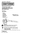
I CRRFTSMRN°I
25cc/1.5 cu.in. 2-Cycle
210 MPH/450 CFM
GASOLINE POWERED
BLOWERNAC
Model No.
358.794763
•
Safety
• Assembly
•
•
Operation
Maintenance
•
Parts
•
Espa_ol,
List
p. 21
Read and follow all Safety Rules and Operating
WARNING:
Instructions before first use of this product.
i_
For answers
questionsor about
this pm,
product:
Call
7 am-7 to
pm,your
Mon.-Sat.,
10 am-7
Sun.
1-800-235-5878
Sears,
Roebuck
545218615
(Hours
and Co., Hoffman
Rev. 6 5/31/09
BRW
listed are Central Time)
Estates,
IL 60179
U.S.A.
Warranty Statement
Identification of Safety Symbols
Safety Rules
Assembly
Operation
Maintenance
2
2
4
6
9
12
Storage
Troubleshooting
Table
Emissions Statement
Parts List
Spanish
Parts and Ordering
14
15
16
18
21
Back Cover
CRAFTSMAN
FU LL WARRANTY
If this Craftsman product fails due to a defect in material or workmanship within two years
from the date of purchase, return it to any Sears store, Parts & Repair Service Center,
or other Craftsman outlet in the United States for free repair (or replacement if repair
proves impossible).
This warranty applies for only 90 days if this product is ever used for commercial or
rental purposes.
This warranty covers ONLY defects in material and workmanship.
Sears will
NOT pay for:
• Expendable items that can wear out from normal use within the warranty period,
such as the vacuum bag, filter or spark plug.
• Repairs necessary because of accident or failure to operate or maintain the
product according to all supplied instructions.
• Preventive maintenance, or repairs necessary due to improper fuel mixture,
contaminated or stale fuel.
This warranty gives you specific legal rights, and you may also have other rights
which vary from state to state.
Sears, Roebuck and Co., Hoffman Estates, IL 60179
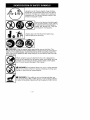
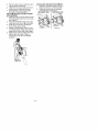
_WARNING:
This unit can be dangerous!
improper use can cause serious injury.
Careless
or
Read your operator's manual carefully until you completely understand and can follow all warnings and safety rules before
operating the unit. Failure to do so can result in serious injury.
Save operator's manual.
The blower can throw objects
violently. You can be blinded or
injured. Always wear hearing
protection and safety glasses
marked Z87. Always wear
heavy, long pants, long sleeves,
boots and gloves.
Hazard
zone
forthrown
objects.
Keep
children,
bystanders,
andanimals
away
fromworkareaa
minimum
of30feet(10meters)
when
starting
or
operating
unit.Donotpointblower
nozzle
inthe
direction
ofpeople
orpets.
O
Do not wear jewelry, loose clothing,
or clothing with loosing hanging
straps, ties, tassels, etc. They can
be caught in moving parts.
secure
ha'r
ab°ve
sh°u'der'ength.
before cleaning or servicing.
I
_
O
_
Always stop u]nit and disconnect
spark plug
_, WARNING:
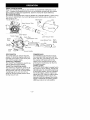
Stop the engine before opening the vacuum inlet door. The
engine must be stopped and the impeller blades no longer turning to avoid serious
injury from the rotating blades. Gently tilt the handle of the screwdriver toward the
back of the unit to release the latch while pulling up on the vacuum inlet cover with
your other hand.
I
@
When using the vacuum attachment, the unit is designed to
pick up dry material such as leaves, grass, small twigs, and bits
of paper. Do not vacuum stones, gravel, metal, broken glass,
etc., to avoid severe damage to the impeller.
1c_rusWeAt
hReNulNtGn:e
Firre hazmardorNpVa_l_
sm(iiX'cP°_rng rsst° rktngt Sopline
flames, or work that can cause sparks).
_, WARNING:
The muffler is very hot during and after use.
Do not touch the muffler, muffler guard, or surrounding surfaces,
or allow combustible material such as dry grass or fuel to do so.
• Donotoperate
unitwhenyouare
_WARNING:Failure
tofollow
all
tired,ill,upset,
orifyouareunder
the
Safety
Rules
andPrecautions
canreinfluence
ofalcohol,
drugs,
ormedisultinserious
injury.
cation.
• Keep
children,
bystanders,
andaniKNOW
YOUR
UNIT
mals
away
fromworkareaamini• Read
youroperator's
manual
careof30feet(10meters)
when
fullyuntilyoucompletely
understand mum
starting
oroperating
unit.Donot
andcanfollow
allwarnings
and
blower
nozzle
inthedirection
of
safety
rules
before
operating
theunit. point
• Restrict
unittousers
whounderpeople
orpets.
stand
andwillfollow
allwarnings
and HANDLE FUEL WITH CAUTION, IT IS
safety
rules
inthismanual.
HIGHLY FLAMMABLE
Eliminate all sources of sparks or
_,WARNING:
Inspect
areabefore • flame
(including smoking, open
starting
unit.Remove
alldebris
and
flames, or work that can cause
hard
objects
suchasrocks,
glass,
in the areas where fuel is
wire,etc.thatcanricochet,
bethrown, sparks) poured,
or stored.
orotherwise
cause
injury
ordamage • mixed,
Mix and pour fuel in an outdoor area;
during
operation.
store fuel in a cool, dry, well ventilated
Useyourunitasablower
for:
place; use an approved, marked con• Sweeping
debris
orgrass
clippings
for all fuel purposes.
fromdriveways,
sidewalks,
patios,
etc. • tainer
Do not smoke while handling fuel or
• Blowing
grass
clippings,
straw,
or
operating the unit.
leaves
intopiles,
around
joints,
orbe- • while
Make sure the unit is properly astween
bricks.
sembled and in good operating conUseyourunitasavacuum
for:
dition.
• Picking
updrymaterial
suchas
leaves,
grass,
small
twigs,
andbitsof • Do not fill fuel tank while engine is
running.
paper.
spilling fuel or oil. Wipe up fuel
• Forbestresults
during
vacuum
use, • Avoid
spills before starting engine.
operate
yourunitathighspeed.
• Move
slowly
backandforthoverthe • Move at least 10 feet (3 meters)
material
asyouvacuum.
Avoid
forc- away from fuel and fueling site before starting engine.
ingtheunitintoa pileofdebris
as
• Always store gasoline in a container
thiscanclogtheunit.
• Keep
thevacuum
tubeabout
aninch approved for flammable liquids.
above
theground
forbestresults.
OPERATE YOUR UNIT SAFELY
PLAN
AHEAD
Stop the engine be• Always
wear
eyeprotection
when
op- _ILWARNING:
erating,
servicing,
orperforming
main- fore opening the vacuum inlet door. The
tenance
onunit.Wearing
eyeprotec- engine must be stopped and the impeltionwillhelptoprevent
rocks
ordebris ler blades no longer turning to avoid serious injury from the rotating blades.
frombeing
blown
orricocheting
into
• Inspect unit before each use for
eyes
andfacewhich
canresult
in
worn, loose, missing, or damaged
blindness
and/or
serious
injury.
Eye
parts. Do not use until unit is in
protection
should
bemarked
Z87.
proper working order.
• Always
wear
footprotection.
Donot
• Keep outside surfaces free from oil
gobarefoot
orwear
sandals.
• Always
wear
respirator
orfacemask and fuel.
when
working
withunitindusty
envi- • Never start or run engine inside a
ronments.
closed room, building or other unarea. Breathing exhaust
• Secure
hairabove
shoulder
length. ventilated
fumes can kill.
Secure
orremove
jewelry,
loose
• To avoid static electricity shock, do
clothing,
orclothing
withloosely
hanging
straps,
ties,tassels,
etc.
not wear rubber gloves or any other
Theycanbecaught
inmoving
parts. insulated gloves while operating unit.
• Donotsetunitonanysurface
except in the operator's manual performed
aclean,
hard
area
while
engine
isrun- by a Sears Service Center.
ning.
Debris
suchasgravel,
sand,
• Use only recommended
Craftsman
dust,
grass,
etc.could
bepicked
upby replacement parts; use of any other
theairintake
andthrown
outthrough parts may void your warranty and
cause damage to your unit.
discharge
opening,
damaging
unit,
• Empty fuel tank before storing the
property,
orcausing
serious
injury
to
unit. Use up fuel left in carburetor by
bystanders
oroperator.
starting engine and letting it run until
• Avoid
dangerous
environments.
Do
it stops.
notuseinunventilated
areas
or
not use any accessory or attachwhere
explosive
vapors
orcarbon • Do
other than those recommended
monoxide
buildupcould
bepresent. ment
manufacturer for use with your unit.
• Donotoverreach
orusefromunsta- • by
blesurfaces
suchasladders,
trees, Do not store the unit or fuel in a closed
where fuel vapors can reach
steep
slopes,
rooftops,
etc.Keep
firm area
sparks or an open flame from hot
footing
andbalance
atalltimes.
water heaters, electric motors or
• Never
place
objects
inside
the
furnaces, etc.
blower
tubes;
always
direct
theblow- • switches,
Store in a dry area out of reach of
ingdebris
away
frompeople,
anichildren.
mals,
glass,
andsolidobjects
such
astrees,
automobiles,
walls,etc.The SAFETY NOTICE: Exposure to vibraforceofaircancause
rocks,
dirt,or tions through prolonged use of gasoline powered hand tools could cause
sticks
tobethrown
ortoricochet
blood vessel or nerve damage in the
which
canhurtpeople
oranimals, fingers,
and joints of people
break
glass,
orcause
other
damage. prone tohands,
circulation disorders or abnor• Never
rununitwithout
theproper
mal swelling. Prolonged use in cold
equipment
attached.
When
using
has been linked to blood vesyourunitasablower,
always
install weather
sel damage in otherwise healthy
blower
tubes.
When
using
theopIf symptoms occur such as
tional
vacuum
kit,always
install
vac- people.
numbness, pain, loss of strength,
uumtubes
andvacuum
bagassemin skin color or texture, or loss
bly.Make
surevacuum
bagassem- change
of feeling in the fingers, hands, or
blyiscompletely
zipped.
discontinue the use of this tool
• Check
airintake
opening,
blower joints,
and seek medical attention. An
tubes,
andvacuum
tubes
frequently,antivibration system does not guaranalways
withengine
stopped
and
avoidance of these problems.
spark
plugdisconnected.
Keep
vents tee the who
operate power tools on a
anddischarge
tubes
freeofdebris Users
continual and regular basis must moniwhich
canaccumulate
andrestrict tor
closely their physical condition and
proper
airflow.
the condition of this tool.
• Never
place
anyobject
inairintake SPECIAL NOTICE: This unit is
opening
asthiscould
restrict
proper
air equipped with a temperature limiting
flowandcause
damage
totheunit.
and spark arresting screen
• Never
useforspreading
chemicals, muffler
which meets the requirements of Califertilizers,
orother
substances
which fornia
Codes 4442 and 4443. All U.S.
maycontain
toxicmaterials.
forest land and the states of California,
• Toavoid
spreading
fire,donotuse Idaho, Maine, Minnesota, New Jersey,
nearleaforbrush
fires,
fireplaces, Oregon, and Washington require by
barbecue
pits,ashtrays,
etc.
law that many internal combustion en• Useonlyforjobsexplained
inthis
gines be equipped with a spark arrestmanual.
ing screen. If you operate in a locale
MAINTAIN YOUR UNIT PROPERLY
WARNING:
Disconnect spark
plug before performing maintenance
except for carburetor adjustments.
• Have all maintenance other than the
recommended
procedures described
where such regulations exist, you are
legally responsible for maintaining the
operating condition of these parts. Failure to do so is a violation of the law.
Refer to the MAINTENANCE section for
information on maintenance of the
muffler and spark arresting screen.
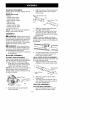
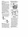
CARTON
CONTENTS
Check
carton
contents
against
thefollowing
list.
3.
Align the slots on the lower blower
tube with the tabs on the upper
blower tube.
Model 358,794763
• Blower
•
•
•
•
er BIow.,_
er TUbTe
b
Upper blower tube
Lower blower tube
High velocity nozzle
Elbow tube
_-__
• Vacuum bag
• Upper vacuum tube
• Lower vacuum tube
• 2-Cycle engine oil
NOTE: It is normal for the fuel filter to
rattle in the empty fuel tank.
4.
5.
ASSEMBLY
_ILWARNING:
Stop engine and be
sure the impeller blades have stopped
turning before opening the vacuum inlet door or attempting to insert or remove the vacuum tubes. The rotating
blades can cause serious injury.
6.
ASSEMBLY
To remove the tubes, turn the knob
counterclockwise
to loosen the
tubes; remove the tubes.
HIGH-SPEED
NOZZLE ASSEMBLY
When greater air speed is desired, use
the high-speed nozzle.
1. Align the slots on the nozzle with
the tabs on the lower blower tube.
BLOWER TUBE ASSEMBLY
If you have already assembled your
unit for use as a vacuum, remove the
vacuum tubes and collection bag.
1. Align the rib on the upper blower
tube with the groove in the blower
outlet; slide the tube into place.
NOTE: Knob must be loose enough to
allow blower tube to be inserted in
blower outlet. Loosen knob by turning
counterclockwise.
High-Speed
Nozzle
/
Lower Blower
Tube
2.
Blower Outlet
3.
Rib
Tab
Slide the nozzle onto the lower
blower tube.
Turn the nozzle clockwise until a
click is felt to secure the nozzle to
the lower blower tube.
VACUUM
Groove
2,
Slide the lower blower tube onto
the upper blower tube.
Turn the lower blower tube clockwise until a click is felt to secure
the lower blower tube to the upper
blower tube.
NOTE: When the upper and lower
blower tubes are assembled together
properly, the arrows on both tubes will
be aligned.
WARNING:
If you receive your
unit assembled, repeat all steps to ensure your unit is properly assembled
and all fasteners are secure.
•
A standard screwdriver is required
for assembly.
BLOWER
Lower Blower Tube
ASSEMBLY
VACUUM BAG ASSEMBLY
1. Open the zipper on the vacuum
bag and insert the elbow tube.
Secure the tube by turning the
knob clockwise.
-6-
2.
Push the small end ofthe elbow
tube through the small opening in
the bag.
3,
Rib
Zipper
Opening
release the latch while pulling up
on the vacuum inlet cover with your
other hand.
Hold the vacuum inlet cover open
until upper vacuum tube is installed.
Vacuum
Inlet
Cover
".,
Small Opening
NOTE: Make sure edge of the small
opening is flush against the flared area
of the elbow tube, and the rib on the
elbow tube is on the bottom.
3. Close the zipper on the bag. Make
sure the zipper is closed completely.
4. Remove blower tubes from engine.
Inlet
4,
Align the tabs on the inside of the
vacuum inlet with the slots in the
upper vacuum tube.
....Groove
/
Tab
5,
Push the upper vacuum tube into
the vacuum inlet. Turn the tube
counterclockwise until a click is felt
to secure the tube to the blower unit.
6.
Align slanted end of lower vacuum
tube as shown. Firmly push lower
vacuum tube into upper vacuum
tube.
5.
Insert the elbow tube into the blower outlet. Make sure elbow tube rib
is aligned with the blower outlet
groove.
6. Turn knob clockwise to secure elbow tube.
VACUUM TUBE ASSEMBLY
_ILWARNING:
Stop engine and be
sure the impeller blades have stopped
turning before opening the vacuum inlet
door or attempting to insert or remove
the vacuum or blower tubes. The rotating blades can cause serious injury.
1. Insert the tip of a screwdriver into
the latch area of the vacuum inlet.
I Ea{_hArea
Blower
S,
Slanted end of
lower vacuum tube
\
Vacuum Inlet Cover
2.
Slot
Gently tilt the handle of the screwdriver toward the front of the unit to
_l_
--
_,--
HOW TO CONVERT UNIT FROM
VACUUM USE TO BLOWER USE
1. Remove the elbow tube and vacuum bag by turning the knob counterclockwise to loosen the elbow
tube.
2. Remove
thevacuum
tubesbyturn- SHOULDER STRAP ATTACHMENT
1. Pass the shoulder strap over your
ingthetubes
clockwise.
3. Close
thevacuum
inletcover
and
head and onto your left shoulder.
make
sureitislatched
closed.
2. Snap the hook onto the retainer
4. Reinstall
theblower
tubes(see
(see following illustration).
BLOWER
TUBE
ASSEMBLY).
BLOWER USE
I VACUUM USE
VACUUM
BAGSHOULDER
STRAP
ADJUSTMENT
1. Hold
theunitasshown
withthemufflerside
facing
away
fTom
yourbody
andclothes.
2. Pass
theshoulder
strapoveryour
headandontoyourrightshoulder.
3. Extend
yourleftarmtoward
the
rearofthevacuum
bag.
4. Adjust
shoulder
strap
until
thevacuumbag/shoulder
strap
seam
liesbetween
yourthumb
andindex
finger.
5. Make
sureairflows
freely
fromthe
elbow
tubeintobag.Ifbagis
kinked,
theunitwillnotoperate
properly.
et ,ne
\
b
-8-
KNOW YOUR BLOWER
READ THIS OPERATOR'S MANUAL AND SAFETY RULES BEFORE OPERATING YOUR
UNIT. Compare the illustrations with your unit to familiarize yourself with the location
of the various controls and adjustments. Save this manual for future reference.
MULCHING BLADES
Your blower is equipped with mulching blades as a standard feature. When using
the vacuum attachment, the mulching blades automatically reduce debris at a
ratio of up to 16:1.
Throttle Position Lever
Elbow Tube
Upper Vacuum Tube
STOP Switch
Throttle Trigger
Starter
i
Spark
Lower Vacuum Tube
Plug
Upper Blower Tube
Lower Blower Tube
Rope
HighSpeed
Nozzle
Fuel Mix
Fill Cap _k
Start Lever
/
Primer
Bulb
Vacuum Handle
STOP SWITCH
The STOP switch is used to stop the
engine. To stop the engine, push and
hold the STOP switch in the STOP position until the engine stops.
THROTTLE TRIGGER
The THROTTLE TRIGGER is used to select the desired engine speed.
THROTTLE
POSITION LEVER
The THROTTLE POSITION LEVER is designed to allow setting engine speed
during blower use only. To avoid causing damage to the unit, DO NOT attempt to use the throttle position lever
during vacuum use.
PRIMER BULB
The PRIMER BULB removes air from
the carburetor and fuel lines and fills
them with fuel. This allows you to start
the engine with fewer pulls on the
starter rope. Activate primer bulb by
pressing it and allowing it to return to
its original position.
START LEVER
The START LEVER helps to supply fuel to
the engine to aid in starting. Activate the
starting system by moving the start lever
to the START position. DO NOT squeeze
the throttle trigger until the engine has
started and runs. After the engine starts,
allow the engine to warm-up 10-15
seconds, then fully squeeze the throttle
trigger to deactivate the starting system
(start lever returns to RUN position).
-9-
OPERATING TIPS
• While vacuuming or blowing debris,
hold the unit with the muffler side facing away from your body and clothes
(see OPERATING POSITION below).
• To reduce the risk of hearing loss
associated with sound level(s), hearing protection is required.
• To reduce the risk of injury associated
with contacting rotating parts, stop the
engine before installing or removing
attachments. Do not operate without
guard(s) in place.
• Operate power equipment only at reasonable hours-not early in the morning or late at night when people might
be disturbed. Comply with times listed
in local ordinances. Usual recommendations are 9:00 a.m. to 5:00 p.m.,
Monday though Saturday.
• To reduce noise levels, limit the number of pieces of equipment used at
any one time.
• To reduce noise levels, operate power blowers at the lowest possible
throttle speed to do the job.
• Use rakes and brooms to loosen
debris before blowing.
• In dusty conditions, slightly dampen
surfaces or use a mister attachment
when water is available.
• Conserve water by using power blowers instead of hoses for many lawn
and garden applications, including
areas such as gutters, screens, patios,
grills, porches, and gardens.
• Watch out for children, pets, open
windows, or freshly washed cars.
Blow debris away safely.
• Use the full blower nozzle extension
so the air stream can work close to
the ground.
• After using blowers and other equipment, CLEAN UP! Dispose of debris
in trash receptacles.
-10-
OPERATING
POSITION
Blower
BEFORE
Vacuum
STARTING
_LWARNING:
ENGINE
Be sure to read the
fuel information in the safety rules
before you begin. If you do not
understand the safety rules, do not
attempt to fuel your unit. Call
1-800-235-5878.
FUELING ENGINE
,_LWARNING:
Remove fuel cap
slowly when refueling.
This engine is certified to operate on unleaded gasoline. Before operation, gasoline must be mixed with a good quality
synthetic 2-cycle air-cooled engine oil.
We recommend Craftsman brand synthetic oil. Mix gasoline and oil at a ratio
of 40:1. A 40:1 ratio is obtained by mixing 3.2 fluid ounces of oil with 1 gallon of
unleaded gasoline. Included with this
blower is a 3.2 ounce container of oil.
Pour the entire contents of this container
into 1 gallon of gasoline to achieve the
proper fuel mixture. DO NOT USE automotive oil or boat oil. These oils will
cause engine damage. When mixing
fuel, follow instructions printed on container. Once oil is added to gasoline,
shake container momentarily to assure
that the fuel is thoroughly mixed. Always
read and follow the safety rules relating
to fuel before fueling your unit.
CAUTION:
Never use straight gasoline
in your unit. This will cause permanent
engine damage and void the limited
warranty.
FUEL REQUIREMENTS
This engine requires the use of
minimum 87 octane [R+M]/2 clean
gasoline.
IMPORTANT
Use of alcohol blended fuels (called
gasohol or using ethanol or methanol)
can cause major engine performance
and durability problems.
_/L WARNING:
Alternative fuels (not
gasoline) such as E-15 (15% alcohol),
E-20 (20% alcohol), E-85 (85% alcohol)
are NOT classified as gasoline and are
NOT approved for use in 2-stroke gasoline engines. Use of alternative fuels will
cause problems such as: improper
clutch engagements, overheating, vapor
lock, power loss, lubrication deficiency,
deterioration of fuel lines, gaskets and
internal carburetor components, etc. Alternative fuels cause high moisture absorption into the fuel/oil mixture leading
to oil and fuel separation.
HOW TO STOP YOUR ENGINE
• Release the throttle trigger.
• Push and hold the STOP switch in the
STOP position until the engine stops.
HOW TO START YOUR ENGINE
_ILWARNING:
2.
3.
Slowly press the primer bulb 6 times.
Move the start lever to the START
position.
St n t2r
You MUST make sure
the tubes are secure before using the
unit.
• Fuel engine. Move at least 10 feet (3
meters) away from the fueling site.
• Hold the unit in the starting position
as shown. Make sure the blower end
is directed away from people, animals, glass, and solid objects.
STARTING
.4
Start Jzz_/!
Lever
_/_
Primer
Bulb
POSITION
4.
Blower
J
STARTING
A COLD
ENGINE
(or
warm engine after running
out of fuel)
1. Move the throttle position lever
(cruise control) to the idle position.
Throttle
Position
Lever
(Cruise
Control)
/
WARNING:
When starting engine,
hold the unit as illustrated. Do not set
unit on any surface except a clean, hard
area when starting engine or while engine is running. Debris such as gravel,
sand, dust, grass, etc. could be picked
up by the air intake and thrown out
through the discharge opening, damaging the unit or property, or causing serious injury to bystanders or the operator.
-11
This unit has the Sim-pulTM starting
system. You do not have to pull the
starter rope handle sharply or
briskly. Pull starter rope handle 5
times with a controlled and steady
motion (no more than 3 times
above 90°F). If engine starts and
runs prior to 5 pulls, allow engine to
run for 5 seconds; then, fully
squeeze the throttle trigger to disengage the starting system (start
lever returns to RUN position).
Steps 5 and 6 are not necessary.
5. Fully squeeze the throttle trigger to
disengage the starting system (start
lever returns to RUN position).
6. Pull starter rope handle with a controlled and steady motion while
squeezing throttle trigger until
engine starts and runs.
STARTING A WARM ENGINE
1. Squeeze and hold the throttle trigger.
-
2.
Pull starter rope handle with a controlled and steady motion while
squeezing throttle trigger until engine starts and runs.
NOTE: Normally, the warm starting
procedure can be used within 5-10
minutes after the unit is turned off. If
the unit sits for more than 10 minutes
without being used, it will be necessary
to start the unit by following the steps
under STARTING A COLD ENGINE or following the starting instruction steps
shown on the unit.
CUSTOMER
_,
STARTING A FLOODED ENGINE
Flooded engines can be started by moving the start lever to the RUN position
and fully squeezing the throttle trigger.
Pull the starter handle repeatedly while
squeezing throttle trigger until engine
starts and runs. This could require pulling the starter handle many times, depending on how badly the unit is
flooded. If the unit still doesn't start,
refer to the TROUBLESHOOTING TABLE
or call 1-800-235-5878.
RESPONSIBILITIES
WARNING:
Disconnect the spark plug before performing maintenance,
service, or adjustments.
CARE & MAINTENANCE
TASK
WHEN TO PERFORM
Check for loose fasteners
Check for damaged
Before each use
and parts
Before each use
or worn parts
Inspect and clean unit and labels
Clean air filter
After each use
Replace
Yearly
Every 5 hours of operation
spark plug
Replace fuel filter
Check muffler mounting
Yearly
screws
Yearly
,_ WARNING:
Avoid touching muffler unless engine and muffler are cold.
A hot muffler can cause serious burns.
_ILWARNING:
Stop engine and be
sure the impeller blades have stopped
turning before opening the vacuum inlet door or attempting to insert or remove the vacuum or blower tubes.
The rotating blades can cause serious
injury. Always disconnect the spark
plug before performing maintenance or
accessing movable parts.
GENERAL RECOMMENDATIONS
The warranty on this unit does not cover items that have been subjected to
operator abuse or negligence. To receive full value from the warranty, the
operator must maintain unit as instructed in this manual. Various adjustments
will need to be made periodically to
properly maintain your unit.
-12-
CHECK FOR LOOSE
FASTENERS AND PARTS
• Muffler
• Spark Plug Boot
• Air Filter
• Housing Screws
CHECK FOR DAMAGED OR
WORN PARTS
Contact Sears Service Center for replacement of damaged or worn parts.
• Fuel Tank - Do not use unit if fuel tank
shows signs of damage or leaks.
• Vacuum Bag - Do not use vacuum
bag if it is torn or damaged.
INSPECT AND CLEAN UNIT
AND LABELS
• After each use, inspect complete unit
for loose or damaged parts. Clean
the unit using a damp cloth with a
mild detergent.
• Wipe off unit with a clean dry cloth.
CLEAN AIR FILTER
A dirty air filter decreases engine performance and increases fuel consumption and harmful emissions. Always
clean after every 5 hours of operation.
CHECK MUFFLER MOUNTING
SCREWS
Once each year, ensure muffler
mounting screws are secure and tightened properly to prevent damage.
Button ,_'_\
Air Filter
X_'_
Air Filter Cover "__
1/
Y
Cleaning the air filter:
1. Clean the cover and the area
around it to keep debris from falling
into the carburetor chamber when
the cover is removed.
NOTE: Move start lever to RUN position before opening air filter cover.
2. Open air filter cover by pushing
button (see illustration). Remove
air filter.
NOTE: Do not clean filter in gasoline
or other flammable solvent. Doing so
can create a fire hazard or produce
harmful evaporative emissions.
3. Wash the filter in soap and water.
4. Allow filter to dry.
5. Apply a few drops of oil to the filter;
squeeze filter to distribute oil.
6. Replace parts.
REPLACE SPARK PLUG
Replace spark plug each year to ensure
the engine starts easier and runs better.
Set spark plug gap at 0.025 inch. Ignition timing is fixed, nonadjustable.
1. Twist, then pull off spark plug boot.
2. Remove spark plug from cylinder
and discard.
3. Replace with Champion RCJ-6Y
spark plug and tighten securely
with a 3/4 inch socket wrench.
4. Reinstall the spark plug boot.
REPLACE FUEL FILTER
To replace fuel filter, drain unit by running it dry of fuel, then remove fuel
cap/retainer assembly from tank. Pull
filter from tank and remove it from the
fuel line. Install new fuel filter on fuel
line; reinstall parts.
Fuel Filter _
Fuel Line
_
-13-
Muffler
Mounting Screw
INSPECT MUFFLER AND SPARK
ARRESTING
SCREEN
,_ik WARNING:
The muffler on this
product contains chemicals known to
the State of California to cause cancer.
As the unit is used, carbon deposits
build up on the muffler and spark arresting screen, and must be removed
to avoid creating a fire hazard or affecting engine performance.
Muffler Cover
_
_
Spark
creen
_!
_
"_j_.[_,_ Arresting
Screws
Replace the spark arresting screen every 50 hours of operation or if any damage or breaks in the screen are noted.
NOTE: Do not attempt to clean the
spark arresting screen.
1. Remove 3 screws from muffler cover. Remove muffler cover.
2. Loosen and remove 4 screws from
the muffler hood.
3. Remove the muffler hood and spark
arresting screen.
4. Install new spark arresting screen.
5. Reinstall muffler hood and 4
screws. Tighten screws securely.
6. Reinstall muffler cover and 3
screws. Tighten securely.
NOTE: If any part of the muffler is
cracked, broken or damaged, we recommend that the muffler be replaced.
CARBURETOR
IDLE SPEED
ADJUSTMENT
The carburetor has been carefully set
at the factory. Adjustments may be
necessary if you notice any of the following conditions:
• Engine will not idle when the throttle is
released.
To adjust idle speed:
Allow engine to idle. Adjust speed until
engine runs without stalling (idle speed
too slow).
• Turn idle speed screw clockwise to
increase engine speed if engine
stalls or dies.
• Turn idle speed screw counterclockwise to decrease engine speed.
,_ WARNING:
Perform the following
steps after each use:
• Allow engine to cool, and secure the
unit before storing or transporting.
• Store unit and fuel in a well ventilated area where fuel vapors cannot
reach sparks or open flames from
water heaters, electric motors or
switches, furnaces, etc.
• Store unit with all guards in place.
Position unit so that any sharp object
cannot accidentally cause injury.
• Store unit and fuel well out of the
reach of children.
SEASONAL STORAGE
Prepare unit for storage at end of season or if it will not be used for 30 days
or more. If your unit is to be stored for
a period of time:
• Clean the entire unit before lengthy
storage.
• Store in a clean dry area.
• Lightly oil external metal surfaces.
FUEL SYSTEM
Empty the fuel system before storage for
30 days or longer. Drain the gas tank,
start the engine and let it run until the
fuel lines and carburetor are empty. Use
fresh fuel next season. Under FUELING
ENGINE in the OPERATION section of this
manual, see message labeled
IMPORTANT regarding the use of gasohol in your engine.
-14-
Idle Speed Screw\_
C'over
If you require further assistance or are
unsure about performing this procedure, contact your Sears Service Center or call our customer assistance
help line at 1-800-235-5878.
Fuel stabilizer is an acceptable alternative in minimizing the formation of fuel
gum deposits during storage. Add stabilizer to gasoline in fuel tank or fuel storage container. Follow the mix instructions found on stabilizer container. Run
engine at least 3 minutes after adding
stabilizer.
Craftsman 40:1,2-cycle
engine oil (air
cooled) is already blended with fuel
stabilizer. If you do not use this Sears
oil, you can add a fuel stabilizer to your
fuel tank.
ENGINE
• Remove spark plug and pour 1 teaspoon of 40:1,2-cycle
engine oil (air
cooled) through the spark plug opening. Slowly pull the starter rope 8 to
10 times to distribute oil.
• Replace spark plug with new one of
recommended type and heat range.
• Clean air filter.
• Check entire unit for loose screws,
nuts, and bolts. Replace any damaged, broken, or worn parts.
• At the beginning of the next season,
use only fresh fuel having the proper
gasoline to oil ratio.
OTHER
• Do not store gasoline from one season to another.
• Replace your gasoline can if it starts
to rust.
TROUBLESHOOTING
TABLE
WARNING:
Always stop unit and disconnect spark plug before performing any of the recommended remedies below other than remedies that require operation of the unit.
TROUBLE
CAUSE
Engine will not
start.
1. Engine flooded.
i 1. See "Starting a Flooded
in Operation section.
REMEDY
2. Fuel tank empty.
2. Fill tank with correct fuel mixture.
3. Install new spark plug.
;;4. Check for dirty fuel filter; replace.
Check for kinked or split fuel line;
repair or replace.
i 5. Contact Sears Service (see back cover).
3. Spark plug not firing.
4. Fuel not reaching
carburetor.
5. Compression
Engine will not
idle properly.
il.
low.
Fuel not reaching
carburetor.
::2. Carburetor requires
adjustment.
3. Crankshaft seals worn.
4. Compression
Engine will not
accelerate,
lacks power, or
dies under a
load.
low.
Engine
runs hot.
2. Fuel not reaching
carburetor.
i 3. Spark plug fouled.
}
5. Contact
6. Contact
,
Choke partially on.
i2. Fuel mixture incorrect.
i 3. Air filter dirty.
i4. Carburetor requires
adjustment.
1. Fuel mixture incorrect.
i12. Spark plug incorrect.
3. Carburetor requires
adjustment.
4. Carbon
i 1. Check for dirty fuel filter; replace.
Check for kinked or split fuel line;
repair or replace.
i 2. See "Carburetor Idle Speed Adjustment''
i
in Service and Adjustments Section.
3. Contact Sears Service (see back cover).
4. Contact Sears Service (see back cover).
1. Clean or replace air filter.
2. Check for dirty fuel filter; replace.
Check for k nked or sp t fue ne;
repair or replace.
i3. Clean or replace spark plug
and re-gap.
i4. Contact Sears Service (see back cover)•
:i1. Air filter dirty.
adjustment.
Carbon build up.
ii I Compression
Carburetor
requires
low.
Engine smokes
excessively.
Engine"
-15-
Service (see back cover).
Service (see back cover).
i11. Adjust choke.
;;2. Empty fuel tank and refill with
correct fuel mixture.
;;3. Clean or replace air filter.
i4. Contact Sears Service (see back cover).
i
• See "Fueling
section.
i2. Replace
build up.
Sears
Sears
Engine" in Operation
with correct spark plug.
3. Contact
Sears
Service (see back cover).
4• Contact
Sears
Service (see back cover).
YOUR WARRANTY RIGHTS AND OBLIGATIONS: The U.S. Environmental
Protection Agency/California Air Resources Board and Sears, Roebuck and
Co., U.S.A., are pleased to explain the
emissions control system warranty on
your year 2009 and later small off-road
engine. In California, all small off-road
engines must be designed, built, and
equipped to meet the State's stringent
anti-smog standards. Sears must warrant the emission control system on your
small off-road engine for the periods of
time listed below provided there has
been no abuse, neglect, or improper
maintenance of your small off-road engine. Your emission control system includes parts such as the carburetor, the
ignition system and the fuel tank. Where
a warrantable condition exists, Sears will
repair your small off-road engine at no
cost to you. Expenses covered under
warranty include diagnosis, parts and
labor. MANUFACTURER'S
WARRANTY COVERAGE: If any emissions related part on your engine (as listed under Emissions Control Warranty Parts
List) is defective or a defect in the materials or workmanship of the engine
causes the failure of such an emission
related part, the part will be repaired or
replaced by Sears. OWNER'S WARRANTY RESPONSIBILITIES:
As the
small off-road engine owner, you are
responsible for the performance of the
required maintenance listed in your operator's manual. Sears recommends that
you retain all receipts covering maintenance on your small off-road engine,
but Sears cannot deny warranty solely
for the lack of receipts or for your failure
to ensure the performance of all scheduled maintenance. As the small off-road
engine owner, you should be aware that
Sears may deny you warranty coverage
if your small off-road engine or a part of
it has failed due to abuse, neglect, improper maintenance, unapproved modifications, or the use of parts not made or
approved by the original equipment
manufacturer. You are responsible for
presenting your small off-road engine to
a Sears authorized repair center as
soon as a problem exists. Warranty repairs should be completed in a reasonable amount of time, not to exceed 30
days. If you have any questions regard-
-16-
ing your warranty rights and responsibilities, you should contact your nearest
authorized service center, call Sears at
1-800-469-4663,
or send e-mail correspondence to emission.warranty@
HCOP-emission.com.
WARRANTY
COMMENCEMENT
DATE: The warranty period begins on the date the small
off-road engine is purchased. LENGTH
OF COVERAGE: This warranty shall be
for a period of two years from the initial
date of purchase. WHAT IS COVERED: REPAIR OR REPLACEMENT
OF PARTS. Repair or replacement of
any warranted part will be performed at
no charge to the owner at an approved
Sears Service Center. If you have any
questions regarding your warranty rights
and responsibilities, you should contact
your nearest authorized service center,
call Sears at 1-800-469-4663,
or send
e-mail correspondence
to emission.
warranty@ HCOP- emission.com.
WARRANTY PERIOD: Any warranted
part which is not scheduled for replacement as required maintenance, or which
is scheduled only for regular inspection
to the effect of "repair or replace as necessary" shall be warranted for 2 years.
Any warranted part which is scheduled
for replacement as required maintenance shall be warranted for the period
of time up to the first scheduled replacement point for that part. DIAGNOSIS:
The owner shall not be charged for
diagnostic labor which leads to the determination that a warranted part is defective if the diagnostic work is performed at an approved Sears Service
Center. CONSEQUENTIAL
DAMAGES:
Sears may be liable for damages to other engine components caused by the
failure of a warranted part still under
warranty. WHAT IS NOT COVERED: All
failures caused by abuse, neglect, or improper maintenance are not covered.
ADD-ON OR MODIFIED PARTS: The
use of add-on or modified parts can be
grounds for disallowing a warranty claim.
Sears is not liable to cover failures of
warranted parts caused by the use of
add-on or modified parts. HOW TO
FILE A CLAIM: If you have any questions regarding your warranty rights and
responsibilities, you should contact your
nearest authorized service center, call
Sears at 1-800-469-4663,
or send
e-mail correspondence
to emission.
warranty@ HCOP- emission.com.
WHERE TO GET WARRANTY SERVICE: Warranty services or repairs shall
be provided at all Sears Service Centers. Call 1-800-469-4663
or send
e-mail correspondence
to emission.
warranty@ HCOP- emission.com.
MAINTENANCE, REPLACEMENT
AND REPAIR OF EMISSION RELATED PARTS: Any Sears approved
replacement part used in the performance of any warranty maintenance or
repair on emission related parts will be
provided without charge to the owner if
the part is under warranty. EMISSION
CONTROL WARRANTY PARTS LIST:
Carburetor, air filter (covered up to maintenance schedule), ignition system:
spark plug (covered up to maintenance
schedule), ignition module, muffler including catalyst (if equipped), fuel tank.
MAINTENANCE STATEMENT: The
owner is responsible for the performance of all required maintenance as
defined in the operator's manual.
The information on the product label indicates
Example: (Year) EPA and/or CALIFORNIA.
which standard
61
This engine is certified to be emissions
[]
Moderate
[]
Intermediate
[]
Extended
I
compliant
(50 hours)
(125 hours)
(300 hours)
-17-
sl
your engine is certified.
I
for the following
use: