1
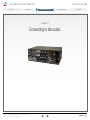
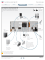
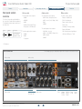
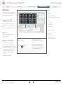
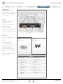
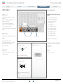
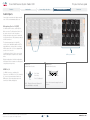
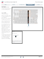
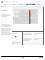
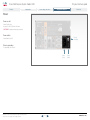
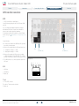
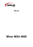
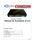
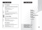
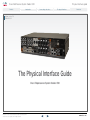
Cisco TelePresence System Codec C90 Contents Introduction Physical interface guide Connecting to the codec The physical interface Contact us Software version TC4 FEBRUARY 2011 The Physical Interface Guide Cisco Telepresence System Codec C90 D14644.03 Codec C90 Physical Interface Guide TC4.1, February 2011. © 2010-2011 Cisco Systems, Inc. All rights reserved. 1 www.cisco.com Cisco TelePresence System Codec C90 Contents Contents Introduction What’s in this guide? TA - ToC Hidden text anchor The top menu bar and the entries in the Table of Contents are all hyperlinks, just click on them to go to the topic. Physical interface guide Connecting to the codec Introduction About this guide................................................................... 4 User documentation......................................................... 4 Connecting to the codec The physical interface The front panel..................................................................... 8 Rear panel sockets overview............................................... 9 The Video Input Matrix....................................................... 10 About the matrix............................................................. 10 Configure the video inputs............................................. 10 The Advanced configuration menu............................ 10 The API commands.................................................... 10 The default values....................................................... 10 Video inputs........................................................................11 Component 1–2 (Y-Pr-Pb)...............................................11 HD-SDI 1–4......................................................................11 Composite 5 / S-Video (YC) 5........................................11 HDMI 1–4.........................................................................12 DVI-I 3 and 5...................................................................12 Video input formats.........................................................13 4 x HDMI inputs, supported formats............................13 4 x HD-SDI inputs, supported formats........................13 2 x DVI-I inputs, supported formats............................13 2 x YPbPr inputs, supported formats..........................13 1 x S-Video/Composite input, supported formats......13 Video outputs......................................................................14 HDMI 1 and 3...................................................................14 DVI-I 2 and 4...................................................................14 Composite 5....................................................................14 D14644.03 Codec C90 Physical Interface Guide TC4.1, February 2011. © 2010-2011 Cisco Systems, Inc. All rights reserved. Contact us Table of Contents Basic setup when connecting to Codec C90...................... 6 We recommend you visit our web site regularly for updated versions of the user documentation. Go to: http://www.cisco.com/go/telepresence/ docs - and navigate in the right pane to find the TelePresence product documentation. The physical interface 2 Video output formats.......................................................14 2 x HDMI and 2 x DVI-I outputs, supported formats...14 1 x Composite output, supported formats..................14 Levels..............................................................................14 Audio inputs....................................................................... 15 Microphone/Line In 1–8 (XLR)........................................ 15 HDMI In 3, 4.................................................................... 15 Line In 1–4 (RCA)............................................................ 16 Audio outputs......................................................................17 Line Out 5–6 (XLR)..........................................................17 HDMI Out 1, 3..................................................................17 Line Out 1–4 (RCA)......................................................... 18 Audio signal levels tables................................................... 19 Audio hardware information table...................................... 20 Volume control table.......................................................... 20 Network connectors........................................................... 21 Ethernet interface........................................................... 21 COM port and Camera Control port.................................. 22 COM port........................................................................ 22 Camera Control port...................................................... 22 Power ................................................................................ 23 Power socket.................................................................. 23 Power switch.................................................................. 23 Chassis grounding.......................................................... 23 GPIO and other connectors............................................... 24 GPIO............................................................................... 24 USB................................................................................ 24 T Link.............................................................................. 24 www.cisco.com Cisco TelePresence System Codec C90 Contents Introduction Introduction Physical interface guide Connecting to the codec The physical interface Contact us Chapter 1 Introduction D14644.03 Codec C90 Physical Interface Guide TC4.1, February 2011. © 2010-2011 Cisco Systems, Inc. All rights reserved. 3 www.cisco.com Cisco TelePresence System Codec C90 Contents Introduction Introduction About this guide The purpose of this document is to describe the physical interface for the Codec C Series listed below.: • Cisco TelePresence System Codec C90 Physical interface guide Connecting to the codec The physical interface Contact us User documentation The user documentation for the Cisco TelePresence systems, running the TC software, have several guides suitable to various user groups. • • • • • • Video conference room primer Video conference room acoustics guidelines Installation guides for the TelePresence systems Software release notes for the TC software Getting started guide for the TelePresence systems User guide for the TelePresence systems • • • • • • • • • • When using the Touch controller, ref. TC4.1 version of the user guide When using the Remote Control, ref. TC4.0 version of the user guide Quick reference guides for the TelePresence systems Administrator guides for the TelePresence systems Camera user guide for the PrecisionHD cameras API reference guides for the Codec C Series TC Console user guide for the Codec C Series Physical interfaces guides for the Codec C Series Regulatory compliance and safety information guides Legal & license information for products using TC software Download the user documentation Go to: http://www.cisco.com/go/telepresence/docs - in the right pane, select: • • TelePresence Peripherals for the PrecisionHD cameras, microphones, Touch unit, and remote controls. TelePresence Solutions Platform for the Codec C Series and Quick Set C20. Software download Go to: D14644.03 Codec C90 Physical Interface Guide TC4.1, February 2011. © 2010-2011 Cisco Systems, Inc. All rights reserved. http://www.cisco.com/cisco/software/navigator.html 4 www.cisco.com Cisco TelePresence System Codec C90 Contents Introduction Physical interface guide Connecting to the Connecting the codec codec The physical interface Contact us Chapter 2 Connecting to the codec D14644.03 Codec C90 Physical Interface Guide TC4.1, February 2011. © 2010-2011 Cisco Systems, Inc. All rights reserved. 5 www.cisco.com Cisco TelePresence System Codec C90 Contents Physical interface guide Introduction Connecting to the Connecting the codec codec The physical interface Basic setup when connecting to Codec C90 Contact us Inputs The illustration shows you the basic setup when connecting the monitor, PC, camera, microphone, loudspeakers (if applicable), LAN and line voltage to your codec. 1 OPTIONAL: Audio from PC Video from PC Outputs Basic Setup The main connectors for basic setup are highlighted in orange. 1 OPTIONAL: Loudspeakers LAN/ Ethernet Power Switch Monitor (Audio from HDMI 1 or Line Out 1–2) First connect the cables, then turn the codec on. Microphone Main camera: Video from PrecisionHD 1080p OPTIONAL: Dual monitor setup Connect the second monitor to HDMI 3 ! Main camera: Camera Control to PrecisionHD 1080p OPTIONAL: You may connect additional microphones Mains Power Cable OPTIONAL: You may connect a second camera. (extra camera not included). Extra camera will require separate power supply and control cabling. Consult the documentation supplied with the extra camera for details. Make sure the codec has been switched off and disconnected from the line voltage whenever connecting or disconnecting other equipment. D14644.03 Codec C90 Physical Interface Guide TC4.1, February 2011. © 2010-2011 Cisco Systems, Inc. All rights reserved. 6 www.cisco.com Cisco TelePresence System Codec C90 Contents Introduction Physical interface guide Connecting to the codec The Thephysical physical interface interface Contact us Chapter 3 The physical interface D14644.03 Codec C90 Physical Interface Guide TC4.1, February 2011. © 2010-2011 Cisco Systems, Inc. All rights reserved. 7 www.cisco.com Cisco TelePresence System Codec C90 Contents Introduction Physical interface guide Connecting to the codec The Thephysical physical interface interface Contact us The front panel There are four LED’s in the front of the Codec: • • • • Power – The POWER LED turns ON when power is connected, otherwise OFF Call – The CALL LED turns ON when there are active calls on the codec, otherwise OFF Infrared – The IR LED flashes when infrared signals are received Alarm – The ALARM LED turns ON when there is no connection to the network, otherwise OFF Power Call D14644.03 Codec C90 Physical Interface Guide TC4.1, February 2011. © 2010-2011 Cisco Systems, Inc. All rights reserved. IR Alarm (infrared) 8 www.cisco.com Cisco TelePresence System Codec C90 Contents Introduction Rear panel sockets overview The Codec C90 provides great flexibility for the connection of audio and video equipment. The illustration below shows the rear panel of the Codec C90. Physical interface guide Connecting to the codec 1 Outputs 1 Basic Setup The main connectors for basic setup are highlighted in orange. Contact us Video sockets Audio sockets Other sockets The video input sockets comprise: The audio input sockets comprise: The other sockets comprise: 4xHDMI 8xXLR Female - Microphone/Line In Ethernet 1 and Ethernet 2 4xHD-SDI 4xRCA - Line In (1 Left, 2 Right, 3 Left, 4 Right) COM - Serial data port 2xHDMI Power socket 2xDVI-I 2xAnalog Component (Y-Pr-Pb) 1xComposite or 1xS-Video(YC) Inputs The Thephysical physical interface interface Grounding - Chassis grounding The audio output sockets comprise: Power On/Off switch 2xXLR Male - Line Out The video output sockets comprise: 4xRCA - 1 Left (SPDIF), 2 Right, 3 Left (SPDIF), 4 Right 2xHDMI 2xDVI-I Camera control, serial port GPIO–General purpose Input/Output USB Host*, USB Device*, T Link* 2xHDMI 1 Composite * For future use The following pages give a detailed description of the rear panel sockets and connectors. Codec C90 Rear Panel Video sockets Audio sockets Video sockets Audio sockets GPIO and USB D14644.03 Codec C90 Physical Interface Guide TC4.1, February 2011. © 2010-2011 Cisco Systems, Inc. All rights reserved. 9 T Link Network interface sockets COM Port, Power Camera socket Control Power switch www.cisco.com Cisco TelePresence System Codec C90 Contents Introduction Physical interface guide Connecting to the codec The Thephysical physical interface interface Contact us The Video Input Matrix The video input matrix is found at the underside side of the codec. The matrix illustrates the combinations in which the video inputs can be connected. Video input matrix About the matrix Input Sources Only one video input source from each row can be active at any time. 1 The numbers in the left column represents the Video Input Sources 1–5. The main connectors, which are used in basic setup, are marked in orange color on the codec. Note that the Comp. 5 and S-Video (YC) 5 inputs uses the same physical connectors and can not be connected at the same time. Configure the video inputs You can configure the video input settings from the Advanced configuration menu or by running API commands. The Advanced configuration menu Go to the on screen menu to configure the video input sources. • • • Navigate to: Settings > Advanced > Advanced Configuration > Video > Input > Source 1. Configure the video input connectors, quality and name. See the video input matrix. Only one video input source from each row in the matrix, can be active at any time. Navigate to: Settings > Advanced > Advanced Configuration > Video > MainVideoSource. Configure the main video source. Navigate to: Settings > Advanced > Advanced Configuration > Video > DefaultPresentationSource. Configure the default presentation source. 1st Camera Connector Name HDMI 1 HD-SDI 1 YPrPb 1 2 2nd Camera HDMI 2 HD-SDI 2 YPrPb 2 3 PC HDMI 3 HD-SDI 3 DVI-I 3 4 HDMI 4 HD-SDI 4 – 5 DVI-I 5 Comp. 5 YC 5 The API commands The default values Open a telnet or ssh session, to the codec, to issue the API commands. Configure the video input connectors. See the video input matrix. Only one video input source from each row in the matrix, can be active at any time: • • • • • xconfiguration video input source 1 connector: hdmi xconfiguration video input source 2 connector: hdmi xconfiguration video input source 3 connector: dvi xconfiguration video input source 4 connector: hdmi xconfiguration video input source 5 connector: dvi Configure the video quality and define a name of the video inputs 1 to 5: • • xconfiguration video input source 1 quality: motion xconfiguration video input source 1 name: “Main Camera“ Configure the main video source. Here, the main video source is the camera, connected to video input source 1: • xconfiguration video mainvideosource: 1 Configure the default presentation source. Here, the default presentation source is a PC, and the PC is connected to video input source 3 connector: • D14644.03 Codec C90 Physical Interface Guide TC4.1, February 2011. © 2010-2011 Cisco Systems, Inc. All rights reserved. • • • • • • • Video Input Source 1 Connector: HDMI • • • • • • • • • • Video Input Source 3 Name: “PC“ Video Input Source 2 Connector: HDMI Video Input Source 3 Connector: DVI Video Input Source 4 Connector: HDMI Video Input Source 5 Connector: DVI Video Input Source 1 Name: “Main Camera“ Video Input Source 2 Name: “Secondary Camera“ Video Input Source 4 Name: “DVD“ Video Input Source 5 Name: “Document Camera“ Video Input Source 1 Quality: Motion Video Input Source 2 Quality: Motion Video Input Source 3 Quality: Sharpness Video Input Source 4 Quality: Motion Video Input Source 5 Quality: Sharpness Video MainVideoSource: 1 Video DefaultPresentationSource: 3 xconfiguration video defaultpresentationsource: 3 10 www.cisco.com Cisco TelePresence System Codec C90 Contents Physical interface guide Introduction Connecting to the codec The Thephysical physical interface interface Video inputs Levels HD-SDI All video inputs can not be active at the same time. Please refer to the Video Input Matrix on the previous page to see an overview. 0.8 Vpp, 75 Ω 2xComponent In (YPrPb) Component 1–2 (Y-Pr-Pb) Pb: 0.7 Vpp, 75 Ω Pr: 0.7 Vpp, 75 Ω Typical use: Camera, DVD and Content player. 1xComposite or 1xS-Video (YC) 4xHD-SDI In HD-SDI 1–4 Y: 1 Vpp, 75 Ω Typical use: Cameras. C (PAL): 0.3 Vpp, 75 Ω BNC pin-out BNC: Bayonet Neill-Concelman External view of socket HD-SDI: High Definition - Serial Digital Interface 2 x BNC sockets, analog video input 5. • Composite. 1 Vpp, 75 Ω S-Video (YC) 4 x BNC sockets, digital video input 1, 2, 3, 4. • SMPTE 292M (1.485, 1.485/1.001 Gbps) Y: 1V Vpp, 75 Ω There are three BNC connectors for each Component interface; Y (luma), Pr (red), Pb (blue). The S-Video (YC) and the composite inputs uses the same physical connectors, and will not be able to be connected at the same time. SMPTE 259M (270 Mbps) Y-Pb-Pr 2 x 3 BNC sockets, analog video input 1, 2. Composite 5 / S-Video (YC) 5 Contact us Signal C (NTSC): 0.28 Vpp, 75 Ω Y-Pr-Pb: Y: Information about luma (luminance); Pr: Red color; Pb: Blue color GND Y-C: Y: Information about luma (luminance); C: Information about chroma (color) S-Video 5 - Connect to the Y/Comp 5 (luma) and C 5 (chroma) connectors Composite 5 - Connect to Comp 5 connector Typical use: Camera and DVD. D14644.03 Codec C90 Physical Interface Guide TC4.1, February 2011. © 2010-2011 Cisco Systems, Inc. All rights reserved. 11 www.cisco.com Cisco TelePresence System Codec C90 Contents Introduction Physical interface guide Connecting to the codec The Thephysical physical interface interface Contact us Video inputs, continued... All video inputs can not be active at the same time. Please refer to the Video Input Matrix (two pages back) to see an overview. 4xHDMI In HDMI 1–4 4 x HDMI sockets, digital video input 1–4. Audio input on 3 and 4. HDMI - High Definition Multimedia Interface (digital, sound & picture) Typical use: Camera, DVD, PC. Main connector. The HDMI 1 input is the main connector to the PrecisionHD 1080p camera. 2xDVI-I In DVI-I 3 and 5 2 x DVI-I sockets, digital/analog video input 3, 5. • • • DVI-D DVI-I pin-out HDMI pin-out External view of socket External view of socket DVI-A (Analog RGB/VGA) DVI-A Analog component/YPbPr DVI-I - Digital Video Interface - Integrated (digital DVI-D and analog DVI-A) Pin: 19 17 Pin: 18 16 3 4 1 2 Typical use: Two digital video inputs for PC presentations or used for the PrecisionHD camera. Main connector. The DVI-I 3 is the main connector for PC input. HDMI Pin-out Pin D14644.03 Codec C90 Physical Interface Guide TC4.1, February 2011. © 2010-2011 Cisco Systems, Inc. All rights reserved. Assignment 1 T.M.D.S. Data 2+ 2 3 Pin Assignment 11 T.M.D.S. Clock Shield T.M.D.S. Data 2 Shield 12 T.M.D.S. Clock– T.M.D.S. Data 2– 13 CEC 4 T.M.D.S. Data 1 14 Reserved (N.C. on device) 5 T.M.D.S. Data 1 Shield 15 SCL 6 T.M.D.S. Data 1– 16 SDA 7 T.M.D.S. Data 0 17 DDC/CEC Ground 8 T.M.D.S. Data 0 Shield 18 +5 V Power (max 50 mA) 9 T.M.D.S. Data 0– 19 Hot Plug Detect 10 T.M.D.S. Clock+ 12 www.cisco.com Cisco TelePresence System Codec C90 Contents Introduction Video input formats 4 x HDMI inputs, supported formats • • • • • • • • • • • • • • • • • • • • • • • • • 1920 x 1080@60, 59.94 Hz (1080p60) 1920 x 1080@50 Hz (1080p50) 1920 x 1080@30, 29.97 Hz (1080p30) 1920 x 1080@25 Hz (1080p25) 1920 x 1080@24, 23.97 Hz (1080p24) Physical interface guide Connecting to the codec 4 x HD-SDI inputs, supported formats • • • • • • 1920 x 1080@30 Hz (1080p30) 1920 x 1080@25 Hz (1080p25) 1280 x 720@60 Hz (720p60) 1280 x 720@50 Hz (720p50) 1280 x 720@30 Hz (720p30) 1280 x 720@25 Hz (720p25) 1920 x 1200@50 Hz (WUXGA) 2 x DVI-I inputs, supported formats 1680 x 1050@60 Hz (WSXGA+) Digital (DVI-D) 1600 x 1200@50, 60 Hz (UXGA) • 1366 x 768@60 Hz 1360 x 768@60 Hz 1280 x 1024@60, 75, 85 Hz (SXGA) 1280 x 960@60, 85 Hz 1280 x 800@60 Hz (WXGA) 1280 x 768@60, 75, 85 Hz (WXGA) 1280 x 720@60, 59.94 Hz (720p60) 1280 x 720@50 Hz (720p50) 1152 x 864@75 Hz 1024 x 768@60, 70, 75, 85 Hz (XGA) 848 x 480@60 Hz 800 x 600@56, 60, 72, 75, 85 Hz (SVGA) 720 x 576@50 Hz (576p50) 720 x 480@60, 59.94 Hz (480p60) 640 x 480@60, 72, 75, 85 Hz (VGA) 2 x YPbPr inputs, supported formats • • • • • • • • • 1920 x 1080@60 Hz (1080p60) 1920 x 1080@50 Hz (1080p50) 1920 x 1080@30 Hz (1080p30) 1920 x 1080@25 Hz (1080p25) 1280 x 720@60 Hz (720p60) 1280 x 720@50 Hz (720p50) 1280 x 720@30 Hz (720p30) 720 x 576@50 Hz (576p50) 720 x 480@60 Hz (480p60) 1 x S-Video/Composite input, supported formats • Analog RGB (DVI-A) • • • • • • • • • • • • • • • • • • • • Contact us Same as HDMI inputs, ref. above. 1440 X 900@60 Hz (WXGA+) 1400 x 1050@60, 75 Hz The Thephysical physical interface interface PAL/NTSC 1920 x 1080@60 Hz (1080p60) 1920 x 1200@50 Hz (WUXGA) 1680 x 1050@60 Hz (WSXGA+) 1600 x 1200@60 Hz (UXGA) 1440 x 900@60 Hz (WXGA+) 1400 x 1050@60, 75 Hz 1366 x 768@60 Hz 1360 x 768@60 Hz 1280 x 1024@60, 75, 85 Hz (SXGA) 1280 x 960@60, 85 Hz 1280 x 800@60 Hz (WXGA) 1280 x 768@60, 75, 85 Hz (WXGA) 1280 x 720@60 Hz (720p60) 1152 x 864@75 Hz 1024 x 768@60, 70, 75, 85 Hz (XGA) 848 x 480@60 Hz 800 x 600@56, 60, 72, 75, 85 Hz (SVGA) 720 x 576@50 Hz 720 x 480@60, 59.94 Hz (480p60) 640 x 480@60, 72, 75, 85 Hz (VGA) Analog YPbPr (DVI-A) • Same as YPbPr inputs, ref. below. Extended Display Identification Data (EDID) D14644.03 Codec C90 Physical Interface Guide TC4.1, February 2011. © 2010-2011 Cisco Systems, Inc. All rights reserved. 13 www.cisco.com Cisco TelePresence System Codec C90 Contents Physical interface guide Introduction Connecting to the codec The Thephysical physical interface interface Contact us Video outputs Video output formats HDMI 1 and 3 2 x HDMI and 2 x DVI-I outputs, supported formats 2 x HDMI sockets, digital video and audio output 1, 3. HDMI - High Definition Multimedia Interface (digital, sound & picture). 2xHDMI Typical use: Monitor, recording device. Main connector. The HDMI output 1 is the main connector to the monitor. Dual monitor. Dual output is provided on HDMI output 3. DVI-I 2 and 4 2 x DVI-I sockets, digital/analog video output 2, 4. • • 2xDVI-I Out 1xComposite Out • • • • • • • • • • • 1920 x 1080@60 Hz (1080p60) 1920 x 1200@60Hz (WUXGA) 1600 x 1200@60 Hz (UXGA) 1366 x 768@60 Hz 1360 x 768@60 Hz 1280 x 720@60 Hz (720p60) 1280 x 1024@60 Hz (SXGA) 1280 x 768@60 Hz (WXGA) 1024 x 768@60 Hz (XGA) 800 x 600@60 Hz (SVGA) 640 x 480@60 Hz (VGA) VESA Monitor Power Management DVI-D. DVI-A (Analog RGB / VGA). DVI-I - Digital Video Interface - Integrated (digital DVI-D and analog DVI-A). Typical use: Monitors. BNC pin-out DVI-I pin-out External view of socket External view of socket Signal GND Composite 5 1 x Composite output, supported formats BNC Connector • PAL/NTSC Levels 1 x BNC sockets, analog video output 5. Composite. 1 Vpp, 75 Ω Typical use: Monitor. BNC - Bayonet Neill-Concelman HDMI pin-out External view of socket Pin: 19 17 Pin: 18 16 3 4 1 2 Please refer to previous page for pin-out scheme. D14644.03 Codec C90 Physical Interface Guide TC4.1, February 2011. © 2010-2011 Cisco Systems, Inc. All rights reserved. 14 www.cisco.com Cisco TelePresence System Codec C90 Contents Physical interface guide Introduction Connecting to the codec The Thephysical physical interface interface Contact us Audio inputs Unused, but connected audio inputs must be set to Off to avoid unwanted audio/noise. Microphone/Line In 1–8 (XLR) 8 x Balanced XLR sockets, audio input 1–8. Main connector. The Microphone/Line In 1 is the main connector for the microphone. All eight microphone inputs are for balanced electret microphones, 48V phantom powered via XLR connectors. The phantom powering of all eight XLR sockets can be individually switched off. The input will then be a balanced line level input. All Microphone/Line In 1–8 are equipped with acoustic echo canceller. 2xHDMI In Use Microphone/Line In 1–8 to connect to an external microphone amplifier or an external mixer. Default configuration. In default configuration, all Microphone/Line In inputs are enabled and configured as microphones. 8xMicrophone /Line In XLR pin-out HDMI pin-out External view of socket External view of socket HDMI In 3, 4 2 x HDMI connectors, audio input 3, 4 Typical use: Use HDMI In 3 or 4 (2–8 channels) to connect to external playback devices as DVD players. Each input support up to two channels at 48kHz sampling rate. 2 1 Pin 2: Hot 3 17 Pin: 18 16 3 1 4 2 Pin 3: Cold/neutral Please refer to previous page for pin-out scheme. XLR - Electrical Connector (Cannon XL series with Rubber compound) D14644.03 Codec C90 Physical Interface Guide TC4.1, February 2011. © 2010-2011 Cisco Systems, Inc. All rights reserved. Pin: 19 Pin 1: Gnd 15 www.cisco.com Cisco TelePresence System Codec C90 Contents Physical interface guide Introduction Connecting to the codec The Thephysical physical interface interface Contact us Audio inputs, continued... Unused, but connected audio inputs must be set to Off to avoid unwanted audio/noise. Line In 1–4 (RCA) 4 x RCA sockets, audio input 1–4 Audio Line In 1–4 are used when connecting to PC and to external playback devices, such as VCR’s or DVD players. Main connectors. The Line In 1 (left) and Line In 2 (right) are the main connectors to a PC. Stereo. For systems with stereo I/O the audio inputs can be configured in stereo pairs: • • Connect the left channel to Line In 1 or 3 Connect the right channel to Line In 2 or 4 Default configuration for Line In 1–2. In the default configuration Line In 1 and 2 are configured as stereo inputs for external playback devices, such as a PC. Default configuration for Line In 3–4. In the default configuration Line In 3 and 4 are configured as stereo input pairs. The two inputs are paired with Line Out 3 and 4 respectively. 4xLine In RCA pin-out External view of socket This pairing will avoid feedback situations that can arise when playback/recording devices are in standby mode (Loop suppression). Signal GND Line In 3 and 4 are used with external playback devices as VCR’s and DVD players. RCA - Phono Plug (the Radio Corporation of America) D14644.03 Codec C90 Physical Interface Guide TC4.1, February 2011. © 2010-2011 Cisco Systems, Inc. All rights reserved. 16 www.cisco.com Cisco TelePresence System Codec C90 Contents Physical interface guide Introduction Connecting to the codec The Thephysical physical interface interface Contact us Audio outputs Line Out 5–6 (XLR) 2 x Balanced XLR sockets, audio output 5–6. Audio Line Out 5–6 are balanced outputs, for connection to balanced speakers. Default configuration. In default configuration Line Out 5 is configured as Left speaker, and Line Out 6 is configured as right speaker. HDMI Out 1, 3 2 x HDMI connectors, audio out 1, 3 Use HDMI Out 1 to connect to a flat screen with speakers. HDMI 1 will provide stereo audio speaker signals at 48kHz. 2xHDMI Out Use HDMI Out 3 to connect to a DVD recorder. HDMI will provide stereo line output signals at 48kHz. Includes local microphones. 2xLine Out (XLR male) Main connector. The HDMI output 1 is the main connector to the monitor. HDMI 1. Audio from far end and PC. XLR pin-out What is a Line output Left channel HDMI 3. All audio mixed together for recordings. External view of socket A Line output consists of all signals from the local side and all signals from the far end side. The Left channel consists of all the Left channel and Mono signals. What is a Speaker output Right channel A Speaker output consists of all signals from the local side, except microphones, and all signals from the far end side. The Right channel consists of all the Right channel and Mono signals. 2 1 Pin 1: Gnd Pin 2: Hot 3 Pin 3: Cold/neutral XLR - Electrical Connector (Cannon XL series with Rubber compound) D14644.03 Codec C90 Physical Interface Guide TC4.1, February 2011. © 2010-2011 Cisco Systems, Inc. All rights reserved. 17 www.cisco.com Cisco TelePresence System Codec C90 Contents Physical interface guide Introduction Connecting to the codec The Thephysical physical interface interface Contact us Audio outputs, continued... Line Out 1–4 (RCA) 4xRCA sockets, audio output 1-4 Can be configured as two stereo pairs. Main connectors. Line Out 1 (left) and Line Out 2 (right) are the main connectors to the local loudspeaker system. The local loudspeaker system may or may not include the DNAM (Digital Natural Audio Module). Default configuration Line Out 1-2. In default configuration, Line Out 1 and 2 are configured as stereo speakers. if a DNAM is present or SPDIF is active on Line Out 1, then Line Out 1 provides a digital stereo speaker signal and Line Out 2 is not active. Default configuration Line Out 3-4. In default configuration, Line Out 3 and 4 are configured as stereo line out for external recording devices as VCR’s or DVD recorders. if a DNAM is present or SPDIF is active on Line Out 3, then Line Out 3 provides a digital stereo speaker signal and Line Out 4 is not active. 4xLine Out RCA pin-out What is a Line output Left channel External view of socket A Line output consists of all signals from local side and all signals from far end side. The Left channel consists of all Left channel and Mono signals. What is a Speaker output Right channel A Speaker output consists of all signals from local side, except microphones, and all signals from far end side. The Right channel consists of all Right channel and Mono signals. Signal GND SPDIF - Sony/Philips Digital Interface, used by the Digital Natural Audio Module. RCA - Phono Plug (the Radio Corporation of America) D14644.03 Codec C90 Physical Interface Guide TC4.1, February 2011. © 2010-2011 Cisco Systems, Inc. All rights reserved. 18 www.cisco.com Cisco TelePresence System Codec C90 Contents Physical interface guide Introduction Connecting to the codec The Thephysical physical interface interface Contact us Audio signal levels tables Microphone Inputs 1 to 8 XLR female Signal levels Level setting [dB] Clipping level [mVpp] [dBu] Line Inputs 1 to 8 XLR female Nominal level Signal levels [dBu] Level setting [dB] Clipping level [Vpp] [dBu] Line outputs 5 to 6 XLR male Nominal level Signal levels [dBu] Level setting [dB] Absolute max output level [Vpp] [dBu] Line Inputs 1 to 4 Female RCA/phone Nominal level Signal levels [dBu] Level setting [dB] Clipping level [Vpp] Nominal level [dBu] [dBu] 0.0 275.0 -18.0 -36.0 0.0 34.7 24.0 6.0 -24.0 2,2 0.0 -18.0 0.0 17.4 18.0 0.0 1.0 245.1 -19.0 -37.0 1.0 31.0 23.0 5.0 -23.0 2,5 1.0 -17.0 1.0 15.5 17.0 -1.0 2.0 218.4 -20.0 -38.0 2.0 27.6 22.0 4.0 -22.0 2,8 2.0 -16.0 2.0 13.8 16.0 -2.0 3.0 194.7 -21.0 -39.0 3.0 24.6 21.0 3.0 -21.0 3,1 3.0 -15.0 3.0 12.3 15.0 -3.0 4.0 173.5 -22.0 -40.0 4.0 21.9 20.0 2.0 -20.0 3,5 4.0 -14.0 4.0 11.0 14.0 -4.0 5.0 154.6 -23.0 -41.0 5.0 19.5 19.0 1.0 -19.0 3,9 5.0 -13.0 5.0 9.8 13.0 -5.0 -6.0 6.0 137.8 -24.0 -42.0 6.0 17.4 18.0 0.0 –18.0 4.4 6.0 -12.0 6.0 8.7 12.0 7.0 122.8 -25.0 -43.0 7.0 15.5 17.0 -1.0 –17.0 4.9 7.0 -11.0 7.0 7.8 11.0 -7.0 8.0 109.5 -26.0 -44.0 8.0 13.8 16.0 -2.0 –16.0 5.5 8.0 -10.0 8.0 6.9 10.0 -8.0 9.0 97.6 -27.0 -45.0 9.0 12.3 15.0 -3.0 –15.0 6.2 9.0 -9.0 9.0 6.2 9.0 -9.0 10.0 87.0 -28.0 -46.0 10.0 11.0 14.0 -4.0 –14.0 6.9 10.0 -8.0 10.0 5.5 8.0 -10.0 11.0 77.5 -29.0 -47.0 11.0 9.8 13.0 -5.0 –13.0 7.8 11.0 -7.0 11.0 4.9 7.0 -11.0 8.7 12.0 -6.0 –12.0 8.7 12.0 -6.0 12.0 4.4 6.0 -12.0 -13.0 12.0 69.1 -30.0 -48.0 12.0 13.0 61.6 -31.0 -49.0 13.0 7.8 11.0 -7.0 –11.0 9.8 13.0 -5.0 13.0 3.9 5.0 14.0 54.9 -32.0 -50.0 14.0 6.9 10.0 -8.0 –10.0 11.0 14.0 -4.0 14.0 3.5 4.0 -14.0 –9.0 12.4 15.0 -3.0 15.0 3.1 3.0 -15.0 –8.0 13.9 16.0 -2.0 16.0 2.8 2.0 -16.0 –7.0 15.6 17.0 -1.0 17.0 2.5 1.0 -17.0 –6.0 17.5 18.0 0.0 18.0 2,2 0.0 -18.0 15.0 48.9 -33.0 -51.0 15.0 6.2 9.0 -9.0 16.0 43.6 -34.0 -52.0 16.0 5.5 8.0 -10.0 17.0 38.8 -35.0 -53.0 17.0 4.9 7.0 -11.0 18.0 34,6 -36.0 -54.0 18.0 4,4 6.0 -12.0 19.0 30,9 -37.0 -55.0 19.0 3,9 5.0 -13.0 20.0 27,5 -38.0 -56.0 20.0 3,5 4.0 -14.0 21.0 24,5 -39.0 -57.0 21.0 3,1 3.0 -15.0 -16.0 22.0 21,8 -40.0 -58.0 22.0 2,8 2.0 23.0 19,5 -41.0 -59.0 23.0 2,5 1.0 -17.0 24.0 17,4 -42.0 -60.0 24.0 2,2 0.0 -18.0 This specification is valid for Mic 1–8 inputs if Microphone Level setting is selected. –5.0 19.6 19.0 1.0 19.0 2,0 -1.0 -19.0 –4.0 22.0 20.0 2.0 20.0 1,7 -2.0 -20.0 –3.0 24.7 21.0 3.0 21.0 1,6 -3.0 -21.0 –2.0 27.7 22.0 4.0 22.0 1,4 -4.0 -22.0 –1.0 31.0 23.0 5.0 23.0 1,2 -5.0 -23.0 0.0 34.8 24.0 6.0 24.0 1,1 -6.0 -24.0 This specification is valid for Line 1–8 inputs if Line Level setting is selected. Notes: 1. Default levels are marked with white text on black 2. For the dBu value for input clipping level and absolute max output level, a sine waveform is assumed 3. If numbers in dBV are required, dBV value is 2.2 dB lower than the dBu value. Example: -10 dBu equals -12.2 dBV D14644.03 Codec C90 Physical Interface Guide TC4.1, February 2011. © 2010-2011 Cisco Systems, Inc. All rights reserved. 19 www.cisco.com Cisco TelePresence System Codec C90 Contents Physical interface guide Introduction Audio signal levels, Connecting to the codec Contact us Audio hardware information table cont... Hardware Information Line outputs 1 to 4 Female RCA/phone Signal levels Absolute max output level Nominal level Level setting [dB] [Vpp] [dBu] Mic 1–8 * Line in 1–8 ** Line out 5–6 Line in 1–4 Signal type Balanced Balanced Balanced Unbalanced Connector (codec) XLR-F XLR-F XLR-M Input impedance [dBu] The Thephysical physical interface interface 8100 Ohm (pin 2–3) 10k Ohm (pin 2–3) Output impedance Female RCA/phono Line out 1–4 Unbalanced Female RCA/phono 10 k Ohm 50 Ohm 100 Ohm -24.0 1,1 -6.0 -24.0 Max input level when set to Min input level –18dBu/275mVpp 24dBu/34.7Vpp -23.0 1,2 -5.0 -23.0 Max input level when set to Max input level –42dBu/35mVpp 0dBu/4.4Vpp -22.0 1,4 -4.0 -22.0 Max output level when set to Min output level 0dBu/4.4Vpp -6dBu/2.2Vpp -21.0 1,5 -3.0 -21.0 Max output level when set to Max output level 24dBu/34.8Vpp 18dBu/17.4Vpp -20.0 1,7 -2.0 -20.0 Gain range -19.0 1,9 -1.0 -19.0 Phantom power 48 Volt +/- 2% -18.0 2,2 0.0 -18.0 Phantom power resistor pin 1 6800 Ohm 6800 Ohm 14mA -17.0 2.5 1.0 -17.0 -16.0 2.8 2.0 -16.0 Max phantom power current (per mic) -15.0 3.1 3.0 -15.0 -14.0 3.5 4.0 -14.0 -13.0 3.9 5.0 -13.0 * This specification is valid for Mic 1–8 inputs if Microphone Level setting is selected -12.0 4.4 6.0 -12.0 ** This specification is valid for Line 1-8 inputs if Line Level setting is selected -11.0 4.9 7.0 -11.0 -10.0 5.5 8.0 -10.0 -9.0 6.2 9.0 -9.0 -8.0 6.9 10.0 -8.0 -7.0 7.8 11.0 -7.0 8.7 12.0 -6.0 -5.0 9.8 13.0 -5.0 -4.0 11.0 14.0 -4.0 -3.0 12.3 15.0 -3.0 -2.0 13.8 16.0 -2.0 -1.0 15.5 17.0 -1.0 0.0 17.4 18.0 0.0 Notes: 1. Default levels are marked with white text on black 2. For the dBu value for input clipping level and absolute max output level, a sine waveform is assumed 3. If numbers in dBV are required, dBV value is 2.2 dB lower than the dBu value. Example: -10 dBu equals -12.2 dBV D14644.03 Codec C90 Physical Interface Guide TC4.1, February 2011. © 2010-2011 Cisco Systems, Inc. All rights reserved. -6dBu/2.2Vpp <–24dB (24 steps of 1dB) –> Phantom power resistor pin 2 -6.0 18dBu/17.4Vpp Volume control table Volume control Ring tone volume* Audio gain value 0 0 1 -34.5 dB 70 0.0 dB 100 15.0 dB * The ring tone volume, which is displayed on screen when using the TRC5 remote control, goes from 0 to 20. 20 www.cisco.com Cisco TelePresence System Codec C90 Contents Physical interface guide Introduction Connecting to the codec The Thephysical physical interface interface Contact us Network connectors Ethernet interface 2 × Gigabit Ethernet LAN (RJ-45 Jack) interface (GbE). Ethernet 1: Main connector for network connection Ethernet 1 Ethernet 2: For direct pairing with the Cisco TelePresence Touch for C Series. Ethernet 2 RJ-45 Connector pin-out TOP FRONT 1 8 1 8 Wiring diagram standard cable 1 ---------- 1 2 ---------- 2 3 ---------- 3 6 ---------- 6 D14644.03 Codec C90 Physical Interface Guide TC4.1, February 2011. © 2010-2011 Cisco Systems, Inc. All rights reserved. 21 www.cisco.com Cisco TelePresence System Codec C90 Contents Introduction Physical interface guide Connecting to the codec The Thephysical physical interface interface Contact us COM port and Camera Control port COM port 1 x COM (RS-232) data port for codec control and configuration through API commands. COM port Camera Control port 1 x Camera Control (RS-232) port for power and camera control (pan, tilt, zoom) using the VISCA™* protocol. Main connector. The main camera is connected to the Camera Control port. Power. Pin No. 4 on the Camera Control port provides 12 V DC / 1 A to the main camera. If more than one camera is connected, only the first camera is powered from the codec. The additional cameras must be daisy chained by using a serial cable, and each will need an external power supply. Camera Control Port Additional cameras. For information about additional cameras, see the PrecisionHD Camera User Guide which is found on our web site, go to: http://www.cisco.com/go/ telepresence/docs *VISCA™ is a trademark of Sony Corporation RS232 9 pin D-SUB pin-out External view of socket 1 6 5 Pin-out—VISCA™ camera control Pin-out—COM Port Pin Signal name RJ11, 8 pins shielded modular jack Direction Pin 1 Carrier detect, CD From DCE 2 Receive data, RXD From DCE 3 Transmit data, TXD To DCE 4 12 V / 1 A To the main camera 5 Signal GND 6 Data set ready, DSR From DCE 7 Ready to send, RTS To DCE 8 Clear to send, CTS From DCE 9 Ring indicator, RI From DCE 8 Signal name +12V (presence 2.8mA current source when connected in daisy chain) 7 GND 6 TXD (out) 5 NC (no connect) 4 NC (no connect) 3 RXD (in) 2 GND 1 +12V Pin-out—Camera cable Signal name RJ-45 pin +12V DC 1 GND 2 RX 3 TX 6 NC 4 NC 5 GND 7 +12V DC 8 D-SUB pin Twisted pair 4 Twisted pair 2 Twisted pair 1 Twisted pair 5 5 3 6 4 9 D14644.03 Codec C90 Physical Interface Guide TC4.1, February 2011. © 2010-2011 Cisco Systems, Inc. All rights reserved. 22 www.cisco.com Cisco TelePresence System Codec C90 Contents Introduction Physical interface guide Connecting to the codec The Thephysical physical interface interface Contact us Power Power socket Power Cord Socket. Accepts 100-240V, 50/60Hz, 2.8A max. CAUTION! This equipment must be grounded. Power switch Chassis Grounding Power Switch (On/Off) Chassis grounding For grounding of the chassis Power Socket D14644.03 Codec C90 Physical Interface Guide TC4.1, February 2011. © 2010-2011 Cisco Systems, Inc. All rights reserved. 23 Power Switch www.cisco.com Cisco TelePresence System Codec C90 Contents Physical interface guide Introduction Connecting to the codec The Thephysical physical interface interface Contact us GPIO and other connectors GPIO 1 × GPIO (General Purpose Input/Output) 6 pins Phoenix plug, having 4 ports for On/Off control, GND and +12V. You can configure input/output integrations by using pre– defined behavior. Exposure of states and commands for external control requires external programming. For information about the API commands, see the API Guide for the codec, go to: http://www.cisco.com/go/telepresence/ docs Usage information GPIO Low signal for voltages 0 - 1 VDC USB (for future use) High signal for voltages 2 - 12 VDC USB 1 × USB Host T Link (for future use) GPIO pin-out +12V GND 4 3 2 1 GND The GND connector is a common ground for all pins in the GPIO port. 1 When used for outputs, the GPIO port acts as a switch to GND, and is rated for 500mA @ 48V DC. The +12V pin provides +12 VDC, and is capable of sourcing up to 500mA. 2 • • • 3 • When used for voltage inputs, the GPIO port detects it as: 4 • A contact closure between the GND and a GPIO port pin is detected as a low input signal. +12V • 1 × USB Device For future use. T Link 2 × T Link, RJ45 connector. The cable for T Link out must be shielded. For future use. D14644.03 Codec C90 Physical Interface Guide TC4.1, February 2011. © 2010-2011 Cisco Systems, Inc. All rights reserved. 24 www.cisco.com Cisco TelePresence System Codec C90 Contents Introduction Physical interface guide Connecting to the codec The physical interface Contact Contact us us On our web site you will find an overview of the worldwide Cisco contacts. Go to: http://www.cisco.com/web/siteassets/contacts Corporate Headquarters Cisco Systems, Inc. 170 West Tasman Dr. San Jose, CA 95134 USA Disclaimer THE SPECIFICATIONS AND INFORMATION REGARDING THE PRODUCTS IN THIS MANUAL ARE SUBJECT TO CHANGE WITHOUT NOTICE. ALL STATEMENTS, INFORMATION, AND RECOMMENDATIONS IN THIS MANUAL ARE BELIEVED TO BE ACCURATE BUT ARE PRESENTED WITHOUT WARRANTY OF ANY KIND, EXPRESS OR IMPLIED. USERS MUST TAKE FULL RESPONSIBILITY FOR THEIR APPLICATION OF ANY PRODUCTS. THE SOFTWARE LICENSE AND LIMITED WARRANTY FOR THE ACCOMPANYING PRODUCT ARE SET FORTH IN THE INFORMATION PACKET THAT SHIPPED WITH THE PRODUCT AND ARE INCORPORATED HEREIN BY THIS REFERENCE. IF YOU ARE UNABLE TO LOCATE THE SOFTWARE LICENSE OR LIMITED WARRANTY, CONTACT YOUR CISCO REPRESENTATIVE FOR A COPY. The Cisco implementation of TCP header compression is an adaptation of a program developed by the University of California, Berkeley (UCB) as part of UCB’s public domain version of the UNIX operating system. All rights reserved. Copyright © 1981, Regents of the University of California. NOTWITHSTANDING ANY OTHER WARRANTY HEREIN, ALL DOCUMENT FILES AND SOFTWARE OF THESE SUPPLIERS ARE PROVIDED “AS IS” WITH ALL FAULTS. CISCO AND THE ABOVENAMED SUPPLIERS DISCLAIM ALL WARRANTIES, EXPRESSED OR IMPLIED, INCLUDING, WITHOUT LIMITATION, THOSE OF MERCHANTABILITY, FITNESS FOR A PARTICULAR PURPOSE AND NONINFRINGEMENT OR ARISING FROM A COURSE OF DEALING, USAGE, OR TRADE PRACTICE. IN NO EVENT SHALL CISCO OR ITS SUPPLIERS BE LIABLE FOR ANY INDIRECT, SPECIAL, CONSEQUENTIAL, OR INCIDENTAL DAMAGES, INCLUDING, WITHOUT LIMITATION, LOST PROFITS OR LOSS OR DAMAGE TO DATA ARISING OUT OF THE USE OR INABILITY TO USE THIS MANUAL, EVEN IF CISCO OR ITS SUPPLIERS HAVE BEEN ADVISED OF THE POSSIBILITY OF SUCH DAMAGES. Cisco and the Cisco Logo are trademarks of Cisco Systems, Inc. and/or its affiliates in the U.S. and other countries. A listing of Cisco's trademarks can be found at www.cisco.com/go/trademarks. Third party trademarks mentioned are the property of their respective owners. The use of the word partner does not imply a partnership relationship between Cisco and any other company. (1005R) Any Internet Protocol (IP) addresses and phone numbers used in this document are not intended to be actual addresses and phone numbers. Any examples, command display output, network topology diagrams, and other figures included in the document are shown for illustrative purposes only. Any use of actual IP addresses or phone numbers in illustrative content is unintentional and coincidental. TANDBERG is now a part of Cisco. TANDBERG® is a registered trademark belonging to Tandberg ASA. D14644.03 Codec C90 Physical Interface Guide TC4.1, February 2011. © 2010-2011 Cisco Systems, Inc. All rights reserved. 25 www.cisco.com