1
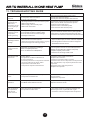
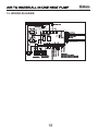
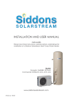
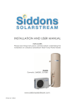
AIR TO WATER
ALL IN ONE HEAT PUMP
Owner’s Manual
Installation and Warranty
http://www.siddonssolarstream.com
CODE: MK3045-16
SIDDONS SOLARSTREAM Pty Ltd
AIR TO WATER ALL IN ONE HEAT PUMP
Contents
1. ONE OF THE WORLD'S MOST EFFICIENT WAYS TO HEAT WATER .................... 3
2. FEATURES OF YOUR SOLARSTREAM.............................................................. 3
2.1 Storage Tank.............................................................................................. 3
2.2 Heat Exchanger.......................................................................................... 3
2.3 Centrifugal Fan.......................................................................................... 3
2.4 Installation Overview................................................................................. 4
2.5 Dynamic Cycle Flow Heating System.......................................................... 4
2.6 Model Nomenclature ................................................................................. 4
3. SPECIFICATIONS & DIMENSIONS .................................................................... 5
3.1 Technical parameters for the main unit ................................................. 5
3.2 Main unit appearance and mounting dimension ..................................... 6
4. INSTALLATION DETAILS.................................................................................. 6
4.1 General Installation Requirements............................................................. 6
4.2 Air Flow...................................................................................................... 6
4.3 Evaporator Drain........................................................................................ 6
4.4 Pressure & Temperature Relief Valve (PTR)................................................ 7
4.5 Expansion Control Valve (ECV) .................................................................. 7
4.6 Cold Water Connection.............................................................................. 7
4.7 Pressure Limiting Valve...........................................................................
8
4.8 Refrigerant R134a...................................................................................... 8
4.9 Draining the Tank....................................................................................... 8
4.10 Hot Water Connection .............................................................................. 8
4.11 Tempering Valves..................................................................................... 8
4.12 Electrical Connection .............................................................................. 8
4.13 Caution Regarding Drilling into the Casing............................................... 9
5. OPERATING INSTRUCTIONS........................................................................... 9
5.1 Filling The Water Heater............................................................................. 9
5.2 Air Expelling Of The Circulating Water Pump.............................................. 9
5.3 Water Quality............................................................................................. 9
5.4 Water Quality Limits - Warranty Exclusion.................................................. 9
6: SAFETY INFORMATION...................................................................................10
1
AIR TO WATER ALL IN ONE HEAT PUMP
Contents
7. MAINTENANCE & SERVICE INFORMATION................................................. 10
7.1 Heating Time............................................................................................. 10
7.2 Air Evaporator Coils.................................................................................. 10
7.3 PTR valve maintenance............................................................................. 10
7.4 Adding an Expansion Control Valve (ECV)................................................. 10
7.5 Thermal Overload (Incorporated into the Digital Controller)....................... 11
7.6 Flushing the Water Storage Tank .............................................................. 11
8. OPERATION & ADJUSTMENT OF THE DIGITAL CONTROLLER..................... 11
8.1 Mounting and fixing method of the remote controller ............................ 12
8.2 Functional illustration of the digital controller.......................................... 12
8.3 Uses of the digital controller.................................................................................. 12
8.4 Operational data setting........................................................................... 14
9. RECOGNITION OF ABNORMAL OPERATION................................................ 15
9.1 Start Up Delay........................................................................................... 15
9.2 Continuous Trickle........................................................................... 15
9.3 Steady Flow............................................................................................. 15
9.4 No Hot Water............................................................................................. 15
10. SYSTEM SIGNAL LIGHTS ................................. ............................................... 16
11. TROUBLE SHOOTING GUIDE..................................................................... 17
12. WIRING DIAGRAM ....................................................................................... 18
13. Warranty Policy ........................................................................................ 19
13.1 Warranty Terms....................................................................................... 19
13.2 Warranty Conditions............................................................................... 19
13.3 Exclusions ............................................................................................. 20
13.4 How to make a warranty claim.................................................................. 20
13.5 Water Filters............................................................................................ 20
13.6 Australian Consumer Law....................................................................... 20
2
AIR TO WATER ALL IN ONE HEAT PUMP
1. ONE OF THE WORLD'S MOST EFFICIENT WAYS TO HEAT WATER
C ongratulations for purchasing a Siddons Solarstream Macon energy efficient Heat Pump Water
Heater, designed for Australian conditions, to produce low energy hot water for many years. In simple
terms, this water heater typically uses just one quarter of the energy of a conventional electric
element water heater by absorbing heat from the surrounding air of between -5 and 45 degrees C,
night and day. It works in hail, rain and shine and becomes more efficient as the air temperature and
humidity rise. It works very well in all types of weather, from a tropical monsoonal down pour to a Southerly
winter gale. You can expect 20-30% greater efficiency per 10 degree rise in the ambient air temperature.
Siddons Solarstream Pty Ltd, with its partners, designs and manufactures energy efficient Heat Pump
Water Heaters for global markets. The Siddons Solarstream Macon range are all-in-one heat pumps
in a compact design with heat pump and water storage tank integrated. A breakthrough technology is
used based upon a dynamic cycle flow heating system that uses just 1 kW/h of electrical energy to
produce up to 3.6 kW/h of heat energy into the water at 20 degrees C ambient air temperature.
By installing a Solarstream, you are assisting the reduction of global greenhouse gas emissions because
a conventional electric element water heater typically consumes about one third of a household's power
usage. In fact, if you want your water heater to become completely carbon neutral, then also install a
3kW per day electricity generating system (for a typical family of 4 people).
As the name implies, an air to water Heat Pump Water Heater is a machine that pumps or transfers heat
absorbed from the ambient air into the water. Even at - 5 degrees C, there is enough heat in the air to
boil the liquid refrigerant into a gas. Once in the form of a gas, it is compressed to superheat the gas up
to 95 degrees C and this heat is then pumped into the water via the dynamic cycle heat exchanger to
deliver hot water very efficiently.
Solarstream is not just for domestic dwellings, it can also be used for factories, schools, hotels, motels,
restaurants, hospitals, laundries, etc.
2. FEATURES OF YOUR SOLARSTREAM
2.1 Storage tank
Solarstream uses a high quality, marine grade (316) stainless steel storage tank as standard.
2.2 Heat Exchanger
The heat exchanger is an efficient, double skinned, tube in tube design. A quality Grundfos
circulating pump is used to cycle all of the tank water through the heat exchanger. All components
of the heat pump come from the best global suppliers.
2.3 Centrifugal Fan
Solarstream uses a centrifugal fan instead of a traditional fan blade, making it one of the smoothest,
most efficient and quietest Heat Pump Water Heaters on the market. The centrifugal fan draws
greater air flow through the evaporator, improving the liquid to gas, phase change of the refrigerant.
This in turn helps raise the coefficient of performance reducing operating time and cost.
3
AIR TO WATER ALL IN ONE HEAT PUMP
2.4 Installation overview
To install your Solarstream, site the unit vertically without leaning on a concrete plinth and ensure it will remain
in a vertical position throughout its usable life and not lean over due to possible erosion of soil under the plinth,
or such risk. Adhere to the relevant plumbing regulations in regard to the water heater installation. We
recommend fixing the tank to the adjacent wall as an added safety precaution. Use only quality plumbing
components such as those supplied in the Siddons QIK kit. Connect the water supply.
Refer Section 4 for details.
Plug in the 15 Amp power lead to a 15 Amp outlet or ask your electrician to hard wire into an off peak or Smart
meter.
2.5 Dynamic cycle flow heating system
Your Solarstream has a dynamic cycle flow heating system that systematically cycles all of the tank water through
the heat exchanger to leave no cold spots so that all of the hot tank water can be delivered. The superheated
compressed gas circulates through a double layered, outside coil whilst the tank water circulates through an inside
coil. The heat from the outside coil is transferred to the inside coil then circulated back into the tank. New cold water
is extracted from the bottom of the tank then cycled dynamically through the heat exchanger until the controller picks
up the signal from the tank sensor to stop heating. The advantages of this method are: heating efficiency, stable hot
water without over heating the top or under heating at the bottom of the tank , and all of the tank water will be heated.
High temperature
Compressor
Hot water
Hydrothermal
exchanger
Outdoor air intake Air exchanger
Water tank
Low
temperature
Cold water
Expansion
valve
2.6 Model Nomenclature
MA HR W S
- ***- Z A B - 270 (**)
Source medium
MA: Air source
MW: Ground source
Design alternative serial number
Tank capacity
270:270L
Function of the unit
HR:heating
A: coil heating
B: circulating heating
A: Horizontal fan direction
B: Upward fan direction
C:Double air duct type
Energy exchange medium
A: Refrigerant
W: Water
S:with solar
(Without solar omitted)
Z: Integrated type
W: Split type(indoor unit )
The figure represents the horse power of unit
eg:010 means 1 horse power
4
AIR TO WATER ALL IN ONE HEAT PUMP
3. SPECIFICATIONS & DIMENSIONS
3.1 Technical parameters for the main unit
Model
MAHRW
010ZAB-270(01) 010ZAB-340(01) S010ZAB-270(01) S010ZAB-340(01)
W
4100
4100
4100
4100
BTU/h
14000
14000
14000
14000
Input power
W
1150
1150
1150
1150
Rated Current
A
5.2
5.2
5.2
5.2
Max.Current
A
6.5
6.5
6.5
6.5
Compressor starting current
A
30
30
30
30
Auxiliary electric heating input power
W
1500~3000
1500~3000
installable
installable
Rated heating capacity
Solar
Power supply
V/PH/Hz
220V~240V/1PH/50Hz
24.7 cc/rev. Rotary
Compressor
Max. Pressure of heat exchanger
MPa
2.8
2.8
2.8
2.8
PTR valve setting
MPa
0.85
0.85
0.85
0.85
Suction pressure
MPa
0.15
0.15
0.15
0.15
Discharge pressure
MPa
2.74
2.74
2.74
2.74
IPX4
IPX4
IPX4
IPX4
L
270
340
270
340
L/h
85
85
85
85
Waterproof degree
Water tank volume
Rated of hot water production
3
Water flow volume
m /h
2.5
2.5
2.5
2.5
Max. working pressure
MPa
0.85
0.85
0.85
0.85
Rated water outlet temperature
¡
60
60
60
60
Max. Water outlet temperature
¡
70
70
70
70
Input/Output connection
inch
3/4
3/4
3/4
3/4
Safety valve connection
inch
3/4
3/4
3/4
3/4
Pressure & Temperature Relief Valve(PTR)
inch
1/2
1/2
1/2
1/2
dB(A)
50
50
50
50
Noise
R134A
Refrigerant gas type
Operating temperature range
Net dimension
Shipping dimension
-5~+45 deg C -5~+45 deg C -5~+45 deg C -5~+45 deg C
W/H(mm)
700x1625
700x1805
700x1625
700x1805
L/W/H(mm) 735/735/1630 735/735/1840 735/735/1630 735/735/1840
Net weight
kg
100
106
101
107
Gross weight
kg
108
116
109
117
Remarks: The technical parameters in this Manual are measured in the following working conditions:
outdoor dry bulb temperature 7 deg C; wet-bulb temperature 6 deg C; water inlet temperature
20 deg C and water outlet temperature 60 deg C.
5
AIR TO WATER ALL IN ONE HEAT PUMP
3.2 Main unit appearance and mounting dimension
A
A
SIDDONS
SIDDONS
B
C
B
C
1090mm
880mm
30mm
Type
A
B
C
MAHRW010ZAB-270(01)
¦700
1595
1105
MAHRW010ZAB-340(01)
¦700
1775
1315
MAHRWS010ZAB-270(01)
¦700
1595
1105
MAHRWS010ZAB-340(01)
¦700
1775
1315
30mm
4 INSTALLATION DETAILS
4.1 General Installation Requirements
This water heater must be installed by a licensed trades person in accordance with:
1) AS 3500.4, National Plumbing and Drainage Code, Part 4: Hot Water Supply Systems
2) AS 3500.4.2, National Plumbing and Drainage Code, Part 4.2: Hot Water Supply Systems
Acceptable Solutions
3) Other relevant Australian Standards, Industry or Local Water Supply regulations or codes for
mains pressure storage tanks
Note: This water heater is not suitable for pool heating or space heating
Corrosion Protection
Fittings to the casing in contact with water must be galvanically compatible. Sealants and / or
Teflon plumbing tape should be used on potentially galvanically incompatible fittings. This is to
protect against possible electrolytic corrosion between the metals where moisture penetration
could occur due to incorrectly or poorly sealed fittings.
4.2 Air Flow
The heat pump extracts heat from air, drawn through the Fin Coil. This produces cold exhaust air
as the heat from the air is absorbed into the refrigerant. In order for your Solarstream to operate
efficiently, good ventilation for the air inlet of the evaporator is required with the warmest possible
air. The cold exhaust air should not be allowed to feed back into the inlet or operational efficiency
will be reduced. The heat pump is therefore best located externally, in a well vented location and
not facing into a prevailing wind. However, alternate locations can be used such as a large double
garage (minimum of 120 cubic metres) or underneath a house as long as there is large air volume.
4.3 Evaporator Drain
During operation, considerable amounts of condensate water will flow from the evaporator drain.
If allowed to simply flow out of the outlet, this water may pool below the unit and can cause
problems to both the water heater and area around it. The evaporator drain should be properly
drained using a length of hose or pipe but must not be connected directly to the PTR valve or
expansion valve drain.
6
AIR TO WATER ALL IN ONE HEAT PUMP
4.4 Pressure and Temperature Relief Valve (PTR)
The Pressure and Temperature Relief valve supplied with the unit is rated at 850 kPa pressure
and must be fitted to the top front socket and made accessible so that the release mechanism can
be operated and, if required, replaced. The outlet of the PTR valve must be suitably drained to
remove the water discharged during the normal heating cycle. The valve thread is G1/2/20mm.
WARNING: A separate drain line must be run for this relief valve. It is not permitted to couple the
drain lines from the relief valve and evaporator into a single common line. The use of a tundish
under the evaporator drain is acceptable with this then connected to the drain of the PTR valve.
MAINTENANCE FOLLOWING INSTALLATION : The PTR valve lever must be operated AT
LEAST ONCE PER YEAR to ensure that the water-ways are clear and to remove naturally
occurring mineral deposits that may adhere to the valve, causing it to leak or rendering it
inoperative. When manually operating the lever, 60 deg C hot water will discharge so be careful
not to touch the PTR water outlet to avoid scalding. BEFORE operating the lever, check to see if
a discharge line is connected to this valve directing the flow of hot water from the valve to a drain.
If no water flows, the PTR valve is defective. TURN OFF THE WATER HEATER AND CALL A
PLUMBER IMMEDIATELY. This PTR valve is designed for safety to relieve pressure.
IMPORTANT: CHECK LOCAL INSTALLATION REQUIREMENTS
4.5 Expansion Control Valve (ECV)
An Expansion Control Valve (ECV) must be fitted in WA, SA, NT and most country areas. Check
with your Plumber. This type of water is referred to as hard or scaling water because calcium
carbonate is deposited out of the water onto any hot metallic surface. The ECV should be set at
700kPa, 150 kPa lower than the PTR valve. The ECV should be fitted onto the cold water supply
line between the non-return valve and the water storage tank. We recommend the installation of
an ECV, even if it is not required, for additional safety and to reduce PTR valve hot water wastage.
4.6 Cold Water Connection
Between the water supply main and the G3/4/25mm socket connection to the storage tank inlet
in the water heater, you must fit an approved Pressure Limiting Valve set at 500kPa water
pressure, an isolating valve, a non-return valve, a line strainer (optional but recommended), and
a union fitting. All fittings must be approved by the relevant Authority as per the following diagram.
Single Line
Power Cable
>150mm
Water
Connections
Non Return Valve
Line Strainer
Isolating Valve
>300mm
Cold Water Inlet
>500mm
Pressure Limiting Valve
PTR Valve
PTR Valve
Expansion Control Valve(If Required)
Drain
Hot Water Outlet
Single Line
Power Cable
SIDDONS
>500mm
Sacrificial anode
(Magnesium)
Water
Connections
Not required for
stainless steel
storage tanks
>300mm
tank temp.
>500mm
PTR Valve
Drain
>500mm
7
AIR TO WATER ALL IN ONE HEAT PUMP
4.7 Pressure Limiting Valve
Your Solarstream is designed for direct connection to a maximum water supply pressure of
500kpa. A Pressure Limiting Valve (complying with AS1357) set at 500 kPa must be fitted
to the cold-water supply line or you will void your warranty. (Refer Section 13.2)
This device must be installed after the isolating valve.
4.8 Refrigerant R134a
The R134a refrigerant used in your Solarstream has a boiling point of -26 degrees C so there is
no risk of damage to the heat pump from frost. Performance will be less in sub zero temperatures
but the system will not be damaged by such climatic conditions. R134a is inflammable, has
insignificant ozone depletion potential to the ozone layer, has negligible acidification potential
(acid rain) but does have relatively high global warming potential (GWP = 1430) so it is important
that a qualified refrigeration mechanic undertakes any refrigeration service work required.
4.9 Draining the Tank
Consideration should be given to the possible necessity of draining the tank at some point.
Draining the tank can be achieved by the connection of a hose to the cold water inlet and running
to a suitable drain. It will be necessary to disconnect the hot water outlet or PTR valve to relieve
any partial vacuum created as the water drains.
4.10 Hot Water Connection
The hot water pipe should be connected to the G3/4/ 25mm socket as shown in the Installation
diagram . NOTE: Plugs are supplied with the water heater to plug off the inlet / outlet sockets that
are not required. Ensure that sealing tape is applied to the plugs for a tight, leak proof seal.
4.11 Tempering Valves
A tempering valve may be required to be fitted to the hot water outlet of your Solarstream to
reduce the risk of hot water scalding in the bathrooms. The tempering valve will reduce the
temperature to 50 degrees C as per the plumbing code. We recommend quality, solar rated
tempering valves only. Standard tempering valves may not function correctly over time.
4.12 Electrical Connection
Your Solarstream is designed for single-phase 220/240V A/C supply only. A certified electrician
must carry out all electrical work according to the local supply authority regulations and AS3000.
A 15-amp circuit breaker must be installed at the power supply for the hot water unit. A separate
circuit breaker is recommended for each unit in the case of multiple installations. The power
connection rating is 220-240VAC 50Hz 15A.
It is not recommended to wire the system to an earth leakage circuit breaker. There is lot of
moisture present while in operation and this can lead to nuisance tripping.
Your Solarstream will require an approved, standard 240V 15A On / Off switch or Junction Box
in close proximity to the heater. It may be connected to a Standard Domestic tariff or Off Peak or
Smart Meter connection. If the unit is connected to an Off Peak connection, the minimum power
availability should be at least 6 hours per day.
The fitted power cord is not to be removed. This cord should be connected with the building wiring
in an On / Off switch enclosure or Junction Box. Faulty wiring may void the warranty if damage
has been sustained to the compressor or heat pump from faulty or sub-standard wiring.
DO NOT TURN ON POWER UNLESS THE TANK IS FULL OF WATER
8
AIR TO WATER ALL IN ONE HEAT PUMP
Safety Notes
Note.1: This water heater is fitted with a thermostat and over-temperature power cut-out (both
incorporated into the digital controller). Under no circumstances should the water heater be
operated without both of these devices being in the circuit. Only a qualified technician or the
manufacturer should carry out replacement.
Note.2: If the supply cord is damaged, the technician must replace it in order to avoid hazard.
Caution: The water heater must be filled with water before turning on the electricity
4.13 Caution Regarding Drilling into the Casing
DO NOT DRILL ANY HOLES INTO THE STORAGE TANK CASING. IT MAY CAUSE DAMAGE
OR LEAKAGE TO THE STORAGE WATER TANK INSIDE AND VOID YOUR WARRANTY
5. OPERATING INSTRUCTIONS
5.1 Filling The Water Heater
Open all hot water taps. Open the isolating valve at the cold-water inlet and allow the storage tank
to fill until water flows through the system. Close each hot water tap after the air is expelled from
the inlet water line.
5.2 Expelling Air from the Circulating Water Pump before Powering Up First Time
After the storage tank is full of water, keep all the hot water taps and isolating valve at the cold
water inlet open to let the water flow out for a few minutes, then power up the unit (use the
ON/ OFF button on the digital controller). If the heat pump continues operating for approximately
5 minutes, then it is functioning satisfactorily. Finally, close all the hot water taps.
If the heat pump stops operating within 5 minutes, then air is still likely to be trapped in the water
pipes. Power off the heat pump and open the hot water taps again for a few more minutes to let
the water flow out, then power up the unit again following the above process.
5.3 Water Quality
Your Solarstream has been manufactured to suit the water conditions of Australian reservoirs
fed by mountain water. Australia is the driest continent on Earth and is subject to extended
periods of drought which can cause water supplies to become mineralised. Because the stainless
steel storage tank of your Solarstream does not have a sacrificial anode inside, it is susceptible to
poor water quality and chlorine when heated to 60 degrees C. Please note that harsh water
supplies can have a detrimental effect on your Solarstream and its life expectancy. Also, if you
use a rain water supply for your Solarstream, this can be acidic and require pH balancing for long
life. Our warranty policy provides options for longer warranty and tank life (refer Section 13).
5.4 Water Quality Limits - Warranty Exclusion
NOTE: Your warranty will be void if your inlet water exceeds these limits (Refer Section 13)
Total dissolved solids
Total hardness
Chloride
Magnesium
Sodium
Electrical Conductivity
pH
600 mg/litre or parts per million
200 mg/litre or parts per million
250 mg/litre or parts per million
10 mg/litre or parts per million
150 mg/litre or parts per million
850 μS/cm (micro siemens per centimetre)
Min 6.5 and Max 8.5
Siddons Solarstream recommends the use of Tanamet filters in WA, SA and country areas where
chlorine is added to the water supply, and a pH balancing filter for rain water supply (refer S13.5).
9
AIR TO WATER ALL IN ONE HEAT PUMP
6. SAFETY INFORMATION
WARNING: For safe performance, this water heater is fitted with:
1) Digital Controller
2) Thermostat (connected to the digital controller) to manage water temperature
3) Thermostat (connected to the digital controller) to manage compressor temperature
4) Non self-setting thermal cut out switch (incorporated into the digital controller)
5) Pressure & Temperature Relief valve
These devices must not be tampered with or removed. The water heater must not be operated
unless each of these devices is fitted and in working order.
This appliance is not intended for use by persons (including children) with reduced physical,
sensory or mental capabilities, or lack of experience and knowledge, unless they have been
given supervision or instruction concerning use of the appliance by a person responsible for their
safety. Children should be supervised to ensure that they do not play with the appliance.
7. MAINTENANCE & SERVICE INFORMATION
Your Solarstream water heater is a completely sealed refrigeration system, similar to a household
refrigerator except that it operates in the opposite direction, heating rather than cooling. The
maintenance program to be used on your Solarstream is not much different to that required for
the maintenance of a refrigerator and a standard electric water heater. NOTE: Before any
electrical components are inspected, your Solarstream MUST be turned off at the power switch.
7.1 Heating time
Your Solarstream should heat all of your tank water in approximately 4 hours depending on the
air temperature and humidity. The reheat time will be less with warmth already in the storage
tank. Get to know the heating characteristics of your Solarstream in your location with your
normal hot water demand. Monitor for any significant change to this, keeping in mind that
Summer time warmer temperatures will enable quicker heat up time.
7.2 Air Evaporator Coils
Solarstream water heaters use evaporator coils to extract heat from the air. The coil is extremely
efficient in warm, humid weather. However, as temperatures drop below 5 degrees C, the coil will
begin to collect ice. The coil has been designed with an auto-defrost mode for such conditions.
The defrost system is automatic and is managed by the digital controller. It is important that the
air inlet vents are kept clean. Restriction of air flow to air-inlet or outlet vents may void your
warranty if the system has been damaged because of insufficient airflow (refer Section 13).
7.3 PTR valve maintenance
Your Pressure & Temperature Relief (PTR) valve is functioning normally if there is some
discharge at the end of each heating cycle. The PTR valve should be checked for adequate
performance or replaced at intervals not exceeding 5 years, or less in areas where there is
mineralised water causing a high incidence of mineral deposits from the hot water. Lifting the
lever on the PTR valve should be done with care at least once per year. If the PTR valve
continues to drip after releasing the lever, there is a possibility that some sediment or grit may
have settled on the valve seat. Try lifting the lever again and carefully releasing it. If the drip
persists, contact your plumber (refer to Section 4.4).
7.4 Adding an Expansion Control Valve (ECV)
In areas with mineralised water causing a high incidence of mineral deposits from the hot water,
an Expansion Control Valve (ECV) should be installed allowing cold water to be released rather
than hot water during the heating cycle. We recommend this to be installed. If in doubt, check
with your plumber; refer to Section 4.5.
10
AIR TO WATER ALL IN ONE HEAT PUMP
7.5 Thermal Overload (Incorporated into Digital Controller)
All models are fitted with a digital controller for heat pump management. One function of the
digital controller is to initiate a shut down and lockout if the compressor reaches a temperature
of 105 degrees C. The heat pump will not automatically restart from this. Turning the power off
then back on will perform a re-set operation.
7.6 Flushing of the Water Storage Tank
As with other hot water heater tanks, dissolved solids in the water or scale may accumulate in
the bottom of the water tank forming sludge. This is generally less of a problem with your
Solarstream because no internal elements or burners are used.
However, if sludge does build up, the following procedure can be followed to clean out the tank:
1) Turn Off power to the unit.
2) Turn Off water supply to the unit.
3) Remove the blanking plug (brass fitting) from the unused inlet (normally on the right hand side
for left hand connected tanks). The inlets are at the bottom of the tank about 300mm up from
the base.
4) Remove the blanking plug from the unused hot water outlet (normally on the right hand side
for left hand connected tanks). The outlets are at the top of the tank.
5) Allow the water to drain from tank. Whilst the water is draining, a non-metallic rod may be
inserted through the open cold-water inlet and used to break up any sludge and assist in its
removal.
6) Turn the cold water supply back on whilst the tank is emptying or after the tank has been
drained and continue with mechanical agitation to further assist the removal of the sludge.
8. OPERATION & ADJUSTMENT OF THE DIGITAL CONTROLLER
Caution:
Do not alter the Digital Controller’s programming and settings without authorisation from Siddons
or a qualified technician.
This following section is provided for qualified technicians to assist in servicing, repairs
or trouble shooting.
11
AIR TO WATER ALL IN ONE HEAT PUMP
8.1 Mounting and Fixing Method of the Remote Controller
NOTE: On this model, the Controller is fixed under the lid.
Illustration 2
Illustration 1
Use flat screwdriver to press down the two tabs
Remove the top covering leftwards to disengage
and lift open the face covering.
two top tabs.
Illustration 3
Illustration 4
Put the remote controller in the electrical base
Set the digital screen in the reverse procedure
as shown in Illustration 2 and Illustration 1 to
box and tighten the two screws.
complete the mounting of the remote controller.
8.2 Functional Illustration of the Digital Controller
The electrical base box of the remote controller is of standard dimension(86 x 86mm), and the
fixed hole distance is 60mm. Before interior decoration, it is best to embed the box with
three-core cable into the wall. User interface and use functions are shown in the figure below.
Initialization mode
Operation mode display area
1
2
ELEC
CLOCKTIMER
OUT
1
2
Clock and timing display area
Button control area
Standby mode
IN
Running status and parameter
setting display area
ELEC
CLOCKTIMER
ELEC
CLOCKTIMER
8.3 Uses of the Digital Controller
ON/OFF control
ON/OFF
button. Press this button to power on and off. In the ON mode, the remote controller
displays the operation mode, clock, timer status, water tank bottom temperature and air temperature.
Note: your Solarstream has a power-off memory function. If you re-power the unit after power-off,
the unit will work again automatically to its previous settings. You can use either the digital controller
or the power switch for ON/OFF.
Ambient air
temperature
Water tank
bottom temperature
OUT
C
ELEC
12
C
TIMER
CLOCK
AIR TO WATER ALL IN ONE HEAT PUMP
SET
SET
SET
SET
MIN
ELEC
TIMER
CLOCK
Parameter 0
Domestic hot water tank temperature
Range: 60 to 70 deg C
Default: 60
Adjustable
SET
ELEC
ELEC
TIMER
CLOCK
Parameter 1
Deadband temperature for re-heating
Range: 2 to 15 deg C
Default: 8
Adjustable by technicians
SET
TIMER
CLOCK
Parameter 2
Not applicable on this model
SET
MIN
ELEC
TIMER
CLOCK
Parameter 3
Not applicable on this model
SET
MIN
C
ELEC
TIMER
CLOCK
Parameter 4
Not applicable on this model
SET
ELEC
ELEC
TIMER
CLOCK
Parameter 5
Not applicable on this model
TIMER
CLOCK
Parameter 6
Defrost cycle
Range: 30 to 90 min
Default: 45 min
Adjustable by technicians
SET
SET
ELEC
TIMER
CLOCK
Parameter 7
Enter defrost mode
Range: -30 to 0 deg C
Default: -7
Adjustable by technicians
SET
MIN
C
ELEC
TIMER
CLOCK
Parameter 8
Exit defrost mode
Range: 2 to 30 deg C
Default: 13
Adjustable by technicians
SET
C
ELEC
ELEC
TIMER
CLOCK
Parameter 9
Exit defrost backup mode
Range: 1 to 12 min.
Default: 8 min
Adjustable by technicians
Parameter 10
Not applicable on this model
SET
SET
C
ELEC
TIMER
CLOCK
Parameter 12
Discharge temperature setting
of compressor to close the
solenoid valve
Range: 60 to 80 deg C
Default: 70
Adjustable by technicians
ELEC
TIMER
CLOCK
C
ELEC
TIMER
CLOCK
Parameter 13
Enter over temperature
compressor protection cut-out
Range: 90 to 127 deg C
Default: 105
Adjustable by technicians
13
TIMER
CLOCK
Parameter 14
Exit over temperature
compressor protection cut-out
Range: 60 to 80 deg C
Default: 70
Adjustable by technicians
ELEC
TIMER
CLOCK
Parameter 11
Discharge temperature setting
of compressor to open the
solenoid valve
Range: 70 to 120 deg C
Default: 95 deg C
Adjustable by technicians
AIR TO WATER ALL IN ONE HEAT PUMP
8.4 Operational Data Setting
The unit's operational data can be set using the controller display unit.
Parameters should be set according to the table below.
Parameter
Content description
range
default
Adjust
60- 65
60
Adjustable
2-15
8
Adjusted by technicians
10-90
55
Not applicable
0-90
6(N*5)
Not applicable
60-90
70
Not applicable
0-90 min
30 min
Not applicable
30-90 min
45 min
Adjusted by technicians
0
Domestic hot water tank temperature setting
1
Tank temperature difference value for the
compressor restart setting
2
Start temp. of heating Aux. setting
3
Electric heating start time delay
4
The temp. of start high-temperature
disinfection per week setting
5
High-temperature disinfection maintain time
6
Defrost cycle setting
7
Enter defrost temperature setting
-30-0
-7
Adjusted by technicians
8
Exit defrost temperature setting
2-30
13
Adjusted by technicians
9
Exit defrost max. time cycle setting
1-12 min
8 min
Adjusted by technicians
1~20
6
Not applicable
70-120
95
Adjusted by technicians
60~80
70
Adjusted by technicians
90-127
105
Adjusted by technicians
60~80
70
Adjusted by technicians
10
11
12
13
14
Difference temp. Value between solar
and tank for Solar pump start setting
Discharge temperature setting of
compressor to open the solenoid valve
Discharge temperature setting of
compressor to close the solenoid valve
The enter temperature setting of discharge
temperature over temperature protection
The exit temperature setting of discharge
over temperature protection
A
Tank bottom temperature
-9-99
Actual testing value
B
Tank top temperature
-9-99
Actual testing value
C
Coil temperature
-9-99
Actual testing value
D
Discharge temperature
0-127
Actual testing value
E
Solar collector temperature
-9-99
Not applicable
F
Ambient temperature
-9-99
Actual testing value
Note:
Parameter 3: Every unit means 5 minutes ,for example, if you set the parameter to '1', that is
5 minutes, set it to ‘2', that is 10 minutes, etc.
If you stop adjusting the controller for 10 seconds, it will log out automatically.
14
AIR TO WATER ALL IN ONE HEAT PUMP
9. RECOGNITION OF ABNORMAL OPERATION
9.1 Start up Delay
NOTE: The heat pump has a 3-minute time delay on re-start. If the power to the heat pump is cut
during its heating cycle, then a time delay period will commence upon re-start. The compressor
and fan will not operate until the completion of this delay period.
9.2 Continuous Trickle
If you notice a continuous trickle of water from the PTR valve, this is likely due to a build up of grit
or scale. Lift the lever to release water for a few seconds from the PTR valve. This may dislodge
small particles of foreign matter to rectify the fault. It is normal for the PTR valve to release a
small quantity of water during the heating cycle. The amount of discharge will depend on hot
water usage. As a guide, if it discharges more than 20 litres of water in 24 hours then there may
be a problem (refer Section 4.4 and 7.3).
9.3 Steady Flow
If you notice a steady flow of water from the PTR valve, then this may be caused by excessive
water supply pressure. Note, a 500kPa Pressure Limiting valve must be fitted. It may also be
caused by a faulty Pressure & Temperature Relief (PTR) valve, or a faulty Thermostat / Digital
Controller. Turn off the power and contact a qualified technician or Siddons for help (refer S4.7).
9.4 No Hot Water
1) Check if the power is switched on. Check that the isolating switch, to which your Solarstream
is connected, is switched on. Check that the switch marked “Water Heater” on your power
switchboard is turned on. Check that all circuit breakers have been reset.
If you are connected to Off Peak or a Smart Meter, check that you have power supplied when
checking the operation of your Solarstream.
2) Check that the thermal overload (on the digital controller) has not tripped. Turn the power off
then back on to perform a re-set action.
3) Check whether the Pressure & Temperature Relief valve is discharging too much water
(refer to Section 4.4).
4) Check that you have the correctly sized water heater for your requirements. Sizing details are
available from your plumber or Siddons. The rule of thumb is 30-50 litres per person per day,
more in winter, less in summer.
5) Check your household water usage. Is one outlet (such as the bath) using more hot water than
you think? Review your family's hot water usage and if necessary check the shower flow rates
with a bucket and measure this. Consider installing low volume shower heads and other
measures to reduce hot water usage.
15
AIR TO WATER ALL IN ONE HEAT PUMP
10. SYSTEM SIGNAL LIGHTS
Motherboard
signal lights
Malfunction and
Protection Name
Off
Standby
On
Normal start
PP1
1 flash 1 off
Bottom of water tank
temp. sensor failure
PP2
2 flash 1 off
Not applicable
3 flash 1 off
System coil temp.
sensor failure
PP4
4 flash 1 off
Compressor discharge
temp. sensor failure
PP5
5 flash 1 off
Fault
code
PP3
10 flash 1 off
EE1
6 flash 1 off
System high pressure
protection
EE2
7 flash 1 off protection
EE3
8flash 1 off
EE4
9 flash 1 off over temp. protection
Defrosting
indication
EE8
Check whether the temperature thermistor connection at the
bottom of the tank is loose.
Re-connect the thermistor or replace it.
Check whether the temperature thermistor connection from the
evaporator coil is loose .
Re-connect the thermistor or replace it.
Check whether the compressor discharge temperature thermistor
connection is loose.
Re-connect the thermistor or replace it.
Not applicable
Ambient temp. sensor
failure
PP6
Solution (for technicians)
System low pressure
Check whether ambient temperature thermistor connection is
loose.
Re-connect the thermistor or replace it.
Check for lack of water in the system or air in the cycle flow heating
system and discharge it to prevent over heating the water.
Check if the refrigerant is too high and correct it.
Check if the high pressure switch has been damaged, replace it.
Check for low refrigerant.
Check for damage to the low pressure switch, replace it.
Not applicable
Compressor discharge Check for lack of water in the system or air in the cycle flow heating
system and discharge it to prevent over heating the water.
or water temp. too high Check for loss of refrigerant in the system.
Continuous
flashing
System is running in defrost mode.
No flashing Communication failure Communication wires disconnected or connection failure.
16
AIR TO WATER ALL IN ONE HEAT PUMP
11. TROUBLESHOOTING GUIDE
Malfunction
Reason
Solution
1.Turn off power and inspect power supply
2.Identify the cause and rectify
3.Identify the cause and replace with new fuse
Unit does
not work
1.Power failure
2.Loose power wire connection
3.Fuse of controller blown
The pump is
operating, but
water isn't
circulatory or the
noise of pump is
too loud
1.Shortage of water or air in the water system 1.Check water supply equipment and replenish
water, remove the air from the water system
2.Water pump damage
2.Change over the water pump
3.Water supply valve not fully open
3.Open the valve of the water system
4.Water filter is blocked
4.Clean the water filter and the pump
Unit heating
capacity is low or
compressor
working too long
1.Shortage of refrigerant or leakage
2.Poor thermal insulation of water system
3.Poor air flow into the air heat exchanger
4.Shortage of water flow
Compressor
discharge pressure
too high
1. Water pump is not working
2. There is air in the water system
3. Excessive refrigerant (from repair / re-gas)
4.Heat exchanger not working properly
1. Check / fix power supply to the water pump
2. Open hot water taps, run water until all air expelled
3. Call refrigeration mechanic to reduce refrigerant
4. Call Siddons Service Centre
Compressor
suction pressure
too low
1.Shortage of refrigerant or leakage
2.Filter or capillary blocked
3.Poor condenser heat dissipation
1. Call refrigeration mechanic to c heck the system for
leakage, fix the leak and re-gas the heat pump
2.Replace capillary tube or filter
3.Clean the fin coil using a water hose
Compressor will
not turn on
1.Power failure
2.Compressor contactor malfunctions
3.Loose connection
4.Overload protection of compressor activates
5.Incorrect setting of the return water
temperature in the water tank
6.Compressor capacitor malfunctions
1.Check the power supply and restore
2.Replace the contactor
3.Check for loose wires and re-connect
4.Check that the current / Amp draw of compressor is
within specification, may require replacement of the
compressor
5.Reset the return water temperature
6.Replace the capacitor
Loud compressor
noise
1.Liquid refrigerant enters the compressor
2.Compressor breaks down
1.Check the cause for flooding of the compressor and
solve the problem
2.Replace the compressor
Blower is out of
operation
1.The relay or capacitor of the blower breaks down
2.The Blower motor seizes or burns out
1.Replace the blower relay or capacitor
2.Replace the blower motor
The compressor
is in operation
but the unit
does not heat
1.The refrigerant has leaked out
2.Compressor breaks down
1.Check the system for leakage, fix leak and re-gas
2.Improve thermal insulation of the system pipeline
3.Clean the fin coil with water and improve air flow
4.Check the line strainer on the water inlet and clean it
1.Check the system for refrigerant leakage and
tell tale signs of oil, repair leak and re-gas
2. Check the reason and replace the compressor
17
AIR TO WATER ALL IN ONE HEAT PUMP
12. WIRING DIAGRAM
Water cycle Pump
Solenoid valve
Fan
Red
Y/G
Compressor Electrical
heating
Solar collector temp.(5K resistor) 1
Discharge temp.
Coil temp.
White
Red C Y/G
R
COM S
Blue
Blue
Capacitance
Ambient temp.
Run indicator
Black
Blue
Brown
Blue
Four-way valve
Top of tank temp.(5K resistor)
Bottom of tank temp.
18
Blue
Red
Turn on/off
3
Wire controller
Solar water cycle
pump power output
High pressure switch
Power input
Over heating protection
Blue
Transformer
Low pressure switch
Blue
Brown Blue Yellow
Self-check key
Blue
Capacitance
Annotation:
1 :Effective for Solar model
2 :Effective for electric heating model
3 :Effective for electric heating model
2
13. WARRANTY POLICY
13.1 Warranty Terms
Cover Period
The following warranty policy for your Solarstream Heat Pump Water Heater applies from the
date of despatch from Siddons. The warranty for the various components of your Solarstream is
set out below.
NOTE: In the Warranty Policy below, we define PURE WATER as coming from reservoirs
supplied by mountain water including the Great Dividing Range and Tasmania. We define
MINERALISED WATER as applying to the States of WA and SA, the Territory of NT and country
areas with their water supply away from mountain sourced water including dams, rivers,
springs, bores and other natural ground sources.
Refer Section 5.4 for Water Quality Limits which apply to this Warranty Policy.
10 years warranty on the water storage tank with PURE WATER supply (refer section 5.4)
8 years warranty on the water storage tank in MINERALISED WATER but still within our Water
Quality Limits stated in Section 5.4 PROVIDED THAT a Tanamet Crystal water filter is installed
into the water inlet line. Otherwise 3 years warranty (refer Section 13.5 below).
8 years warranty on the water storage tank for RAIN WATER supply within our Water Quality Limits
stated in Section 5.4 PROVIDED THAT a pH balancing filter is installed into the water tank inlet line
to reduce the acidity of the rain water. Otherwise 3 years warranty(refer Section 13.5 below).
3 years warranty on all parts
1 year warranty on Labour for all warranty claims with a travel allowance limited to two hours,
labour only, and only for legitimate claims relating to your Solarstream Heat Pump Water Heater.
13.2 Warranty Conditions
1. Your Solarstream is installed by a licensed plumber or authorised technician in accordance
with the above installation instructions.
2. All relevant statutory requirements applicable to the installation are observed.
3. Your Solarstream must be installed, operated and maintained in accordance with instructions
supplied in this Owner’s Manual.
4. The warranty only applies to your Solarstream and does not apply to any additional
modifications not specifically endorsed by Siddons nor any electrical or plumbing parts supplied
by your installer.
5. The system is covered for the indicated period from the date of delivery from Siddons.
6. Should your Solarstream be replaced in part or whole during the warranty period, only the
balance of the original warranty will continue to be effective.
7. Proof of purchase or warranty registration may be required to validate your warranty claim. We
recommend online registration of your Solarstream at www.siddonssolarstream.com after
installation for warranty purposes.
8. Your Solarstream is used only for its intended purpose.
9. Should your water supply require regular flushing to clear sediment build-up, then the drain
cock for flushing must be fitted at the time of installation (consult your plumber).
10. Regarding a site investigation for warranty purposes, travel is limited to two hours maximum,
time only, for the first year and only for legitimate claims relating to your Solarstream.
11. Siddons is excluded to the extent allowable by law from responsibility for any consequential
loss including: injury to persons, injury to property, economic loss, pain and suffering or legal or
other damages flowing from any manufacturing fault/defect.
12. The Heat Pump may operate in weather conditions lying within the range of -5ºC cold weather
and 45ºC hot weather temperature. Operation outside of this range may void your warranty.
13. A Pressure Limiting Valve must be installed in the water inlet line and set to 500kPa (refer
Section 4.7).
19
13.3 Exclusions
The following warranty exclusions may cause your Solarstream warranty to become void, and
which may incur a service charge and cost for parts should this become necessary:
1. Where service is required to reconnect the operation of the Solarstream due to problems
related with abnormal water supply such as high water pressure, faulty plumbing and/or
electrical wiring, or major variations in electricity supply;
2. Where the system fails due to misuse, accidental damage, flood, acts of God, incorrect
installation or unlicensed service repair work attempts;
3. Where water stored in the tank is MINERALISED WATER beyond our water quality limits set
out in Section 5.4 (eg from sources such as a spring, bore, river, other natural ground sources,
or excessively acidic water from a rain water supply);
4. Where there are claims for damage to wall foundations (outside), furnishings (inside), rooves
or other losses, directly or indirectly due to leakage of water from your Solarstream;
5. Where damage or breakage is not covered by this warranty, and should be added separately
to your general household insurance policy;
6. Where the claim is due to an extraneous cause beyond the normal operation and fair wear and
tear of the heat pump, including: blocking the air inlet or outlet, leaking water pipes, defective PTR
valve causing continual dripping or running water for more than 3 months, etc; and
7. Where benefits conferred by this warranty are additional to other rights and remedies in
respect of this product, which the purchaser has under relevant Australian Laws.
13.4 How to Make a warranty Claim
We recommend online registration of your Solarstream at www.siddonssolarstream.com after
installation to assist processing of any warranty claims. Alternately, you can post your
registration details to us. When making a warranty claim, you will need to quote your serial
number, model number, installation date and owner details. We will advise the process to
investigate and resolve your issue.
13.5 Water Filters
Tanamet XD50 crystal water filters provide a slowly dissolving "glassy" polyphosphate into the
waterspecifically designed for domestic hot water systems using MINERALISED WATER. The
crystals are applied by means of a cartridge placed in a filter housing installed into the water
supply inlet before entering the hot water storage tank. The crystals dissolve very slowly at the
rate of a few parts per million into the inlet water flow to prevent scale formation and corrosion.
They soften hard water, reduce scaling, reduce corrosion, reduce copper staining, stabilise
dissolved iron (red water) and stabilise manganese. The Tanamet XD50 filter has a life of
approximately 8 years after which time you must replace the filter to maintain storage tank life
when the crystals finally dissolve. Other similar crystal water treatment systems dissolve much
more quickly which is why we recommend Tanamet XD50 crystals, available from Siddons.
Tanamet XD50 crystals do not have any adverse effect on the quality of water consumption for
humans and as at 2013 their use has been approved by Water Authorities in Australia and France.
Limestone water filters raise the pH of rainwater from between 5.5 and 6.0 to above 6.5.This is
due to carbon dioxide that's dissolved in the atmosphere and with pollution in the air it can become
even more acidic (eg Europe has a significant acid rain problem). Neutral pH is 7.0. Our warranty
conditions state 6.5 to 8.5 so you MUST TAKE ACTION TO RAISE THE ALKALINITY OF YOUR
RAIN WATER SUPPLY. Siddons recommends applying limestone to your rain water supply by
means of a cartridge placed in a filter housing installed into the water supply inlet before entering
the hot water storage tank. Contact your Dealer or Siddons to purchase a limestone filter. You will
be able to monitor the slow dissolving limestone and you must replace the filter to maintain
storage tank life when the limestone finally dissolves.
13.6 Australian Consumer Law
In addition to this warranty policy, you also have rights and remedies under the Australian
Consumer Law including replacement or refund for a major failure or repair for a minor failure.
20