1
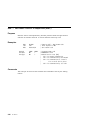
PC DOS 7 Technical Update
Document Number GG24-4459-00
February 1995
International Technical Support Organization
Boca Raton Center
Take Note!
Before using this information and the product it supports, be sure to read the
general information under “Special Notices” on page xiii.
First Edition (February 1995)
This edition applies to PC DOS Version 7.
Order publications through your IBM representative or the IBM branch office serving
your locality. Publications are not stocked at the address given below.
An ITSO Technical Bulletin Evaluation Form for reader′s feedback appears facing
Chapter 1. If the form has been removed, comments may be addressed to:
IBM Corporation, International Technical Support Organization
Dept. 91J Building 235-2 Internal Zip 4423
901 NW 51st Street
Boca Raton, Florida 33431-1328
When you send information to IBM, you grant IBM a non-exclusive right to use or
distribute the information in any way it believes appropriate without incurring any
obligation to you.
Copyright International Business Machines Corporation 1995. All rights reserved.
Note to U.S. Government Users — Documentation related to restricted rights — Use,
duplication or disclosure is subject to restrictions set forth in GSA ADP Schedule
Contract with IBM Corp.
Abstract
IBM PC DOS 7 has been designed for all types of users who need an efficient
single tasking personal computer operating system. It incorporates many
new utilities such as anti-virus software, comprehensive backup programs,
PCMCIA support and DOS Pen extensions. Also incorporated are new
features to enhance the available memory and disk space.
This book is a technical reference, upgraded from IBM DOS 5.02 and written
for DOS programmers, who develop applications for IBM Personal
Computers or compatible systems.
The program developer should be competent on the IBM Personal Computer
and/or the Personal System/2 and should be familiar with DOS and at least
one personal computer programming language.
(381 pages)
Copyright IBM Corp. 1995
iii
iv
PC DOS 7
Contents
Abstract
. . . . . . . . . . . . . . . . . . . . . . . . . . . . . . . . . . . . . . . .
Special Notices
. . . . . . . . . . . . . . . . . . . . . . . . . . . . . . . . . . .
Preface
. . . . . . . . . . . . . . . . . . . . . . . . . . . . . .
. . . . . . . . . . . . . .
How This Document is Organized
. . . . . . . . . . . . . . . . . . . . . .
Related Publications
International Technical Support Organization Publications
. . . . . . . . .
. . . . . . . . .
. . . . . . . . .
. . . . . . . . .
Chapter 1. Introduction . . . . . . . . . . . . . . . . . . . . . . . . . . . . .
. . . . . . . . . . . . . . . . . . . . . . . . . . .
What′s New for PC DOS 7
New, Changed or Removed PC DOS Commands and Device Drivers
. . . . . . . . . . . . . . .
New, Changed or Removed Optional Tools
New, Changed or Removed .INI Files . . . . . . . . . . . . . . . . . . .
. .
New, Changed or Removed Keyboard Layouts and Code Pages
. . . . . . . . . . . . . . . . . . . . . .
Minimum Hardware Configuration
Chapter 2. Accessing Disks . . . . . . . . . .
The Disk Format . . . . . . . . . . . . . . . . .
. . . . . . . . . . . . . . .
The Boot Record
. . . . . .
The File Allocation Table (FAT)
. . . . . . . . . . . . . .
The Disk Directory
The Data Area . . . . . . . . . . . . . . . . .
. . . . . . . . . . . . . . .
Accessing the Disk
. . .
Requesting Drive and Disk Information
Reading and Writing Data Directly to the Disk
. .
. .
. .
. .
. .
. .
. . . . . . . . . . . . . . . . . .
. . . . . . . . . . . . . . . . . .
. . . . . . . . . . . . . . . . . .
. . . . . . . . . . . . . . . . .
. . . . . . . . . . . . . . . . .
. . . . . . . . . . . . . . . . .
. . . . . . . . . . . . . . . . .
. . . . . . . . . . . . . . . . .
. . . . . . . . . . . . . . . .
Chapter 3. Accessing Files with File Handles
. . . . . . . . .
Filenames . . . . . . . . . . . . . . . . . . . . . . . . . . . . . . .
File Handles . . . . . . . . . . . . . . . . . . . . . . . . . . . .
Special File Handles . . . . . . . . . . . . . . . . . . . . . . .
Reading and Writing Data to a File . . . . . . . . . . . . . . . .
Requesting and Specifying File Attributes . . . . . . . . . . . .
. . . . . . . . . . . . . . . . . . . . .
Accessing Subdirectories
Accessing Directories . . . . . . . . . . . . . . . . . . . . . . . .
Finding Files in Directories . . . . . . . . . . . . . . . . . . . . .
Requesting and Specifying National Language Support (NLS)
Controlling Network Operations . . . . . . . . . . . . . . . . . .
Chapter 4. Accessing Files Using File Control Blocks
The File Control Block (FCB) . . . . . . . . . . . . . . .
Copyright IBM Corp. 1995
. .
. . . . . . .
. . . . . . .
. . . . . . .
. . . . . . .
. . . . . . .
. . . . . . .
. . . . . . .
. . . . . . .
. . . . . . .
. . . . . . .
. . . . . . .
. . . . . . . . . . .
. . . . . . . . . . . .
iii
xiii
xv
xv
xvi
xvi
1
1
2
4
5
5
5
7
7
7
10
11
12
12
12
13
15
15
16
16
17
17
17
20
21
21
21
23
23
v
The Extended FCB
. . . . . .
The Disk Transfer Area (DTA)
. . . . . . . . .
Accessing Files
Accessing Sequential Records
Accessing Random Records . .
Finding Files in Directories . . .
. . . . . . . . . . . . . . . . . . . . . . . . .
. . . . . . . . . . . . . . . . . . . . . . . .
. . . . . . . . . . . . . . . . . . . . . . . . .
. . . . . . . . . . . . . . . . . . . . . . . . .
. . . . . . . . . . . . . . . . . . . . . . . . .
. . . . . . . . . . . . . . . . . . . . . . . . .
Chapter 5. Managing Device I/O . . . . . . . . . . . . . .
Managing Display I/O . . . . . . . . . . . . . . . . . . . . .
. . . . . . . . . . . . . . . . . . .
Managing Keyboard I/O
. . . . . . . . . . . . . . . .
Managing Miscellaneous I/O
. . . . . . . . . . . . . .
Managing File System Activities
Accessing the System Device Drivers′ Control Channel
Reading and Writing Data in Binary and ASCII Modes
Chapter 6. Controlling Processes
. . . . . . . . . . .
. . . . . . . . . . . . . . . . . . . .
Allocating Memory
. . . . . . . . . .
PC DOS 7 Memory Management
. . . . . . . . . . . . .
The PC DOS 7 Memory Map
. . . . . . . . . .
Identifying a Program at Load Time
The Program Segment . . . . . . . . . . . . . . . . .
. . . . . . . . . . . .
Loading and Executing Overlays
. . . . . . . . . . . . . . . . .
The Parameter Block
Terminating a Program/Subprogram . . . . . . . . . .
Loading an Overlay without Executing It . . . . . . . .
. . . . . . . . . . . . .
Calling a Command Processor
Responding to Errors . . . . . . . . . . . . . . . . . . .
Responding to a Control-Break Action . . . . . . . . .
Requesting and Specifying the System Date and Time
Requesting and Specifying the Interrupt Vectors . . .
Chapter 7. Debugging a Program
. . . .
The DEBUG Utility . . . . . . . . . . . . . .
Starting the DEBUG.COM Program . . . .
Entering Commands at the DEBUG Prompt
DEBUG Command Summary . . . . . .
The DEBUG Work Space . . . . . . . . . .
A (Assemble) Command . . . . . . . . . .
. . . . . . . . . .
C (Compare) Command
D (Dump) Command . . . . . . . . . . . . .
E (Enter) Command . . . . . . . . . . . . .
F (Fill) Command . . . . . . . . . . . . . . .
. . . . . . . . . . . . . .
G (Go) Command
H (Hexarithmetic) Command . . . . . . . .
vi
PC DOS 7
. . . . . . . . . .
. . . . . . . . . .
. . . . . . . . . .
. . . . . . . . . .
. . . . . . . . . .
. . . . . . . . . .
. . . . . . . . . .
. . . . . . . . . . . .
. . . . . . . . . . . .
. . . . . . . . . . . .
. . . . . . . . . . . .
. . . . . . . . . . . .
. . . . . . . . . . . .
. . . . . . . . . . . .
. . . . . . . . . . . .
. . . . . . . . . . . .
. . . . . . . . . . . .
. . . . . . . . . . . .
. . . . . . . . . . . .
. . . . . . . . . . . .
. . . . . . . . . . .
. . . . . . . . . . . .
. . . . . . . . . . . . . . . . . . .
. . . . . . . . . . . . . . . . . . .
. . . . . . . . . . . . . . . . . . .
. . . . . . . . . . . . . . . . . .
. . . . . . . . . . . . . . . . . . .
. . . . . . . . . . . . . . . . . . .
. . . . . . . . . . . . . . . . . . .
. . . . . . . . . . . . . . . . . . .
. . . . . . . . . . . . . . . . . . .
. . . . . . . . . . . . . . . . . . .
. . . . . . . . . . . . . . . . . . .
. . . . . . . . . . . . . . . . . . .
. . . . . . . . . . . . . . . . . . .
26
26
27
28
28
28
29
29
29
30
30
31
32
33
33
33
34
36
36
39
39
40
41
41
42
42
44
44
45
45
45
46
47
48
49
51
52
55
57
58
60
I (Input) Command . . . . . . . .
. . . . . . .
L (Load) Command
M (Move) Command . . . . . . .
N (Name) Command . . . . . . .
O (Output) Command . . . . . .
. . . . .
P (Proceed) Command
Q (Quit) Command . . . . . . . .
R (Register) Command . . . . .
S (Search) Command . . . . . .
T (Trace) Command . . . . . . .
U (Unassemble) Command . . .
W (Write) Command . . . . . . .
XA (EMS Allocate) Command .
XD (EMS Deallocate) Command
. . .
XM (EMS Map) Command
. .
XS (EMS Status) Command
. . . .
DEBUG Error Messages
. . . . . . . . . . . . . . . . . . . . . . . . .
. . . . . . . . . . . . . . . . . . . . . . . . .
. . . . . . . . . . . . . . . . . . . . . . . . .
. . . . . . . . . . . . . . . . . . . . . . . . .
. . . . . . . . . . . . . . . . . . . . . . . . .
. . . . . . . . . . . . . . . . . . . . . . . . .
. . . . . . . . . . . . . . . . . . . . . . . . .
. . . . . . . . . . . . . . . . . . . . . . . . .
. . . . . . . . . . . . . . . . . . . . . . . . .
. . . . . . . . . . . . . . . . . . . . . . . . .
. . . . . . . . . . . . . . . . . . . . . . . . .
. . . . . . . . . . . . . . . . . . . . . . . . .
. . . . . . . . . . . . . . . . . . . . . . . . .
. . . . . . . . . . . . . . . . . . . . . . . . .
. . . . . . . . . . . . . . . . . . . . . . . . .
. . . . . . . . . . . . . . . . . . . . . . . . .
. . . . . . . . . . . . . . . . . . . . . . . . .
Chapter 8. Writing an Installable Device Driver
. . . . . . . . . . . . .
Types of Device Drivers
Character Device Drivers . . . . . . . . . . .
Block Device Drivers . . . . . . . . . . . . . .
How PC DOS 7 Installs Device Drivers . . . . .
The Basic Parts of a Device Driver . . . . . . .
. . . . . . . . . .
The Device Driver Header
. . . . . . . . . . . . .
The Strategy Routine
. . . . . . . . . . . . .
The Interrupt Routine
. . . . . . .
How PC DOS 7 Passes a Request
Responding to Requests . . . . . . . . . . . . .
Initialization Request . . . . . . . . . . . . . .
Media Check Request . . . . . . . . . . . . .
Build BPB Request . . . . . . . . . . . . . . .
Input and Output Requests . . . . . . . . . .
. . .
Nondestructive Input No Wait Request
Character Input and Output Status Requests
Character Input and Output Flush Requests
. . . . . . . . . .
Open and Close Requests
Removable Media Request . . . . . . . . . .
Output Until Busy . . . . . . . . . . . . . . . .
Generic IOCTL Request . . . . . . . . . . . .
. . . . . . . . .
Get Logical Device Request
Set Logical Device Request . . . . . . . . . .
. . . . . . . . . . . . . . . . . . .
IOCtl Query
. . . . . . . . . . . . . . .
. . . . . . . . . . . . . . . .
. . . . . . . . . . . . . . . .
. . . . . . . . . . . . . . . .
. . . . . . . . . . . . . . . .
. . . . . . . . . . . . . . . .
. . . . . . . . . . . . . . . .
. . . . . . . . . . . . . . . .
. . . . . . . . . . . . . . . .
. . . . . . . . . . . . . . . .
. . . . . . . . . . . . . . . .
. . . . . . . . . . . . . . . .
. . . . . . . . . . . . . . . .
. . . . . . . . . . . . . . . .
. . . . . . . . . . . . . . . .
. . . . . . . . . . . . . . . .
. . . . . . . . . . . . . . .
. . . . . . . . . . . . . . . .
. . . . . . . . . . . . . . . .
. . . . . . . . . . . . . . . .
. . . . . . . . . . . . . . . .
. . . . . . . . . . . . . . . .
. . . . . . . . . . . . . . . .
. . . . . . . . . . . . . . . .
. . . . . . . . . . . . . . . .
Contents
61
61
64
65
66
67
68
68
71
72
74
76
79
80
80
81
82
85
85
85
85
85
87
87
90
90
90
92
93
94
97
100
101
101
102
102
103
104
104
104
105
105
vii
Appendix A. PC DOS 7 Interrupts
. . . . . .
Interrupt 20H Program Terminate . . . . . . .
Interrupt 21H Function Request . . . . . . . .
Interrupt 22H Terminate Address . . . . . . .
. . . .
Interrupt 23H Ctrl-Break Exit Address
.
Interrupt 24H Critical Error Handler Vector
Interrupt 25H/26H Absolute Disk Read/Write
.
Interrupt 27H Terminate but Stay Resident
Interrupt 28H− 2 EH Reserved for PC DOS 7
. . . . . . .
Interrupt 2FH Multiplex Interrupt
. . . . . . . . . . . . . . . .
DOSDOCK API
APM Error Return Codes and Descriptions
.
Interrupt 30H-3FH Reserved for PC DOS 7
. . . . . . . . . . . . . . . . .
. . . . . . . . . . . . . . . . .
. . . . . . . . . . . . . . . . .
. . . . . . . . . . . . . . . . .
. . . . . . . . . . . . . . . . .
. . . . . . . . . . . . . . . . .
. . . . . . . . . . . . . . . . .
. . . . . . . . . . . . . . . . .
. . . . . . . . . . . . . . . . .
. . . . . . . . . . . . . . . . .
. . . . . . . . . . . . . . . . .
. . . . . . . . . . . . . . . .
. . . . . . . . . . . . . . . . .
Appendix B. PC DOS 7 Function Calls
. . . . . . . . . . . . . .
Using PC DOS 7 Function Calls . . . . . . . . . . . . . . . . . . .
Program Code Fragments . . . . . . . . . . . . . . . . . . . . .
.COM Programs . . . . . . . . . . . . . . . . . . . . . . . . . . .
PC DOS 7 Registers . . . . . . . . . . . . . . . . . . . . . . . . . .
Responding to Errors . . . . . . . . . . . . . . . . . . . . . . . . .
Extended Error Codes . . . . . . . . . . . . . . . . . . . . . . .
. . . . . . . . . . . . . . . . . . . . .
00H — Program Terminate
01H — Console Input with Echo . . . . . . . . . . . . . . . . . . .
. . . . . . . . . . . . . . . . . . . . . . . .
02H — Display Output
03H — Auxiliary Input . . . . . . . . . . . . . . . . . . . . . . . . .
. . . . . . . . . . . . . . . . . . . . . . .
04H — Auxiliary Output
05H — Printer Output . . . . . . . . . . . . . . . . . . . . . . . . .
06H — Direct Console I/O . . . . . . . . . . . . . . . . . . . . . .
. . . . . . . . . . . .
07H — Direct Console Input Without Echo
. . . . . . . . . . . . . . . .
08H — Console Input Without Echo
09H — Display String . . . . . . . . . . . . . . . . . . . . . . . . .
. . . . . . . . . . . . . . . . . .
0AH — Buffered Keyboard Input
0BH — Check Standard Input Status . . . . . . . . . . . . . . . .
0CH — Clear Keyboard Buffer and Invoke a Keyboard Function
0DH — Disk Reset . . . . . . . . . . . . . . . . . . . . . . . . . . .
. . . . . . . . . . . . . . . . . . . . . . . . . .
0EH — Select Disk
. . . . . . . . . . . . . . . . . . . . . . . . . . .
0FH — Open File
. . . . . . . . . . . . . . . . . . . . . . . . . . .
10H — Close File
. . . . . . . . . . . . . . . . . . . .
11H — Search for First Entry
. . . . . . . . . . . . . . . . . . . .
12H — Search for Next Entry
13H — Delete File . . . . . . . . . . . . . . . . . . . . . . . . . . .
. . . . . . . . . . . . . . . . . . . . . . .
14H — Sequential Read
. . . . . . . . . . . . . . . . . . . . . . .
15H — Sequential Write
16H — Create File . . . . . . . . . . . . . . . . . . . . . . . . . . .
viii
PC DOS 7
. . . . . .
. . . . . .
. . . . . .
. . . . . .
. . . . . .
. . . . . .
. . . . . .
. . . . . .
. . . . . .
. . . . . .
. . . . . .
. . . . . .
. . . . . .
. . . . . .
. . . . . .
. . . . . .
. . . . . .
. . . . . .
. . . . . .
. . . . .
. . . . . .
. . . . . .
. . . . . .
. . . . . .
. . . . . .
. . . . . .
. . . . . .
. . . . . .
. . . . . .
. . . . . .
107
107
107
107
108
108
112
114
115
115
118
129
132
133
135
136
136
136
138
138
142
143
144
145
146
147
148
149
150
151
152
153
154
155
156
157
158
159
161
162
163
164
165
17H
19H
1AH
1BH
1CH
1FH
21H
22H
23H
24H
25H
26H
27H
28H
29H
2AH
2BH
2CH
2DH
2EH
2FH
30H
31H
32H
33H
34H
35H
36H
38H
39H
3AH
3BH
3CH
3DH
3EH
3FH
40H
41H
42H
43H
44H
45H
46H
47H
— Rename File . . . . . . . . . . . . . . . . . . . . . .
— Current Disk . . . . . . . . . . . . . . . . . . . . . .
— Set Disk Transfer Address . . . . . . . . . . . . .
— Allocation Table Information . . . . . . . . . . . .
— Allocation Table Information for Specific Device
— Get Default Drive Parameter Block . . . . . . . .
— Random Read . . . . . . . . . . . . . . . . . . . . .
— Random Write . . . . . . . . . . . . . . . . . . . . .
. . . . . . . . . . . . . . . . . . . . . . . .
— File Size
— Set Relative Record Field . . . . . . . . . . . . . .
. . . . . . . . . . . . . . . . .
— Set Interrupt Vector
— Create New Program Segment . . . . . . . . . . .
— Random Block Read . . . . . . . . . . . . . . . . .
— Random Block Write . . . . . . . . . . . . . . . . .
— Parse Filename . . . . . . . . . . . . . . . . . . . .
— Get Date . . . . . . . . . . . . . . . . . . . . . . . .
— Set Date . . . . . . . . . . . . . . . . . . . . . . . .
— Get Time . . . . . . . . . . . . . . . . . . . . . . . .
— Set Time . . . . . . . . . . . . . . . . . . . . . . . .
— Set/Reset Verify Switch . . . . . . . . . . . . . . .
. . . . . . . . .
— Get Disk Transfer Address (DTA)
— Get DOS Version Number . . . . . . . . . . . . . .
. . . .
— Terminate Process and Remain Resident
— Get Drive Parameter Block . . . . . . . . . . . . .
. . . . . . . . . . . . . .
— Get or Set System Value
. . . . . . . . . . . . . .
— Get InDOS Flag Address
. . . . . . . . . . . . . . . . .
— Get Interrupt Vector
— Get Disk Free Space . . . . . . . . . . . . . . . . .
. . .
— Get or Set Country Dependent Information
. . . . . . . . . . .
— Create Subdirectory (MKDIR)
. . . . . . . . . .
— Remove Subdirectory (RMDIR)
— Change the Current Directory (CHDIR) . . . . . .
. . . . . . . . . . . . . . . . . . . . .
— Create a File
— Open a File . . . . . . . . . . . . . . . . . . . . . .
. . . . . . . . . . . . . . . . .
— Close a File Handle
— Read from a File or Device . . . . . . . . . . . . .
. . . . . . . . . . . . . .
— Write to a File or Device
— Delete a File from a Specified Directory (UNLINK)
— Move File Read/Write Pointer (LSEEK) . . . . . .
— Change File Mode (CHMOD) . . . . . . . . . . . .
. . . . . . . . . . . . . . .
— I/O Control for Devices
— Duplicate a File Handle (DUP) . . . . . . . . . . .
. . .
— Force a Duplicate of a Handle (FORCDUP)
. . . . . . . . . . . . . . . .
— Get Current Directory
. . . . . . . . . .
166
167
168
169
170
171
172
173
175
176
177
178
179
181
183
185
186
187
188
189
190
191
192
193
195
197
198
199
201
204
205
206
207
208
214
215
216
218
219
221
223
224
225
226
Contents
ix
. . . . . . . . . .
. . . . . . . . . .
. . . . . . . . . .
. . . . . . . . . .
. . . . . . . . . .
. . . . . . . . . .
. . . . . . . . . .
. . . . . . . . . .
. . . . . . . . . .
. . . . . . . . . .
. . . . . . . . . .
. . . . . . . . . .
. . . . . . . . . .
. . . . . . . . . .
. . . . . . . . . .
. . . . . . . . . .
. . . . . . . . . .
. . . . . . . . . .
. . . . . . . . . .
. . . . . . . . . .
. . . . . . . . . .
. . . . . . . . . .
. . . . . . . . . .
. . . . . . . . . .
. . . . . . . . . .
. . . . . . . . . .
. . . . . . . . . .
. . . . . . . . . .
. . . . . . . . . .
. . . . . . . . . .
. . . . . . . . . .
. . . . . . . . . .
. . . . . . . . . .
. . . . . . . . . .
. . . . . . . . . .
. . . . . . . . . .
. . . . . . . . . .
. . . . . . . . .
. . . . . . . . . .
. . . . . . . . . .
. . . . . . . . . .
. . . . . . . . . .
. . . . . . . . . .
48H — Allocate Memory . . . . . . . . . . . . . . . . .
49H — Free Allocated Memory . . . . . . . . . . . . .
4AH — Modify Allocated Memory Blocks (SETBLOCK)
4BH — Load or Execute a Program (EXEC) . . . . . .
. . . . . . . . . .
4CH — Terminate a Process (EXIT)
4DH — Get Return Code of a Subprocess (WAIT) . .
4EH — Find First Matching File (FIND FIRST) . . . . .
4FH — Find Next Matching File (FIND NEXT) . . . . .
. . . .
50H — Set Program Segment Prefix Address
. . . .
51H — Get Program Segment Prefix Address
54H — Get Verify Setting . . . . . . . . . . . . . . . . .
. . . . . . . . . . . . . . . . . .
56H — Rename a File
57H — Get/Set File′ s Date and Time . . . . . . . . . .
5800H — Get Allocation Strategy . . . . . . . . . . . .
5801H — Set Allocation Strategy . . . . . . . . . . . .
. . . . . . . . . . .
5802H — Get Upper-Memory Link
. . . . . . . . . . .
5803H — Set Upper-Memory Link
59H — Get Extended Error . . . . . . . . . . . . . . . .
5AH — Create Unique File . . . . . . . . . . . . . . . .
. . . . . . . . . . . . . . . . .
5BH — Create New File
. . . . . . . . . . . .
5CH — Lock/Unlock File Access
5D0AH — Set Extended Error . . . . . . . . . . . . . .
. . . . . . . . . . . . . .
5E00H — Get Machine Name
. . . . . . . . . . . . . . .
5E02H — Set Printer Setup
. . . . . . . . . . . . . . .
5E03H — Get Printer Setup
. . . . . . . . . .
5F02H — Get Redirection List Entry
. . . . . . . . . . . . . . . .
5F03H — Redirect Device
. . . . . . . . . . . . . .
5F04H — Cancel Redirection
. . . .
62H — Get Program Segment Prefix Address
65H — Get Extended Country Information . . . . . . .
. . . . . . . . . . .
66H — Get/Set Global Code Page
67H — Set Handle Count . . . . . . . . . . . . . . . . .
68H — Commit File . . . . . . . . . . . . . . . . . . . .
. . . . . . . . . . . . .
6CH — Extended Open/Create
Appendix C. I/O Control for Devices (IOCtl)
. .
44H — I/O Control for Devices (IOCtl)
Appendix D. Expanded Memory Support
Function 1 — Get Status . . . . . . . . . .
Function 2 — Get Page Frame Address .
Function 3 — Get Unallocated Page Count
. . . . . . .
Function 4 — Allocate Pages
. . . . .
Function 5 — Map Handle Page
x
PC DOS 7
. . . . . . . . . . . .
. . . . . . . . . . . .
. . . . . . . . . . .
. . . . . . . . . . . .
. . . . . . . . . . . .
. . . . . . . . . . . .
. . . . . . . . . . . .
. . . . . . . . . . . .
. . . . . . . . . . . .
. . . . . . . . . . . .
. . . . . . . . . . . .
. . . . . . . . . . . .
. . . . . . . . . . . .
. . . . . . . . . . . .
. . . . . . . . . . . .
. . . . . . . . . . . .
. . . . . . . . . . . .
. . . . . . . . . . . .
. . . . . . . . . . . .
. . . . . . . . . . . .
. . . . . . . . . . . .
. . . . . . . . . . . .
. . . . . . . . . . . .
. . . . . . . . . . . .
. . . . . . . . . . . .
. . . . . . . . . . . .
. . . . . . . . . . . .
. . . . . . . . . . . .
. . . . . . . . . . . .
. . . . . . . . . . . .
. . . . . . . . . . . .
. . . . . . . . . . . .
. . . . . . . . . . . .
. . . . . . . . . . . .
. . . . . . . . . . . . . . . . .
. . . . . . . . . . . . . . . . . .
. . . . . . . . . . . . . . . . . . .
. . . . . . . . . . . . . . . . . . .
. . . . . . . . . . . . . . . . . . .
. . . . . . . . . . . . . . . . . .
. . . . . . . . . . . . . . . . . . .
. . . . . . . . . . . . . . . . . . .
227
228
229
230
233
234
235
237
238
239
240
241
242
243
245
246
247
248
250
252
253
255
256
257
258
259
261
263
264
265
268
269
270
271
273
274
301
303
304
305
306
307
Function 6 — Deallocate Pages . . . . . .
Function 7 — Get EMM Version . . . . . .
Detecting the Expanded Memory Manager
. . . . . . . . . . . . . . . . . . .
. . . . . . . . . . . . . . . . . . .
. . . . . . . . . . . . . . . . . .
Appendix E. DOS Protected Mode Services
. . . . . . . . . . . . . . .
Interrupt 2FH Function AX=43E0H DPMS Installation Check . . . . . .
. .
Interrupt 31H Function AX=0100H Call Proteted-Mode Procedure
Interrupt 31H Function AX=0101H Call Real-Mode Procedure (RETF)
Interrupt 31H Function AX=0102H Call Real-Mode Procedure (IRET)
Interrupt 31H Function AX=0103H Call Real-Mode Interrupt Handler
. . . . . . . .
Interrupt 31H Function AX=0200H Allocate Descriptors
Interrupt 31H Function AX=0201H Free a Descriptor . . . . . . . . . .
. . . . . .
Interrupt 31H Function AX=0202H Create Alias Descriptor
Interrupt 31H Function AX=0203H Build Alias to Real-Mode Segment
. . . . . . . .
Interrupt 31H Function AX=0204H Set Descriptor Base
Interrupt 31H Function AX=0205H Set Descriptor Limit . . . . . . . . .
Interrupt 31H Function AX=0206H Set Descriptor Type/Attribute . . .
. . . . . . . .
Interrupt 31H Function AX=0207H Get Descriptor Base
Interrupt 31H Function AX=0300H Get Size of Largest Free Block of
. . . . . . . . . . . . . . . . . . . . . . . . . . . . . . . . . . . .
Memory
Interrupt 31H Function AX=0301H Allocate Block of Extended Memory
.
Interrupt 31H Function AX=0302H Free Block of Extended Memory
. . . . . . . .
Interrupt 31H Function AX=0303H Map Linear Memory
Interrupt 31H Function AX=0304H Unmap Linear Memory . . . . . . .
Interrupt 31H Function AX=0400H Relocate Segment to Extended
. . . . . . . . . . . . . . . . . . . . . . . . . . . . . . . . . . . .
Memory
Interrupt 31H DPMS Error Return Codes . . . . . . . . . . . . . . . .
Callup/Down Register Structure . . . . . . . . . . . . . . . . . . . . .
Appendix F. Task-swapping . . . . . . . . . . . . . . . . .
Client Initialization . . . . . . . . . . . . . . . . . . . . .
. . . . . . . . . . . . . . . .
The Client Int 2FH Handler
. . . . . . .
Responding to a Pending Session Switch
Responding to the Pending Creation of a New Session
. . . . . . . . . . . . . . . . . . . . .
Client Termination
The Switch_Call_Back_Info Data Structure . . . . . . .
. . . . . . . . . . .
The API_Info_Struc Data Structure
. . . .
The Win386_Startup_Info_Struc Data Structure
The Instance_Item_Struc Data Structure . . . . . . . .
. . . . . . . . . . . . . . .
The Swapper_Ver_Structure
Function Descriptions . . . . . . . . . . . . . . . . . . . . .
Task-swapper Int 2FH Handler Functions . . . . . . . .
Client Int 2FH Handler Functions . . . . . . . . . . . . .
. . . . . . . . . . . . . . . . . . . .
Build Call-out Chain
. .
. .
. .
. .
. .
. .
. .
. .
. .
. .
. .
. .
. .
. .
. .
.
. .
. .
. .
. .
. .
. .
308
309
310
313
314
314
315
315
316
316
317
317
318
318
319
319
319
320
320
320
321
321
322
323
323
. . . . . . . . . .
325
327
327
328
329
330
330
331
332
333
333
334
335
335
336
Contents
xi
. . . . . . . . . .
. . . . . . . . . .
. . . . . . . . . .
. . . . . . . . . .
. . . . . . . . .
. . . . . . . . . .
. . . . . . . . . .
. . . . . . . . . .
. . . . . . . . . .
. . . . . . . . . .
. . . . . . . . . .
. . . . . . . . . .
. . . . . . . . . .
. . . . . . . . . .
Identify Instance Data
. . . . .
Task-swapper Call-In Functions
. . . . . . . . . . .
Get Version
Test Memory Region . . . . . .
. . . . . . . . . .
Hook Call-out
Unhook Call-out . . . . . . . . .
Query API Support . . . . . . .
Task-swapper Call-in Functions
. . . . . . . . .
Create Session
. . . . . . . . . . . . . . . . . . . . . . . .
. . . . . . . . . . . . . . . . . . . . . . .
. . . . . . . . . . . . . . . . . . . . . . . .
. . . . . . . . . . . . . . . . . . . . . . . .
. . . . . . . . . . . . . . . . . . . . . . . .
. . . . . . . . . . . . . . . . . . . . . . . .
. . . . . . . . . . . . . . . . . . . . . . . .
. . . . . . . . . . . . . . . . . . . . . . .
. . . . . . . . . . . . . . . . . . . . . . . .
Appendix G. PC DOS 7 Viewer . . . . . . . . . . . . .
Invoking the Viewer . . . . . . . . . . . . . . . . . . . .
Uses of Online Documents . . . . . . . . . . . . . . . .
. . . . . . . . . . . . . . .
Creating Online Documents
IBM OS/2 Functions and Tags not Supported by DOS
Appendix H. Miscellaneous Control Blocks .
DPB - Disk Parameter Block Definition . .
.
BPB - BIOS Parameter Block Definition
CDS - Current Directory Structure . . . . .
SFT - System File Table . . . . . . . . . . .
Buffer Header - Disk I/O Buffer Header . .
Storage Header - Memory arena structure
Index
xii
PC DOS 7
. . . . . . . . . . . .
. . . . . . . . . . . .
. . . . . . . . . . . .
. . . . . . . . . . . .
. . . . . . . . . . . .
338
339
340
341
342
343
344
345
352
355
355
355
356
358
. . . . . . . . . . . . . . . .
361
361
362
363
364
367
369
. . . . . . . . . . . . . . . . . . . . . . . . . . . . . . . . . . . . . . . . .
371
. . . . . . . . . . . . . . . . .
. . . . . . . . . . . . . . . . .
. . . . . . . . . . . . . . . . .
. . . . . . . . . . . . . . . . .
. . . . . . . . . . . . . . . . .
. . . . . . . . . . . . . . . . .
Special Notices
References in this publication to IBM products, programs or services do not
imply that IBM intends to make these available in all countries in which IBM
operates. Any reference to an IBM product, program, or service is not
intended to state or imply that only IBM′s product, program, or service may
be used. Any functionally equivalent program that does not infringe any of
IBM′s intellectual property rights may be used instead of the IBM product,
program or service.
Information in this book was developed in conjunction with use of the
equipment specified, and is limited in application to those specific hardware
and software products and levels.
IBM may have patents or pending patent applications covering subject
matter in this document. The furnishing of this document does not give you
any license to these patents. You can send license inquiries, in writing, to
the IBM Director of Licensing, IBM Corporation, 208 Harbor Drive, Stamford,
CT 06904 USA.
The information contained in this document has not been submitted to any
formal IBM test and is distributed AS IS. The information about non-IBM
(VENDOR) products in this manual has been supplied by the vendor and IBM
assumes no responsibility for its accuracy or completeness. The use of this
information or the implementation of any of these techniques is a customer
responsibility and depends on the customer′s ability to evaluate and
integrate them into the customer′s operational environment. While each item
may have been reviewed by IBM for accuracy in a specific situation, there is
no guarantee that the same or similar results will be obtained elsewhere.
Customers attempting to adapt these techniques to their own environments
do so at their own risk.
AT
OS/2
PC/XT
Personal Computer AT
Personal System/1
PS/ValuePoint
PS/2
XT
IBM
PC DOS 7
PCjr
Personal Computer XT
Personal System/2
PS/1
ThinkPad, 750P
The following terms, which are denoted by a double asterisk (**) in this
publication, are trademarks of other companies:
Lotus
Copyright IBM Corp. 1995
Lotus Corporation
xiii
MS-DOS, Microsoft Windows
Intel 8088, Intel 8086, Intel 80286, Intel
80386
Stacker
Central Point Backup
Microsoft Corporation
Intel Corporation
Stac Corporation
Central Point Corporation
Other trademarks are trademarks of their respective companies.
Diskette Contents
At the back of this publication is a diskette which contains the online
version of this book. The online book may be viewed with either the PC
DOS 7 VIEW or the OS/2 VIEW program.
xiv
PC DOS 7
Preface
This book is written for programmers who develop applications for IBM
Personal Computers and PC DOS 7.
The program developer should be competent on the IBM Personal Computer
and/or the Personal System/2 and should be familiar with DOS and at least
one personal computer programming language.
How This Document is Organized
The document is organized as follows:
•
Chapter 1, “Introduction” provides details of the book and its usage.
•
Chapter 2, “Accessing Disks” provides the necessary information and
system architecture to access disks.
•
Chapter 3, “Accessing Files with File Handles” gives information on
reading, writing and managing files using file handles.
•
Chapter 4, “Accessing Files Using File Control Blocks” gives information
on reading, writing and managing files using file control blocks.
•
Chapter 5, “Managing Device I/O” provides information on handling
device input and output operations, for displays, keyboard and other
devices.
•
Chapter 6, “Controlling Processes” details the methods used to manage
memory and control programs.
•
Chapter 7, “Debugging a Program” describes the DEBUG utility program.
•
Chapter 8, “Writing an Installable Device Driver” describes the
information needed to write device drivers.
•
Appendix A, “PC DOS 7 Interrupts” provides information to support the
use of the PC DOS 7 interrupts.
•
Appendix B, “PC DOS 7 Function Calls” details the INT 21H DOS function
calls.
•
Appendix C, “I/O Control for Devices (IOCtl)” describes how to set or get
device information associated with open device handles.
•
Appendix D, “Expanded Memory Support” shows the LIM functions
supported by PC DOS 7.
•
Appendix E, “DOS Protected Mode Services” describes the supported
functions supported by PC DOS 7 DPMS driver.
Copyright IBM Corp. 1995
xv
•
Appendix F, “Task-swapping” details the functions found within the
user-shell.
•
Appendix G, “PC DOS 7 Viewer” overviews the creation of online
viewable documents.
•
Appendix H, “Miscellaneous Control Blocks” show some additional
control blocks.
Related Publications
The publications listed in this section are considered particularly suitable for
a more detailed discussion of the topics covered in this document.
•
PC DOS 7 Command Reference and Error Messages , S83G-9309-00
•
PC DOS 7 Keyboard and Codepage Reference , S83G-9310-00
•
PC DOS 7 REXX User ′ s Guide and Reference , S83g-9228-01
•
CID Enablement of DOS Local Area Networks , SC31-6833
•
OS/2 Warp IPF Programming Guide , G25H-7110-00
•
Everyday DOS , ISBN 1-56529-363-0
International Technical Support Organization Publications
A complete list of International Technical Support Organization publications
with a brief description of each may be found in:
Bibliography of International Technical Support Organization Technical
Bulletins, GG24-3070.
To get listings of ITSO technical bulletins (redbooks) online, VNET users may
type:
TOOLS SENDTO WTSCPOK TOOLS REDBOOKS GET REDBOOKS CATALOG
xvi
PC DOS 7
How to Order ITSO Technical Bulletins (Redbooks)
IBM employees in the USA may order ITSO books and CD-ROMs using
PUBORDER. Customers in the USA may order by calling 1-800-879-2755
or by faxing 1-800-284-4721. Visa and Master Cards are accepted.
Outside the USA customers should contact their IBM branch office.
Customers may order hardcopy redbooks individually or in customized
sets, called GBOFs, which relate to specific functions of interest. IBM
employees and customers may also order redbooks in online format on
CD-ROM collections, which contain the redbooks for multiple products.
Preface
xvii
xviii
PC DOS 7
Chapter 1. Introduction
This chapter provides information about this book, including the following:
•
•
•
Organization of the book for quick information retrieval
New and enhanced PC DOS 7 services
Minimum hardware configuration.
This book is organized by logical application program development stages
necessary to develop an application program on PC DOS 7.
In addition, the book tells how to make best use of the operating system by
writing your own device driver or by using the system extensions.
Each chapter describes a particular subject. You do not need to read the
entire book to create programs or solve problems. Key topics also can be
found by referring to the index and the table of contents.
The appendixes contain reference information for quick retrieval. They
contain the entire numerical list of PC DOS 7 services, including interrupts,
function calls and device driver services.
What′s New for PC DOS 7
PC DOS 7 includes the following new features as well as enhancements to
features in prior versions of PC DOS:
•
The PC DOS Setup program includes enhancements that allow you to:
−
Use a mouse device during installation.
−
Use the DOSKey program immediately after installing DOS, because
the DOSKEY command-line statement is now automatically added to
your AUTOEXEC.BAT file.
−
View or edit the changes Setup made to your CONFIG.SYS and
AUTOEXEC.BAT files prior to system restart. For example, if you use
another command retrieval program other than DOSKEY, you can
edit the AUTOEXEC.BAT file and delete this command-line statement
before the Setup changes become effective.
−
Understand what changes were made to these system files by
reviewing comment lines added by Setup. Comment lines describe
what was added in these files or what was replaced, updated, or
deleted if upgrading your version of DOS.
Copyright IBM Corp. 1995
1
See the installation information for a complete list of Setup
enhancements.
•
RAMBoost more effectively handles multiple configurations now. The
most common questions asked about RAMBoost and RAMBoost Setup
are now included in a tips and techniques section.
•
The E Editor has the following enhancements for PC DOS 7: menu
selection, mouse awareness, expanded sort capabilities, deleted record
recovery, ability to change E Editor default settings (for color, tab and
margin settings, window mode, and a new browse mode for the online F1
help.
•
A new program, File Update, watches the files on up to two different two
computers to help keep files synchronized (for example, when you work
on one computer at home and one at work).
•
A new documentation viewer, PC DOS Viewer, is used to read or search
online books for PC DOS information. Three online books are included
with PC DOS: a Command Reference, a REXX Reference, and Error
Messages, which includes the more common error messages.
This viewer also allows quick access to help for DOS commands, DOS
device drivers, and DOS .INI files information. In addition you can get
quick help for REXX commands or DOS error messages.
•
The enhanced Advanced Power Management driver (POWER.EXE) has
added power management events.
•
Support is provided for certain docking device drivers. After typing either
the DOSDOCK command for DOS or the DDPOPUP command for
Windows, these drivers are dynamically loaded when PC DOS senses the
appropriate docking devices.
•
The amount of conventional memory required by PC DOS has been
reduced, allowing more memory for your applications.
•
The QCONFIG command now identifies and displays additional machines,
adapters and planars.
•
The BACKUP command, formally included in DOS versions prior to PC
DOS 6, has been returned as a command provided with PC DOS 7.
New, Changed or Removed PC DOS Commands and Device Drivers
The following commands and device drivers are new for PC DOS 7:
ACALC
BROWSE
CHECK
CNFIGNAM
2
PC DOS 7
DPMS.EXE
DYNALOAD
FILEUP
HCONVERT
REMOVDRV
REPORT
RESIZE
REXX
STACHIGH.SYS
STACKER
STACWIN
SYSINFO
CONFIG
CRC
CREATE
DCONVERT
DDPOPUP
DOSDATA
DOSDOCK
PASSWD
PCM
PCMDINST
PCMFDISK
PCMRMAN
PCMSETUP
PCMWIN
SCREATE.SYS
SDEFRAG
SDIR
SETUP (Stacker)
SGROUP
SSETUP
STAC
TUNER
UNCOMP
UNPACK2
VIEW
XDF
XDFCOPY
The following commands and device drivers are enhanced for PC DOS 7:
ANSI.SYS
BUFFERS
DEFRAG
DISKCOPY
DISPLAY.SYS
DOSKEY
E (E Editor)
EMM386.EXE
FIND
HELP
HIMEM.SYS
INTERLNK
MSCDEX
POWER
QCONFIG
RAMBOOST
RAMBOOST.EXE
RAMDRIVE.SYS
RAMSETUP
SETUP
SMARTDRV.EXE
For further information about new or enhanced DOS commands and device
drivers, type help followed by the name of the command or device driver.
Note: You must add the extension of the device driver file. For example, you
would type HELP ANSI.SYS to get online help about the ANSI.SYS device
driver.
The following commands and device drivers are no longer provided with PC
DOS 7:
•
SuperStor/DS compression commands replaced by Stacker commands.
•
PCMCIA Support commands replaced because of the new DOS and
Windows full-screen installation interfaces.
•
Commands no longer provided by PC DOS.
•
Infrequently used commands that are not being provided as part of PC
DOS 7:
−
If you have a previous version of DOS installed and are upgrading
your system, these commands will not be removed during
installation.
−
If you still want to use these commands and have no diskettes from
previous versions of DOS, these commands will be provided through
electronic delivery, such as bulletin board services.
If you have a licensed copy of PC DOS 6.3, you are authorized to
copy these commands to any system with a licensed copy PC DOS 7.
Chapter 1. Introduction
3
SuperStor/DS
Commands No
Longer Provided
PCMCIA
Commands No
Longer Provided
Removed
Commands No
Longer Provided
Files Not Provided
DBLSPACE.SYS
MOUNT
RTOOL
SSTOR
SSUNCOMP
SSUTIL
UDEOFF
UDEON
UNMOUNT
PCMFDD.EXE
PCMINFO
PCMMTD
PCMMTD.EXE
WPCMINFO.CPL
EXPAND
MEUTOINI
RECOVER
4201.CPI
4208.CPI
COMP.COM
EDLIN.EXE
EPS.CPI
EXE2BIN.EXE
FASTOPEN.EXE
GRAPHICS.COM
GRAPHICS.PRO
PPDS.CPI
PRINTER.SYS
New, Changed or Removed Optional Tools
The new features of, and enhancements to, the optional tools provided with
PC DOS 7 include:
4
PC DOS 7
•
REXX Language Support has been added as the PC DOS programming
language tool of choice. REXX for DOS includes utilities and REXX
commands that have been designed to work specifically with PC DOS.
•
Stacker Compression is now the optional tool that provides data
compression for your system. Stacker Compression allows you to:
−
Convert any existing SuperStor/DS, DoubleSpace, or DriveSpace
compression during Stacker Setup.
−
Convert any standalone version of Stacker Compression you might
already have installed.
−
Make menu selections using either the Stacker DOS Toolbox or the
Stacker Windows Toolbox.
−
Use data on compressed diskettes even on a computer that does not
have Stacker installed.
−
Guard your data because every time you start up your system
Stacker runs AutoProtect to make sure your data is in good condition.
•
PCMCIA Support now provides easier Setup procedures because of the
new DOS and Windows full-screen interfaces included with PC DOS 7.
The PCM.INI file is updated for you as you use the PCMCIA installation
program to make selections for the type of PCMCIA support you want.
•
Central Point Backup has been enhanced.
•
Anti-virus protection provided with PC DOS (AntiVirus or IBM AntiVirus
for Windows), has been updated to recognize and fix more viruses. If
you are using IBM AntiVirus Services, a full-service, anti-virus protection
offering provided separately by IBM or if you have previously purchased
the IBM AntiVirus/DOS product separately, you do not need to install the
IBM AntiVirus/DOS optional tool provided with PC DOS. For more
information about IBM AntiVirus Services, refer to the coupon provided in
the PC DOS 7 coupon booklet.
•
IBM DOS Shell is now named the PC DOS Shell.
New, Changed or Removed .INI Files
The following .INI files have been added, changed or are no longer required
for PC DOS 7:
New
Changed
Removed
E.INI
PCM.INI
RAMSETUP.INI
STACKER.INI
RAMBOOST.INI
ADDSTOR.INI
DBLSPACE.INI
New, Changed or Removed Keyboard Layouts and Code Pages
The following keyboards and code pages have been added or changed for
PC DOS 7:
452
453
865
912
915
keyboard
keyboard (provides the DIN 2137 German keyboard layout)
code page
code page
code page
The United Kingdom keyboard 168 has been removed.
Type
help keyb
to see a table that summarizes all the keyboard-layout and country
code-page information.
Minimum Hardware Configuration
PC DOS 7 operates on all IBM or IBM-compatible computers with at least
512KB of conventional memory. As a minimum, you must have a computer
that has a 1.44MB-capacity, 3.5-inch diskette drive or a 1.2MB-capacity,
5.25-inch diskette drive specified as drive A. Your hard drive should have a
minimum of 6.0MB of free space to install only the DOS files and Central
Point Backup** for DOS. 18.5MB of free space is needed if you want to install
PC DOS plus all the optional tools.
Chapter 1. Introduction
5
6
PC DOS 7
Chapter 2. Accessing Disks
This chapter provides the necessary guide and system architecture
information to help you successfully complete the following tasks:
•
•
•
Accessing the disk
Requesting drive and disk information
Reading and writing data to the disk.
The Disk Format
All disks and diskettes formatted by PC DOS 7 are created with a sector size
of 512 bytes. PC DOS 7 is formatted on a diskette or on a designated
partition of a hard disk in the following order:
PC DOS 7 Component
Size
The boot record
1 sector
The first copy of the File Allocation Table (FAT)
Variable
The second copy of the FAT
Variable
The disk root directory
Variable
The data area
Variable
The Boot Record
The PC DOS 7 FORMAT command creates the boot record. For diskettes, the
boot record resides on track 0, sector 1, side 0. For hard disks, it resides at
the starting sector of the partition. Accessing any media (diskette or hard
disk) that does not have a valid boot record causes an error message.
Copyright IBM Corp. 1995
7
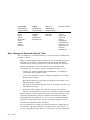
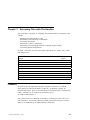
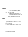
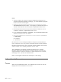
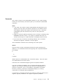
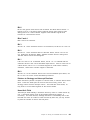
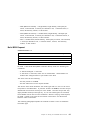
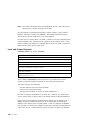
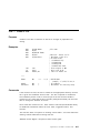
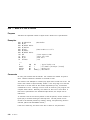
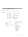
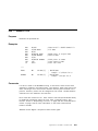
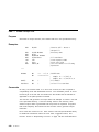
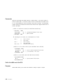
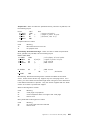
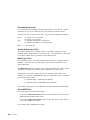
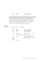
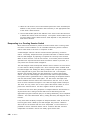
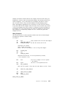
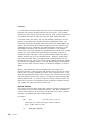
The following diagram shows the layout of the DOS boot record, it is placed
on all disks to provide an error message if the user trys to start the
workstation with a non-system disk in drive A:. If the disk is a system disk
the boot record points to the first address of the operating system.
00H
3 bytes
JUMP Instruction to Executable Code
03H
8 bytes
Optional OEM Name and Version
0BH
2 bytes
Bytes Per Sector
0DH
1 byte
Sectors Per Allocation Unit
0EH
2 bytes
Reserved Sectors (Starting at 0)
10H
1 byte
Number of File Allocation Tables
11H
1 byte
Number of Root Directory Entries
13H
2 bytes
Total Number of Sectors (if size is larger than
32MB, this value is 0 and the size is at offset
20H)
15H
1 byte
Media Descriptor
16H
2 byte
Number of Sectors Per FAT
18H
2 bytes
Sectors Per Track
1AH
2 bytes
Number of Heads
1CH
4 bytes
Number of Hidden Sectors
20H
4 bytes
Total Number of Sectors (See offset 13H)
24H
2 bytes
Physical Drive Number
26H
1 byte
Extended Boot Record Signature (29H)
27H
4 bytes
Volume Serial Number
2BH
11 bytes
Volume Label
36H
7 bytes
File System Identifier (FAT12 ),(FAT16 )....
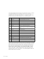
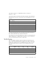
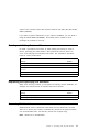
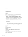
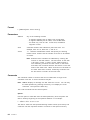
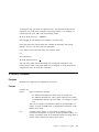
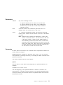
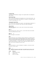
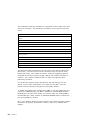
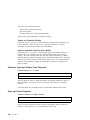
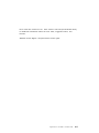
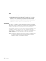
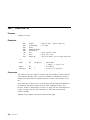
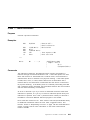
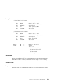
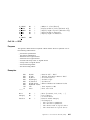
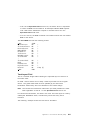
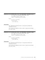
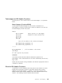
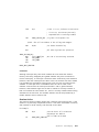
A boot record must be written on the first sector of all hard disks. A partition
table is found at the end of the boot record. The table is constructed of 16
byte entires and containing information about the partitions start and end
head, sector and cylinder positions. Also in the partition table is an boot
indicator which is used to determine if the partition is bootable, in which
case it is set to 80H. A system indicator byte is used to show the type of
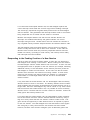
operating system that owns the partition. The following diagram shows the
partition table structure and offsets:
8
PC DOS 7
┌────────────────┬────────┬──────────┬─────────────────────────┐
│ Offset from │ Offset │ Size │
Description
│
│ start of Disk │
│
│
│
├────────────────┼────────┼──────────┼─────────────────────────┤
│ 1BEH
│ 00H
│ 1 byte │ Boot Indicator
│
│
│ 01H
│ 1 byte │ Beginning Head
│
│
│ 02H
│ 1 byte │ Beginning Sector
│
│
│ 03H
│ 1 byte │ Beginning Cylinder
│
│
│ 04H
│ 1 byte │ System Indicator
│
│
│ 05H
│ 1 byte │ Ending Head
│
│
│ 06H
│ 1 byte │ Ending Sector
│
│
│ 07H
│ 1 byte │ Ending Cylinder
│
│
│ 08H
│ 4 bytes │ Relative Starting Sector│
│
│ 0CH
│ 4 bytes │ Number of Sectors
│
├────────────────┼────────┼──────────┼─────────────────────────┤
│ 1CEH
│ 00H
│ 1 byte │ Boot Indicator
│
│
│ 01H
│ 1 byte │ Beginning Head
│
│
│ 02H
│ 1 byte │ Beginning Sector
│
│
│ 03H
│ 1 byte │ Beginning Cylinder
│
│
│ 04H
│ 1 byte │ System Indicator
│
│
│ 05H
│ 1 byte │ Ending Head
│
│
│ 06H
│ 1 byte │ Ending Sector
│
│
│ 07H
│ 1 byte │ Ending Cylinder
│
│
│ 08H
│ 4 bytes │ Relative Starting Sector│
│
│ 0CH
│ 4 bytes │ Number of Sectors
│
├────────────────┼────────┼──────────┼─────────────────────────┤
│ 1DEH
│ 00H
│ 1 byte │ Boot Indicator
│
│
│ 01H
│ 1 byte │ Beginning Head
│
│
│ 02H
│ 1 byte │ Beginning Sector
│
│
│ 03H
│ 1 byte │ Beginning Cylinder
│
│
│ 04H
│ 1 byte │ System Indicator
│
│
│ 05H
│ 1 byte │ Ending Head
│
│
│ 06H
│ 1 byte │ Ending Sector
│
│
│ 07H
│ 1 byte │ Ending Cylinder
│
│
│ 08H
│ 4 bytes │ Relative Starting Sector│
│
│ 0CH
│ 4 bytes │ Number of Sectors
│
├────────────────┼────────┼──────────┼─────────────────────────┤
│ 1EEH
│ 00H
│ 1 byte │ Boot Indicator
│
│
│ 01H
│ 1 byte │ Beginning Head
│
│
│ 02H
│ 1 byte │ Beginning Sector
│
│
│ 03H
│ 1 byte │ Beginning Cylinder
│
│
│ 04H
│ 1 byte │ System Indicator
│
│
│ 05H
│ 1 byte │ Ending Head
│
│
│ 06H
│ 1 byte │ Ending Sector
│
│
│ 07H
│ 1 byte │ Ending Cylinder
│
│
│ 08H
│ 4 bytes │ Relative Starting Sector│
│
│ 0CH
│ 4 bytes │ Number of Sectors
│
├────────────────┼────────┼──────────┼─────────────────────────┤
│ 1EFH
│
│ 2 bytes │ 55AAH Signature
│
└────────────────┴────────┴──────────┴─────────────────────────┘
Figure 1. Partition Table
The Boot Indicator has a value of 80H if the particular partition is bootable or
00H if the partition is not bootable.
The last entry in the partition table is the 55AAH signature and is used to
identify a valid boot record.
Chapter 2. Accessing Disks
9
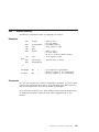
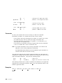
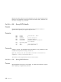
The following table show some of the system indicators that may be used:
00H
Unknown or no partition defined
01H
DOS 12 bit FAT (under 16MB)
04H
DOS 16 bit FAT (less than 65,536 sectors)
05H
Extended DOS partition
06H
DOS partition (over 32MB)
07H
OS/2 High Performance File System
Note
This table is by no means complete, as other manufactures use different
indicators.
The File Allocation Table (FAT)
The File Allocation Table (FAT) occupies the sectors immediately following
the boot record. If the FAT is larger than one sector, the sectors occupy
consecutive sector numbers.
The FAT keeps track of the physical location of all files on the disk. If the
FAT cannot be read because of a disk error, the contents of the files cannot
be located. For this reason, two copies of the FAT are written on the disk.
PC DOS 7 uses the FAT to allocate disk space to a file, one cluster at a time.
The FAT consists of a 12-bit entry (1.5 bytes) or a 16-bit entry (2 bytes) for
each cluster on the disk. On a hard disk, the number of sectors for each
cluster are determined by the size of the disk. PC DOS 7 determines
whether to create a 12-bit or 16-bit FAT by calculating the number of 8-sector
clusters that can occupy the space on the disk. If the number of clusters is
less than 4086, a 12-bit FAT is created. If it is greater, a 16-bit FAT is
created.
Using the following formula, you can determine the number of sectors on a
disk:
TS=SPT * H * C.
TS
SPT
H
C
10
PC DOS 7
= the total number of sectors on the disk.
= the number of sectors per track or per cylinder.
= the number of heads.
= the number of cylinders.
The number of sectors on a 10MB IBM hard disk, for example, is
20740 (17 * 4 * 305).
The first two entries in the FAT are not used to map data. They indicate the
size and format of the disk. The first byte of the FAT designates one of the
following:
Hex
Value
Meaning
FF
Double-sided, 8 sectors per track diskette
FE
Single-sided, 8 sectors per track diskette
FD
Double-sided, 9 sectors per track diskette
FC
Single-sided, 9 sectors per track diskette
F9
Double-sided, 15 sectors per track diskette (1.2 MB)
F9
Double-sided, 9 sectors per track diskette (720 KB)
F9
Double-sided, eXtended Data Format (1.88 MB)
F8
H a r d disk
F0
1.44MB or 2.88MB
The second and third bytes of the FAT contain the value FFH. The fourth
byte, used by 16-bit FATs only, contains the value FFH.
The maximum size 16-bit FAT supported by PC DOS 7 for media greater than
32KB is 64KB entries, or 128KB of space on the disk. This is an increase in
size from the IBM PC DOS 3.30 limit of 16KB entries.
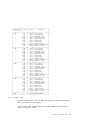
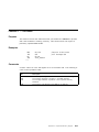
The Disk Directory
When the FORMAT command is issued, it builds the root directory for all
disks. If the disk is formatted with the /S option, the PC DOS 7 system files
(IBMBIO.COM, IBMDOS.COM, and COMMAND.COM) are added to the disk.
The following eight formats are used for 5.25-inch diskettes and 3.5-inch
diskettes:
Sides
Sectors/
Track
FAT
Size
Sectors
DIR
Sectors
DIR
Entries
Sectors/
Cluster
1 (5.25)
8
1
4
64
1
2 (5.25)
8
1
7
112
2
1 (5.25)
9
2
4
64
1
2 (5.25)
9
2
7
112
2
2 (5.25)
15
7
14
224
1
Chapter 2. Accessing Disks
11
Sides
Sectors/
Track
FAT
Size
Sectors
DIR
Sectors
DIR
Entries
Sectors/
Cluster
2 (3.5)
9
3
7
112
2
2 (3.5)
18
9
14
224
1
2 (3.5)
36
9
15
240
2
The Data Area
Data files and subdirectories are stored in the last and largest part of a disk.
Space is allocated as it is needed, a cluster at a time. This allocation
method permits the most efficient use of disk space. As clusters become
available, space can be allocated for new files.
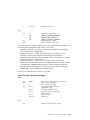
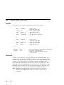
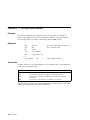
Accessing the Disk
Most interrupt 21H functions can be used to access a disk. Five other
functions can be used to perform disk-related activity.
Activity
Function
Number
Resetting the disk and flushing the file buffer
0DH
Selecting the default disk drive
0EH
Determine the current disk
19H
Determining the boot drive
3305H
Requesting the amount of free space on the disk
36H
Requesting Drive and Disk Information
Information on disks and drives can be requested by using the following INT
21H functions:
12
PC DOS 7
Activity
Function
Number
Requesting the current drive number
19H
Requesting disk allocation information about the default drive
1BH
Requesting disk allocation information about the specified drive
1CH
Reading and Writing Data Directly to the Disk
PC DOS 7 provides two interrupts, 25H and 26H, to read and write data to a
disk.
Activity
Interrupt
Number
Reading from specified disk sectors
25H
Writing to specified disk sectors
26H
Chapter 2. Accessing Disks
13
14
PC DOS 7
Chapter 3. Accessing Files with File Handles
The information necessary to complete the following tasks is provided in this
chapter:
•
•
•
•
•
•
Reading and writing data to a file
Requesting and specifying file attributes
Accessing directories
Searching for files in directories
Requesting and specifying National Language Support (NLS)
Controlling Network Operations.
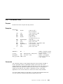
PC DOS 7 provides nine functions within interrupt 21H to create, open, close
and delete a file.
Activity
Function
Number
Creating a new file or replacing an old file
3CH
Opening a file
3DH
Closing a file handle
3EH
Deleting a file
41H
Renaming a file
56H
Creating a new file with a unique name
5AH
Creating a new file
5BH
Locking and unlocking read/write access to regions of a file
5CH
Creating and opening a file with extended parameters
6CH
Filenames
To name a file, the application program supplies a pointer to an ASCIIZ
string giving the name and location of the file. A filename contains an
optional drive letter, path, or file specification terminated with a hexadecimal
0 byte. Following is an example of a filename string:
′ B:\LEVEL1\LEVEL2\FILE1′ , 0
The maximum size of a filename is 64 bytes, including the path, name and
null terminator. All function calls that accept path names accept a forward
slash (/) or backslash (\) as path separator characters.
Copyright IBM Corp. 1995
15
File Handles
The open or create function calls return a 16-bit value called a file handle .
To perform file I/O, a program uses the file handle to reference the file.
Once a file is opened, the program no longer needs to maintain the ASCIIZ
string pointing to the file. PC DOS 7 keeps track of the location of the file,
regardless of which directory is current.
Activity
Function
Number
Specifying an additional file handle for a file
45H
Pointing the existing file handle to another file
46H
Specifying the number of open file handles
67H
The number of file handles that can be open at one time by all processes can
be specified with the FILES command in CONFIG.SYS. There are 20 default
handles available to a single process. All handles inherited by a process
can be redirected.
Each open handle is associated with a single file or device, but several
handles can reference the same file or device. Thus, the maximum handle
limit can exceed the number specified with the FILES command.
Special File Handles
PC DOS 7 provides five special file handles for use by application programs.
The handles are:
0000H Standard input device (STDIN)
0001H Standard output device (STDOUT)
0002H Standard error device (STDERR)
0003H Standard auxiliary device (STDAUX)
0004H Standard printer device (STDPRN)
File handles associated with standard devices do not need to be opened by a
program, but a program can close them. STDIN should be treated as a
read-only file. STDOUT and STDERR should be treated as write-only files.
STDIN and STDOUT can be redirected. Function calls 01H through 0CH
access the standard devices.
The standard device handles are useful for performing I/O to and from the
console device. For example, you can read input from the keyboard using
the read function call (3FH) and file handle 0000H (STDIN); you can also write
16
PC DOS 7
output to the console screen with the write function call (40H) and file handle
0001H (STDOUT).
If you want to prevent redirection of your output to STDOUT, you can send it
using file handle 0002H (STDERR). This facility also is useful for error
messages or prompts to the user.
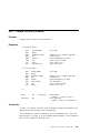
Reading and Writing Data to a File
PC DOS 7 provides five functions to allow reading and writing to a file or
device, specifying the offset within a file at which the read or write is to
occur, and verifying the read-after-write state. The verification operation,
however, slows performance.
Activity
Function
Number
Reading from a file or device
3FH
Writing to a file or device
40H
Specifying the address (through the pointer) at which a read or write is
to occur
42H
Requesting the read-after-write state
54H
Specifying the read-after-write state
2EH
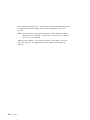
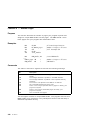
Requesting and Specifying File Attributes
While a file is being created, your program can specify certain attributes; for
example, the date and time of creation and level of access.
Activity
Function
Number
Requesting and specifying a file′s attributes
43H
Requesting and specifying a file′s date and time
57H
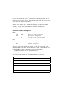
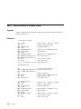
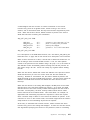
Accessing Subdirectories
Subdirectories, that is, directories other than the root directories, are files.
There is no limit to the number of subdirectory entries if the physical media
can accommodate them. All directory entries are 32 bytes long.
Note: Values are in hexadecimal.
Chapter 3. Accessing Files with File Handles
17
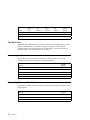
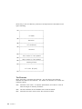
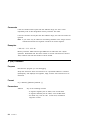
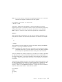
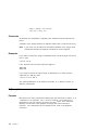
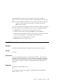
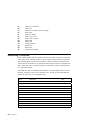
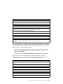
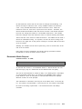
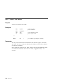
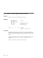
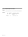
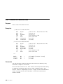
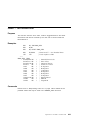
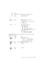
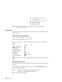
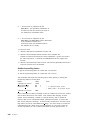
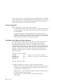
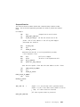
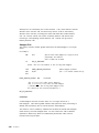
Each entry in the root directory consists of 32 bytes that are described in the
figure following:
00H ┌────────────────────────────────────┐
│
│
│
│
│
Filename
│
│
│
08H ├────────────────────────────────────┤
│
Extension
│
│
│
0BH ├────────────────────────────────────┤
│
File Attribute
│
0CH ├────────────────────────────────────┤
│
│
│
Reserved
│
│
│
│
│
16H ├────────────────────────────────────┤
│
Time created or last updated
│
18H ├────────────────────────────────────┤
│
Date created or last updated
│
1AH ├────────────────────────────────────┤
│
Starting Cluster
│
1CH ├────────────────────────────────────┤
│
│
│
│
│
File Size (4 bytes)
│
│
│
20H └────────────────────────────────────┘
The Filename
Bytes 0 through 7 represent the filename. The first byte of the filename
indicates the status of the filename. The status of a filename can contain the
following values:
18
PC DOS 7
00H
Filename never used. To improve performance, this value is used to
limit the length of directory searches.
05H
The first character of the filename has an E5H character.
E5H
Filename has been used, but the file has been erased.
2EH
The entry is for a directory. If the second byte is also 2EH, the cluster
field contains the cluster number of this directory′s parent directory.
(Cluster number 0000H is specified if the parent directory is the root
directory.)
Any other character is the first character of a filename.
Note: Byte offsets are in decimal.
.
The Filename Extension
Bytes 8 through 10 indicate the filename extension.
The File Attribute
Byte 11 indicates the file′s attribute. The attribute byte is mapped as follows:
01H
Indicates a read-only file. An attempt to open the file for output using
function call 3DH or 6CH results in an error code being returned.
02H
Indicates a hidden file. The file is excluded from normal directory
searches.
04H
Indicates a system file. The file is excluded from normal directory
searches.
08H
Indicates the entry contains the volume label in the first 11 bytes. The
entry contains no other usable information and may exist only in the
root directory.
10H
Indicates the entry defines a subdirectory and is excluded from normal
directory searches.
20H
Indicates an archive bit. The bit is set ON when the file has been
written to and closed. It is used by the BACKUP and RESTORE
commands for determining whether the file has been changed since it
was created or last updated. This bit can be used along with other
attribute bits.
All other bits are reserved and must be 0.
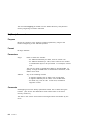
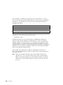
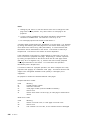
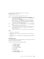
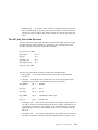
The File Creation/Last Changed Time
Bytes 22 and 23 contain the time when the file was created or last updated.
The time is mapped in the bits as follows:
<
23
> <
22
>
15 14 13 12 11 10 9 8 7 6 5 4 3 2 1 0
h h h h h m m m m m m x x x x x
Where:
Chapter 3. Accessing Files with File Handles
19
hh = the binary number of hours (0-23)
mm = the binary number of minutes (0-59)
xx = the binary number of two-second increments
The time is stored with the least significant byte first.
The File Creation Date
Bytes 24 and 25 contain the date when the file was created or last updated.
The date ( mm/dd/yy ) is mapped in the bits as follows:
<
25
> <
24
>
15 14 13 12 11 10 9 8 7 6 5 4 3 2 1 0
y y y y y y y m m m m d d d d d
Where:
yy = 0 − 1 1 9 ( 1 9 8 0 − 2 0 9 9 )
mm = 1 − 1 2
dd = 1 − 3 1
The date is stored with the least significant byte first.
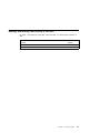
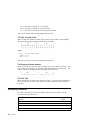
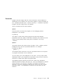
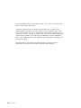
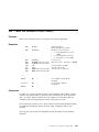
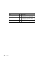
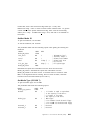
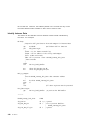
The Starting Cluster Number
Bytes 26 and 27 contain the cluster number of the first cluster in the file. The
first cluster for data space on all hard disks and diskettes is cluster 002. The
cluster number is stored with the least significant byte first.
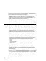
<
27
> <
26
>
0 0 0 0 0 0 0 0 0 0 1 0 0 0 0 1
The File Size
Bytes 28 through 31 contain the file size in bytes. The first word contains the
low-order part of the size. Both words are stored with the least significant
byte first.
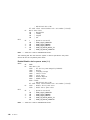
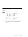
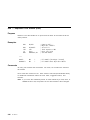
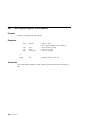
Accessing Directories
PC DOS 7 provides four functions within interrupt 21H to create, identify,
change or delete directories.
20
PC DOS 7
Activity
Function
Number
Removing a subdirectory
3AH
Creating a subdirectory
39H
Changing to another directory
3BH
Identifying the current directory
47H
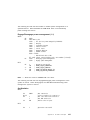
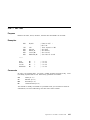
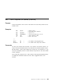
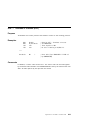
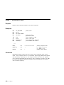
Finding Files in Directories
PC DOS 7 provides two functions within interrupt 21H to search for the first
matching entry and the next matching entry.
Activity
Function
Number
Searching for the first matching entry
4EH
Searching for the next matching entry
4FH
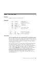
Requesting and Specifying National Language Support (NLS)
PC DOS 7 provides the following functions for NLS:
Activity
Function
Number
Specifying the current country
38H
Requesting the country dependent information
38H
Providing double-byte character set (DBCS) support
65H
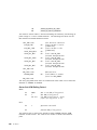
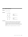
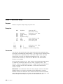
Controlling Network Operations
Several PC DOS 7 function calls accept a network path as input if the IBM PC
Local Area Network support is loaded. If network access is available, further
information is noted in the ″Comments″ section under each relevant function
call in Appendix B, “PC DOS 7 Function Calls” on page 133.
A network path consists of an ASCII string containing a computer name,a
directory path, and an optional filename. The network path cannot contain a
drive specifier. The path is terminated by a byte of binary 0′s. Following is
an example:
SERVER1LEVEL1LEVEL2FILE1
Many function calls that accept an ASCIIZ string as input accept a network
path. If you want to execute function 5BH (Create a New File), for example,
you must have Read/Write/Create or Write/Create access to the directory to
be able to create a file. If you have Read Only or Write Only access and no
Create access, you cannot create a file in the directory. Two function calls
that do not accept a network path as input are Change Current Directory
(3BH) and Find First Matching File (4EH).
Chapter 3. Accessing Files with File Handles
21
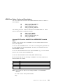
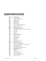
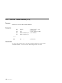
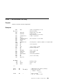
The following function calls are available to control network operations:
22
PC DOS 7
Activity
Function
Number
Locking and unlocking read/write access to a region of a file
5CH
Writing all data from a file to a device
68H
Requesting the local computer ID
5E00H
Specifying the printer setup string
5E02H
Requesting the printer setup string
5E03H
Requesting redirection
5F02H
Attaching to a redirect device
5F03H
Canceling redirection
5F04H
Chapter 4. Accessing Files Using File Control Blocks
This chapter provides guide and system architecture information to assist in
performing the following tasks:
•
•
•
•
Accessing files
Accessing sequential records
Accessing random records
Finding files in directories
The File Control Block (FCB)
With few exceptions, a program should maintain files using File Control
Blocks (FCBs) only to run under DOS 1.10. File handles are the
recommended method for accessing files.
One FCB maintained by your program and PC DOS 7 is required for each
open file. Your program must supply a pointer to the FCB and fill in the
appropriate fields required by specific function calls.
A program should not attempt to use the reserved fields in the FCB. Bytes 0
through 15 and 32 through 36 must be set by the user program. Bytes 16
through 31 are set by PC DOS 7 and must not be changed by user programs.
An unopened FCB consists of the FCB prefix (if used), the drive number, the
filename, and the extensions appropriately specified. An open FCB is one in
which the remaining fields have been specified by the create or open
function calls.
All word fields are stored with the least significant byte first. For example, a
record length of 128 is stored as 80H at offset 14, and 00H at offset 15.
Figure 2 on page 24 gives further explanation.
Copyright IBM Corp. 1995
23
-7 ┌───────┬────────────────────────────────────┬──────────┐
│
│
│
│
│ hex FF│
Zeros
│ Attribute│
0┌───────┼───────┴────────────────────────────────────┴──────────┤
│
│
│
│ Drive │
Filename (8bytes) or reserved device name
│
8├───────┼───────────────────────┬───────────────┬───────────────┤
│
│
│
│
│
│
│ Filename extension │ Current block │ Record size │
16├───────┴───────┬───────────────┼───────────────┼───────────────┤
│ File size │ File size │
│
│
│ (low part) │ (high part) │
Date
│
│
24├───────────────┴───────────────┴───────────────┘
│
│
│
│
Reserved for system use
│
32├───────┬───────────────┬───────────────┬───────────────────────┘
│Current│ Random record │Random record │
│record │number (low pt)│number(high pt)│
└───────┴───────────────┴───────────────┘
FCB
extension
Standard
FCB
Figure 2. The File Control Block
Areas 16 through to 31 are filled in by DOS and must not be modified.
Other areas are filled in by the using program.
Note: Offsets are in decimal.
The FCB is formatted as follows:
Drive Number
Byte 0 represents the drive number. For example, before the file is opened,
0 equals the default drive, 1 equals drive A, and 2 equals drive B. After the
file is opened, 0 equals drive A, 1 equals drive A, and 2 equals drive B.
The actual drive number replaces the 0 when a file is opened.
Filename
Bytes 1 through 8 represent the filename, left-justified with trailing blanks. If
a reserved device name such as LPT1 is specified here, do not include the
colon.
24
PC DOS 7
Filename Extension
Bytes 9 through 11 represent the filename extension, left-justified with trailing
blanks or all blanks.
Current Block Number
Bytes 12 through 13 represent the current block number relative to the
beginning of the file, starting with 0. The 0 is set by the open function call. A
block consists of 128 records, each size specified in the logical record size
field. The current block number is used with the current record field for
sequential reads and writes.
Logical Record Size
Bytes 14
the open
80H, you
locations
through 15 represent the logical record size in bytes. 80H is set by
function call. If you want to change the logical record size from
can reset the value. PC DOS 7 uses the value to determine
in the file for all disk reads and writes.
File Size
Bytes 16 through 19 represent file size in bytes. In this two-word field, the
first word is the low-order part of the size.
File Date
Bytes 20 through 21 represent the date the file was created or last updated.
The date ( mm/dd/yy ) is mapped in the bits as follows:
<
21
> <
20
>
15 14 13 12 11 10 9 8 7 6 5 4 3 2 1 0
y y y y y y y m m m m d d d d d
where:
yy is 0-119 (1980-2099)
mm is 1-12
dd is 1-31
Reserved
Bytes 22 through 31 are reserved.
Record Number in Block
Byte 32 represents the current relative record number (0-127) within the
current block. You must set this field before doing sequential read and write
operations to the diskette. This field is not initialized by the open function
call.
Chapter 4. Accessing Files Using File Control Blocks
25
Record Number within File
Bytes 33 through 36 represent the record number relative to the beginning of
the file, starting with 0. You must set this field before doing random read
and write operations to the diskette. This field is not initialized by the open
function call.
If the record
size is more
use the FCB
overlaps the
size is less than 64 bytes, both words are used. If the record
than 64 bytes, only the first 3 bytes are used. Note that if you
at 5CH in the program segment, the last byte of the FCB
first byte of the unformatted parameter area.
The Extended FCB
The extended FCB is used to create or search in the disk directory for files
with special attributes. The extension adds a 7-byte prefix to the FCB,
formatted as follows:
Extended FCB
FCB byte -7 contains FFH to indicate an extended FCB.
Reserved
FCB bytes -6 to -2 are reserved.
File Attribute
FCB byte -1 represents an attribute byte. Function calls 00H through 2EH are
valid for both the standard FCB and the extended FCB. If you are using an
extended FCB, the appropriate register should be set to the first byte of the
prefix, rather than the drive number field.
The Disk Transfer Area (DTA)
PC DOS 7 uses a buffer in memory, the Disk Transfer Area (DTA), to hold the
data for FCB file reads and writes. The DTA can be at any location within
the data area of your program and should be specified by your program.
Only one DTA can be in effect at a time, so your program must tell PC DOS 7
which memory location to use before issuing disk read or write functions.
When a program is given control by COMMAND.COM, a default DTA large
enough to hold 128 bytes is established at 80H in the program segment
prefix.
PC DOS 7 provides the following functions within interrupt 21H to handle DTA
activities:
26
PC DOS 7
Activity
Function
Number
Specifying the buffer address for reading and writing data in the DTA
1AH
Requesting the buffer address for reading and writing data in the DTA
2FH
Accessing Files
An FCB can identify a file on any valid drive, but only in the current directory
of the specified drive.
If SHARE has not been loaded, the number of files that can be open at a time
(using FCB function calls) is not restricted. When file sharing is loaded,
however, the maximum number of FCB opened files is limited by the value
specified in the FCBS command in CONFIG.SYS. The m value specifies the
total number of files that can be opened by FCBS.
When the maximum number of FCB opens is exceeded, PC DOS 7
automatically closes the least recently used file. Any attempt to access such
a file results in the interrupt 24H critical error message, “FCB not available.”
If this situation occurs while a program is running, the value specified for m
in the FCBS command should be increased.
Do not use the same FCB to open a second file without closing the first open
file. If more than one file is to be opened concurrently, use separate FCBs.
To avoid potential file sharing problems, close files after I/O is performed.
Close the file before trying to delete or rename an open file.
Managing files using the FCBS command can be performed using the
following function calls:
Activity
Function
Number
Opening a file
0FH
Closing a file
10H
Deleting a file
13H
Creating a file
16H
Renaming a file
17H
Requesting the file size
23H
Separating the filename information into its components (parsing)
29H
Chapter 4. Accessing Files Using File Control Blocks
27
Accessing Sequential Records
By using the current block, current record, and record length fields of the
FCB, you can perform sequential I/O by using the following sequential read
or write function calls within interrupt 21H:
Activity
Function
Number
Reading from a record
14H
Writing to a record
15H
Accessing Random Records
Random I/O can be performed by filling in the random record and record
length fields in the FCB and issuing the following function calls within
interrupt 21H:
Activity
Function
Number
Reading from a single record
21H
Writing to a single record
22H
Specifying the random record field in the FCB
24H
Reading from multiple records
27H
Writing to multiple records
28H
Finding Files in Directories
Using the FCB as a source, finding and changing files in directories is
performed by the following functions within interrupt 21H:
28
PC DOS 7
Activity
Function
Number
Searching for the first matching file entry
11H
Searching for the next matching file entry
12H
Deleting a file
13H
Creating a file
16H
Renaming a file
17H
Separating the filename information into its components (parsing)
29H
Chapter 5. Managing Device I/O
This chapter provides guide and system architecture information about the
following tasks:
•
•
•
•
•
Managing display I/O
Managing keyboard I/O
Managing miscellaneous I/O
Managing file system activities
Accessing the system device drivers′ control channel.
Managing Display I/O
PC DOS 7 provides four functions within interrupt 21H that send characters or
strings of characters to the screen.
Activity
Function
Number
Outputting a character to the screen, with the ability to trigger the
control-break interrupt handler
02H
Waiting until a character is input and outputting it to the screen without
the ability to trigger the control-break interrupt handler
06H
Outputting a string of characters in memory to the screen
09H
Outputting a string of characters in a buffer to the screen or writing the
string to a file device
40H
For further information on specifying character attributes, foreground and
background screen colors, and screen size using ANSI.SYS, see the PC DOS
7 User ′ s Guide and Reference .
Managing Keyboard I/O
PC DOS 7 provides a full complement of functions within interrupt 21H that
your application program can use to manage keyboard I/O.
Activity
Function
Number
Sending input from the keyboard (with echo) to the display
01H
Receiving input directly from the keyboard, or sending output directly to
the display
06H
Receiving input directly from the keyboard without echo
07H
Copyright IBM Corp. 1995
29
Activity
Function
Number
Receiving input from the keyboard without echo to the display with the
ability to trigger the control-break interrupt handler
08H
Reading characters from the keyboard to the buffer
0AH
Checking the keyboard buffer status
0BH
Clearing the keyboard buffer; specifying which function to call after
clearing the buffer
0CH
For further information on reassigning the keys using ANSI.SYS, see the PC
DOS 7 User ′ s Guide and Reference .
Managing Miscellaneous I/O
Three functions are available to manage miscellaneous I/O.
Activity
Function
Number
Receiving auxiliary input
03H
Sending auxiliary output
04H
Printing output
05H
Managing File System Activities
The following system activities are supported by PC DOS 7:
30
PC DOS 7
Activity
Function
Number
Requesting the local computer ID
5E00H
Specifying the printer setup string
5E02H
Requesting the printer setup string
5E03H
Requesting redirection list
5F02H
Attaching to a redirect device
5F03H
Canceling redirection
5F04H
Writing all data from a file to a device
68H
Accessing the System Device Drivers′ Control Channel
Function 44H within interrupt 21H is a multi-purpose function for accessing
the device drivers′ control channel. Using function 44H, your application
program can request the status of a device and read and write to the I/O
control channel. The following subfunction values should be passed in AL:
Category
Activity
Subfunction
Number
Requesting and specifying device
information
Requesting device information
00H
Specifying device information
01H
Reading and writing data to a
character device
Reading from a character device
02H
Writing to a character device
03H
Reading and writing data to a
block device
Reading from a block device
04H
Writing to a block device
05H
Requesting and specifying device
information
Determining whether a device
contains removable media
08H
Providing network support for
devices
Determining whether a logical
device is local or remote
09H
Determining whether a file handle
is local or remote
0AH
Specifying how many times (and
intervals) PC DOS 7 should try to
resolve shared file conflicts
0BH
Controlling I/O for file handles
0CH
Requesting and specifying the
logical drive
Controlling I/O for block devices
0DH
Requesting the logical drive
0EH
Specifying the logical drive
0FH
Chapter 5. Managing Device I/O
31
Reading and Writing Data in Binary and ASCII Modes
A program can use function 44H to change the mode in which data is read or
written to a device. If I/O is performed in binary mode, control values have
no meaning. If I/O is performed in ASCII mode, certain control values have
meaning. They are shown in the following table:
Control
Value
Keyboard
Input
Meaning
03H
∧C
Control B r e a k
04H
∧D
End of Task
10H
∧P
Print Screen
11H
∧Q
Scroll restart
13H
∧S
Scroll Lock
0AH
∧J
Line Feed
0DH
∧M
Carriage Return
1AH
∧Z
End-Of-File
When a file is read in ASCII mode, it is echoed to the display and tabs are
expanded into spaces. They are left as a tab byte (09H) in the input buffer.
When a file is written in ASCII mode, tabs are expanded to 8-character
boundaries and filled with spaces (20H).
32
PC DOS 7
Chapter 6. Controlling Processes
This chapter provides guide and system architecture information about the
following activities:
•
•
•
•
•
•
•
•
•
•
Allocating memory
Identifying a program at load time
Loading and executing overlays
Terminating a program/subprogram
Loading an overlay without executing it
Calling a command processor
Responding to errors
Responding to a control-break action
Requesting and specifying the system date and time
Requesting and specifying the interrupt vectors.
Allocating Memory
PC DOS 7 keeps track of allocated and available memory blocks and
provides three function calls for application programs to communicate their
memory requests.
Activity
Function
Number
Allocating m e m o r y
48H
Freeing allocated memory
49H
Changing the size of blocks of allocated memory
4AH
PC DOS 7 Memory Management
PC DOS 7 manages memory by allocating 16-byte units called paragraphs
and building a control block for each allocated block. Any allocation is 16
bytes larger than the actual request because PC DOS 7 automatically
allocates a control block to keep track of each allocated block.
When the user starts the program at the command line, COMMAND.COM
loads the executable program module into the largest unused block of
available memory and reads the file header. If there is not enough memory
available, the system returns an error code and passes control to the
program. Your program should use the SETBLOCK function call (4AH) to
reduce allocated memory to the size it needs.
Copyright IBM Corp. 1995
33
Note: Because it is likely that the default stack supplied by PC DOS 7 lies in
the area of memory being freed, a .COM program should remember to
set up its own stack before issuing a SETBLOCK. The SETBLOCK call
frees unneeded memory which then can be used for loading
subsequent programs.
If your program requires additional memory during processing, issue function
call 48H within interrupt 21. To free memory, issue function call 49H within
interrupt 21.
The PC DOS 7 Memory Map
The following table illustrates the order in which PC DOS 7 components and
application programs are located in memory when PC DOS 7 is loaded low
and no HMA exists.
Location
Use
0000:0000
Interrupt vector table
0040:0000
ROM communication area
0050:0000
PC DOS 7 communication area
0070:0000
IBMBIO.COM −
XXXX:0000
IBMDOS.COM −
functions)
XXXX:0000
PC DOS 7 buffers, control areas, and installed device drivers
XXXX:0000
Resident portion of COMMAND.COM − Interrupt handlers for interrupts
22H (terminate), 23H (Ctrl-Break), 24H (critical error), and code to reload
the transient portion
XXXX:0000
External command or utility − . COM or .EXE file
XXXX:0000
User stack for .COM files
XXXX:0000
Transient portion of COMMAND.COM
PC DOS 7 interface to ROM I/O routines
PC DOS 7 interrupt handlers, service routines (INT 21
The following table illustrates the order in which the PC DOS 7 components
and application programs are located in memory when PC DOS 7 is loaded
high.
34
PC DOS 7
Location
Use
0000:0000
Interrupt vector table
0040:0000
ROM communication area
0050:0000
PC DOS 7 communication area
0070:0000
Resident BIOS data −
points
XXXX:0000
PC DOS 7 data
also including device driver headers and entry
Location
Use
XXXX:0000
PC DOS 7 installable device drivers and data structures that are
allocated by SYSINIT
FFFF:0010
VDISK header (see note below)
FFFF:0030
IBMBIO
XXXX:XXXX
IBM DOS
Memory map addresses are in segment:offset format. For example,
0070:0000 is absolute address 00700H.
Note: The VDISK header is placed at the start of the HMA as a precaution
because most INT 15 allocations respect VDISK headers.
The PC DOS 7 Communication Area is used as follows:
0050:0000 Print screen status flag store
0
Print screen not active or successful print screen operation
1
Print screen in progress
255
Error encountered during print screen operation
0050:0001 Used by BASICA
0050:0004 Single-drive mode status byte
0
Diskette for drive A was last used
1
Diskette for drive B was last used
0050:0010—0021
Used by BASICA
0050:0022—002F
Used by PC DOS 7 for diskette initialization
0050:0030—0033
Used by MODE command.
All other locations within the 256 bytes beginning at 0050:0000 are reserved
for PC DOS 7 use.
Chapter 6. Controlling Processes
35
Identifying a Program at Load Time
PC DOS 7 provides two function calls for application programs to specify and
identify themselves at load time:
Activity
Function
Number
Creating the means for PC DOS 7 to identify a program at load time
through the program segment prefix (PSP)
26H
Requesting how PC DOS 7 identified a program at load time
62H
The Program Segment
When you enter an external command or call a program with the EXEC
function call (4BH), PC DOS 7 determines the lowest available address in
memory and assigns it to the program. That area of memory is called the
program segment . At offset 0 within the program segment, PC DOS 7 builds
a program segment prefix control block. When an EXEC is issued, PC DOS 7
loads the program at offset 100H and gives it control. See Figure 3 on
page 37 for an illustration of the program segment prefix.
36
PC DOS 7
┌───────┬───────┬───────┬───────┬───────┬───────┬───────┬───────┐
│
0
│
1
│
2
│
3
│
4
│
5
│
6
│
7
│
├───────┴───────┼───────┴───────┼───────┴───────┴───────┴───────┤
│
INT
│
Top of
│
│
│
20H
│
memory
│
Reserved
│
├───────┬───────┼───────┬───────┼───────┬───────┬───────┬───────┤
│
8
│
9
│
A
│
B
│
C
│
D
│
E
│
F
│
├───────┴───────┼───────┴───────┼───────┴───────┼───────┴───────┤
│
│
Terminate
│
Terminate
│ Ctrl-break
│
│
Reserved
│
address
│
address
│ exit address │
│
│
IP
│
CS
│
IP
│
├───────┬───────┼───────┬───────┼───────┬───────┼───────┬───────┤
│ 10
│ 11
│ 12
│ 13
│ 14
│ 15
│ 16
│ 17
│
├───────┴───────┼───────┴───────┴───────┴───────┼───────┴───────┤
│ Ctrl-break
│
Critical error
│
│
│ exit address │
exit address
│
Reserved
│
│
CS
│
IP
CS
│
│
├───────────────┴───────────────┬───────┬───────┼───────┬───────┤
│ 18
to
2B
│ 2C
│ 2D
│ 2E
│ 2F
│
├───────────────────────────────┼───────┴───────┼───────┴───────┤
│
│ Environment │
│
│
Reserved
│
pointer
│
Reserved
│
├───────────────────────────────┴───────────────┴───────────────┤
│ 30
to
4F
│
├───────────────────────────────────────────────────────────────┤
│
Reserved
│
├───────┬───────┬───────┬───────┬───────┬───────┬───────┬───────┤
│ 50
│ 51
│ 52
│ 53
│ 54
│ 55
│ 56
│ 57
│
├───────┴───────┼───────┴───────┴───────┴───────┴───────┴───────┤
│
DOS call
│
Reserved
│
├───────┬───────┼───────┬───────┬───────┬───────┬───────┬───────┤
│ 58
│ 59
│ 5A
│ 5B
│ 5C
│ 5D
│ 5E
│ 5F
│
├───────┴───────┴───────┴───────┼───────┴───────┴───────┴───────┤
│
Reserved
│
Unopened Standard FCB1
│
├───────┬───────┬───────┬───────┼───────┬───────┬───────┬───────┤
│ 60
│ 61
│ 62
│ 63
│ 64
│ 65
│ 66
│ 67
│
├───────┴───────┴───────┴───────┴───────┴───────┴───────┴───────┤
│
Unopened Standard FCB1 (continued)
│
├───────┬───────┬───────┬───────┬───────┬───────┬───────┬───────┤
│ 68
│ 69
│ 6A
│ 6B
│ 6C
│ 6D
│ 6E
│ 6F
│
├───────┴───────┴───────┴───────┼───────┴───────┴───────┴───────┤
│
Unopened Standard FCB1
│
Unopened Standard FCB2
│
│
(continued)
│
│
├───────┬───────┬───────┬───────┼───────┬───────┬───────┬───────┤
│ 70
│ 71
│ 72
│ 73
│ 74
│ 75
│ 76
│ 77
│
├───────┴───────┴───────┴───────┴───────┴───────┴───────┴───────┤
│
Unopened Standard FCB2 (continued)
│
├───────┬───────┬───────┬───────┬───────┬───────┬───────┬───────┤
│ 78
│ 79
│ 7A
│ 7B
│ 7C
│ 7D
│ 7E
│ 7F
│
├───────┴───────┴───────┴───────┴───────┴───────┴───────┴───────┤
│
Unopened Standard FCB2 (continued)
│
├───────┬───────┬───────┬───────┬───────┬───────┬───────┬───────┤
│ 80
│ 81
│ 82
│ 83
│ 84
│ 85
│ 86
│ 87
│
├───────┼───────┴───────┴───────┴───────┴───────┴───────┴───────┤
│ Param │
Command parameters
┴
│ Length│
starting with leading blanks
┬
├───────┼───────┬───────┬───────┬───────┬───────┬───────┬───────┤
│ F8
│ F9
│ FA
│ FB
│ FC
│ FD
│ FE
│ FF
│
├───────┴───────┴───────┴───────┴───────┴───────┴───────┴───────┤
┴
│
┬
Command parameters
│
└───────────────────────────────────────────────────────────────┘
Figure 3. The Program Segment Prefix
Chapter 6. Controlling Processes
37
The program segment prefix′s first segment of available memory is in
paragraph form; that is, 1000H represents 64KB. The word at offset 6
contains the number of bytes available in the segment.
Offset 2CH contains the environment′s paragraph address.
Offset 50H contains code to invoke the PC DOS 7 function dispatcher. By
placing the desired function number in AH, a program can issue a long call
to PSP+50H to invoke a PC DOS 7 function rather than issuing an interrupt
21H.
The default disk transfer address is set to 80H.
An unformatted parameter area at 81H contains all the characters entered
after the command name, including leading and imbedded delimiters, with
80H set to the number of characters. If the <, >, or | parameters were
entered on the command line, they and the filenames associated with them
will not appear in this area because redirection of standard input and output
is transparent to applications.
For .COM files, offset 6 (one word) contains the number of bytes available in
the segment.
Register AX contains the drive specifiers entered with the first two
parameters as follows:
AL=FFH if the first parameter contained an invalid drive specifier
(otherwise AL=00H).
AH=FFH if the second parameter contained an invalid drive specifier
(otherwise AH=00H).
In .EXE programs DS and ES registers are set to point to the program
segment and CS, IP, SS, and SP registers are set to the values passed by the
Linker.
In .COM programs all four segment registers contain the segment address of
the initial allocation block, starting with the program segment prefix control
block. The instruction pointer (IP) is set to 100H. The SP register is set to
the end of the program′s segment. The segment size at offset 6 is rounded
down to the paragraph size.
38
PC DOS 7
Loading and Executing Overlays
Your program can use the 4BH function call to load optional overlays.
Function 4BH, value 0, loads and executes a program with overlays.
Function 4BH, value 3, loads an overlay without executing it.
If your program calls an overlay, the EXEC call assumes the calling program
has already allocated memory for the overlay. The request to load an
overlay does not verify that the calling program owns the memory into which
the overlay is to be loaded. An overlay loaded into memory not allocated to
it can damage the PC DOS 7 memory management control blocks. This will
not be evident until PC DOS 7 needs to use its series of control blocks.
If a memory allocation error is returned, the problem must be corrected and
the system restarted. Overlays should not issue SETBLOCK calls because
they do not own the memory in which they operate. The memory is
controlled by the calling program.
The Parameter Block
When your program calls a subprogram using the EXEC call (4BH), it can
pass a parameter block which provides the subprogram with the following:
•
•
•
The environment string
A command line which permits it to act like another command processor
File control blocks at 5C and 6C in the program segment prefix
(optional).
The Environment String
The environment passed from the calling program is a copy of its
environment. The segment address of the passed environment is contained
at offset 2CH in the program segment prefix.
The environment is a series of ASCII strings totaling less than 32KB in the
form:
NAME=parameter
Note: NAME= is always in uppercase.
Each string is terminated by a byte of 0′s. The complete series of strings is
terminated by another byte of 0′s. Another ASCII string containing the word
count and an ASCIIZ string containing the executable program′s drive, path,
filename, and extension follow the series of environment strings.
The environment built by the command processor and passed to all called
programs contains a COMSPEC= string , the last PATH, APPEND and
Chapter 6. Controlling Processes
39
PROMPT commands issued, and any environment strings specified with the
SET command.
The Command Line
Your program must create a command line which will be transferred to the
subprogram.
The File Control Blocks
If your program is using files based on file handles, the file control blocks are
of no concern. If your program is using file control blocks, and either 5CH or
6CH contain a pathname, the corresponding FCB will contain only a valid
drive number. The filename field will not be valid.
Terminating a Program/Subprogram
PC DOS 7 provides four functions and two interrupts to terminate programs.
It also provides an interrupt to permit your program to specify where control
is to be passed upon termination.
Activity
Function
Number
Terminating a program
00H
Terminating a program with a specified portion remaining in memory
31H
Terminating a program and passing control to the calling process
4CH
Determining how a process ended
4DH
Interrupt 20H terminates a program. Interrupt 27H terminates a program with
a specified portion remaining in memory. Interrupt 22H specifies where
control is to be passed upon program termination.
When a subprogram terminates, control is returned to the calling program.
Before terminating, the calling program must return to the system the
memory it allocated to the subprogram. When the calling program
terminates, control is returned to PC DOS 7. PC DOS 7 does a CHECKSUM
to determine if the transient portion of COMMAND.COM has been modified.
If it has, PC DOS 7 reloads COMMAND.COM based on the path specified in
the environment.
The program returns from executing in one of the following methods:
•
•
•
40
PC DOS 7
By a jump to offset 0 in the program segment prefix
By issuing an INT 20H
By issuing an INT 21H with register AH=00H or 4CH
•
By calling location 50H in the program segment prefix with AH=00H or
4CH.
Using INT 21H is the preferred method. All programs must ensure that the
CS register contains the segment address of the program segment prefix
when terminating using any of the preceding methods except call 4CH.
All of the preceding methods return control to the program that issued the
EXEC. During the process, interrupt vectors 22H, 23H, and 24H (terminate,
Ctrl-Break, and critical error exit addresses) are restored from the values
saved in the program segment prefix of the terminating program. Control is
then given to the terminating address.
Loading an Overlay without Executing It
If AL=3 is specified within function call 4BH, no program segment prefix is
built, and DOS assumes the calling program has allocated memory for the
overlay. The calling program should provide memory in one of two ways:
•
•
Provide enough memory for the overlay when it issues the SETBLOCK
call (4AH)
Free adequate memory with the 49H call.
When DOS receives an AL=3 request, the system assumes that the
requested memory is owned by the calling program. As in subprograms, an
overlay can be loaded into memory not allocated to it and damage the series
of DOS memory management control blocks.
Programs loaded with AL=3 should not issue the SETBLOCK call (4AH)
because the memory in which they operate is owned by the calling process,
not the overlay. Before terminating, the calling program must return to the
system the memory it allocated to the overlay. When the calling program
terminates, control is returned to DOS.
Calling a Command Processor
To call a command processor, you must do the following:
•
•
Assure that adequate free memory is available to contain the second
copy of the command processor and the command it is to execute. Issue
function call 4AH to shrink allocated memory to your current
requirement. Issue function call 48H with BX=FFFFH. The return is
available memory.
Build a parameter string for the secondary command processor in the
form:
Chapter 6. Controlling Processes
41
1 byte = length of parameter string
xx b y t e = parameter string
1 byte = 0DH (carriage return)
For example, the following assembly statement builds the string to
execute a DISKCOPY command:
DB 19, ″ / C C:DISKCOPY A: B:″ , 13
•
Use the EXEC function call (4BH, function value 0) to execute the
secondary copy of the command processor. The COMSPEC =
parameter in the environment passed at PSP+2CH identifies the drive,
directory, and command processor name. Remember to set offset 2 in
the EXEC control block to point to the parameter string.
Responding to Errors
When a PC DOS 7 function cannot be performed (indicating a critical error
situation) control is transferred to interrupt 24H. Function 59H provides
additional information on the error condition.
Activity
Number
Responding to a critical error situation
Interrupt 24H
Requesting additional error information and suggested action
Function 59H
Handle function calls report an error by setting the carry flag and returning
the error code in AX. FCB function calls report an error by returning FFH in
AL.
The Extended Error function call (59H) provides a common set of error codes
and specific error information such as error classification, location, and
recommended action. In most critical cases, applications can analyze the
error code and take specific action. Recommended actions are intended for
programs that do not understand the error codes. Programs can take
advantage of extended error support both from interrupt 24H critical error
handlers and after issuing interrupt 21H function calls. Do not code to
specific error codes.
Responding to a Control-Break Action
Interrupt 23H is issued if a Ctrl-Break occurs during standard I/O. Function
calls 09H and 0AH can be used if there is a ∧ C, carriage return and line feed
produced as output.
42
PC DOS 7
Activity
Function
Number
Displaying string
09H
Buffering keyboard input
0AH
Responding to a control-break action
23H
If a Ctrl-Break is entered during standard input, standard output, standard
printer, or asynchronous communications adapter operations, an INT 23H is
executed. If BREAK is on, INT 23H is checked on most function calls, except
06H and 07H.
The user-written Ctrl-Break routine can use function calls 09H, 0AH, and 0DH
to respond to the Ctrl-Break action by having ^C, carriage return, and line
feed produced as output. ASCII codes 0DH and 0AH represent carriage
return and line feed, respectively. If the Ctrl-Break routine saves all
registers, it may end with an IRET (return from interrupt) instruction to
continue program execution. If the routine returns with a long return, the
carry flag is used to determine whether or not to stop execution. If the carry
flag is not set, execution continues, as with an IRET.
There are no restrictions on what the Ctrl-Break handler is allowed to do,
providing the registers are unchanged if IRET is used.
Chapter 6. Controlling Processes
43
Requesting and Specifying the System Date and Time
The following functions get or set the system date and time:
Activity
Function
Number
Requesting the system date
2AH
Specifying the system date
2BH
Requesting the system time
2CH
Specifying the system time
2DH
Requesting and Specifying the Interrupt Vectors
A program can create and change the contents of the interrupt vectors , the
4-byte addresses of the routines in memory that service hardware and
software interrupts. On exit, the program must reset the interrupt vectors to
where they were pointing originally.
If you want a program to examine or specify the contents of an interrupt
vector, use PC DOS 7 function calls 35H and 25H and avoid referencing the
interrupt vector locations directly.
44
PC DOS 7
Activity
Function
Number
Specifying the interrupt vector value
25H
Requesting the interrupt vector value
35H
Chapter 7. Debugging a Program
This chapter describes how to use the DEBUG.COM program that is shipped
as part of PC DOS 7 to identify and fix problems in your programs.
Warning
Use of the DEBUG program should not be undertaken lightly, the utility
has the power to alter code, always ensure that you take a backup copy
of the code that you will be using debug on.
The DEBUG Utility
DEBUG provides a controlled testing environment that enables you to
monitor the execution of a program. You can make changes directly to a
.COM or an .EXE file and execute the file immediately to determine whether
your changes fixed a problem. You do not need to reassemble source code
files first. DEBUG allows you to load, alter, or display any file and to execute
object files as well.
Starting the DEBUG.COM Program
To start DEBUG, enter information in the following format:
DEBUG [ [ drive:] [ path]filename [testfile-parameters]]
You can enter just the DEBUG command, or you can include a file
specification. The parameters parm1 and parm2 represent input and output
specifications of the program you are debugging. For example, suppose you
wanted to monitor the execution of the PC DOS 7 DISKCOMP utility. You
enter:
DEBUG DISKCOMP.COM A: B:
The DEBUG program loads DISKCOMP into memory and displays the DEBUG
prompt:
The hyphen (-) tells you DEBUG is ready to accept commands to alter,
display, or execute the contents of the program in memory.
Copyright IBM Corp. 1995
45
If you enter just DEBUG without a file specification, you can either work with
the present memory contents or you can load a required file into memory
using the DEBUG Name and Load commands.
Entering Commands at the DEBUG Prompt
A DEBUG command consists of a single letter, usually followed by one or
more parameters. For example, the Name command is entered at the
DEBUG prompt as a single letter followed by a file specification:
-N MYPROG
A command and its parameters can be entered in uppercase, lowercase, or
a combination of both. The command and its parameters can be separated
by delimiters; however, delimiters are only required between two
consecutive hexadecimal values. Thus, the following Dump commands are
equivalent:
dcs:100 110
d cs:100 110
d,cs:100,110
A command is activated only after you press the Enter key. If you want to
terminate a command and return to the DEBUG prompt, simultaneously
press the Ctrl and Break keys.
For commands producing a large amount of output, you can simultaneously
press the Ctrl and Num Lock keys (or Pause key if available) to suspend the
display and then press any key to restart the display, or you can redirect the
command′s output to a file.
When DEBUG encounters a syntax error in a line, it displays the line with the
error identified as follows:
d cs:100 CS:100
^error 110
In this example, the Dump command expects the second address to contain
only a hexadecimal offset value. It finds the S, which is not a hexadecimal
character.
46
PC DOS 7
DEBUG Command Summary
The table below lists the DEBUG commands and describes the debugging
operations you can perform with them. Complete format descriptions and
examples for each command can be found starting on page 49.
Command
Task Description
A (Assemble)
Assemble IBM Macro Assembler statements directly into
m e m ory.
C (Compare)
Compare the contents of two blocks of memory.
D (Dump)
Dump the contents of a portion of memory to the display or
redirect it to a file.
E (Enter)
Make changes to bytes in memory.
F (Fill)
Fill a range of memory with byte values.
G (Go)
Execute the program in memory from one address to the
breakpoint address and then display the next instruction.
H (Hex)
Add and subtract two hexadecimal values and display the
results.
I (Input)
Display the input in the first byte next to the port.
L (Load)
Load the contents of absolute disk sectors or a file specified
by the Name command into memory.
M (Move)
Copy the contents of a block of memory to another location.
N (Name)
Set up file control blocks and file specification information for
Load and Write commands.
O (Output)
Send a byte to an output port.
P (Proceed)
Execute a subroutine call, loop instruction, interrupt, or repeat
string instruction and return control to DEBUG at the next
instruction.
Q (Quit)
End the DEBUG session without saving the debugged program.
R (Register)
Display the contents of registers and the settings of flags.
S (Search)
Search a range of memory for characters.
T (Trace)
Execute one or more instructions in your program and display
the contents of registers and flags after each instruction.
U (Unassemble)
Translate the contents of memory into Assembler-like
statements, displaying their addresses and hexadecimal
values.
W (Write)
Write the debugged program to absolute disk sectors or to the
original file loaded with DEBUG.
XA (Allocate)
Allocate a specified number of expanded memory pages to an
EMS handle.
XD (Deallocate)
Deallocate an EMS handle.
X M (Map)
Map an EMS logical page to an EMS physical page from an
EMS handle.
XS (Status)
Display the status of expanded memory.
Chapter 7. Debugging a Program
47
The DEBUG Work Space
When the DEBUG program starts, the registers and flags are set to the
following values for the program being debugged:
•
•
•
•
•
The segment registers (CS, DS, ES, and SS) are set to the bottom of free
memory; that is, the first segment after the end of the DEBUG program.
The Instruction Pointer (IP) is set to hex 0100.
The Stack Pointer (SP) is set to the end of the segment, or the bottom of
the transient portion of the program loader, whichever is lower. The
segment size at offset 6 is reduced by hex 100 to allow for a stack that
size.
The remaining registers (AX, BX, CX, DX, BP, SI, and DI) are set to 0.
However, if you start the DEBUG program with a file specification, the CX
register contains the length of the file in bytes. If the file is greater than
64KB, the length is contained in registers BX and CX (the high portion in
BX).
The initial state of the flags is:
NV UP EI PL NZ NA PO NC
•
The default disk transfer address is set to hex 80 in the code segment.
All of available memory is allocated. At this point, the loaded program is
unable to allocate memory.
.EXE Files
If a file loaded by DEBUG has an extension of .EXE, DEBUG does the
necessary relocation and sets the segment registers, stack pointer, and
instruction pointer to the values defined in the file. The DS and ES registers,
however, point to the program segment prefix at the lowest available
segment. The BX and CX registers contain the size of the program that is
smaller than the file size.
The program is loaded at the high end of memory if the appropriate
parameter was specified when the linker created the file.
.HEX Files
If a file loaded by DEBUG has an extension of .HEX, the file is assumed to be
in INTEL hex format, and is converted to executable form while being loaded.
48
PC DOS 7
A (Assemble) Command
Purpose
Assembles macro assembler language statements directly into memory.
Format
A [ address ]
Parameters
address
Use any of the following formats:
•
•
•
A segment register plus an offset, such as CS:0100
A segment address plus an offset, such as 4BA:0100
An offset only, such as 100. In this case, the default
segment is used.
Comments
All numeric input to the Assemble command is in hexadecimal. The
assembly statements you enter are assembled into memory at successive
locations, starting with the address specified in address . If no address is
specified, the statements are assembled into the area at CS:0100, if no
previous Assemble command was used, or into the location following the last
instruction assembled by a previous Assemble command. After all desired
statements have been entered, press the Enter key when you are prompted
for the next statement to return to the DEBUG prompt.
DEBUG responds to invalid statements by displaying:
∧error
and re-displaying the current assemble address.
DEBUG supports standard 8086/8088 assembly language syntax (and the 8087
instruction set), with the following rules:
•
All numeric values entered are hexadecimal and can be entered as 1
through 4 characters.
•
Prefix mnemonics are entered in front of the opcode to which they refer.
They can also be entered on a separate line.
•
The segment override mnemonics are CS:, DS:, ES:, and SS:.
Chapter 7. Debugging a Program
49
•
String manipulation mnemonics must specify the string size. For
example, MOVSW must be used to move word strings and MOVSB must
be used to move byte strings.
•
The mnemonic for the far return is RETF.
•
The assembler will automatically assemble short, near, or far jumps and
calls depending on byte displacement to the destination address. These
can be overridden with the NEAR or FAR prefix. For example:
0100:0500 JMP 502
; a 2 byte short jump
0100:0502 JMP NEAR 505 ; a 3 byte near jump
0100:0505 JMP FAR 50A ; a 5 byte far jump
The NEAR prefix can be abbreviated to NE, but the FAR prefix cannot be
abbreviated.
•
DEBUG cannot tell whether some operands refer to a word memory
location or a byte memory location. In this case, the data type must be
explicitly stated with the prefix WORD PTR or BYTE PTR. DEBUG will also
accept the abbreviations WO and BY. For example:
NEG
DEC
•
DEBUG also cannot tell whether an operand refers to a memory location
or to an immediate operand. DEBUG uses the common convention that
operands enclosed in square brackets refer to memory. For example:
MOV
MOV
•
•
BYTE PTR [128]
WO [SI]
AX,21
AX,[21]
; Load AX with 21H
; Load AX with the contents of memory location 21H
Two popular pseudo-instructions have also been included. The DB
opcode assembles byte values directly into memory. The DW opcode
assembles word values directly into memory. For example:
DB
DB
DB
1,2,3,4,″THIS IS AN EXAMPLE″
′ THIS IS A QUOTE: ″ ′
″THIS IS AN APOSTROPHE:′ ″
DW
1000,2000,3000,″BACH:″
All forms of the register indirect commands are supported. For example:
ADD BX,34[BP+2] [ SI-1]
POP [BP+DI]
PUSH [SI]
•
50
PC DOS 7
All opcode synonyms are supported. For example:
•
LOOPZ
LOOPE
100
100
JA
JNBE
200
200
For numeric co-processor opcodes the WAIT or FWAIT prefix must be
explicitly specified. For example:
FWAIT FADD ST,ST(3)
FLD TBYTE PTR [BX]
;This line will assemble a FWAIT prefix
;This line will not
Examples
C>debug
-a200
08B4:0200 xor ax,ax
08B4:0202 mov [bx],ax
08B4:0204 ret
08B4:0205
C (Compare) Command
Purpose
Compares the contents of two blocks of memory.
Format
C range address
Parameters
range
Either of these two formats:
•
•
An address followed by an offset, such as CS:100 110.
An address followed by L value , where value is the number
of hexadecimal bytes to be processed. For example, CS:100
L 10.
The limit for range is hexadecimal 10000 or decimal 64KB. To
specify a range of 64KB within 4 hexadecimal characters, enter
0000 or 0 for value .
Chapter 7. Debugging a Program
51
address
Any of these three formats:
•
•
•
A segment register plus an offset, such as CS:0100.
A segment address plus an offset, such as 4BA:0100.
An offset only, such as 100. In this case, the default
segment is used.
Comments
The contents of the two blocks of memory are compared; the length of the
comparison is determined from the range . If unequal bytes are found, their
addresses and contents are displayed, in the form:
addr1 byte1 byte2 addr2
where, the first half (addr1 byte1) refers to the location and contents of the
mismatching locations in range , and the second half (byte2 addr2) refers to
the byte found in address .
If you enter only an offset for the beginning address of range , the C
command assumes the segment contained in the DS register. To specify an
ending address for range , enter it with only an offset value.
Examples
C 100 L20 200
The 32 bytes (hex 20) of memory beginning at DS:100 are compared with the
32 bytes beginning at DS:200. L20 is the range.
D (Dump) Command
Purpose
Displays the contents of a portion of memory.
Format
D [ address ]
or
D [ range ]
52
PC DOS 7
Parameters
address
Any of the following formats:
•
•
•
range
A segment register plus an offset, such as CS:0100.
A segment address plus an offset, such as 4BA:0100.
An offset only, such as 100. In this case, the default
segment is used.
Either of these two formats:
•
•
An address followed by an offset, such as CS:100 110.
An address followed by L value , where value is the number
of hexadecimal bytes to be processed. For example, CS:100
L 10.
The limit for range is hexadecimal 10000 or decimal 64K bytes.
To specify a range of 64K bytes within 4 hexadecimal
characters, enter 0000 or 0 for value .
Comments
The dump is displayed in two parts:
1. A hexadecimal portion. Each byte is displayed in hexadecimal.
2. An ASCII portion. The bytes are displayed as ASCII characters.
Unprintable characters (ASCII 0 to 31 and 127 to 255) are indicated by a
period.
With a 40-column system display format, each line begins on an 8-byte
boundary and shows 8 bytes.
With an 80-column system display format, each line begins on a 16-byte
boundary and shows 16 bytes. There is a hyphen between the 8th and 9th
bytes.
Note: The first line may have fewer than 8 or 16 bytes if the starting address
of the dump is not on a boundary. In this case, the second line of the
dump begins on a boundary.
The Dump command has two format options.
Option 1
Use this option to display the contents of hex 40 bytes (40-column mode) or
hex 80 bytes (80-column mode). For example:
Chapter 7. Debugging a Program
53
D address
or
D
The contents are dumped starting with the specified address.
If you do not specify an address, the D command assumes the starting
address is the location following the last location displayed by a previous D
command. Thus, it is possible to dump consecutive 40-byte or 80-byte areas
by entering consecutive D commands without parameters.
If no previous D command was entered, the location is offset hex 100 into the
segment originally initialized in the segment registers by DEBUG.
Note: If you enter only an offset for the starting address, the D command
assumes the segment contained in the DS register.
Option 2
Use this option to display the contents of the specified address range. For
example:
D range
Note: If you enter only an offset for the starting address, the D command
assumes the segment contained in the DS register. If you specify an
ending address, enter it with only an offset value.
For example:
D cs:100 10C
A 40-column display format might look like this:
04BA:0100 42 45 52 54 41 20 54 00
BERTA T.
04BA:0108 20 42 4F 52 47
BORG
54
PC DOS 7
E (Enter) Command
Purpose
•
Replaces the contents of one or more bytes, starting at the specified
address, with the values contained in the list (see Option 1).
•
Displays and allows modification of bytes in a sequential manner (see
Option 2).
Format
E address [ list ]
Parameters
address
Any of the following formats:
•
•
•
list
A segment register plus an offset, such as CS:0100.
A segment address plus an offset, such as 4BA:0100.
An offset only, such as 100. In this case, the default
segment is used.
A string of byte values. If you include a character string,
enclose the characters in single or double quotation marks. To
specify a quotation mark as a character within the string when it
is also used to delimit the string, type it twice.
″These ″″quotes″″ are correct.″
′ This one′ ′ s okay, too.′
Comments
If you enter only an offset for the address, the E command assumes the
segment contained in the DS register.
The Enter command has two format options.
Option 1
Use this option to place the list in memory beginning at the specified
address.
E address list
For example:
E ds:100 F3 ″xyz″ 8D
Chapter 7. Debugging a Program
55
Memory locations ds:100 through ds:104 are filled with the 5 bytes specified
in the list.
Option 2
Use this option to display the address and the byte of a location, then the
system waits for your input.
For example:
E address
Enter a 1- or 2-character hexadecimal value to replace the contents of the
byte; then take any one of the following actions:
1. Press the space bar to advance to the next address. Its contents are
displayed. If you want to change the contents take option 1, above.
To advance to the next byte without changing the current byte, press the
space bar again.
2. Enter a hyphen to back up to the preceding address. A new line is
displayed with the preceding address and its contents. If you want to
change the contents, take option 1, above.
To back up one more byte without changing the current byte, enter
another hyphen.
3. Press the Enter key to end the Enter command.
Note: Display lines can have 4 or 8 bytes of data, depending on whether the
system display format is 40- or 80-column. Spacing beyond an 8-byte
boundary causes a new display line, with the beginning address, to be
started.
For example:
E cs:100
might cause this display:
04BA:0100 EB.
To change the contents of 04BA:0100 from hex EB to hex 41, enter 41.
04BA:0100 EB.41
To see the contents of the next three locations, press the space bar three
times. The screen might look like this:
04BA:0100 EB.41 10. 00. BC.
56
PC DOS 7
To change the contents of the current location (04BA:0103) from hex BC to
hex 42, enter 42.
04BA:0100 EB.41 10. 00. BC.42
Now, suppose you want to back up and change the hex 10 to hex 6F. This is
what the screen looks like after entering two hyphens and the replacement
byte:
04BA:0100 EB.41 10.00. BC.4204BA:0102 00.04BA:0101 10.6F
Press the Enter key to end the Enter command. The hyphen prompt will
appear.
F (Fill) Command
Purpose
Fills the memory locations in the range with the values in the list.
Format
F range list
Parameters
range
Either of these two formats:
•
•
An address followed by an offset, such as CS:100 110
An address followed by L value , where value is the number
of hexadecimal bytes to be processed. For example, CS:100
L 10.
The limit for range is hexadecimal 10000 or decimal 64K bytes.
To specify a range of 64K bytes within 4 hexadecimal
characters, enter 0000 or 0 for value .
list
A string of byte values. If you include a character string,
enclose the characters in single or double quotation marks. To
specify a quotation mark as a character within the string when it
is also used to delimit the string, type it twice.
″These ″″quotes″″ are correct.″
′ This one′ ′ s okay, too.′
Chapter 7. Debugging a Program
57
Comments
If the list contains fewer bytes than the address range, the list is used
repeatedly until all the designated memory locations are filled.
If the list contains more bytes than the address range, the extra list items are
ignored.
Note: If you enter only an offset for the starting address of the range, the Fill
command assumes the segment contained in the DS register.
Examples
F 4BA:100 L 5 F3 ″XYZ″ 8D
Memory locations 04BA:100 through 04BA:104 are filled with the 5 bytes
specified. Remember that the ASCII values of the list characters are stored.
Thus, locations 100-104 will contain F3 58 59 5A 8D.
G (Go) Command
Purpose
Executes the program you are debugging.
Stops the execution when the instruction at a specified address is reached
(breakpoint), and displays the registers, flags, and the next instruction to be
executed.
Format
G [ = address ] [ address [ address ...]]
Parameters
address
Any of the following formats:
•
•
•
58
PC DOS 7
A segment register plus an offset, such as CS:0100.
A segment address plus an offset, such as 4BA:0100.
An offset only, such as 100. In this case, the default
segment is used.
Comments
Program execution begins with the current instruction, whose address is
determined by the contents of the CS and IP registers, unless overridden by
t h e = address parameter (the = must be entered). I f = address is specified,
program execution begins with CS:= address .
The Go command has two format options.
Option 1
Use this option to execute the program you are debugging without
breakpoints. For example:
G [=address]
This option is useful when testing program execution with different
parameters each time. (Refer to the Name command.) Be certain the CS:IP
values are set properly before issuing the G command, if not using
= address .
Option 2
This option performs the same function as Option 1 but, in addition, allows
breakpoints to be set at the specified addresses. For example:
G [=address] address
[address...]
This method causes execution to stop at a specified location so the system
or program environment can be examined.
You can specify up to ten breakpoints in any order. You may wish to take
advantage of this if your program has many paths, and you want to stop the
execution no matter which path the program takes.
The DEBUG program replaces the instruction codes at the breakpoint
addresses with an interrupt code (hex CC). If any one breakpoint is reached
during execution, the execution is stopped, the registers and flags are
displayed, and all the breakpoint addresses are restored to their original
instruction codes. If no breakpoint is reached, the instructions are not
restored.
Chapter 7. Debugging a Program
59
Notes:
1. Once a program has reached completion (DEBUG has displayed the
“Program terminated normally” message), you must reload the program
before it can be executed again.
2. Make sure that the address parameters refer to locations that contain
valid 8086/8088 instruction codes. If you specify an address that does not
contain valid instruction in the first byte, unpredictable results occur.
3. The stack pointer must be valid and have 6 bytes available for the Go
command, otherwise, unpredictable results occur.
4. If only an offset is entered for a breakpoint, the G command assumes the
segment contained in the CS register.
5. Do not set breakpoints at instructions in read-only memory (ROM BIOS
or ROM BASIC).
For example:
G 102 1EF 208
Be careful not to set a breakpoint between a segment override indication
(such as ES; alone on a line), and the instruction that the override qualifies.
Execution begins with the current instruction, whose address is the current
values of CS:IP. T h e = address parameter was not used.
Three breakpoints are specified; assume that the second is reached.
Execution stops before the instruction at location CS:1EF is executed, the
original instruction codes are restored, all three breakpoints are removed,
the display occurs, and the Go command ends.
Refer to the Register command for a description of the display.
H (Hexarithmetic) Command
Purpose
Adds the two hexadecimal values, then subtracts the second from the first.
Displays the sum and difference on one line.
60
PC DOS 7
Format
H value value
Examples
H 0F 8
0017 0007
The hexadecimal sum of 000F and 0008 is 0017, and their difference is 0007.
I (Input) Command
Purpose
Inputs and displays (in hexadecimal) 1 byte from the specified port.
Format
I portaddress
Parameters
portaddress A 1− 4 character hexadecimal value specifying an 8- or 16-bit
port address.
Examples
I 2F8
6B
The single hexadecimal byte read from port 02F8 is displayed (6B).
L (Load) Command
Purpose
Loads a file or absolute disk sectors into memory.
Chapter 7. Debugging a Program
61
Format
L [ address [ drive sector sector ]]
Parameters
address
Any of the following formats:
•
•
•
A segment register plus an offset, such as CS:0100.
A segment address plus an offset, such as 4BA:0100.
An offset only, such as 100. In this case, the default
segment is used.
drive
A decimal number that indicates a particular drive. For
example, drive A is 0, drive B is 1, and so on.
sector
1− 3 character hexadecimal values that specify the starting
relative sector number and the number of sectors to be loaded
or written.
Note: Relative sector numbers are obtained by counting the
sectors on the disk surface. The first sector on the disk
is at track 0, sector 1, head 0, and is relative sector 0.
The numbering continues for each sector on that track
and head, then continues with the first sector on the next
head of the same track. When all sectors on all heads of
the track have been counted, numbering continues with
the first sector on head 0 of the next track.
Comments
The maximum number of sectors that can be loaded with a single Load
command is hex 80. A sector contains 512 bytes.
Note: DEBUG displays a message if a disk read error occurs. You can retry
the read operation by pressing the F3 key to re-display the Load
command. Then press the Enter key.
The Load command has two format options.
Option 1
Use this option to load data from the disk specified by drive and place the
data in memory beginning at the specified address . For example:
L address drive sector sector
The data is read from the specified starting relative sector (first sector) and
continues until the requested number of sectors is read (second sector).
62
PC DOS 7
Note: If you only enter an offset for the beginning address, the L command
assumes the segment contained in the CS register.
For example, to load data, you might enter:
L DS:100 1 0F 6D
The data is loaded from the diskette in drive B and placed in memory
beginning at DS:100. Consecutive sectors of data are transferred, 6DH (109),
starting with relative sector hex 0F (15) (the 16th sector on the diskette).
Note: Option 1 cannot be used if the drive specified is a network drive.
Option 2
When issued without parameters, or with only the address parameter, use
this option to load the file whose file specification is at CS:80. For example:
L
or
L address
This condition is met by specifying the file name when starting the DEBUG
program, or by using the Name command.
Note: If DEBUG was started with a file specification and subsequent Name
commands were used, you may need to enter a new Name command
for the proper file specification before issuing the Load command.
The file is loaded into memory beginning at CS:100 (or the location specified
by address ), and is read from the drive specified in the file specification, or
from the default drive, if none was specified. Note that files with extensions
of .COM or .EXE are always loaded at CS:100. If you specified an address, it
is ignored.
The BX and CX registers are set to the number of bytes read; however, if the
file being loaded has an extension of .EXE, the BX and CX registers are set
to the actual program size. The file may be loaded at the high end of
memory. Refer to “The DEBUG Work Space” on page 48 for the conditions
that are in effect when .EXE or .HEX files are loaded.
For example:
DEBUG
-N myprog
-L
-
Chapter 7. Debugging a Program
63
The file named myprog is loaded from the default directory and placed in
memory beginning at location CS:0100.
M (Move) Command
Purpose
Moves the contents of the memory locations specified by range to the
locations beginning at the address specified.
Format
M range address
Parameters
range
Either of these two formats:
•
•
An address followed by an offset, such as CS:100 110.
An address followed by L value , where value is the number
of hexadecimal bytes to be processed. For example, CS:100
L 10.
The limit for range is hexadecimal 10000 or decimal 64KB. To
specify a range of 64KB within 4 hexadecimal characters, enter
0000 or 0 for value .
address
Any of the following formats:
•
•
•
A segment register plus an offset, such as CS:0100.
A segment address plus an offset, such as 4BA:0100.
An offset only, such as 100. In this case, the default
segment is used.
Comments
Overlapping moves are always performed without loss of data during the
transfer. (The source and destination areas share some of the same
memory locations.)
The data in the source area remains unchanged unless overwritten by the
move.
64
PC DOS 7
Notes:
1. If you enter only an offset for the beginning address of the range, the M
command assumes the segment contained in the DS register. If you
specify an ending address for the range, enter it with only an offset
value.
2. If you enter only an offset for the address of the destination area, the M
command assumes the segment contained in the DS register.
Examples
M CS:100 L10 500
The 17 bytes of data from CS:100 through CS:110 are moved to the area of
memory beginning at DS:500.
N (Name) Command
Purpose
•
Formats file control blocks for the first two file specifications, at CS:5C
and CS:6C. (Starting DEBUG with a file specification also formats a file
control block at CS:5C.)
The file control blocks are set up for the Load and Write commands and
to supply required file names for the program being debugged.
•
All file specifications and other parameters, including delimiters, are
placed exactly as entered in a parameter save area at CS:81, with CS:80
containing the number of characters entered. Register AX is set to
indicate the validity of the drive specifiers entered with the first two file
specifications.
Format
N [ d: ] [ path ] filename [ .ext ]
Comments
If you start the DEBUG program without a file specification, you must use the
Name command before a file can be loaded with the L command.
Chapter 7. Debugging a Program
65
Examples
DEBUG
-N myprog
-L
To define file specifications or other parameters required by the program
being debugged, enter:
DEBUG myprog
-N file1 file2
In this example, DEBUG loads the file myprog at CS:100, and leaves the file
control block at CS:5C formatted with the same file specification. Then, the
Name command formats file control blocks for file1 and file2 at CS:5C and
CS:6C, respectively. The file control block for myprog is overwritten. The
parameter area at CS:81 contains all characters entered after the N,
including all delimiters, and CS:80 contains the count of those characters
(hex 0C).
O (Output) Command
Purpose
Sends the byte to the specified output port.
Format
O portaddress byte
Parameters
portaddress A 1− 4 character hexadecimal value specifying an 8- or 16-bit
port address.
Examples
To send the byte value 4F to output port 2F8, enter:
O 2F8 4F
66
PC DOS 7
P (Proceed) Command
Purpose
Causes the execution of a subroutine call, a loop instruction, an interrupt, or
a repeat string instruction to stop at the next instruction.
Format
P [ = a d d r e s s ] [ value ]
Parameters
address
Any of the following formats:
•
•
•
A segment register plus an offset, such as CS:0100.
A segment address plus an offset, such as 4BA:0100.
An offset only, such as 100. In this case, the default
segment is used.
A 1− 4 character hexadecimal value, specifying the number of
instructions to execute.
value
Comments
When at a subroutine call, a loop instruction, an interrupt, or a repeat string
instruction, issue the Proceed command to execute the instruction (perform
the entire function), and return control at the next instruction. The Proceed
command has the same syntax as the Trace command. Specifying P0 is the
same as specifying T0.
Examples
If the following instructions are executed:
0100
0103
..
.
1000
..
.
1XXX
CALL
JC
1000
2000
XOR
AX,AX
RET
And if CS:IP was pointing to the CALL 1000 instruction, typing P causes the
execution of the subroutine and returns control to DEBUG at the JC
instruction.
Chapter 7. Debugging a Program
67
Q (Quit) Command
Purpose
Ends the DEBUG program.
Format
Q
Comments
The file that you are working on in memory is not saved by the Quit
command. You must use the Write command to save the file.
DEBUG returns to the command processor which then issues the normal
command prompt.
Examples
-Q
A>
R (Register) Command
Purpose
The Register command has the following three functions:
•
Displays the hexadecimal contents of a single register with the option of
changing those contents
•
Displays the hexadecimal contents of all the registers, plus the
alphabetic flag settings, and the next instruction to be executed
•
Displays the eight 2-letter alphabetic flag settings with the option of
changing any or all of them.
Format
R [ registername ]
68
PC DOS 7
Parameters
registername
The valid names are:
AX
BX
CX
DX
SP
BP
SI
DI
CS
DS
ES
SS
IP
F
IP refers to the instruction pointer, and F refers to the flags
register.
Comments
When the DEBUG program starts, the registers and flags are set to certain
values for the program being debugged. (Refer to “The DEBUG Work Space”
on page 48.)
Display a Single Register
To display the contents of a single register, enter the register name:
R AX
The system might respond with:
AX F1E4
:
Now you can take one of two actions: press the Enter key to leave the
contents unchanged, or change the contents of the AX register by entering a
1-4 character hexadecimal value, such as hex FFF.
AX F1E4
:FFF
Now, pressing the Enter key changes the contents of the AX register to hex
0FFF.
Display All Registers and Flags
To display the contents of all registers and flags and the next instruction to
be executed, type:
R
The system responds:
AX=0E00 BX=00FF CX=0007 DX=01FF SP=039D BP=0000 SI=005C DI=0000
DS=3D5B ES=3D5B SS=3D5B CS=3D5B IP=011A NV UP EI PL NZ NA PO NC
3D5B:011A CD21
INT
21
Chapter 7. Debugging a Program
69
The first four lines display the hexadecimal contents of the registers and the
eight alphabetic flag settings. The last line indicates the location of the next
instruction to be executed and its hexadecimal and unassembled formats.
This is the instruction pointed to by CS:IP.
A system with an 80-column display shows:
1st line - 8 registers
2nd line - 5 registers and 8 flag settings
3rd line - next instruction information
A system with a 40-column display shows:
1st line - 4 registers
2nd line - 4 registers
3rd line - 4 registers
4th line - 1 register and 8 flag settings
5th line - next instruction information
Display All Flags
There are eight flags, each with two-letter codes to indicate either a set
condition or a clear condition. The flags appear in displays in the order
shown in the following table:
Flag Name
Set
Clear
Overflow (yes/no)
OV
NV
Direction (decrease/increase)
DN
UP
Interrupt (enable/disable)
EI
DI
Sign (negative/positive)
NG
PL
Z e r o (yes/no)
ZR
NZ
Auxiliary carry (yes/no)
AC
NA
Parity (even/odd)
PE
PO
C a r r y (yes/no)
CY
NC
To display all flags, enter:
R F
If all the flags are in a set condition, the response is:
OV DN EI NG ZR AC PE CY Now you can either press the Enter key to leave the settings unchanged or
change any or all of the settings.
70
PC DOS 7
To change a flag, just enter its opposite code. The opposite codes can be
entered in any order with or without intervening spaces. For example, to
change the first, third, fifth, and seventh flags, enter:
OV DN EI NG ZR AC PE CY - PONZDINV
The changes in this example are entered in reverse order.
Press the Enter key and the flags are modified as specified, the prompt
appears, and you can enter the next command.
If you want to see if the new codes are in effect, enter:
R F
The response is:
NV DN DI NG NZ AC PO CY The first, third, fifth, and seventh flags are changed as requested. The
second, fourth, sixth, and eighth flags are unchanged. A single flag can be
changed only once for each R F command.
S (Search) Command
Purpose
Searches the range for the character(s) in the list .
Format
S range list
range
Either of these two formats:
•
•
An address followed by an offset, such as CS:100 110.
An address followed by L value , where value is the number
of hexadecimal bytes to be processed. For example, CS:100
L 10.
The limit for range is hexadecimal 10000 or decimal 64KB. To
specify a range of 64KB within 4 hexadecimal characters, enter
0000 or 0 for value .
list
A string of byte values. If you include a character string,
enclose the characters in single or double quotation marks. To
specify a quotation mark as a character within the string when it
is also used to delimit the string, type it twice.
Chapter 7. Debugging a Program
71
″These ″″quotes″″ are correct.″
′ This one′ ′ s okay, too.′
Comments
All matches are indicated by displaying the addresses where matches are
found.
A display of the prompt without an address means that no match was found.
Note: If you enter only an offset for the starting address of the range, the S
command assumes the segment contained in the DS register.
Examples
If you want to search the range of addresses from CS:100 through CS:110 for
hex 41, type:
S CS:100 110 41
If two matches are found the response might be:
04BA:0104
04BA:010D
If you want to search the same range of addresses for a match with the
4-byte list (41 ″ A B ″ E), enter:
S CS:100 L 11 41 ″AB″ E
The starting addresses of all matches are listed. If no match is found, no
address is displayed.
T (Trace) Command
Purpose
Executes one or more instructions starting with the instruction at CS:IP, or at
= address , if it is specified. The = must be entered. One instruction is
assumed, but you can specify more than one with value . This command
displays the contents of all registers and flags after each instruction
executes. For a description of the display format, refer to the Register
command.
72
PC DOS 7
Format
T [ = address ] [ value ]
Parameters
address
Any of the following formats:
•
•
•
value
A segment register plus an offset, such as CS:0100.
A segment address plus an offset, such as 4BA:0100.
An offset only, such as 100. In this case, the default
segment is used.
A 1− 4 character hexadecimal value, specifying the number of
instructions to execute.
Comments
The display caused by the Trace command continues until value instructions
are executed. Therefore, when tracing multiple instructions, remember you
can suspend the scrolling at any time by pressing the Ctrl and the NumLock
keys together, or the Pause key. Resume scrolling by entering any other
character.
Notes:
1. The Trace command disables all hardware interrupts before executing
the user instruction, and then re-enables the interrupts when the trap
interrupt occurs following the execution of the instruction.
2. TRACE should not be used with any steps that change the contents of the
8259 interrupt mask (ports 20 and 21).
3. If you trace an INT3 instruction, the breakpoint is set at the INT3 location.
Examples
T
If the IP register contains 011A, and that location contains B40E (MOV
AH,0EH), this may be displayed:
AX=0E00 BX=00FF CX=0007 DX=01FF SP=039D BP=0000 SI=005C DI=0000
DS=3D5B ES=3D5B SS=3D5B CS=3D5B IP=011C NV UP EI PL NZ NA PO NC
3D5B:011C CD21
INT
21
This displays the results after the instruction at 011A is executed, and
indicates the next instruction to be executed is the INT 21 at location
04BA:011C.
T 10
Chapter 7. Debugging a Program
73
Sixteen instructions are executed (starting at CS:IP). The contents of all
registers and flags are displayed after each instruction. The display stops
after the 16th instruction has been executed. Displays may scroll off the
screen unless you suspend the display by simultaneously pressing the Ctrl
and NumLock keys, or the Pause key.
U (Unassemble) Command
Purpose
Unassembles instructions (that is, translates the contents of memory into
assembler-like statements) and displays their addresses and hexadecimal
values, together with assembler-like statements. For example, a display
might look like this:
04BA:0100 206472
04BA:0103 FC
04BA:0104 7665
AND [SI+72],AH
CLD
JBE 016B
Format
U [ address ]
or
U [ range ]
Parameters
address
Any of the following formats:
•
•
•
range
A segment register plus an offset, such as CS:0100.
A segment address plus an offset, such as 4BA:0100.
An offset only, such as 100. In this case, the default
segment is used.
Either of these two formats:
•
•
An address followed by an offset, such as CS:100 110.
An address followed by L value , where value is the number
of hexadecimal bytes to be processed. For example, CS:100
L 10.
The limit for range is hexadecimal 10000 or decimal 64KB. To
specify a range of 64KB within 4 hexadecimal characters, enter
0000 or 0 for value .
74
PC DOS 7
Comments
The number of bytes to be unassembled depends on your system display
format (40 or 80 columns), and which option you use with the Unassemble
command.
Notes:
1. In all cases, the number of bytes unassembled and displayed may be
slightly more than either the amount requested or the default amount.
This happens because the length of the instructions vary. Therefore,
unassembling the last instruction may result in more bytes than
expected.
2. Make sure that the address parameters refer to locations containing valid
8086/8088 instruction codes. If you specify an address that does not
contain the first byte of a valid instruction, the display will be incorrect.
3. If you enter only an offset for the starting address, the U command
assumes the segment contained in the CS register.
The Unassemble command has the following two format options:
Option 1
Use this option to either unassemble instructions without specifying an
address, or to unassemble instructions beginning with a specified address.
For example:
U
or
U address
Sixteen bytes are unassembled with a 40-column display. Thirty-two bytes
are unassembled in 80-column mode.
Instructions are unassembled beginning with the specified address.
If you do not specify an address, the U command assumes the starting
address is the location following the last instruction unassembled by a
previous U command. Thus, it is possible to unassemble consecutive
locations, producing continuous unassembled displays, by entering
consecutive U commands without parameters.
If no previous U command is entered, the location is offset hex 0100 into the
segment originally initialized in the segment registers by DEBUG.
Chapter 7. Debugging a Program
75
Option 2
Use this option to unassemble instructions in a specified address range. For
example:
U range
All instructions in the specified address range are unassembled, regardless
of the system display format.
Note: If you specify an ending address, enter it with only an offset value.
For example:
U 04ba:0100 108
The display response may be:
04BA:0100
04BA:0103
04BA:0104
04BA:0106
206472
FC
7665
207370
AND [SI+72],AH
CLD
JBE 016B
AND [BP+DI+70],DH
The same display appears if you enter:
U 04BA:100 L 7
or
U 04BA:100 L 8
or
U 04BA:100 L 9
W (Write) Command
Purpose
Writes the data being debugged to disk.
Format
W [ address [ drive sector sector ]]
76
PC DOS 7
Parameters
address
Any of the following formats:
•
•
•
A segment register plus an offset, such as CS:0100.
A segment address plus an offset, such as 4BA:0100.
An offset only, such as 100. In this case, the default
segment is used.
drive
A decimal number that indicates a particular drive. For
example, drive A is 0, drive B is 1, and so on.
sector
1− 3 character hexadecimal values that specify the starting
relative sector number and the number of sectors to be loaded
or written.
Note: Relative sector numbers are obtained by counting the
sectors on the disk surface. The first sector on the disk
is at track 0, sector 1, head 0, and is relative sector 0.
The numbering continues for each sector on that track
and head, then continues with the first sector on the next
head of the same track. When all sectors on all heads of
the track have been counted, numbering continues with
the first sector on head 0 of the next track.
Comments
No more than hex 80 sectors can be written with a single Write command. A
sector contains 512 bytes.
DEBUG displays a message if a disk write error occurs. You can retry the
write operation by pressing the F3 key to re-display the Write command, then
press the Enter key.
The Write command has two format options.
Option 1
Use this option to write data to disk beginning at a specified address. For
example:
W address drive sector sector
The data beginning at the specified address is written to the disk in the
indicated drive. The data is written starting at the specified starting relative
sector (first sector) and continues until the requested number of sectors are
filled (second sector).
Chapter 7. Debugging a Program
77
Notes:
1. Be extremely careful when you write data to absolute sectors because an
erroneous sector specification destroys whatever was on the disk at that
location.
2. If only an offset is entered for the beginning address, the W command
assumes the segment is contained in the CS register.
3. Remember, the starting sector and the sector count are both specified in
hexadecimal .
4. Option 1 cannot be used if the specified drive is a network drive.
For example:
W 1FD 1 100 A
The data beginning at CS:01FD is written to the diskette in drive B, starting at
relative sector hex 100 (256) and continuing for hex 0A (10) sectors.
Option 2
This option permits you to use the WRITE command without specifying
parameters or specifying only the address parameter. For example:
W
or
W address
When issued as shown above, the Write command writes the file (whose file
specification is at CS:80) to disk.
This condition is met by specifying the file when starting the DEBUG
program, or by using the Name command.
Note: If DEBUG was started with a file specification and subsequent Name
commands were used, you may need to enter a new Name command
for the proper file specification before issuing the Write command.
In addition, the BX and CX registers must be set to the number of bytes to be
written. They may have been set properly by the DEBUG or Load
commands, but were changed by a Go or Trace command. You must be
certain the BX and CX registers contain the correct values.
The file beginning at CS:100, or at the location specified by address , is
written to the diskette in the drive included in the file specification or the
default drive if no drive was specified.
78
PC DOS 7
The debugged file is written over the original file that was loaded into
memory, or into a new file if the file name in the FCB didn′t previously exist.
Note: An error message is issued if you try to write a file with an extension
of .EXE or .HEX. These files are written in a specific format that
DEBUG cannot support.
If you find it necessary to modify a file with an extension of .EXE or .HEX, and
the exact locations to be modified are known, use the following procedure:
1. RENAME the file to an extension other than .EXE or .HEX.
2. Load the file into memory using the DEBUG or Load command.
3. Modify the file as needed in memory, but do not try to execute it with the
Go or Trace commands. Unpredictable results would occur.
4. Write the file back using the Write command.
5. RENAME the file to its correct name.
XA (EMS Allocate) Command
Purpose
Allocates a specified number of expanded memory pages to a handle.
Format
XA count
Comments
The count indicates the number of 16K pages to allocate. If the amount of
expanded memory identified by count is available, a message is displayed,
indicating that a handle has been created. The XS (EMS Status) command
can be used to display the number of expanded memory pages that are
available.
Examples
To allocate two EMS pages, enter:
XA 2
If two pages of memory are available, a message like this is displayed:
Handle created = 000E
Chapter 7. Debugging a Program
79
XD (EMS Deallocate) Command
Purpose
Deallocates a handle.
Format
XD handle
Comments
The handle identifies the number of the handle to be deallocated. If the
number is valid, a message is displayed, indicating the handle has been
deallocated. The XS (EMS Status) command can be used to display the
handles currently being used.
Examples
To deallocate a handle when you have only one allocated, you can enter:
XD 000E
If the handle deallocation is successful, you receive a message like this:
Handle 000E deallocated.
XM (EMS Map) Command
Purpose
Maps an EMS logical page to an EMS physical page from an EMS handle.
Format
XM lpage ppage handle
Comments
The lpage specifies the number of the handle′s logical page that is to be
mapped. The ppage is the number of the physical page to be mapped to.
The handle is the EMS allocated label used to reference a group of logical
pages. If syntax items are valid, a message is displayed indicating that the
logical page has been mapped to the physical page.
80
PC DOS 7
Examples
To map a logical page to a physical page using handle 0001, you can enter:
XM 1 0 1
If the mapping is successful, you receive this message:
Logical page 01 mapped to physical page 00.
XS (EMS Status) Command
Purpose
Displays the status of expanded memory.
Format
XS
Comments
The following expanded memory information is displayed:
Handle %1 has %2 pages allocated
..
.
Physical page %1 = Frame segment %2
..
.
%1 of a total %2 EMS pages have been allocated
%1 of a total %2 EMS handles have been allocated
Examples
A line is displayed for each handle allocated with its associated logical page
count.
Chapter 7. Debugging a Program
81
DEBUG Error Messages
The following error messages are produced by the DEBUG utility:
Access denied
The result of attempting to Write (W) to
a read-only file.
Disk error reading drive %1
An invalid parameter was entered on
the Load (L) command or an error
occurred on issuing the Load (L)
command.
Disk error writing drive %1
An invalid parameter was entered on
the Write (W) command or an error
occurred on issuing the Write (W)
command.
EMS hardware/software failure
The result of an EMS command. Tells
the user EMS is not functioning
properly.
EMS not installed
The result of an EMS command. Tells
user EMS is not installed.
∧ Error
Points to the offending operand in an
error condition.
Error in EXE or HEX file
The EXE or HEX file are in error.
EXE and HEX files cannot be written A file in EXE or HEX format cannot be
written to a disk.
82
PC DOS 7
EXEC failure
The execution of the requested file
failed.
File creation error
The result of attempting to Write (W) to
a system or hidden file.
File not found
Issued from the Load (L) command
when a file is not found for loading.
Free pages exceeded
The result of an EMS command. Tells
the user that the request has exceeded
the amount of free EMS pages
available.
Handle not found
The result of an EMS command. Tells
the user an EMS handle was not found.
Incorrect DOS version
Incorrect version of DEBUG for the DOS
version running.
Insufficient memory
Not enough memory to Load (L) the
specified file.
Insufficient space on disk
Out of disk space for a Write (W)
command.
Invalid drive specification
The drive referenced by the Name (N)
and Load (L) command is invalid; that
is, it does not exist.
Logical Page out of range
The result of an EMS command. Tells
the user that the logical page requested
is not in the range of possible pages.
Missing or invalid EMS parameter
The result of an EMS command. Tells
the user a missing or invalid parameter
was entered.
No free handles
The result of an EMS command. Tells
the user that there are no more EMS
handles available for allocation.
Parameter error
The result of an EMS command. Tells
the user that an EMS parameter is in
error.
Physical Page out of range
The result of an EMS command. Tells
the user that the physical page
requested is not in the range of
possible pages.
Program terminated normally
An Interrupt 20H has been encountered,
signalling program termination.
Total pages exceeded
The result of an EMS command. Tells
the user that the total EMS pages have
been exceeded.
Write (W) error, no destination defined Attempt to Write (W) to a file that has
not yet been Named (N).
Write protect error writing drive %1 A Write (W) to a write-protected disk
caused an error.
Writing %1 bytes
Reports the number of bytes written to
a file when the Write (W) command is
issued.
Chapter 7. Debugging a Program
83
84
PC DOS 7
Chapter 8. Writing an Installable Device Driver
This chapter provides guide and system architecture information to support
successful creation of an installable device driver.
Types of Device Drivers
A device driver is a memory image file or an .EXE file that contains the code
needed to implement a device. DOS allows two types of device drivers to be
installed:
•
•
Character device drivers
Block device drivers.
Character Device Drivers
Character device drivers perform character I/O in a serial manner and have
names such as CON, AUX, CLOCK$. You can open handles or FCBs to
perform input and output to character devices. Because character device
drivers have only one name, they support only one device.
Block Device Drivers
Block device drivers are the hard disk or diskette drives on the system.
They perform random I/O in pieces called blocks, which are usually the
physical sector size of the disk. Block devices are not named as character
devices are and you cannot open them. Instead they are mapped using the
drive letters such as A, B, and C.
A single block device driver can be responsible for one or more disk or
diskette drives. For example, the first block device driver in the device chain
may define four units such as A, B, C, and D. The second device driver may
define three units: E, F, and G. The limit is 26 devices with the letters A
through Z assigned to drives. The position of the driver in the chain
determines the way in which the drive units and drive letters correspond.
How PC DOS 7 Installs Device Drivers
PC DOS 7 installs device drivers at startup time by reading and processing
the DEVICE command in CONFIG.SYS. For example, if you have written a
device driver called DRIVER1, include the following command in
CONFIG.SYS:
device=driver1
Copyright IBM Corp. 1995
85
In PC DOS 7 a new command DYNALOAD has been added to allow you to
dynamically load device drivers from the command line. The following is an
example of this:
C:>DYNALOAD ANSI.SYS
The PC DOS 7 device interface links device drivers together in a chain,
permitting you to add device drivers for optional devices.
Each device must be initialized. The device driver′s initialization interrupt
routine is called once when the device is installed. The initialization routine
returns the location in memory of the ending address of the device driver.
After setting the ending address field, a character device driver sets the
status word and returns.
PC DOS 7 processes installed character device drivers before handling
default devices. To have PC DOS 7 install a new CON device (for example,
in the device driver header′s Name/Unit field) name the device CON and set
the standard input device and standard output device bits in the attribute
field. Because PC DOS 7 installs drivers anywhere in memory, care must be
taken in any references to locations not in the segment. Your driver will not
always be loaded at the same memory location each time.
Block devices are installed in the same manner as character devices, above.
Block devices return additional information such as the number of units.
This number identifies the devices′ logical names. For example, if the
current maximum logical device letter is F at the time of the install call, and
the block device driver initialization routine returns three logical units, the
logical names of the devices are G, H, and I. The mapping is determined by
the position of the driver in the device list and the number of units associated
with the device. The number of units returned by INIT overrides the value in
the name/unit field of the device header.
A block device also returns a pointer to a BIOS parameter block (BPB) array.
This is a pointer to an array of n word pointers, where n is the number of
units defined. If all the units are the same, the array is able to point to the
same BIOS parameter block, thus saving space. The array must be
protected below the ending address pointer set by the return.
The BPB contains information pertinent to the devices such as the sector
size and the number of sectors per allocation unit. The sector size in the
BPB cannot be greater than the maximum allowed size set by PC DOS 7
initialization.
A block device returns the media descriptor byte passed to devices to report
which parameters PC DOS 7 is using for a particular drive unit.
86
PC DOS 7
The Basic Parts of a Device Driver
A device driver is a memory image file or an .EXE file containing the code
needed to implement a device. All PC DOS 7 installable device drivers have
these things in common:
•
•
•
A device driver header, which identifies the device to PC DOS 7 and
defines the strategy and interrupt entry points. Since a device driver is
simply loaded and does not use a program segment prefix, the device
header must be located at physical location 0 of the device driver (ORG 0
or no ORG statement).
A strategy routine, which saves a pointer to the Request Header.
The interrupt routines, which perform the requested operation.
The Device Driver Header
A device driver requires a device header containing the following:
Field
Length
Pointer to next device header
DWORD
Attribute
WORD
Pointer to device strategy routine
WORD
Pointer to device interrupt routine
WORD
Name/unit field
8 BYTES
Pointer to Next Device Header
The device driver header is a pointer to the device header of the next device
driver. It is a doubleword field set by PC DOS 7 at the time the device driver
is loaded. The first word is an offset and the second word is the segment.
If you are loading only one device driver, set the device header field to -1
before loading the device. If you are loading more than one device driver,
set the first word of the device header field to the offset of the next device
driver′s header. Set the device header field of the last device driver to -1.
Attribute Field
The attribute field identifies the device to PC DOS 7.
Chapter 8. Writing an Installable Device Driver
87
Bit 15
Bit 15 identifies whether the device is a block device or a character device.
If bit 15 is set to 0, this indicates a block device. Setting bit 15 to 1 indicates
a character device. Note how the setting of bit 15 affects the interpretation of
the setting of the bits below.
Bit 14
Bit 14, for both character and block devices, tells PC DOS 7 whether the
device driver can handle control strings through IOCtl 44H, AL=2 through
A L = 5 . Set bit 14 to 1 if control strings can be processed. IOCtl subfunctions
permit the device driver to interpret the information passed to it, such as
setting a baud rate or changing form lengths, without performing standard
reads and writes. Set bit 14 to 0 if control strings cannot be processed. PC
DOS 7 will return an error if an IOCtl is issued to send or receive control
strings and bit 14 is set to 0.
Bit 13
Bit 13 is used for both block and character devices. For block devices, set bit
13 to 0 if the media is an IBM format. Set bit 13 to 1 if the media is a
non-IBM format. For character devices, set bit 13 to 0 if the driver supports
output-until-busy. Set bit 13 to 1 if it does not.
With the support of output-until-busy, the device driver will send characters
to the device if the device is ready. If the device is not ready, the device
driver will immediately return an error.
Bit 12
Bit 12 is reserved.
Bit 11
Set bit 11 if the device driver can handle removable media. This bit is called
the open/close removable media bit.
Bits 10 − 8
Bits 10 through 8 are reserved.
Bit 7
For DOS 5.0 and later versions, set bit 7 to 1 to indicate that a device driver
supports Query IOCtl. If this bit is set, the driver can be called with function
19H (with a standard Generic IOCtl request packet).
88
PC DOS 7
Bit 6
Bit 6 is the generic IOCtl bit for both character and block device drivers. If
this bit is set to 1, the device driver supports generic IOCtl function calls.
Setting this bit to 1 also indicates support of the Get/Set Logical Drive
function for a block device driver.
Bits 5 and 4
Bits 5 and 4 are reserved.
Bit 3
Set bit 3 to 1 if the character device is a clock device; set bit 3 to 0 if it is not.
Bit 2
Set bit 2 to 1 if the character device is the NUL device; set bit 2 to 0 if it is
not. Setting the bit tells PC DOS 7 whether the NUL device is being used.
The NUL device cannot be reassigned.
Bit 1
If bit 15 is set to 1 for a character device, set bit 1 to 1 to indicate that the
character device is the current standard output device. If bit 15 is set to 0 for
a block device, set bit 1 to 1 to indicate support for 32-bit sector numbers;
otherwise, 16-bit sector number support is assumed.
Bit 0
Set bit 0 to 1 if the character device is the current standard input device; set
bit 0 to 0 if it is not the current standard input device.
Pointers to Strategy and Interrupt Routines
When PC DOS 7 passes a request to a device driver, it calls the device driver
twice. These two fields point to the first and second entry points: the
strategy routine and the interrupt routine. The fields are word values, so
they must be in the same segment as the device header.
Name/Unit Field
These 8-byte fields identify a character device by name or a block device by
unit. A character device name is left-justified followed by spaces, if
necessary. For block devices, although PC DOS 7 automatically fills in this
field with the value of number of units returned by INIT call, you may choose
to place the number of units in the first place.
Chapter 8. Writing an Installable Device Driver
89
The Strategy Routine
PC DOS 7 calls a device driver at the strategy routine at first, passing in a
request packet the information describing what PC DOS 7 wants the device
driver to do.
The strategy routine does not perform the request but queues the request or
saves a pointer to the request packet.
The Interrupt Routine
PC DOS 7 calls the device driver′s interrupt routine with no parameters
immediately after the strategy routine returns. An interrupt routine′s function
is to perform the operation based on the queued request, process any data
in the request packet, and set up information being returned to PC DOS 7.
It is the responsibility of the device driver to preserve the system state. For
example, the device driver must save all registers on entry and restore them
on exit. The stack maintained by PC DOS 7 is used to save all registers. If
more stack space is needed, it is the device driver′s responsibility to allocate
and maintain an additional stack.
All calls to device drivers are FAR calls. FAR returns should be executed to
return to PC DOS 7.
How PC DOS 7 Passes a Request
PC DOS 7 passes a pointer in ES:BX to the request packet. The packet
consists of a request header that contains information common to all
requests, followed by data pertinent to the request being made.
The structure of the request header is shown below.
90
PC DOS 7
Field
Length
Length of the request header and subsequent data
BYTE
Unit code for block devices only
BYTE
Command code
BYTE
Status
WORD
Reserved
8-BYTE
Data
VARIABLE
Length Field
The length field identifies the length of the request header and subsequent
data in bytes.
Unit Code Field
The unit code field identifies the requesting unit in a block device driver. If a
block device driver has three units defined, for example, the possible values
for the unit code field are 0, 1, or 2.
Command Code Field
The command code identifies the request. See “Responding to Requests” on
page 92 for a list of command code values and request descriptions.
Status Field
The status word field is zero on entry and is set by the driver interrupt
routine on return.
Bit 15
Bit 15 is the error bit. If bit 15 is set to 1, the low order 8 bits of the status
word (7-0) indicate the error code.
Bits 14 − 1 0
Bits 14 through 10 are reserved.
Bit 9
Bit 9 is the busy bit. As a response to status request call, character device
drivers can set the busy bit to indicate whether or not a device is ready to
perform input and output requests. Block device drivers can set the busy bit
to indicate removable or nonremovable media. See “Character Input and
Output Status Requests” on page 101 and “Removable Media Request” on
page 103 for more information about the calls.
Bit 8
Bit 8 is the done bit. If set, the operation is complete. The driver sets the
done bit to 1 when it exits.
Bits 7 − 0
Bits 7 through 0 are the low order 8 bits of the status word. If bit 15 is set,
bits 7 through 0 contain the error codes. The error codes and errors are:
Codes
00
01
02
Meaning
Write protect violation
Unknown unit
Device not ready
Chapter 8. Writing an Installable Device Driver
91
03
04
05
06
07
08
09
0A
0B
0C
0D
0E
0F
Unknown command
CRC error
Bad drive request structure length
Seek error
Unknown media
Sector not found
Printer out of paper
Write fault
Read fault
General failure
Reserved
Reserved
Invalid disk change
Responding to Requests
Each request packet that is passed to the device driver contains a command
code value in the request header to tell the driver which function to perform.
The following table contains the PC DOS 7 device interface command code
values and the functions to be performed when these values are passed with
data. Note that some of these functions are specific to either a block device
or a character device.
Following this table are detailed descriptions of request data structures and
what the interrupt routines are expected to do. Some of these descriptions
pertain to more than one command code.
Command
Code
92
PC DOS 7
Request
Description
Device
Type
0
Initialization
Both
1
Media check
Block
2
Build B P B
Block
3
IOCtl input (called only if bit 14 of attribute is set to 1)
Both
4
Input (read)
Both
5
Nondestructive input no wait
Character
6
Input status
Character
7
Input flush
Character
8
Output (write)
Both
9
Output (write with verify)
Block
10 (0AH )
Output status
Character
11 (0 B H )
Output flush
Character
Command
Code
Request
Description
Device
Type
12 (0CH )
IOCtl output (called only if bit 14 of attribute is set to
1)
Character
13 (0DH )
Device open (called only if bit 11 of attribute is set to
1)
Both
14 (0EH )
Device close (called only if bit 11 of attribute is set to
1)
Both
15 (0FH )
Removable media (called only if bit 11 of attribute is
set to 1)
Block
16 (10H )
Output until busy character
Both
19 (13H )
Generic IOCtl Request (called only if bit 6 of attribute
is set to 1)
Block
23 (17H )
Get logical device (called only if bit 6 of attribute is
set to 1)
Block
24 (18H )
Set logical device (called only if bit 6 of attribute is
set to 1)
Block
25 (19H )
IOCtl Query (called only if bit 7 of attribute is set to
1)
Both
Initialization Request
Command Code = 0
Field
Length
Request header
13 − BYTE
Number of units (not set by character devices)
BYTE
Ending address of resident program code
DWORD
Pointer to BPB array (not set by character devices) pointer to remainder
of arguments
DWORD
Drive number
BYTE
CONFIG.SYS Error Message control flag
WORD
The driver must do the following:
•
•
•
•
•
Set the number of units (block devices only).
Set up the pointer to the BPB array (block devices only).
Perform any initialization code (to modems, printers, and others).
Set the ending address of the resident program code.
Set the status word in the request header.
To obtain information passed from CONFIG.SYS to a device driver at
initialization time, the BPB pointer field points to a buffer containing the
information passed in CONFIG.SYS following the =. This string may end
Chapter 8. Writing an Installable Device Driver
93
with either a carriage return (0DH) or a linefeed (0AH). This information is
read-only. Only system calls 01H− 0 CH and 30H can be issued by the
initialization code of the driver.
The last byte parameter contains the drive letter for the first unit of a block
driver. For example, 0=A, 1=B and so forth.
If an initialization routine determines that it cannot set up the device and
wants to terminate without using any memory, use the following procedure:
•
•
•
Set the number of units to 0.
Set the ending address offset to 0.
Set the ending address segment to the code segment (CS).
For DOS 5.0 support; when loading device drivers into UMBs (Upper Memory
Blocks), PC DOS 7 sets the maximum address that is available to the device
driver in the INIT request packet. This is stored in the ending address field
before the device′s INIT function is called. The value is the normalized
address of the top of the memory block that is allocated to the driver. This is
done before devices complete initialization so memory requirements can be
checked against the amount of space available. If there is not enough space
for a device′s code and data requirements, they will fail to load.
Block device drivers must account for the space needed for a Disk
Parameter Block per unit supported. The amount of space needed for a
block device driver is:
(end address) - (number of units * DPB size)
If there are multiple device drivers in a single memory image file, the ending
address returned by the last initialization called is the one PC DOS 7 uses.
IBM recommends that all device drivers in a single memory image file return
the same ending address.
If initialization of your device driver fails, and you want the system to display
the Error in Config.Sys line # error message, set the CONFIG.SYS error
message control flag to a non-zero value.
Media Check Request
Command code = 1
94
PC DOS 7
Field
Length
Request header
13 − BYTE
Media descriptor from PC DOS 7
BYTE
Field
Length
Return
BYTE
A pointer to the previous volume ID (if bit 11 = 1 and disk change is
returned)
DWORD
When the command code field is 1, PC DOS 7 calls Media Check for a drive
unit and passes its current Media Descriptor byte. See “Media Descriptor
Byte.” Media Check returns one of the following:
•
•
•
•
Media not changed
Media changed
Not sure
Error code.
The driver must perform the following:
•
•
Set the status word in the request header.
Set the return byte to:
-1 for “media changed”
0 for “not sure”
1 for “media not changed.”
The driver uses the following method to determine how to set the return byte:
•
•
•
•
•
•
If the media is nonremovable (a hard disk), set the return byte to 1.
If less than 2 seconds since last successful access, set the return byte to
1.
If changeline not available, set the return byte to 0.
If changeline is available but not active, set the return byte to 1.
If the media byte in the new BPB does not match the old media byte, set
the return byte to -1.
If the current volume ID matches the previous volume ID, or if the serial
number matches the previous serial number, set the return byte to 0.
Media Descriptor Byte
Currently the media descriptor byte has been defined for some media types.
This byte should be identical to the media byte if the device has the non-IBM
format bit off. These predefined values are:
Media descriptor
byte — >
bits — >
1 1 1 1 1 x x x
7 6 5 4 3 2 1 0
Chapter 8. Writing an Installable Device Driver
95
Bit
Meaning
0
1=2-sided
0 = n o t 2-sided
1
1 = 8 sector
0=not 8 sector
2
1=removable
0 = n o t removable
3− 7
must be set to
1
Note:
An exception to the above is the media descriptor byte value of F0,
which is used to indicate any media types not defined, and F9, which
is used for 5.25-inch media with 2 sides and 15 sectors/tracks.
Examples of current PC DOS 7 media descriptor bytes:
Disk
Type
#
Sides
Sectors/
Track
Media
Descriptor
hard disk
5.25 inch
--
--
F8H
2
15
F9H
5.25 inch
1
9
FCH
5.25 inch
2
9
FDH
5.25 inch
1
8
FEH
5.25 inch
2
8
FFH
8 inch
1
26
FEH
8 inch
2
26
FDH
8 inch
2
8
FEH
3.5 inch
2
9
F9H
3.5 inch
2
18
F0H
3.5 inch
2
36
F0H
3.5 inch Read/Write Optical
1
25
F0H
To determine whether you are using a single-sided or a double-sided
diskette, attempt to read the second side. If an error occurs, you may
assume the diskette is single-sided. Media descriptor F0H may be used for
those media types not described earlier. Programs should not use the media
descriptor values to distinguish media. PC DOS 7 internal routines use
information in the BIOS parameter block (BPB) to determine the media type
of IBM-formatted diskettes. These media descriptor bytes do not necessarily
indicate a unique media type.
For 8-inch diskettes:
96
PC DOS 7
•
FEH (IBM 3740 Format) — Single-sided, single-density, 128 bytes per
sector, soft-sectored, 4 sectors per allocation unit, 1 reserved sector, 2
FATs, 68 directory entries, 77*26 sectors.
•
FDH (IBM 3740 Format) — Double-sided, single-density, 128 bytes per
sector, soft-sectored, 4 sectors per allocation unit, 4 reserved sectors, 2
FATs, 68 directory entries, 77*26*2 sectors.
•
FEH — Double-sided, double-density, 1024 bytes per sector, soft sectored,
1 sector per allocation unit, 1 reserved sector, 2 FATs, 192 directory
entries, 77*8*2 sectors.
Build BPB Request
Command Code = 2
Field
Length
Request header
13 − BYTE
Media descriptor from PC DOS 7
BYTE
Transfer address (buffer address)
DWORD
Pointer to BPB table
DWORD
PC DOS 7 calls Build BPB (BIOS Parameter Block) under the following two
conditions:
•
•
If “Media Changed” is returned
If “Not Sure” is returned, there are no used buffers. Used buffers are
buffers with changed data not yet written to the disk.
The driver must do the following:
•
•
Set the pointer to the BPB
Set the status word in the request header.
The device driver must determine the media type that is in the unit to return
the pointer to the BPB table. In previous versions of IBMBIO, the FAT ID byte
determined the structure and layout of the media. The FAT ID byte has only
eight possible values (F8 through FF), so, as new media types are invented,
the available values will soon be exhausted. With the varying media layouts,
PC DOS 7 needs to be aware of the location of the FATs and directories
before it asks to read them.
The following paragraphs explain the method PC DOS 7 uses to determine
the media type.
Chapter 8. Writing an Installable Device Driver
97
The information relating to the BPB for a particular media is kept in the boot
sector for the media. The following is a summary of the format of the boot
sector.
Field
Length
A 2-byte short JMP instruction (EBH), followed by a NOP instruction
(90H).
WORD
Product name and version
8 BYTES
Bytes per sector; must be power of 2
WORD
Sectors per allocation unit; must be power of 2
BYTE
Reserved sectors starting at logical sector 0
WORD
Number of FATs
BYTE
Maximum number of root directory entries
WORD
Total number of sectors in media including the boot sector, FAT areas,
and directories
WORD
Media descriptor
BYTE
Number of sectors occupied by a FAT
WORD
Sectors per track
WORD
Number of heads
WORD
Number of hidden sectors
WORD
The BPB information contained in the boot sector starts with the Bytes per
Sector entry. The last three words are intended to help the device driver
identify the media. The number of heads is useful for supporting different
multihead drives with the same storage capacity but a different number of
surfaces. The number of hidden sectors is useful for supporting drive
partitioning schemes.
For drivers that support volume identification and disk change, this call
causes a new volume identification to be read from the disk. This call
indicates that the disk has changed in a permissible manner.
To handle the partition that is bigger than 32MB, or one that starts beyond or
crosses the 32MB boundary, PC DOS 7 defines an extended BPB structure.
Depending on the size of the media, you can use either the existing BPB or
the extended one, which contains an additional DWORD field to indicate the
size of the partition in sectors.
Bit 1 of the attribute field in the block device driver header indicates whether
the device can process 32-bit sector numbers. Set bit 1 to indicate 32-bit
support.
98
PC DOS 7
Field
Length
Bytes per sector
WORD
Sectors per allocation unit
BYTE
Reserved sectors starting at logical sector 0
WORD
Number of FATs — 0 if not a FAT system
BYTE
Maximum number of root directory entries
WORD
Total number of sectors in the media. This field is used to define a
partition that is less than 32MB. Setting this field to 0 indicates to use
the total (32-bit) number of sectors in the media below.
WORD
Media descriptor
BYTE
Number of sectors occupied by a FAT
WORD
Sectors per track
WORD
Number of heads
WORD
Number of hidden sectors
DWORD
Total (32-bit) number of sectors in the media. This field is used to define
a partition that is greater than 32MB, or one that crosses the 32MB
boundary.
DWORD
The extended BPB is a superset of the traditional BPB structure. To achieve
the maximum compatibility between this structure and that of the traditional
BPB, PC DOS 7 uses the following rules:
•
If the number of hidden sectors plus the total number of sectors in the
media is greater than 64KB, use the 32-bit total number of sectors in the
media entry (DWORD).
•
Otherwise, use the Total number of sectors in the media entry (WORD).
A boot record exists at the beginning of each disk partition and each
extended PC DOS 7 partition volume. PC DOS 7 automatically creates the
extended boot record. The format of the extended boot record is:
Field
Length
A 2-byte short JMP instruction (EBH) followed by a NOP instruction
(90H).
WORD
Product name and version
8 BYTES
Extended B P B
25 BYTES
Physical drive number
BYTE
Reserved
BYTE
Extended boot record signature
BYTE
Volume serial number
DWORD
Volume label
11 BYTES
Reserved
8 BYTES
Chapter 8. Writing an Installable Device Driver
99
Note: The value of Extended boot record signature is 29H. The value of the
physical drive number is always 0H or 80H.
On all requests to extended drivers with a sector number in their request
headers, the sector number is a DWORD. The standard PC DOS 7 block
device drivers set the attribute bit 1 for 32-bit support.
For each call to a device driver, PC DOS 7 checks to see if the starting sector
number passed in the request can be supported by the device driver. If this
value is greater than 64K for an old-style device driver, PC DOS 7 returns an
unknown media (07H) device driver error.
Input and Output Requests
Command Codes = 3, 4, 8, 9, 12 (0CH)
Field
Length
Request header
13 − BYTE
Media descriptor byte
BYTE
Transfer address (buffer address)
DWORD
Byte/sector count
WORD
Starting sector number (If -1, use DWORD starting sector number. This
entry has no meaning for a character device.)
WORD
For DOS 3.0 to PC DOS 7, pointer to the volume identification if error
code 0FH is returned
DWORD
Starting 32-bit sector number. (Use this entry to the block device driver
with the attribute bit 1 set.)
DWORD
The PC DOS 7 Input/Output request structure can process 32-bit sector
numbers, providing support for media of more than 4 billion sectors.
The driver must do the following:
•
•
•
Set the status word in the request header
Perform the requested function
Set the actual number of sectors or bytes transferred.
No error checking is performed on an IOCtl call. However, the driver must
set the return sector or byte count to the actual number of bytes transferred.
Under certain circumstances the block device driver may be asked to do a
WRITE operation of 64KB that seems to be a wraparound of the transfer
address in the device driver request packet. It will only happen on WRITEs
that are within a sector size of 64KB on files that are being extended past the
current end of file. The block device driver is allowed to ignore the balance
100
PC DOS 7
of the WRITE that wraps around. For example, a WRITE of 10000H bytes of
sectors with a transfer address of XXXX:1 ignores the last two bytes.
Remember that a program using PC DOS 7 function calls cannot request an
input or output operation of more than FFFFH bytes because a wrap around
in the transfer buffer segment would occur. Bytes will be ignored that would
have wrapped around in the transfer segment.
If the driver returns an error code of 0FH (Invalid Disk Change), it must
provide a DWORD pointer to an ASCIIZ string identifying the correct volume
ID and the system prompts the user to reinsert the disk.
The reference count of open files on the disk maintained by OPEN and
CLOSE calls allows the driver to determine when to return error 0FH. If there
are no open files (reference count=0) and the disk has been changed, the
I/O is valid, and error 0FH is not returned. If there are open files (reference
count > 0) and the disk has been changed, an error 0FH situation may exist.
PC DOS 7 IBMDOS.COM will request an OPEN or CLOSE function only if
SHARE is loaded.
Nondestructive Input No Wait Request
Command Code = 5
Field
Length
Request header
13-BYTE
Byte read from device
BYTE
The driver must do the following:
•
•
Return a byte from the device.
Set the status word in the request header.
If the character device returns busy bit = 0, meaning there are characters in
buffer, the next character that would be read is returned. This character is
not removed from the input buffer (that is, nondestructive input). This call
allows PC DOS 7 to look ahead one input character.
Character Input and Output Status Requests
Command Codes = 6, 10 (0AH )
Field
Length
Request header
13-BYTE
Chapter 8. Writing an Installable Device Driver
101
The driver must do the following:
•
•
•
Perform the requested function.
Set the busy bit.
Set the status word in the request header.
The busy bit is set differently for output and input.
Output on Character Devices
If the busy bit is 1 on return, a write request would wait for completion of a
current request. If the busy bit is 0, no request is waiting or running.
Therefore, a write request would start immediately.
Input on Character Devices with a Buffer
If the busy bit is 1 on return, a read request goes to the physical device. If
the busy bit is 0, characters are in the device buffer and a read returns
quickly. This also indicates that the user has typed something. PC DOS 7
assumes that all character devices have a type-ahead input buffer. Devices
that do not have this buffer should always return busy = 0 so that PC DOS 7
does not loop endlessly, waiting for information to be put in a buffer that
does not exist.
Character Input and Output Flush Requests
Command Codes = 7, 11 (0BH )
Field
Length
Request header
13-BYTE
This call tells the driver to flush (terminate) all pending requests of which it
has knowledge. Its primary use is to flush the input queue on character
devices.
The driver must set the status word in the Request Header upon return.
Open and Close Requests
Command Codes = 13 (0DH ), 14 (0EH)
Field
Length
Request header
13-BYTE
These calls are designed to give the device information about current file
activity on the device if bit 11 of the attribute word is set.
102
PC DOS 7
On block devices, these calls can be used to manage local buffering. The
device can keep a reference count. Every OPEN increases the reference
count. Every CLOSE decreases the device reference count. When the
reference count is 0, there are no open files on the device. Therefore, the
device should flush buffers inside the device to which it has written because
the user can change the media on a removable media drive. If the media
has been changed, reset the reference count to 0 without flushing the buffers.
These calls are more useful on character devices. The OPEN call can send a
device an initialization string. On a printer, the call can send a string to set
the font or the page size so the printer is always in a known state at the start
of an I/O stream.
Similarly, the CLOSE call can send a post string, such as a form feed, at the
end of an I/O stream.
Using IOCtl to set the preliminary and ending strings provides a flexible
mechanism for serial I/O device stream control.
Removable Media Request
Command Code = 15 (0FH)
Field
Length
Request header
13-BYTE
To use this call, set bit 11 of the attribute field to 1. Block devices can use
this call only by way of a subfunction of the IOCtl function call (44H).
This call is useful because it notifies a utility if it is dealing with a removable
or nonremovable media drive. For example, the FORMAT utility needs to
know whether a drive is removable or nonremovable because it displays
different versions of some prompts.
The information is returned in the busy bit of the status word. If the busy bit
is 1, the media is nonremovable. If the busy bit is 0, the media is removable.
No error bit checking is performed. It is assumed that this call always
succeeds.
Chapter 8. Writing an Installable Device Driver
103
Output Until Busy
Command Code = 16 (10H)
Field
Length
Request header
13-BYTE
Transfer Address
Dword
B y t e Count
Word
The driver must set the status in the request header. The actual bytes are
transferred in the byte count word.
This function transfers data from the specified memory buffer to a device
until it is busy. It is called only if bit 13 of the device attribute word is set in
the device header. This function is not in error if it returns with the number
of bytes transferred less than the number of bytes requested.
Generic IOCTL Request
Command Code = 19 (13H)
Field
Length
Request header
13-BYTE
M a j o r function
BYTE
M i n o r function
BYTE
Contents of SI
WORD
Contents of DI
WORD
Pointer to Generic IOCTL request packet
DWORD
The driver must:
•
•
Support the functions described under Generic IOCtl request
Maintain its own track table (TrackLayout).
See Appendix C, “I/O Control for Devices (IOCtl)” on page 273 for a
description of the functions provided by generic IOCtl requests.
Get Logical Device Request
Command Code = 23 (17H)
104
PC DOS 7
Field
Length
Request header length (see note below)
BYTE
Input (unit code)
BYTE
Field
Length
Command code
BYTE
Status
WORD
Reserved
8 BYTES
Upon return, the unit code is the last unit referenced or zero and the status
word is updated.
Set Logical Device Request
Command Code = 24 (18H)
Field
Length
Request header length (see note below)
BYTE
Input (unit code)
BYTE
Command code
BYTE
Status
WORD
Reserved
8 BYTES
Upon return, the status word is updated.
Note: Length value includes the length byte itself.
IOCtl Query
Command Code = 25 (19H)
Field
Length
Request header
13-BYTE
M a j o r function
BYTE
M i n o r function
BYTE
Contents of SI
WORD
Contents of DI
WORD
Pointer to Generic IOCtl request packet
DWORD
The driver must:
•
•
Support the functions described under Generic IOCtl request
Maintain its own track table (TrackLayout).
A driver indicates that it supports Query IOCtl by setting bit 7 of the device
attribute word. If this bit is set, the driver can be called, with function 19H,
Chapter 8. Writing an Installable Device Driver
105
with a standard Generic IOCtl request packet. If it is not set, the driver will
never receive Query IOCtl calls.
The driver should check the category code and function number in the
request packet and return a no error signal if it can handle the call. If the
driver cannot handle the call, it should return the Unknown Command error
code (error code 3). Usually, a program that wants to use Generic IOCtl calls
beyond those in DOS 3.2 will call Query IOCtlHandle or Query IOCtlDevice
first. Then it will determine if the particular call is supported, and finally call
the actual function.
See Appendix C, “I/O Control for Devices (IOCtl)” on page 273 for a
description of the functions provided by generic IOCtl requests.
106
PC DOS 7
Appendix A. PC DOS 7 Interrupts
This chapter contains information to support use of the PC DOS 7 interrupts.
PC DOS 7 reserves interrupt types 20H to 3FH for its use. Absolute memory
locations 80H to FFH are reserved by PC DOS 7. All interrupt values are in
hexadecimal.
Interrupt 20H Program Terminate
Issue interrupt 20H to exit from a program. This vector transfers to the logic
in PC DOS 7 to restore the terminate address, the Ctrl-Break address, and
the critical error exit address to the values they had on entry to the program.
All file buffers are flushed and all handles are closed. You should close all
files changed in length (see function call 10H and 3EH) before issuing this
interrupt. If the changed file is not closed, its length, date, and time are not
recorded correctly in the directory.
For a program to pass a completion code or an error code when terminating,
it must use either function call 4CH (Terminate a Process) or 31H (Terminate
Process and Stay Resident). These two methods are preferred over using
interrupt 20H, and the codes returned by them can be interrogated in batch
processing. See function call 4CH for information on the ERRORLEVEL
subcommand of batch processing.
Important: Before you issue interrupt 20H, your program must ensure that the
CS register contains the segment address of its program segment prefix.
Interrupt 21H Function Request
Refer to each function call issued within 21H in Appendix B, “PC DOS 7
Function Calls” on page 133.
Interrupt 22H Terminate Address
Control transfers to the address at this interrupt location when the program
terminates. This address is copied into the program′s Program Segment
Prefix at the time the segment is created. You should not issue this
interrupt; the EXEC function call does this for you.
Copyright IBM Corp. 1995
107
Interrupt 23H Ctrl-Break Exit Address
If the user presses the Ctrl and Break keys during standard input, standard
output, standard printer, or asynchronous communications adapter
operations, an interrupt 23H is executed. If BREAK is on, the interrupt 23H is
checked on most function calls (except calls 06H and 07H). If the user-written
Ctrl-Break routine saves all registers, it may end with a return-from-interrupt
instruction (IRET) to continue program execution.
If the user-written interrupt program returns with a long return, the carry flag
is used to determine whether the program will be ended. If the carry flag is
set, the program is ended, otherwise execution continues (as with a return by
IRET).
If the user-written Ctrl-Break interrupt uses function calls 09H or 0AH, then
∧ C, carriage-return and linefeed are output. If execution is continued with an
IRET, I/O continues from the start of the line.
When the interrupt occurs, all registers are set to the value they had when
the original function call to PC DOS 7 was made. There are no restrictions
on what the Ctrl-Break handler is allowed to do, including PC DOS 7 function
calls, as long as the registers are unchanged if IRET is used.
When the program creates a new segment and loads in a second program it
changes the Ctrl-Break address. The termination of the second program and
return to the first causes the Ctrl-Break address to be restored to the value it
had before execution of the second program. It is restored from the second
program′s Program Segment Prefix. You should not issue this interrupt.
Interrupt 24H Critical Error Handler Vector
A critical error is returned when a DOS function cannot be performed. This
error is frequently caused by a hardware condition, such as the printer being
out of paper, a diskette drive door open, or a diskette out of space. When a
critical error occurs within PC DOS 7, control is transferred with an interrupt
24H. On entry to the error handler, AH will have its bit 7=0 (high-order bit) if
the error was a disk error (the most common occurrence), bit 7=1 if it was
not.
BP:SI contains the address of a Device Header Control Block from which
additional information can be retrieved. See page 112.
108
PC DOS 7
The registers are set up for a retry operation, and an error code is in the
lower half of the DI register with the upper half undefined. The error codes
follow:
Error Code
0
1
2
3
4
5
6
7
8
9
A
B
C
Meaning
Attempt to write on write-protected diskette
Unknown unit
Drive not ready
Unknown command
Data error (CRC)
Bad request structure length
Seek error
Unknown media type
Sector not found
Printer out of paper
Write fault
Read fault
General failure
The user stack is in effect and contains the following from top to bottom:
IP
CS
FLAGS
AX
BX
CX
DX
SI
DI
BP
DS
ES
IP
CS
FLAGS
PC DOS 7 registers from issuing INT 24H
User registers at time of original
INT 21H request
From the original interrupt 21H
from the user to PC DOS 7
The registers are set such that if an IRET is executed, PC DOS 7 responds
according to (AL) as follows:
(AL)
=0
=1
=2
=3
ignore the error.
retry the operation.
terminate the program
through interrupt 22H.
fail the system call
in progress.
Appendix A. PC DOS 7 Interrupts
109
Note: Be careful when choosing ignore as a response because this causes
PC DOS 7 to believe that an operation has completed successfully
when it may not have.
To return control from the critical error handler to a user error routine, the
following should occur:
Before an INT 24H occurs:
1. The user application initialization code should save the INT 24H vector
and replace the vector with one pointing to the user error routine.
When the INT 24H occurs:
2. When the user error routine receives control, it should push the flag
register onto the stack, and then execute a CALL FAR to the original INT
24H vector saved in step 1.
3. PC DOS 7 gives the appropriate prompt, and waits for the user input
(Abort, Retry, Fail or Ignore). After the user input, PC DOS 7 returns
control to the user error routine at the instruction following the CALL
FAR.
4. The user error routine can now do any tasks necessary. To return to the
original application at the point the error occurred, the error routine
needs to execute an IRET instruction. Otherwise, the user error routine
should remove the IP, CS, and Flag registers from the stack. Control can
then be passed to the desired point.
Disk Errors
If it is a hard error on disk (AH bit 7=0), register AL contains the failing drive
number (0 = drive A, and so on). AH bits 0− 2 indicate the affected disk
area and whether it was a read or write operation, as follows:
Bit 0=0 if read operation,
1 if write operation
Bits 2-1 (affected disk area)
0 0 PC DOS 7 area
0 1 file allocation table
1 0 directory
1 1 data area
AH bits 3− 5 indicate which responses are valid. They are:
Bit 3=0 if
=1
Bit 4=0 if
=1
Bit 5=0 if
110
PC DOS 7
FAIL is not allowed
if FAIL is allowed
RETRY is not allowed
if RETRY is allowed
IGNORE is not allowed
=1 if IGNORE is allowed
Handling of Invalid Responses
If IGNORE is specified (AL=0) and IGNORE is not allowed (bit 5=0), make
the response FAIL (AL=3).
If RETRY is specified (AL=1) and RETRY is not allowed (bit 4=0), make the
response FAIL (AL=3).
If FAIL is specified (AL=3) and FAIL is not allowed (bit 3=0), make the
response END (AL=2).
Other Errors
If AH bit 7=1, the error occurred on a character device, or was the result of
a bad memory image of the FAT. The device header passed in BP:SI can be
examined to determine which case exists. If the attribute byte high-order bit
indicates a block device, then the error was a bad FAT. Otherwise, the error
is on a character device.
If a character device is involved, the contents of AL are unpredictable and
the error code is in DI as above.
Notes:
1. Retry five times before giving this routine control for disk errors. When
the errors are in the FAT or a directory, retry three times.
2. For disk errors, this exit is taken only for errors occurring during an
interrupt 21H function call. It is not used for errors during an interrupt
25H or 26H.
3. This routine is entered in a disabled state.
4. All registers must be preserved.
5. This interrupt handler should refrain from using PC DOS 7 function calls.
If necessary, it may use calls 01H through 0CH, 30H, and 59H. Use of any
other call destroys the PC DOS 7 stack and leaves PC DOS 7 in an
unpredictable state.
6. The interrupt handler must not change the contents of the device header.
7. If the interrupt handler handles errors itself rather than returning to PC
DOS 7, it should restore the application program′s registers from the
stack, remove all but the last three words on the stack, then issue an
IRET. This will return to the program immediately after the INT 21H that
experienced the error. Note that if this is done, PC DOS 7 will be in an
unstable state until a function call higher than 0CH is issued; therefore, it
is not recommended.
Appendix A. PC DOS 7 Interrupts
111
The recommended way to end a critical error is to use FAIL and then test
the extended error code of the INT 21H.
8. IGNORE requests ( A L = 0 ) are converted to FAIL for critical errors that
occur on FAT or DIR sectors.
9. Refer to “Responding to Errors” on page 138 and “Extended Error
Codes” on page 138 for information on how to obtain additional error
information.
10. For PC DOS 7, IGNORE requests (AL=0) are converted to FAIL requests
for certain critical errors (50− 7 9 ) .
The device header pointed to by BP:SI is formatted as follows:
DWORD Pointer to next device (FFFFH if last device)
WORD Attributes:
Bit 15 = 1 if character device
= 0 if block device
If bit 15 is 1:
Bit 0 = 1 if current standard input
Bit 1 = 1 if current standard output
Bit 2 = 1 if current NULL device
Bit 3 = 1 if current CLOCK device
Bit 14 is the IOCtl bit
WORD pointer to device driver strategy entry point.
WORD pointer to device driver interrupt entry point.
8-BYTE character device named field for block devices. The first byte is the number of
units.
To tell if the error occurred on a block or character device, look at bit 15 in
the attribute field (WORD at BP:SI + 4).
If the name of the character device is desired, look at the eight bytes starting
at BP:SI + 10.
Interrupt 25H/26H Absolute Disk Read/Write
Interrupt vectors 25H and 26H transfer control to the device driver. They
have been extended to allow direct access to media greater than 32MB in
size. Their use of the CX register is what distinguishes them from the
conventional 25H and 26H interrupts. Note that if the conventional format
parameters are used in an attempt to access media greater than 32MB, an
error code of 0207H is returned in AX.
The request for extended 25H or 26H is:
112
PC DOS 7
MOV
AL,DRIVE
MOV
MOV
MOV
MOV
INT
POP
JC
BX,SEG PACKET
DS,BX
BX,OFFSET PACKET
CX,-1
25H or 26H
AX
ERROR
PACKET LABEL
DD
DW
DD
BYTE
RBA
COUNT
BUFFER
;
;
;
;
;
;
;
;
;
;
;
Drive number to process
0 = A
1 = B
2 = C . . .
Parameter list
Indicates extended format
Issue request to PC DOS 7
Discard stack word
Error code returned in AX
;
;
;
;
;
Control packet
RBA of first sector
(0 origin)
Number of sectors to I/O
Data buffer
On return, the original flags are still on the stack (put there by the INT
instruction). This is necessary because return information is passed back in
the current flags. Be sure to pop the stack to prevent uncontrolled growth.
Warning: If disk I/O handled by this interrupt exceeds the limit imposed by
the 64KB direct memory access boundary, unpredictable results can occur.
We recommend you carefully check the sector size and the number of
sectors to be read or written to before issuing this call.
The number of sectors specified is transferred between the given drive and
the transfer address. Logical sector numbers (LSN) are obtained by
numbering each sector sequentially starting from track 0, head 0, sector 1
(logical sector 0) and continuing along the same head, then to the next head
until the last sector on the last head of the track is counted. Thus, logical
sector 1 is track 0, head 0, sector 2; logical sector 2 is track 0, head 0, sector
3; and so on. Numbering continues with sector 1 on head 0 of the next track.
Note that although the sectors are sequentially numbered (for example,
sectors 2 and 3 on track 0 in the example above), they may not be physically
adjacent on the disk, because of interleaving. Note that the mapping is
different from that used by DOS version 1.10 for double-sided diskettes.
All registers except the segment registers are destroyed by this call. If the
transfer was successful, the carry flag (CF) is 0. If the transfer was not
successful CF=1 and (AX) indicate the error as follows. (AL) is the PC DOS
7 error code that is the same as the error code returned in the low byte of DI
when an interrupt 24H is issued, and (AH) contains:
Appendix A. PC DOS 7 Interrupts
113
80H
40H
08H
04H
03H
02H
Attachment failed to respond
SEEK operation failed
Bad CRC on diskette read
Requested sector not found
Write attempt on write-protected diskette
Error other than types listed above
Warning: Before issuing this interrupt to removable media, the media in the
drive must be established correctly. This can be accomplished by issuing
either an INT 21H Generic IOCTL (AH=44H), with a request to return the BPB
that BUILD BPB returns; or an INT 21H Get Current Directory (AH=47H).
Interrupt 27H Terminate but Stay Resident
This vector is used by programs that are to remain resident when
COMMAND.COM regains control.
PC DOS 7 function call 31H is the preferred method to cause a program to
remain resident, because this allows return information to be passed. It
allows a program larger than 64KB to remain resident. After initializing
itself, the program must set DX to its last address plus one, relative to the
program′s initial DS or ES value (the offset at which other programs can be
loaded), and then execute an interrupt 27H. PC DOS 7 then considers the
program as an extension of itself, so the program is not overlaid when other
programs are executed. This concept is useful for loading programs such as
user-written interrupt handlers that must remain resident.
Notes:
1. This interrupt must not be used by .EXE programs that are loaded into
the high end of memory.
2. This interrupt restores the interrupt 22H, 23H, and 24H vectors in the
same manner as interrupt 20H. Therefore, it cannot be used to install
permanently resident Ctrl-Break or critical error handler routines.
3. The m a x i m u m size of memory that can be made resident by this method
is 64KB.
4. Memory can be used more efficiently if the block containing a copy of the
environment is deallocated before terminating. This can be done by
loading ES with the segment contained in 2C of the PSP, and issuing
function call 49H (Free Allocated Memory).
5. PC DOS 7 function call 4CH allows the terminating program to pass a
completion (or error) code to PC DOS 7, which can be interpreted within
batch processing (see function call 31H).
114
PC DOS 7
6. Terminate-but-stay-resident function calls do not automatically close files.
Interrupt 28H− 2 EH Reserved for PC DOS 7
These interrupts are reserved for PC DOS 7 use.
Interrupt 2FH Multiplex Interrupt
Interrupt 2FH is the multiplex interrupt. A general interface is defined
between two processes. The specific application using interrupt 2FH defines
specific functions and parameters.
Every multiplex interrupt handler is assigned a specific multiplex number.
The multiplex number is specified in the AH register. The specific function
that the handler is to perform is specified in the AL register. Other
parameters are placed in the other registers, as needed. The handlers are
chained into the interrupt 2FH interrupt vector. There is no defined method
for assigning a multiplex number to a handler. You must pick one. To avoid
a conflict if two applications choose the same multiplex number, the
multiplex numbers used by an application should be patchable.
The multiplex numbers AH=00H through BFH are reserved for PC DOS 7.
Applications should use multiplex numbers C0H through FFH.
Note: When in the chain for interrupt 2FH, if your code calls PC DOS 7 or if
you execute with interrupts enabled, your code must be reentrant and
recursive.
Interrupt 2FH Function AH=01H PRINT.COM Function Installed
State
The following table contains the function codes that you can specify in AL to
request the resident portion of print to perform a specific function:
Function
Codes (in AL)
Description
0
Get installed state
1
Submit file
2
Cancel file
3
Cancel all files
4
Status
5
End of status
Appendix A. PC DOS 7 Interrupts
115
Print Error Codes
The following table contains the error codes that are returned from the
resident portion of print. (Carry flag is set.)
Error
Codes (in AX)
Description
1
Invalid function
2
File not found
3
Path not found
4
Too many open files
5
Access denied
6
Queue full
9
Busy
12
Name too long
15
Invalid drive
A L = 0 Get Installed State
This call must be defined by all interrupt 2FH handlers. It is used by the
caller of the handler to determine if the handler is present. On entry, AL=0,
A H = 1 . On return, AL contains the installed state as follows:
AL=0
Not installed, permissible to install
AL=1
Not installed, not permissible to install
AL=FF
Installed
A L = 1 Submit File
On entry, AL=1, AH=1, and DS:DX points to the submit packet. A submit
packet contains the level (BYTE) and a pointer to the ASCIIZ string (DWORD
in offset segment form). The level value for PC DOS 7 is 0. The ASCIIZ
string must contain the drive, path, and filename of the file you want to print.
The filename cannot contain global filename characters.
A L = 2 Cancel File
On entry, AL=2, AH=1, and DS:DX points to the ASCIIZ string for the print
file you want to cancel. Global filename characters are allowed in the
filename.
A L = 3 Cancel all Files
On entry, AL=3 and AH=1.
116
PC DOS 7
A L = 4 Status
This call holds the jobs in the print queue so that you can scan the queue.
Issuing any other code releases the jobs. On entry, AL=4, AH=1. On
return, DX contains the error count. The error count is the number of
consecutive failures PRINT had while trying to output the last character. If
there are no failures, the number is 0. DS:SI points to the print queue. The
print queue consists of a series of filename entries. Each entry is 64 bytes
long. The first entry in the queue is the file currently being printed. The end
of the queue is marked by a queue entry having a null as the first character.
A L = 5 End of Status
Issue this call to release the queue from call 4. On entry, AL=5 and AH=1.
On return, AX contains the error codes. For information on the error codes
returned, refer to “Print Error Codes” on page 116.
A L = F 8 − FF Reserved by PC DOS 7
Interrupt 2FH Function AH=06H Get ASSIGN.COM Installed
State
(AL=0) is supported.
Interrupt 2FH Function AH=10H Get SHARE.EXE Installed State
AH=10H is the resident part of SHARE. The Get Installed State function
(AL=0) is supported.
Interrupt 2FH Function AX=1680H DOS Idle Call
Many applications execute busy loops. This is usually while the application
waits for the user to type something or to respond in some way. Informing
the operating system that the application is idle offers some benefits:
•
Power-management software can make decisions about how to conserve
energy on the system.
•
Multitasking software can save time by not giving CPU cycles to tasks
that are idle.
This API (applications program interface) should be used by all PC DOS 7
applications to indicate when they are idle. To prevent halting the system,
applications should check the Int 2FH vector to see that it is not zero before
issuing the first idle call. If the API is supported in the environment you are
in, the Int 2FH will return with AL=0; otherwise, it will return with AL
unchanged (80H). Applications are not usually interested in the return value.
Appendix A. PC DOS 7 Interrupts
117
This API is non blocking. This means an application′s execution would
continue after issuing this API. Your program should contain an idle loop
that re-issues this interrupt if the application stays in the idle state.
DOSDOCK API
In order to provide communication between the PC DOS 7 docking support
programs some new multiplex interrupt functions are being defined in PC
DOS 7. The following API′s are defined and used for docking support in PC
DOS 7.
Interrupt 2FH Function 2000H - Check DOSDOCK Installation
This function is being defined to allow a caller to determine if the DOSDOCK
program is resident.
Called with:
AX = 2000H
Returns:
AL = 00H DOSDOCK program not installed
AL = FFH DOSDOCK program resident
Interrupt 2FH Function 2001H - Get Docking Event
This function allows the caller to determine if a docking event has occured.
An application can use this interrupt to determine if a docking event has
occured rather than poll the PnP Bios. After making this call the event flag is
reset to 0.
Called with:
AX = 2001H
Returns:
AL = 00H No Event
AL = 01H Docking Event Occured
AL = 21H Undocking Event Occured
Interrupt 2FH Function 2002H - Get Current Dock Status
This function returns the current dock state (docked or undocked). An
application can use this interrupt to determine the current dock state of the
machine. This flag is modified when a docking event occurs to the new dock
state.
Called with:
AX = 2002H
Returns:
AL = 00H Machine is not Docked
AL = 01H Machine is Docked
118
PC DOS 7
Interrupt 2FH Function AX=43E0H DOS Protected Mode
Services Check
Please refer to Appendix E, “DOS Protected Mode Services” on page 313 for
details of this function call along with the Interrupt 31H calls to the DPMS
driver.
Appendix A. PC DOS 7 Interrupts
119
Interrupt 2FH Advanced Power Management Driver
All power management functions are accessed through subfunctions of
interrupt 2FH, function 54H and 53H. The following table lists the
subfunctions. In all calls, undefined bits are reserved and should be set to 0.
The following INT 2Fh APIs (Application Program Interfaces) are defined for
DOS APM driver (POWER.EXE) which is APM 1.0 compliant.
INT 2F
Function
Description
5400
Detect POWER.EXE
5401
Get or set power status
5402
Get or set idle detection strategy
5403
Get or set power saving level
5481
Get idle statistics
5482
Get or set APM polling frequency
The DOS INT 2Fh APIs for APM driver (POWER.EXE) that is 1.1 compliant do
not exist from the APM Committee (Microsoft and Intel). The intent of this
document is to propose a standard for APM driver (POWER.EXE 1.01), INT
2Fh APIs that can utilize APM 1.1 BIOS functionality. The following are the
DOS INT 2Fh APIs that are proposed as a standard for APM driver.
INT 2F
Function
Description
530C
PM Event First Phase Broadcast
5404
Get Device Power State
5405
Set Device Power State
5406
Enable/Disable device power state
5407
Engage/Disengage power management
The intent of these API′s is to give POWER.EXE control over specific unit
device, thus resulting in a greater savings to the system unit battery life as
compared to an application coded to the POWER.EXE 1.0 API′s.
Interrupt 2FH Function AX=530BH PM Event Broadcast
ENTRY:
AX
BX
120
PC DOS 7
530BH
0001h
0002h
0003h
0004h
0005h
;
;
;
;
;
System standby request
System suspend request
Normal Resume notification
Critical Resume notification
Battery low notification
*
*
*
*
*
*
0006h
0007h
0008h
0009h
000Ah
000Bh
BH
80h
;
;
;
;
;
;
Power Status Change Notification
Update Time Notification
Critical System Suspend Notification
User System Standby Request Notification
User System Suspend Request Notification
System Standby Resume Notification
(1.1)
(1.1)
(1.1)
(1.1)
(1.1)
(1.1)
EXIT:
0
; An application has rejected the
system standby or request.
; Otherwise
POWER polls the APM firmware periodically for messages. These messages
are sent to all applicable APM applications. The broadcasted message is an
INT 2FH, function 530BH. When POWER polls the APM firmware and detects
a request to switch to the system standby or suspend states, the POWER
device driver broadcasts this message and waits for this interrupt to return.
Handlers of this interrupt can reject these two request. When a request is
rejected by setting BH=80H, POWER sends a state change message to the
APM firmware. The APM firmware might still change power states in a
critical power situation.
An application that receives a system or standby request might choose to
reject it if the application is in a critical section of code. In some other
cases, it will prepare for suspend by saving its state and then passing on the
request. Any handler of this message must pass it down the INT 2FH chain
(even when rejecting the request). This notifies the other handlers of the
request. Even when a request has been rejected, APM might still choose to
enter the suspend state (particularly in a critical low power situation).
The three notifications (normal resume, critical resume, and battery low) also
might cause applications to respond.
All undefined bits are reserved and should be ignored until they are defined.
Note: This interrupt is provided only for passing on information. It is sent
during a timer tick. So, processing this interrupt should be as fast as
possible. Applications in a critical state should reject this call and
should not attempt to do any maintenance work that results in an
inordinate delay during the interrupt. Calling DOS or ROM bios
functions is not allowed.
Appendix A. PC DOS 7 Interrupts
121
Interrupt 2FH Function AH=530CH PM Event First Phase
Broadcast (1.1)
ENTRY:
AX
BX
530CH
0001h
0002h
0009h
000Ah
BH
80h
0
;
;
;
;
System_Standby_OK
System_Suspend_OK
User_System_Standby_OK
User_System_Suspend_OK
EXIT:
; An application has rejected the request
; Otherwise
1.1 compliant:
The PM Event First Phase Broadcast (INT 2Fh, AX = 530Ch) API is defined
for POWER.EXE 1.01 that broadcasts first phase PM events for the two phase
protocol. The following definition allows consistency to the PM events
defined at INT 15h level.
Accessing POWER.EXE Controls
Detect POWER.EXE
ENTRY:
AX
5400H
AX
5400H
Version number
50H
4DH
EXIT:
BH
BL
;If POWER.EXE is not installed
;If POWER.EXE is installed
;ASCII “P” character
;ASCII “M” character
This call must be made before any calls are made to other APIs. This is
done to ensure that calls to POWER are only made when the driver is
present.
Get or Set Power Status
ENTRY:
AX
BH
BL
5401H
0
1
Bit 0
Bit 1
122
PC DOS 7
;Get or set power status
;Get power status
;Set power status
;POWER.EXE power management
;switch (0=off, 1=on)
;APM firmware power management
;switch (0=off, 1=on)
Bits 2-7
;Reserved (set to 0)
0
02H
03H
87H
;Operation successful
;ERROR_PM_ALREADY_CONNECTED
;ERROR_PM_NOT_CONNECTED
;ERROR_PM_INVALID_PARAMETER
;Current power status
;Power status before call
EXIT:
AX
BL
BH
This function allows selection among any of the combinations of software and
hardware power management ON or OFF, as follows:
•
•
•
POWER=0, APM=0 - Function for all power management is disabled.
This is equivalent to POWER OFF.
POWER=0, APM=1 - Power management at the software level is
disabled. Software idle detection and APM event broadcast to
applications are disabled. APM firmware power management is enabled.
This is equivalent to POWER STD.
POWER=1, APM=1 - This is true advanced power management.
Bidirectional communication between POWER.EXE and the APM firmware
is established. POWER.EXE will send CPU_IDLE messages while the
APM firmware is posting power events to be read and broadcasted by
POWER.EXE. This is equivalent to POWER ADV.
If there is no APM firmware, APM=1 is ignored
Get or Set Idle Detection Strategy
ENTRY:
AX
BH
BL
5402H
0
1
Bit 0
Bit 1
Bit 2
Bit 3
Bits 4-7
;Get or set idle detection strategy
;Get current strategy
;Set current strategy
;Use INT 16H function 1/11
;(keyboard idle)
;Use INT 28H (DOS idle)
;Use INT 2FH function 1680
;(application)
;Use INT 2AH
;Reserved
EXIT:
BX
;Current savings level (1-8)
Appendix A. PC DOS 7 Interrupts
123
Interrupt 2FH triggers as soon as it is received. Interrupts 16H and 28H are
monitored over a period of time. The interrupt (16H or 28H) that occurs most
often is the one used to trigger idles.
An entry value of 0FFH in BL enables all strategies. A value of 0 disables
idle detection through these interrupts (but broadcast of PM events is
enabled). Use get or set power status to enable or disable power
management.
Get or Set POWER Saving Level
ENTRY:
AX
BX
5403H
0
1-8
;Get or set power saving level
;Get current saving level
;Set saving level to given number
AX
BX
0
;Operation successful
;Current saving level
EXIT:
There are 8 different defined power saving levels (1-8). Level 1 is the level
where the least power savings are realized. Level 8 is the highest. The
default POWER device driver defines ADV:MAX as level 7, ADV:REG as level
6, and ADV:MIN as level 3. This API controls two parameters:
•
•
The BaseLineMax for the INT 16H idle detection
The spread of INT 16H timings over the current BaseLine (noise)
The following table shows the current assignments for each level:
124
PC DOS 7
Level
Base Line %
Noise/spread %
1
222
12.5
2
250
25
3
285
37.5
4
333
50
5
400
62.5
6
500
75
7
750
87.5
8
1000
100
Get Device Power State (1.1)
ENTRY:
AX
BX
5404h
Power Device ID
0001h ; All devices power managed by APM BIOS
01xxh ; Display
02xxh ; Secondary Storage
03xxh ; Parallel Ports
04xxh ; Serial Ports
05xxh ; Network Adapters
06xxh ; PCMCIA Sockets
E000h - EFFFh
; OEM defined device IDs
All other values reserved where xxh = unit number (0 based)
AX
0
03h
04h
05h
06h
EXIT:
**
**
**
CX
;
;
;
;
;
;
Operation successful
ERROR_PM_NOT_CONNECTED
ERROR_PM_NOT_ENGAGED
ERROR_PM_NOT_ENABLED
ERROR_PM_INVALID_DEVICE_ID
device power state
Note: ** - New error code for POWER.EXE driver.
The following INT 2Fh API returns the power state for the system or device
specified in the power device ID. The power state value returned when the
power device ID specified indicates ″all devices power managed by the APM
BIOS″ or ″all devices in a class″ is defined only when that power device ID
has been used in a call to Set Device Power State (INT 2Fh, AX = 5405). In
the case where the power device ID has not been used in a call to Set
Device Power State, the function will be unsuccessful and will return error
code 06 (ERROR_PM_INVALID_DEVICE_ID).
Set Device Power State (1.1)
ENTRY:
AX
BX
5405h
Power Device ID
0001h ; All devices power managed by APM BIOS
01xxh ; Display
02xxh ; Secondary Storage
03xxh ; Parallel Ports
04xxh ; Serial Ports
05xxh ; Network Adapters
06xxh ; PCMCIA Sockets
E000h - EFFFh
Appendix A. PC DOS 7 Interrupts
125
CX
; OEM defined device IDs
All other values reserved where xxh = unit number (0 based)
Device Power State
00h
; APM Enabled
01h
; Standby
02h
; Suspend
03h
; Off
EXIT:
AX
**
**
**
0
03h
04h
05h
06h
87h
;
;
;
;
;
;
Operation successful
ERROR_PM_NOT_CONNECTED
ERROR_PM_NOT_ENGAGED
ERROR_PM_NOT_ENABLED
ERROR_PM_INVALID_DEVICE_ID
ERROR_PM_INVALID_PARAMETER
Note: ** - New error code for POWER.EXE driver.
The following INT 2Fh API sets the system or device specified in the power
device ID into the requested power state.
Enable/Disable device power state (1.1)
ENTRY:
AX
BX
CX
5406h
Power Device ID
0001h ; All devices power managed by APM BIOS
01xxh ; Display
02xxh ; Secondary Storage
03xxh ; Parallel Ports
04xxh ; Serial Ports
05xxh ; Network Adapters
06xxh ; PCMCIA Sockets
E000h - EFFFh
; OEM defined device IDs
All other values reserved where xxh = unit number (0 based)
0000h ; Disable device power state
0001h ; Enable device power state
EXIT:
AX
**
**
**
0
03h
04h
05h
06h
87h
;
;
;
;
;
;
Operation successful
ERROR_PM_NOT_CONNECTED
ERROR_PM_NOT_ENGAGED
ERROR_PM_NOT_ENABLED
ERROR_PM_INVALID_DEVICE_ID
ERROR_PM_INVALID_PARAMETER
Note: ** - New error code for POWER.EXE driver.
126
PC DOS 7
The following INT 2Fh API will enable or disable power management for a
specified device. When disabled the APM BIOS does not automatically
power manage the device.
Engage/Disengage power management (1.1)
ENTRY:
AX
BX
CX
5407h
Power Device ID
0001h ; All devices power managed by APM BIOS
01xxh ; Display
02xxh ; Secondary Storage
03xxh ; Parallel Ports
04xxh ; Serial Ports
05xxh ; Network Adapters
06xxh ; PCMCIA Sockets
E000h - EFFFh
; OEM defined device IDs
All other values reserved where xxh = unit number (0 based)
0000h ; Disengage power management
0001h ; Engage power management
EXIT:
AX
**
**
0
03h
05h
06h
87h
;
;
;
;
;
Operation successful
ERROR_PM_NOT_CONNECTED
ERROR_PM_NOT_ENABLED
ERROR_PM_INVALID_DEVICE_ID
ERROR_PM_INVALID_PARAMETER
Note: ** - New error code for POWER.EXE 1.01 driver.
The following INT 2Fh API will engage/disengage power management of the
system or device. When disengaged, the APM BIOS automatically power
manages the system or device.
Get Statistics
ENTRY:
AX
DS:SI
BX
5481H
CX
0
1
1CH
;Get statistics
;Point to buffer for statistics
;Get idle detection statistics
;Get APM statistics
;Buffer size in bytes
AX
0
;Operation successful
EXIT:
Appendix A. PC DOS 7 Interrupts
127
71H
87H
;ERROR_PM_BUFFER_TOO_SMALL
;ERROR_PM_INVALID_PARAMETER
This function returns either a structure detailing the efficiency and strategy of
power usage or a count of APM resumes. The following structures are the
idle detection and APM statistics blocks.
STAT_INFO struc
CPU_ON_TIME
CPU_IDLE_TIME
TOTAL_IDLE_CALLS
TOTAL_APP_IDLE
TOTAL_DOS_YIELD
TOTAL_KEY_IDLE
TOTAL_DOS_IDLE
;Idle detection statistics
dd ? ;Total time CPU is active
;(TIMER TICS)
dd ? ;Total time CPU is idle
;(TIMER TICS)
dd ? ;
dd ? ;Total count DO_IDLE
;executed through INT 2FH
dd ? ;Total count DO_IDLE
;executed through INT 28H
dd ? ;Total count DO_IDLE
;executed through INT 16H
dd ? ;Total count DO_IDLE
;executed through INT 2AH
STAT_INFO ends
APM_STATS struc
RESUME_COUNT
;APM statistics
dw ? ;Total number of resumes
;since last APM_ENABLE
APM_STATS ends
The CPU_ON_TIME value does not include timer ticks which occur while idle
detection in POWER is disabled.
Get or Set APM Polling Period
ENTRY:
AX
BX
5482H
0
non zero
;Get or set APM polling period
;Get APM polling period
;Set APM polling period. Value
;equals polling period to set
AX
0
;Operation successful
EXIT:
BX
;Current APM polling period
This function sets or returns the period at which POWER polls the APM
firmware for PM events. The value is the number of timer ticks between
polls.
128
PC DOS 7
APM Error Return Codes and Descriptions
The error codes that are defined for POWER.EXE device driver for APM 1.0
are as follows.
02h
03h
71h
87h
;
;
;
;
ERROR_PM_ALREADY_CONNECTED
ERROR_PM_NOT_CONNECTED
ERROR_PM_BUFFER_TOO_SMALL
ERROR_PM_INVALID_PARAMETER
The following new error codes are defined for the POWER.EXE 1.01 device
driver to utilize APM 1.1 BIOS functionality.
04h
05h
06h
07h
;
;
;
;
ERROR_PM_NOT_ENGAGED
ERROR_PM_NOT_ENABLED
ERROR_PM_INVALID_DEVICE_ID
ERROR_PM_DEVIDNOTSET
Interrupt 2FH Function AH=0B7H Get APPEND.EXE Installed
State
AH=B7H is the resident part of APPEND. The Get Installed State function
(AL=0) is supported.
AL=2 is the Get APPEND version. This call is for distinguishing between the
PC LAN APPEND and the DOS APPEND. On return, if AX=FFFFH then the
DOS APPEND is loaded.
AL=4 is the Get APPEND Path Pointer (DOS APPEND only). On return ES:DI
points to the currently active APPEND path.
AL=6 is the Get APPEND Function State (DOS APPEND only).
BX is returned with bits set indicating if APPEND is currently enabled and
what functions are in effect.
Bit
Function in effect if bit is on
0
APPEND enabled
13
/PATH
14
/E
15
/X
Note: The functions in effect do not change whether or not APPEND is
disabled.
AL=7 Set function state (DOS APPEND
only)
Appendix A. PC DOS 7 Interrupts
129
On input BX is the new setting for all functions.
The suggested procedure is to get the current function
state, turn on or turn off the desired bits, then
use this call to set the function state.
AL=11H Set Return Found Name State (DOS APPEND
only)
On request AL=17, a process system state flag is set. If this flag is set, then
on the next ASCIIZ 3DH, 43H or 6CH function call within Interrupt 21H that
APPEND processes, APPEND returns the name it finds to the application
filename buffer. This name may be different from the one the application
offered. The application must provide enough space for the found name.
After APPEND has processed an Interrupt 21H, it resets the Return Found
Name state. The following is an example of this process.
MOV
MOV
INT
CMP
JE
AH,0B7H
AL,0
2FH
AL,0
NOT_INSTALLED
MOV
MOV
INT
CMP
AH,0B7H
AL,2
2FH
AX,-1
PC_LAN_APPEND
APPEND
JNE
; Indicate APPEND
; Get installed state
; APPEND installed?
; Indicate APPEND
; Get APPEND version
; DOS version?
; AX<> -1 means PC LAN
; The following functions are valid only if PC DOS 7 APPEND
MOV
MOV
INT
AH,0B7H
AL,4
2FH
; Indicate APPEND
; Get APPEND path pointer
; ES:DI = address of APPEND path
; (Buffer is 128 characters long)
MOV
MOV
INT
AH,0B7H
AL,6
2FH
; Indicate APPEND
; Get function state
;
;
;
;
;
;
130
PC DOS 7
BX = function state
8000H = /X is on
4000H = /E is on
2000H = /PATH is on
0001H = APPEND enabled
If off, similar to null
; APPEND path
; Set on by any non-status
; occurrence of APPEND
MOV
MOV
MOV
INT
AH,0B7H
AL,7
BX,state
2FH
; Indicate APPEND
; Set function state
; New state
MOV
MOV
AH,0B7H
AL,11H
; Indicate APPEND
; Set Return Found
; Name state
INT
2FH
Example 2FH Handler
MYNUM
DB
INT 2F NEXT
INT 2F:
DD
X ; X = The specific AH
; multiplex number.
? ; Chain location
ASSUME DS:NOTHING,ES:NOTHING,SS:NOTHING
CMP
JE
JMP
AH,MYNUM
MINE
INT 2F NEXT
; Chain to next
; 2FH Handler
MINE:
CMP
JB
IRET
AL,0F8H
DO FUNC
; IRET on reserved
; functions
DO FUNC:
OR
JNE
AL,AL
NON INSTALL
MOV
IRET
AL,0FFH
;
;
;
;
Non Get Installed
State request
Say I′ m here
All done
NON INSTALL:
...
Appendix A. PC DOS 7 Interrupts
131
Installing the Handler
The following example contains the functions necessary to install a handler:
MOV
XOR
INT
AH,MYNUM
AL,AL
2FH
OR
JZ
AL,AL
OK INSTALL
; Ask if already
; installed
BAD INSTALL:
; Handler already installed
OK INSTALL:
; Install my
; handler
..
.
MOV
MOV
INT
AL,2FH
AH,GET INTERRUPT VECTOR
21H
MOV
MOV
MOV
MOV
MOV
INT
WORD PTR INT 2F NEXT+2,ES
WORD PTR INT 2F NEXT,BX
DX,OFFSET INT 2F
AL,2FH
AH,SET INTERRUPT VECTOR
21H
; Set multiplex
; vector
; Get multiplex
; vector
Interrupt 30H-3FH Reserved for PC DOS 7
These interrupts are reserved for PC DOS 7 use.
132
PC DOS 7
Appendix B. PC DOS 7 Function Calls
Number
00H
01H
02H
03H
04H
05H
06H
07H
08H
09H
0AH
0BH
0CH
0DH
0EH
0FH
10H
11H
12H
13H
14H
15H
16H
17H
18H
19H
1AH
1BH
1CH
1DH
1EH
1FH
20H
21H
22H
23H
24H
25H
26H
27H
Copyright IBM Corp. 1995
Function Name
Program terminate
Console input with echo
Display output
Auxiliary input
Auxiliary output
Printer output
Direct console I/O
Direct console input without echo
Console input without echo
Display string
Buffered keyboard input
Check standard input status
Clear keyboard buffer, invoke a keyboard function
Disk reset
Select disk
Open file
Close file
Search for first entry
Search for next entry
Delete file
Sequential read
Sequential write
Create file
Rename file
Reserved by PC DOS 7
Current disk
Set disk transfer address
Allocation table information
Allocation table information for specific device
Reserved by PC DOS 7
Reserved by PC DOS 7
Get Default Drive Parameter Block
Reserved by PC DOS 7
Random read
Random write
File size
Set relative record field
Set interrupt vector
Create new program segment
Random block read
133
28H
29H
2AH
2BH
2CH
2DH
2EH
2FH
30H
31H
32H
33H
34H
35H
36H
37H
38H
39H
3AH
3BH
3CH
3DH
3EH
3FH
40H
41H
42H
43H
44H
45H
46H
47H
48H
49H
4AH
4BH
4CH
4DH
4EH
4FH
50H
51H
52H
53H
134
PC DOS 7
Random block write
Parse filename
Get date
Set date
Get time
Set time
Set or reset verify switch
Get disk transfer address
Get PC DOS 7 version number
Terminate process and remain resident
Get Drive Parameter Block
Get or Set system value
Get InDOS Flag Address
Get interrupt vector
Get disk free space
Reserved by PC DOS 7
Get or set country dependent information
Create subdirectory (MKDIR)
Remove subdirectory (RMDIR)
Change current directory (CHDIR)
Create a file (CREAT)
Open a file
Close a file handle
Read from a file or device
Write to a file or device
Delete a file from a specified directory (UNLINK)
Move file read/write pointer (LSEEK)
Change file mode (CHMOD)
I/O control for devices (IOCtl)
Duplicate a file handle (DUP)
Force a duplicate of a file handle (FORCDUP)
Get current directory
Allocate memory
Free allocated memory
Modify allocated memory blocks (SETBLOCK)
Load or execute a program (EXEC)
Terminate a process (EXIT)
Get return code of a subprocess (WAIT)
Find first matching file (FIND FIRST)
Find next matching file (FIND NEXT)
Set Program Segment Prefix Address
Get Program Segment Prefix Address
Reserved by PC DOS 7
Reserved by PC DOS 7
54H
55H
56H
57H
5800H
5801H
5802H
5803H
59H
5AH
5BH
5CH
5D0AH
5E00H
5E02H
5E03H
5F02H
5F03H
5F04H
60H
61H
62H
63H
64H
65H
66H
67H
68H
69H
6AH
6BH
6CH
Get verify setting
Reserved by PC DOS 7
Rename a file
Get or set a file′s date and time
Get Allocation Strategy
Set Allocation Strategy
Get Upper-Memory Link
Set Upper-Memory Link
Get extended error
Create unique file
Create new file
Lock or unlock file access
Set Extended Error
Get machine name
Set printer setup
Get printer setup
Get redirection list entry
Redirect device
Cancel redirection
Reserved by PC DOS 7
Reserved by PC DOS 7
Get PSP address
Reserved by PC DOS 7
Reserved by PC DOS 7
Get extended country information
Get or set global code page
Set handle count
Commit file
Reserved by PC DOS 7
Reserved by PC DOS 7
Reserved by PC DOS 7
Extended open or create
Using PC DOS 7 Function Calls
Most function calls require input to be passed to them in registers. After
setting the appropriate register values, issue the function calls in either of
the following ways:
•
•
The preferred method is to place the function number in AH and issue
interrupt 21H.
Place the function number in AH and execute a call to offset 50H in your
program segment prefix.
Appendix B. PC DOS 7 Function Calls
135
Program Code Fragments
In each of the function call descriptions in this chapter, the input, output and
method of use are described using a small program code fragment. These
fragments are written in IBM PC Assembler Language.
.COM Programs
The descriptions assume that the program is an .EXE, not a .COM program.
If a .COM program is desired, do not include either of the following
instructions:
MOV ES,SEG —
or
MOV DS,SEG —
Notes:
1. Some FCB function calls do not permit invalid characters (0DH− 2 9 H).
2. Device names cannot end in a colon.
3. The contents of the AX register can be altered by any of the function
calls. Even though no error code is returned in AX, it is possible that AX
has been changed.
PC DOS 7 Registers
PC DOS 7 uses the following registers, pointers, and flags when executing
interrupts and function calls:
136
PC DOS 7
Register
Definition
General
Registers
AX
AH
AL
Accumulator (16-bit)
Accumulator high-order byte (8-bit)
Accumulator low-order byte (8-bit)
BX
BH
BL
B a s e (16-bit)
Base high-order byte (8-bit)
Base low-order byte (8-bit)
CX
CH
CL
Count (16-bit)
Count high-order byte (8-bit)
Count low-order byte (8-bit)
DX
DH
DL
Data (16-bit)
Data high-order (8-bit)
Data low-order (8-bit)
Flags
OF,DF,IF,TF,SF,ZF,AF,PF,CF
Register
Definition
Pointers
SP
Stack pointer (16-bit)
BP
Base pointer (16-bit)
IP
Instruction pointer (16-bit)
Register
Definition
Segment
Registers
CS
Code segment (16-bit)
DS
Data segment (16-bit)
SS
Stack segment (16-bit)
ES
Extra segment (16-bit)
Register
Definition
Index
Registers
DI
Destination index (16-bit)
SI
Source index (16-bit)
Register Numbering Convention
Each register is 16 bits long and is divided into a high and low byte. Each
byte is 8 bits long. The bits are numbered from right to left. The low byte
contains bits 0 through 7 and the high byte contains bits 8 through 15. The
chart below shows the hexadecimal values assigned to each bit.
High B y t e
Bit
H e x value
Low Byte
15 14 13 12 11 10 9 8
8
4
2 1
8 4 2 1
7 6 5 4 3 2 1 0
8 4 2 1 8 4 2 1
PC DOS 7 Internal Stack
When PC DOS 7 gains control, it switches to an internal stack. User
registers are preserved unless information is passed back to the requester
as indicated in the specific requests. The user stack needs to be sufficient to
accommodate the interrupt system. It is recommended that the user stack
be 200H in addition to what the user needs.
Appendix B. PC DOS 7 Function Calls
137
Responding to Errors
Handle function calls report an error by setting the carry flag and returning
the error code in AX. FCB function calls report an error by returning FFH in
AL.
Extended error support (59H) provides a common set of error codes and
specific error information such as error classification, location, and
recommended action. In most critical cases, applications can analyze the
error code and take specific action. Recommended actions are intended for
programs that do not understand the error codes. Programs can take
advantage of extended error support both from interrupt 24H critical error
handlers and after issuing interrupt 21H function calls. Do not code to
specific error codes.
Extended Error Codes
138
PC DOS 7
Hexadecimal
Code
Decimal
Code
01H
02H
03H
04H
05H
06H
07H
08H
09H
0AH
0BH
0CH
0DH
0EH
0FH
10H
11H
12H
13H
14H
15H
16H
17H
1
2
3
4
5
6
7
8
9
10
11
12
13
14
15
16
17
18
19
20
21
22
23
18H
19H
1AH
1BH
1CH
1DH
1EH
1FH
20H
24
25
26
27
28
29
30
31
32
Meaning
Invalid function number
File not found
Path not found
Too many open files (no handles left)
Access denied
Invalid handle
Memory control blocks destroyed
Insufficient m e m o r y
Invalid memory block address
Invalid environment
Invalid format
Invalid access code
Invalid data
Reserved
Invalid drive was specified
Attempt to remove the current directory
Not same device
No more files
Attempt to write on write-protected diskette
Unknown unit
Drive not ready
Unknown command
Cyclic redundancy check (CRC) — part of diskette is
bad
Bad request structure length
Seek e r r o r
Unknown media type
Sector not found
Printer out of paper
Write fault
Read fault
General failure
Sharing violation
Hexadecimal
Code
Decimal
Code
Meaning
21H
22H
23H
24H
25H
26H
27H− 3 1 H
32H
33H
34H
35H
36H
37H
38H
39H
3AH
3BH
3CH
3DH
3EH
3FH
40H
41H
42H
43H
44H
45H
46H
47H
48H
49H− 4 F H
50H
51H
52H
53H
54H
55H
56H
57H
58H
59H
5AH
33
34
35
36
37
38
39− 4 9
50
51
52
53
54
55
56
57
58
59
60
61
62
63
64
65
66
67
68
69
70
71
72
73− 7 9
80
81
82
83
84
85
86
87
88
89
90
Lock violation
Invalid disk change
FCB unavailable
Sharing buffer overflow
Reserved by PC DOS 7
Unable to complete file operation
Reserved by PC DOS 7
Network request not supported
Remote computer not listening
Duplicate name on network
Network path not found
Network busy
Network device no longer exists
NETBIOS command limit exceeded
System error; NETBIOS error
Incorrect response from network
Unexpected network error
Incompatible remote adapter
Print queue full
Not enough space for print file
Print file was cancelled
Network name was deleted
Access denied
Network device type incorrect
Network name not found
Network name limit exceeded
NETBIOS session limit exceeded
Sharing temporarily paused
Network request not accepted
Print or disk redirection is paused
Reserved
File exists
Reserved
Cannot make directory entry
Fail on INT 24
Too many redirections
Duplicate redirection
Invalid p a s s w o r d
Invalid parameter
Network data fault
Function not supported by network
Required system component not installed
Hexadecimal
Value
Decimal
Value
Description
01H
02H
1
2
03H
3
Error Classes
Out of Resource: Example: out of space or channels.
Temporary Situation: Something expected to disappear
with time. This is not an error condition, but a
temporary situation such as a locked file.
Authorization: Permission problem.
Appendix B. PC DOS 7 Function Calls
139
Hexadecimal
Value
Decimal
Value
04H
4
05H
5
06H
6
07H
08H
7
8
09H
9
0AH
0BH
10
11
0CH
12
0DH
13
Description
Internal: Internal error in system software. Probable
problem with system software rather than a user or
system failure.
Hardware Failure: A serious problem not the fault of
user program.
System Failure: Serious failure of system software not
the fault of the user, such as missing or incorrect
configuration files.
Application Program Error: Inconsistent requests.
Not Found: File or item not found. Inconsistent
requests.
Bad Format: File or value in invalid format or type;
unsuitable.
Locked: Locked file or item.
Media: Media failure such as incorrect disk, CRC error,
or defective media.
Already Exists: Duplication error, such as declaring a
machine name that already exists.
Unknown: Classification does not exist or is
inappropriate.
Actions
140
PC DOS 7
Hexadecimal
Code
Decimal
Code
01H
1
02H
2
03H
3
04H
4
05H
5
06H
07H
6
7
Description
Retry: Retry a few times, then prompt user to
determine if the program should continue or be
terminated.
Delay Retry: Retry several times after pause, then
prompt user to determine if the program should
continue or be terminated.
User: If the input was entered by a user, advise
reentry. The error, however, may have occurred in the
program itself, such as a bad drive letter or bad
filename specification.
Abort: Abort application with cleanup. The application
cannot proceed, but the system is in an orderly state
and it is safe to stop the application.
Immediate Exit: Stop application immediately without
clearing registers. Do not use the application to close
files or update indexes, but exit as soon as possible.
Ignore: Ignore.
Retry After User Intervention: The user needs to
perform some action such as removing a diskette and
inserting a different one. Then retry the operation.
Locus (Location)
Hexadecimal
Value
Decimal
Value
01H
02H
1
2
03H
04H
05H
3
4
5
Description
Unknown: Not specific; not appropriate.
Block Device: Related to random access mass disk
storage.
Net: Related to the network.
Serial Device: Related to serial devices.
Memory: Related to random access memory.
Appendix B. PC DOS 7 Function Calls
141
00H — Program Terminate
Purpose
Stops the execution of a program.
Examples
MOV
INT
; No return
AH,00H
21H
; Function Call — Terminate Program
; Issue request to DOS
Comments
The terminate, Ctrl-Break, and critical error exit addresses are restored to
the values they had on entry to the terminating program, from the values
saved in the program segment prefix. All file buffers are flushed and the
handles opened by the process are closed. Any files that have changed in
length and not closed are not recorded properly in the directory. Control
transfers to the terminate address. This call performs exactly the same
function as interrupt 20H. It is the program′s responsibility to ensure that the
CS register contains the segment address of its program segment prefix
control block before calling this function.
Function 4CH — Terminate a Process is the preferred method for ending a
program.
142
PC DOS 7
01H — Console Input with Echo
Purpose
Waits for a character to be read at the standard input device (unless one is
ready), then echoes the character to the standard output device and returns
the character in AL.
Examples
MOV
INT
MOV
CMP
JNE
MOV
INT
MOV
Normal Char:
AH,01H
21H
Char,AL
AL,0
Normal Char
AH,01H
21H
ExtChar,AL
;
;
;
;
;
;
;
;
Function Call — keyboard input
Issue request to DOS
Save character
Extended character ?
No!
Function Call — keyboard input
Issue request to DOS
Save extended character
LABEL
DB
DB
; Complete character
; Character buffer
; Character buffer
----Character
Char
ExtChar
WORD
?
?
Comments
The character is checked for a Ctrl-Break. If Ctrl-Break is detected, an
interrupt 23H is executed.
For function call 01H, extended ASCII codes require two function calls. The
first call returns 00H as an indicator that the next call will return an extended
code.
Appendix B. PC DOS 7 Function Calls
143
02H — Display Output
Purpose
Outputs the character in DL to the standard output device.
Examples
MOV
MOV
INT
AH,02H
DL,Char
21H
; Function Call — Display Output
; Get character to display
; Issue request to DOS
----CHAR
DB
?
; Character buffer
Comments
If the character in DL is a backspace (08), the cursor is moved left one
position (nondestructive). If a Ctrl-Break is detected after the output, an
interrupt 23H is executed.
144
PC DOS 7
03H — Auxiliary Input
Purpose
Waits for a character from the standard auxiliary device, then returns that
character in AL.
Examples
MOV
INT
MOV
AH,03H
21H
Char,AL
; Function Call — Auxiliary Input
; Issue request to DOS
; Save character
DB
?
; Character buffer
------CHAR
Comments
Auxiliary (AUX) support is unbuffered and noninterrupt driven.
At startup, PC DOS 7 initializes the first auxiliary port to 2400 baud, no parity,
one-stop bit, and 8-bit word.
The auxiliary function calls (03H and 04H) do not return status or error codes.
For greater control, you should use the ROM BIOS routine (interrupt 14H) or
write an AUX device driver and use IOCtl.
Appendix B. PC DOS 7 Function Calls
145
04H — Auxiliary Output
Purpose
Outputs the character in DL to the standard auxiliary device.
Examples
MOV
AH,04H
; Function Call — Auxiliary Output
MOV
INT
DL,Char
21H
; Get character to output
; Issue request to DOS
; Nothing returned
DB
?
------CHAR
; Character buffer
Comments
If the character in DL is a backspace (08), the cursor is moved left one
position (nondestructive). If a Ctrl-Break is detected after the output, an
interrupt 23H is executed.
146
PC DOS 7
05H — Printer Output
Purpose
Outputs the character in DL to the standard printer device.
Examples
MOV
MOV
INT
AH,05H
DL,Char
21H
;
;
;
;
Function Call — Printer Output
Get character to output
Issue request to DOS
Nothing returned
-------CHAR
DB
?
; Character buffer
Appendix B. PC DOS 7 Function Calls
147
06H — Direct Console I/O
Purpose
Gets a character from the standard input device if one is ready, or outputs a
character to the standard output device.
Examples
In loop:
MOV
AH,06H
MOV
DL,-1
INT
21H
JZ
In loop
MOV
Char,AL
CMP
AL,0
JNE
Normal Char
MOV
AH,07H
INT
21H
MOV
ExtChar,AL
Normal Char:
;
;
;
;
;
;
;
;
;
;
Function Call — Direct Console I/O
0FFH for input
Issue request to DOS
No character yet on input
Save character
Extended Character ?
No!
Function Call — Keyboard Input
Issue request to DOS
Save extended character
or
MOV
MOV
INT
AH,06H
DL,Char
21H
; Function Call — Direct Console I/O
; Output character to display (not 0FFH)
; Issue request to DOS
----Character
Char
ExtChar
LABEL WORD ; Complete character
DB
? ; Character buffer
DB
? ; Character buffer
Comments
If DL is FFH, AL returns with the 0 flag clear and an input character from the
standard input device, if one is ready. If a character is not ready, the 0 flag
will be set.
If DL is not FFH, DL is assumed to have a valid character that is output to the
standard output device. This function does not check for Ctrl-Break, or
Ctrl-PrtSc.
For function call 06H, extended ASCII codes require two function calls. The
first call returns 00H as an indicator that the next call will return an extended
code.
148
PC DOS 7
07H — Direct Console Input Without Echo
Purpose
Waits for a character to be read at the standard input device (unless one is
ready), then returns the character in AL.
Examples
MOV
INT
MOV
CMP
JNE
MOV
INT
MOV
Normal
AH,07H
21H
Char,AL
AL,0
Normal Char
AH,07H
21H
ExtChar,AL
Char:
;
;
;
;
;
;
;
;
Function Call — Direct Console Input (no echo)
Issue request to DOS
Save character
Extended character ?
No!
Function Call — Direct Console Input (no echo)
Issue request to DOS
Save extended character
----Character
Char
ExtChar
LABEL
DB
DB
WORD
?
?
; Complete character
; Character buffer
; Character buffer
Comments
As with function call 06H, no checks are made on the character.
For function call 07H, extended ASCII codes require two function calls. The
first call returns 00H as an indicator that the next call will return an extended
code.
Appendix B. PC DOS 7 Function Calls
149
08H — Console Input Without Echo
Purpose
Waits for a character to be read at the standard input device (unless one is
ready) and returns the character in AL.
Examples
MOV AH,08H
;
INT 21H
;
MOV Char,AL
;
CMP AL,0
;
JNE Normal Char;
MOV AH,08H
;
INT 21H
;
MOV ExtChar,AL ;
Normal Char:
----Character
Char
ExtChar
Function Call — Console Input (no echo)
Issue request to DOS
Save character
Extended character ?
No!
Function Call — Console Input (no echo)
Issue request to DOS
Save extended character
LABEL
DB
DB
WORD
?
?
; Complete character
; Character buffer
; Character buffer
Comments
The character is checked for Ctrl-Break. If Ctrl-Break is detected, an
interrupt 23H is executed.
For function call 08H, extended ASCII codes require two function calls. The
first call returns 00H as an indicator that the next call will return an extended
code.
150
PC DOS 7
09H — Display String
Purpose
Sends the characters in the string to the standard output device.
Examples
MOV
MOV
MOV
MOV
INT
AX,SEG String
DS,AX
;Set DS:DX to string
DX,OFFSET String
AH,09H
;Function Call - Display String
21H
;Issue request to DOS
----String
DB
DB
DB
″This string ends at the first Dollar″
0DH,0AH
″$″
Comments
The character string in memory must be terminated by a $ (24H). Each
character in the string is output to the standard output device in the same
form as function call 02H.
ASCII codes 0DH and 0AH represent carriage return and line feed,
respectively.
Appendix B. PC DOS 7 Function Calls
151
0AH — Buffered Keyboard Input
Purpose
Reads characters from the standard input device and places them in the
buffer beginning at the third byte.
Examples
MOV
MOV
MOV
MOV
AX,SEG Buffer
DS,AX
DX,OFFSET Buffer
AH,0AH
INT 21H
;Set DS:DX to return Buffer
;Function Call-Buffered
;Keyboard Input
;Issue request to DOS
-----Buffer
CurLen
DB
DB
CurText DB
128
?
;
;
;
128 DUP(?) ;
Max length of input
Number of characters input
(excludes Return (0DH))
Up to 128 characters allowed
Comments
The first byte of the input buffer specifies the number of characters the buffer
can hold. This value cannot be 0. Reading the standard input device and
filling the buffer continues until Enter is read. If the buffer fills to one less
than the maximum number of characters it can hold, each additional
character read is ignored and causes the bell to ring, until Enter is read. The
second byte of the buffer is set to the number of characters received,
excluding the carriage return (0DH), which is always the last character.
152
PC DOS 7
0BH — Check Standard Input Status
Purpose
Checks if there is a character available from the standard input device.
Examples
In LOOP:
MOV
INT
CMP
JNE
AH,0BH
21H
AL,-1
In LOOP
; Function Call — Check Input
; Issue request to DOS
; 0FFH indicates character available
Comments
If a character is available from the STDIN device, AL is FFH. Otherwise, AL
is undefined. If a Ctrl-Break is detected, an interrupt 23H is executed.
Appendix B. PC DOS 7 Function Calls
153
0CH — Clear Keyboard Buffer and Invoke a Keyboard Function
Purpose
Clears the standard input device of any characters, then executes the
function call number in AL.
Examples
154
PC DOS 7
MOV
AH,0CH
MOV
AL,Function
INT
21H
;
;
;
;
;
;
Function Call — Clear keyboard &
Invoke function
Function Call to execute
(only 01H, 06H, 07H, 08H, and 0AH are allowed).
Issue request to DOS
Output depends on Function Call selected
0DH — Disk Reset
Purpose
Writes to the disk file buffers that have been modified. All buffers are then
made available for reuse.
Examples
MOV
INT
AH,0DH
21H
; Function Call — Disk Reset
; Issue request to DOS
; No return
Comments
It is necessary to close or commit all open files to correctly update the disk
directory.
Appendix B. PC DOS 7 Function Calls
155
0EH — Select Disk
Purpose
Selects the drive specified in DL (0=A, 1=B, etc.) (if valid) as the default
drive.
Examples
MOV
MOV
INT
MOV
MOV
INT
CMP
JNE
AH,0EH
DL,Drive
21H
LastDrive,AL
AH,19H
21H
AL,DL
Error
;
;
;
:
;
;
;
;
Function Call — Select Disk
Drive to select
(0=A:, 1=B:, ...)
Issue request to DOS
Save max drive number (1=A:, 2=B:, ...)
Function Call — Get Current Disk
Issue request to DOS
Selected drive = requested
No, Error!
----Drive
LastDrive
DB
DB
; New Drive to select
; Highest Valid Drive
Comments
The total number of unique drive letters, including diskette and hard disk
drives, that can be referenced is returned in AL. The value in AL is equal to
the value of LASTDRIVE in CONFIG.SYS or the total number of installed
devices, whichever is greater. For PC DOS 7 5 is the minimum value
returned in AL. If the system has only one diskette drive, it is counted as two
to be consistent with the philosophy of thinking of the system as having
logical drives A and B.
156
PC DOS 7
0FH — Open File
Purpose
Searches the current directory for the named file and AL returns FFH if it is
not found. If the named file is found, AL returns 00H and the FCB is filled as
described below.
Examples
MOV
MOV
MOV
MOV
INT
AX,SEG FCB
;Address FCB Parameter Block
DS,AX
DX,OFFSET FCB
AH,0FH
;Function Call-FCB Open
21H
;Issue request to DOS
----FCB
Drive
FName
Ext
LABEL
DB
DB
DB
DB
BYTE
0
″FILENAME″
″EXT″
25 DUP(0)
;
;
;
;
Drive (0=Current, 1=A, 2=B, ...)
File Name
(blank padded)
File Extension (blank padded)
Filled in by PC DOS 7
Comments
AL is 00H if the file is opened.
AL is FFH if the file was not opened.
Use Function Call 59H (Get Extended Error) to determine the actual error
condition.
If the drive code was 0 (default drive), it is changed to the actual drive used
(1=A, 2=B, and so on). This allows changing the default drive without
interfering with subsequent operations on this file. The current block field
(FCB bytes C-D) is set to 0. The size of the record to be worked with (FCB
bytes E-F) is set to the system default of 80H. The size of the file and the
date are set in the FCB from information obtained from the directory. You
can change the default value for the record size (FCB bytes E-F) or set the
random record size and/or current record field. Perform these actions after
the open, but before any disk operations.
The file is opened in compatibility mode. For information on compatibility
mode, refer to function call 3DH.
Appendix B. PC DOS 7 Function Calls
157
10H — Close File
Purpose
Closes a file.
Examples
MOV
MOV
MOV
MOV
INT
CMP
JNE
AX,SEG FCB
DS,AX
DX,OFFSET FCB
AH,10H
21H
AL,0
Error
; Address FCB Parameter Block
;
;
;
;
Function Call-FCB Close
Issue request to DOS
File Closed?
No, Error!
----FCB
LABEL BYTE
; Contents set by previous operations
Comments
AL is 00H if the file is closed.
AL is FFH if the file was not closed.
Use Function Call 59H (Get Extended Error) to determine the actual error
condition.
This function call must be executed on open files after file writes, and we
highly recommend that it be used on all files. If the file is not found in its
correct position in the current directory, it is assumed the disk was changed
and AL returns FFH. Otherwise, the directory is updated to reflect the status
in the FCB, the buffers for that file are flushed, and AL returns 00H.
158
PC DOS 7
11H — Search for First Entry
Purpose
Searches the current directory for the first matching filename.
Examples
MOV
MOV
MOV
MOV
INT
MOV
MOV
MOV
MOV
INT
CMP
JNE
AX,SEG DTA
DS,AX
DX,OFFSET DTA
AH,1AH
21H
AX,SEG FCB
DS,AX
DX,OFFSET FCB
AH,11H
21H
AL,0
Error
; Address Buffer for found file
; information
; Function Call-Set DTA address
; Issue request to DOS
; Address FCB parameter block
;
;
;
;
Function Call-FCB search first
Issue request to DOS
File found?
No, Error!
----FCB
Fdrive
Fname
Fext
LABEL
DB
DB
DB
DB
BYTE
0
″FILENAME″
″EXT″
25 DUP(0)
;
;
;
;
Drive (0=Current, 1=A, 2=B, ...)
File name
(blank padded, may use ?)
File extension (blank padded, may use ?)
Filled in by DOS
DTA
Ddrive
Dname
Dext
LABEL
DB
DB
DB
DB
BYTE
?
″????????″
″???″
25 DUP(0)
;
;
;
;
Drive
File Name
(blank padded)
File Extension (blank padded)
Filled in by PC DOS 7
Comments
AL is 00H if the file is found.
AL is FFH if the file was not found.
Use Function Call 59H (Get Extended Error) to determine the actual error
condition.
The current disk directory is searched for the first matching filename. If none
is found, AL returns FFH. Global filename characters are allowed in the
Appendix B. PC DOS 7 Function Calls
159
filename and extension. If a matching filename is found, AL returns 00H and
the locations at the disk transfer address are set as follows:
•
If the FCB provided for searching was an extended FCB, the first byte at
the disk transfer address is set to FFH followed by 5 bytes of 0, then the
attribute byte from the search FCB, then the drive number used (1=A,
2=B, etc.), then the 32 bytes of the directory entry. Thus, the disk
transfer address contains a valid unopened extended FCB with the same
search attributes as the search FCB.
•
If the FCB provided for searching was a standard FCB, then the first byte
is set to the drive number used (1=A, 2=B), and the next 32 bytes
contain the matching directory entry. Thus, the disk transfer address
contains a valid unopened normal FCB.
Note: If an extended FCB is used, the following search pattern is used:
1. If the attribute is 0, only normal file entries are found. Entries for
volume label, sub-directories, hidden and system files, are not
returned.
2. If the attribute field is set for hidden or system files, or directory
entries, it is an inclusive search. All normal file entries, plus all
entries matching the specified attributes, are returned. To look at
all directory entries except the volume label, the attribute byte
may be set to hidden + system + directory (all 3 bits on).
3. If the attribute field is set for the volume label, it is considered an
exclusive search, and only the volume label entry is returned.
160
PC DOS 7
12H — Search for Next Entry
Purpose
Searches the current directory for the next matching filename.
Examples
MOV
MOV
MOV
MOV
INT
MOV
MOV
MOV
MOV
INT
CMP
JNE
AX,SEG DTA
DS,AX
DX,OFFSET DTA
AH,1AH
21H
AX,SEG FCB
DS,AX
DX,OFFSET FCB
AH,12H
21H
AL,0
Error
; Address Buffer for found file
; Information
; Function Call-Set DTA address
; Issue request to DOS
; Address FCB Parameter Block
;
;
;
;
Function Call-FCB Search Next
Issue request to DOS
File found?
No, Error!
----FCB
LABEL BYTE
; As set by FCB Search First
DTA
Drive
Fname
Ext
LABEL
DB
DB
DB
DB
BYTE
?
″????????″
″???″
25 DUP(0)
;
;
;
;
Drive
File Name
(blank padded)
File Extension (blank padded)
Filled in by PC DOS 7
Comments
AL is 00H if the file is found. AL is FFH if the file was not found. Use
Function Call 59H (Get Extended Error) to determine the actual error
condition.
After a matching filename has been found using function call 11H, function
12H may be called to find the next match to an ambiguous request.
The DTA contains information from the previous Search First or Search Next.
All of the FCB, except for the name/extension field, is used to keep
information necessary for continuing the search, so no disk operations may
be performed if this FCB is between a previous function 11H or 12H call and
this one.
Appendix B. PC DOS 7 Function Calls
161
13H — Delete File
Purpose
Deletes all current directory entries that match the specified filename. The
specified filename cannot be read-only.
Examples
MOV
MOV
MOV
MOV
INT
CMP
JNE
AX,SEG FCB
DS,AX
DX,OFFSET FCB
AH,13H
21H
AL,0
Error
;Address FCB Parameter Block
;Function Call-FCB Delete File
;Issue request to DOS
;File(s) Deleted?
;No, Error!
----FCB
Drive
FName
Ext
LABEL
DB
DB
DB
DB
BYTE
0
Filename
Ext
25 DUP(0)
;
;
;
;
Drive
File Name
(blank padded, may use ?)
File Extension (blank padded, may use ?)
Filled in by DOS
Comments
AL is 00H if the file is found.
AL is FFH if the file was not found.
Use Function Call 59H (Get Extended Error) to determine the actual error
condition.
All matching current directory entries are deleted. The global filename
character “?” is allowed in the filename or extension. If no directory entries
match, AL returns FFH; otherwise AL returns 00H.
If the file is specified in read-only mode, the file is not deleted.
Note: Close open files before deleting them.
Network Access Rights: Requires Create access rights.
162
PC DOS 7
14H — Sequential Read
Purpose
Loads the record addressed by the current block (FCB bytes C-D) and the
current record (FCB byte 1F) at the disk transfer address (DTA), then the
record address is increased.
Examples
MOV
MOV
MOV
MOV
INT
MOV
MOV
MOV
MOV
INT
CMP
JNE
AX,SEG DTA
DS,AX
DX,OFFSET DTA
AH,1AH
21H
AX,SEG FCB
DS,AX
DX,OFFSET FCB
AH,14H
21H
AL,0
Error
;Address Data buffer
;Function call Set DTA Address
;Issue request to DOS
;Address FCB Parameter Block
;Function Call-FCB Sequential Read
;Issue request to DOS
;Data Read?
;No, Error!
----FCB
LABEL BYTE
; Set by previous open
DTA
LABEL BYTE
DB
?Dup(0)
;I/O buffer
Comments
AL is 00H if the read was successful.
AL is 01H if the file was at End of File (EOF).
AL is 02H if the read would have caused a wrap or overflow because the DTA
was too small (the read was not completed).
AL is 03H if EOF (a partial record was read and filled out with 0s).
Use Function Call 59H (Get Extended Error) to determine the actual error
condition. The length of the record is determined by the FCB record size
field.
Network Access Rights: Requires Read access rights.
Appendix B. PC DOS 7 Function Calls
163
15H — Sequential Write
Purpose
Writes the record addressed by the current block and record fields (size
determined by the FCB record size field) from the disk transfer address. If
records are less than the sector size, the record is buffered for an eventual
write when a sector′s worth of data is accumulated. Then the record
address is increased.
Examples
MOV
MOV
MOV
MOV
INT
MOV
MOV
MOV
MOV
INT
CMP
JNE
AX,SEG DTA
DS,AX
DX,OFFSET DTA
AH,1AH
21H
AX,SEG FCB
DS,AX
DX,OFFSET FCB
AH,15H
21H
AL,0
Error
FCB
LABEL BYTE
; Set by previous open
DTA
LABEL BYTE
DB
?Dup(0)
;Address Data buffer
;Function Set DTA Address
;Issue request to DOS
;Address FCB Parameter Block
;Function Call-FCB Sequential Write
;Issue request to DOS
;Data Written?
;No, Error!
;I/O buffer
Comments
AL is 00H if the write was successful.
AL is 01H if the disk or diskette is full (write cancelled).
AL is 02H if the write would have caused a wrap or overflow because the
DTA was too small (write cancelled).
Use Function Call 59H (Get Extended Error) to determine the actual error
condition. If the file is specified in read-only mode, the sequential write is
not performed and 01H is returned in AL.
Network Access Rights: Requires Write access rights.
164
PC DOS 7
16H — Create File
Purpose
Creates a new file.
Examples
MOV
MOV
MOV
MOV
INT
CMP
JNE
AX,SEG FCB
DS,AX
DX,OFFSET FCB
AH,16H
21H
AL,0
Error
;Address FCB parameter block
;Function Call-FCB create file
;Issue request to DOS
;File created and opened?
;No, Error!
----FCB
Fdrive
Fname
Fext
LABEL
DB
DB
DB
DB
BYTE
0
″FILENAME″
″EXT″
25 DUP(0)
;
;
;
;
Drive (0=Current, 1=A, 2=B, ...)
File name
(blank padded)
File extension (blank padded)
Filled in by DOS
Comments
AL is 00H if the file is created and opened.
AL is FFH if the file was not created (normally a full directory or disk full).
Use Function Call 59H (Get Extended Error) to determine the actual error
condition.
If a matching entry is found it is reused. If no match is found, the directory is
searched for an empty entry. If a match is found, the entry is initialized to a
0-length file, the file is opened (see function call 0FH), and AL returns 00H.
The file may be marked hidden during its creation by using an extended FCB
containing the appropriate attribute byte.
Network Access Rights: Requires Create access rights.
Appendix B. PC DOS 7 Function Calls
165
17H — Rename File
Purpose
Changes every matching occurrence of the first filename in the current
directory of the specified drive to the second, with the restriction that two
files cannot have the same name and extension.
Examples
MOV
MOV
MOV
MOV
INT
CMP
JNE
AX,SEG FCB
DS,AX
DX,OFFSET FCB
AH,17H
21H
AL,0
Error
;Address FCB Parameter Block
;Function Call-FCB Rename File
;Issue request to DOS
;File(s) Renamed?
;No, Error!
----FCB
Fdrive
Fname
Fext
LABEL
DB
DB
DB
DB
NewName DB
NewExt DB
DB
BYTE
0
″FILENAME″
″EXT″
5 DUP(0)
″FILENAME″
″EXT″
7 DUP(0)
;
;
;
;
;
;
;
Drive (0=Current, 1=A, 2=B, ...)
File Name
(blank padded,
File Extension
(blank padded,
Reserved
New File Name
(blank padded,
New File Extension (blank padded,
Reserved
may use ?)
may use ?)
may use ?)
may use ?)
Comments
AL is 00H if the file or files were renamed.
AL is FFH if a file in the current directory did not match or the new name
already exists.
Use Function Call 59H (Get Extended Error) to determine the actual error
condition. The modified FCB has a drive code and filename in the usual
position, and a second filename on the sixth byte after the first (DS:DX+11H)
in what is normally a reserved area.
If “?”s appear in the second name, the corresponding positions in the
original name are unchanged.
If the file is specified in read-only mode, the file is not renamed.
Network Access Rights: Requires Create access rights.
166
PC DOS 7
19H — Current Disk
Purpose
Returns the current default drive.
Examples
MOV
INT
MOV
AH,19H ; Function Call — Get Current Disk
21H
; Issue request to DOS
Disk,AL ; Save Current Disk
---Disk
DB
?
; Current Disk code (0=A:, 1=B:, ...)
Comments
AL returns with the code of the current default drive (0=A, 1=B, and others).
Appendix B. PC DOS 7 Function Calls
167
1AH — Set Disk Transfer Address
Purpose
Sets the disk transfer address to DS:DX.
Examples
MOV AX,SEG DTA
MOV DS,AX
MOV DX,OFFSET DTA
MOV AH,1AH
INT 21H
-----
DTA
LABEL
BYTE
;Address Buffer
;Function Call-Set DTA address
;Issue request to DOS
; Data Buffer
Comments
The area defined by this call is from the address in DS:DX to the end of the
segment in DS. PC DOS 7 does not allow disk transfers to wrap around
within the segment, or overflow into the next segment. If you do not set the
DTA, the default DTA is offset 80H in the program segment prefix. To get the
DTA, issue function call 2FH.
168
PC DOS 7
1BH — Allocation Table Information
Purpose
Returns information about the allocation table for the default drive.
Examples
MOV AH,1BH
INT
MOV
MOV
MOV
MOV
MOV
;
;
21H
;
NumAllocUnits,DX
;
NumSectsAllocUnit,AL
;
SectSize,CX
;
WORD PTR MediaType@+0,BX;
WORD PTR MediaType@+2,DS
Function Call — Allocation Table
Information
Issue request to DOS
Save Number of Allocation Units
Save Number of Sectors/Allocation Unit
Save of Sector Size
Save Pointer to Media Type Byte
----NumAllocUnits
NumSectsAllocUnit
SectSize
MediaType@
DW
DB
DW
DD
?
?
?
?
;
;
;
;
Number of Allocation Units on Current Drive
Number Sectors in an Allocation Unit
Sector Size
Pointer to Media Type byte
Comments
Refer to function call 36H (Get Disk Free Space).
Appendix B. PC DOS 7 Function Calls
169
1CH — Allocation Table Information for Specific Device
Purpose
Returns allocation table information for a specific device.
Examples
MOV
MOV
INT
MOV
MOV
MOV
MOV
MOV
AH,1CH
;
;
DL,Drive
;
;
21H
;
NumAllocUnits,DX
;
NumSectsAllocUnit,AL
;
SectSize,CX
;
WORD PTR MediaType@+0,BX ;
WORD PTR MediaType@+2,DS
----Drive
NumAllocUnits
DB
DW
?
NumSectsAllocUnit DB
?
SectSize
MediaType@
?
?
DW
DD
;
;
;
;
;
;
;
Function Call —
Allocation Table Information
Drive requested (0=current,
1=A:, ...)
Issue request to DOS
Save Number of Allocation Units
Save Number of Sectors/Allocation Unit
Save of Sector Size
Save Pointer to Media Type Byte
drive number to get info for
Number of Allocation Units
on specified drive
Number Sectors in an
Allocation Unit
Sector Size
Pointer to Media Type byte
Comments
This call is the same as call 1BH, except that on entry DL contains the
number of the drive that contains the needed information (0 = default, 1 =
A, and so forth). For more information on PC DOS 7 disk allocation, refer to
“The Disk Directory” on page 11. Also, refer to function call 36H (Get Disk
Free Space).
170
PC DOS 7
1FH — Get Default Drive Parameter Block
Purpose
Retrieves the drive parameter block for the default drive.
Examples
MOV
INT
AH,1FH
21H
; Function Call — Get Default DPB
; Issue request to DOS
CMP
JZ
AL,0FFH ;
Error
;
MOV
MOV
WORD PTR [DEFAULT_DPB],BX
WORD PTR [DEFAULT_DPB+2],DS
----DPB
STRUCT
dpbDrive
dpbUnit
dpbSectorSize
dpbClusterMask
dpbClusterShift
dpbFirstFAT
dpbFATCount
dpbRootEntries
dpbFirstSector
dpbMaxCluster
dpbFATSize
dpbDirSector
dpbDriverAddr
dpbMedia
dpbFirstAccess
dpbNextDPB
dpbNextFree
dpbFreeCnt
DPB
DB
DB
DW
DB
DB
DW
DB
DW
DW
DW
DW
DW
DD
DB
DB
DD
DW
DW
?
?
?
?
?
?
?
?
?
?
?
?
?
?
?
?
?
?
;
;
;
;
;
;
;
;
;
;
;
;
;
;
;
;
;
;
Drive Number (0=A, 1=B...)
Unit Number for Driver
Sector Size in Bytes
Sectors per Cluster
Sectors per Cluster - power of 2
First Sector Containing FAT
Number of FATs
Number of Root Directory Entries
First Sector of First Cluster
Number of Clusters on Drive + 1
Number of Sectors Occupied by FAT
First Sector of Directory
Address of the Device Driver
Media Descriptor Byte
Indicates Access to the Drive
Address of Next Drive Parameter Block
Last Allocated Cluster
Count of Free Clusters
Comments
If AL contains zero then DS:BX (segment/offset registers) point to the DPB
structure that will contain the drive parameters. If the default drive is for
some reason invalid or a disk error occurs then AL will contain 0FFH.
Appendix B. PC DOS 7 Function Calls
171
21H — Random Read
Purpose
Reads the record addressed by the current block and current record fields
into memory at the current disk transfer address.
Examples
MOV
MOV
MOV
MOV
INT
MOV
MOV
MOV
MOV
INT
CMP
JNE
----FCB
; Set
; DTA
AX,SEG DTA
DS,AX
DX,OFFSET DTA
AH,1AH
21H
AX,SEG FCB
DS,AX
DX,OFFSET FCB
AH,21H
21H
AL,0
Error
;Set up FCB
;Address Data buffer
;Function Set DTA Address
;Issue request to DOS
;Address FCB Parameter Block
;Function Call-FCB Random Read
;Issue request to DOS
;Data Read?
;No, Error!
LABEL BYTE
by previous open
label byte
Comments
AL is 00H if the read was successful.
AL is 01H if the file was at End of File (EOF) (no data read).
AL is 02H if the read would have caused a wrap or overflow because the DTA
was too small (the read was not completed).
AL is 03H if EOF (a partial record was read and filled out with 0′s).
Use Function Call 59H (Get Extended Error) to determine the actual error
condition. The current block and current record fields are set to agree with
the random record field. The record addressed by these fields is read into
memory at the current disk transfer address. For information on record size
see Chapter 4, “Accessing Files Using File Control Blocks” on page 23.
Note: Function 24H must be called before using this function.
Network Access Rights: Requires Read access rights.
172
PC DOS 7
22H — Random Write
Purpose
Writes the record addressed by the current block and current record fields
from the current disk transfer address.
Examples
;Set up FCB
MOV
MOV
MOV
MOV
AX,SEG FCB
DS,AX
DX,OFFSET FCB
AH,24H
INT
MOV
MOV
MOV
MOV
INT
MOV
MOV
MOV
MOV
INT
CMP
JNE
21H
AX,SEG DTA
DS,AX
DX,OFFSET DTA
AH,1AH
21H
AX,SEG FCB
DS,AX
DX,OFFSET FCB
AH,22H
21H
AL,0
Error
;Address FCB parameter block
;Function Call—FCB Set
;Relative record field
;Issue request to DOS
;Address data buffer
;Function Set DTA address
;Issue request to DOS
;Address FCB parameter block
;Function Call-FCB random writers
;Issue request to DOS
;Data written?
;No, error!
----FCB
LABEL BYTE
; Set by previous open
DTA
LABEL BYTE
Comments
AL is 00H if the write was successful.
AL is 01H if the write or diskette is full (write cancelled).
AL is 02H if the read would have caused a wrap or overflow because the DTA
was too small (write cancelled).
Use Function Call 59H (Get Extended Error) to determine the actual error
condition.
Appendix B. PC DOS 7 Function Calls
173
The current block and current record fields are set to agree with the random
record field. Then the record addressed by these fields is written (or in the
case of records not the same as sector sizes — buffered) from the disk
transfer address.
If the file is specified in read-only mode, the random write is not performed.
Network Access Rights: Requires Write access rights.
174
PC DOS 7
23H — File Size
Purpose
Searches the current directory for an entry that matches the specified file
and sets the FCBs random record field to the number of records in the file.
Examples
MOV
MOV
MOV
MOV
INT
CMP
JNE
AX,SEG FCB
DS,AX
DX,OFFSET FCB
AH,23H
21H
AL,0
Error
; Address FCB parameter block
;
;
;
;
Function Call-FCB file size
Issue request to DOS
File found?
No, error!
----FCB
Drive
Name
Ext
LABEL
DB
DB
DB
DB
BYTE
0
″FILENAME″
″EXT″
25 DUP(0)
;
;
;
;
Drive (0=Current, 1=A, 2=B, ...)
File name
(blank padded)
File extension (blank padded)
Filled in by DOS
Comments
AL is 00H if the file exists.
AL is FFH if the file was not created (normally a full directory or disk full).
Use Function Call 59H (Get Extended Error) to determine the actual error
condition.
The directory is searched for the matching entry. If a matching entry is
found, the random record field is set to the number of records in the file (in
terms of the record size field rounded up). If no matching entry is found, AL
returns FFH.
Note: If you do not set the FCB record size field before using this function,
incorrect information is returned.
Appendix B. PC DOS 7 Function Calls
175
24H — Set Relative Record Field
Purpose
Sets the random record field to the same file address as the current block
and record fields.
Examples
MOV
MOV
MOV
MOV
AX,SEG FCB
;Address FCB parameter block
DS,AX
DX,OFFSET FCB
AH,24H
;Function Call—FCB set
;Relative record field
INT 21H
;Issue request to DOS
----FCB
LABEL BYTE
; Set by previous open
Comments
You must call this function before you perform random reads and writes, and
random block reads and writes.
176
PC DOS 7
25H — Set Interrupt Vector
Purpose
Sets the interrupt vector table for the interrupt number.
Examples
MOV
MOV
MOV
MOV
AX,SEG Handler
;Address new handler
DS,AX
DX,OFFSET Handler
AH,25H
;Function Call − Set Interrupt
;Vector
MOV AL,Vector
INT 21H
;Issue request to DOS
----Vector
Handler:
DB
?
;Number of vector to be replaced
;Code to process interrupt
Comments
The interrupt vector table for the interrupt number specified in AL is set to
address contained in DS:DX. Use function call 35H (Get Interrupt Vector) to
obtain the contents of the interrupt vector.
Appendix B. PC DOS 7 Function Calls
177
26H — Create New Program Segment
Purpose
Creates a new program segment.
Examples
MOV
AH,26H
MOV
INT
DX,SEG PSP
21H
;
;
;
;
Function Call — Create Program
Segment
Segment address to create new PSP
Issue request to DOS
----PSP
LABEL
DB
BYTE
; Area to fill in
100H DUP(0)
Comments
The entire 100H area at location 0 in the current program segment is copied
into location 0 in the new program segment. The memory size information at
location 6 in the new segment is updated and the current termination,
Ctrl-Break exit and critical error addresses from interrupt vector table entries
for interrupts 22H, 23H, and 24H are saved in the new program segment
starting at 0AH. They are restored from this area when the program ends.
Note: The EXEC function call 4BH provides a more complete service.
Therefore, you should use the EXEC 4BH and avoid using this call.
178
PC DOS 7
27H — Random Block Read
Purpose
Reads the specified number of records (in terms of the record size field) from
the file address specified by the random record field into the disk transfer
address.
Examples
;Set up disk transfer address
MOV
MOV
MOV
MOV
INT
AX,SEG DTA
DS,AX
DX,OFFSET DTA
AH,1AH
21H
;Address data buffer
MOV
MOV
MOV
MOV
AX,SEG FCB
DS,AX
DX,OFFSET FCB
AH,24H
;Address FCB parameter block
INT
MOV
MOV
MOV
MOV
MOV
INT
CMP
JNE
21H
AX,SEG FCB
DS,AX
DX,OFFSET FCB
CX,Records to read ;number of records to read
AH,27H
;Function Call − FCB random block read
21H
;Issue request to DOS
AL,0
;Data read?
Error
;No, error!
;Function set DTA address
;Issue request to DOS
;Function Call — FCB Set
;Relative Record Field
;Issue request to DOS
;Address FCB parameter block
----FCB
LABEL BYTE
; Set by previous open
DTA
LABEL BYTE
DB
?Dup(0)
Records to read DW
?
;I/O buffer
Appendix B. PC DOS 7 Function Calls
179
Comments
AL is 00H if the read was successful.
AL is 01H if the file was at End of File (EOF) (no data read).
AL is 02H if the read would have caused a wrap or overflow because the DTA
was too small (the read was not completed).
AL is 03H if EOF (a partial record was read and filled out with zeros).
Use Function Call 59H (Get Extended Error) to determine the actual error
condition.
The random record field and the current block/record fields are set to
address the next record (the first record not read).
Note: Function 24H must be called before using this function.
Network Access Rights: Requires Read access rights.
180
PC DOS 7
28H — Random Block Write
Purpose
Writes the specified number of records from the disk transfer address into
the file address specified by the random record field.
Examples
MOV
MOV
MOV
MOV
INT
AX,SEG DTA
DS,AX
DX,OFFSET DTA
AH,1AH
21H
MOV
MOV
MOV
MOV
AX,SEG FCB
DS,AX
DX,OFFSET FCB
AH,24H
INT 21H
MOV
MOV
MOV
MOV
MOV
INT
CMP
JNE
AX,SEG FCB
DS,AX
DX,OFFSET FCB
CX,Records to write
AH,28H
21H
AL,0
Error
;Set up disk transfer address
;Address data buffer
;Function set DTA address
;Issue request to DOS
;Address FCB parameter block
;Function Call—FCB set
;Relative record field
;Issue request to DOS
;Address FCB parameter block
;Number of records to write
;Function Call − FCB Random Block write
;Issue request to DOS
;Data written?
;No, error!
----DTA
LABEL
BYTE
DB
?DUP(0)
; I/O Buffer
Comments
AL is 00H if the write was successful.
AL is 01H if the disk or diskette is full (write cancelled).
AL is 02H if the write would have caused a wrap or overflow because the
DTA was too small (write cancelled).
Appendix B. PC DOS 7 Function Calls
181
Use Function Call 59H (Get Extended Error) to determine the actual error
condition.
If there is insufficient space on the disk, AL returns 01H and no records are
written. If CX is 0 upon entry, no records are written, but the file is set to the
length specified by the random record field, whether longer or shorter than
the current file size. (Allocation units are released or allocated as
appropriate.)
Note: Function call 24H must be called before using this function.
Network Access Rights: Requires Write access rights.
182
PC DOS 7
29H — Parse Filename
Purpose
Parses the specified filename.
Examples
MOV
MOV
MOV
MOV
MOV
MOV
MOV
MOV
INT
AX,SEG CmdBuf
DS,AX
SI,OFFSET CmdBuf
AX,SEG FCB
ES,AX
DI,OFFSET FCB
AH,29H
AL,OPTIONS
21H
CMP AL,-1
JE
Error
----CmdBuf
;Address command string
;Address FCB Parameter Block
;Function Call - FCB Parse Filename
;Set desired action
;Issue request to DOS
;Drive valid?
;No, Error!
LABEL
DB
BYTE
″ a:file.ext
″,0DH
FCB
LABEL
BYTE
; Created in a pre-open state based on input found.
Options DB ? ;parsing options
Comments
The contents of AL are used to determine the action to take, as shown below:
bit:
<must = 0>
7
6
5
4
3
2
1
0
If bit 0 = 1, leading separators are scanned off the command line at DS:SI.
Otherwise, no scan-off of leading separators takes place.
If bit 1 = 1, the drive ID byte in the FCB will be set (changed) only if a drive
was specified in the command line being parsed.
If bit 2 = 1, the filename in the FCB will be changed only if the command line
contains a filename.
If bit 3 = 1, the filename extension in the FCB will be changed only if the
command line contains a filename extension.
Appendix B. PC DOS 7 Function Calls
183
Filename separators include the following characters:
: . : , = + along with TAB and SPACE. Filename terminators include all of
these characters plus , < , > , | , /, ″ , [ , ] , and any control characters.
Output:
AL is 00H if no global characters (? or *) were found in the Command String.
AL is 01H if global characters (? or *) were found in the Command String.
AL is FFH if the drive specified is invalid.
The command line is parsed for a filename of the form d :filename .ext , and if
found, a corresponding unopened FCB is created at ES:DI. If no drive
specifier is present, it is assumed to be all blanks. If the character * appears
in the filename or extension, it and all remaining characters in the name or
extension are set to ?.
DS:SI returns pointing to the first character after the filename and ES:DI
points to the first byte of the formatted FCB. If no valid filename is present,
ES:DI + 1 contains a blank.
184
PC DOS 7
2AH — Get Date
Purpose
Returns the day of the week, the year, month and date.
Examples
MOV
INT
MOV
MOV
MOV
MOV
AH,2AH
21H
DayofWeek,AL
Year,CX
Month,DH
Day,DL
;
;
;
;
;
;
Function Call — Get Date
Issue request to DOS
Save Day of the Week
Save Year
Save Month
Save Day
DB
DW
DB
DB
;
;
;
;
0=Sunday, ... 6=Saturday
1980 to 2099
1 to 12
1 to 31
----DayofWeek
Year
Month
Day
?
?
?
?
Comments
If the time-of-day clock rolls over to the next day, the date is adjusted
accordingly, taking into account the number of days in each month and leap
years.
Appendix B. PC DOS 7 Function Calls
185
2BH — Set Date
Purpose
Sets the date (also sets CMOS clock, if present).
Examples
MOV
MOV
MOV
MOV
INT
CMP
JNE
AH,2BH
CX,Year
DH,Month
DL,Day
21H
AL,0
Error
;
;
;
;
;
;
;
Function Call — Set Date
Set Year
Set Month
Set Day
Issue request to DOS
Valid Date?
No!
DW
DB
DB
; 1980 to 2099
; 1 to 12
; 1 to 31
----Year
Month
Day
?
?
?
Comments
AL is 00H if the date is valid and the operation is successful.
AL is FFH if the date is not valid.
On entry, CX:DX must have a valid date in the same format as returned by
function call 2AH.
On return, AL returns 00H if the date is valid and the set operation is
successful. AL returns FFH if the date is not valid.
186
PC DOS 7
2CH — Get Time
Purpose
Returns the time; hours, minutes, seconds and hundredths of seconds.
Examples
MOV
AH,2CH
21H
Hour,CH
Minute,CL
Second,DH
Hundredth,DL
;
;
;
;
;
;
;
Function Call —
Get Time
Issue request to DOS
Save Hour
Save Minute
Save Second
Save Partial Second
INT
MOV
MOV
MOV
MOV
DB
DB
DB
DB
;
;
;
;
0
0
0
0
----Hour
Minute
Second
Hundredth
?
?
?
?
to
to
to
to
23
59
59
99
Comments
On entry, AH contains 2CH. On return, CX:DX contains the time-of-day. Time
is actually represented as four 8-bit binary quantities as follows:
CH
CL
DH
DL
Hours (0− 2 3 )
Minutes (0− 5 9 )
Seconds (0− 5 9 )
1/100 seconds (0− 9 9 ) .
This format is readily converted to a printable form yet can also be used for
calculations, such as subtracting one time value from another.
Appendix B. PC DOS 7 Function Calls
187
2DH — Set Time
Purpose
Sets the time (also sets the CMOS clock, if present).
Examples
MOV
MOV
MOV
MOV
MOV
INT
CMP
JNE
AH,2DH
CH,Hour
CL,Minute
DH,Second
DL,Hundredth
21H
AL,0
Error
;
;
;
;
;
;
;
;
Function Call — Set Time
Set Hour
Set Minute
Set Second
Set Partial Second
Issue request to DOS
Valid Time?
No!
DB
DB
DB
DB
;
;
;
;
0
0
0
0
----Hour
Minute
Second
Hundredth
?
?
?
?
to
to
to
to
23
59
59
99
Comments
AL is 00H if the time is valid.
AL is FFH if the time is not valid.
On entry, CX:DX has time in the same format as returned by function 2CH.
On return, if any component of the time is not valid, the set operation is
cancelled and AL returns FFH. If the time is valid, AL returns 00H.
If your system has a CMOS realtime clock, it will be set.
188
PC DOS 7
2EH — Set/Reset Verify Switch
Purpose
Sets the verify switch.
Examples
; To set VERIFY=OFF
MOV
AH,2EH
MOV
INT
AL,0
21H
;
;
;
;
Function Call — Set
VERIFY
Set OFF
Issue request to DOS
;
;
;
;
Function Call — Set
VERIFY
Set ON
Issue request to DOS
; To set VERIFY=ON
MOV
AH,2EH
MOV
INT
AL,1
21H
Comments
On entry, AL must contain 01H to turn verify on, or 00H to turn verify off.
When verify is on, PC DOS 7 performs a verify operation each time it
performs a disk write to assure proper data recording. Although disk
recording errors are very rare, this function has been provided for
applications in which you may wish to verify the proper recording of critical
data. You can obtain the current setting of the verify switch through function
call 54H.
Note: Verification is not supported on data written to a network disk.
Appendix B. PC DOS 7 Function Calls
189
2FH — Get Disk Transfer Address (DTA)
Purpose
Returns the current disk transfer address.
Examples
MOV
INT
MOV
MOV
AH,2FH
;
;
21H
;
WORD PTR DTA@+0,BX ;
WORD PTR DTA@+2,ES
Function Call — Get
DTA Address
Issue request to DOS
Save Address
----DTA@
DD
?
; DTA Buffer
Comments
On entry, AH contains 2FH. On return, ES:BX contains the current Disk
Transfer Address. You can set the DTA using function call 1AH.
190
PC DOS 7
30H — Get DOS Version Number
Purpose
Returns the DOS version number.
Examples
PUSH
PUSH
MOV
CX
BX
AH,30H
INT
MOV
MOV
MOV
POP
POP
21H
MajorVersion,AL
MinorVersion,AH
DOS_Running_From,BH ;
BX
CX
----MajorVersion
MinorVersion
DOS_Running_From
DOS_Running_From
DB
DB
DB
DB
; CX destroyed in call
;
;
;
;
?
?
?
?
;
;
;
;
Function Call — Get PC DOS 7
Version
Issue request to DOS
Save Version
X of X.YY
YY of X.YY
0 = DOS not running in ROM
8 = DOS running in ROM
Comments
On entry, AH contains 30H. On return, CX is set to 0. AL contains the major
version number. AH contains the minor version number. BH contains 8 or 0
for DOS running or not running in ROM.
If AL returns a major version number of 0, you can assume that the DOS
version is pre-DOS 2.00.
Use function call 33H AL=6 (Get or Set System Value) to get the true version
number.
Appendix B. PC DOS 7 Function Calls
191
31H — Terminate Process and Remain Resident
Purpose
Terminates the current process and attempts to set the initial allocation block
to the memory size in paragraphs.
Examples
MOV
AH,31H
MOV
MOV
INT
INT
AL,RetCode
DX,MySize
21H
20H
;
;
;
;
;
;
Function Call — Terminate
and Keep Process
Set value of ERRORLEVEL
Set my program and data size
Issue request to DOS
Be safe if on DOS Version 1.X
----RetCode
MySize
DB
DW
?
?
; Value to return to my EXEC′ er
; Size of my code and data
; (in paragraphs)
Comments
On entry, AL contains a binary return code. DX contains the memory size
value in paragraphs. This function call does not free up any other allocation
blocks belonging to that process. Files opened by the process are not closed
when the call is executed. The return code passed in AL is retrievable by
the parent through Wait (function call 4DH) and can be tested through the
ERRORLEVEL batch subcommands.
Memory is used efficiently if the block containing a copy of the environment
is deallocated before terminating. This can be done by loading ES with the
segment contained in 2C of the PSP, and issuing function call 49H (Free
Allocated Memory). The five standard handles, 0000 through 0004, should be
closed before exiting.
192
PC DOS 7
32H — Get Drive Parameter Block
Purpose
Retrieves the drive parameter block for the specified drive.
Examples
MOV
MOV
INT
DL,DRIVE_NUM ; Drive Number (0=Default, 1=A, 2=B...)
AH,32H
; Function Call — Get DPB
21H
; Issue request to DOS
CMP
JZ
AL,0FFH ;
Error
;
MOV
MOV
WORD PTR [SPECIFIED_DPB],BX
WORD PTR [SPECIFIED_DPB+2],DS
----DPB
STRUCT
dpbDrive
dpbUnit
dpbSectorSize
dpbClusterMask
dpbClusterShift
dpbFirstFAT
dpbFATCount
dpbRootEntries
dpbFirstSector
dpbMaxCluster
dpbFATSize
dpbDirSector
dpbDriverAddr
dpbMedia
dpbFirstAccess
dpbNextDPB
dpbNextFree
dpbFreeCnt
DPB
DB
DB
DW
DB
DB
DW
DB
DW
DW
DW
DW
DW
DD
DB
DB
DD
DW
DW
?
?
?
?
?
?
?
?
?
?
?
?
?
?
?
?
?
?
;
;
;
;
;
;
;
;
;
;
;
;
;
;
;
;
;
;
Drive Number (0=A, 1=B...)
Unit Number for Driver
Sector Size in Bytes
Sectors per Cluster
Sectors per Cluster - power of 2
First Sector Containing FAT
Number of FATs
Number of Root Directory Entries
First Sector of First Cluster
Number of Clusters on Drive + 1
Number of Sectors Occupied by FAT
First Sector of Directory
Address of the Device Driver
Media Descriptor Byte
Indicates Access to the Drive
Address of Next Drive Parameter Block
Last Allocated Cluster
Count of Free Clusters
Appendix B. PC DOS 7 Function Calls
193
Comments
If AL contains zero then DS:BX (segment/offset registers) point to the DPB
structure that will contain the drive parameters. If the specified drive is for
some reason invalid or a disk error occurs then AL will contain 0FFH.
194
PC DOS 7
33H — Get or Set System Value
Purpose
Set or get the state of System Values such as BREAK (Ctrl-Break checking).
Examples
; To check BREAK state
MOV
AH,33H
MOV
INT
MOV
AL,0
21H
BREAK,DL
;
;
;
;
;
Function Call — Get/Set
System value
Do Get BREAK
Issue request to DOS
Save state (00=OFF, 01H=ON)
;
;
;
;
;
Function Call — Get/Set
System value
Do Set BREAK
Set OFF
Issue request to DOS
;
;
;
;
;
Function Call — Get/Set
System Value
Do Set BREAK
Set ON
Issue request to DOS
;
;
;
;
;
Function Call — Get/Set
System Value
Do Get Boot Drive
Issue request to DOS
Save boot drive
; To set BREAK=OFF
MOV
AH,33H
MOV
MOV
INT
AL,1
DL,0
21H
; To set BREAK=ON
MOV
AH,33H
MOV
MOV
INT
AL,1
DL,1
21H
; To get the Boot Drive
MOV
AH,33H
MOV
INT
MOV
AL,5
21H
Drive,DL
; To get the True Version Number
MOV
AH,33H
MOV
INT
MOV
AL,6
21H
MajorVersion,BL
;
;
;
;
Function Call — Get/Set
System Value
Get True Version
Issue request to DOS
Appendix B. PC DOS 7 Function Calls
195
MOV
MOV
MOV
MinorVersion,BH
Rev_Level,DL
DOS_Flags,DH
----
196
PC DOS 7
BREAK
Drive
MajorVersion
MinorVersion
Rev_Level
DB
DB
DB
DB
DB
?
?
?
?
?
DOS_Flags
DB
?
;
;
;
;
;
;
;
;
;
;
;
;
;
Current BREAK state (0=OFF, 1=ON)
PC DOS 7 boot drive (1=A, 2=B, ...)
True Version X of X.YY
YY of X.YY
The lower three bits indicates the
revision number. All other bits
are reserved and set to 0.
Bits 0 - 2 Reserved.
Bit 3
When set to 1, DOS is
running from ROM.
Bit 4
When set to 1, DOS is
running from HMA.
Bits 5 - 7 Reserved.
34H — Get InDOS Flag Address
Purpose
Returns the address of the PC DOS 7 InDOS flag. The InDOS flag shows the
current state of Interrupt 21H processing.
Examples
MOV
INT
AH,34H
21H
; Function Call — Get InDOS Flag Address
; Issue request to DOS
MOV
InDOS,BYTE PTR ES:[BX]
Comments
While PC DOS 7 is processing one of the Interrupt 21H functions, the value of
the InDOS flag will be nonzero.
The ES:BX (segment/offset) register pair will contain the InDOS flag address.
Appendix B. PC DOS 7 Function Calls
197
35H — Get Interrupt Vector
Purpose
To obtain the address in an interrupt vector.
Examples
MOV
AH,35H
MOV
INT
MOV
MOV
AL,Vector
21H
WORD PTR OldVect+0,BX
WORD PTR OldVect+2,ES
;
;
;
;
Function Call
Set Interrupt
Vector to get
Issue request
—
Vector
(0 to 255)
to DOS
----OldVect
Vector
DD
DB
?
?
; Previous vector contents
; Vector number to get
Comments
On return, ES:BX contains the CS:IP interrupt vector for the specified
interrupt. Use function call 25H (Set Interrupt Vector) to set the interrupt
vectors.
198
PC DOS 7
36H — Get Disk Free Space
Purpose
Returns the disk free space (available clusters, clusters/drive, bytes/sector).
Examples
MOV
AH,36H
;
;
;
;
;
;
;
;
;
;
;
;
;
;
MOV
DL,Drive
INT
CMP
JE
MOV
21H
AX,-1
Error
SectAU,AX
MOV
AvailAU,BX
MOV
MOV
SectSize,CX
TotalAU,DX
MOV
AX,SectSize
MUL
MOV
MOV
MUL
MOV
MOV
MOV
MUL
MOV
MOV
SectAU
CX,AX
AX,TotalAU
CX
WORD PTR TotalBytes+0,AX
WORD PTR TotalBytes+2,DX
AX,AvailAU
CX
WORD PTR FreeBytes+0,AX
WORD PTR FreeBytes+2,DX
Function Call —
Get disk free space
Drive to query
(0=current, 1=A:,
2=B:, ...)
Issue request to DOS
Error?
Yes
Save allocation unit
Size
Save free allocation
Units
Save sector size
Save disk size
; Calculate allocation
; Unit size
; CX = bytes/AU
; Calculate total space
; Save it
; Calculate free space
; Save it
----SectAU
DW
?
AvailAU
SectSize
TotalAU
DW
DW
DW
?
?
?
TotalBytes
FreeBytes
Drive
DD
DD
DD
?
?
?
;
;
;
;
;
;
;
;
;
Sectors in an
Allocation unit
Free allocation units
Bytes in a sector
Number of allocation
Units on DL disk
Disk size in bytes
Free space in bytes
Drive number to get info for
Appendix B. PC DOS 7 Function Calls
199
Comments
If the drive number in DL was valid, BX contains the number of available
allocation units, DX contains the total number of allocation units on the drive,
CX contains the number of bytes per sector, and AX contains the number of
sectors for each allocation unit.
200
PC DOS 7
38H — Get or Set Country Dependent Information
Purpose
Sets the Active Country or returns country dependent information.
Examples
; To set the Current Country
MOV
AH,38H
MOV
MOV
MOV
INT
JC
AL,CountryID
BX,CountryIDX
DX,-1
21H
Error
;
;
;
;
;
;
;
Function Call — Get/Set
Country Information
Country ID (-1 if >= 255)
Country ID (if AL=-1)
Indicate set country code
Issue request to DOS
Error code in AX
; To get Country Information
MOV
MOV
MOV
MOV
MOV
MOV
AX,SEG Buffer
DS,AX
DX,OFFSET Buffer
AH,38H
AL,CountryID
; Country ID (-1 if >= 255)
; (0 to get current country)
BX,CountryIDX ; Country ID (if AL=-1)
INT
JC
MOV
21H
; Issue request to DOS
Error
; Error code in AX
CountryCode,BX ; Save current Country Code
---CountryCode
DW
?
; Current country code
CountryIDX
DW
?
; Extended country code for input
Buffer
CountryID
LABEL
DB
WORD
?
; Country information (see format below)
; Country code for input
Appendix B. PC DOS 7 Function Calls
201
Country Information
DateFormat
DW
$Symbol
DB
Sep1000
DB
Sep1
DB
SepDate
DB
SepTime
DB
$Format
DB
SigDigits
TimeFormat
DB
DB
UpperCaseAL@ DD
SepData
DB
Reserved
DW
?
;
;
;
;
″????″,0 ;
;
″?″,0
;
;
″?″,0
;
;
″?″,0
;
;
″?″,0
;
;
?
;
;
;
;
;
;
?
;
?
;
;
;
?
;
;
″?″,0
;
;
5 DUP(?) ;
Date Format:
0 = m d y order
1 = d m y order
2 = y m d order
Currency Symbol
example: ″DM″ , 0 , ? , ?
Thousands Separator
example: ″ , ″ , 0
Fractions Separator
example: ″ . ″ , 0
Date Separator
example: ″ / ″ , 0
Time Separator
example: ″ : ″ , 0
Currency Format:
0 = currency symbol, value
1 = value, currency symbol
2 = currency symbol, space, value
3 = value, space, currency symbol
4 = currency symbol is decimal separator
Number of Significant Digits in Currency
Time Format:
0 = 12 hour clock
1 = 24 hour clock
Address of Routine to Upper Case AL
Only for values >=80H
Data List Separator
example: ″ , ″ , 0
Reserved for future
Comments
The date format has the following values and meaning:
Code
0=USA
1=Europe
2=Japan
Date
m d y
d m y
y m d
Case Map Call Address: The register contents for the case map call are:
202
PC DOS 7
On
Entry
Register
Contents
AL
ASCII code of character to be converted to uppercase
On
Return
Register
Contents
AL
ASCII code of the uppercase input character
The case map call address is in a form suitable for a FAR call indirect.
Results
Error codes are returned in AX. Issue function call 59H (Get Extended Error)
for additional information about the error class, suggested action, and
location. Function Call 65H (Get Extended Country Information) returns more
country information and is preferred.
Setting the Current County Code by using this function call is not
recommended. The user can set it by placing a COUNTRY command in the
CONFIG.SYS file. The Country Code set by the user should not be changed.
The NLSFUNC PC DOS 7 extension must be installed to change the Current
Country.
Appendix B. PC DOS 7 Function Calls
203
39H — Create Subdirectory (MKDIR)
Purpose
Creates the specified directory.
Examples
MOV
MOV
MOV
MOV
INT
JC
AX,SEG
DName ;Directory Name
DS,AX
DX,OFFSET DName
AH,39H
;Function-Make a directory
21H
;Issue request to DOS
Error
---DName
DB
″?? .. ??″,0
; ASCIIZ Name
; Example:
; ″c:\dir″,0
Comments
On entry, DS:DX contains the address of an ASCIIZ string with drive and
directory path names. All directory levels other than the last one in the
name must exist before using this function. Only one directory level at a
time can be created with this function. The maximum length of the ASCIIZ
string is 64 characters.
Error codes are returned in AX. Issue function call 59H (Get Extended Error)
for additional information about the error class, suggested action, and
location.
Network Access Rights: Requires Create access rights.
204
PC DOS 7
3AH — Remove Subdirectory (RMDIR)
Purpose
Removes the specified directory.
Examples
MOV
MOV
MOV
MOV
INT
JC
AX,SEG DName
DS,AX
DX,OFFSET DName
AH,3AH
21H
Error
;Directory name
;Function-Remove directory
;Issue request to DOS
---DName
DB
″?? .. ??″,0
; ASCIIZ Name
; example: ″c:\dir″,0
Comments
On entry, DS:DX contains the address of an ASCIIZ string with the drive and
directory path names. The specified directory is removed from the structure.
The current directory or a directory with files in it cannot be removed.
Error codes are returned in AX. Issue function call 59H (Get Extended Error)
for additional information about the error class, suggested action, and
location.
Network Access Rights: Requires Create access rights.
Appendix B. PC DOS 7 Function Calls
205
3BH — Change the Current Directory (CHDIR)
Purpose
Changes the current directory to the specified directory.
Examples
MOV
MOV
MOV
MOV
INT
JC
AX,SEG DName
DS,AX
DX,OFFSET DName
AH,3BH
21H
Error
;Directory name
;Function — Change directory
;Issue request to DOS
---DName
DB
″?? .. ??″,0
; ASCIIZ Name
; example: ″c:\dir″,0
Comments
On entry, DS:DX contains the address of an ASCIIZ string with drive and
directory path names. The string is limited to 64 characters and cannot
contain a network path. If any member of the directory path does not exist,
the directory path is not changed. Otherwise, the current directory is set to
the ASCIIZ string.
Error codes are returned in AX. Issue function call 59H (Get Extended Error)
for additional information about the error class, suggested action, and
location.
206
PC DOS 7
3CH — Create a File
Purpose
Creates a new file or shortens an old file to 0 length in preparation for
writing.
Examples
MOV
MOV
MOV
MOV
MOV
AX,SEG FName
DS,AX
DX,OFFSET FName
AH,3CH
CX,Attribute
INT
JC
MOV
21H
Error
Handle,AX
;File name
;Function — Create a File
; Attribute of the file
; Allowed values
; 0001H=Read only
; 0002H=Hidden
; 0004H=System
; 0008H=Volume label
; Issue request to DOS
; Error code in AX
; Save file handle for
---FName
DB
″?? .. ??″,0
Handle
Attribute
DW
DW
?
?
; ASCIIZ Name
; example: ″c:\dir\file.ext″,0
; File handle
; Attributes for directory entry
Comments
If the file did not exist, the file is created in the appropriate directory and the
file is given the read/write access code. The file is opened for read/write,
the read/write pointer is set to the first byte of the file and the handle is
returned in AX. Note that function call 43H (Change File Mode) can be used
later to change the attribute of the file.
Error codes are returned in AX. Issue function call 59H (Get Extended Error)
for additional information about the error class, suggested action, and
location.
This function does not replace an existing volume label. You must delete the
existing volume label before issuing this call.
Network Access Rights: Requires Create access rights.
Appendix B. PC DOS 7 Function Calls
207
3DH — Open a File
Purpose
Opens the specified file.
Examples
MOV
MOV
MOV
MOV
MOV
INT
JC
MOV
AX,SEG FName
DS,AX
DX,OFFSET FName
AH,3DH
AL,OpenMode
21H
Error
Handle,AX
; File name
; Function — Open a File
; Issue request to DOS
; Error code in AX
; Save file handle for following operations
---FName
DB
″?? .. ??″,0
Handle
OpenMode
DW
DB
?
?
; ASCIIZ Name
; example: ″c:\dir\file.ext″,0
; File Handle
; Open mode
Comments
The read/write pointer is set at the first byte of the file and the record size of
the file is 1 byte. The read/write pointer can be changed with function call
42H. The returned file handle must be used for subsequent input and output
to the file. The file′s date and time can be obtained or set through call 57H,
and its attribute can be obtained through call 43H.
Error codes are returned in AX. Issue function call 59H (Get Extended Error)
for additional information about the error class, suggested action, and
location.
Notes:
1. This call opens any normal or hidden file whose name matches the name
specified.
2. Device names cannot end in a colon.
3. When a file is closed, any sharing restrictions placed on it by the open
are canceled.
4. File sharing must be loaded, or the file must be a network file for the
sharing modes to function. Refer to the SHARE command.
208
PC DOS 7
5. The file read-only attribute can be set when creating the file using
extended FCBs or specifying the appropriate attribute in CX and using
the CHMOD interrupt 21H function call or the PC DOS 7 ATTRIB
command.
6. If the file is inherited by the subordinate process, all sharing and access
restrictions are also inherited.
7. If an open file handle is duplicated by either of the DUP function calls, all
sharing and access restrictions are also duplicated.
Open Mode
The open mode is defined in AL and consists of four bit-oriented fields:
Inheritance flag
Sharing mode field
Reserved field
Access field
Specifies if the opened file is inherited by a
subordinate process.
Defines which operations other processes can perform
on the file.
Defines which operations the current process can
perform on the file.
Bit Fields
The bit fields are mapped as follows:
Open Mode bits
I
<I> < S > <R> < A >
7 6 5 4 3 2 1 0
Inheritance flag
If I = 0; File is inherited by subordinate processes.
If I = 1; File is private to the current process.
S
Sharing Mode
The file is opened as follows:
S
S
S
S
S
=
=
=
=
=
000
001
010
011
100
—
—
—
—
—
Compatibility mode
DenyRead/Write mode (exclusive)
DenyWrite mode
DenyRead mode
DenyNone mode
Any other combinations are invalid.
When opening a file, you must inform PC DOS 7 which operations
any other processes, in sharing mode, can perform on the file.
Appendix B. PC DOS 7 Function Calls
209
The default, compatibility mode, denies all other computers in a
network access to the file. If other processes can continue to read
the file while your process is operating on it, specify DenyWrite.
DenyWrite prohibits writing by other processes, but allows reading.
Similarly, you must specify which operations, or access modes, your
process can perform. The default access mode, ReadWrite, causes
the open request to fail if another process on the computer or any
other computer on a network has the file opened with any sharing
mode other than DenyNone. If you intend to read from the file only,
your Open will succeed unless all other processes have specified
DenyNone or DenyWrite. File sharing requires cooperation of both
sharing processes.
R
Reserved (set this bit field to 0).
A
Access
The file access is assigned as follows:
If A = 000; Read access
If A = 001; Write access
If A = 010; Read/Write access
Any other combinations are invalid.
Network Access Rights: If the Access field (A) of the Open mode field (AL) is
equal to:
000
Requires Read access rights
001
Requires Write access rights
010
Requires Read/Write access rights
Compatibility Mode
A file is considered to be in compatibility mode if the file is opened by:
•
•
•
Any of the CREATE function calls
An FCB function call
A handle function call with compatibility mode specified.
A file can be opened any number of times in compatibility mode by a single
process, provided that the file is not currently open under one of the other
four sharing modes. If the file is marked read-only, and is open in DenyWrite
sharing mode with Read Access, the file may be opened in Compatibility
Mode with Read Access. If the file was successfully opened in one of the
other sharing modes and an attempt is made to open the file again in
Compatibility Mode, an interrupt 24H is generated to signal this error. The
210
PC DOS 7
base interrupt 24H error indicates Drive not ready, and the extended error
indicates a Sharing violation.
Sharing Modes
The sharing modes for a file opened in compatibility mode are changed by
PC DOS 7 depending on the read-only attribute of the file. This allows
sharing of read-only files.
Read-Only
Access
Sharing Mode
FCB
Read-Only
DenyWrite
Handle Read
Read-Only
DenyWrite
Handle Write
Error
-----
Handle Read or Write
Error
-----
File Opened By
Not Read-Only
Access
Sharing Mode
FCB
Read/Write
Compatibility
Handle Read
Read
Compatibility
Handle Write
Write
Compatibility
Handle Read or Write
Read or Write
Compatibility
File Opened By
DenyRead/Write Mode (Exclusive)
If a file is successfully opened in DenyRead/Write mode, access to the file is
exclusive. A file currently open in this mode cannot be opened again in any
sharing mode by any process (including the current process) until the file is
closed.
DenyWrite Mode
A file successfully opened in DenyWrite sharing mode prevents any other
write access opens to the file (A = 001 or 010) until the file is closed. An
attempt to open a file in DenyWrite mode is unsuccessful if the file is open
with a write access.
DenyRead Mode
A file successfully opened in DenyRead sharing mode prevents any other
read sharing access opens to the file (A = 000 or 010) until the file is closed.
An attempt to open a file in DenyRead sharing mode is unsuccessful if the
file is open in Compatibility mode or with a read access.
Appendix B. PC DOS 7 Function Calls
211
DenyNone Mode
A file successfully opened in DenyNone mode places no restrictions on the
read/write accessibility of the file. An attempt to open a file in DenyNone
mode is unsuccessful if the file is open in Compatibility mode.
When accessing files that reside on a network disk, no local buffering is done
when files are opened in any of the following sharing modes:
•
•
DenyRead
DenyNone.
Therefore, in a network environment, DenyRead/Write sharing mode,
Compatibility sharing mode, and DenyWrite mode opens are buffered locally.
212
PC DOS 7
The following sharing matrix shows the results of opening, and subsequently
attempting to reopen the same file using all combinations of access and
sharing modes:
┌──────────────┬──────────────┬──────────────┬──────────────┐
│
DRW
│
DW
│
DR
│
ALL
│
├────┬────┬────┼────┬────┬────┼────┬────┬────┼────┬────┬────┤
│ I │ IO │ O │ I │ IO │ O │ I │ IO │ O │ I │ IO │ O │
┌───┬────┼────┼────┼────┼────┼────┼────┼────┼────┼────┼────┼────┼────┤
│ │ I │ N │ N │ N │ N │ N │ N │ N │ N │ N │ N │ N │ N │
│ D ├────┼────┼────┼────┼────┼────┼────┼────┼────┼────┼────┼────┼────┤
│ R │ IO │ N │ N │ N │ N │ N │ N │ N │ N │ N │ N │ N │ N │
│ W ├────┼────┼────┼────┼────┼────┼────┼────┼────┼────┼────┼────┼────┤
│ │ O │ N │ N │ N │ N │ N │ N │ N │ N │ N │ N │ N │ N │
├───┼────┼────┼────┼────┼────┼────┼────┼────┼────┼────┼────┼────┼────┤
│ │ I │ N │ N │ N │ Y │ N │ N │ N │ N │ N │ Y │ N │ N │
│ ├────┼────┼────┼────┼────┼────┼────┼────┼────┼────┼────┼────┼────┤
│ D │ IO │ N │ N │ N │ N │ N │ N │ N │ N │ N │ Y │ N │ N │
│ W ├────┼────┼────┼────┼────┼────┼────┼────┼────┼────┼────┼────┼────┤
│ │ O │ N │ N │ N │ N │ N │ N │ Y │ N │ N │ Y │ N │ N │
├───┼────┼────┼────┼────┼────┼────┼────┼────┼────┼────┼────┼────┼────┤
│ │ I │ N │ N │ N │ N │ N │ N │ N │ N │ N │ N │ N │ Y │
│ ├────┼────┼────┼────┼────┼────┼────┼────┼────┼────┼────┼────┼────┤
│ D │ IO │ N │ N │ N │ N │ N │ N │ N │ N │ N │ N │ N │ Y │
│ R ├────┼────┼────┼────┼────┼────┼────┼────┼────┼────┼────┼────┼────┤
│ │ O │ N │ N │ N │ N │ N │ N │ N │ N │ Y │ N │ N │ Y │
├───┼────┼────┼────┼────┼────┼────┼────┼────┼────┼────┼────┼────┼────┤
│ │ I │ N │ N │ N │ Y │ Y │ Y │ N │ N │ N │ Y │ Y │ Y │
│ A ├────┼────┼────┼────┼────┼────┼────┼────┼────┼────┼────┼────┼────┤
│ L │ IO │ N │ N │ N │ N │ N │ N │ N │ N │ N │ Y │ Y │ Y │
│ L ├────┼────┼────┼────┼────┼────┼────┼────┼────┼────┼────┼────┼────┤
│ │ O │ N │ N │ N │ N │ N │ N │ Y │ Y │ Y │ Y │ Y │ Y │
└───┴────┴────┴────┴────┴────┴────┴────┴────┴────┴────┴────┴────┴────┘
Y
N
DRW
DW
DR
ALL
I
O
IO
:2nd,3rd,...open is allowed
:2nd,3rd,...open is denied
:DenyRead/Write Mode (Exclusive)
:DenyWrite Mode
:DenyRead Mode
:Read/Write Mode
:Read Only Access
:Write Only Access
:Read/Write Access
Appendix B. PC DOS 7 Function Calls
213
3EH — Close a File Handle
Purpose
Closes the specified file handle.
Examples
MOV
AH,3EH
; Function Call —
; Close a Handle
MOV
INT
JC
BX,Handle
21H
Error
; Issue request to DOS
; Error code in AX
DW
; File Handle (from Open / Create)
---Handle
?
Comments
On entry, BX contains the file handle that was returned by Open or Create.
On return, the file is closed, the directory is updated, and all internal buffers
for that file are flushed.
Error codes are returned in AX. Issue function call 59H (Get Extended Error)
for additional information about the error class, suggested action, and
location.
214
PC DOS 7
3FH — Read from a File or Device
Purpose
Transfers the specified number of bytes from a file into a buffer location.
Examples
MOV
MOV
MOV
MOV
MOV
MOV
INT
JC
CMP
JE
MOV
AX,SEG Buffer
DS,AX
DX,OFFSET Buffer
AH,3FH
BX,Handle
CX,BufSize
21H
Error
AX,0
EOF
SizeRead,AX
---N
Handle
BufSize
Buffer
SizeRead
EQU
DW
DW
DB
DW
512
?
N
N DUP(?)
?
; Address data buffer
; Function — Read from a file
;
;
;
;
;
;
Buffer size
Issue request to DOS
Error code in AX
At End Of File?
Yes!
Save Amount Read
;
;
;
;
;
Typical buffer size
File Handle (from Open /Create)
Buffer Size, N is
Data Buffer
Amount of Data in Buffer
Comments
On entry, BX contains the file handle. CX contains the number of bytes to
read. DS:DX contains the buffer address. On return, AX contains the
number of bytes read.
This function call attempts to transfer (CX) bytes from a file into a buffer
location. It is not guaranteed that all bytes will be read. For example, when
PC DOS 7 reads from the keyboard, at most one line of text is transferred. If
this read is performed from the standard input device, the input can be
redirected. If the value in AX is 0, then the program has tried to read from
the end of file.
Error codes are returned in AX. Issue function call 59H (Get Extended Error)
for additional information about the error class, suggested action, and
location.
Network Access Rights: Requires Read access rights.
Appendix B. PC DOS 7 Function Calls
215
40H — Write to a File or Device
Purpose
Transfers the specified number of bytes from a buffer into a specified file.
Examples
MOV
MOV
MOV
MOV
MOV
MOV
MOV
INT
JC
CMP
JB
AX,SEG Buffer
DS,AX
DX,OFFSET Buffer
CX,BufSize
AH,40H
BX,Handle
DX,OFFSET Buffer
21H
Error
AX,CX
FullDisk
---N
Handle
BufSize
Buffer
EQU
DW
DW
DB
;Data Buffer
;Function-Write to a File
;
;
;
;
Issue request to DOS
Error code in AX
Disk Full?
Yes!
512
?
N
N DUP(?)
;
;
;
;
Typical buffer size
File Handle (from Open / Create)
Buffer Size
Data Buffer
Comments
On entry, BX contains the file handle. CX contains the number of bytes to
write. DS:DX contains the address of the data to write.
This function call attempts to transfer (CX) bytes from a buffer into a file. AX
returns the number of bytes actually written. If the carry flag is not set and
this value is not the same as the number requested (in CX), it should be
considered an error. Although no error code is returned, your program can
compare these values. Normally, the reason for the error is a full disk. If
this write is performed to the standard output device, the output can be
redirected.
To truncate a file at the current position of the file pointer, set the number of
bytes (CX) to 0 before issuing the interrupt 21H. The file pointer can be
moved to the desired position by reading, writing, and performing function
call 42H, (Move File Read/Write Pointer.)
If the file is read-only, the write to the file or device is not performed.
216
PC DOS 7
Error codes are returned in AX. Issue function call 59H (Get Extended Error)
for additional information about the error class, suggested action, and
location.
Network Access Rights: Requires Write access rights.
Appendix B. PC DOS 7 Function Calls
217
41H — Delete a File from a Specified Directory (UNLINK)
Purpose
Removes a directory entry associated with a filename.
Examples
MOV
MOV
MOV
MOV
INT
JC
AX,SEG FName
DS,AX
DX,OFFSET FName
AH,41H
21H
Error
; File Name
; Function-Delete a File
; Issue request to DOS
; Error code in AX
---FName
DB
″?? .. ??″,0
; ASCIIZ Name
; example: ″c:\dir\File.ext″,0
Comments
Global filename characters are not allowed in any part of the ASCIIZ string.
Read-only files cannot be deleted by this call. To delete a read-only file, you
can first use call 43H to change the file′s read-only attribute to 0, then delete
the file.
Error codes are returned in AX. Issue function call 59H (Get Extended Error)
for additional information about the error class, suggested action, and
location.
Network Access Rights: Requires Create access rights.
218
PC DOS 7
42H — Move File Read/Write Pointer (LSEEK)
Purpose
Moves the read/write pointer according to the method specified.
Examples
MOV
;
;
AL,Method
;
;
;
;
;
BX,Handle
;
DX,WORD PTR Position+0 ;
CX,WORD PTR Position+2
21H
;
Error
;
WORD PTR Position+0,AX ;
WORD PTR Position+2,DX
Function Call —
Move Read/Write Pointer
Method of Positioning:
0 = From Beginning of File
(BOF)
1 = From Current Position
2 = From End of File (EOF)
Select File
New Position = Position + METHOD
Handle
DW
?
Position
DD
?
File Handle (from Open /
Create)
File Offset (may be
negative)
Method
DB
?
MOV
MOV
MOV
MOV
INT
JC
MOV
MOV
AH,42H
Issue request to DOS
Error code in AX
Set new File Position
---;
;
;
;
Comments
On entry, AL contains a method value. BX contains the file handle. CX:DX
contains the desired offset in bytes with CX containing the most significant
part. On return, DX:AX contains the new location of the pointer with DX
containing the most significant part if the carry flag is not set.
Error codes are returned in AX. Issue function call 59H (Get Extended Error)
for additional information about the error class, suggested action, and
location.
This function call moves the read/write pointer according to the following
methods:
Appendix B. PC DOS 7 Function Calls
219
AL
Description
0
The pointer is moved CX:DX bytes (offset) from the beginning of the file.
1
The pointer is moved to the current location plus offset.
2
The pointer is moved to the end-of-file plus offset. This method can be
used to determine file′s size.
Note: If an LSEEK operation is performed on a file that resides on a network
disk that is open in either DenyRead or DenyNone sharing mode, the
read/write pointer information is adjusted on the computer where the
file actually exists. If the file is opened in any other sharing mode, the
read/write pointer information is kept on the remote computer.
220
PC DOS 7
43H — Change File Mode (CHMOD)
Purpose
Changes the file mode of the specified file.
Examples
; To Get Attributes
MOV
MOV
MOV
MOV
MOV
INT
JC
MOV
AX,SEG FName
DS,AX
DX,OFFSET FName
AL,0
AH,43H
21H
Error
Attribute,CX
;File Name
;DS:DX points to ASCIIZ path name
;Indicate get
;Function-Change File Mode
;Issue request to DOS
;Error code in AX
;Save Attribute
; To Set Attributes
MOV
MOV
MOV
MOV
MOV
MOV
INT
JC
AX,SEG FName
DS,AX
DX,OFFSET FName
AL,1
AH,43H
CX,Attribute
21H
Error
;File Name
;DS:DX points to ASCIIZ path name
;Indicate set
;Function-Change File Mode
;Set Attribute
;Issue request to DOS
;Error code in AX
----
Fname
DB
64 Dup (0)
Attribute
DW
?
;ASCIIZ Name
; example: ″c:\dir\File.ext″,0
;File Attribute
; example: 0001H to set Read-Only
Comments
On entry, AL contains a function code, and DS:DX contains the address of an
ASCIIZ string with the drive, path, and filename.
If AL contains 01H, the file′s attribute is set to the attribute in CX. See “The
Disk Directory” on page 11 for the attribute byte description. If AL is 00H the
file′s current attribute is returned in CX.
Appendix B. PC DOS 7 Function Calls
221
Error codes are returned in AX. Issue function call 59H (Get Extended Error)
for additional information about the error class, suggested action, and
location.
Note: Only the Archive (20H), Read-Only (01H), System (04H) and Hidden
(02H) bits can be changed. All other bits of CX must be 0, otherwise,
an error may be indicated.
Network Access Rights: To change the archive bit (AL=20H), no access
rights are required. To change any other bit, Create access rights are
required.
222
PC DOS 7
44H — I/O Control for Devices
Purpose
Sets or gets device information associated with open device handles, or
sends control strings to the device handle or receives control strings from
the device handle.
See Appendix C, “I/O Control for Devices (IOCtl)” on page 273 for full details
on this function call.
AL = 00H
AL = 01H
AL
AL
AL
AL
AL
AL
AL
AL
AL
AL
AL
AL
AL
AL
AL
AL
=
=
=
=
=
=
=
=
=
=
=
=
=
=
=
=
02H
03H
04H
05H
06H
07H
08H
09H
0AH
0BH
0CH
0DH
0EH
0FH
10H
11H
Get device information (returned in DX).
Set device information (determined by DX). DH must be 0 for
this call.
Read from character device
Write to character device
Read from block device
Write to block device
Get input status
Get output status
Determine if a particular block device is removable
Determine if a logical device is local or remote
Determine if a handle is local or remote
Change sharing retry count
Issue handle generic IOCtl request
Issue block device generic IOCtl request
Get logical drive
Set logical drive
QueryIOCtlHandle
QueryIOCtlDevice
Appendix B. PC DOS 7 Function Calls
223
45H — Duplicate a File Handle (DUP)
Purpose
Returns a new file handle for an open file that refers to the same file at the
same position.
Examples
MOV
AH,45H
MOV
INT
JC
MOV
BX,Handle
21H
Error
NewHandle,AX
;
;
;
;
;
;
Function Call —
Duplicate a Handle
Select File
Issue request to DOS
Error code in AX
Save New Handle
DW
DW
; File Handle (from Open / Create)
; File Handle that duplicates Handle
---Handle
NewHandle
?
?
Comments
On entry, BX contains the file handle. On return, AX contains the returned
file handle.
Error codes are returned in AX. Issue function call 59H (Get Extended Error)
for additional information about the error class, suggested action, and
location.
Note: If you move the read/write pointer of either handle by a read, write, or
LSEEK function call, the pointer for the other handle is also changed.
224
PC DOS 7
46H — Force a Duplicate of a Handle (FORCDUP)
Purpose
Forces the handle in CX to refer to the same file at the same position as the
handle in BX.
Examples
MOV
AH,46H
MOV
MOV
INT
JC
BX,Handle
CX,NewHandle
21H
Error
;
;
;
;
;
;
Function Call —
Force Duplicate a Handle
Select file
Select new definition of File
Issue request to DOS
Error code in AX
DW
DW
; File Handle (from Open/Create)
; File Handle that duplicates Handle
---Handle
NewHandle
?
?
Comments
On entry, BX contains the file handle. CX contains a second file handle. On
return, the CX file handle refers to the same file at the same position as the
BX file handle. If the CX file handle was an open file, it is closed first. If you
move the read/write pointer of either handle, the pointer for the other handle
is also changed.
Error codes are returned in AX. Issue function call 59H (Get Extended Error)
for additional information about the error class, suggested action, and
location.
Appendix B. PC DOS 7 Function Calls
225
47H — Get Current Directory
Purpose
Places the full path name (starting from the root directory) of the current
directory for the specified drive in the area pointed to by DS:SI.
Examples
MOV
MOV
MOV
MOV
MOV
INT
JC
AX,SEG DName
DS,AX
SI,OFFSET DName
DL,Drive
AH,47H
21H
Error
; Directory Name Buffer
;
;
;
;
;
OS:SI points to buffer
Select Drive
Function-Get Current Dir
Issue request to DOS
Error code in AX
---Drive
DName
DB ?
DB 64 DUP(?)
; Drive (0=current, 1=A:, 2=b:, ...)
; ASCIIZ Directory Name Returned
; example: ″dir1\dir2″,0
Comments
The drive letter is not part of the returned string. The string does not begin
with a backslash and is terminated by a byte containing 00H.
Error codes are returned in AX. Issue function call 59H (Get Extended Error)
for additional information about the error class, suggested action, and
location.
226
PC DOS 7
48H — Allocate Memory
Allocates the requested number of paragraphs of memory.
Examples
MOV
AH,48H
;
;
;
;
Function Call —
Allocate Memory
Paragraphs Desired
Issue request to DOS
MOV
INT
JNC
MOV
BX,Paragraphs
21H
Done
AH,48H
;
;
;
;
Function Call —
Allocate memory
BX set to largest available memory
Issue request to DOS
INT
21H
MOV
MOV
BlockSeg,AX
Paragraphs,BX
; Save BlockSeg of memory
Paragraphs
DW
?
BlockSeg
DW
?
; Size requested in paragraphs
; (Bytes allocated is 16 * Paragraphs)
; BlockSeg address of allocated memory
Done:
----
Comments
On entry, BX contains the number of paragraphs requested. On return, AX:0
points to the allocated memory block. If the allocation fails, BX returns the
size of the largest block of memory available in paragraphs.
Error codes are returned in AX. Issue function call 59H (Get Extended Error)
for additional information about the error class, suggested action, and
location.
Appendix B. PC DOS 7 Function Calls
227
49H — Free Allocated Memory
Purpose
Frees the specified allocated memory.
Examples
MOV
MOV
INT
JC
AH,49H
ES,BlockSeg
21H
Error
; Function Call — Free Memory
; Set address to free
; Issue request to DOS
---BlockSeg
DW
?
; BlockSeg address of allocated memory
Comments
On entry, ES contains the segment of the block to be returned to the system
pool. On return, the block of memory is returned to the system pool.
Error codes are returned in AX. Issue function call 59H (Get Extended Error)
for additional information about the error class, suggested action, and
location.
228
PC DOS 7
4AH — Modify Allocated Memory Blocks (SETBLOCK)
Purpose
Modifies allocated memory blocks to contain the new specified block size.
Examples
MOV
AH,4AH
MOV
MOV
INT
JNC
MOV
ES,BlockSeg
BX,BlockSize
21H
Done
AH,4AH
INT
21H
MOV
Size,BX
;
;
;
;
;
Function Call —
Modify Allocated Memory; allocate memory
Set address to free
New size (may be larger or smaller)
Issue request to DOS
;
;
;
;
Function Call —
Allocate memory
BX set to largest available Size
Issue request to DOS
Done:
---BlockSeg
BlockSize
DW
DW
?
?
; Segment address of allocated memory
; Size requested in paragraphs
; (Bytes allocated is 16 * Size)
Comments
Error codes are returned in AX. Issue function call 59H (Get Extended Error)
for additional information about the error class, suggested action, and
location.
Note: This call is often used to set the size of a program before using
function call 31H (Terminate Process and Remain Resident). Use the
program segment prefix. This value can be obtained using function
call 62H (Get Program Segment Prefix Address). Another use is to
release memory to prepare for using function call 4BH (Load or
Execute a Program).
Appendix B. PC DOS 7 Function Calls
229
4BH — Load or Execute a Program (EXEC)
Purpose
Allows a program to load another program into memory and may choose to
begin execution of it.
Examples
; To Execute a Program
MOV AH,4BH
; Function Call — Execute a Program
MOV AL,0
; Indicate execute program
MOV CX,SEG Parms
; Program parameters
MOV ES,CX
MOV BX,OFFSET Parms
: ES:BX points to parameter block
MOV CX,SEG PName
; Program name
MOV DS,CX
MOV DX,OFFSET PName
; DS:DX points to program name
MOV WORD PTR StackSave+0,SP ; Save stack pointer
MOV WORD PTR StackSave+2,SS
INT 21H
; Issue request to DOS
JC Error
; Error code in AX
; Note: All Registers (except CS:IP) Destroyed
; Program Runs here
CLI
MOV
MOV
STI
MOV
INT
MOV
; To
MOV
MOV
MOV
MOV
MOV
MOV
MOV
MOV
INT
JC
230
PC DOS 7
;
SS,WORD PTR StackSave+2 ;
SP,WORD PTR StackSave+0
;
AH,4DH
;
21H
;
RetCode,AX
;
Load an Overlay
AH,4BH
AL,3
CX,SEG OParms
ES,CX
BX,OFFSET OParms
CX,SEG PName
DS,CX
DX,OFFSET PName
21H
Error
Protect from stack usage
Restore stack pointer
Enable interrupts
Function Call — Get Return Code
Issue request to DOS
Save return code
; Function Call — Execute a Program
; Indicate load overlay
; Overlay parameters
; ES:BX points to parameter block
; Overlay name
; DS:DX points to overlay filename
; Issue request to DOS
; Error code in AX
---PName
DB
Parms
Env@
LABEL WORD
DW
?
Cmd@
FCB1@
FCB2@
DD
DD
DD
?
?
?
StackSave DD
RetCode
DW
?
?
64 Dup (0)
OParms
LABEL WORD
Load@
DW
?
RelocFactor DW
?
;
;
;
;
;
;
;
;
;
ASCIIZ Name
example: ″c:\dir\File.ext″,0
Program parameters
Environment segment address
Value of 0000H indicates copy EXEC′ ers
Environment
Command line address
FCB Image to set to New PSP+5CH
FCB Image to set to New PSP+6CH
;
;
;
;
;
;
Stack pointer save area
Program return code
(see function code 4DH for more information)
Overlay parameters
Overlay load segment address
Relocation factor to apply (for .EXE files)
Comments
Error codes are returned in AX. Issue function call 59H (Get Extended Error)
for additional information about the error class, suggested action, and
location. Refer to “Responding to Errors” on page 138 and “Extended Error
Codes” on page 138 for more information on the codes returned from
function call 59H.
The following function values are allowed in AL:
Function
Value
00H
Description
Load and execute the program. A program segment prefix is
established for the program; terminate and Ctrl-Break addresses are set
to the instruction after the EXEC system call.
Note:
03H
When control is returned, all registers are changed, including the
stack. You must restore SS, SP, and any other required registers
before proceeding.
Load, do not create the program segment prefix, and do not begin
execution. This is useful in loading program overlays.
Only the first 20 file handles are duplicated in the newly created process
after an EXEC, unless the file was opened with the inheritance bit set to 1.
This means that the parent process has control over the meanings of
standard input, output, auxiliary, and printer devices. The parent could, for
example, write a series of records to a file, open the file as standard input,
open a listing file as standard output, and then execute a sort program that
takes its input from standard input and writes to standard output.
Appendix B. PC DOS 7 Function Calls
231
Also inherited (or copied from the parent) is an “environment.” This is a
block of text strings (less than 32KB total) that conveys various configuration
parameters. The following is the format of the environment (always on a
paragraph boundary):
Byte ASCIIZ string 1
Byte ASCIIZ string 2
...
Byte ASCIIZ string n
Byte of 0
Typically the environment strings have the form:
parameter = value
Following the byte of 0 in the environment is a WORD that indicates the
number of other strings following. Following this is a copy of the DS:DX
filename passed to the child process. For example, the string VERIFY=ON
could be passed. A 0 value of the environment address causes the newly
created process to inherit the original environment unchanged. The segment
address of the environment is placed at offset 2CH of the program segment
prefix for the program being invoked.
Errors codes are returned in AX. Refer to “Responding to Errors” on
page 138 and “Extended Error Codes” on page 138 for more information on
the codes returned.
Note: When your program received control, all available memory was
allocated to it. You must free some memory (see call 4AH) before
EXEC can load the program you are invoking. Normally, you would
shrink down to the minimum amount of memory you need, and free
the rest.
232
PC DOS 7
4CH — Terminate a Process (EXIT)
Purpose
Terminates the current process and transfers control to the invoking process.
Examples
MOV
MOV
INT
INT
AH,4CH
AL,ErrorCode
21H
20H
;
;
;
;
Function Call — Terminate a Process
Set ERRORLEVEL
Issue request to DOS
Be safe if running on PC/DOS 1.1
DB
; Error Code (sets ERRORLEVEL if EXEC′ ed
; by COMMAND.COM)
---ErrorCode
?
Comments
In addition, a return code can be sent. The return code can be interrogated
by the batch subcommands IF and ERRORLEVEL and by the wait function call
4DH. All files opened by this process are closed.
Appendix B. PC DOS 7 Function Calls
233
4DH — Get Return Code of a Subprocess (WAIT)
Purpose
Gets the return code specified by another process either through function
call 4CH or function call 31H. It returns the Exit code only once.
Examples
MOV
INT
MOV
RetCode
ExitCode
ExitType
AH,4DH
21H
RetCode,AX
; Function Call — Get Return Code
; Issue request to DOS
; Save return code
LABEL
DB
DB
; Program return code
; ERRORLEVEL value
; Method used to exit (AH):
; 00H — for normal termination
; 01H — for termination by Ctrl-Break
; 02H — for termination as a result
;
of a critical device error
; 03H — for termination by call 31H
WORD
?
?
Comments
The low byte of the exit code contains the information sent by the exiting
routine.
234
PC DOS 7
4EH — Find First Matching File (FIND FIRST)
Purpose
Finds the first filename that matches the specified file specification.
Examples
MOV
MOV
MOV
MOV
INT
MOV
MOV
MOV
MOV
MOV
INT
JC
AH,1AH
CX,SEG DTA
DS,CX
DX,OFFSET DTA
21H
AH,4EH
CX,SEG FName
DS,CX
DX,OFFSET FName
CX,Attribute
21H
Error
; Function Call — Set DTA Address
; Address buffer for found file
; Issue request to DOS
; Function Call — ASCIIZ Find First
; Directory or filename
;
;
;
;
DS:DX points to ASCII filename
Set Match Attribute
Issue request to DOS
Error code in AX
---DTA
FileAttr
FileTime
FileDate
FileSize
FileNameExt
LABEL
DB
DB
DW
DW
DD
DB
BYTE
21 DUP(0)
?
?
?
?
″????????.???″,0
;
;
;
;
;
;
;
Find return information
Reserved for PC DOS 7 to continue find
Matched files attribute low byte
File time
File date
File size
Filename and extension
FName
DB
64 DUP (0)
Attribute
DW
?
;
;
;
;
;
;
;
;
;
;
;
ASCIIZ Name
example: ″c:\dir\*.*″,0
Select files attribute
Combination of following:
0001H=Read only
0002H=Hidden
0004H=System
0008H=Volume label
0010H=Directory
0040H=Reserved
0080H=Reserved
Appendix B. PC DOS 7 Function Calls
235
Notes:
1. If the attribute is 0, only normal file entries are found. Entries for volume
label, subdirectories, hidden files, and system files are not returned.
2. If the attribute field is set for hidden files, or system files, or directory
entries, it is to be considered as an inclusive search. All normal file
entries plus all entries matching the specified attributes are returned. To
look at all directory entries except the volume label, the attribute byte
may be set to hidden + system + directory (all 3 bits on).
Comments
The filename in DS:DX can contain global filename characters. The ASCIIZ
string cannot contain a network path. See function call 11H (Search for First
Entry) for a description of how the attribute bits are used for searches.
Error codes are returned in AX. Issue function call 59H (Get Extended Error)
for additional information about the error class, suggested action, and
location. Refer to “Responding to Errors” on page 138 and “Extended Error
Codes” on page 138 for more information on the codes returned from
function call 59H.
Note: The name and extension of file found is returned as an ASCIIZ string.
All blanks are removed from the name and extension, and, if an
extension is present, it is preceded by a period.
236
PC DOS 7
4FH — Find Next Matching File (FIND NEXT)
Purpose
Finds the next directory entry matching the name that was specified on the
previous Find First or Find Next function call.
Examples
MOV
MOV
MOV
MOV
INT
MOV
INT
JC
AH,1AH
CX,SEG DTA
DS,CX
DX,OFFSET DTA
21H
AH,4FH
21H
Error
; Function Call — Set DTA Address
; Address buffer for found file
;
;
;
;
Issue request
Function Call
Issue request
Error code in
to DOS
— Find next
to DOS
AX
---DTA
LABEL
DB
FileAttr
FileTime
FileDate
FileSize
FileNameExt
DB
DW
DW
DD
DB
″
″
″
?
″
?
″
?
″
?
″
″????????.???″,0
BYTE
21 DUP(0)
;
;
;
;
;
;
;
;
Find Return Information
Reserved for DOS to Continue Find
Set by Find First or Previous Find Next
Matched Files Attribute Low Byte
File Time
File Date
File Size
File Name and Extension
Comments
If a matching file is found, the DTA is set as described in call 4EH (Find First
Matching File (FIND FIRST)). If no more matching files are found, an error
code is returned.
Error codes are returned in AX. Issue function call 59H (Get Extended Error)
for additional information about the error class, suggested action, and
location.
Appendix B. PC DOS 7 Function Calls
237
50H — Set Program Segment Prefix Address
Purpose
Sets the segment address of the current programs, program segment prefix.
Examples
MOV
MOV
INT
---SEGMENT_PSP
238
PC DOS 7
BX,SEGMENT_PSP
AH,50H
;
21H
;
;
DW
; Segment Address of New PSP
Function Call — Set PSP Address
Issue request to DOS
No Return
? ; Segment Address of PSP
51H — Get Program Segment Prefix Address
Purpose
Returns the segment address of the currently executing programs, program
segment prefix.
Examples
MOV
INT
JC
AH,51H
21H
Error
; Function Call — Get PSP Address
; Issue request to DOS
; Error Code in AX
MOV
SEGMENT_PSP,BX ; Save PSP Address
---SEGMENT_PSP
DW
? ; Segment Address of PSP
Comments
This function is identical to Interrupt 21H function 62H.
Appendix B. PC DOS 7 Function Calls
239
54H — Get Verify Setting
Purpose
Returns the value of the verify flag.
Examples
MOV
INT
MOV
AH,54H
21H
VERIFY,AL
; Function Call — Get VERIFY Setting
; Issue request to DOS
; Save VERIFY State
DB
; VERIFY State:
; 0 = OFF
; 1 = ON
----VERIFY
?
Comments
On return, AL returns 00H if verify is OFF, 01H if verify is ON. Note that the
verify switch can be set through call 2EH (Set/Reset Verify Switch).
240
PC DOS 7
56H — Rename a File
Purpose
Renames the specified file.
Examples
MOV
MOV
MOV
MOV
MOV
MOV
MOV
INT
JC
AH,56H
CX,SEG FName
DS,CX
DX,OFFSET FName
CX,SEG NewName
ES,CX
DI,OFFSET NewName
21H
Error
; Function Call — ASCIIZ Rename File
; File Name
; DS:DX points to original name
; New File Name
; ES:DI points to rename
; Issue request to DOS
; Error code in AX
---FName
DB
64 DUP (0)
NewName
DB
64 DUP (0)
; ASCIIZ Name
; example: ″c:\dir\abc.lst″,0
; ASCIIZ Name
; example: ″\dir\xyz.lst″,0
Comments
If a drive is used in the NewName string, it must be the same as the drive
specified or implied in the Name string. The directory paths need not be the
same, allowing a file to be moved to another directory and renamed in the
process. Directory names can be changed but not moved. Global filename
characters are not allowed in the filename.
Error codes are returned in AX. Issue function call 59H (Get Extended Error)
for additional information about the error class, suggested action, and
location. Refer to “Responding to Errors” on page 138 and “Extended Error
Codes” on page 138 for more information on the codes returned from
function call 59H.
Network Access Rights: Requires Create access rights.
Appendix B. PC DOS 7 Function Calls
241
57H — Get/Set File′s Date and Time
Purpose
Gets or sets a file′s date and time.
Examples
; To Get a File′ s Date and Time
MOV
MOV
MOV
INT
JC
MOV
MOV
AH,57H
AL,0
BX,Handle
21H
Error
FileTime,CX
FileDate,DX
;
;
;
;
;
;
;
Function Call — Get/Set Date and Time
Indicate get
Select file
Issue request to DOS
Error code in AX
Save Time
Save Date
; To Set a File′ s Date and Time
MOV
MOV
MOV
MOV
MOV
INT
JC
AH,57H
AL,1
BX,Handle
CX,FileTime
DX,FileDate
21H
Error
;
;
;
;
;
;
;
Function Call — Get/Set Date and Time
Indicate Set
Select file+
Set Time
Set Date
Issue request to DOS
Error code in AX
DW
DW
DW
; File Handle (from Open / Create)
; File Time
; File Date
---Handle
FileTime
FileDate
?
?
?
Comments
The date and time formats are the same as those for the directory entry
described in Chapter 5 of this book.
Error codes are returned in AX. Issue function call 59H (Get Extended Error)
for additional information about the error class, suggested action, and
location. Refer to “Responding to Errors” on page 138 and “Extended Error
Codes” on page 138 for more information on the codes returned from
function call 59H.
242
PC DOS 7
5800H — Get Allocation Strategy
Purpose
Returns the scheme in which PC DOS 7 uses to allocate memory.
Examples
MOV
INT
JC
MOV
---STRATEGY
AH,5800H
21H
; Function Call — Get Allocation Strategy
; Issue request to DOS
Error
STRATEGY,AX ; Save Allocation Strategy
DW
? ; Allocation Strategy
Comments
The following table describes the allocation strategies returned values:
Table 1 (Page 1 of 2). Allocation Strategies
Value
Description
FIRST_FIT_LOW
0000H
Search conventional memory for an
available block having the lowest
address. This is also the default
strategy.
BEST_FIT_LOW
0001H
Search conventional memory for an
available block that closely matches
the requested size.
LAST_FIT_LOW
0002H
Search conventional memory for an
available block at the highest address.
FIRST_FIT_HIGH
0080H
Search the upper-memory area for an
available block at the lowest address.
If no block is found then the search
continues in the conventional memory.
BEST_FIT_HIGH
0081H
Search the upper-memory area for an
available block that closely matches
the requested size. If no block is found
then the search continues in the
conventional memory.
LAST_FIT_HIGH
0082H
Search the upper-memory area for an
available block at the highest address.
If no block is found then the search
continues in the conventional memory.
Appendix B. PC DOS 7 Function Calls
243
Table 1 (Page 2 of 2). Allocation Strategies
Value
244
PC DOS 7
Description
FIRST_FIT_HIGHONLY
0040H
Search the upper-memory area for an
available block at the lowest address.
BEST_FIT_HIGHONLY
0041H
Search the upper-memory area for an
available block that closely matches
the requested size.
LAST_FIT_HIGHONLY
0042H
Search the upper-memory area for an
available block at the highest address.
5801H — Set Allocation Strategy
Purpose
Sets the scheme by which PC DOS 7 uses to allocate memory.
Examples
MOV
MOV
INT
JC
---STRATEGY
BX,STRATEGY ; Allocation Strategy
AH,5801H
; Function Call — Set Allocation Strategy
21H
; Issue request to DOS
Error
DW
? ; Allocation Strategy
Comments
The strategy used is the same as described in the table on Table 1 on
page 243.
After the function is called the carry flag will be clear if it has been
successfull. If the carry flag is set the AX register contains an error, which
could be 0001H, indicating that the strategy is not one of the ones specified.
Appendix B. PC DOS 7 Function Calls
245
5802H — Get Upper-Memory Link
Purpose
Specifies whether programs can allocate memory from the upper-memory
area.
Examples
MOV
INT
MOV
---UM_LINK
Comments
246
PC DOS 7
AH,5802H
21H
; Function Call — Get Upper-Mem Link
; Issue request to DOS
UM_LINK,AX ; Save Upper-Memory Link Information
DB
? ; Upper-Memory Linked
; 1 = Linked
; 0 = Not Linked
5803H — Set Upper-Memory Link
Purpose
Allows you to link or unlink the upper-memory area. If linked, a program
may allocate memory from the upper-memory area.
Examples
MOV
MOV
INT
JC
---UM_LINK
BX,UM_LINK
AH,5802H
21H
Error
DB
;
;
;
;
;
; Set Upper-Memory Link Information
Function Call — Set Upper-Mem Link
Issue request to DOS
AX contains the error value
0001H ERROR_INVALID_FUNCTION
0007H ERROR_ARENA_TRASHED
? ; Upper-Memory Linked
; 1 = Link Upper-Memory Area
; 0 = Unlink Upper-Memory Area
Comments
The return of the 0001H error (ERROR_INVALID_FUNCTION) could indicate
that PC DOS 7 has been loaded without DOS=UMB being specified in the
CONFIG.SYS file.
Appendix B. PC DOS 7 Function Calls
247
59H — Get Extended Error
Purpose
Returns additional error information, such as the error class, location, and
recommended action.
Examples
PUSH
PUSH
PUSH
PUSH
PUSH
MOV
MOV
INT
POP
POP
POP
POP
POP
MOV
MOV
MOV
MOV
DX
;
SI
DI
ES
DS
AH,59H
;
BX,0
;
21H
;
DS
;
ES
DI
SI
DX
ExtError,AX
;
ErrorClass,BH ;
ErrorAction,BL ;
ErrorLocation,CH;
Save Registers
Save
Save
Save
Save
DW
DB
DB
DB
DOS extended error
Class of error
Suggested action
System area effected
Function Call — Get Extended Error
Version 0 information
Issue request to DOS
Restore registers
error
error
error
error
code
class
action
location
---ExtError
ErrorClass
ErrorAction
ErrorLocation
?
?
?
?
;
;
;
;
Comments
This function call returns the error class, location, and recommended action,
in addition to the return code. Use this function call from:
•
•
•
248
PC DOS 7
Interrupt 24H error handlers
Interrupt 21H function calls that return an error in the carry bit
FCB function calls that return FFH.
On return, the registers contents of DX, SI, DI, ES, CL, and DS are destroyed.
Error Return in Carry Bit
For function calls that indicate an error by setting the carry flag, the correct
method for performing function call 59H is:
•
•
•
•
•
Load registers.
Issue interrupt 21H.
Continue operation, if carry not set.
Disregard the error code and issue function call 59H to obtain additional
information.
Use the value in BL to determine the suggested action to take.
Error Status in AL
For function calls that indicate an error by setting AL to FFH, the correct
method for performing function call 59H is:
•
•
•
•
•
Load registers.
Issue interrupt 21H.
Continue operation, if error is not reported in AL.
Disregard the error code and issue function call 59H to obtain additional
information.
Use the value in BL to determine the suggested action to take.
Appendix B. PC DOS 7 Function Calls
249
5AH — Create Unique File
Purpose
Generates a unique filename, and creates that file in the specified directory.
Examples
MOV
AH,5AH
MOV
MOV
MOV
MOV
INT
JC
MOV
CX,SEG DirName
DS,CX
DX,OFFSET DirName
CX,Attribute
21H
Error
Handle,AX
; Function Call — Create a
; Unique File
; Directory name
;
;
;
;
;
File attribute
Issue request to DOS
Error code in AX
Save file handle for following
Operations
---DirName
DB
DB
Handle
Attribute
DW
DW
″?? .. ??\″,0 ; ASCIIZ name
″????????.???″
; example in : ″c:\dir\″,0
; example out: ″c:\dir\file″,0
?
; File handle
?
; Select file′ s attribute
Comments
On entry, AH contains 5AH. If no error has occurred, the file is opened in
compatibility mode with Read/Write access. The read/write pointer is set at
the first byte of the file and AX contains the file handle and the filename is
appended to the path specified in DS:DX.
This function call generates a unique name and attempts to create a new file
in the specified directory. If the file already exists in the directory, then
another unique name is generated and the process is repeated. Programs
that need temporary files should use this function call to generate unique
filenames.
Error codes are returned in AX. Issue function call 59H (Get Extended Error)
for additional information about the error class, suggested action, and
location. Refer to “Responding to Errors” on page 138 and “Extended Error
250
PC DOS 7
Codes” on page 138 for more information on the codes returned from
function call 59H.
Note: The file created using this function call is not automatically deleted at
program termination.
Network Access Rights: Requires Create access rights.
Appendix B. PC DOS 7 Function Calls
251
5BH — Create New File
Purpose
Creates a new file.
Examples
MOV
MOV
MOV
MOV
MOV
INT
JC
MOV
AH,5BH
CX,SEG FName
DS,CX
DX,OFFSET FName
CX,Attribute
21H
Error
Handle,AX
; Function Call — Create a New File
; File Name
; Issue request to DOS
; Error code in AX
; Save File Handle for following operations
---FName
DB
64 DUP (0)
Handle
Attribute
DW
DW
?
?
; ASCIIZ Name
; example: ″c:\dir\file″,0
; File Handle
; Select File′ s Attribute
Comments
This function call is the same as function call 3CH (Create), except it will fail
if the filename already exists. The file is created in compatibility mode for
reading and writing and the read/write pointer is set at the first byte of the
file.
Error codes are returned in AX. Issue function call 59H (Get Extended Error)
for additional information about the error class, suggested action, and
location. Refer to “Responding to Errors” on page 138 and “Extended Error
Codes” on page 138 for more information on the codes returned from
function call 59H.
Network Access Rights: Requires Create access rights.
252
PC DOS 7
5CH — Lock/Unlock File Access
Purpose
Locks or unlocks a single range of bytes in an opened file. This function call
provides database services that are useful in maintaining database integrity
in a network environment.
Examples
; To Lock a Single Range
MOV
AH,5CH
MOV
MOV
MOV
MOV
MOV
MOV
INT
JC
AL,0
BX,Handle
DX,WORD PTR
CX,WORD PTR
DI,WORD PTR
SI,WORD PTR
21H
Error
;
;
;
;
Position+0 ;
Position+2
Llength+0 ;
Llength+2
;
;
Function Call —
Access Lock/Unlock File
Indicate lock
Select file
Set position
Set length
Issue request to DOS
Error code in AX
; To Unlock a Single Range
MOV
AH,5CH
MOV
MOV
MOV
MOV
MOV
MOV
INT
JC
AL,1
BX,Handle
DX,WORD PTR
CX,WORD PTR
DI,WORD PTR
SI,WORD PTR
21H
Error
;
;
;
;
Position+0 ;
Position+2
Llength+0 ;
Llength+2
;
;
Function Call —
Lock/Unlock File Access
Indicate unlock
Select file
Set position
Set length
Issue request to DOS
Error code in AX
---Handle
Position
Llength
DW
DD
DD
?
?
?
; File Handle
; Start of Range
; Length of Range
Appendix B. PC DOS 7 Function Calls
253
Comments
The Lock/Unlock function calls should only be used when a file is opened
using the DenyRead or DenyNone sharing modes. These modes do no local
buffering of data when accessing files on a network disk.
AL = 00H Lock
Lock provides a simple mechanism for excluding other processes′ read/write
access to regions of the file. If another process attempts to read or write in
such a region, its system call is retried the number of times specified with
the system retry count set by IOCTL. If, after those retries, no success
occurs, a general failure error is generated, signaling the condition. The
number of retries, as well as the length of time between retries, can be
changed using function call 440BH (IOCTL Change Sharing Retry Count).
The recommended action is to issue function call 59H (Get Extended Error) to
get the error code, in addition to the error class, location, and recommended
action. The locked regions can be anywhere in the logical file. Locking
beyond end-of-file is not an error. It is expected that the time in which
regions are locked will be short. Duplicating the handle duplicates access to
the locked regions. Access to the locked regions is not duplicated across the
EXEC system call. Exiting with a file open and having issued locks on that
file has undefined results.
Programs that may be cancelled using INT 23H or INT 24H should trap these
interrupts and release the locks before exiting from the program. The proper
method for using locks is not to rely on being denied read or write access,
but to attempt to lock the region desired and examining the error code.
AL = 01H Unlock
Unlock releases the lock issued in the lock system call. The region specified
must be exactly the same as the region specified in the previous lock.
Closing a file with locks still in force has undefined results. Exiting with a file
open and having issued locks on that file has undefined results.
Programs that may be abended using INT 23H or INT 24H should trap these
interrupts and release the lock before exiting from the program. The proper
method for using locks is not to rely on being denied read or write access
but rather attempting to lock the region desired and examining the error
code.
Error codes are returned in AX. Issue function call 59H (Get Extended Error)
for additional information about the error class, suggested action, and
location. Refer to “Responding to Errors” on page 138 and “Extended Error
Codes” on page 138 for more information on the codes returned from
function call 59H.
254
PC DOS 7
5D0AH — Set Extended Error
Purpose
This function sets the error class, location suggested action and other
information that will be returned by the next call to function 59H Get
Extended Error.
Examples
MOV
MOV
MOV
DX, SEG ERROR_INFO
DS,DX
DX, OFFSET ERROR_INFO
MOV
INT
AH,5D0AH
21H
---ERROR_INFO STRUC
ExtendedErr
ErrorClass
ErrorAction
ErrorLoc
errCL
errDX
errSI
errDI
errDS
errES
errReserved
errUID
errPID
DW
DB
DB
DB
DB
DW
DW
DW
DW
DW
DW
DW
DW
; Function Call — Set Extended Error
; Issue request to DOS
?
?
?
?
?
?
?
?
?
?
?
?
?
;
;
;
;
;
;
;
;
;
;
;
;
;
Extended Error Code
Error Class
Suggested Action
Location of Error
CL Register
DX Register
SI Register
DI Register
DS Register
ES Register
Reserved Word
USER ID
Program ID
Comments
Please refer to “Responding to Errors” on page 138 for details of the
possible values that may be used in the ERROR_INFO structure.
Appendix B. PC DOS 7 Function Calls
255
5E00H — Get Machine Name
Purpose
Returns the character identifier of the local computer.
Examples
MOV
MOV
MOV
MOV
AX,SEG CNAME
DS,AX
DX OFFSET CNAME
AX,5E00H
INT
JC
MOV
MOV
21H
Error
NameFlag,CH
NameID,CL
; Name buffer
;
;
;
;
;
;
Function Call —
Get Machine Name
Issue request to DOS
Error code in AX
Save name number indicator
Save NETBIOS name number
---CName
NameFlag
DB
DB
″???????????????″,0
?
NameID
DB
?
;
;
;
;
ASCIIZ computer name
0 = Name is not set
1 = Name is set
NETBIOS name number
Comments
Get Machine Name returns the text of the current computer name to the
caller. The computer name is a 15-character byte string padded with spaces
and followed by a 00H byte. If the computer name was never set, register
CH is returned with 00H and the value in the CL register is invalid. The IBM
PC Local Area Network Services program must be loaded for the function
call to execute properly.
256
PC DOS 7
5E02H — Set Printer Setup
Purpose
Specifies an initial string for printer files.
Examples
MOV
AX,5E02H
;
;
;
;
;
Function Call —
Set Printer Setup
Redirection List Index
String size
String Buffer
MOV
MOV
MOV
MOV
MOV
INT
JC
BX,Index
CX,size
SI,SEG String
DS,SI
SI,OFFSET String
21H
; Issue request to DOS
Error
; Error code in AX
---Index
Size
String
DW
DW
DB
?
; Redirection List Index
N
; String size (Maximum 64)
N DUP(?) ; Printer Setup String
Comments
The string specified is put in front of all files destined for a particular network
printer. Set Printer Setup allows multiple users of a single printer to specify
their own mode of operation for the printer. BX is set to the same index that
is used in function call 5F02H (Get Redirection List Entry). An error code is
returned if print redirection is paused or if the IBM PC Local Area Network
Services program is not loaded.
Error codes are returned in AX. Issue function call 59H (Get Extended Error)
for additional information about the error class, suggested action, and
location. Refer to “Responding to Errors” on page 138 and “Extended Error
Codes” on page 138 for more information on the codes returned from
function call 59H. IMPORTANT: The redirection index value may change if
function call 5F03H (Redirect Device) or function call 5F04H (Cancel
Redirection) is issued between the time the redirection list is scanned and
the function call 5E02H (Set Printer Setup) is issued. Therefore, we
recommend that you issue Set Printer Setup immediately after you issue
“Get Redirection List .”
Appendix B. PC DOS 7 Function Calls
257
5E03H — Get Printer Setup
Purpose
Returns the printer setup string for printer files.
Examples
MOV
AX,5E03H
;
;
;
;
Function Call —
Get Printer Setup
Redirection List Index
String Buffer
MOV
MOV
MOV
MOV
INT
JC
MOV
BX,Index
CX,SEG String
ES,CX
DI,OFFSET String
21H
; Issue request to DOS
Error
; Error code in AX
Ssize, CX
; Save String size
---Index
Ssize
String
DW
DW
DB
?
; Redirection List Index
?
; String size
64 DUP(?) ; Printer Setup String
Comments
This function call returns the printer setup string which was specified using
the function call 5E02H (Set Printer Setup). The setup string is attached to all
files destined for a particular printer. The value in BX is set to the same
index issued in function call 5F02H (Get Redirection List). Error code 1
(invalid function number) is returned if the IBM PC Local Area Network
Services is not loaded.
Error codes are returned in AX. Issue function call 59H (Get Extended Error)
for additional information about the error class, suggested action, and
location. Refer to “Responding to Errors” on page 138 and “Extended Error
Codes” on page 138 for more information on the codes returned from
function call 59H.
IMPORTANT: The redirection index value may change if function call 5F03H
(Redirect Device) or function call 5F04H (Cancel Redirection) is issued
between the time the redirection list is scanned and the function call 5E03H
(Get Printer Setup) is issued. Therefore, we recommend that you issue “Get
Printer Setup” immediately after you issue “Get Redirection List.”
258
PC DOS 7
5F02H — Get Redirection List Entry
Purpose
Returns nonlocal network assignments.
Examples
MOV
Get_Loop:
MOV
MOV
MOV
MOV
MOV
MOV
MOV
MOV
PUSH
PUSH
PUSH
INT
POP
POP
JC
MOV
MOV
MOV
POP
INC
JMP
CheckEnd:
POP
CMP
JNE
BX,0
Index,BX
AX,5F02H
SI,SEG device
DS,SI
SI,OFFSET device
DI,SEG info
ES,DI
DI,OFFSET inf
BX
DX
BP
21H
BP
DX
CheckEnd
Status,BH
Type,BL
UserParm,CX
BX
BX
Get_Loop
BX
AX,18
Error
;
;
;
;
;
;
Start at beginning of list
Get next entry
Redirection list index
Function Call —
Get redirection list entry
″PRN″ is possible
; DS:SI points to local name
; ES:DI points to buffer address of network name
; Save registers
; Issue request to DOS
; Restore registers
;
;
;
;
Error code in AX
Save status
Save type
Save user parameter
; Set to next entry
; Balance state
; End of list?
; No!
---Index
Device
DW
DB
?
128 DUP(?)
Status
DB
?
;
;
;
;
;
;
Redirection list index (0 based)
ASCIIZ device name
example: ″LPT1″,0
″A:″,0
Device status
Bit 0=0 : Device is OK
Appendix B. PC DOS 7 Function Calls
259
UserParm
Type
DW
DB
?
?
Info
DB
128 DUP(?)
;
;
;
;
;
;
;
;
Bit 0=1 : Device in Error
Bit 7-1 reserved
User parameter
Device type
3 = NET USE device
4 = NET USE drive
NET USE network path
example: ″\\MYNODE\CDRIVE″,0
Comments
The Get Redirection List Entry function call returns the list of network
redirections that were created through function call 5F03H (Redirect Device).
Each call returns one redirection, so BX should be increased by one each
time to step through the list. The contents of the list may change between
calls. The end-of-list is detected by error code 18 (no more files). Error code
1 (invalid function number) is returned if the IBM PC Local Area Network
Services program and IFSFUNC are not loaded.
If either disk or print redirection is paused, the function is not effected.
Error codes are returned in AX. Issue function call 59H (Get Extended Error)
for additional information about the error class, suggested action, and
location. Refer to “Responding to Errors” on page 138 and “Extended Error
Codes” on page 138 for more information on the codes returned from
function call 59H.
260
PC DOS 7
5F03H — Redirect Device
Purpose
Causes a Redirector/Server connection to be made.
Examples
MOV
AX,5F03H
MOV
MOV
MOV
MOV
MOV
MOV
MOV
MOV
INT
JC
SI,SEG Device
DS,SI
SI,OFFSET Device
DI,SEG Net Path info
ES,DI
DI,OFFSET Net Path
BL,Type
CX,UserParm
21H
Error
; Function Call —
; Redirect Device
; Device Buffer
; Information Buffer
;
;
;
;
Set Type
Set User Parameter
Issue request to DOS
Error code in AX
;
;
;
;
;
;
;
ASCIIZ Device Name
example: ″LPT1″,0
″A:″,0
User Parameter
Device Type
3 = NET USE Device
4 = NET USE Drive
---Device
DB
″....″,0
UserParm
Type
DW
DB
?
?
Net Path
DB
128 DUP(0)
Comments
This call defines the current directories for the network and defines
redirection of network printers.
•
If BL = 03, the source specifies a printer, the destination specifies a
network path, and the CX register has a word that PC DOS 7 maintains
for the programmer. For compatibility with the IBM PC Local Area
Network Services program, CX should be set to 0. Values other than 0
are reserved for the IBM PC Local Area Network Services program. This
word may be retrieved through function call 5F02H (Get Redirection List).
All output destined for the specified printer is buffered and sent to the
remote printer spool for that device. The printers are redirected at the
INT 17H level.
Appendix B. PC DOS 7 Function Calls
261
The source string must be PRN , LPT1, LPT2, or LPT3 each ended with a
00H. The destination string must point to a network name string of the
following form:
[ computername {shortname ∨ printdevice }]
The destination string must be ended with a 00H.
The ASCIIZ password (0 to 8 characters) for access to the remote device
should immediately follow the network string. The password must end
with a 00H. A null (0 length) password is considered to be no password.
•
If BL = 4, the source specifies a drive letter and colon ending with 00H,
the destination specifies a network path ending with 00H, and the CX
register has a word that DOS maintains for the programmer. For
compatibility with the IBM PC Local Area Network Services program, CX
should be set to 00H. Values other than 00H are reserved for the IBM PC
Local Area Network Services program. The value may be retrieved
through function call 5F02H (Get Redirection List). If the source was a
drive letter, the association is made between the drive letter and the
network path. All subsequent references to the drive letter are translated
to references to the network path. If the source is an empty string, the
system attempts to grant access to the destination with the specified
password without redirecting any device.
The ASCIIZ password for access to the remote path should immediately
follow the network string. A null (0 length) password ended with 00H is
considered to be no password.
Error codes are returned in AX. Issue function call 59H for additional
information about the error class, suggested action, and location. Refer
to “Responding to Errors” on page 138 and “Extended Error Codes” on
page 138 for more information on the codes returned from function call
59H (Get Extended Error) .
Notes:
1. Devices redirected through this function call are not displayed by the NET
USE command.
2. An error is returned if you try to redirect a drive while disk redirection is
paused, or if you try to redirect a printer while print redirection is
paused.
262
PC DOS 7
5F04H — Cancel Redirection
Purpose
Cancels a previous redirection.
Examples
MOV
AX,5F04H
; Function Call —
; Cancel redirection
; Device buffer
MOV
MOV
MOV
INT
JC
SI,SEG Device
DS,SI
SI,OFFSET Device
21H
; Issue request to DOS
Error
; Error code in AX
---Device
DB
″....″,0
; ASCIIZ Device Name
; example: ″LPT1″,0
;
″A:″,0
;
″\\Computer\Path″,0
Comments
The redirection created by the Redirect Device function call (5F03H) is
removed through the Cancel Redirection call. If the buffer points to a drive
letter and the drive is associated with a network name, the association is
ended and the drive is restored to its physical meaning. If the buffer points
to PRN, LPT1, LPT2, or LPT3, and the device has an association with a
network device, the association is terminated and the device is restored to
its physical meaning. If the buffer points to a network path ending with 00H
and a password ending with 00H, the association between the local machine
and the network directory is terminated.
An error is returned if you try to cancel a redirected file device while disk
redirection is paused, or if you try to cancel a redirected printer while print
redirection is paused. Error code 1 (invalid function number) is returned if
the IBM PC Local Area Network Services program is not loaded.
Error codes are returned in AX. Issue function call 59H (Get Extended Error)
for additional information about the error class, suggested action, and
location. Refer to “Responding to Errors” on page 138 and “Extended Error
Codes” on page 138 for more information on the codes returned from
function call 59H.
Appendix B. PC DOS 7 Function Calls
263
62H — Get Program Segment Prefix Address
Purpose
Returns the program prefix address.
Examples
MOV
AH,62H
INT
JC
MOV
21H
Error
PSPSeg,BX
;
;
;
;
;
Function Call —
Get Program Segment Prefix Address
Issue request to DOS
Error code in AX
Save PSP address
DW
; Segment address of my PSP
---PSPSeg
?
Comments
The internal PSP address for the currently executing process is returned in
BX.
264
PC DOS 7
65H — Get Extended Country Information
Purpose
Returns extended country information.
Examples
; To get information
MOV
AH,65H
;
;
;
;
;
;
;
;
;
;
;
Function Call —
Get extended country information
Data/function requested
(1, 2, 4, 6 or 7).
Set desired code page
(-1=current, Set by function call 6602H).
Maximum data to return
(must be >= 5)
Set desired Country ID
(-1=current, set by function call 38H).
Information return buffer
MOV
AL,InfoID
MOV
BX,CodePage
MOV
CX,SizeBuffer
MOV
DX,CountryID
MOV
MOV
MOV
INT
JC
DI,SEG Buffer
ES,DI
DI,OFFSET Buffer
21H
; Issue request to DOS
Error
; Error code in AX
----Buffer
LABEL BYTE
; Format depends on AL value
; AL=1 : Extended Country Information
InfoID
CIinfoSize
DB
DW
?
?
; Type of info to get
; amount of data that follows
; (limited by CX input)
CountryID
DW
?
; Selected CountryID
CodePage
DW
?
; Selected Code Page
; See function call 38H, Country Information, for the format of the
remainder of this buffer
----; AL=2 : Upper Case Table
DB
2
UpperCase@
DD
?
; Indicates Upper Case Table
; Address of Upper Case Table
; AL=4 : File Upper Case Table
Appendix B. PC DOS 7 Function Calls
265
UpperCase@
DB
DD
4
?
; Indicates File Upper Case Table
; Address of File Upper Case Table
; AL=6 : Collating Table
DB
6
Collate@
DD
?
; Indicates Collate Table
; Address of Collate Table
; AL=7 : DBCS Vector Table
DB
7
DBCS@
DD
?
; Indicates DBCS Vector Table
; Address of DBCS Vector Table
Comments
On entry, DX contains the ID of the country for which the extended
information is needed. AL contains the ID value for the country.
•
•
•
If the country code and code page do not match, or if either one or both
are invalid, an error code of 2 (file not found) is returned in AX.
The size requested in CX must be 5 or greater. If it is less than 5, an
error code of 1 is returned in AX.
If the amount of information returned is greater than the size requested
in CX, it is ended and no error is returned in AX.
Note: For further information on the country information, see function call
38H (Get or Set Country Dependent Information).
The NLSFUNC DOS extension must be installed to get information for
countries other than the Current Country.
The uppercase table and the filename uppercase tables are 130 bytes long,
consisting of a length field (2 bytes), followed by 128 uppercase values for the
upper 128 ASCII characters. They have the following layout:
Tsize
Table
DW
DB
128
128 DUP(?)
; Table Size
; Upper case versions of 80H to FFH
The following formula can be used to determine the address of an uppercase
equivalent for a lowercase character (ASCII in) in the uppercase table or the
filename uppercase table.
Examples
ASCII in -(256-table len)+table start= address of ASCII out
Where
266
PC DOS 7
ASCII in
= character to be generated
table len = length of list of uppercase
values (2 bytes)
table start = starting address of uppercase
table (4 bytes)
ASCII out
= uppercase value for ASCII in
If the value of ASCII in is equal to or greater than (256-table len), there is an
uppercase equivalent for ASCII in in the table. If it is lower than
(256-table len), no uppercase equivalent exists in the table.
The collate table is 258 bytes long, consisting of a length field (2 bytes)
followed by 256 ASCII values, in the appropriate order. It has the following
layout:
Tsize
Table
DW
DB
256
256 DUP(?)
; Table Size
; Sort Weights for 00H to FFH
The DBCS vector is variable in length, consisting of a length field (two bytes)
followed by one or more pairs of bytes in ascending order. It has the
following layout:
Tsize
1
2
:
N
DW
DB
DB
Nx2
Start,end
Start,end
;List size
;DBCS vector 1
;DBCS vector 2
DB
DB
Start,end
0,0
;DBCS vector n
;End marker
Appendix B. PC DOS 7 Function Calls
267
66H — Get/Set Global Code Page
Purpose
This function gets or sets the code page for the current country.
MOV
AX,6601H
INT
JC
MOV
MOV
21H
Error
GlobalCP,BX
SystemCP,DX
;
;
;
;
;
;
Function Call —
Get Global Code Page
Issue request to DOS
Error code in AX
Save Global Code Page
Save DOS System Code Page
;
;
;
;
;
Function Call —
Set Global Code Page
New Global Code Page
Issue request to DOS
Error code in AX
;
;
;
;
Current Code Page of DOS Country Information
Code Page of DOS messages
Often the default Code Page for the
current country
or
MOV
AX,6602H
MOV
INT
JC
BX,GlobalCP
21H
Error
---GlobalCP
SystemCP
DW
DW
?
?
Comments
PC DOS 7 moves the new code page data from the COUNTRY.SYS file to a
resident country buffer area. PC DOS 7 uses the new code page to perform
a Select to all attached devices that are set up for code page switching, (that
is, have a code page switching device driver specified in CONFIG.SYS). If
any device fails to be selected, an error code of 65 is returned in AX. The
code page must be recognizable by the current country, and PC DOS 7 must
be able to open and read from the country information file. Otherwise, the
carry flag will be set on return and AX will contain 02 (file not found).
Note: NLSFUNC must be installed to use this function call, and all the
devices must be prepared in order for the Select function to be
successful.
268
PC DOS 7
67H — Set Handle Count
Purpose
Permits more than 20 open files per process.
Examples
EntryPoint:
MOV
AH,62H
INT
JC
MOV
MOV
21H
Error
ES,BX
AH,4AH
MOV
INT
JC
MOV
MOV
INT
JC
BX,paragraphs
21H
Error
AH,67H
BX,NewHandles
21H
Error
;
;
;
;
;
;
;
;
;
;
;
;
;
;
Function Call —
Get PSP Address
Issue request to DOS
Error code in AX
Set Segment
Function Call —
Set Memory Block Size
Set Size
Issue request to DOS
Error code in AX
Function Call - Set Handle Count
Set new handle count
Issue request to DOS
Error code in AX
---NewHandles
DW
?
;
;
ListSize
EQU
(Endofprogram - EntryPoint) ;
Paragraphs
EQU
(ListSize / 10H)
;
End_of_program LABEL BYTE
;
;
Number of Handles needed
by this PC DOS 7 process
Number of bytes
Number of paragraphs
Last used position for
this program
Comments
The maximum number of file handles allowed for this interrupt is 64KB. If
the the specified number of allowable handles is less than the current
number allowed, the specified number will become current only after all the
handles above the specified number have been closed. If the specified
number is less than 20, the number is assumed to be 20. Data base
applications can use this function to reduce the need to swap handles.
You must release memory for PC DOS 7 to contain the extended handle list.
You can do this by using the SET BLOCK (4AH) function call.
Appendix B. PC DOS 7 Function Calls
269
68H — Commit File
Purpose
Causes all buffered data for a file to be written to the device. This function
can be used instead of a close-open sequence.
Examples
MOV
MOV
INT
JC
AH,68H
BX,Handle
21H
Error
;
;
;
;
Function Call — Commit File
Select file
Issue request to DOS
Error code in AX
DW
; Handle from previous Open or Create
---Handle
?
Comments
Commit File provides a faster and more secure method of committing data in
multi-user environments such as the IBM PC Local Area Network Services.
270
PC DOS 7
6CH — Extended Open/Create
Purpose
Optionally opens and creates a file.
Examples
MOV
MOV
MOV
AH,6CH
AL,0
BX,MODE
MOV
MOV
CX,ATTR
DX,FLAG
MOV
MOV
MOV
INT
JC
;
SI,SEG file name
DS,SI
SI,OFFSET file name
21H
ERROR
;
;
;
;
;
---Mode
DW
;
;
;
;
;
;
;
;
;
;
;
;
;
;
;
;
;
;
;
;
;
;
?
Attr
DW
?
Flag
DW
?
File name
64 DUP (0)
;
;
;
;
Extended open
Reserved
Open mode
Format : 0WF00000ISSS0AAA
AAA=Access code 0=Read
1=Write
2=Read/Write
SSS=Sharing mode 0=Compatibility
1=DenyRead/Write
2=DenyWrite
3=DenyRead
4=DenyNone
I 0=Pass handle to child, 1=No inherit
F 0=INT 24H, 1=Return error
on this open and any I/O to this handle
W 0=No commit, 1=Auto-Commit on write
Create attribute (ignored if open)
Function control, Format=0000000NNNNEEEE
NNNN=Does not exist action
0=Fail, 1=Create
EEEE=Exists action
0=Fail, 1=Open, 2=Replace/Open
Name to open or create
AX=Handle
CX=Action taken code
1=File Opened
2=File Created/Opened
3=File Replaced/Opened
Open mode bit
Definitions
File attributes
Function definition
Appendix B. PC DOS 7 Function Calls
271
Comments
Function 6CH combines the functions currently available with OPEN, CREATE
and a CREATE NEW.
If F is 1, the critical error handler (Interrupt 24) is disabled for the handle
returned by Extended Open. Any I/O issued to this handle will never
generate the critical error but only the extended error.
If F is 0, no actions are taken.
If W is 1, any disk write using the handle returned by Extended Open will
accompany with a commit call (see Interrupt 21H (AL=68H)).
If W is 0, no actions are taken.
272
PC DOS 7
Appendix C. I/O Control for Devices (IOCtl)
Purpose
Sets or gets device information associated with open device handles, or
sends control strings to the device handle or receives control strings from
the device handle.
Comments
The following function values are allowed in AL:
AL = 00H
AL = 01H
AL
AL
AL
AL
AL
AL
AL
AL
AL
AL
AL
AL
AL
AL
AL
AL
=
=
=
=
=
=
=
=
=
=
=
=
=
=
=
=
02H
03H
04H
05H
06H
07H
08H
09H
0AH
0BH
0CH
0DH
0EH
0FH
10H
11H
Get device information (returned in DX).
Set device information (determined by DX). DH must be 0 for
this call.
Read from character device
Write to character device
Read from block device
Write to block device
Get input status
Get output status
Determine if a particular block device is removable
Determine if a logical device is local or remote
Determine if a handle is local or remote
Change sharing retry count
Issue handle generic IOCtl request
Issue block device generic IOCtl request
Get logical drive
Set logical drive
QueryIOCtlHandle
QueryIOCtlDevice
IOCtl can be used to get information about devices. You can make calls on
regular files, but only function values 00H, 06H, and 07H are defined in that
case. All other calls return an Invalid Function error.
Function values 00H to 08H are not supported on network devices. Function
value 0BH requires the file sharing command to be loaded (SHARE).
Many of the function calls return the carry flag clear if the operation was
successful. If an error condition was encountered, the carry flag is set; AX
contains an extended error code. (See “Extended Error Codes” on page 138
in Appendix B for an explanation). An explanation of the error codes for call
440CH can be located beginning on page 284 in this chapter. Information
Copyright IBM Corp. 1995
273
about the error, such as the error class , location , and recommended action ,
is obtained by issuing the 59H (Get Extended Error) function call.
44H —
I/O Control for Devices (IOCtl)
Calls AL=00H and AL=01H
Purpose
These two calls set or get device information.
Examples
; To Get Device Information
MOV
MOV
MOV
INT
JC
MOV
AH,44H
AL,0
BX,Handle
21H
Error
DevInfo,DX
;
;
;
;
;
;
Function Call — IOCtl
Indicate get device information
Select device
Issue request to DOS
Error code in AX
Save device information
AH,44H
AL,1
BX,Handle
DX,DevInfo
DH,DH
21H
Error
;
;
;
;
;
;
;
Function Call — IOCtl
Indicate set device information
Select device
Device information to set
All DH bits must be off
Issue request to DOS
Error code in AX
DW
DW
; Device information
; Handle to open device
; To Set Device Information
MOV
MOV
MOV
MOV
XOR
INT
JC
----DevInfo
Handle
274
PC DOS 7
?
?
Comments
The bits of DevInfo are defined as follows:
│15│14│13│12│11│10│ 9│ 8│ 7│ 6│ 5│ 4│ 3│ 2│ 1│ 0│
─┼──┼──┼──┼──┼──┼──┼──┼──┼──┼──┼──┼──┼──┼──┼──┼──┼─
│R │ C│
│ I│ E│ B│ R│ I│ I│ I│ I│
│E │ T│
│ S│ O│ I│ E│ S│ S│ S│ S│
│S │ R│ Reserved
│ D│ F│ N│ S│ C│ N│ C│ C│
│ │ L│
│ E│ │ A│ │ L│ U│ O│ I│
│ │ │
│ V│ │ R│ │ K│ L│ T│ N│
│ │ │
│ │ │ Y│ │ │ │ │ │
─┼──┼──┼──┼──┼──┼──┼──┼──┼──┼──┼──┼──┼──┼──┼──┼──┼─
ISDEV
= 1 if this channel is a device.
= 0 if this channel is a disk file (bits 8 through 15 are 0 in this case).
Bits 8 through 15 of DX correspond to the upper 8 bits of the device
driver attribute word.
If ISDEV = 1
EOF
= 0 if end-of-file on input.
BINARY = 1 if operating in binary mode
(no checks for Ctrl-Z).
= 0 if operating in ASCII mode
(checking for Ctrl-Z as
end-of-file).
ISCLK = 1 if this device is the clock device.
ISNUL = 1 if this device is the null device.
ISCOT = 1 if this device is the console output.
ISCIN = 1 if this device is the console input.
CTRL = 0 if this device cannot process control
strings via calls AL=02H, AL=03H, AL=04H, and AL=05H.
CTRL = 1 if this device can process control
strings via calls AL=02H and AL=03H.
Note that this bit cannot be set by
function call 44H.
If ISDEV = 0
EOF = 0 if channel has been written. Bits 0-5 are the block device
number for the channel (0 = A, 1 = B, ...). Bits 15, 8-13, 4 are
reserved and should not be altered.
Appendix C. I/O Control for Devices (IOCtl)
275
Note: DH must be 0 for call AL=01H.
Calls AL=02H, AL=03H
Purpose
These two calls allow control strings to be sent or received from a character
device.
Examples
; To Read a Control String from a Character Device
MOV
MOV
MOV
MOV
MOV
MOV
MOV
INT
JC
MOV
AH,44H
AL,2
BX,Handle
CX,SIZE Buffer
DI,SEG Buffer
DS,DI
DX,OFFSET Buffer
21H
Error
Count,AX
;
;
;
;
;
Function Call — IOCtl
Indicate IOCtl read
Select device
Set size to read
Address I/O buffer
;
;
;
;
DS:DX points to I/O buffer
Issue request to DOS
Error code in AX
Save data read count
; To Write a Control String to a Character Device
MOV
MOV
MOV
MOV
MOV
MOV
MOV
INT
JC
MOV
AH,44H
AL,3
BX,Handle
CX,SIZE Buffer
DI,SEG Buffer
DS,DI
DX,OFFSET Buffer
21H
Error
Count,A X
;
;
;
;
;
Function Call — IOCtl
Indicate IOCtl write
Select device
Set size to write
Address I/O buffer
;
;
;
;
DS:DX points to I/O buffer
Issue request to DOS
Error code in AX
Save data written count
?
N DUP(?)
?
; Handle to open device
; I/O buffer
; Actual I/O data transfer count
----Handle DW
Buffer DB
Count DW
276
PC DOS 7
Comments
These are the Read and Write calls for a character device. An Invalid
Function error is returned if the CTRL bit is 0.
Calls AL=04H, AL=05H
Purpose
These two calls allow arbitrary control strings to be sent or received from a
block device.
Examples
; To Read a Control String from a Block Device
MOV
MOV
MOV
MOV
MOV
MOV
MOV
INT
JC
MOV
AH,44H
AL,4
BL,Drive
CX,SIZE Buffer
DI,SEG Buffer
DS,DI
DX,OFFSET Buffer
21H
Error
Count,AX
;
;
;
;
;
Function Call — IOCtl
Indicate IOCtl read
Select drive
Set Size to read
Address I/O buffer
;
;
;
;
DS:DX points to I/O buffer
Issue request to DOS
Error code in AX
Save data read count
; To Write a Control String to a Block Device
MOV
MOV
MOV
MOV
MOV
MOV
MOV
INT
JC
MOV
AH,44H
AL,5
BL,Drive
CX,SIZE Buffer
DI,SEG Buffer
DS,DI
DX,OFFSET Buffer
21H
Error
Count,AX
;
;
;
;
;
Function Call — IOCtl
Indicate IOCtl write
Select drive
Set Size to write
Address I/O buffer
;
;
;
;
DS:DX points to I/O buffer
Issue request to DOS
Error code in AX
Save data written count
DB
DB
DW
; Drive (0=current, 1=A:, 2=B:, ...)
; I/O buffer
; Actual I/O data transfer count
----Drive
Buffer
Count
?
N DUP(?)
?
Appendix C. I/O Control for Devices (IOCtl)
277
Comments
These are the Read and Write calls for a block device. The drive number is
in BL for these calls. An Invalid Function error is returned if the CTRL bit is
0. An “Access-Denied” code is returned if the drive is invalid. The following
control strings are defined for block device drivers that support media lock or
unlock, and eject:
; Buffer to read drive status (use with IOCtl Read AL=04)
LockStatus STRUC
Status_Read
db
Status_Bits
dd
LockStatus ENDS
6 ;Status Read Control block code
? ;Drive status
The Status_Bits on return, are interrupted as follows:
Bit 0
Bit 1
Bits 2-31
0
1
0
1
0
Door closed
Door open
Door locked
Door unlocked
Reserved (all zeros)
; Buffer to lock or unlock drive (use with IOCtl Write AL=05H)
LockCommand STRUC
Lock_Unlock
db
Cmd_Code
db
LockCommand ENDS
1 ;Lock or unlock Control Block Code
? ;0 for unlock, 1 for lock
; Buffer to eject media (use with IOCtl Write AL=05H)
EjectCommand STRUC
Eject
db
EjectCommand Ends
0 ;Eject Control Block Code
Calls AL=06H and AL=07H
Purpose
These calls allow you to check if a handle is ready for input or output.
278
PC DOS 7
Examples
; To Get Input Device Status
MOV
MOV
MOV
INT
JC
MOV
AH,44H
AL,6
BX,Handle
21H
Error
Status,AL
;
;
;
;
;
;
Function Call — IOCtl
Indicate IOCtl input status
Select device
Issue request to DOS
Error code in AX
Save status
AH,44H
AL,7
BX,Handle
21H
Error
Status,AL
;
;
;
;
;
;
Function Call — IOCtl
Indicate IOCtl output status
Select device
Issue request to DOS
Error code in AX
Save status
DW
DB
;
;
;
;
;
;
;
;
Handle to open device
Status
for a file:
00H = At End of File
FFH = Not at End of File
for a device:
00H = Not ready
FFH = Ready
; To Get Output Device Status
MOV
MOV
MOV
INT
JC
MOV
----Handle
Status
?
?
Comments
If used for a file, AL always returns F2H until end-of-file is reached, then
always returns 00H unless the current file position is changed through call
42H. When used for a device, AL returns FFH for ready or 0 for not ready.
Call AL=08H
Purpose
This call allows you to determine if a device can support removable media.
Appendix C. I/O Control for Devices (IOCtl)
279
Examples
MOV
MOV
MOV
INT
JC
MOV
AH,44H
AL,8
BL,Drive
21H
Error
Dtype,AX
;
;
;
;
;
;
Function Call — IOCtl
Indicate IOCtl is removable
Select drive
Issue request to DOS
Error code in AX
Save type
DB
DW
; Drive (0=current, 1=A:, 2=B:, ...)
; Drive type
; 0 = Drive is removable
; 1 = Drive is fixed
; 0FH = Drive not valid
----Drive
Dtype
?
?
Comments
If the value returned in AX is 0, the device is removable. If the value is 1, the
device is fixed. The drive number should be placed in BL. If the value in BL
is invalid, an ″Access-Denied″ is returned. For network devices, the error
Invalid Function is returned.
Call AL=09H
Purpose
This call allows you to determine if a logical device is associated with a
network directory.
Examples
MOV
MOV
MOV
INT
JC
TEST
JNZ
AH,44H
AL,9
BL,Drive
21H
Error
DX,1000H
Is_Remote
;
;
;
;
;
;
;
Function Call — IOCtl
Indicate IOCtl is remote drive
Select drive
Issue request to DOS
Error code in AX
See if local/remote
Drive is remote
DB
; Drive (0=current, 1=A:, 2=B:, ...)
----Drive
280
PC DOS 7
?
Comments
On entry, BL contains the drive number of the block device you want to
check (0=default, 1=A, 2=B, and so forth). The value returned in DX
indicates whether the device is local or remote. Bit 12 is set for remote
devices (1000H). Bit 12 is not set for local devices. The other bits in DX are
reserved. If disk redirection is paused, the function returns with bit 12 not
set.
Call AL=0AH
Purpose
This call allows you to determine if a handle is for a local device or a remote
device across the network.
Examples
MOV
MOV
MOV
INT
JC
TEST
JNZ
AH,44H
AL,0AH
BX,Handle
21H
Error
DX,8000H
Is_Remote
;
;
;
;
;
;
;
Function Call — IOCtl
Indicate IOCtl is remote handle
Select device/file
Issue request to DOS
Error code in AX
See if local/remote
Drive is remote
DW
; Handle to open file or device
----Handle
?
Comments
For remote devices, bit 15 is set (8000H). The handle should be placed in BX.
Bit 15 is not set for local devices.
Call AL=0BH
Purpose
This call controls retries on sharing and lock resource conflicts.
Appendix C. I/O Control for Devices (IOCtl)
281
Examples
MOV
MOV
MOV
MOV
INT
JC
AH,44H
AL,0BH
CX,NumLoops
DX,NumRetries
21H
Error
;
;
;
;
;
;
Function Call — IOCtl
Indicate IOCtl set retry counts
Set number of loops
Set number of retries
Issue request to DOS
Error code in AX
DW
DW
; Number of times to execute loop below
; Number of times to retry on error
----NumLoops
NumRetries
?
?
Comments
All sharing and lock conflicts are automatically retried a number of times
before they are returned as a PC DOS 7 error or critical error. You can
select the number of retries and the delay time between retries. On input,
CX contains the number of times to execute a delay loop, and DX contains
the number of retries. The delay loop consists of the following sequence:
XOR
LOOP
CX,CX
$
;spin 64K times
If this call is not issued, PC DOS 7 uses delay=1 and retries=3 as the
defaults for CX and DX. If you expect your application to cause sharing or
lock conflicts on locks that are in effect for a short period of time, you may
want to increase the values for CX and DX to minimize the number of errors
actually returned to your application.
Call AL = 0CH
Purpose
This generic IOCtl function uses an open device handle to request a device
driver to perform code page switching or to get/set device information.
Examples
MOV
MOV
MOV
MOV
MOV
MOV
282
PC DOS 7
AH,44H
AL,0CH
BX,Handle
CH,Category
CL,Function
DI,SEG Packet
;
;
;
;
;
;
Function Call — IOCtl
Indicate file handle generic IOCtl request
Select device/file
Set device type
Set function
Address subfunction parameter packet
MOV
MOV
INT
JC
DS,DI
DX,OFFSET Packet ; DS:DX points to parameter packet
21H
; Issue request to DOS
Error
; Error code in AX
----Handle
Category
DW
DB
?
?
Function
DB
?
;
;
;
;
;
;
;
;
;
;
;
;
;
;
;
;
Handle to open file or device
Type of Device
0 - Unknown (if device type not known)
1 - a COMx device
3 - CON
5 - a LPTx device
Function within category
For category 3 & 5:
4CH = Prepare start
4DH = Prepare end
4AH = Select (Set) code page
6AH = Query (Get) selected code page
6BH = Query prepare list
For Category 3:
5FH = Set display information
7FH = Get display information
Prepare Start: When CL=4CH, the parameter block, pointed to by DS:DX,
has the following layout:
Packet
PS_PACKET
PS_FLAGS
PS_LENGTH
PS_NUMCP
PS_CP1
Label
STRUC
DW
DW
DW
DW
Word
; Prepare start packet
0
; Control flags
; Bit 0 = 0 : Download prepare
; BIT 0 = 1 : Cartridge prepare
; Others reserved (set to 0)
(n+1)*2 ; Length of rest of packet in bytes
n
; Number of code pages
?
; Code page 1
.
.
.
.
PS_CPn
PS_PACKET
DW
ENDS
?
; Code page n
Appendix C. I/O Control for Devices (IOCtl)
283
Notes:
1. Setting any PS CPn to -1 tells the device driver not to change the code
page value for that position. Any other value is a code page to be
prepared.
2. n is the number of additional code pages specified in the DEVICE=
command in CONFIG.SYS. The value for n can be up to 12.
3. For cartridge-prepares set the PS FLAGS field to 1.
A Prepare Start request begins the preparation of a code page. It is followed
by writing data defining the code page font to the device driver using one or
more IOCtl write control string calls (AX=4403H). It is assumed that this
information will be downloaded to the device. The stream is ended by a
Prepare End. The format of the stream is device dependent.
If the information is lost (due to a system failure or power-off), you do not
have to rewrite the prepared code page. Requesting a ″refresh″ operation
by issuing a Prepare Start to the device driver with all code page values
(PS CPn) set to a negative one (-1), restores the most recently prepared
code page information to the device. You must follow this operation
immediately with a Prepare End.
If no data is written for a prepare operation, the driver interprets the newly
prepared code page(s) as a hardware code page. This allows devices that
support user changeable hardware fonts (usually in cartridges) to be
supported.
No prepare is needed for hardware-defined code pages.
Prepare Start Error Codes
Code
01
22
27
29
31
Meaning
Invalid function number
Unknown command
Code page conflict (used for KEYBxx mismatch)
Device error
Device driver does not have copy of code page to download to
device
Write Error Codes
Code
27
29
31
284
PC DOS 7
Meaning
Device not found in file, or code page not found in file
Device error
File contents not a font file, or file contents structure damaged
Prepare End: When CL=4DH the parameter block, pointed to by DS:DX, has
the following layout:
Packet
PE_PACKET
PE_LENGTH
PE_RESV1
PE_PACKET
Label
STRUC
DW
DW
ENDS
2
0
Word
; Prepare end packet
; Length of packet in bytes
; (Reserved, must be 0)
Prepare End Error Codes
Code
19
31
Meaning
Bad data read from font file
No prepare start
Select/Query Selected Code Page: When CL=4AH or 6AH the parameter
block, pointed to by DS:DX, has the following layout:
PACKET LABEL WORD
CP PACKET
STRUC
CP LENGTH
DW
CP CPID
DW
CP VECTOR1
DB
CP VECTORn
DB
CP PACKET
ENDS
2+(n+1)*2
?
?,?
.
.
.
?,?
DB
;
;
;
;
Select/Query Selected packet
Length of packet in bytes
Code page ID
DBCS vector1
; DBCS Vectorn
0,0
; End marker
Select/Query Selected Code Page also includes the DBCS environment
vector. Some device drivers may support only the code page value. As a
result, you must check the returned length when using this call to determine
if the DBCS information is present. Only the drivers supplied with the Asian
version of PC DOS 7 provide this support.
Select Code Page Error Codes
Code
26
27
29
Meaning
Code page not prepared
Current keyboard does not support this code page
Device error
Query Selected Code Page Error Codes
Code
26
27
Meaning
No code page has been selected
Device error
Appendix C. I/O Control for Devices (IOCtl)
285
Query Prepared List: When CL=6BH, the parameter block, pointed to by
DS:DX, has the following layout:
PACKET
QL_PACKET
QL_LENGTH
QL_NUMHWCP
QL_HWCP1
QL_HWCPn
QL_NUMCP
QL_CP1
QL_CPm
QL_PACKET
LABEL
STRUC
DW((m+1)+(n+1))*2
DW
n
DW
?
.
.
.
.
DW
?
DW
n
DW
?
.
.
.
.
DW
?
ENDS
;
;
;
;
WORD
Query list packet
Length of packet in bytes
Number of hardware code pages
Hardware code page 1
; Hardware code page n
; Number of prepared code pages
; Prepared code page 1
; Prepared code page n
Note: The device driver may return up to 12 code page values for each type
of code page (hardware or prepared) so n can be up to 12, and m can
be up to 12.
Query Prepared List Error Codes
Code
26
29
Meaning
No code pages have been selected
Device error
Get/Set Display Information: When CL=5FH or 7FH, the parameter block,
pointed to by DS:DX, has the following layout:
286
PC DOS 7
VP_PACKET
VP_LEVEL
STRUC
DB
0
VP_RESV1
VP_LENGTH
VP_FLAGS
DB
DW
DW
0
14
0
VP_MODE
DB
?
VP_RESV2
DB
0
; Video parameters packet
; Requested info level (set to 0 before IOCtl
; Call)
; (Reserved, must be 0)
; Length of rest of packet in bytes
; Control flags
; Bit 0 = 0 : Intense colors
; Bit 0 = 1 : Blink
; Others reserved (set to 0)
; Video mode
; 1 = Text
; 2 = APA
; Others reserved
; (Reserved. must be 0)
VP_COLORS
VP_WIDTH
VP_LENGTH
VP_COLS
VP_ROWS
DW
DW
DW
DW
DW
VP_PACKET
ENDS
?
?
?
?
?
;
;
;
;
;
Number of colors (Mono=0)
Display width in pixels (APA mode only)
Display length in pixels (APA mode only)
Display width in characters
Display length in characters
Call AL = 0DH
Purpose
This generic IOCtl function requests a block device driver to perform one of
the following subfunctions:
•
•
•
•
•
•
•
•
Get device parameters
Set device parameters
Read track on logical device
Write track on logical device
Format and verify track on logical device
Verify track on logical device
Get access flag status
Set access flag status.
Examples
MOV
MOV
MOV
MOV
MOV
MOV
MOV
INT
JC
AH,44H
;
AL,0DH
;
BL,Drive
;
CH,Category
;
CL,Function
;
DS,SEG Packet ;
DX,OFFSET Packet
21H
;
Error
;
Function Call — IOCtl
Indicate Block Device Generic IOCtl
Select Device/File
Set Device Type
Set Function
Address Subfunction Parameter Packet
Drive
Category
DB
DB
?
?
Function
DB
?
Drive (0=current, 1=A:, 2=B:, ...)
Type of Device
8 - Block Device
Function within Category
For Category 8:
40H = Set device parameters
60H = Get device parameters
41H = Write track on logical device
61H = Read track on logical device
Issue request to DOS
Error code in AX
----;
;
;
;
;
;
;
;
;
Appendix C. I/O Control for Devices (IOCtl)
287
;
;
;
;
;
;
42H = Format and verify track on
logical device
62H = Verify track on logical device
47H = Set access flag
67H = Get access flag
68H = Get media type
Note: Functions 43H through 46H and functions 63H through 66H are
reserved for the system.
Comments
CH contains the major code (08H for all functions) and CL contains the minor
code (function).
Get or Set Device Parameters
To Get Device Parameters, set CL = 60H.
To Set Device Parameters, set CL = 40H.
When CL = 60H or CL = 40H, the parameter block has the following field
layout:
Packet
A deviceParameters
SpecialFunctions
DeviceType
DeviceAttributes
NumberOfCylinders
MediaType
DeviceBPB
TrackLayout
A deviceParameters
Label
Byte
STRUC
DB
?
DB
?
DW
?
DW
?
DB
?
a BPB <>
a TrackLayout <>
ends
An explanation of each field in the parameter block is given in the pages that
follow.
SpecialFunctions Field
This 1-byte field is used to further define the Get and Set Device Parameters
functions.
For the Get Device Parameters function, bit 0 of the SpecialFunctions field
has the following meaning:
Bit 0
=1 Return the BPB that BUILD BPB would return.
=0 Return the default BPB for the device.
Note: All other bits must be off.
288
PC DOS 7
For the Set Device Parameters function bits 0, 1, and 2 of the
SpecialFunctions field are used.
These bits have the following meanings when CL = 40H.
Bit 0
Bit 1
Bit 2
=1 All subsequent BUILD BPB requests return DeviceBPB. If
another Set Device request is received with bit 0 reset, BUILD BPB
returns the actual media BPB.
=0 Indicates that the DeviceBPB field contains the new default
BPB for this device. If a previous Set Device request set this bit
on, the actual media BPB is returned. Otherwise, the default BPB
for the device is returned by BUILD BPB.
=1 Ignore all fields in the Parameter Block except the TrackLayout
field.
=0 Read all fields of the parameter block.
=1 Indicates that all sectors in the track are the same size and all
sector numbers are between 1 and n (where n is the number of
sectors in the track.)
=0 Indicates that all sectors in the track may not be the same size.
Notes:
1. All other bits must be reset.
2. Set bit 2 for normal track layouts. Format Track can be more efficient if
bit 2 is set.
3. Setting bits 0 and 1 at the same time is invalid and should be considered
an error.
DeviceType Field
This 1-byte field describes the physical device type. Device type is not set by
IOCtl but is received from the device.
The values in this field have the following meanings:
0
1
2
3
4
5
6
7
8
9
=
=
=
=
=
=
=
=
=
=
320/360 KB 5.25 inch
5.25 inch, 1.2 MB
3.5 inch, 720 KB
8-inch single-density
8-inch double-density
Hard disk
Tape drive
3.5 inch, 1.44 MB
Read/Write Optical devices
3.5 inch, 2.88 MB
Appendix C. I/O Control for Devices (IOCtl)
289
DeviceAttributes Field
A 1-word field that describes the physical attributes of the device. Device
attributes are not set by IOCtl but are received from the device driver.
Only bits 0 and 1 of this field are used. They have the following meanings:
Bit 0
Bit 1
=1
=0
=1
=0
media is not removable.
media is removable.
diskette changeline is supported.
diskette changeline is not supported.
Bits 2 − 1 5 are reserved.
NumberOfCylinders Field
This field indicates the maximum number of cylinders supported on the
physical device, independent of the media type. The information in this field
is not set by IOCtl, but is received from the device driver.
MediaType Field
For multimedia drives, this field indicates which media is expected to be in
the drive. This field is only meaningful for Set Device Parameters (CL =
40H) subfunction.
The MediaType field is used only when the actual media in the drive cannot
otherwise be determined. Media type is dependent on device type.
Regardless of the device type, a value of 0 represents the default. For
example, a 5.25-inch 1.2MB diskette drive is a multimedia drive. The media
type is defined as follows:
0 = Quad density 1.2 MB (96 tpi) diskette
1 = Double density 320/360KB (48 tpi) diskette
The default media type for a 1.2MB drive is a quad density 1.2 MB diskette.
DeviceBPB Field
For the Get Device Parameters function:
•
If bit 0 of the SpecialFunctions field is set, the device driver returns the
BPB that BUILD BPB would return.
•
If bit 0 of the SpecialFunctions field is not set, the device driver returns
the default BPB for the device.
For the Set Device Parameters function:
290
PC DOS 7
•
If bit 0 of the SpecialFunctions field is set, the device driver is requested
to return the BPB from this field for all subsequent BUILD BPB requests
until a Set Device Parameters request is received with bit 0 in the
SpecialFunctions field reset.
•
If bit 0 is not set, the BPB contained in this field becomes the new default
BPB for the device.
The DeviceBPB field has the following format:
a BPB
BytesPerSector
SectorsPerCluster
ReservedSectors
NumberOfFATs
RootEntries
TotalSectors
MediaDescriptor
SectorsPerFAT
;
SectorsPerTrack
Heads
HiddenSectors
BigTotalSectors
Reserved
a BPB
STRUC
DW
DB
DW
DB
DW
DW
DB
DW
DW
DW
DD
DD
DB
ENDS
?
?
?
?
?
?
?
?
?
?
?
?
6 Dup (0)
TrackLayout Field
This is a variable length table indicating the expected layout of sectors on
the media track.
PC DOS 7 device drivers do not keep a track layout table for each logical
device. The global track table must be updated (by the Set Device
Parameters subfunction) when the attributes of the media change.
Note: The Set Device Parameters subfunction (CL=40H) modifies the track
table regardless of how bit 1 of the SpecialFunctions field is set.
For Get Device Parameters, this field is not used. The track layout is used by
subsequent Read/Write Track, Format/Verify Track and Verify Track
functions.
The following example shows how this field is formatted:
Appendix C. I/O Control for Devices (IOCtl)
291
Total sectors-------|SectorCount
DW n
Sector 1-----------|SectorNumber 1
|SectorSize 1
DW 1H
DW 200H
Sector 2-----------|SectorNumber 2
|SectorSize 2
DW 2H
DW 200H
Sector 3-----------|SectorNumber 3
|SectorSize 3
DW 3H
DW 200H
Sector 4-----------|SectorNumber 4
|SectorSize 4
|
|
|
Sector n-----------|SectorNumber n
|SectorSize n
DW 4H
DW 200H
Note:
DW n
DW 200H
All values are in hexadecimal.
The total number of sectors is indicated by the SectorCount field. Each sector
number must be unique and in a range between 1 and n (sector count). As
shown in the example above, the first sector number is 1 and the last sector
number is equal to the sector count (n). If bit 2 of the SpecialFunctions field
is set, all sector sizes, which are measured in bytes, must be the same.
See the description of bit 2 under the SpecialFunction field.
Note: The DeviceType, DeviceAttributes, and NumberOfSectors fields should
be changed only if the physical device has been changed.
Read/Write Track on Logical Device
To read a track on a logical device, set CL = 61H.
To write a track on a logical device, set CL = 41H.
The parameter block has the following layout when reading or writing a track
on a logical device.
Packet
a ReadWriteTrackPacket
SpecialFunctions
Head
Cylinder
FirstSector
NumberOfSectors
TransferAddress
292
PC DOS 7
LABEL
STRUC
DB
DW
DW
DW
DW
DD
BYTE
?
?
?
?
?
?
A ReadWriteTrackPacket ENDS
Notes:
1. All bits in the SpecialFunctions field must be reset.
2. The value in the FirstSector field and the NumberOfCylinders field is
0-based. For example, to indicate sector 9, set the value to 8.
Format/Verify Track on Logical Drive (IOCtl Write)
To format and verify a track, set CL = 42H.
To verify a track, set CL = 62H.
The parameter block has the following layout when formatting a track or
verifying a track on a logical drive.
PACKET
A FormatPacket
SpecialFunctions
Head
Cylinder
A FormatPacket
LABEL
STRUC
DB
DW
DW
ENDS
BYTE
?
?
?
On entry, bit 0 of the SpecialFunctions field has the following meanings:
Bit 0 = 1 Format status check call to determine if a
combination of number-of-tracks and
sectors-per-track is supported.
= 0 Format /Verify track call.
To determine if a combination of number-of-tracks and sectors- per-track is
supported, a Set Device Parameters call must be issued with the correct BPB
for that combination before issuing the Format Status call. The device driver
can then return the correct code to indicate what is supported. The value
returned in the SpecialFunctions field for a Format Status Check call are:
0 = T h i s function is supported by the
ROM BIOS. The specified combination of
number-of-tracks and sectors-per-track is
allowed for the diskette drive.
1 = T h i s function is not supported by
the ROM BIOS.
Appendix C. I/O Control for Devices (IOCtl)
293
2 = T h i s function is supported by the
ROM BIOS. The specified combination of
number-of-tracks and sectors-per-track is
not allowed for the diskette drive.
3 = T h i s function is supported by the
ROM BIOS, but ROM BIOS cannot determine
if the numbers-of-tracks and
sectors-per-track are allowed because
the diskette drive is empty.
To format a track:
1. Issue the Set Device Parameters function call.
2. Issue the Format Status Check function call to validate the
number-of-tracks and sectors-per-track combination. Ignore the result if
the value returned is 1, because the ROM BIOS does not support this
function.
3. Issue the Format/Verify Track function call with the SpecialFunctions bit 0
reset for each track on the medium.
Get/Set AccessFlag Status
To get the access flag status of a hard disk, set CL=67H.
To set the access flag status of a hard disk, set CL=47H.
The parameter block has the following layout when getting or setting the
access flag status of a hard disk:
PACKET
a DiskAccess Control
SpecialFunctions
DiskAccess Flag
LABEL
STRUC
DB
0
DB
?
a DiskAccess Control
ENDS
BYTE
; 0 = Disallow disk access
; Other value = allow disk access
If the media has not been formatted or has an invalid boot record, the system
will not allow disk I/O for the media. This ensures data integrity of fixed
media. Since formatting a media is a special activity, and is needed to
perform disk I/O for unformatted media, additional functions to control the
disk access flag are necessary. A format utility should issue ″Set the access
flag status (CL=47H)″ with DiskAccess Flag = non-zero value to access the
unformatted media. When every format operation is a success, leave the
access flag status as it is to allow further disk I/O from general users. If
294
PC DOS 7
format fails, issue ″Set the access flag status (CL = 47H)″ with
DiskAccess Flag = zero in order to block further media access. To get the
current status of the system disk access flag, issue ″Get the access flag
status (CL = 67H)″. If DiskAccess Flag = zero, disk I/O is not allowed for
the media.
Get/Set Media ID
To get the media ID, set CL=66H.
To set the media ID, set CL=46H.
The parameter block has the following layout when getting and setting the
media ID:
PACKET
Media_ID_Packet
Info_Level
LABEL
STRUC
DW
BYTE
0
Serial
Label
DD
DB
?
11 dup (′ ′ )
File_Sys_Type
Media_ID_Packet
DB
ENDS
8 dup (′ ′ )
;
;
;
;
;
;
Information level,
currently always 0
Volume serial number
Volume label from
boot record
File system type
Get Media ID copies the information from the boot record into the
Media_ID_Packet. Set Media ID copies the information from the
Media_ID_Packet to the boot record. If the disk does not contain a valid
BPB, or the signature field is missing, then no action is taken, and both
functions return Unknown Media (error code 7).
Get Media Type (PC DOS 7)
To get the media type, set CL=68H.
The parameter block has the following layout:
PACKET
Media_Type_Packet
Default
LABEL
STRUC
DB
BYTE
Media_Type
DB
?
Reserved_1
Reserved_2
DB
DD
?
?
?
;
;
;
;
;
;
;
;
;
;
1 if media is equal or equivalent
to the capacity of the drive.
0 if media is less than
the capacity of the drive.
Media Type:
2 for 720KB 3.5-inch 80-track floppy
7 for 1.44MB 3.5-inch 80-track floppy
9 for 2.88MB 3.5-inch 80-track floppy
Reserved
Reserved
Appendix C. I/O Control for Devices (IOCtl)
295
Media_Type_Packet
ENDS
?
Comments
If carry is set, then the error return code is in AX. Otherwise, carry is
cleared.
Call AL = 0EH
Get Logical Drive Map
Purpose
This call allows the device driver to determine if more than one logical drive
is assigned to a block device. When this call is issued, a drive number is
passed in BL on input.
Examples
MOV
MOV
MOV
INT
JC
CMP
JE
MOV
AH,44H
AL,0EH
BL,Drive
21H
Error
AL,0
Single_Drive
ActiveDrive,AL
;
;
;
;
;
;
;
;
Function Call — IOCtl
Indicate Logical Drive Check
Select Drive
Issue request to DOS
Error code in AX
Only one drive letter for this device?
Yes!
Save Active Drive info
DB
DB
; Drive (0=current, 1=A:, 2=B:, ...)
; Current drive letter for this device
; (1=A:, 2=B:, ...)
----Drive
ActiveDrive
?
?
Comments
If the block device has more than one logical drive letter assigned to it, on
output a drive number corresponding to the last drive letter that was used to
reference the device is returned in AL. If only one drive letter is assigned to
the device, 0 is returned in AL by this call.
296
PC DOS 7
Call AL = 0FH
Set Logical Drive Map
Purpose
This call requests the device driver to change the next logical drive letter
that will be used to reference a block device.
Examples
MOV
MOV
MOV
INT
JC
CMP
JE
MOV
AH,44H
AL,0FH
BL,Drive
21H
Error
AL,0
Single_Drive
ActiveDrive,AL
;
;
;
;
;
;
;
;
;
Function Call — IOCtl
Indicate Set Logical Drive
Set Drive
Issue request to DOS
Error code in AX
Only one drive letter for this device?
Yes!
Save Active Drive info
(should be the same as BL in)
DB
DB
; Drive (0=current, 1=A:, 2=B:, ...)
; Current drive letter for this device
; (1=A:, 2=B:, ...)
----Drive
ActiveDrive
?
?
Comments
When copying diskettes on a drive whose physical drive number has more
than one logical drive letter assigned to it (for example, copying on a single
drive system), PC DOS 7 issues diskette swap prompts to tell you which
logical drive letter is currently referencing the physical drive number. As the
drive changes from source to target, PC DOS 7 issues the message: Insert
diskette for drive X: and strike any key when ready.
It is possible to avoid this message by issuing call AL = 0FH (Set Logical
Drive).
To avoid the PC DOS 7 diskette swap message, set BL to the drive number
that corresponds to the drive letter that will be referenced in the next I/O
request.
Note: You can determine the last logical drive letter assigned to the physical
drive number by issuing call AL = 0EH.
Appendix C. I/O Control for Devices (IOCtl)
297
Because any block device can have logical drives, this call should be issued
before all I/O operations involving more than one drive letter; otherwise, the
PC DOS 7 message may be issued.
Call AL = 10H
Query IOCTL Handle
Purpose
QueryIOCtlHandle accepts a device handle and determines whether a
specific IOCtl capability is supported by the device.
Examples
MOV
MOV
MOV
MOV
MOV
MOV
INT
JC
AH,44H
AL,10H
BX,handle
CH,category
CL,function
;
;
;
;
;
;
DX,offset packet
21H
;
Error
;
Function Call — IOCtl
Select device/file
Category function
Packet filled in for function
to be tested
Issue request to DOS
Error code in AX
Comments
Category, function, and parameter block are filled in as they would be for the
function whose presence is being checked for.
Upon exit, if carry is set, the error code in AL will be 1 for “Function not
supported.” If carry is not set, then AX = 0.
This function call is supported by DOS 5.0 device drivers.
Call AL = 11H
Query IOCTL Device
Purpose
QueryIOCtlDevice accepts a drive number and determines whether a specific
IOCtl capability is supported by the drive.
298
PC DOS 7
Examples
MOV
MOV
MOV
MOV
MOV
MOV
INT
JC
AH,44H
AL,11H
BL,drive
CH,category
CL,function
;
;
;
;
;
;
DX,offset packet
21H
;
Error
;
Function Call — IOCtl
Select drive
Category function
Packet filled in for function
to be tested
Issue request to DOS
Error code in AX
Comments
Category, function, and parameter block are filled in as they would be for the
function whose presence is being checked for.
Upon exit, if carry is set, the error code in AL will be 1 for “Function not
supported.” If carry is not set, then AX = 0.
This function call is supported by DOS 5.0 device drivers.
Appendix C. I/O Control for Devices (IOCtl)
299
300
PC DOS 7
Appendix D. Expanded Memory Support
Expanded memory is memory addressable through a combination of an
Expanded Memory Specification (EMS) device driver and an EMS-capable
hardware adapter or via a 386 memory manager.
The table below lists the Lotus/Intel/Microsoft (LIM) Expanded Memory
Manager Specification Version 4.0 functions.
LIM
Function
1
2
3
4
5
6
7
8
9
10
11
12
13
14
15
16
17
18
19
20
21
22
23
24
25
INT 67H
Interface
Description
AH
AH
AH
AH
AH
AH
AH
AH
AH
=
=
=
=
=
=
=
=
=
40H
41H
42H
43H
44H
45H
46H
47H
48H
Basic
Basic
Basic
Basic
Basic
Basic
Basic
Advanced
Advanced
AH
AH
AH
AH
AH
AH
AH
AH
AH
AH
AH
AH
AH
AH
=
=
=
=
=
=
=
=
=
=
=
=
=
=
4BH
4CH
4DH
4EH
4FH
50H
51H
52H
53H
54H
55H
56H
57H
58H
Advanced
Advanced
Advanced
Advanced
Advanced
Advanced
Advanced
Advanced
Advanced
Advanced
Advanced
Advanced
Advanced
Advanced
26
AH = 59H
Advanced
27
28
29
AH = 5AH
AH = 5BH
AH = 5CH
Advanced
Advanced
Advanced
30
AH = 5DH
Advanced
Get status
Get page frame address
Get unallocated page count
Allocate pages
Map/unmap handle page
Deallocate pages
Get EMM version
Save page map
Restore page map
Reserved
Reserved
Get EMM Handle count
Get EMM Handle pages
Get all EMM handle pages
Get/Set page map
Get/Set partial page map
Map/Unmap multiple handle pages
Reallocate pages
Get/Set handle attributes
Get/Set handle name
Get handle directory
Alter page map and jump
Alter page map and call
Move/Exchange memory region
Get mappable physical address
array
Get expanded memory hardware
information
Allocate new pages
Alternate page map register set
Prepare expanded memory
hardware for warm boot
Enable/Disable Operating System
Environment function set
Copyright IBM Corp. 1995
301
The following pages only outline the basic functions of the Expanded Memory
Specification, these functions being the ones useful to application
developers.
For information on the advanced functions, more detailed information and
guidelines on the use of these calls, refer to the Expanded Memory
Specification published by Lotus/Intel/Microsoft.
302
PC DOS 7
Function 1 — Get Status
Purpose
This function returns the status that tells you whether the EMM386 is present
and if the hardware is working correctly. This function does not require a
previously opened EMM handle.
Examples
MOV
INT
OR
JNZ
----
AH, 40H
67H
AH, AH
error_handler
; Function to Get Status
; Call Interrupt 67H
Comments
A return code of 0 in the AH register is for a successful call. The following is
a list of other possible codes.
AH
Description
00H
80H
81H
The memory manager is loaded and the hardware is working.
The manager detected a problem in the EMM software.
The manager detected a problem in the expanded memory
hardware.
The function code passed to the EMM is not defined.
84H
Appendix D. Expanded Memory Support
303
Function 2 — Get Page Frame Address
Purpose
This function informs your program where the page frame is located. It
returns the segment portion of the page frame address in the BX register.
This function does not require a previously opened EMM handle.
Examples
MOV
INT
OR
JNZ
AH, 41H
67H
AH, AH
error_handler
MOV
Page_Segment, BX
---Page_Segment
DW
?
; Get Page Frame Address function
; Call interrupt 67H
; Page Segment Address
Comments
A return code of 0 in the AH register is for a successful call. The following is
a list of other possible codes.
AH
Description
00H
80H
81H
The memory manager is loaded and the hardware is working.
The manager detected a problem in the EMM software.
The manager detected a problem in the expanded memory
hardware.
The function code passed to the EMM is not defined.
84H
The BX register contains the segment address of the page frame. The value
in BX has no significance if AH is not equal to 0.
304
PC DOS 7
Function 3 — Get Unallocated Page Count
Purpose
This function informs your program the number of unallocated pages and the
total number of pages in expanded memory. This function does not require a
previously opened EMM handle.
Examples
MOV
INT
OR
JNZ
AH,42H
67h
AH,AH
error_handler
; Get Unallocated Page count
; Call Interrupt 67H
MOV
UNAllocated_Pages,BX
MOV
Total_Pages,DX
;
---UnAllocated_Pages
DW ? ;
Total_Pages
DW ? ;
; Store UnAllocated pages
Store Total Pages
Number of Unallocated Pages
Total Number of Pages
Comments
A return code of 0 in the AH register is for a successful call. The following is
a list of other possible codes.
AH
Description
00H
80H
81H
The memory manager is loaded and the hardware is working.
The manager detected a problem in the EMM software.
The manager detected a problem in the expanded memory
hardware.
The function code passed to the EMM is not defined.
84H
The BX register has the following meaning:
BX
Description
00H
All pages in expanded memory have already been allocated.
None are currently available for expanded memory.
The number of pages that are currently available.
< > 00H
The DX register if not equal to 0 contains the total number of pages in
expanded memory.
Appendix D. Expanded Memory Support
305
Function 4 — Allocate Pages
Purpose
This function allocates the number of pages your program requests and
assigns a unique EMM handle to these pages. The EMM handle ″owns″
these pages until your program later deallocates them.
Examples
MOV
MOV
INT
OR
JNZ
AH,43H
BX,Number_Pages
67H
AH,AH
error_handler
MOV
EMM_Handle, DX
---Number_Pages DW
?
EMM_Handle
DW
?
; Allocated Pages Function
; Number of Pages to Allocate
; Call Interrupt 67H
; Store EMM Handle
; Number of Pages to Allocate
; EMM Handle
Comments
The status is returned in register AH and has the following meanings:
AH
Description
00H
The manager has allocated the pages to an assigned EMM
handle.
The manager detected a problem in the EMM software.
The manager detected a problem in the expanded memory
hardware.
The function code passed to the EMM is not defined.
All of the EMM handles are being used.
There is not enough expanded memory pages to satisfy your
pr ogr am ′s request.
There is not enough unallocated pages to satisfy your
pr ogr am ′s request.
Can not allocate zero pages.
80H
81H
84H
85H
87H
88H
89H
The DX register contains a unique EMM handle. The program must use this
EMM handle (as a parameter) in any subsequent function calls that map or
deallocate expanded memory.
306
PC DOS 7
Function 5 — Map Handle Page
Purpose
This function lets your program access the information stored in a logical
page at a physical page within the page frame.
Examples
MOV
DX,EMM_Handle
MOV
BX,Logical_Page
MOV
MOV
INT
OR
JNZ
AL,Physical_Page
AH,44H
67H
AH, AH
error_handler
;
;
;
;
;
;
Previously Opened EMM Handle
(Function 4 - Allocate Pages)
Logical Page in the Physical
Page Within the Page Frame
Range is 0 to total pages
allocated to a Handle -1
; Range is 0 to 3
; function to Map Handle Page
; Call Interrupt 67H
Comments
The function returns one of the following status codes:
AH
Description
00H
The manager has mapped the page. The page is now ready to
be accessed.
The manager detected a problem in the EMM software.
The manager detected a problem in the expanded memory
hardware.
Invalid EMM handle specified.
The function code passed to the EMM is not defined.
The logical page is out of range of the logical pages which are
allocated to this EMM handle.
The physical page at which the logical page was supposed to be
mapped is out of the range of physical pages.
80H
81H
83H
84H
8AH
8BH
Appendix D. Expanded Memory Support
307
Function 6 — Deallocate Pages
Purpose
This function deallocates the pages currently allocated to an EMM handle.
After your program invokes this function, other application programs can use
these pages.
Warning
Your program should invoke this function before it exits to DOS. If it does
not, other programs may not use these pages or their handle.
Examples
MOV
DX, EMM_handle
MOV
INT
OR
JNZ
AH, 45h
67h
AH, AH
error_handler
;
;
;
;
Previously Opened EMM Handle
(Function 4 - Allocate Pages)
Deallocate Pages Function
Call Interrupt 67H
Comments
The following status is returned in the AH register:
AH
Description
00H
The manager has deallocated the pages previously allocated to
the EMM handle.
The manager detected a problem in the EMM software.
The manager detected a problem in the expanded memory
hardware.
Invalid EMM handle specified.
The function code passed to the EMM is not defined.
The EMM detected a ″save″ or ″restore″ page mapping context
error (FUNCTION 8 or 9). There is a page mapping register
state in the ″save area″ for the EMM handle specified. Save
Page Map (FUNCTION 8) placed it there and it has not been
removed by a subsequent Restore Page Map (FUNCTION 9).
80H
81H
83H
84H
86H
You need to restore the contents of the page mapping register
before you deallocate the EMM handle′s page(s).
308
PC DOS 7
Function 7 — Get EMM Version
Purpose
This function returns the version number of the Expanded Memory Manager
software.
Examples
MOV
INT
OR
JNZ
AH,46H
67H
AH,AH
error_handler
MOV
EMM_Version,AL
; Store Version Information
Comments
The function returns one of the following status values:
AH
Description
00H
The manager is present in the system and the hardware is
working correctly.
The manager detected a problem in the EMM software.
The manager detected a problem in the expanded memory
hardware.
The function code passed to the EMM is not defined.
80H
81H
84H
The AL register contains the Expanded Memory Manager′s version number
in Binary Coded Decimal. The upper four bits in the AL register contain the
integer digit (3.x) of the version number. The lower four bits in the AL
register contain the fractional digit of (x.2) version number. The value
contained in AL has no importance if AH is not equal to 0.
Appendix D. Expanded Memory Support
309
Detecting the Expanded Memory Manager
In this brief section we show an example of how you may detect the
presence of an installed Expanded Memory Manager. The first method uses
the DOS INT 21H function 3DH (Open a File), which is used to open a file or
device.
The EMM driver is opened using its name EMMXXXX0, if the open is
successful, it means that either an EMM driver is installed or that a file
named EMMXXXX0 exists on the default drive and directory. The latter case
is unlikely, but you should check for the possibility. This is done by using
DOS INT 21H function 44H, subfunction 07H (IOCtl, Get Output Status). The
handle returned from the Open File function is used with the IOCtl, Get
Output Status - this subfunction checks the output status of a device that is
associated with a handle. If the return of this subfunction is 00H, then the
device is actually a disk file and EMM is not installed or available. If the
return is FFH then the opened handle is associated with a Expanded Memory
Manager.
The following is an example of using the above technique:
Examples
EMM_Device_Name DB ″EMMXXXX0″
-----
310
PC DOS 7
PUSH
PUSH
POP
MOV
MOV
MOV
INT
JC
DS
CS
DS
AH,3DH
DX,EMM_Device_Name
AL, 0H
21H
Open_Device_Error
MOV
EMM_Handle,AX
MOV
MOV
MOV
MOV
MOV
INT
DX, Buffer
BX, EMM_Handle
CX, 0H
AX,44H
AL,07H
21H
MOV
Status,AX
MOV
BX,EMM_Handle
;
;
;
;
Open File Function Call
Set ASCII Name in DX
Open file in read only mode
Call Interrupt 21H
; Save file handle
;
;
; IOCtl function 44H
; Subfunction 07 Get Output Status
; Call Interrupt 21H
;
MOV
INT
AH,3EH
21H
; Close File Handle
; Call Interrupt 21H
The second method of detecting the Expanded Memory Manager is by using
the address that may be found in the 67H interrupt vector. The 67H interrupt
is of course the one used by the EMM driver, this interrupt 67H vector
contains the address location of the driver. By normal convention the
memory location at an offset of 0AH in the EMM drivers code segment
contains the device driver name, EMMXXXX0 (in our case). If the name is
present at the location specified then the EMM driver is installed.
The following is an example of using the above technique:
Examples
EMM_Device_name DB
----
″EMMXXXX0″
MOV
MOV
INT
AH,35H
AL,67H
21H
; Get Interrupt vector
; EMM Interrupt number
; Call Interrupt 21H
MOV
DI,0AH
; Segment is in ES, set the
; offset in DI
LEA
SI, EMM_Device_Name
MOV
CLD
REPE
CMPSB
JNE
CX,08
; Offset of EMM name in SI
; EMM String Name size in CX
; Compare the names for a match
Error_Exit
Appendix D. Expanded Memory Support
311
312
PC DOS 7
Appendix E. DOS Protected Mode Services
The following section describes the DOS Protected Mode Services (DPMS)
driver that is provided along with PC DOS 7. The driver is written by Novell**
and is used by the Stacker** compression driver.
Interrupt
Function
Description
2FH
AX=43E0H
DPMS Installation Check
31H
AX=0100H
Call Protected-Mode Procedure
31H
AX=0101H
Call Real-Mode Procedure (RETF)
31H
AX=0102H
Call Real-Mode Procedure (IRET)
31H
AX=0103H
Call Real-Mode Interrupt Handler
31H
AX=0200H
Allocate Descriptors
31H
AX=0201H
Free a Descriptor
31H
AX=0202H
Create Alias Descriptor
31H
AX=0203H
Build Alias to Real-Mode Segment
31H
AX=0204H
Set Descriptor Base
31H
AX=0205H
Set Descriptor Limit
31H
AX=0206H
Set Descriptor Type/Attribute
31H
AX=0207H
Get Descriptor Base
31H
AX=0300H
Get Size of Largest Free Block of Memory
31H
AX=0301H
Allocate Block of Extended Memory
31H
AX=0302H
Free Block of Extended Memory
31H
AX=0303H
Map Linear Memory
31H
AX=0304H
Unmap Linear Memory
31H
AX=0400H
Relocate Segment to Extended Memory
The DPMS driver makes its services available to DPMS clients via interrupts
2FH and 31H. In this section are briefly described the 2FH Multiplex Interrupt
call that are provided if the DPMS driver is installed and the Interrupt 31H
calls.
For more detailed information please refer to the DOS Protected Mode
Services specifications from Novell.
Copyright IBM Corp. 1995
313
Interrupt 2FH Function AX=43E0H DPMS Installation Check
Purpose
This call is used to determine if the DPMS driver is installed and returns
information about the driver.
MOV
INT
---On Exit
AX,43E0H
2FH
; DPMS Installation Check
; Call DOS 2F Interrupt
AX = 0000h if installed
ES:BX -> Registration Structure
Format of registration structure:
Offset
00h
04h
08h 8
10h 8
18h
Size
DWORD
DWORD
BYTEs
BYTEs
WORD
1Ah 2 BYTEs
1Ch
BYTE
Description
real-mode API entry point
16-bit protected-mode API entry point
reserved (0)
blank-padded server OEM name
flags
bit 0: fast processor reset available (286 only)
bits 1-15 reserved (undefined)
DPMS version (major,minor)
CPU type (02h = 286, 03h = 386 or higher)
Interrupt 31H Function AX=0100H Call Proteted-Mode Procedure
AX = 0100h call protected-mode procedure
CX = number of words of stack to copy
ES:DI -> callup/down register structure
Return
CF clear if successful
CF set on error
AX = error code
Comments
See “Callup/Down Register Structure” on page 323 for details of the
callup/down structure.
See “Interrupt 31H DPMS Error Return Codes” on page 323 for possible
error return codes.
314
PC DOS 7
Interrupt 31H Function AX=0101H Call Real-Mode Procedure (RETF)
AX = 0101h call real-mode procedure (RETF return)
CX = number of words of stack to copy
ES:DI -> callup/down register structure
Return
CF clear if successful
CF set on error
AX = error code
Comments
See “Callup/Down Register Structure” on page 323 for details of the
callup/down structure.
See “Interrupt 31H DPMS Error Return Codes” on page 323 for possible
error return codes.
Interrupt 31H Function AX=0102H Call Real-Mode Procedure (IRET)
AX = 0102h call real-mode procedure (IRET return)
CX = number of words of stack to copy
ES:DI -> callup/down register structure
Return
CF clear if successful
CF set on error
AX = error code
Comments
See “Callup/Down Register Structure” on page 323 for details of the
callup/down structure.
See “Interrupt 31H DPMS Error Return Codes” on page 323 for possible
error return codes.
Appendix E. DOS Protected Mode Services
315
Interrupt 31H Function AX=0103H Call Real-Mode Interrupt Handler
Purpose
This function call transfers control to the address specified by the real-mode
interrupt vector.
AX = 0103h call real-mode interrupt handler
BL = interrupt number
CX = number of words of stack to copy
ES:DI -> callup/down register structure
Return
CF clear if successful
CF set on error
AX = error code
Comments
See “Callup/Down Register Structure” on page 323 for details of the
callup/down structure.
See “Interrupt 31H DPMS Error Return Codes” on page 323 for possible
error return codes.
Interrupt 31H Function AX=0200H Allocate Descriptors
Purpose
This function allocates one or more descriptors in the task′s local descriptor
table. The descriptors allocated must be initialized by the application.
AX = 0200h allocate descriptors
CX = number of descriptors to allocate
Return
CF clear if successful
AX = first descriptor allocated
CF set on error
AX = error code
316
PC DOS 7
Comments
See “Interrupt 31H DPMS Error Return Codes” on page 323 for possible
error return codes.
Interrupt 31H Function AX=0201H Free a Descriptor
Purpose
Frees a previously allocated descriptor.
AX = 0201h free a descriptor
BX = descriptor
Return
CF clear if successful
CF set on error
AX = error code
Comments
See “Interrupt 31H DPMS Error Return Codes” on page 323 for possible
error return codes.
Interrupt 31H Function AX=0202H Create Alias Descriptor
Purpose
Creates a new descriptor that has the same base and limit as the specified
descriptor.
AX = 0202h create alias descriptor
BX = descriptor
Return
CF clear if successful
AX = alias descriptor
CF set on error
AX = error code
Appendix E. DOS Protected Mode Services
317
Comments
See “Interrupt 31H DPMS Error Return Codes” on page 323 for possible
error return codes.
Interrupt 31H Function AX=0203H Build Alias to Real-Mode Segment
Purpose
AX = 0203h build alias to real-mode segment
BX = descriptor
CX = real-mode segment
Return
CF clear if successful
CF set on error
AX = error code
Comments
See “Interrupt 31H DPMS Error Return Codes” on page 323 for possible
error return codes.
Interrupt 31H Function AX=0204H Set Descriptor Base
AX = 0204h set descriptor base
BX = descriptor
CX:DX = base address
Return
CF clear if successful
CF set on error
AX = error code
Comments
See “Interrupt 31H DPMS Error Return Codes” on page 323 for possible
error return codes.
318
PC DOS 7
Interrupt 31H Function AX=0205H Set Descriptor Limit
AX = 0205h set descriptor limit
BX = descriptor
CX = limit
Return
CF clear if successful
CF set on error
AX = error code
Comments
See “Interrupt 31H DPMS Error Return Codes” on page 323 for possible
error return codes.
Interrupt 31H Function AX=0206H Set Descriptor Type/Attribute
AX
BX
CL
CH
=
=
=
=
0206h set descriptor type/attribute
descriptor
type
attribute
Return
CF clear if successful
CF set on error
AX = error code
Comments
See “Interrupt 31H DPMS Error Return Codes” on page 323 for possible
error return codes.
Interrupt 31H Function AX=0207H Get Descriptor Base
AX = 0207h get descriptor base
BX = descriptor
Return
CF clear if successful
CX:DX = base address
CF set on error
AX = error code
Appendix E. DOS Protected Mode Services
319
Comments
See “Interrupt 31H DPMS Error Return Codes” on page 323 for possible
error return codes.
Interrupt 31H Function AX=0300H Get Size of Largest Free Block of
Memory
AX = 0300h get size of largest free block of memory
Return
CF clear if successful
BX:CX = size
CF set on error
AX = error code
Comments
See “Interrupt 31H DPMS Error Return Codes” on page 323 for possible
error return codes.
Interrupt 31H Function AX=0301H Allocate Block of Extended Memory
AX = 0301h allocate block of extended memory
BX:CX = size
Return
CF clear if successful
BX:CX = base address
SI:DI = handle
CF set on error
AX = error code
Comments
See “Interrupt 31H DPMS Error Return Codes” on page 323 for possible
error return codes.
Interrupt 31H Function AX=0302H Free Block of Extended Memory
AX = 0302h free block of extended memory
SI:DI = handle
Return
CF clear if successful
CF set on error
320
PC DOS 7
AX = error code (see below)
Comments
See “Interrupt 31H DPMS Error Return Codes” on page 323 for possible
error return codes.
Interrupt 31H Function AX=0303H Map Linear Memory
AX = 0303h map linear memory
ES:[DI] = DDS
Return
CF clear if successful
BX:CX = base address
SI:DI = handle
CF set on error
AX = error code
Comments
See “Interrupt 31H DPMS Error Return Codes” on page 323 for possible
error return codes.
Interrupt 31H Function AX=0304H Unmap Linear Memory
AX = 0304h unmap linear memory
SI:DI = handle
Return
CF clear if successful
CF set on error
AX = error code
Comments
See “Interrupt 31H DPMS Error Return Codes” on page 323 for possible
error return codes.
Appendix E. DOS Protected Mode Services
321
Interrupt 31H Function AX=0400H Relocate Segment to Extended
Memory
AX = 0400h relocate segment to extended memory
ES:SI = base address
CX = limit
BL = type
BH = attribute
DX = selector or 0000h
Return: CF clear if successful
AX = selector
BX:CX = new base address
SI:DI = handle
CF set on error
AX = error code
Comments
See “Interrupt 31H DPMS Error Return Codes” on page 323 for possible
error return codes.
322
PC DOS 7
Interrupt 31H DPMS Error Return Codes
Table 2. DPMS Error Return Codes
AX
Description
8000H
8001H
8011H
8012H
8013H
8021H
8022h
8023H
General e r r o r
Unsupported function
Descriptor unavailable
Linear memory unavailable
Physical memory unavailable
Invalid value
Invalid selector
Invalid handle
Callup/Down Register Structure
The following is the format for the callup/down register structure that is used
with interrupt 31H, function calls 0100H, 0101H, 0102H and 0103H.
Offset
00H
04H
08H
0CH 4
10H
14H
18H
20H
24H
28H
2AH 2
2CH
30H
34H
36H 2
38H
3AH 2
3CH
3EH 2
40H
42H 2
44H
46H 2
Size
DWORD
DWORD
DWORD
BYTEs
DWORD
DWORD
DWORD
DWORD
DWORD
WORD
BYTEs
DWORD
DWORD
WORD
BYTEs
WORD
BYTEs
WORD
BYTEs
WORD
BYTEs
WORD
BYTEs
Description
EDI
ESI
EBP
Reserved (0)
EBX
EDX
ECX
EAX
EIP
CS
Reserved (0)
EFLAGS
ESP
SS
Reserved (0)
ES
Reserved (0)
DS
Reserved (0)
FS
Reserved (0)
GS
Reserved (0)
Appendix E. DOS Protected Mode Services
323
324
PC DOS 7
Appendix F. Task-swapping
The user-shell introduced with DOS 5.0 provides a task-swapper function.
With it the user can switch from one application to another without
terminating either application. When a user starts a new program, the
task-swapper suspends the currently-active program (in this case, the
session-manager program) saves the contents of all registers, and writes the
contents of the program memory to disk or to where “SET TEMP=” is
specified. A new session is then created by the loading and executing of the
new program. (A session is a program that is executed directly by the
task-swapper and runs independently of other sessions.) The task-swapper
remains active, normally monitoring the keyboard for a predefined key
sequence. When the user presses the key sequence, the task-swapper
suspends and saves the current session and transfers control to the formerly
suspended session. It reads the memory contents of another suspended
session into system memory, sets up the registers with the saved values,
and transfers control to the formerly suspended session.
Most application programs can be suspended without problems. Because
they execute synchronously, they can be interrupted in mid-execution and
restarted (if the task-swapper properly saves and restores the state of the
system that was in effect when it suspended the program). Some types of
programs cannot operate safely with a task-swapper. For example:
•
Some terminate-stay-resident (TSR) programs. (These are
memory-resident programs that are executed asynchronously.) That is,
they execute and take control of the system independently of the
foreground program, the main program in control of the system. A
network utility which performs tasks ″in the background″ while the
foreground application is inactive is an example of this type of program.
If a program with an outstanding network read request is suspended and
replaced with another program, the network utility can copy the
requested data into the second program′s context. This data can
overwrite code or data used by the second program, causing a system
malfunction.
•
Some types of mainframe communications software. Mainframe
communication software is normally communicating with software on
another system.
•
Software that maintains separate data for each process running on the
system (a process is any program running within a session). One
example of this type of software is a network redirector which traps DOS
function calls to provide access to a simulated drive, but which does not
use internal data structures maintained by DOS. While a task-swapper
Copyright IBM Corp. 1995
325
might adjust these data structures during a session switch, a redirector
which does not rely on these tables must be able to maintain this
information by itself. Consequently, the redirector must be notified of a
session switch and must be able to prevent or delay the switch until it
can handle the switch properly.
The DOS task-swapping protocol gives this type of software the ability to
coexist with task-swappers that conform to the protocol. The protocol
specifies a standard method of communication between the task-swapper
and other software on the system, and gives software that would be
adversely affected by a session switch the opportunity to control the timing of
a switch or to prevent it altogether. Finally, the protocol provides a standard
method for task-swappers to cooperate with each other, minimizing the
problems that would result when competing task-swappers exist on the
system simultaneously. Programs which conform to the DOS Task-swapping
Protocol can coexist safely with the task-swappers incorporated in DOS 5.0
and later, and in future versions of Windows ** running in real and standard
modes.
Windows running in 386 enhanced mode is a preemptive, multitasking
system. For this reason, it has a different set of requirements than swappers
that do not support multitasking.
To be ″safe″ in both task-swapping and multitasking environments, clients
and task-swappers must support both types of environments. This appendix
describes the requirements for safe operation in a task-swapping
environment. However, programs that are to run safely in a multitasking
environment must also use the Windows 386 enhanced mode Int 2FH
interface and are likely to require a specialized Windows 386 enhanced mode
virtual device. These programs may need also to maintain separate instance
data for task-swapper sessions and for virtual devices.
For more information on the Windows 386 enhanced mode virtual devices
and the Int 2FH interface, see the Microsoft Windows Device Driver Kit Virtual
Device Adaptation Guide .
The DOS task-swapping protocol specifies a standard method for
task-swappers and other programs so they can cooperate with each other.
Task-swappers and other types of programs exist in a client/server
relationship in which the task-swapper is the server and other programs act
as clients. This chapter uses the term client to refer to a program that
conforms to this protocol and is not a task-swapper. As noted above, most
**
Windows is a trademark of the Microsoft Corporation.
326
PC DOS 7
task-swappers work by suspending one session, moving that session to a
disk or to extended or expanded memory, and then loading another
application in the same address space. However, in most systems there are
other areas of memory, such as memory occupied by DOS, device drivers,
and TSR utilities that are not swapped. In nearly every case, the programs
that occupy this memory were started before the task-swapper, and are
running and accessible regardless of which application the task-swapper has
loaded into system memory. These type programs are referred to as global
software. Memory that remains unchanged through task switches is called
global memory. Local memory, on the other hand, is memory associated
with a session spawned by the task-swapper. When the task-swapper swaps
the session, this memory is swapped to disk or to extended or expanded
memory.
Client Initialization
One of the first responsibilities of the task-swapper is to add itself to the
chain of Int 2FH handlers by calling the Get Interrupt Vector Int 21H function
(AH = 35H) and the Set Interrupt Vector Int 21H function (AH = 25H). After a
client program has installed itself in the interrupt chain, it must determine
whether a task-swapper is already present by calling the Detect swapper Int
2FH call-in function. If a task-swapper is present, the function returns with
the call-in address of the task-swapper in ES:DI. Using the call-in address in
ES:DI, the client must call the Hook Call-Out call-in function to allow the
task-swapper to add the client′s call-out function handler address to the
chain of call-out handlers it is maintaining for the session in which the client
is running.
The Client Int 2FH Handler
The task-swapper issues an Int 2FH to call two client functions, the Build
Call-Out Chain function and the Identify Instance Data function. Both of these
functions are called by the task-swapper to build a linked list of data
structures. Depending on the function, each structure identifies a particular
client′s call-out function handler address or a client′s instance data. In
general, the client Int 2FH handler performs the following tasks to add its
structure to the list:
1. The Int 2FH handler determines whether AX contains a value identifying a
task-swapper call-out function. If not, it transfers control to the previous
Int 2FH handler with a far jump.
2. If AX identifies a task-swapper call-out function, the Int 2FH handler
pushes the flags and makes a far call to the previous Int 2FH handler.
Appendix F. Task-swapping
327
3. When the call returns, the Int 2FH handler places the value in ES:BX (the
address of the previous handler′s data structure) in the appropriate field
of the client′s data structure.
4. The Int 2FH handler places the address of the client′ s own data structure
in ES:BX and returns from the interrupt. The specific actions taken by the
Int 2FH handler and the data structure used depends on the particular Int
2FH call-out function.
Responding to a Pending Session Switch
Most clients must be able to prevent a session switch from occurring when
the client or other software is in an unstable state during which a session
switch could result in the loss or corruption of data.
A task-swapper calls two call-out functions before performing a session
switch. The Query Suspend function provides notification to affected clients
that the task-swapper is preparing to suspend the currently active session.
When a client receives a call to this function, it can either perform whatever
operations are required and then allow the session switch to proceed, or it
can prevent the session switch altogether.
The task-swapper calls the Suspend Session call-out function of each client if
no client fails the Query Suspend call. Since interrupts were enabled while
the task-swapper was making the Query Suspend call, the system state could
have changed after a given client had received the call. The Suspend
Session call provides clients one last opportunity to prevent the session
switch. Since the task-swapper calls this function with interrupts disabled,
the system state is guaranteed not to change following the Suspend Session
call until the session switch takes place. For this reason interrupts must
remain disabled until all clients have returned from the call. Also, a client
must not issue software interrupts or use calls that might enable interrupts.
The client can only return zero in AX to permit the session switch or one to
prevent the session switch. All other registers must be preserved.
A client must not fail a Query Suspend or Suspend Session call because an
asynchronous API is being executed without first determining that the
applications program interface (API) is not being handled by more competent
software. The client determines this by calling the Query API Support call-in
function.
If any client fails the Query Suspend or Suspend Session calls, all clients in
the entry-point chain called by the task-swapper may receive a Session
Active call for the session that was to be suspended. For this reason it is
possible to receive a Session Active call for a session that has not been
suspended or activated. Clients can safely ignore these calls.
328
PC DOS 7
If no client fails the Suspend Session call, the task-swapper replaces the
current interrupt vector table with a saved copy before enabling interrupts.
The saved copy represents the global state present when the task-swapper
was first started. This guarantees that interrupt handlers local to the session
being suspended are not called until the session is resumed.
Between the Suspend Session call and the next Activate Session call
interrupts are enabled intermittently and global software can receive
interrupts during this time. Global clients must not assume the contents of
any nonglobal memory between Suspend Session and Activate Session calls.
The task-swapper calls the Activate Session call-out function of affected
clients to notify them that a task is about to be resumed. It then calls the
Session Active function when the previously suspended session has been
loaded into memory (including its local memory and interrupt vector table)
and interrupts have been enabled.
Responding to the Pending Creation of a New Session
Just as a client can prevent a session switch, a client also can prevent the
task-swapper from creating a new session. Before creating the new session,
the task-swapper calls the Create Session call-out function. A client can take
the appropriate action to prepare for the new session (for example, allocating
additional memory to hold information for the session) and then permit the
task-swapper to create the new session. Or the client can fail the Create
Session call to block the new session from being created. A client would
prevent a new session from being created, for example, if it maintained
session-data in a fixed-length buffer that was too full to accommodate
another session.
If any client fails the Create Session call, the task-swapper calls the Destroy
Session function of some or all clients. The Destroy Session function notifies
client programs that the session ID passed with the Create Session call is no
longer valid. Since the task-swapper may call all clients or only those clients
that had received the Create Session call, it is possible to receive a Destroy
Session call for a session that has not been created or activated. Clients can
safely ignore this Destroy Session call.
If no client fails the Create Session call, the task-swapper usually suspends
the current session and then calls the Activate Session function by using a
flag set to notify clients that the new session is about to take control. This
gives clients the opportunity to take whatever action is required to prepare
for the new session. The task-swapper then calls the Session Active (again
with a flag set) to notify clients that the new session has been started.
However, because some session managers (such as Windows) permit the
Appendix F. Task-swapping
329
user to start a session in an inactive state, the Activate Session and Session
Active calls might not occur immediately after the Create Session call. Other
sessions might also be activated and suspended before the newly created
session becomes active for the first time, if at all.
Client Termination
Before terminating, a client must perform two tasks:
•
It must call the Unhook Call-Out call-in function. This removes its call-out
function handler from the chain of local call-out handlers maintained by
the task-swapper.
•
The client must remove its Int 2FH handler from the chain of Int 2FH
handlers by calling the Set Interrupt Vector Int 21H function (AH = 25H),
replacing the Int 2FH interrupt vector with the address of the previous Int
2FH handler (saved when the client was initialized).
The Switch_Call_Back_Info Data Structure
Every client must maintain a Switch_Call_Back_Info (SCBI) data structure.
The client supplies this structure to the task-swapper when calling or
responding to several different functions. The SCBI structure contains
information about the entry point of the client′s call-out function handler and
a pointer to a list of API_Info_Struc data structures. These structures specify
the types of asynchronous API which the client supports and the level of
support it is able to provide. The Switch_Call_Back_Info data structure is
defined as follows:
Switch_Call_Back_Info
SCBI_Next
SCBI_Entry_Pt
SCBI_Reserved
SCBI_API_Ptr
STRUC
dd ?
dd ?
dd ?
dd ?
; address of next structure in chain
; address of notification function handler
Switch_Call_Back_Info ENDS
The Switch_Call_Back_Info structure contains the following fields:
330
PC DOS 7
•
SCBI_Next − This 32-bit value contains a pointer to the next structure in
the client chain. A task-swapper calls the Build Call-Out Chain Int 2FH
call-out function to build this chain.
•
SCBI_Entry_Pt − This 32-bit value contains a pointer to the entry point of
the client′s call-out function handler.
•
SCBI_Reserved − This 32-bit value is reserved for use by the
task-swapper.
•
SCBI_API_Ptr − This 32-bit value contains a segment:offset pointer to a
zero-terminated list of API_Info_Struc data structures. These structures
specify the type of support the client provides for various asynchronous
APIs.
The API_Info_Struc Data Structure
The API_Info_Struc (AIS) data structure contains information about the level
of support that a client provides to a particular type of asynchronous API.
The API_Info_Struc structure is defined as follows:
API_Info_Struc STRUC
AIS_Length
AIS_API
AIS_Major_Ver
AIS_Minor_Ver
AIS_Support_Level
dw
dw
dw
dw
dw
10
?
?
?
?
API_Info_Struc ENDS
The API_Info_Struc data structure contains the following fields:
1. AIS_Length − This 16-bit value specifies the length of the AIS data
structure.
2. AIS_API − This 16-bit value specifies the ID of the asynchronous API
supported by the client. The following values are defined:
API_NETBIOS
equ 1
; NETBIOS
API_8022
equ 2
; 802.2
API_TCPIP
equ 3
; TCP/IP
API_LANMAN
equ 4
; LAN Manager named pipes
API_IPX
equ 5
; NetWare IPX
•
AIS_Major_Ver − This 16-bit value specifies the highest major version of
the API for which the client provides the level of support specified by the
AIS_Support_Level field. For example, if the highest version of the API
supported by the client at the specified level is 3.10, this field would be
set to 3h.
•
AIS_Minor_Ver − This 16-bit value specifies the highest minor version of
the API for which the client provides the specified level of support. For
Appendix F. Task-swapping
331
example, if the highest version of the API supported by the client at the
specified level is 3.10, this field would be set to Ah.
•
AIS_Support_Level − This 16-bit value specifies the level of support
provided by the client for the particular version of the API. The range
and significance of values in this field depends upon the particular API.
The following definitions are used for NETBIOS:
−
Minimal support. The client prevents a session switch after the
application has executed any asynchronous API, even after the
request has been completed.
−
API-level support. The client tracks asynchronous requests that are
outstanding and prevents task switches at those times. The client
allows task switches after all outstanding asynchronous requests
have completed.
−
swapper compatibility. The API provider allows switches to occur
even when asynchronous requests are outstanding. However, this
might be limited by such factors as buffer size, and some requests
might fail.
−
Seamless compatibility. The API provider always allows session
switches to occur, and this never causes loss of data.
The Win386_Startup_Info_Struc Data Structure
The Win386_Startup_Info_Struc data structure is defined as follows:
Win386_Startup_Info_Struc
SIS_Version
SIS_Next_Dev_Ptr
SIS_Virt_Dev_File_Ptr
SIS_Reference_Data
SIS_Instance_Data_Ptr
STRUC
db 3,0 ;
dd ? ;
;
dd 0 ;
dd ? ;
dd ? ;
ignored
Ptr to previous handler′ s
Win386_Startup_Info_Struc
ignored
ignored
Ptr to IIS structures
Win386_Startup_Info_Struc ENDS
The Win386_Startup_Info_Struc is the same structure used to respond to the
Microsoft Windows startup Int 2FH function. However, the DOS task-swapper
uses only the SIS_Next_Dev_File_Ptr and SIS_Instance_Data_Ptr fields. (For
information on the other fields, see the Microsoft Windows Device Driver Kit
Virtual Device Adaptation Guide .)
The Win386_Startup_Info_Struc data structure contains the following fields:
•
332
PC DOS 7
SIS_Version − This two-byte field is not used.
•
SIS_Next_Dev_Ptr − This 32-bit value contains a segment:offset pointer
to the next structure in the client chain. See below for more information
about how this chain is constructed.
•
SIS_Virt_Dev_File_Ptr − This 32-bit field is not used.
•
SIS_Reference_Data − This 32-bit field is not used.
•
SIS_Instance_Data_Ptr − This 32-bit value contains a segment:offset
pointer to a list of Instance_Item_Struc data structures. Each structure
describes one contiguous block of instance data. The list is terminated
by a 32-bit zero value.
The Instance_Item_Struc Data Structure
The Instance_Item_Struc data structure is defined as follows:
Instance_Item_Struc STRUC
IIS_Ptr
IIS_Size
dd ?
dw ?
Instance_Item_Struc ENDS
The Instance_Item_Struc structure contains the following fields:
•
IIS_Ptr − This 32-bit value contains a segment:offset pointer to the first
byte of the block of instance data. IIS_Size − This 16-bit value specifies
the size, in bytes, of the block of instance data.
The Swapper_Ver_Structure
The following shows the definition of the Swapper_Ver_Struc data structure:
Swapper_Ver_Struc
STRUC
SVS_API_Major
SVS_API_Minor
SVS_Product_Major
SVS_Product_Minor
SVS_swapper_ID
SVS_Flags
SVS_Name_Ptr
SVS_Prev_Swapper
Swapper_Ver_Struc
dw
dw
dw
dw
dw
dw
dd
dd
?
?
?
?
?
?
?
?
ENDS
The Swapper_Ver_Struc contains the following fields:
Appendix F. Task-swapping
333
•
SVS_API_Major − This 16-bit value specifies the highest major version of
the Task-swapping Protocol that the swapper supports. For example, if
the highest version of the protocol supported by the client at the
specified level is 3.10, this field would be set to AH. The current version
is 1.0.
•
SVS_API_Minor − This 16-bit value specifies the highest minor version
of the Task-swapping Protocol that the swapper supports. For example, if
the highest version of the protocol supported by the task-swapper is 3.10,
this field would be set to AH. The current version is 1.0.
•
SVS_Product_Major − This 16-bit value specifies the major version of the
task-swapper, in the same format as SVS_API_Major.
•
SVS_Product_Minor − This 16-bit value specifies the minor version of the
task-swapper, in the same format as SVS_API_Minor.
•
SVS_Swapper_ID − This 16-bit field specifies, in its low-order four bits,
the swapper ID value obtained from the Allocate swapper ID function.
•
SVS_Flags − This 16-bit field contains a bit-array of 16 bits used as flags.
In this version of the Task-swapping Protocol, only bit 0 is used. If the
swapper is currently disabled, bit 0 is set. Otherwise, bit 0 is clear.
•
SVS_Name_Ptr − This 32-bit value contains a segment:offset pointer to a
zero-terminated ASCII string that identifies the task-swapper (for
example, ″DOS Shell Task-swapper″).
•
SVS_Prev_Swapper − This 32-bit value contains the address (in
segment:offset form) of the previously loaded swapper′s call-out function
entry point that is returned by the Detect swapper Int 2FH task-swapper
function.
Function Descriptions
This section describes the Int 2FH handler functions, task-swapper call-out
functions, and task-swapper call-in functions that comprise the DOS
Task-swapping Protocol. The function descriptions are grouped according to
these categories. Within each category the function descriptions are
described in numeric order. Each function description is headed by the
name of the function followed by a brief description of the function and the
required conditions at the entry and exit of the function. Optional comments
appear following the entry and exit information.
Note: All registers not used by these functions must be preserved.
334
PC DOS 7
Task-swapper Int 2FH Handler Functions
Currently there is one Int 2FH function for the task-swapper. It is specified
below:
Detect Swapper (Function 4B02H)
A client calls the Detect Swapper Int 2FH function to determine if a
task-swapper is currently running and to obtain the address of its call-in (to
the task-swapper) function entry point.
Example:
MOV
XOR
XOR
MOV
INT
AX,04B02H
;Detect presence of a task-swapper
BX,BX
;Required for future extensibility
DI,DI
ES,DI
2FH
;
;Save call-out address to the current task-swapper
;
MOV WORD PTR OUT_TO_SWAPPER+0, DI
MOV WORD PTR OUT_TO_SWAPPER+2, ES
-------OUT_TO_SWAPPER DD
task-swapper
0
; Call-out address to the current
All other registers are preserved.
Comments
A non-NULL pointer returned in ES:DI indicates the presence of a
task-swapper. AX is returned with zero for future extensibility and the carry
flag is clear.
Clients call this function during initialization and take the appropriate action if
a swapper is detected.
Client Int 2FH Handler Functions
A client that is in full compliance with this protocol must contain an Int 2FH
handler that can properly respond to the Build Call-Out Chain function
(4B01H) from the task-swapper. In addition, it must also respond to the
Identify Instance Data function (4B05H) if the client maintains data for each
session. The following sections describe these functions.
Appendix F. Task-swapping
335
Build Call-out Chain
This Client Int 2FH Handler function links a client′s call-out function entry
point to a chain of client call-out entry points on the swapper.
On Entry:
; Respond to Call_Out function from task-swapper
cmp
ax,04b01h
;Build Chain Call-in function?
jnz
Pass_Function_On
test
Bit_flag,00000001b
jnz
Pass_Function_On
;
;ES:BX = 0:0 for future extensibility
;CX:DX = call-in address of the calling task-swapper
;
pushf
call
far Prev_Int2f_Handler
;ES:BX = 0:0 if the first client loaded in memory
;
mov
mov
offset SCBI_Next,bx
offset SCBI_Next+2,es
Back_to_swapper:
or
mov
mov
;
;All
;
iret
Bit_flag,1
;We′ ve been here
bx,offset Swap_Call_Back_Info
es,cs
other registers must be preserved.
Pass_Function_On:
;
jmp
far Prev_Int2f_Handler
-------Bit_flag
db
0
; bit 1 = 0 if not called by swapper
;
= 1 if called by the swapper
Comments
ES:BX = 0:0 if you are first client loaded in-memory
336
PC DOS 7
A task-swapper calls this function to create a linked list of the call-out
function entry points of all global clients, clients running in the current
session, and of information about the asynchronous APIs supported by each
client. When the function returns, ES:BX contains a pointer to the client′ s
SCBI data structure containing this information.
Swap_Call_Back_Info STRUC
SCBI_Next
SCBI_Entry_Pt
SCBI_Reserved
SCBI_API_Ptr
dd
dd
dd
dd
?
?
?
?
;pointer to next structure in list
;CS:IP of entry point procedure
;used by the swapper
;pointer to list of API structures
Swap_Call_Back_Info ENDS
For a description of the SCBI data structure, see “The Switch_Call_Back_Info
Data Structure” on page 330 in this manual for a description of this structure.
When a client receives an Int 2FH, it checks AX to determine whether the Int
2FH is calling a Client Int 2FH Handler function. If not, the client passes
control to the previous Int 2FH handler using a far jump. If it is, the Client Int
2FH Handler routine immediately pushes the flags and call the previous Int
2FH vector using a far call. It does not modify any registers before making
the call.
When the call returns, ES:BX will contain the address of the previous client′ s
SCBI data structure (or 0:0 if the current client was the first loaded into
memory). Whether or not ES:BX is 0:0, the value in ES:BX is placed in the
SCBI_Next field of the client′s SCBI data structure. The client then places the
address of its SCBI data structure into ES:BX and then returns from the
interrupt.
When the call returns to the calling task-swapper, ES:BX points to the SCBI
data structure of the last client loaded into memory. As a result, the SCBI
data structures of the most recently loaded clients appear near the head of
the chain. Consequently, the most recently loaded clients will be called
before clients that were loaded earlier. This would allow, for example, an
application with outstanding asynchronous requests to cancel the request
when a session swap is about to occur before the network is queried. If the
calls were to occur in the reverse order, the network might block the session
swap because of the outstanding asynchronous requests.
At the entry to the Build Call-in Chain function, CX:DX contains the call-in
function entry point of the calling task-swapper. A client can call this routine,
with arguments specifying the function to be performed, while it is handling
Appendix F. Task-swapping
337
the Int 2FH call. However, the address passed in the Int 2FH call may not be
the same address made available in later call-out function calls.
Identify Instance Data
This Client Int 2FH Handler function identifies instance data maintained by
the client. For example:
On Entry:
; Respond to Call_Out function from task-swapper for Instance Data
cmp
ax,04b05h
;Build Chain Call-in function?
jnz
Pass_Function_On
;
;ES:BX = 0:0 for future extensibility
;CX:DX = call-in address of the calling task-swapper
;Calls to DOS can be made
;Make call to previous client′ s Win386_Startup_Info_Struc
; data structure
;
pushf
call
far Prev_Int2f_Handler
mov
mov
offset SIS_Next_Dev_Ptr,BX
offset SIS_Next_Dev_Ptr+2,ES
Back_to_swapper:
;
;Provide Win386_Startup_Info_Struc data structure address
;
mov
bx,offset Win386_Startup_Info_Struc
push
cs
pop
iret
;All other registers must be preserved
Pass_Function_On:
jmp
far Prev_Int2f_Handler ;to previous Int 2FH handler
-------Win386_Startup_Info_Struc
STRUC
SIS_Version
SIS_Next_Dev_Ptr
db 3,0 ; ignored
dd ? ; Ptr to previous handler′ s
; Win386_Startup_Info_Struc
dd 0 ; ignored
SIS_Virt_Dev_File_Ptr
338
PC DOS 7
SIS_Reference_Data
SIS_Instance_Data_Ptr
dd ?
dd ?
; ignored
; Ptr to IIS structures
Win386_Startup_Info_Struc ENDS
Comments
A task-swapper calls this function to create a linked list of instance data
blocks of all clients running on the system.
When a client receives an Int 2FH, it checks AX to determine whether the Int
2FH is calling a Client Int 2FH Handler function. If it is not, the client passes
control to the previous Int 2FH handler by using a far jump. If it is, the client
Int 2FH handler routine immediately pushes the flags and call the previous
Int 2FH vector using a far call. It does not modify any registers before making
the call.
When the call returns, ES:BX will contain the address of the previous client′ s
Win386_Startup_Info_Struc data structure (or 0:0 if the current client was the
first loaded into memory). Whether or not ES:BX is 0:0, the value in ES:BX is
placed in the SIS_Next_Dev_Ptr field of the client′s Win386_Startup_Info_Struc
data structure. The client then places the address of its
Win386_Startup_Info_Struc data structure into ES:BX and returns from the
interrupt.
When the call returns to the calling task-swapper, ES:BX points to the
Win386_Startup_Info_Struc data structure of the last client loaded into
memory.
Task-swapper Call-In Functions
The DOS task-swapper is in full compliance with this protocol and contains a
call-in function entry point that can properly respond to the following seven
functions:
•
Get Version (Function 0H)
•
Test Memory Region (Function 1H)
•
Hook Call-out (Function 4H)
•
Unhook Call-out (Function 5H)
•
Query API Support (Function 6H)
The following sections describe these functions.
Appendix F. Task-swapping
339
Note: All task-swapper call-in functions return with the carry flag clear. If a
call-in function returns with the carry flag set, the function is not
implemented by the receiving task-swapper.
Get Version
This task-swapper call-in function identifies the current task-swapper, its
version number, and the level of the task-swapping Protocol that it supports.
For Example:
MOV
CLI
CALL
MOV
MOV
AX,0
;Get Version call to the task-swapper
;Interrupts disabled
OUT_TO_SWAPPER ;From Detect swapper Int 2FH, AX=4b02h
;
;AX = 0 for future extensibility
;All other registers are preserved.
;
;Save address of the swapper′ s Version
; Data structure
;
SWAPPER_VER_STRUC_PTR+0,BX
SWAPPER_VER_STRUC_PTR+2,ES
-------SWAPPER_VER_STRUC_PTR DD
0
Comments
The following shows the definition of the Swapper_Ver_Struc data structure.
Swapper_Ver_Struc
STRUC
SVS_API_Major
SVS_API_Minor
SVS_Product_Major
SVS_Product_Minor
SVS_Swapper_ID
SVS_Flags
SVS_Name_Ptr
SVS_Prev_Swapper
Swapper_Ver_Struc
dw
dw
dw
dw
dw
dw
dd
dd
?
?
?
?
?
?
?
?
ENDS
For a description of the Swapper_Ver_Struc data structure, see “The
Swapper_Ver_Structure” on page 333 in this manual.
340
PC DOS 7
Test Memory Region
This task-swapper call-in function is used to identify global or local memory
locations to the current session. Memory that is global is not replaced when
a task-swap occurs.
For Example:
MOV
AX,1
MOV
MOV
MOV
DI,OFFSET BUFFER
ES,SEG_BUFFER
CX,BUFFER_LENGTH
CLI
CALL
OUT_TO_SWAPPER
MOV
REGION_LOCATION,AX
;Test memory region call-out to the
; task-swapper
;Address of buffer to be tested
;ES is the buffer′ s segment address
;Length of buffer in bytes (0 to 65535)
; where 0 indicates 64K bytes (65536)
;Interrupts disabled
;Obtained from Detect Swapper
; Int 2FH, AX=4b02h
;
;Carry flag is clear
;AX = 0, Buffer is in global memory
;AX = 1, Buffer is partially in global
;
and partially in local memory
;AX = 2, Buffer is in local memory
;
;All other bits are reserved and must be 0
;All other registers are preserved.
Comments
If the buffer to be tested is longer than 64K bytes, more than one call is
required to test the entire region. The determination whether memory is
global or local is performed by the current task-swapper. Clients check the
status of memory following each Query Suspend or Session Active call to
determine whether the memory is global or local to the task-swapper
performing the session swap.
Global software can use this function to identify asynchronous calls coming
from another layer of global software. In these cases, the global software
would not have to take special action when a session swap occurs because
the calling application′s buffer and callback address would be accessible
regardless of which session is currently running.
A memory-resident utility also could use this function to determine whether it
is running locally within a session. For example, a communication
application could temporarily shut down before being suspended. If the
Appendix F. Task-swapping
341
application were running globally, however, that action that would not be
necessary because the application would not be affected by a session swap.
Hook Call-out
This call-in function adds the address of the calling client′s call-out function
handler to the task-swapper′s call-out chain.
For Example:
MOV
AX,4
MOV
DI,OFFSET SWAP_CALL_BACK_INFO
;
ES,CS
;Swap_Call_Back_Info (SCBI)
; data structure
;Interrupts are enabled.
;Calls to DOS can be made.
MOV
CALL
OUT_TO_SWAPPER
;Call-out to swapper to add this client′ s
; Call-out address
;Obtained from Detect swapper
; Int 2FH, AX=4b02h
;
;Carry flag is clear.
;
;AX = 0 for future extensibility
;
;All other registers are preserved
Note: The client is not expected to fill in the SCBI_Next field for this
structure. See “The Switch_Call_Back_Info Data Structure” on
page 330 in this manual for more information.
Comments
During initialization a client calls the Detect swapper task-swapper Int 2FH
function. If this call indicates that a task-swapper is running, the client calls
the Hook Call-out call-in function of the task-swapper to add its own call-out
handler to the task-swapper′s call-out chain. Although some task-swappers
create a call-out chain before every task-swapper event by calling the Build
Call-out Chain Int 2FH function, other task-swappers generate this list only
when initializing. These task-swappers keep a separate chain for each
session. Each time the task-swapper creates a new session, it gives the
session a copy of the global chain that was generated when the
task-swapper initialized. (Alternatively, the task-swapper can keep a single
global chain and a separate local chain for each session.) After the session
is created, a client that runs locally within that session must explicitly add its
342
PC DOS 7
call-out handler address to the local chain by calling the Hook Call-out call-in
function.
A client must explicitly unhook itself from the call-out chain before
terminating. The Unhook Call-out task-swapper call-in function unhooks a
client from the task-swapper′s call-out chain.
Unhook Call-out
This call-in function removes the address of the calling client′s call-out
function handler from the task-swapper′s call-out chain.
For Example:
MOV
AX,5
MOV
MOV
;Call-in to swapper to remove
; this client′ s call-out address
;
DI,OFFSET SWAP_CALL_BACK_INFO
ES,CS
;Swap_Call_Back_Info (SCBI)
; data structure
;Interrupts are enabled.
;Calls to DOS can be made.
CALL
OUT_TO_SWAPPER
;Obtained from Detect swapper
;Int 2FH, AX=4b02h
;
;Carry flag is clear.
;
;AX = 0 for future extensibility
;
;All other registers are preserved
See “The Switch_Call_Back_Info Data Structure” on page 330 in this manual
for more information.
Comments
During initialization, a client calls the Detect swapper task-swapper Int 2FH
function. If this call indicates that a task-swapper is running, the client calls
the Hook Call-out call-in function of the task-swapper to add its own call-out
handler to the task-swapper′s call-out chain. Then, before terminating, a
client must explicitly call the Unhook Call-out function to remove itself from
the call-out chain.
Appendix F. Task-swapping
343
Query API Support
This call-out function tells a client if it should control session swapping to
handle a particular asynchronous API.
For Example:
MOV
AX,6
;Call-out to swapper for most capable
; API handler
;ID value of the asynchronous API
;API_NETBIOS
equ 1
;API_8022
equ 2
;API_TCPIP
equ 3
;API_LANMAN
equ 4
;API_IPX
equ 5
MOV
BX,ID
CALL
OUT_TO_SWAPPER
MOV
MOV
BEST_API_SUPPORTER+0,BX
BEST_API_SUPPORTER+2,ES
;Obtained from Detect swapper Int 2FH,
; AX=4b02h
;Carry flag is clear.
;AX = 0 for future extensibility
;All other registers are preserved
-------API_Info_Struc STRUC
AIS_Length
AIS_API
AIS_Major_Ver
AIS_Minor_Ver
AIS_Support_Level
dw
dw
dw
dw
dw
?
?
?
?
?
;length of the structure
;the API ID value
;major version of API spec
;minor version of the API spec
;support level
API_Info_Struc ENDS
Note: See “The API_Info_Struc Data Structure” on page 331 in this manual
for more information and the description of the AIS_API field.
Comments
This function determines which client will control session swapping (with
regard to a particular asynchronous API). When a client is processing a
Query Suspend or a Suspend Session call-out function, but before it prevents
344
PC DOS 7
the session swap because of the state of an asynchronous API, it must first
call the Query API Support call-in function to determine if it is the most
competent client to handle the API. If it is, it prevents the session swap. If it
is not the most competent client it does not prevent the session swap, relying
instead on the more competent client to prevent the session swap, if
necessary.
Every asynchronous API is assigned an ID value. Several levels of support
are defined and indicated by a numeric value. Clients that can allow session
swapping under more circumstances have a higher level of support than
other clients.
Client programs maintain information about the asynchronous APIs they
support and the level of support provided to each. It is in a list of
API_Info_Struc data structures. A client provides a pointer to the beginning
of this list in its Swap_Call_Back_Info (SCBI) data structure. See “The
API_Info_Struc Data Structure” on page 331 in this manual for a full
description of the API_Info_Struc structure. See “The Switch_Call_Back_Info
Data Structure” on page 330 in this manual for more information on the SCBI
data structure.
This function identifies the client most competent to support a specific API by
returning the address of the API_Info_Struc data structure of the most
competent client. The most competent client is the client that supports the
highest version of the API. If two or more clients support the same highest
version, the most competent client is the one that provides the highest level
of support for that version.
If the calling client determines that the API_Info_Struc address returned by
this function is the same as its own API_Info_Struc, the client prevents the
session swap.
Task-swapper Call-in Functions
A client that is in compliance with this protocol contains a call-out function
entry point that can properly respond to any of eight functions:
•
Init swapper (Function 0)
•
Query Suspend (Function 1)
•
Suspend Session (Function 2)
•
Activate Session (Function 3)
•
Session Active (Function 4)
•
Create Session (Function 5)
Appendix F. Task-swapping
345
•
Destroy Session (Function 6)
•
Swapper Exit (Function 7)
A client is not required to implement any particular function and can respond
to any of these function calls by returning control to the calling task-swapper.
The following sections describe these functions.
Init swapper
This task-swapper call-out function notifies client programs that a new
task-swapper is being initialized.
For Example:
CMP
AX,0
;Init swapper call?
;ES:DI = the call-out address to the
; calling task-swapper.
;Interrupts are enabled.
;Calls to DOS can be made.
;The task-swapper can safely load, nonzero value
; indicates that the task-swapper should not load.
MOV
AX,OKAY_TO_SWAP
RET
;Return to task-swapper
-------OKAY_TO_SWAP
DB
O
;Flag to indicate if its okay to swap away
Comments
Because it is not necessarily the task-swapper that calls this function, clients
should not assume that the call-out address passed in ES:DI will be the same
address passed with subsequent call-in functions. This address can be
NULL.
A session-manager application or environment that supports session
swapping must call this function when it is initialized. A global client that
needs to take special action to coexist with a task-swapper does so when it
receives this call. The call-in entry point provided in ES:DI must be able to
respond to the Get Version call-in function.
Typically, an application that invokes and controls the task-swapper calls the
Init swapper call-out function (rather than the task-swapper itself). For
346
PC DOS 7
example, the DOS 5.0 Shell calls the Init swapper call-out function during its
initialization, before it starts the DOS task-swapper that actually performs the
session swapping. If any client fails the Init swapper call (that is, returns
with a nonzero value in AX), the Shell disables its task-swapping option.
Other task-swapping applications may terminate if a client fails this function.
If any client fails the Init swapper call-out function call, all clients may receive
a call to the swapper Exit call-out function, including the client that failed the
Init swapper call. As a result clients can receive a swapper Exit call without
first receiving a corresponding swapper Init call. Clients can ignore this
swapper Exit call.
Query Suspend
This call-out function to client programs notifies them that the task-swapper
is preparing to perform a session swap.
For Example:
CMP
JA
CMP
AX,1
;Query Suspend check from the task-swapper
CHECK_NEXT_FUNCTION
BX,OUR_SESSION_ID ;BX has the current session ID
;Interrupts are enabled
;Calls to DOS can be made
;ES:DI = The call-out address of the calling task-swapper
MOV
CMP
JE
AX,SWAP_FLAG
AX,0
RETURN_TO_CALLER
;Determine that the API is not being handled by another,
; more competent client
MOV
AX,6
MOV
CALL
BX,ID
OUT_TO_SWAPPER
;Call-out to swapper for most capable
; API handler
;ID value of the asynchronous API
;Does the most capable client have the same address as this client?
CMP
OFFSET API_INFO_STRUC,BX
JNE
MOV
JMP
OTHER_CLIENT_TO_HANDLE
AX,1
RETURN_TO_CALLER
OTHER_CLIENT_TO_HANDLE:
Appendix F. Task-swapping
347
XOR
AX,AX
RETURN_TO_CALLER:
RET
-------SWAP_FLAG
DB
0
;0 if a session swap can be performed safely
;1 if the client cannot safely handle a session
; swap. All other values are reserved
;
;All other registers must be preserved.
CHECK_NEXT_FUNCTION:
Comments
A task-swapper calls this function when a session swap has been requested.
The client can prevent the session swap, or it can perform any operation
needed to allow the swap before returning.
A global client can use the current session ID to identify the session that will
be suspended when the session swap occurs. It can use this ID to maintain
information about the session when it is suspended and to restore the
information when the session is resumed. The session ID is an arbitrary
value provided by the task-swapper; the values are not necessarily
sequential and values may be reused after a session is destroyed. A client
can call the Test Memory Region task-swapper function to determine
whether specific code or data in memory will be affected by the session
swap and determine whether to allow the session swap. For example, a
network redirector could run through a chain of outstanding request
descriptors and, using the Test Memory Region function, check to see if any
of the buffers or call-back addresses are located in local memory. If any are
in local memory, the redirector could prevent the session swap or invoke
special code to handle the case.
Before a client prevents a session swap because of the state of an
asynchronous API, it calls the Query API Support call-in function to ensure
that the API is not being handled by another, more competent client. If any
client fails the Query Suspend function call, all clients may receive a call to
the Session Active call-out function, including the client that failed the Query
Suspend call. As a result, clients can receive a Session Active call without
first receiving a corresponding Query Suspend or Suspend Session call.
Clients can ignore this Session Active call.
348
PC DOS 7
Suspend Session
This call-out function notifies clients that a session swap is about to take
place. This is the last opportunity provided to a client to prevent the session
swap.
For Example:
CMP
JA
CMP
AX,2
;Suspend Session notification?
CHECK_NEXT_FUNCTION ;
BX,OUR_SESSION_ID ;BX has the current session ID
;ES:DI = The call-out address of the calling task-swapper
;Interrupts are disabled
MOV
CMP
JE
AX,SWAP_FLAG
AX,0
RETURN_TO_CALLER
;Determine that the API is not being handled by another,
; more competent client
MOV
MOV
CALL
CMP
AX,6
;Call-out to swapper
BX,ID
;ID value of the asynchronous API
OUT_TO_SWAPPER
OFFSET API_INFO_STRUC,BX
;Does the most capable client have the same address as this client?
JNE
MOV
JMP
OTHER_CLIENT_TO_HANDLE
AX,1
RETURN_TO_CALLER
OTHER_CLIENT_TO_HANDLE:
XOR
AX,AX
RETURN_TO_CALLER:
RET
SWAP_FLAG DB
0
;Equals 0 if a session swap can be performed safely
;Equals 1 if the client cannot safely handle a session
; swap. All other values are reserved
;
;All other registers must be preserved.
CHECK_NEXT_FUNCTION:
Appendix F. Task-swapping
349
Comments
If no client fails the Query Suspend function call, the task-swapper disables
interrupts and calls the Suspend Session call-out function. This provides
clients with a final chance to prevent the session swap. Clients cannot issue
any software interrupts or make any calls that might enable interrupts.
If all clients return with zero in AX, the task-swapper replaces the current
interrupt vector table with a saved copy before enabling interrupts. The
saved copy represents the global state present when the task-swapper first
started. This guarantees that interrupt handlers local to the session being
suspended will not be called after the Suspend Session call returns to the
task-swapper and before the next session is activated. Local software
cannot receive interrupts between the Suspend Session call and the Activate
Session call. This ensures that local software cannot gain control on a
hardware interrupt and make a call into global software before the global
software receives the ID of the resumed session. However, global clients
can receive interrupts after the Suspend Session call and before the next
Activate Session call. During this period, global software should not assume
the contents of nonglobal memory. The Test Memory Region task-swapper
call-out function tests a block of memory to determine whether it is local or
global.
Before a client prevents a session swap because of the state of an
asynchronous API, it calls the Query API Support call-out function to ensure
that the API is not being handled by another, more competent client. If any
client fails the Suspend Session call-in function call, all clients may receive a
call to the Session Active call-in function, including the client that failed the
Suspend Session call. As a result clients can receive a Session Active call
without first receiving a corresponding Query Suspend or Suspend Session
call. Clients can ignore this Session Active call.
Activate Session
This call-out function notifies clients that a session is about to become active.
If the session is a previously-suspended session, it has been reinstalled in
memory and includes its local memory and interrupt-vector table. However,
interrupts are disabled and must remain disabled.
For Example:
CMP
AX,3
;Activate Session call-in
;Interrupts are disabled and must remain disabled.
;Calls to DOS cannot be made
JA
350
PC DOS 7
CHECK_NEXT_FUNCTION
TEST
CX,0
;If Bit 0 is set, indicates a new session
; if not set, session was previously
; suspended and is now being resumed.
JNZ
TRACK_SESSION_IDS ;If global client update list
;ES:DI = The call-out address of the calling task-swapper.
XOR
AX,AX
RET
;for future extensibility
;All other registers are preserved.
TRACK_SESSION_IDS:
MOV
[LIST_INDEX],BX
INC
LIST_INDEX
INC
LIST_INDEX
RET
;BX = ID of session being activated
CHECK_NEXT_FUNCTION:
Comments
Although interrupts may have been enabled at times while the session
memory was being swapped (and global software may have continued to
receive interrupts), no interrupts could have been received by local software.
However, after the interrupt-vector table of the new session has been loaded
it is possible that a hardware interrupt will occur as soon as interrupts are
enabled. If interrupts were not disabled when the call is made, local
software could receive the interrupt and make a call to global software.
However, that software might not be able to handle it correctly because it
had not received the new session ID. If this is a newly-created session being
activated for the first time, the Activate Session call will be preceded by a
Create Session call-out function call.
Session Active
This call-out function notifies clients that a session has become active. If the
session is a previously-suspended session, it has been reinstalled in memory
and includes its local memory and interrupt vector table.
For Example:
CMP
JA
AX,4
;Session Active call-in function
;Interrupts are enabled
;Calls to DOS can be made
CHECK_NEXT_FUNCTION
Appendix F. Task-swapping
351
;ES:DI = call-out address of the calling task-swapper.
TEST
CX,0
JNZ
;If Bit 0 is set, indicates a new session
; if not set, session was previously
; suspended and is now being resumed.
TRACK_SESSION_IDS ;If global client update list
XOR
AX,AX
RET
;for future extensibility
;All other registers are preserved.
TRACK_SESSION_IDS:
MOV
[LIST_INDEX],BX
INC
LIST_INDEX
INC
LIST_INDEX
XOR
AX,AX
RET
;BX = ID of session being activated
;for future extensibility
CHECK_NEXT_FUNCTION:
Comments
If any client fails a Query Suspend or Suspend Session call-out function call,
all clients may receive a call to the Session Active call-out function, including
the client that failed the Suspend Session call. As a result clients can
receive a Session Active call without first receiving a corresponding Query
Suspend or Suspend Session call. Clients can ignore this Session Active
call.
Create Session
This call-out function notifies clients that the task-swapper is about to create
a new session.
For Example:
CMP
JA
AX,5
;Create Session call-in function
;Interrupts are enabled
;Calls to DOS can be made
CHECK_NEXT_FUNCTION
;ES:DI = call-out address of the calling task-swapper.
;BX = The session ID of the new session.
MOV
RET
352
PC DOS 7
AX,CREATE_SESSION_FLAG
-------CREATE_SESSION_FLAG
DB
0
;=0 New Session can be created
;=1 Client cannot handle a new session
;
All other values are reserved
Comments
When a new session is going to be created the task-swapper issues the
Create Session function enabling a client to prevent the session from being
created. For example, global software that keeps information for each
session in a fixed-length data structure can fail the call if the structure does
not have enough room for another session. The newly-created session may
not be activated immediately, and other sessions can be created, destroyed
and swapped before the new session becomes active. If any client fails the
Create Session call-in function call, all clients may receive a call to the
Destroy Session call-in function, including the client that failed the Create
Session call. As a result, clients can receive a Destroy Session call without
first receiving a corresponding Create Session call. Clients can ignore this
Destroy Session call.
Destroy Session
This function notifies clients that the task-swapper is destroying a session.
For Example:
CMP
JA
AX,6
;Destroy Session call-in function?
;Interrupts are enabled
;Calls to DOS can be made
CHECK_NEXT_FUNCTION
;ES:DI = call-out address of the calling task-swapper
;BX = The session ID of the session being destroyed
XOR
RET
AX,AX
;For future extensibility
;All other registers are preserved.
Comments
A task-swapper calls the Destroy Session call-out function when a session is
being destroyed. Typically this will occur when the application in the current
session exits. However, the session manager that controls the task-swapper
also can provide a way for the user to terminate a session while the
application is still running or is suspended. As a result, the session being
Appendix F. Task-swapping
353
destroyed is not necessarily the current session. If any client fails the Create
Session call-in function call, all clients may receive a call to the Destroy
Session call-in function, including the client that failed the Create Session
call. As a result, clients can receive a Destroy Session call without first
receiving a corresponding Create Session call. Clients can ignore this
Destroy Session call.
Swapper Exit
This call-in function notifies global clients that the task-swapper is no longer
active.
For Example:
CMP
JA
AX,7
;Notification task-swapper no longer active?
;Interrupts are enabled
;Calls to DOS can be made
OUT_OF_FUNCTIONS
;ES:DI = The call-out address of the calling task-swapper.
TEST
XOR
RET
OTHER_SWAPPER_PRESENT,BX
AX,AX
OTHER_SWAPPER_PRESENT EQU
; Bit 1 is
; Bit 1 is
; remains
;All other
;Other swapper present?
;AX = 0 for future extensibility
00000001B
set if no other active swappers
not set if at least one task-swapper
after the calling task-swapper exits
bits are reserved and must be 0
OUT_OF_FUNCTIONS:
Comments
A task-swapper calls this function when it is no longer active as a
task-swapper. This allows global software that performs extra processing to
disable that processing and to coexist with the task-swapper.
This function can be called by software that invokes the actual task-swapper
rather than by the task-swapper itself. For this reason the call-in address
specified in ES:DI may differ from addresses passed with other call-out
functions and may be NULL.
354
PC DOS 7
Appendix G. PC DOS 7 Viewer
The PC DOS Viewer that is included in PC DOS 7 is an online publication
viewer facility. It allows the user to search for, view and print information in
online books created by the IBM OS/2 Information Presentation Facility
Compiler (IPFC). The books must have an extension of .INF and be in the IPF
format. The PC DOS viewer supports a subset of the OS/2 IPF tags.
There are online books supplied with PC DOS 7, they are:
•
PC DOS Command Reference (CMDREF.INF)
•
REXX Information (DOSREXX.INF)
•
PC DOS Error Message (DOSERROR.INF)
Invoking the Viewer
The PC DOS Viewer is invoked in one of two ways:
1. Command Line
VIEW
Launches the Viewer. A list of .INF files found in the same directory
as VIEW.EXE is displayed for the user to choose a book.
VIEW BOOKNAME
Launches the Viewer and opens the specified book at the Table of
Contents.
Note: If the specified book is not in either the current directory or the
same directory VIEW.EXE is in, a path must be specified.
2. PC DOS 7.0 Tools Group in Windows
Double click on the desired book icon to launch the Viewer and open the
desired book at the Table of Contents.
Uses of Online Documents
The uses of online document′s are many and various. For the application
developer, the use of online documents is a boost in productivity, no longer
does the developer need to create code to display the help text or the links
from subject to subject or even the string search utilities - this all becomes
part of the online document structure once it has been compiled. The final
result becomes searchable via the PC DOS viewer and allows for instant
Copyright IBM Corp. 1995
355
access from the search results to the referenced page. All of this provides a
more consistent way of viewing help to the end-user.
As another example of the online document′s use, an administrator may
provide the user with reference manuals for their particular company - this
results in portable and quicker access to information.
The high use of online information is very true for the OS/2 world, where
most products shipped also have some form of online help or information
with them - this provided via the use of the Information Presentation Facility.
Creating Online Documents
The information that you wish to view via the PC DOS viewer must be
prepared and compiled. The Information Presentation Facility compiler is
supplied with the OS/2 developers tool kit and only runs under OS/2. For
additional information regarding the IPF compiler please refer to the OS/2
Tool kit documentation. The current OS/2 IPF manual is OS/2 Warp IPF
Programming Guide , this is referenced in the preface section of this book.
To prepare your source files so that they may be recognized by the IPF
compiler, requires certain tags to be coded into the source file. The
following briefly describes the process of creating a viewable online
document.
The following is a simple example of using a single source file, that uses a
limited number of tags, which will produce a usable online document:
:userdoc.
:docprof.
:title.Online Example
:h1.Introduction
:p.This is the introduction chapter to the rest of the document.
:euserdoc.
The :userdoc. tag is always the first item in the source file. It identifies the
beginning of the IPF file. This tag is a signal to the IPF compiler to begin
translating the tagged file. The :euserdoc. is used to signal the end of the
tagged document.
Place the :docprof. (document profile) tag at the beginning of your source file
after the :userdoc. tag and before any heading definitions. Use the toc (table
of contents) attribute on the :docprof. tag to control the heading levels
displayed in the Content window. For example, if you want only heading
levels 1 and 2 to appear, the tagging is:
356
PC DOS 7
:docprof toc=12.
If no toc= value is specified, heading level 1 through 3 appear in the
Contents window.
Not to be confused with window titles, the text string specified with a :title.
tag is placed into the title bar of an on-line document. When the online
document is displayed, the title appears on the title line of the main window.
The tagging looks like this:
:title.Endangered Mammals
The maximum length of a title string specified with a :title. tag is 47
characters, including spaces and blanks.
The title tag provides a name for the online document, but is also used for
titles of Help windows. The title appears in the title bar of the main window.
You usually place the title tag after the :docprof. tag.
Every file must start with a :h1. (chapter heading) tag. Heading level
sequences must not skip a level in the heading hierarchy. For example, you
cannot have a heading level 1 tag (:h1.) followed by a heading level 3 tag
(:h3.).
You must have at least one paragraph tag (:p.) and associated text to
display a window. The following shows an IPF example source file:
.*
:userdoc.
:title.Endangered Mammals
:h1 res=001.The Manatee
.*
:p.
The manatee has a broad flat tail and two flipper
like forelegs. There are no back legs.
The manatee′ s large upper lip is split in two and
can be used like fingers to place food into the
mouth. Bristly hair protrudes from its lips,
and almost buried in its hide are small eyes, with
which it can barely see.
.*
:euserdoc.
It is a good idea to give your source file the extension of IPF, so that it may
be distinguished from other files. The IPF compiler however, will append this
extension if you do not specify a file extension when compiling. The
following is the syntax that the IPF compiler will accept:
Appendix G. PC DOS 7 Viewer
357
IPFC filename [/INF] [/S] [/X] [/W] [> messageoutputfilename]
where:
filename
Specifies the name of your IPF source file or base file. If you do
not give a file-name extension, the IPF compiler uses .IPF by
default. If your file has a file-name extension other than IPF,
include that file-name extension in the command line.
/INF
Compiles the source file as an online document. If this parameter
is not included, the default is to compile the source file as a help
library, whose extension is .HLP.
/S
Suppresses the performance of the Search function. This
parameter increases compression of compiled data by about 10%
to further reduce the storage it requires.
/X
Generates and displays a cross-reference list.
/Wn
Generates and displays a list of error messages. The n indicates
the level of error messages you want to receive. Values you can
specify for n are 1, 2, or 3. For more information, see Interpreting
IPFC Error Messages, that is supplied with the OS/2 tool kit.
messageoutputfilename Specifies the name of the file where error and cross
reference messages are sent. If you do not specify this
parameter, messages generated by /X and /Wn are sent to the
display screen.
The IPF compiler is run from an OS/2 command line, as in the following
example:
C:>IPFC MYFILE.IPF /INF
Files that may be viewed with either the PC DOS viewer or the OS/2 viewer,
need to have the /INF option specified. This file is portable across both
operating systems but, the following section describes functions and tags
which should not be used if the online document is to be used with the PC
DOS viewer.
IBM OS/2 Functions and Tags not Supported by DOS
The following major functions are not currently supported by the PC DOS
Viewer:
358
PC DOS 7
•
Bookmarks
•
Viewed Pages
•
Libraries
•
Graphics and hypergraphics
•
Hyperlinks between books
•
Launching of tutorials/applications
•
Customized windows/controls
All tags and all tag options may not be supported by the PC DOS Viewer.
The following table describes the tags supported by DOS and any limitations,
if applicable.
Tag
End Tag
Exceptions (if any)
.br
.*
.im
:caution.
:ecaution.
:cgraphic.
:ecgraphic.
:color.
:dl.
:edl.
:docprof.
:fig.
Only the toc= attribute is supported
:efig.
:figcap.
:fn.
:efn.
:h1. - :h6.
:hp1. - :hp9.
Only the following attributes are supported:
res=, id=, name=, toc=, nosearch and hide
:ehp1. :ehp9.
:i1. - :i2.
hpx, where x = 1, 2, 3, 5, 6 or 7 will result in
the string being displayed in the default font.
Italicized strings will be enclosed in quotation
marks.
Only the following attributes are supported:
id=, roots=, sortkey= and refid=
:isyn.
:li.
:link.
:elink.
Only the following attributes are supported:
reftype= and reftype=fn
:ln
:lp
:note.
:nt.
:ent.
Appendix G. PC DOS 7 Viewer
359
Tag
End Tag
:ol.
:eol.
Exceptions (if any)
:p.
:parml.
:eparml.
:pd.
:pt.
:rm.
:sl.
:esl.
:table.
:etable.
:title.
:ul.
:eul.
:userdoc.
:euserdoc.
:warning.
:ewarning.
:xmp.
:exmp.
Again, please be aware that additional information may be found in the OS/2
tool kit publications.
360
PC DOS 7
Appendix H. Miscellaneous Control Blocks
This section identifies the structure and content of some control blocks
referenced throughout this document.
DPB - Disk Parameter Block Definition
DPB structure:
dpb
STRUC
dpb_drive
dpb_UNIT
dpb_sector_size
dpb_cluster_mask
dpb_cluster_shift
dpb_first_FAT
dpb_FAT_count
dpb_root_entries
dpb_first_sector
dpb_max_cluster
dpb_FAT_size
dpb_dir_sector
dpb_driver_addr
dpb_media
dpb_first_access
dpb_next_dpb
dpb_next_free
dpb_free_cnt
dpb
ENDS
DB
DB
DW
DB
DB
DW
DB
DW
DW
DW
DW
DW
DD
DB
DB
?
?
?
?
?
?
?
?
?
?
?
?
?
?
?
DD
DW
DW
?
?
?
;
;
;
;
;
;
;
;
;
;
;
;
;
;
;
;
;
;
;
Logical drive # assoc with DPB (A=0,B=1,...)
Driver unit number of DPB
Size of physical sector in bytes
Sectors/cluster - 1
Log2 of sectors/cluster
Starting record of FATs
Number of FATs for this drive
Number of directory entries
First sector of first cluster
Number of clusters on drive + 1
Number of records occupied by FAT
Starting record of directory
Pointer to driver
Media byte
This is initialized to -1 to force a media
check the first time this DPB is used
Pointer to next Drive parameter block
Cluster # of last allocated cluster
Count of free clusters, -1 if unknown
DPBSIZ EQU
SIZE dpb
; Size of the structure in bytes
DSKSIZ =
dpb_max_cluster
; Size of disk (temp used during init only)
Copyright IBM Corp. 1995
361
BPB - BIOS Parameter Block Definition
This structure is used to build a full DPB.
BPBLOCK STRUC
BPSECSZ DW
BPCLUS DB
BPRES DW
BPFTCNT DB
BPDRCNT DW
BPSCCNT DW
BPMEDIA DB
BPFTSEC DW
BPBLOCK ENDS
?
?
?
?
?
?
?
?
A_BPB
STRUC
BPB_BYTESPERSECTOR
DW
BPB_SECTORSPERCLUSTER DB
BPB_RESERVEDSECTORS
DW
BPB_NUMBEROFFATS
DB
BPB_ROOTENTRIES
DW
BPB_TOTALSECTORS
DW
BPB_MEDIADESCRIPTOR
DB
BPB_SECTORSPERFAT
DW
BPB_SECTORSPERTRACK
DW
BPB_HEADS
DW
BPB_HIDDENSECTORS
DW
DW
BPB_BIGTOTALSECTORS
DW
DW
DB
A_BPB
ENDS
362
PC DOS 7
;
;
;
;
;
;
;
;
?
?
?
?
?
?
?
?
?
?
?
?
?
?
6 DUP(?)
SIZE IN BYTES OF PHYSICAL SECTOR
SECTORS/ALLOC UNIT
NUMBER OF RESERVED SECTORS
NUMBER OF FATS
NUMBER OF DIRECTORY ENTRIES
TOTAL NUMBER OF SECTORS
MEDIA DESCRIPTOR BYTE
NUMBER OF SECTORS TAKEN UP BY ONE FAT
CDS - Current Directory Structure
CDS items are used by the internal routines to store cluster numbers and
network identifiers for each logical drive. The ID field is used dually, both as
net ID and for a cluster number for local devices. In the case of local
devices, the cluster number will be -1 if there is a potential of the disk being
changed or if the path must be recracked. The END field is the location of
the end of the definition.
DIRSTRLEN
TEMPLEN
EQU
EQU
curdir_list
STRUC
curdir_text
DB
curdir_flags
DW
curdir_devptr DD
curdir_ID
DW
DW
curdir_user_word DW
curdir_end
DW
curdir_type
DB
curdir_ifs_hdr DD
curdir_fsda
DB
curdir_list
ENDS
64+3
DIRSTRLEN*2
; Max length in bytes of directory strings
DIRSTRLEN DUP (?) ; text of assignment and curdir
?
; various flags
?
; local pointer to DPB or net device
?
; cluster of current dir (net ID)
?
?
?
; end of assignment
?
; IFS drive (2=ifs, 4=netuse)
?
; Ptr to File System Header
2 DUP (?)
; File System Dependent Data Area
curdirLen
EQU
Size curdir_list
curdir_netID
EQU
DWORD PTR curdir_ID
EQU
EQU
EQU
EQU
EQU
1000000000000000B
1000000000000000B
0100000000000000B
0010000000000000B
0001000000000000B
;Flag word masks
curdir_isnet
curdir_isifs
curdir_inuse
curdir_splice
curdir_local
; Needed for
; ASM87 which doesn′ t allow
; Size directive as a macro
; argument
; DOS 4.0
Purpose:
Maps drive letter to physical device and provide a way to keep track of each
directory for each drive.
Appendix H. Miscellaneous Control Blocks
363
SFT - System File Table
System File Table structures:
SF
SFLink
SFCount
SFTable
SF
STRUC
DD
DW
DW
ENDS
?
?
?
; system file table entry
sf_entry
STRUC
sf_ref_count
DW
?
; number of entries
; beginning of array of the following
; number of processes sharing entry
; if FCB then ref count
sf_mode
DW
?
; mode of access or high bit on if FCB
sf_attr
DB
?
; attribute of file
sf_flags
DW
?
;Bits 8-15
; Bit 15 = 1 if remote file
;
= 0 if local file or device
; Bit 14 = 1 if date/time is not to be
; set from clock at CLOSE. Set by
; FILETIMES and FCB_CLOSE. Reset by
; other reseters of the dirty bit
; (WRITE)
; Bit 13 = Pipe bit (reserved)
; Bits 0-7 (old FCB_devid bits)
; If remote file or local file, bit
; 6=0 if dirty Device ID number, bits
; 0-5 if local file.
; bit 7=0 for local file, bit 7
;
=1 for local I/O device
; If local I/O device, bit 6=0 if EOF (input)
;
Bit 5=1 if Raw mode
;
Bit 0=1 if console input device
;
Bit 1=1 if console output device
;
Bit 2=1 if null device
;
Bit 3=1 if clock device
sf_devptr
DD
?
; Points to DPB if local file, points
; to device header if local device,
; points to net device header if remote
sf_firclus
DW
?
; First cluster of file (bit 15 = 0)
sf_time
DW
?
; Time associated with file
sf_date
DW
?
; Date associated with file
sf_size
DD
?
; Size associated with file
sf_position
DD
?
; Read/Write pointer or LRU count for FCBs
; Starting here, the next 7 bytes may be used by the file system to store an ID
sf_cluspos
DW
?
; Position of last cluster accessed
sf_dirsec
DD
?
; Sector number of directory sector for this fil
sf_dirpos
DB
?
; Offset of this entry in the above
; End of 7 bytes of file-system specific info.
sf_name
DB
11 DUP (?)
; 11 character name that is in the
; directory entry. This is used by
; close to detect file deleted and
; disk changed errors.
364
PC DOS 7
; SHARING INFO
sf_chain
DD
?
; link to next SF
sf_UID
DW
?
sf_PID
DW
?
sf_MFT
DW
?
sf_lstclus
DW
?
; Last cluster accessed
sf_IFS_HDR
DD
?
sf_entry
ENDS
sf_fsda
EQU
BYTE PTR sf_cluspos
;DOS 4.0
sf_serial_ID
EQU
WORD PTR sf_firclus
;DOS 4.0
sf_netid
EQU
BYTE PTR sf_cluspos
sf_OpenAge
EQU
WORD PTR sf_position+2
sf_LRU
EQU
WORD PTR sf_position
sf_default_number EQU
5h
; Note that we need to mark an SFT as being busy for OPEN/CREATE. This is
; because an INT 24 may prevent us from ′ freeing′ it. We mark this as such
; by placing a -1 in the ref_count field.
sf_busy EQU -1
; mode mask for FCB detection
sf_isfcb
EQU
1000000000000000B
; Flag word masks
sf_isnet
EQU
1000000000000000B
sf_close_nodate
EQU
0100000000000000B
sf_pipe
EQU
0010000000000000B
sf_no_inherit
EQU
0001000000000000B
sf_net_spool
EQU
0000100000000000B
Handle_Fail_I24
EQU
0000000100000000B ;BIT 8 - DISK FULL I24 ERROR
; Local file/device flag masks
devid_file_clean
EQU
40h
; true if file and not written
devid_file_mask_drive EQU
3Fh
; mask for drive number
devid_device
EQU
80h
; true if a device
devid_device_EOF
EQU
40h
; true if end of file reached
devid_device_raw
EQU
20h
; true if in raw mode
devid_device_special
EQU
10h
; true if special device
devid_device_clock
EQU
08h
; true if clock device
devid_device_null
EQU
04h
; true if null device
devid_device_con_out
EQU
02h
; true if console output
devid_device_con_in
EQU
01h
; true if consle input
Appendix H. Miscellaneous Control Blocks
365
; structure of devid field as returned by IOCTL is:
;
BIT
7 6 5 4 3 2 1 0
;
│---│---│---│---│---│---│---│---│
;
│ I │ E │ R │ S │ I │ I │ I │ I │
;
│ S │ O │ A │ P │ S │ S │ S │ S │
;
│ D │ F │ W │ E │ C │ N │ C │ C │
;
│ E │ │ │ C │ L │ U │ O │ I │
;
│ V │ │ │ L │ K │ L │ T │ N │
;
│---│---│---│---│---│---│---│---│
;
ISDEV = 1 if this channel is a device
;
= 0 if this channel is a disk file
;
If ISDEV = 1
;
EOF = 0 if End Of File on input
;
RAW = 1 if this device is in Raw mode
;
= 0 if this device is cooked
;
ISCLK = 1 if this device is the clock device
;
ISNUL = 1 if this device is the null device
;
ISCOT = 1 if this device is the console output
;
ISCIN = 1 if this device is the console input
;
If ISDEV = 0
;
EOF = 0 if channel has been written
;
Bits 0-5 are the block device number for
;
the channel (0 = A, 1 = B, ...)
devid_ISDEV
EQU
80h
devid_EOF
EQU
40h
devid_RAW
EQU
20h
devid_SPECIAL EQU
10H
devid_ISCLK
EQU
08h
devid_ISNUL
EQU
04h
devid_ISCOT
EQU
02h
devid_ISCIN
EQU
01h
devid_block_dev EQU
1Fh
; mask for block device number
366
PC DOS 7
Buffer Header - Disk I/O Buffer Header
Field definition for I/O buffer information:
BUFFINFO
buf_next
buf_prev
buf_ID
STRUC
DW
DW
DB
?
?
?
; Pointer to next buffer in list
; Pointer to prev buffer in list
; Drive of buffer (bit 7 = 0)
; SFT table index (bit 7 = 1)
; = FFH if buffer free
buf_flags
DB
?
; Bit 7 = 1 if Remote file buffer
;
= 0 if Local device buffer
; Bit 6 = 1 if buffer dirty
; Bit 5 = Reserved
; Bit 4 = Search bit (bit 7 = 1)
; Bit 3 = 1 if buffer is DATA
; Bit 2 = 1 if buffer is DIR
; Bit 1 = 1 if buffer is FAT
; Bit 0 = Reserved
buf_sector
DD
?
; Sector number of buffer (bit 7 = 0)
; The next two items are often refed as a word (bit 7 = 0)
buf_wrtcnt
DB
?
; For FAT sectors, # times sector written out
buf_wrtcntinc DW
?
; ″
″
″
, # sectors between each write
buf_DPB
DD
?
; Pointer to drive parameters
buf_fill
DW
?
; How full buffer is (bit 7 = 1)
buf_reserved
DB
?
; make DWORD boundary for 386
BUFFINFO
ENDS
buf_offset
EQU
DWORD PTR buf_sector
;For bit 7 = 1, this is the byte
;offset of the start of the buffer in
;the file pointed to by buf_ID. Thus
;the buffer starts at location
;buf_offset in the file and contains
;buf_fill bytes.
BUFINSIZ
EQU
SIZE BUFFINFO
; Size of structure in bytes
buf_Free
EQU
0FFh
EQU
EQU
10000000B
01000000B
EQU
00100000B
EQU
00010000B
buf_isDATA
buf_isDIR
buf_isFAT
buf_type_0
EQU
EQU
EQU
EQU
00001000B
00000100B
00000010B
11110001B
buf_NetID
EQU
BUFINSIZ
;Flag byte masks
buf_isnet
buf_dirty
;***
buf_visit
;***
buf_snbuf
;
; Buffer Hash Entry Structure
;
BUFFER_HASH_ENTRY
STRUC
EMS_PAGE_NUM
DW
-1
; buf_id of free buffer
; AND sets type to ″none″
; DOS 4.0
; logical page number for EMS handle
Appendix H. Miscellaneous Control Blocks
367
368
PC DOS 7
BUFFER_BUCKET DD
DIRTY_COUNT
DB
BUFFER_RESERVED DB
BUFFER_HASH_ENTRY
?
0
0
ENDS
; pointer to buffers
; number of dirty buffers
; reserved
MaxBuffinBucket EQU
MaxBucketinPage EQU
15
2
; Max number of buffers per bucket
; Max number of buckets per 16kb page
Storage Header - Memory arena structure
; arena item
;
arena STRUC
arena_signature
arena_owner
arena_size
arena_reserved
arena_name
arena ENDS
DB
DW
DW
DB
DB
?
?
?
3 DUP(?)
8 DUP(?)
arena_owner_system
EQU 0
arena_signature_normal EQU 4Dh
arena_signature_end
EQU 5Ah
;
;
;
;
;
4D for valid item, 5A for last item
owner of arena item
size in paragraphs of item
reserved
owner file name
; free block indication
; valid signature, not end of arena
; valid signature, last block in arena
Appendix H. Miscellaneous Control Blocks
369
370
PC DOS 7
Index
Special Characters
/INF
358
Numerics
32MB, media greater than
8086/8088 code rules 49
B
112
A
absolute disk read/write (INT 25H/26H) 112
AC flag set condition 70
Access, Lock/Unlock File 253
Accessing POWER.EXE Controls 122
accessing the disk 7
accumulator register 136
address (INT 22H), terminate 107
address (INT 23H), Ctrl − Break exit 108
address, default disk transfer 38
address, memory map 34
Address, Set Disk Transfer 168
AL function values 273
allocate command, EMS 79
Allocate Memory 227
Allocated Memory Blocks (SETBLOCK),
Modify 229
Allocated Memory, Free 228
Allocation Table Information 169
Allocation Table Information for Specific
Device 170
APM Error Return Codes 129
APPEND 129
application swapping 325
arena structure, Memory 369
ASCII in Dump command 53
ASCII mode, I/O in 32
ASCIIZ filename string 15
Assemble command 49
Assembler Language, IBM PC 136
attribute field 87
attribute, file 17
Copyright IBM Corp. 1995
auxiliary carry flag 70
Auxiliary Input 145
Auxiliary Output 146
base pointer 137
base register 136
binary mode, I/O in 32
BIOS parameter block (BPB) 86, 97
BIOS Parameter Block Definition 362
bit fields 209
Block Definition, BIOS Parameter 362
Block Definition, Disk Parameter 361
block device driver 85
BIOS parameter block (BPB) array 86
drive letters 85
input/output request 100
installing a block device 86
installing a character device 86
media descriptor byte 86
random I/O 85
Block Read, Random 179
Block Write, Random 181
block, parameter 39
Blocks, Control 361
blocks, memory 33
book, organization of this 1
boot record 7
boot record, extended BPB 99
boot sector format of BPB 98
BP (base pointer) 137
BPB 362
BPB (see BIOS parameter block)
Buffer Header 367
buffer memory (disk transfer area) 26
Buffered Keyboard Input 152
build BPB request 97
boot sector format 98
extended boot record 99
extended BPB structure 98
media type 98
371
busy bit 91
byte, media descriptor 95
bytes in a request header 90
bytes in directory entry 17
C
CALL FAR 110
calls for code page switching 282
calls, using PC DOS 7 function 135
Callup/Down Register Structure 323
cancel all files 116
cancel file 116
Cancel Redirection 263
carry flag 70
CDS 363
Change Current Directory (CHDIR) 206
Change File Mode (CHMOD) 221
character device driver 85
installing a new CON device 86
output request 102
terminating the input queue 102
type-ahead input buffer 102
character input/output flush request 102
character input/output status 101
Check DOSDOCK Installation 118
Check Standard Input Status 153
check, ctrl-break 195
Check, DOS Protected Mode Services 119
CHECKSUM 40
clear condition of flag 70
Clear Keyboard Buffer and Invoke a Keyboard
Function 154
clock device bit 89
Close a File Handle 214
CLOSE call 103
Close File 158
cluster number, first 20
cluster, sectors per 10
Code of a Subprocess (WAIT), Get a
Return 234
code page switching 282
Code Page, Get/Set Global 268
code segment 137
code, interrupt 2FH function 115
codes (INT 24H). error 109
372
PC DOS 7
Codes, APM Error Return 129
Codes, DPMS Error Return 323
codes, extended error 138
COM files 11
COM programs 136
command code 91
command files from /S format option 11
command line 40
command processor 41
COMMAND.COM 11, 33
Commit File 270
communication area 34
Compare command 51
compatibility mode 210
computer name 256
CONFIG.SYS 93
Console I/O, Direct 148
Console Input with Echo 143
Console Input without Echo 150
control block 33
Control Blocks 361
Control for Devices, I/O 223, 273
control strings 88
control values, I/O 32
control-break routine 42
count register 136
Country Dependent Information, Get or Set
Country Information, Get Extended 265
Create a File 207
Create File 165
Create New File 252
Create Subdirectory (MKDIR) 204
Create Unique File 250
Creating Online documents 356
critical error handler vector (INT 24H) 108
CALL FAR 110
device header format 112
disk error 110
error codes 109
FAIL request 112
hardware error 108
IGNORE request 112
ignore response 110
IRET execution 109
critical error situation 42
CS register 137
201
ctrl-break checking 195
Ctrl-Break routine 42
Ctrl − Break exit address (INT 23H)
Current Directory Structure 363
Current Directory, Get 226
Current Disk 167
Current Dock Status, Get 118
CY flag set condition 70
108
D
data area 12
data files, storage of 12
data register 136
data segment 137
Date and Time, Get/Set File′ s 242
date in a directory structure 20
Date, Get 185
Date, Set 186
date, system 44
DBCS vector 267, 285
deallocate command, EMS 80
DEBUG.COM utility 45
Definition, BIOS Parameter Block 362
Definition, Disk Parameter Block 361
Delete a File from a Specified Directory
(UNLINK) 218
Delete File 162
denynone mode 212
DenyRead mode 211
DenyRead/Write mode 211
DenyWrite mode 211
descriptor byte, media 95
destination index 137
detect POWER.EXE 122
Detecting the Expanded Memory Manager
device driver control channel 31
device driver header 87
attribute field 87
clock device bit 89
control strings 88
definition of 87
format of 87
input device, standard 89
IOCtl bit 88
name/unit field 89
next device header field 87
310
device driver header (continued)
NUL device 89
open/close removable media bit 88
output device, standard 89
pointer to interrupt routine 89
pointer to strategy routine 89
device driver, EMS 301
device file handle, standard 16
device header format (INT 24H) 112
device, local or remote 281
Device, Redirect 261
DeviceAttributes field 290
DeviceBPB field 290
Devices, I/O Control for 223, 273
DeviceType field 289
DI flag clear condition 70
DI register 137
direct access to media 112
Direct Console I/O 148
Direct Console Input without Echo 149
direction flag 70
Directory (CHDIR), Change Current 206
Directory Structure, Current 363
Directory, Get Current 226
directory, root 11
disk accessing 7
disk format 7
boot record 7
data area 12
disk directory 11
file allocation table (FAT) 10
root directory 11
Disk Free Space, Get 199
Disk I/O Buffer Header 367
disk I/O warning 113
Disk Parameter Block Definition 361
Disk Reset 155
Disk Transfer Address (DTA), Get 190
Disk Transfer Address, Set 168
disk transfer area (DTA) 26
Disk, Current 167
Disk, Select 156
DISKCOMP utility 45
Display Output 144
Display String 151
DN flag set condition 70
Index
373
Docking Event, Get 118
done bit 91
DOS Protected Mode Services Check 119
DOSDOCK API 118
DOSDOCK Installation, Check 118
double quotation (“) 55
DPB 361
DPB Structure 171, 193
DPMS
Allocate Block of Extended Memory 320
Allocate Descriptors 316
Build Alias to Real-Mode Segment 318
Call Protected-Mode Procedure 314
Call Real-Mode Procedure (IRET) 315
Call Real-Mode Procedure (RETF) 315
Call Real-Mode Procedure Interrupt
Handler 316
Create Alias Descriptor 317
Free a Descriptor 317
Free Block of Extended Memory 320
Get Descriptor Base 319
Get Size of Largest Free Block of
M e m o r y 320
Installation Check 314
Map Linear Memory 321
Relocate Segment to Extended Memory 322
Set Descriptor Base 318
Set Descriptor Limit 319
Set Descriptor Type/Attribute 319
Unmap Linear Memory 321
DPMS Error Return Codes 323
DS register 137
DTA (see disk transfer area)
Dump command 52
Duplicate a File Handle (DUP) 224
DYNALOAD 86
E
Echo, Console Input with 143
Echo, Console Input without 150
Echo, Direct Console Input without 149
EI flag set condition 70
ejecting media from drive control strings
EMM
Allocate Pages 306
Deallocate Pages 308
374
PC DOS 7
EMM (continued)
Get EMM Version 309
Get Page Frame Address 304
Get Status 303
Get Unallocated Page Count 305
Map Handle Page 307
EMM Version, Get 309
EMS (see expanded memory specification)
EMS-capable hardware adapter 301
enable/disable device power state (1.1) 126
end of status 117
engage/disengage power management
(1.1) 127
Enter command 55
Entry, Search for First 159
Entry, Search for Next 161
environment string, subprogram 39
error bit 91
error code information 138
error codes, status word 91
error handler vector (INT 24H), critical 108
Error Return Codes, APM 129
Error Return Codes, DPMS 323
Error, Extended 248
ES register 137
EXE extension, DEBUG 48
EXE programs 38
Execute a Program (EXEC), Load or 230
executing a subprogram 39
exit program 107
Expanded Memory Manager, Detecting 310
expanded memory specification (EMS) 301
extended 25H or 26H 112
extended BPB structure 98
Extended Country Information, Get 265
extended error codes 138
Extended Error, Get 248
extended file control block 26
Extended Open/Create 271
extra segment 137
F
278
FAIL request 112
failures, print 117
FAR prefix, DEBUG
50
FAT (see file allocation table)
FCB (see file control block)
FCBS command 27
field in parameter block 288
fields in device header 87
File (FIND FIRST), Find First Matching 235
File (FIND NEXT), Find Next Matching 237
File Access, Lock/Unlock 253
file allocation table (FAT) 10
file attribute 17
file control block (FCB) 23
extended 26
format 24
logical record size 25
opened file 23
record number 25
reserved fields 23
unopened file 23
file control block structure 23
File Handle (DUP), Duplicate a 224
File Handle, Close a 214
file handles 16
file sharing using SHARE command 27
File Size 175
file system activities 30
File Table, System 364
File′s Date and Time, Get/Set 242
file, cancel 116
File, Close 158
File, Commit 270
File, Create 165
File, Create New 252
File, Create Unique 250
File, Delete 162
File, Open 157
File, Open a 208
File, Rename 166
File, Rename a 241
file, submit 116
Filename, Parse 183
FILES command 16
files, cancel all 116
files, physical location of 10
Fill command 57
Find First Matching File (FIND FIRST) 235
Find Next Matching File (FIND NEXT) 237
first block device driver 85
First Matching File (FIND FIRST), Find 235
flags 136
flags in register command 70
flags, display 69
flush function call parameter 102
Force a Duplicate of a Handle (FORCDUP) 225
format option, /S 11
format/verify a track 293
fragments, program code 136
Free Allocated Memory 228
function calls, using PC DOS 7 135
function code, interrupt 2FH 115
function dispatcher, PC DOS 7 38
function request (INT 21H) 107
G
general registers, list of 136
generic IOCtl request 287
format/verify a track 293
get device parameters 288
read track on a logical device 292
set device parameters 288
verify a track 293
write track on a logical device 292
Get a Return Code of a Subprocess (WAIT)
Get Allocation Strategy 243
Get Current Directory 226
Get Current Dock Status 118
Get Date 185
Get Default DPB 171
get device information 274
get device parameters 288
Get Device Power State (1.1) 125
Get Disk Free Space 199
Get Disk Transfer Address (DTA) 190
Get Docking Event 118
Get DPB 193
Get Extended Country Information 265
Get Extended Error 248
Get InDOS Flag Address 197
get installed state 116
Get Interrupt Vector 198
get logical device function call 104
Get Machine Name 256
Index
234
375
get or set APM polling period 128
Get or Set Country Dependent Information 201
get or set idle detection strategy 123
get or set POWER saving level 124
get or set power status 122
Get or Set System Value 195
Get PC DOS 7 Version Number 191
Get Printer Setup 258
Get Program Segment Prefix Address 264
Get PSP Address 239
Get Redirection List Entry 259
get statistics 127
Get Time 187
Get Upper-Memory Link 246
Get Verify Setting 240
Get/Set File′s Date and Time 242
Get/Set Global Code Page 268
Global Code Page, Get/Set 268
Go command 58
H
Handle (FORCDUP), Force a Duplicate of a 225
Handle Count, Set 269
handle is local or remote 281
handler vector (INT 24H), critical error 108
handler, installing a 132
handles, file 16
hard error on disk 110
header, device driver 87
attribute field 87
clock device bit 89
control strings 88
definition of 87
format of 87
input device, standard 89
IOCtl bit 88
name/unit field 89
next device header field 87
NUL device 89
open/close removable media bit 88
output device, standard 89
pointer to interrupt routine 89
pointer to strategy routine 89
HEX extension, DEBUG 48
hexadecimal in Dump command 53
376
PC DOS 7
Hexarithmetic command
60
I
I/O Buffer Header, Disk 367
I/O Control for Devices (IOCtl) 273
AL function values 273
block device, read/write to a 277
character device, read/write to a 276
code page switching 282
description of 273
device is local or remote 280
generic IOCtl request 287
format/verify a track 293
get device parameters 288
read track on a logical device 292
set device parameters 288
verify a track 293
write track on a logical device 292
get device information 274
handle is local or remote 281
input device status 278
lock conflicts 281
logical drive check 296
media lock or unlock, and eject 278
output device status 278
query device 298
query handle 298
removable media determination 279
set device information 274
set logical drive 297
sharing and lock conflict retries 281
IBM PC Assembler Language 136
IBMBIO.COM 11
IBMDOS.COM 11
ignore response 110
index register 137
INF 355
initialization request 93
initializing a device driver 86
input bit, standard 89
Input command 61
Input Status, Check Standard 153
Input, Auxiliary 145
input/output request 100
installed state, get 116
installing device drivers 85
installing the handler 132
instruction pointer 137
INT21 function call 135
internal stack 137
interrupt 21H, issuing 135
Interrupt 2FH Function AH=54H POWER.EXE
control 120
interrupt 2FH function AX-530BH PM event
broadcast 120
interrupt 2FH function AX-530CH PM event first
phase broadcast 122
interrupt flag 70
interrupt routines 90
build BPB request 97
character input/output flush request 102
character input/output status requests 101
command code value 92
generic IOCtl request 104
get logical device request 104
initialization request 93
input/output request 100
IOCtl query 105
media check request 94
media descriptor byte 95
nondestructive input request 101
open or close request 102
removable media request 103
request data structures 92
request header 90
set logical device request 105
Interrupt Vector, Get 198
Interrupt Vector, Set 177
invalid responses 111
IOCtl (see I/O Control for Devices)
IOCtl bit 88
IOCtl query 105
IOCtl request, generic 104
IP (instruction pointer) 137
IPF 355
IPF compiler 356
IPFC 355
IRET (return-from-interrupt instruction) 108
K
Keyboard Buffer and Invoke a Keyboard
Function, Clear 154
Keyboard Input, Buffered 152
L
LAN (see local area network)
LIM (see Lotus/Intel/Microsoft)
LIM specification 301
List Entry, Get Redirection 259
Load command 61
Load or Execute a Program (EXEC)
load time, identify program at 36
loading a subprogram 39
loading an overlay 41
loading data using DEBUG 62
local area network (LAN) 21
local device, handle is 281
local or remote device 280
location of files on disk 10
lock conflicts 281
Lock/Unlock File Access 253
locking media drive control strings
logical device function call, get/set
logical drive check 296
logical record size 25
logical sector numbers (LSN) 113
Lotus/Intel/Microsoft (LIM) 301
LSN (see logical sector numbers)
230
278
104
M
Machine Name, Get 256
map command, EMS 80
media > 32MB 112
media determination, removable 279
media warning, removable 114
MediaType field 290
Memory arena structure 369
memory blocks 33
Memory Blocks (SETBLOCK), Modify
Allocated 229
memory buffer (disk transfer area) 26
memory map address 34
communication area 34
Index
377
memory supported by PC DOS 7 301
Memory, Allocate 227
Memory, Free Allocated 228
Mode (CHMOD), Change File 221
Modify Allocated Memory Blocks
(SETBLOCK) 229
Move command 64
Move File Read Write Pointer (LSEEK)
multiplex (INT 2FH) 115
APPEND 129
install a handler 132
interrupt 2FH function code 115
print error codes 116
219
N
NA flag clear condition 70
name a file 15
Name command 65
Name, Get Machine 256
name/unit field 89
N A M E = p a r a m e t e r 39
National Language Support (NLS) 21
NC flag set condition 70
NEAR prefix, DEBUG 50
network path 21
network redirection 260
NewName string 241
next device header 87
Next Entry, Search for 161
Next Matching File (FIND NEXT), Find 237
NG flag set condition 70
NLS (see National Language Support)
NLSFUNC DOS extension 266
nondestructive input request 101
NUL device 89
numbering convention, register 137
NumberOfCylinders field 290
NV flag clear condition 70
NZ flag clear condition 70
O
Open a File 208
Open a File, matrix of
OPEN call 103
378
PC DOS 7
213
Open File 157
open mode 209
Open/Create, Extended 271
opened file control block 23
OS/2 Toolkit 356
output bit, standard 89
Output command 66
Output, Auxiliary 146
Output, Display 144
Output, Printer 147
output/input request 100
OV flag set condition 70
overflow flag 70
overlay, loading an 41
P
paragraphs of memory 33
Parameter Block Definition, BIOS 362
Parameter Block Definition, Disk 361
parameter block to subprogram 39
parameter block, field in 288
parity flag 70
Parse Filename 183
parsing 27
path, network 21
PC DOS 7 format command 7
PC DOS 7 function dispatcher 38
PC DOS 7 organization of book 1
PC DOS 7 registers, see registers, PC DOS 7
PC DOS 7 system files 11
PC DOS 7 Version Number, Get 191
PC DOS 7 Viewer 355
PC DOS 7, hardware required 5
PE flag set condition 70
physical location of files 10
PL flag clear condition 70
PM event broadcast, interrupt 2FH function
AX-530BH 120
PM event first phase broadcast, interrupt 2FH
function AX-530CH 122
PO flag clear condition 70
pointer to next device header field 87
pointer to strategy/interrupt routines 89
pointers, list of 137
POWER.EXE control, Interrupt 2FH Function
A H = 5 4 H 120
Prefix Address, Get Program Segment 264
prefix structure, program segment 36
print error codes 116
print failures 117
print, resident part of 115
Printer Output 147
Printer Setup, Get 258
Printer Setup, Set 257
Proceed command 67
Process (EXIT), Terminate a 233
processor, calling a command 41
Program (EXEC), Load or Execute a 230
program (INT 20H), terminate 107
program code fragments 136
program remain resident 114
program segment 36
program segment prefix 38
Program Segment Prefix Address, Get 264
program segment prefix structure 36
Program Segment, Create New 178
Program Terminate 142
Q
Quit command
68
R
Random Block Read 179
Random Block Write 181
Random Read 172
Random Write 173
re-displaying Load command 62
Read from a File or Device 215
read track on a logical device 292
Read Write Pointer (LSEEK), Move 219
Read, Random 172
Read, Random Block 179
Read, Sequential 163
read/write (INT 25H/26H), absolute disk 112
Record Field, Set Relative 176
record number 25
Redirect Device 261
Redirection List Entry, Get 259
Redirection, Cancel 263
redirection, network 260
reduce allocated memory 33
Register command 68
changing a flag 70
list of flag settings 70
Register Structure, Callup/Down 323
registers, display 69
remain resident, program 114
remote device, handle is 281
remote or local device 280
removable media determination 279
removable media warning 114
Remove Subdirectory (RMDIR) 205
Rename a File 241
Rename File 166
reopen a file (matrix) 213
request header 90
busy bit 91
command code field 91
done bit 91
error codes, status word 91
status field 91
unit code field 91
reserved fields in file control block 23
Reset, Disk 155
resident (INT 27H), terminate but stay 114
resident part of print 115
responding to errors 138
response, ignore 110
responses, invalid 111
Return Code of a Subprocess (WAIT), Get 234
Return Codes, APM Error 129
Return Codes, DPMS Error 323
return from interrupt (IRET) 43
return-from-interrupt instruction (IRET) 108
ROM BIOS routine 145
ROM communication area 34
root directory 11
routines, pointer to strategy/interrupt 89
S
S format option 11
save area, parameter 38
save mode of device driver
Search command 71
Search for First Entry 159
90
Index
379
Search for Next Entry 161
search in disk directory 26
sector sequence on formatted disk 7
sector size 7
Segment Prefix Address, Get Program 264
segment prefix, program 38
segment register 137
Segment, Create New Program 178
Select Disk 156
separators, filename 183
Sequential Read 163
Sequential Write 164
Services Check, DOS Protected Mode 119
Set Allocation Strategy 245
set condition of flag 70
Set Date 186
set device information 274
set device parameters 288
set device power state (1.1) 125
Set Disk Transfer Address 168
Set Extended Error 255
Set Handle Count 269
set logical device function call 105
set logical drive 297
Set Printer Setup 257
Set PSP Address 238
Set Relative Record Field 176
Set Time 188
Set Upper-Memory Link 247
Set/Reset Verify Switch 189
Setting, Get Verify 240
SFT 364
sharing and lock conflicts 281
sharing mode 209
SI register 137
sign flag 70
single block device driver 85
single quotation (‘) 55
Size, File 175
size, logical record 25
source index 137
SP (stack pointer) 137
SP register 38
SpecialFunctions field 288
SS register 137
stack, internal 137
380
PC DOS 7
stack, user 109
standard device file handle 16
standard input bit 89
standard output bit 89
starting a device driver 86
starting DEBUG 45
static environment 38
status 117
status command, EMS 81
status field 91
status function call parameter 101
status word error codes 91
status, end of 117
Status, Get Current Dock 118
STDAUX 16
STDERR 16
STDIN 16
STDOUT 16
STDPRN 16
Storage Header 369
String, Display 151
string, NewName 241
string, subprogram environment 39
Structure, Current Directory 363
structure, Memory arena 369
structure, program segment prefix 36
subdirectories, location of 12
Subdirectory (MKDIR), Create 204
Subdirectory (RMDIR), Remove 205
subdirectory entries 17
subfunction calls for code page switching
submit file 116
Subprocess (WAIT), Get a Return Code of
a 234
support of expanded memory 301
swapping, application 325
swapping, task 325
Switch, Set/Reset Verify 189
system date and time 44
System File Table 364
System Value, Get or Set 195
T
Table, System File 364
task-swapping 325
activate session 350
282
task-swapping (continued)
API info struc data structure 331
build call-out chain 336
client initialization 327
client int 2FH handler 327
client int 2FH handler functions 335
client termination 330
client, the term 326
create session 352
destroy session 353
detect swapper (function 4B02H) 335
Function Descriptions 334
get version 340
hook call-out 342
identify instance data 338
init swapper 346
instance item struc data structure 333
mainframe communications software 325
pending creation of a new session 329
pending session switch 328
protocol 326
query API support 344
query suspend 347
session active 351
suspend session 349
swapper exit 354
swapper ver structure 333
switch call back info data structure 330
task-swapper call-in functions 339, 345
task-swapper Int 2FH handler functions 335
test memory region 341
TSR programs 325
unhook call-out 343
Win386 startup info struc data structure 332
with Windows 326
terminate (INT 20H), program 107
Terminate a Process (EXIT) 233
terminate address (INT 22H) 107
terminate but stay resident (INT 27H) 114
Terminate Process and Remain Resident 192
Terminate, Program 142
terminating the input queue 102
terminators, filename 183
time in a directory structure 19
Time, Get 187
Time, Get/Set File′s Date and 242
Time, Set 188
time, system 44
Toolkit, OS/2 356
Trace command 72
track, format/verify a 293
TrackLayout field 291
Transfer Address, Set Disk
transfer area, disk 26
168
U
UMB support 94
Unassemble command 74
unit code field 91
unit field 89
unlocking media drive control strings
unopened file control block 23
UP flag clear condition 70
user stack 109
using PC DOS 7 function calls 135
utility, DEBUG.COM 45
utility, DISKCOMP 45
278
V
values in a command code 91
vector (INT 24H), critical error handler
vector table 34
Vector, Get Interrupt 198
Vector, Set Interrupt 177
vectors, requesting and specifying the
interrupt 44
verify a track 293
Verify Setting, Get 240
Verify Switch, Set/Reset 189
108
W
word fields in device header 87
wraparound 100
Write command 76
Write to a File or Device 216
write track on a logical device 292
Write, Random 173
Write, Random Block 181
Write, Sequential 164
Index
381
Z
zero flag 70
ZR flag set condition
382
PC DOS 7
70
IBML
Printed in U.S.A.
GG24-4459-00