1
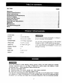
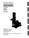
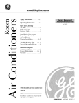
Owner's Manual
CRRFTSMRN°
Bench Model
2/3 HP(Maximum Developed)
5 Speeds (540-3600 R,P.M.)
1/2 Inch Chuck
12-INCH DRILL PRESS
Model No.
137.219120
•
•
•
•
•
•
CAUTION:
Before using this Drill Press,
read this manual and follow
all its Safety Rules and
Operating Instructions.
Customer
Help
Safety Instructions
Installation
Operation
Maintenance
Parts List
Espa_ol
Line
1.800-843-1682
Sears, Roebuck
USA
Part No.137219120001
and Co., Hoffman
Estates,
IL 60179
SECTION
PAGE
Warranty
...........................
Product Specifications
................
Safety Instructions
...................
Accessories
and Attachments
..........
Carton Contents .....................
Know Your Drill Press .................
Glossary of Terms
...................
Assembly and Adjustments
............
Operation
...............................................
Maintenance
.............................................
Troubleshooting
guide .....................................
Parts ...................................................
CHUCK SIZE
SPEEDS
.........
!20V, 50 HZ, 6 AMPS,
HORSEPOWER
2/3 HP (Max. Develo_3ed)
........
.........
............
°°°°=l
=°
..2
°o°oo.o.o°°°.°°o°°°o
°°
OI°°°Q
°°
,,3
,°°o°oo°°°,°o,°o,Jo°
°°
=°_=°
°l
.,6
°oo°,°°°°o.oo°o°o,°o
°°
°°=°°
ng
°,6
=°'°_°
oo
•
o°o°°oo°°°,°..oo°,l,
°°
,Jo°,°°oo°°o°,oo°°o,
°°
lloo°
=o°,l,°°,ooill,,,mlm
Qm
°ll==
oo
OOJ°°
,gql=,°
=
,OOo°,,
11
mi,w,a
118
•
m i_
...10
.... 16
.... 20
.... 21
....
22
To avoid electrical hazards, fire hazards, or damage to
the tool. use proper circuit protection.
Your drill press is wired at the factory for 120V operation
Connect to a 120V, !5 AMP branch circuit and use a
15 AMP time delay fuse or circuit breaker. To avoid shod
or fire, replace power cord immediately if it is worn, cut or
damaged in any way.
10-5/t6" x 8-2!/32"
TABLE TILT ...........
THROAT
=°oJl°°l°
°°
5 (540-3,600 RPM)
MOTOR ..............
SPINDLE TRAVEL
°n
.ooo,.oooo°o,.,,o°,o
I/2"
.............
TABLE SIZE
..2
°.,o.,o,,°,..=,,,,=,
45 o RIGHT OR LEFT
.....
2-3/8"
_"
BASE SIZE ...........
14-3/8" x 8-1/4"
HEIGHT .............
37-3/32"
Some dust created by power sanding, saw=ng, grinding, drilling, and other construction activities
contains
chemicals
known [to the State of California] to cause cancer, birth defects or other
reproductive
harm.
Some examples of these chemicals are:
•
Lead from lead-based paints.
•
Crystalline
silica from bricks, cement and other masonry products.
•
Arsenic and chromium from chemically-treated
lumber.
Your risk from these exposures varies, depending on how often you do this type of work. To reduce
your exposure
to these chemicals:work
in a well ventilated area, and work with approved safety
eauipment,
such as those dust masks that are specially designed to ,filter out microscopic particles.
2
GENERAL SAFETY INSTRUCTIONS
14.REMOVE
ADJUSTING KEYS AND WRENCHES.
From the habit of checking to see that keys and
adjusting wrenches are removed from the tool before
turning "ON".
BEFORE USING THE DRILL PRESS
Safety is a combination of common sense, staying alert
and knowing how to use your drill press.
15. NEVER LEAVE TOOL RUNNING UNATTENDED.
TURNTHE POWER "OFF". Don't leave the tool until
it comes to a complete stop.
To avoid mistakes that could cause serious injury, do not
plug the drill press in until you have read and understood
the following:
16. NEVER STAND ON TOOL. Serious injui'y could occur
if the tool is tipped or if the cutting tool is unintentionally
contacted.
1.
READ and become familiar with this entire instruction
manual. LEARN the tool's applications, limitations, and
possible hazards,
17. DON'T OVERREACH. Keep proper footing and
balance at all times.
2.
KEEP GUARDS IN PLACE and in working order.
3.
DON'T USE IN A DANGEROUS ENVIRONMENT.
Don't use power tools in damp or wet locations, or
expose them to rain. Keep work area well lighted.
18. MAINTAIN TOOLS WITH CARE. Keep tools sharp
and clean for best and safest performance. Follow
instructions for lubricating and changing accessories.
4.
DO NOT use power tools in the presence of flammable
liquids or gases.
5.
KEEP WORK AREA CLEAN. Cluttered areas and
benches invite accidents.
6.
KEEP CHILDREN AWAY. All visitorsshould be kept at
a safe distance from the work area.
7.
19. CHECK FOR DAMAGED PARTS. Before further use of
the tool, a guard or other part that is damaged should
be carefully checked to determine that it will operate
properly and perform its intended function. Check for
alignment of moving parts, binding of moving parts,
breakage of parts, mounting, and any other conditions
that may affect its operation. A guard or other part that
is damaged should be properly repaired or replaced.
20. MAKE WORKSHOP KID PROOF with padlocks, master
switches, or by removing starter keys.
DON'T FORCE THE TOOL. It will do the job better
and safer at the rate for which it was designed.
8.
USE THE RIGHT TOOL. Don't force tool or the
attachment to do a job for which it was not designed.
9,
WEAR PROPER APPAREL. DO NOT wear loose
clothing, gloves, neckties, rings, bracelets, or other
jewelry which may get caught in moving parts.
Nonslip footwear is recommended. Wear protective
hair covering to contain long hair.
21. DO NOT operate the tool if you are under the influence
of any drugs, alcohol or medication that could affect
your ability to use the tool properly.
22. Dust generated from certain materials can be
hazardous to your health. Always operate the drill
press in a well-ventilated area and provide for proper
dust removal. Use dust collection systems whenever
possible.
23. ALWAYS WEAR EYE
PROTECTION. Any drill press
can throw foreign objects into
the eyes which could cause
permanent eye damage.
ALWAYS wear Safety Goggles
(not glasses) that comply with
ANSI safety standard Z87.1. Everyday eyeglasses
have only impact-resistant lenses. They ARE NOT
safety glasses. Safety Goggles are available at Sears.
NOTE: Glasses or goggles not in compliance with
ANSI Z87.1 could seriously hurt you when they break.
10. WEAR A FACE MASK OR DUST MASK.
Drilling operation produces dust.
11. DISCONNECTTOOLS before servicing, and when
changing accessories, such as blades, bits, cutters,
and the like.
12. REDUCETHE RISK OF UNINTENTIONAL STARTING.
Make sure the switch is in "OFF" position before
plugging in.
13. USE RECOMMENDED ACCESSORIES. Consult the
owner's manual for the recommended accessories.
The use of improper accessories may cause risk of
injury to persons.
SAVE THESE INSTRUCTIONS
3
14. SECURE WORK. Use clamps or a vise to hold the
work when practical. It's safer than using your hand
and it frees both hands to operate tool.
SPECIFIC SAFETY INSTRUCTIONS
FOR THE DRILL PRESS
15. WHEN using a drill press vise, always fasten to the
table.
For your own safety, do not try to use your drill press
or plug it in until it is completely assembled and installed
according to the instructions, and until you have read and
understood this instruction manual:
1.
2.
3.
17. SECURELY LOCK THE HEAD and table support to
the column, and the table to the table support before
operating the drill press.
18. NEVER turn your drill press on before clearing the
table of all objects (tools, scraps of wood, etc.)
THIS DRILL PRESS is intended for use in dry
conditions, indoor use only.
WEAR EYE PROTECTION. USE face or dust mask
along with safety goggles if drilling operation is dusty.
USE ear protectors, especially during extended periods
of operation.
DO NOT wear gloves, neckties, or loose clothing.
5.
DO NOT try to drill material too small to be securely
held.
7.
tightened before drilling.
YOUR DRILL PRESS MUST BE BOLTED securely"
to a workbench. In addition, if there is any tendency
for your drill press to move during certain operations,
bolt the workbench to the floor.
4.
6.
16. MAKE SURE all clamps and locks are firmly
19. BEFORE STARTING the operation, jog the motor
switch to make sure the drill bit does not wobble or
vibrate.
20. LETTHE SPINDLE REACH FULL SPEED before
starting to drill. If your drill press makes an unfamiliar
noise or if it vibrates excessively, stop immediately,
turn the drill press off and unplug. Do not restart until
the problem is corrected.
21. DO NOT perform layout assembly or set up work on
the table while the drill press is in operation.
ALWAYS keep hands out of the path of a drill bit.
Avoid awkward hand positions where a sudden slip
could cause your hand to move into the drill bit.
22. USE RECOMMENDED SPEED for drillaccessory and
workpiece material. SEE INSTRUCTIONS that come
with the accessory.
DO NOT install ol use any drill bit that exceeds
!75 mm (7") in length or extends 150 mm (6") below
the chuck jaws. They can suddenly bend outward or
break.
8.
DO NOT USE wire wheels, muter bits, shaper cutters,
circle (fly) cutters, or rotary planers on this drill press.
9.
WHEN cutting a large piece of material make sure it
is fully supported at the table height.
23. WHEN DRILLING large diameter holes, clamp the
workpiece firmly to the table. Otherwise, the bit may
grab and spin the workpiece at high speed. DO NOT
USE fly cutters or multiple-part hole cutters, as they
can come apart or become unbalanced in use.
24. MAKE SURE the spindle has come to a complete
stop before touching the workpiece.
10. OO NOT perform any operation freehand. ALWAYS
hold the workpiece firmly against the table so it will
not rock or twist. Use clamps or a vise for unstable
workpieces.
25. TO AVOID INJURY from accidental starting, always
turn the switch "OFF" and unplug the drill press before
installing or removing any accessory or attachment
or making any adjustment.
11. MAKE SURE there are no nails or foreign objects in
the part of the workpiece to be drilled.
26. KEEP GUARDS IN PLACE and in working order.
27. USE ONLY SELF-EJECTING TYPE CHUCK KEY as
provided with the drill press.
12. CLAMP WORKPIECE OR BRACE against the left
side of the column to prevent rotation. If it is too short
or the table is tilted, clamp solidly to the table and
use the fence provided.
13. IFTHE WORKPIECE overhangs the table such that
it will fall or tip if not held, clamp it to the table or
provide auxiliary support.
SAVE THESE INSTRUCTIONS
4
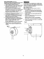
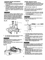
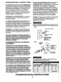
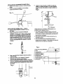
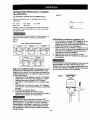
GROUNDINGINSTRUCTIONS
This tool is intended for use on a circuit that has a
receptacle like the one illustrated in FIGURE A.
FIGURE A shows a 3-prong electrical plug and receptacle
that has a grounding conductor. If a properly grounded
receptacle is not available, an adapter (FIGURE B) can
be used to temporarily connect this plug to a 2-contact
ungrounded receptacle. The adapter (FIGURE B) has a
rigid lug extending from it that MUST be connected to a
permanent earth ground, such as a properly grounded
receptacle box. The Canadian Electrical Code prohibits
the use of adapters.
INTHE EVENT OF A MALFUNCTION OR BREAKDOWN,
grounding provides a path of least resistance for electric
current and reduces the risk of electric shock. This tool
is equipped with an electric cord that has an equipment
grounding conductor and a grounding plug. The plug
MUST be plugged into a matching receptacle that is
properly installed and grounded in accordance with ALL
local codes and ordinances.
DO NOT MODIFYTHE PLUG PROVIDED. If it will not fit the
CAUTION: tn all cases, make certain the receptacle in
question is properly grounded. If you are not sure have a
certified electrician check the receptacle.
receptacle, have the proper receptacle installed by a
qualified electrician.
IMPROPER CONNECTION of the equipment grounding
conductor can result in risk of electric shock. The
conductor with the green insulation (with or without yellow
stripes) is the equipment grounding conductor. If repair
or replacement of the electric cord or plug is necessary,
DO NOT connect the equipment grounding conductor to
a live terminal.
This drill press is for indoor use only. Do not expose to
rain or use in damp locations.
Fig. A
3-Prong Plug
CHECK with a qualified electrician or service personnel if
you do not completely understandthe groundinginstructions,
or if you are not sure the tool is properly grounded.
USE ONLY 3-WIRE EXTENSION CORDS THAT HAVE
3-PRONG GROUNDING PLUGS AND 3-POLE
RECEPTACLES THAT ACCEPT THE TOOL'S PLUG.
REPAIR OR REPLACE DAMAGED OR WORN CORD
IMMEDIATELY.
).,
_-
Ground,n_ Prong
_
/
Properly Grounded
3-Prong Receptacle
Fig. B
Grounding Lug
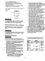
GUIDELINES
FOR EXTENSION
CORDS
Make sure your extension cord is in good condition.
When using an extension cord, be sure to use one heavy
enough to carry the current your product will draw. An
undersized cord will cause a drop in line voltage resulting
in loss of power and overheating. The table below shows
the correct size to use according to cord length and.
nameplate ampere rating. If in doubt, use the next heavier
gauge. The smaller the gauge number, the heavier the cord.
Be sure your extension cord is properly wired and in
good condition. Always replace a damaged extension
cord or have it repaired by a qualified person before
using it. Protect your extension cords from sharp objects,
excessive heat and damp or wet areas.
-- Make Sure This
is Connected to a
Known Ground
"" 2-Prong
Receptacle
Adapter
/
This tool must be grounded while in use to protect the
operator from electrical shock.
viI I _ I ht,l l j Ltl[_*f:ll[t1:11
;[O] :1 [:l:a I :ll _I_',1Ill _.[l(e]
:| e_.11r__ll,t,vl.
(when using 120 volts only)
Use a separate electrical circuit for your tools. This circuit
must not be less than #12 wire and should be protected
with a 15 Amp time lag fuse. Before connecting the motor
to the power line, make sure the switch is in the "OFF"
position and the electric current is rated the same as the
current stamped on the motor nameplate. Running at a
Jowervoltage will damage the motor.
SAVE THESE
Ampere Rating
25'
50'
100'
150'
0
6
18
16
16
14
6
10
18
16
14
12
10
12
16
16
14
12
12
16
14
12
Not recommended
INSTRUCTIONS
5
I Total length of cord in feet
morethan notmorethan
AVAILABLE
ACCESSORIES
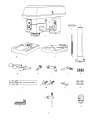
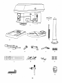
UNPACKING
CONTENTS
AND CHECKING
T!Ylv/_,1
t,:l_ll_[,_
Use only accessories recommended for this drill press.
Follow instructions that accompany accessories. Use of
improper accessories may cause hazards.
Visit your Sears Hardware Department or see the Sears
Power and Hand Tool Catalog for the following
accessories:
•
Drill bits
Hold-Down and Guide
Drill Press Vises
•
Clamping Kit
If any part is missing or damaged, do not plug the drill
press in until the missing or damaged part is replaced,
and assembly is complete.
Carefully unpack the drill press and all its parts, and
compare against the illustration below.
To protect the drill press from moisture, a protective
coating has been applied to the machined surfaces.
Remove this coating with a soft cloth moistened with
kerosene or WD-40.
To avoid fire or toxic reaction, never use gasoline,
naphtha, acetone, lacquer thinner or similar highly
volatile solvents to clean the drill press.
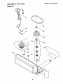
TABLE OF LOOSE PARTS
Use only accessories designed for this drill press to
avoid injury from thrown broken parts or workpieces.
Do not use any accessory unless you have completely
read the instruction or owner's manual for that accessory.
ITEM
DESCRIPTION
A.
B.
C.
D.
E.
F.
Head assembly
Base
Table
Column assembly
Collar
Rack
1
1
1
1
1
1
G.
H.
I.
J.
K.
L.
M.
N.
O.
P.
Loose parts bag:
Feed handles
Worm gear
Crank handle
Lock handle
Hex bolts
Fence assembly
Triangle knobs
Wing nuts
Washers
Hex keys
3
1
1
1
4
1
2
2
4
2
Box:
Q.
R.
Chuck key
Chuck
QUANTITY
F
G
H
L
I
M
J
N
P
Q
7
K
0
R
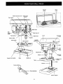
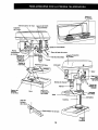
Spindle
pulley
Depth scale stop nuts
Motor
pulley
Depth scale
pointer
Cord clamp
Belt
tension
knob
, rod
Feed spring
Depth stop
Head lock
Cover
;to
/
Column collar
(
/
Bevel scale
Table support
screw
_.
elt
Head lock
screw
Support lock handle
Base
Bevel lock
----_Table
handle
Table
Rack
I
Fence backstop
Fence end_
Column support
crank
BASE- Supports the drill press. For additional stability,
holes are provided in the base to bolt the drill press to
the floor. (See "Specific Safety Instructions for Drill Presses".)
DRILL ON/OFF SWITCH - Has locking feature. This
feature is intended to help prevent unauthorized and
possible hazardous use by children and others. Insert the
key into the switch to turn the drill press on.
BACKUP MATERIAL - A piece of scrap wood placed
between the workpiece and table. The backup board
prevents wood in the workpiece from splintering when the
drill passes through the backside of the workpiece. It also
prevents drilling into the table top.
DRILLING SPEED - Changed by placing the belt in any
of the steps (grooves) in the pulleys. See the Spindle
Speed Chart inside the belt guard.
BELT GUARD ASSEMBLY - Covers the pulleys and belt
during operation of the ddll press.
FEED HANDLE - Moves the chuck up or down. If
necessary, one or two of the handles may be removed
whenever the workpiece is of such unusual shape that it
interferes with the handles.
BELT TENSION - Refer to the "Assembly" Section,
"Installing and Tensioning Belt."
BELT TENSION KNOB - Tightening the knob locks
the motor bracket support maintaining correct belt distance
and tension.
BEVEL SCALE - Shows the degree of table tilt for bevel
operations. The scale is mounted on the side of the arm.
CHUCK - Holds the drill bit or other recommended
accessory to perform desired operations.
CHUCK KEY -A self-ejecting chuck key which will pop
out of the chuck when you let go of it. This action is
designed to help prevent throwing of the chuck key from
the chuck when the power is turned "ON". Do not use
any other key as a substitute;order a new one if damaged
or lost.
FENCE - Attaches to the table to align the workpiece or
for fast repetitive drilling.Removable. Remove fence when
it interferes with other drill press accessories.
HEAD LOCKS -Locks the head to the column. ALWAYS
lock the head in place while operating the drill press.
RACK - Combines with gear mechanism to provide easy
elevation of the table by the hand operated table crank.
REVOLUTION PER MINUTE (R.P.M.) - The number of
turns completed by a spinning object in one minute.
SPINDLE SPEED -The
R.P.M. of the spindle.
SPRING CAP - Adjusts quill spring tension.
TABLE - Provides working surface to support workpiece.
COLUMN - Connects the head, table, and base on a
one-piece tube for easy alignment and movement.
TABLE BEVEL LOCK - Locks the table in any position
from 0 °- 45 °.
COLUMN COLLAR - Holds the rack to the column.
Rack remains movable in the collar to permit table
support movements.
TABLE CRANK HANDLE - Elevates and lowers table.
Turn clockwise to elevate table. Support lock must be
released before operating crank.
COLUMN SUPPORT - Supports the column, guides the
rack and provides mounting holes for column to base.
DEPTH SCALE - Indicates depth of hole being drillecl
DEPTH SCALE POINTER - Indicates the drilling depth
by pointing to the depth scale.
DEPTH SCALE STOP NUTS - Locks the depth scale to
selected depth.
DRILL BIT - The cutting tool used in the drill press to
make holes in a workpiece.
TABLE SUPPORT LOCK -Tightening locks the table
support to the column. Always have it locked in place
while operating the drill press.
TABLE SUPPORT - Rides on the column to support the
table.
WORKPIECE
- Material being drilled.
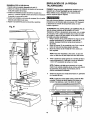
ASSEMBLY
INSTRUCTIONS
For your own safety, never connect plug to power source
outlet until all assembly and adjustment steps are
completed, and you have read and understood the safety
and operating instructions.
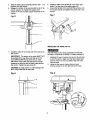
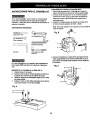
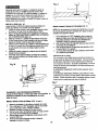
TABLE TO COLUMN ASSEMBLY (FIG. B THROUGH F)
1. Locate the worm gear, table crank, and table support
lock handle from the loose parts bag.
2. Insert the worm gear (1) into the table crank handle
hole (2) from inside the table support (3). Make sure
the worm gear (1) meshes with the inside gear.
3. Insert the table support lock handle (4) into the hole
at the rear of the table support. Tighten.
NOTE: Table removed from support in illustration for
clarity.
Fig. B
Slotted screwdriver
_
1
8" & 10" Adjustable wrenches
Combination wrench
Combination square
L I ] T_I I I I I I I I
Framing square
Socket wrench
with 23 mm. socket
4.
The Drill Press is very heavy and MUST be lifted with the
help of 2 PEOPLE OR MORE, to safely assemble it.
COLUMN SUPPORTTO BASE (FIG. A)
1. Position base (1) on floor.
2. Place column (2) on base, aligning holes in column
support with holes in base.
3. Locate four long hex bolts (3) from loose parts bag.
4. Place a bolt in each hole through the column
support and the base. Tighten with an edjust_ble
wrench.
Fig. A
2
Place the rack (5) in position inside the table support(3),
making sure the worm gear (1) on the inside of the
table support is engaged with the teeth of the rack.
Fig. C
3 !
,
6.
Slide the table support assembly with the rack (3,5)
together onto the column.
Engage the bottom of the rack (6) with the lip of the
column support (6). Tighten the support lock
handle (4) to lock the table support assembly to the
column.
8.
9.
Install the table crank handle (9) to the worm gear
shaft (1) on the side of the table support (3).
Line up the fiat side of the shaft with the set screw (10)
in the crank handle and tighten the screw with a hex
wrench.
Fig. F
Fig. D
4
3
5
6
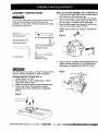
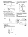
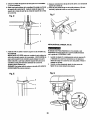
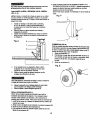
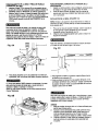
INSTALLING THE HEAD (FIG. G)
7,
Install the collar (7) to the top end of the rack (5) on
the column.
IMPORTANT: The bottom of the collar MUST NOT
be pushed all the way down onto the top of the
rack. MAKE SURE the top of the rack is under
the bottom of the collar and that there is enough
clearance to allow the rack to freely rotate around
the column. Tighten the set screw (8).
The Drill Press is very heavy and MUST be lifted with
the help of 2 PEOPLE OR MORE, to safely assemble it.
1
2,
Carefully lift head (1) above the column (2) and slide
it onto the column. Make sure the head slides down
over the column as far as possible. Align the head
with the base.
Using the hex wrench, tighten the two head
lock set screws (3) on the right side of the head.
CAUTION: To avoid column or collar damage, DO
NOT OVERTIGHTEN the set screw.
Fig. G
Fig. E
11
INSTALLING
FEEDHANDLES(FIG.H)
1.
2.
6.
Locate three feed handles in the loose parts bag.
Screw the feed handles (1) into the threaded holes (2)
in the hub (3). Tighten.
Using a rubber mallet, plastic-tipped hammer, or a
block of wood and a hammer, firmly tap the chuck
upward into position on the spindle shaft.
Fig. K
Fig. H
_
_
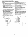
INSTALLING THE CHUCK (FIG. I, J and K)
1. Clean out the tapered hole in the chuck (1) with a
clean cloth.
2.
Clean tapered surfaces on the spindle (2).
CAUTION: Make sure there are no foreign particles
sticking to the surfaces. The slightest piece of dirt on
any of these surfaces wilt prevent the chuck from
seating properly. This will cause the drill chuck and
bit to wobble. If tapered hole is extremely dirty, use acleaning solvent.
MOUNTING DRILL PRESSTOWORK SURFACE (FIG. L)
1. If mounting the drill press to a workbench, a solid
wood bench is preferred over a plywood board, to
reduce noise and vibration.
2. Holes should be pre-drilled through the supporting
surface.
3. The hardware to mount this drill press is NOT
supplied with the tool. The hardware as shown in
the illustration should be used:
Fig. L
Fig. I
3.
4.
5.
Lower the spindle (2) by turning the feed handles (3)
counterclockwise.
Push the chuck up onto the spindle (2).
Tap gently to ensure seat.
Open the jaws of the chuck (1) by rotating the chuck
sleeve clockwise. To prevent damage, make sure the
jaws are completely receded into the chuck.
I
1.
2.
Drill press base
Bolt
3.
4.
5.
6.
Flat washer
(-Rubber washer |
Worksurface
|
Flat washer
7.
8.
Lockwasher
Hex nut
9.
Jam nut
_
_
II
II
IJ
]
5
Fig. J
12
I
I
FENCE ASSEMBLY (RG, M)
1. Determine the desired location for the fence (1).
2. Align the mounting holes of the fence over the table
top slots. '
3. Place a washer (2) on the threaded end of the knob (3).
Insert the knob through the mounting hole of the fence
and the table slot.
4. Place a washer and winG nut (4) on the knob from
under the table.
5. Repeat for the other knob and tighten.
Fig. M
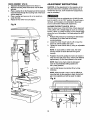
ADJUSTMENT
INSTRUCTIONS
CAUTION: All the adjustments for the operation of the
drill press have been completed at the factory. Due to
normal wear and use, some occasional readjustments
may be necessary.
V_rI_,_{_I_ [e
To avoid injury from an accidental start, ALWAYS make
sure the sw_tch is in the "OFF" position, the switch key is
removed, and the plug is not connected to the power
source outlet before making belt adjustments.
ALIGNING THE BELT PULLEYS (FIG. N)
Open the head cover of the Drill Press. Check alignment
of the pulleys with a straight edge (5) such as a framing
square, a level, or a piece of wood, Lay the straight edge
across the top of the pulleys. If all three pulleys are NOT
aligned:
1.. Release belt pressure by loosening the belt tension
lock knobs (2) on either side of the head,
counterclockwise.
2. Loosen the motor mount nuts (3). Lift or lower the
motor (4) until the pulleys are in line.
3. Tighten the motor mount nuts (3) using an adjustable
wrench.
NOTE: To avoid rattles or other noise, the motor
housing should not touch the lower belt guard
housing.
4.
Retighten the belt by pulling the motor (4) toward or
away from the drill press head, until the belt deflects
approximately 1/2 inch when pressed in the center.
NOTE: Refer to the chart inside the belt guard
cover for recommended ddlling speeds and
belt / pulley positions.
5.
Lock the belt tension lock knobs (2) by turning
clockwise.
NOTE: When the belt is new, it may be difficult to
move the belt, As the machine is used, the belt will
gain more elasticity and will be easier to adjust.
Fig. N
13
5.
To prevent personal injury,always disconnect the plug from
the power source when making any adjustments.
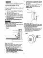
SQUARINGTABLETO
HEAD
6.
(FIG. O, P)
NOTE: The table and support has a predrilled hole with a
locking pin inserted for locking the table to a predetermined
0 ° horizontal position. It must be loosened to change the
angle of the table.
1.
2.
3.
4.
5.
7.
Fig. P
6
Insert a 1/4", or larger diameter, precision ground
steel rod (1), approximately 3" long, into the chuck (2).
Tighten the chuck jaws.
Raise table to working height and lock.
Using the combination square (3), place one edge
flat on the table, and align the other edge vertically
beside the rod (1).
(Figure P) If an adjustment is necessary, TIGHTEN
the nut (4) on the looking pin clockwise to RELEASE
it from the table support.
Loosen the large hex head bevel locking bolt (5).
To prevent injury, be sure to hold the table & table arm
assembly, so it will not swivel or tilt.
6.
To return the table to its original position, loosen the
bevel locking bolt (5). Realign the bevel scale (6) to
the 0_ position.
Return nut (4) on locking pin to the OUTSIDE END
OF THREADS. Gently tap lockingpin until it is seated
in the hole. Finger tighten nut (4).
NOTE: The table has been removed from the
illustration for clarity.
Align the square to the rod by rotating the table until
the square and rod are in line.
Retighten the large hex bolt (5).
Fig. O
2
SPINDLE/QUILL (RG. Q)
Rotate the feed handles counterclockwiseto lower spindle
to its lowest position. Hand support the spindle securely
and move it back and forth around its axis.
If there is too much play, do the following:
1. Loosen lock nut (1).
2. Turn the screw (2) clockwiseto eliminate the play, but
without obstructing the upward movement of the
spindle. (A little play in the spindle is normal.)
3. Tighten the lock nut (1).
1
Fig. Q
3
BEVEL SCALE
(FIG. P)
NOTE: The bevel scale has been included to'measure
approximate bevel angles. If precision is necessary,
a square or other measuring tool should be used to
position the table. To use the bevel scale (6):
1. TIGHTEN the nut (4) on the locking pin clockwise to
RELEASE it from the table support.
2. Loosen the large flex head bevel locking bolt (5).
3. Tilt the table, aligning the desired angle measurement
to the zero line oppositethe scale (6).
4. Tighten the bevel locking bolt. (5).
14
QUILL RETURN SPRING (FIG. Q, R)
The quillreturn spring may need adjustment if the tension
causes the quill to return too rapidly or too slowly,
1. Lower the table for additional clearance.
2.
3.
_vlvl-1_l L'ql_(
To avoid injury from an accidental start, ALWAYS make
sure the switch is in the =OFF" position, the switch key is
removed, and the plug is not connected to the power source
outlet before making belt adjustments.
Place a pcrewdr_ver in the lower front notch (1) of the
spring cap (2). Hold it in place while loosening and
removing only the outer jam nut (3).
With the screwdriver still engaged in the notch,
loosen the inner nut (4) just until the notch (5)
disengages from the boss (6) on the drill press head.
BELTTENSION (FIG. S)
Make sure pulleys are aligned properly as shown in
Figure O on page 13.
1. To unlock the belt tension, loosen the belt tension
lock knobs (1) on both sides of the drill press head.
2. Move the motor (2) toward the front of the drill press
to loosen the belt.
CAUTION: DO NOT REMOVETHIS INNER NUT,
because the spring will forcibly unwind.
4.
5.
6.
Carefully turn the spring cap (2) counterclockwise with
the screwdriver, engaging the next notch.
Lower the quill to the lowest position by rotating the
feed handle in a counterclockwise direction while
holding the spring cap (2) in position.
If the quill moves up and down as easily as you
desire, tighten the standard nut (4) with the adjustable
wrench. If too loose, repeat steps 2 through 5 to
tighten. If too tight, reverse steps 4 and 5.
3.
Position the belt on the correct pulley steps for the
desired speed.
Pull the motor away from the drill press head until
the belt is properly tensioned.
4.
NOTE: Belt tension is correct if the belt deflects
approximately 1/2 inch when pressed at the center.
5.
Tighten the belt tension lock knobs (1) on both sides
of the drill press head.
DO NOT OVERTIGHTEN and restdct quill movement.
7.
Fig. S
Replace the jam nut (3) and tighten against the
,tandard nut (4) to prevent the standard nut from
eversmg.
Fig. R
1
J
3
4
15
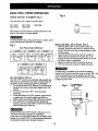
BASIC DRILL PRESS OPERATIONS
SPEEDS AND BELT PLACEMENT
Fig. U
(FIG. T)
This drill press has 5 speeds, as listed below:
540 RPM
2610 RPM
880 RPM
3600 RPM
1600RPM
See inside of the belt guard for specific placement of the
belts on the pulleys to change speeds.
To avoid possible injury, keep guard closed, in place, and in
proper working order while tool is in operation.
Fig. T
Belt I Puiley Position-RPM Chart
540 RPM
880 RPM
2610 RPM
1600 RPM
3600 RPM
ON / OFF SWITCH (FIG. U)
The "ON / OFF' switch has a removable, yellow plastic key.
With the key removed from the switch, unauthorized and
hazardous use by children and others is minimized.
1. To turn the drillpress "ON", insert key (1) intothe slot of
the switch (2), and move the switch upward to the "ON"
position.
2. To turn the drill press "OFF", move the switch
downward.
3. To lock the switch in the "OFF position, grasp the end,
or yellow part, of the switchtoggle, and pull it out.
4. With the switch key removed, the switchwill not operate.
5. If the switch key is removed while the ddll press is
running, it can be turned "OFF" but cannot be restarted
without inserting the switch key.
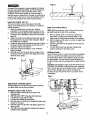
INSTALLING DRILL BIT IN CHUCK (FIG. V)
1. With the switch "OFF" and the yellow switch key
removed, open the chuck jaws (1) using the chuck
key (2). Turn the chuck key counterclockwise to open
the chuck jaws.
2. Insert the drill bit (3) into the chuck far enough to
obtain maximum gripping by the jaws, but not far
enough to touch the spiral grooves (flutes) of the drill
bit when the jaws are tightened.
3. Make sure that the drill is centered in the chuck.
4. Turn the chuck key clockwise to tighten the jaws.
To avoid injury or accident by the chuck key ejecting
forcibly from the chuck when the power is turned "ON", use
only the self-ejecting chuck key supplied with this drill
press. Always recheck and remove the chuck key before
turning the power "ON".
Fig. V
Always lock the switch "OFF" when the drill press is not in
use. Remove the key and keep it in a safe place.
In the event of a power failure, blown fuse, or tripped circuit
breaker,turn the switch"OFF' and remove the key,preventing
an accidental startup when the power comes on.
16
Fig. X
1
To prevent the workpiece or backup material from being
torn from your hands while drilling,you MUST positionthe
workpiece against the LEFT side of the column. If the
workpiece or the backup material is not long enough to
reach the column, clamp them to the table, or use the fence
provided with the drill press to brace the workpiece. Failure
to secure the workpiece could result in personal injury.
USINGTHE FENCE (FIG. W)
The fence provides a way of accurately and quickly
setting up the workpiece for more precision or repetitive
drilling operations.
1. Using the centerpunch or sharp nail, make an
indentation in the workpiece where you want to drill.
2. Lower the drill bit to align with the indentation on the
workpiece. See =HOLDING A DRILLING LOCATION"
page 19.
3. Loosen the knobs (1) and slide the fence back stop (2)
firmly against the long side of the workpiece. Tighten
the knobs when in position.
4. Loosen the wing nut (3) and slide the end stop (4) along
the fence until it is firmly against the left side of the
workpiece. Tighten the wing nut.
5. Check the accuracy by drilling a scrap workpiece.
Adjust if needed.
6. Hold with your hand or clamp the top surface of the
workpiece firmly to prevent it from liftingoff the table
when the bit is raised.
Fig, W
2
Depth scale method (FIG. Y)
NOTE: With the chuck up, the tip of the drill bit must be
just slightly above the top of the workpiece.
!.
2.
3.
4.
With the switch "OFF', turn the feed handle until
the pointer (7) points to the desired depth on the
depth scale (4). Hold the feed handles in that position.
Spin the lower nut (3) down to contact the depth stop
lug (6) on the head.
Spin the upper stop nut (5) against the lower stop nut
and tighten.
The and drill bit will now stop after traveling the
distance selected on the depth scale.
Drilling a hole
Using a center punch or a sharp nail, dent the workpiece
where you want the hole. Before turning the switch on,
bring the drill bit down to the workpiece, lining it up with
the hole location. Turn the switch on and pull down on
the feed handles with only enough effort to allow the drill
to cut.
FEEDING TOO SLOWLY might cause the drill bit to turn.
FEEDING TOO RAPIDLY might stop the motor, cause the
belt or drill to slip, tear the workpiece loose, or break the
drill bit. When drilling metal, it will be necessary to
lubricate the tip of the drill bit with oil to prevent it from
overheating.
Fig. Y
DRILLING TO A SPECIFIC DEPTH
Drilling a blind hole (not all the way through workpiece)
to a given depth can be done two ways:
Workplece method (FIG. X and Y)
1. Mark the depth of the hole on the side of the
workpiece (1).
2. With the switch "OFF", bdng the drillbit (2) down
until the tip is even with the mark.
3. Hold the feed handle at th!s position.
4. Spin the lower nut (3) down to contact the depth stop
lug (6) on the head.
5. Spin the upper nut (5) down and tighten against the
lower nut. (3)
6. The drill bit will now stop after traveling the distance
marked on the workpiece.
17
REMOVING CHUCK (FIG. Z)
1. With the switch =OFF", open the jaws of the chuck as
wide as possible by turningthe chuck counterclockwise.
2. Tap the chuck (1) lightly with a plastic tipped hammer
at the top of chuck, until the chuck releases.
b. Whenever possible, position the WORKPIECE to
contact the left side of the column.If it is too short
or the table is tilted, use the fence provided or
clamp solidly to the table, using the table slots.
c. When using a drill press vise, always fasten it to
the table.
d. Never do any work freehand (hand-holding the
workpiece rather than supporting it on the table),
except when polishing.
e. Securely lock the head and table supportto the
column, and the table to the table support, before
operating the drill press.
f. " Never move the head or the table while the tool
is running.
g. Before starting an operation,log the motor switch
to make sure the drill or other cutting tool does
not wobble or cause vibration,
h. If a workpiece overhangs the table so it will fall
or tip if not held, clamp it to the table .or provide
auxiliary support.
i. Use the fence provided or other fixtures for
unusual operations to adequately hold, guide,
and position workpiece.
j.
Use the SPINDLE SPEED recommended for the
specific operation and workplace material. Check
the panel on the inside pulley cover or the chart
below for drilling speed information.
For accessories, refer to the instructionsprovided
with each accessory.
NOTE: Place one hand below the chuck to catch it when
it 'fallsout.
Fig. Z
To avoid injury from an accidental start, ALWAYS make
sure the switch is in the "OFP position, the switch key is
removed, and the plug is not connected to the power
source outlet before removing or installing the chuck.
BASIC OPERATION
INSTRUCTIONS
To get the best results and minimize the likelihood of
personal injury, follow these instructionsfor operating your
drill press.
5.
6.
For your own safety, always observe the safety
INSTRUCTIONS listed here and on pages 3, 4, and 5
of the instruction manual.
7.
YOUR PROTECTION
_I:_
-'_ II_[e_
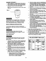
DRILLING SPEED TABLE (rpm)
To avoid being pulled into the power tool, do not wear
loose clothing, gloves, neckties, or jewelry. Always tie
beck long hair.
1.
2.
3.
4.
ff any part of your drill press is missing, malfunctioning,
damaged or broken, stop operation immediately until
that part is propedy repaired or replaced.
Never place your fingers in a position where they
could contact the drill bit or other cutting tool. The
workpiece may unexpectedly shift, or your hand
could slip.
To avoid injury from parts thrown by the spring, foUow
instructionsexactly when adjusting the springtension
of the quill.
To prevent the workpiece from being torn from your
hands, thrown, spun by the to01, or shattered, always
properly support your workpiece as follows:
a.
Never climb on the drill press tablet it could break or
pull the entire drill press down on you.
Turn the motor switch "OFF", and put away the switch
key when leaving the drill press.
To avoid injury from thrown work or tool contact, do
not perform layout, assembly, or set up work on the
table while the cutting tool is rotating.
Always position BACKUP MATERIAL (used
beneath workpiece) so that it contacts the left side
of the column, or use the fence provided and
clamp to brace a smaller workplece.
18
DrillBit
Diam.
Material
(Inches)
Wood
1/16
3600
Alum.,Zlnc,Bnm
3600
1/8
36OO
2610
1600
3/16
1/4
2610
5/16
88O
3/8
1/2
Iron,Steel
1600
2610
88O
540
POSITIONING THE TABLE AND WORKPIECE
(FIGURE AA and BB)
1. Lock the table (1) to the column (2) at a position so
the tip of the dnll bit (3) is Justabove the top of the
workpiece (4).
2. ALWAYS place a BACK-UP MATERIAL (scrap wood)
on the table beneath the workpiece. This will prevent
splintering or heavy burring on the underside of the
workpiece. To keep the back-up material from spinning
out of control, it MUST contact the LEFT side of the
column.
HOLDING A DRILLING LOCATION
1. Using a centerpunch or sharp nail, make an
indentation in the workplace where you want the hole.
2. Using the feed handles, bring the drill down to align
with the indentation before turning the drill "ON".
TILTING THE TABLE (FIGURE CC)
NOTE: The table and support (t) has a predrilled hole
with a locking pin inserted for locking the table into a
predetermined 0° horizontal position.
1.
To prevent the workplace or backup material from being
torn from your hands while drilling, you MUST position it
against the left side of the column. If the workpiece or
the backup material iS not long enough to reach the
column use the fence provided with the drill press to
brace the workpiece, or clamp it to the table. Failure to
do this could result in personal injury.
2.
To use the table in a bevel (tilted) position, TIGHTEN
the nut (2) on the locking pin clockwise to RELEASE
it from the table support.
Loosen the large hex head bevel locking bolt (3).
To prevent injury, be sure to hold the table & table arm
assembly, so it will not swivel or tilt.
.,Fig. AA
Fig. CC
/-
,m,,==_,_==_m
,mm_mmma_m='
I
k3
1
2
3.
3.
For small pieces that cannot be clamped to the table,
use a drill press vise (optional accessory).
4.
_Y/zI_iI_
The drill pf'ess vise MUST be clamped or bolted tq the
table to avoid injury from a spinning workplace, or
damaged vise or bit parts.
Remove the drill press fence when it interferes with other
drill press accessories.
Fig. BB
5.
Tilt the table, aligningthe desired angle measurement
to the zero line opposite the scale (4). Tighten the bevel
locking bolt.
To return the table to its original position, loosen the
bevel locking bolt,(3). Realign the bevel scale (4) to
the 0 ° position.
Loosen the nut (2) on the locking pin to the OUTSIDE
END OF THREADS. Gently tap the locking pin until it
is seated in the hole. Finger tighten the nut.
To avoid injury from spinning work or tool breakage, always
clamp workpiece and backup material securely to the
table before operating the drill press with the table tilted,
FEEDING
1. Pull down the feed handles with only eno_ugheffort to
allow the drill bit to cut.
2. Feeding too slowly might cause the drill bit to burn.
Feeding too rapidly might stop the motor, cause the
belt or ddU to slip, or tear the workplece loose and
break the drill bit.
3. When drilling metal, it may be necessary to lubricate
the drill bit tip with motor oil, to prevent burning the tip.
19
MAINTAINING
YOUR DRILL PRESS
To avoid shock or fire hazard, if the power cord is worn
or cut in any way, have it replaced immediately.
For your own safety, turn the switch OFF and remove the
plug from the power source outlet before maintaining or
lubricating your drill press.
LUBRICATION
Frequently blow out using an air compressor or dust
vacuum, any dust that accumulates inside the motor.
All of the drill press ball bearings are packed with grease
at the factory. They require no further lubrication.
A coat of automotive" paste wax applied to the table and
column will help to keep the surfaces clean.
Periodically lubricate the gear and rack, table elevation
mechanism of the spindle and the rack (teeth) of the quill.
2O
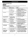
TROUBLESHOOTING
GUIDE
To avoid, injury from an accidental start, turn the switch OFF and always remove the plug from the power source
before making any adjustments.
• Consult your local Sears Service Center if for any reason the motor will not run.
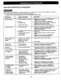
PROBLEM
PROBABLE CAUSE
Noisy operation.
1.
REMEDY
Incorrect belt tension.
1. Adjust tension. See Section
"ASSEMBLY - TENSIONING BELT"
2. "Lubricate spindle. See Section "LUBRICATION".
3. Check tightness of retaining nut'on pulley, and
tighten if necessary.
4. Tighten set screw in motor pulley.
2. Dry spindle.
3. Loose spindle pulley.
4. Loose motor pulley.
Drill bit burns.
1. Incorrect speed.
2.
3.
4.
5.
Run out of drill bit point drilled hole not round,
Chips not coming out of hole.
Dull drill bit.
Feeding too slowly.
Not lubricated.
1. Change speed. See Section "BASIC DRILL
PRESS OPERATION - SPINDLE SPEEDS"
2. Retract drill frequently to clear chips.
3. Resharpen drift bit.
4. Feed fast enough - allow drill to cut. •
5. Lubricate drill. See Section "BASIC DRILL
PRESS OPERATION - FEEDING"
1. Hard grain in wood or
lengths of cutting flutes
and/or angles not equal.
2. Bent drill bit.
1. Resharpen drill bit correctly.
Wood splinters on
underside,
1. No backup material
under workpiece.
1. Use cackup material. See Section
"BASIC DRILL PRESS OPERATION".
Workpiece torn
loose from hand.
1. Not supported or
clamped properly.
1. Support workpiece or clamp it. See Section
"BASIC DRILL PRESS OPERATION".
Drill bit binds in workpiece.
1. Workpiece pinching drill bit,
or excessive feed pressure.
2. Improper belt tension.
1. Support workpiece or clamp it. See Section
"BASIC DRILL PRESS OPERATION".
2. Adjust tension. See Section
"ASSEMBLY - TENSIONING BELT."
Excessive drill bit
runout or wobble.
1. Bent drill bit.
2. Worn bearings.
3. Drill bit not properly
installed in chuck.
4. Chuck not properly installed.
1. Use a straight drill bit.
2. Replace bearings.
3. Install drill properly. See Section "BASIC DRILL
PRESS OPERATION" and "ASSEMBLY".
4. Install chuck properly. See Section
"ASSEMBLY -INSTALLING THE CHUCK".
Quill returns
1. Spring has improper tension.
too slow or too fast.
1. Adjust spring tension. See Section "ASSEMBLYADJUSTMENTS - QUILL RETURN SPRING".
Chuck will not stay
attached to spindle,
It falls off when
trying to install,
1. Dirt, grease, or oil on the
tapered inside surface of
chuck or on the spindle's
tapered surface.
1. Using a household detergent, clean the
tapered surface of the chuck and spindle to
remove all dirt, grease and oil. See Section
"ASSEMBLY - INSTALLING THE CHUCK"
21
2. Replace drill bit.
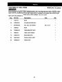
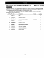
CRAFTSMAN 12" DRILL PRESS
MODEL NO, 137.2191,20
When servicing use only CRAFTSMAN replacement parts. Use of any other parts may create a HAZARD or cause
product damage. Any attempt to repair or replace electrical parts on this Table Saw may create a HAZARD unless
repair is done by a qualified service technician. Repair service is available at your nearest Sears Service Center.
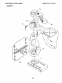
Always order by PART NUMBER, not by key number
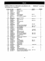
PARTS UST FOR SCHEMATIC A
Key
Part No.
Description
1
10300105
BASE
1
2A
10300202A2.
COLUMN HOLDER ASS'Y
1
3
2601BBDAg0
HEX. SOC. SET SCREW
4
13902202
RACK
1
10300603A11
TABLE BRACKET ASS'Y
1
10602003
TABLE LOCK HANDLE
1
7A
10302301A1
RACK RING ASS'Y
1
8A
10601009A3
CRANK HANDLE ASS'Y
1
9A
10838202A1
FENCE ASS_
1
5A
6
Size
22
M8x1.25-25
Qty
4
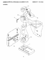
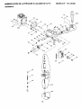
CRAFTSMAN12" DRILL PRESS
MODEL NO. 137.219120
SCHEMATIC
A
?A
I
"gA
23
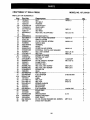
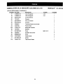
CRAFTSMAN 12" DRILL PRESS
MODEL NO. 137.219120
PARTS LIST FOR SCHEMATIC B
Kf0y
11
12
13A
14A
15
16
17
18
19
Part
No.
10518401
10301004
10201201
2135CNO132
10305602A1
2701FBD106
10361701
2602BBLA27
N/A
2898D08G24
S ize
M1Ox1.5
Description
NUT
SET BOLT
POINTER
CHUCK ASS'Y
QUILL ASS'Y
HEX NUT
SET RING
HEX. SOC. HD,CAP BOLT
M6X1,0
M5 x 0.8-16
aty
2
1
1
1
1
1
1
1
ROCKER SWITCH
...........
"2"_
...........
26t_,lMr_oE]:f...............
"(3RTR'E
TTRO_;RI3";9"¢RItW ....................................
I_Y:1"6"-"_2
......................................
":P.
..........
21
22
23
24
25
26
27
28
29
10312704
2668BBDA24
10308805
2805U5HN16
10384902
2668BZDA23
2504MZC005
10305401
2701FBD113
SWITCH COVER
CR. RE. PAN HD. SCREW
SWITCH BOX
TERMINAL
SCALE
CR.RE.PAN HD SCREW
EXTERNAL TOOTH LOCK WASHER
QUILL SET SCREW
HEX. NUT
M5x0.8-12
M5x0.8-8
M8x1.25-18
M8x1.25
1
3
1
1
1
2
2
1
1
...........
_ ...........
"_'_'0"_'_0i_
........................
"_PRIR_3RET;_II_ER
................
i.........................................................................................
t ..........
31A
32
33
34
35
36
37
38
39
10305001A2
2701QZD611_
2668BBDA24
10808301
10604204
2603BBLA52
2603BBLA52
2536MBE623
13902503
SPRING CAP ASS'Y
HEX. NUT
CR. RE. PAN HD. SCREW
CLAMP-CORD
SHIFTER BOLT
HEX. SOC. SET SCREW
HEX. SOC. SET SCREW
SPRING PIN
HEAD
I/2x20UNF
M8 x 0.8-12
M8x1.25-8
M8x1.25-8
1
2
1
1
2
2
1
2
1
...........
;41_
...........
2_0"=I'I_B_;_ ...............
FIE'XTR'D'_i31LT
...........................................................................................................
"_.........
41
42A
43
44
45
46
47
48
49
2501NBDN27
8220A21104
13916403
2701FBD113
2701FBD110
2502ABC410
10303401
10303202
2501NNVN11
FLAT WASHER
MOTOR
LABEL
HEX. NUT
HEX. NUT
SPRING WASHER
MOTOR BASE
MOTOR ROD
FLAT WASHER
5116x718-5164
M8xl.25
M10xl.5
1/4x3/4-3/16
8
1
1
4
1
2
1
1
4
...........
_ ...........
"_'_'0"_1502
........................
"_i3";_[It"R'll_
......................................................................................................
_..........
51
52
53A
54A
55
56
10316208
2658MZDU36
10304402A1
10303825A1
2641BBDA39
10611201
LABEL
DRIVE SCREW
HANDLE BAR ASS'Y
FEED SHAFT
CR. RE. ROUND WASHER HD. SCREW
CHUCK KEY HOLDER
24
2.3-5
M6"1.0-12
1
4
1
1
1
1
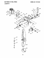
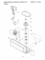
CRAFTSMAN12" DRILL PRESS
MODEL NO. 137.219120
SCHEMATIC
B
45
54A
35
11
it0
25
MODEL NO. 137.2t912C
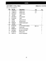
CRAFTSMAN 12" DRILL PRESS
PARTS UST FOR SCHEMATIC C
Key
Part
No.
Description
Size
Qty
57
2138MBL704
WRENCH HEX
4-64
1
58
2138MBL703
WRENCH HEX
3-57
1
59
2807BY06H2
POWER CABLE
1
60
13916905
LABEL
1
61
2801ABRF04
STRAIN RELIEF
2
62
2572ARK340
V-BELT
1
63
10306901
PULLEY SET NUT
1
6_4
10307005
SPINDLE PULLEY
1
10306512A1
DRIVING SLEEVE ASS_'
1
LABEL
1
65A
66
13916602
67
2641BBDA39
CR. RE, ROUND HD.SCREW
68
10208302
CLAMP-CORD
4
69
2668BBDA23
CR. RE, PAN HD,SCREW
4
70A
10307908A2
MOTOR PULLEY ASS'Y
1
71
2571MNC307
PARALLEL KEY
1
72A
10409011A3
PULLEY COVER ASS'Y
1
26
M6X1.0-12
4
MODEI.NO. 137.219120
CRAFTSMAN12" DRILL.PRESS
SCHEMATIC
C
59
64
71
70A
65A
69
J
68
72A
61
60
27
For repair of major brand appliances in your own home...
no matter who made it, no matter who sold it!
1,800-4-MY-HOME s"Anytime, day or night
(1-800-469-4663)
www.sears.com
To bring in products such as vacuums, lawn equipment and electronics
for rePair, cell for the location of your nearest Sears Parts & Repair Center
1.800-488-1222
_.,
dayorn_ht
www.sears.com
For the replacement parts, accessories and owner's manuals
that you need to do-it-yourself, call Sears PartsDirect =_ !
1-800-366-PART
6a.m.-11p.m.
CST,
(1-800-366-7278)
7 days a week
www.sears.com/partsdirect
To purchase or inquire about a Sears Service Agreement:
1-800-827-6655
7 a.rn.'- 5 p.m. CST, Mon. - Sat.
.Pard pedir servicio de reparaclbn a domidlio,
y pard ordenar piezas con entmga a domicilio:
1-888-SU-HOGAR
Au Canada pour sewics en fran_ais:
1.877.LE.FOYER
=.
TM
{1-888-784-6427)
SEARS
o,,,,,.,.=_,,.
=,
HomeCentrar
®.,.,=.,,
,,,-.-,'-,,.-_ ,,=..,.P-=_..,
=.
J
® Matca Registrada_ Mama de F_brk_ de Seam,Roebu_ and CO.
FULL ONEyEAR WARRANTY
If _ i_uCt failsduetOa defe<_in materi_d_ v,_kmansh_owi_-_ o_e_u
_ re_t_ it _ ofch_ge.
_
_
_
_ _.
_
ConUtcta Sears Ser_e C_mUvfo_"
m_.
If G_isl_ct
pufcJuse.
i.Jusedfor€ommerdaior rentalpurpo_s, thiswamu_ _
'n_ *tmtr¢/g_,,es you_
_an=,
onlyf_' g0 dlys fromlhe _
legaldg_s_end_ou may mo h=_ oG_"rklt_ts
wNchvsry _'om_
_
_ s_
Roeb_mk and Co., DepL 817 WA, Hoffrmm Eatates, IL eO179
11/200(
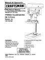
Manual de Operacibn
CRRFTSMRN°
2/3HP (Potencia M_xima)
5 Velocidades (540-3600 R.P.M.)
Mandril de 1/2 Pulg.
PRENSA TALADRADORA
DE 12 PULG.
Modelo No.
137,219120
CUIDADO:
/
Antes de usar esta Prensa
Taladradora leer este manual
y seguir todas las Reglas de
Seguridad e instrucciones
de Operaci6n
.0
Instrucciones de Seguridad
Instalaci6n
Operaci6n
Mantenimiento
Lista de Partes
Tel6fono
para
Ayuda al Cliente
1.800-843-1682
Sears, Roebuck
USA
Part No.137219120001
and
Co., Hoffman
Estates,
IL 60179
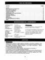
SECCION
PAGINA
Garantia ............................................................................
Especificaciones de la Herramienta ......................................................
Instrucciones de Seguridad ...........................................................
Accesorios y Aditamentos .............................................................
Contenido de la Caja .................................................................
Familiarizarse con la Prensa Taladradora .................................................
Glosario de Terminos .................................................................
Ensamblaje y Regulacibn ..............................................................
Operaci6n .................................................................
Mantenimiento .....................................................................
Guia para Diagn6stico de Problemas ................
"...................................
Partes : ............................................................................
TAMANO DEL MANDRIL
VELOC]DADES ........
MOTOR ........
'......
CABALLAJE ...........
LUZ INCORPORADA ......
TAMA_IO DE LA MESA
INCL]NACION
DE LA MESA ............
DESPLAZAMIENTO
DEL EJE ...............
CUELLO ...............
TAMAI_IODE LA BASE ....
ALTURA .............
.1/2"(13ram)
5 (540-3,600 RPM)
120V._0 HZ, 6 AMFS.
2/3 HP(Desarroflo Maxi.)
60 Wars (Maximo)
(No tnduye el foco)
10-5/16" X 8-2!/32"
(26.2 cmx 22 cm)
450 A LA OERECHAC IZQUJEROA
).........
30
30
:31
:34
:34
:36
37
38
43
.48
49
50
Usar protecci6n adecuada en el circuito para evitar rles_os
e!e_ncos, de incenaio o _ah,os a la herramiema.
La Prensa T_Jaaraaoraesta cabteadaen la fa._ncapara cperar a
120V. Conectarla _ un circuito de 120V.15 Amps. y usar un
merrup[or ce c:rcuito o fusibie de ,'etardode 15 Amos. S; el
cora6n elec:rico estuvlese gas{ado, cortado o dar_aao,=n
cualquier form& reempiazarto de Inmediatopara witar
eleotrocuci0no Incendio.
•2-3/8" (6 cm)
.6" (15.2cm)
14-3/8" X 8-1/4" (36.6cm X 21cm)
37-3/32"/94.2cm)
Alogunos polvos creados por el lijado mec_mico, el aserrado, el esmedtado, el taladrado y otras
actividades de construccibn
contienen sustancias quimicas conocidas [pot le Estado de California]
como agentes
cancerigenos,
defectos
¢ongenitos y otros daSos reproductores.
Algunos
ejemplos de estas sustancias quimicas son:
•
El plomo de las pinturas a base de plomo,
•
El silice cristalino de los ladriltos y ¢emento y otros productos de mamposteria,
y
•
El arsenico y el ¢romo de la madera tratada quimicamente.
.El riesgo resultante de la exposition
varia segQn la frecuencia con que se realiza este tipo de
trabajo. Para reducir la exposition a esta sustancias quimicas: trabaje en un lugar bien ventiiado y
realice el trabajo utilizando
el equipamiento
apropiado, tal como las re&scares para el oplvo
especialmente
diser_ados para eliminar las pa.,'ticulas minQscutas.
30
INSTRUCCIONES
SEGURIDAD
GENERALES
14. RETIRAR LAS HERRAMIENTAS DE
REGULACI6N. Formarseel habitode verificarqua las
herramientasy lasIlavesde regulaci6nhayansidoretirades
del taladroantesde activado.
DE
ANTES DE USARLAPRENSATALADRADORA
La seguridad es una combinaci6n de sentido comdn, mantenerse
alerta y saber como usar la PrensaTaladradora.
Para evitar errores que puedancausarlesiones serias,no
conectar el taladro hasta haber leido y entandido Io siguiente:
"16. NUNCA PARARSESOBRE LA HERRAMIENTA.Pueden
ocurnrlesionessedassi la herramientase volteao si se
entraen contactocon el taladro.
LEER y familiarizarse con todoeste manual de
instrucciones. ENTENDER las aplisaciones, limitacionesy
riesgos posib_es,
1.
.
17. NO ESTIRARSEMAS ALI,.ADEL ALCANCE DE UNO.
Mantener losdos pies bienapoyadosy el equilibroen
todomomento.
MANTENER LOS PROTECTORESEN POSICI(_Ny en
buanas condiciones de operacibn.
3,
NO OPERAR EN AMBIENTES PEMGROSOS. No usar la
herramienta en lugares h0medos, mojadoso expuestosa la
Iluvia.Mantenerel area de trabajobien Uuminada.
4.
NO USAR herramiantaseldctficasen la presencia de
Iiquidoso gases inflamables.
5.
MANTENER EL AREA DETRABAJO UMPIA. Lasdreas y
mesas de trabajocongestionadasinvitana qua ocurran
accidantes.
6.
MANTENER A LOS NINOS ALEJADOS. To<loslos
visitantesdeben mantenerse a una distancia seguradel
area de trabajo.
7.
NO FORZAR LA HERRAMIENTA,La herramientahard un
mejor trabajoy mas segurousandolas61oen la brma para
la que fue disefiada.
8.
9.
15. NUNCA DEJAR DESATENDIDAUNA HERRAMIENTA
ELI_CTRICACUANDO ESTE FUNCIONANDO.
DESCONECTARLA FUENTE DE ENERGIA.No alejarse
del lugar hasta que la herramientase haya detenidopor
completo.
18. DAR MANTENIMIENTOCUIDADOSOA LAS
HERRAMIENTAS.Parauna operaci6n mejor, mas seguray
rapida, mantener tasherramientasafiladesy limpias.Seguir
las instrucoiones
para la lubdcaci6ny carnbiode accesorios.
19. INSPECClONARPARA DETECTARPIEZAS DANADAS,
Antesde usarla harramienta,siempreinspeccionarla
_idadosamante pare cercioraressi losprotectoresu otras
piezasestdndeSadasy determinarsiva a operar
adecuadamenteen el usoque se le va a dar.Inspeccionar
si hay piezasmoviblesdesatineadaso atrasadas;partes
rotas o mal montadas,y cualquierotracondiciSnque pueaa
afectarla operaci6nde la herrarnienta.
Si un protectoro
cuaJquier
otrapiezaestuvtesedefiada deberepararse
adecuadamenteo reemplazarse.
20. ASEGURARSEQUE LOS NItrOS NOTENGAN ACCESO
AL TALLER DETRABAJO. Usarcandados,interruptores
maestros y quitar las Ilavesde activaci6n.
USAR LA HERRAMIENTAADECUADA,No forzarla
herramienta al hacer un trabajo para el cual no ha sido
dise_ada.
21. NO operar la herramienta bajo la influenciade drogas,
alcohol o medicamentosque pudiesenafectarla habilidad
para operar la herramientaadecuadamente.
USAR ROPAADECUADA. NO usarropasuelta,guantes,
corbatas,anillos,brazaletes ni joyasque pusdanquedar
atrapadosan laspiezas moviblesde la herramienta.Se
recomienda usar salzado antiresbalante.Usarprendas de
sadeza para cubrir o contener el cabeUolargo.
22. Et polvogeneradepor ciertosmaterialespuede ser noctvo
para la salud.Siempreoperarla PrensaTaladradoraen un
area bien ventilada para eliminarel polvo.Cuando fuese
posib_e,usar sistemas recolectoresde polvo.
!0. USAR UNA MASCARA PARA LA CARA O PARAPOLVO.
Los trabajos con taladro producan polvo.
11. DESCONECTARLAS HERRAMIENTASantes de cambiade
accesori0stalescomo: hojas, brocas,cortadoresy similares.
12. REDUCIR EL RIESGO DE ARRANQUESACCIDENTALES.
Cerciorarse que el interruptorde energfaeste en la posici6n
"OFF" (Apagado)antes de enchu_r la herramientaa la
corrienteeldctrica..
13. USAR ACCESORIOS RECOMENDADOS.Consultar con
e! manualdel operador.paradeterminar cualessonlos
acossodosrecomendados.El usode accesodos
inapropiadospuedeser peligrosoy ganerarriesgode
lesionespersonales.
23. SIEMPREUSAR
PROTECCI(_NPARALOS OJOS.
Cualquier PrensaTaladradora
puedearrojarcuerposextrafiosa
los ojosqua puedancausar
dafiospermanentesa la vista.
SIEMPRE usarGafasde
Segurided(no anteojos) que cumplancon la norma 7_87.1
de ANSI. Los anteojos de usodiado S61otienen lentes
resistantesa los impactos,estos NO SON galas de
seguridad,l.as Galas de Seguridad puedenadquirirseen
Sears. NORA: Los anteojos o galas qua no cumplencon la
norma Z87.1 de ANSI pueden causar dafios serios al
romperse.
CONSERVAR ESTAS INSTRUCClONES
31
REGLASDE SEGURIDADESPEC{FICAS
PARALA PRENSATALADRADORA
Por su propia seguddad,no ttatar de usar la PrensaTaladradorani
enchufarlahasta que est_ completamente-ensamblada
e instalada
de acuerdocon las istrucciones,y hasta haber leido y entendido
este manualde instrucclones:
1.
2.
3.
4.
5.
6.
7.
8.
9.
LA PRENSA TALADRADORA DEBE ESTAR EMPERNADA en forma segura al banco de trabajo.
Adicionalmente, si hubiese la tendencia a que el
banco de trabajo Taladradora se mueva durante
ciertas operaciones, empernar ta prensa al piso.
ESTA PRENSATALADRADORAs61oes para usarse en
condicionessecas yen interiores.
USAR PROTECClON OCULAR, USARm&scaraprotectora
para la carao para polvosjunto congafasde seguridadsi
la operaci6ngenerapolvo.USARprotectoresde ofdo,
especialmenteduranteperiodoslargosde operaci6n.
NO usar guantes, corbatani ropasuelta.
NO intentartaladrar objetosque sean demasiado peque5os
como parafijarlos con sujetadores.
SIEMPRE mantener las manos fuera del camino de las
brocas. Evitar colocarlas manosen posicionesen las
cualesun resbal6ns_b_topuedahacerque las manos
entrenen contactocon la broca.
NO instalar ni usar brocas cuyolargo exceda 175 mm (7") o
que se proyecten 150 mm (6")por debajo de las quijadas
del mandril. Pueden doblarsesL_bitamentehacia afuera
o romperse.
NO USAR ruedasde alambre,brocas para buriladoras,
cuchillasformadoras, cortadoresde circulosnicepillos
giratoriosen esta PrensaTaladradora.
CUANDO se est_ taladrandouna pieza grande de material,
cerciorarse que est_ completamentesujeta a ta altura
de ta mesa.
14. RJAR LA PIEZA DE TRABAJO.Cuandofuesaprdctico,
usarsargentas o una prensapara sujetar1_piezade tmbajo.
Es rods saguro que usarla mano y deia librearnbasmanos
para operarla hermmienta.
15. AL USAR una prensa para taladro,siempresujetariaa
la mesa.
16. CERCIORARSEQUE todoslos elementosmecdnicos de
sujecionesten ajustadosflrrnemente.antes
de comenzar
a taladrar.
17. ASEGURAR EL CABEZAL CON EL SEGURO y sujetarel
soporte de la mesa a la columna, y la mesa al soporteantes
de operar la PrensaTatadradora.
18. NUNCA hacer funoionar la Prensa Taladradoraantes
de haber despejadotodo objetode la mesa (henamientas,
desechos de madera, etc.).
19. ANTES DE COMENZAR la operacibn,hanerfuncionar el
taladrobrevementea baja velocldedpara cerclorarseque no
se bamboleeo vibre.
20. PERMITIR QUE EL EJE ALCANCE SU VELOClDAD
M,_XIMAantes de comenzaraa taladrar,Si el taladrohace
atg,',nruidoque no sea familiaro vibraexcesivamente,
detenerel trabajoinmediatamente,apagarel taladroy
desenchufadode la corriente.No volverioa poneren
operacl6nhasta habercorregidoel problema.
21. NO realizar laboresde trazado,ansamblaje ni preparaci6n
sobrela mesa cuandola herramientaest_ en operaclbn.
22. USAR LA VELOCIDAD RECOMENDADApara el accesorio
y tipode materialde la piezaque se est_ tmbajando.VER
I_ASINSTRUCCIONESque vienencon el accosorio.
23. AL TALADRAR orificios de di_netm grande,fijarla pieza
de trabajocon sujetadoresen formafirme a la mesa.De
Io contrariola brocapuedeagarmrla piezaque se est_
trabajandey hacerlagimra granvelocldad.NO USAR
cuchillasde fresadorani elementosque taJadrenofifidos
m,',ltiplesporquepuedendesarmarseo desbalancearse
conel uso.
4,
10. NO realizar operaci6nalgunaa mano libre.SIEMPRE
sujetarla pieza que sa est_trabajandoenforrnaflrrne
contrala mesa paraque no se mueva o tuerza.Usar
sargentaso prensas si se taladranpiezas inestables.
11. CERCIORARSEque nohayanclavosni objetosextrahos
en la parte de la pieza que se va a taladrar.
12. RJAR LA PIEZA DETRABAJO CON SUJETADORES
contrael lade izquierdode la columnaparaevitarque gire.
Si fuesemuycortao si la mesa de la herramientaestuviese
inclinada,sujetariafirmemente a la mesa y usarla
guiaprovista.
CERCIORARSEque el eje se hayadetenido completamante
antesde entraren _cto
con la pieza de tmbajo.
25. PARAEVITAR LESlONESdebidasa arranques
accidentales,siemprecolocarel interruptoren la posici6nde
"OFF" (Apagado)y desanchufarel taladroantesde instalaro
retiraraccesorioso de realizarcualquierajusteo regulaclbn.
26. MANTENER LOS PROTECTORESEN POSICl0N y en
buenascondicionesde operaci6n.
27. SOLO USAR UNA LLAVEDEL MANDRILTIPO AUTO
EXPULSANTEcomo la provistaconla Prensa
Taladradora.
13. St LA PIEZA DETRABAJO se proyectafuera de la mesa
de formatal que se caigao inclinesi no estuviesesujeta,
sujetartaa la mesa o proveerun soporteauxiliar,
CONSERVAR ESTAS INSTRUCCIONES
32
INSTRUCCIONES PAPA LA CONEXI(_N A TIERRA
EN EL EVENTO DE UNA FALLAO MAL FUNCIONAMIENTO,
la conexi6na tierraproveeuna via de menor resistenciaparela
corrienteel_'trica, reduciendoasi el fiesgo de choqueel_-tfico.
Esta herramientaest_ equipedacon un cord6n el_ctfico que
tJeneun conductor para conexi6na tJerray tambi_ncon un
enchufecon espigapare el mismotin.El enchufeDEBE
conectarseen untomacomenteque le hagajuego y que este
debidamenteinstaladoy conectado a tJerrade acuerdocon
TODOS los ccktigosy ordenanzaslocales.
NO MODIFICAR EL ENCHUFE PROVISTO.Si no entraen et
tomacordente,hacer que un etectricista
califlcadeinstaleun
tomacorrienteadecuado.
LA CONEXlON INADECUADADEL CONDUCTORparetierra
de un equipopuedegenerarriesgode choqueel#,._"ico.
El
conductorcon form aislanteverde (cono sin rayasamarillas)es
el conductorpareconexi6n a tJerra.Si el cord6nel_.'tricoo et
enchuferequierenraeparaciones
o reemplazo,NO conectarel
conductor para tierradesequipoa unterminalvivo.
Esta herramientaest_ disefiadapera usarseen un cimuitoque
tengaun tomacorriente
como el ilustradoen la FIGURAA.
La RGURA (A) muestraun enchufeelL_.--trico
y un tomacorriente
d_ 3 contactos, unode los cualeses un conductor pare
conexi6na tierra.Si no se disponede un tomacorfiente
con
conductorpareconex_na tierra,temporalmente
se puedeusar
un adaptador(FIGURAB) paraenchufarloen un tomacorfiente
de 2 contactossinconexi6n a tierra. El adaptador(RGURA B)
tiene un anillofigido que le sobresaley que DEBE conectarse
fisicamenteen forma permanente a tierra,telcomo ia caja de un
tornacorriente
debidamenteconectadoa tierra.ElC_ligo
Et_ctfico Canadienseprohibeel uso de estos adaptadores.
CUIDADO: En todoslos cases,cerciorarseque el tomacorriente
en cuestJ6nest_ adecuadamenteconectadoa tierra.Si no se
estuvieseseguro,hacerque un electficista
licenciado
inspeccioneel tomacorriente.
Esta PrensaTaladradoraes_ disefiadaunicarnentepara uso en
interiores.No exponedaala Iluvia ni usaria en lugares htimedos.
Fig. A
Enchufe
de 3 espigas
AVERIGUARcon un electdcistao personalde se_cio si se
tiene cualquierdudeen cuanloala conexi_ correcta a tierra
del equipo,o si lesinstrucciones para la conexi6na tierrano
est_ndares.
®
SOLO USAR CORDONES DE EXTENSION QUETENGAN
ENCHUFE DETRES ESPIGASY UNTOMACORRIENTEQUE
ACEPT1EEL ENCHUFE DE LA HERRAMIENTA.REPARARO
REEMPI.AZAR INMEDIATAMENTELOS CORDONES
DA_IADOSO GASTADOS.
_----_
RECOMENDACIONESPAPALOS CORDONES
DE EXTENSION
Cerciorarse que el cordbn de extensi6nest_ en buenas
condiciones.
AI usar un cordbn de extensi6n,corciorarseque
sea Io suficientemente
_]ruesopare conducirla cordente que la
herramientademandara.Un cord(_nsubdimensionado
causam
una cafda en el voltaje de la tfneacausandouna p_rcrldede
petencia y recalentamiento.La table que apareceen esta
pdgina muestralos calibrescorrectesde los cordonesseg_n
suextensibny el arnpe_e requerido per la herramientaque
aparace en la place. En ca.sode dude, user el siguientecalibre
m_.sgrueso.Cuanto menor el ndmero del calibre, mayor el
di_metmdel alambre.
CercJorarseque el cord6n de extensldn tenga los alambres
adecuados y que estden buenascondicionesel_'tricas.
Siempreresmplazarlos cordonesde extensi_ da_adoso
hacedesrepararper unapersonacalificada
antesde usades.
Protegerloscordonesde extensi6nde los objetosfilosos, del
caforo humedadexcesivay de las _ffeash_medeso mojadas.
Fig. B
_Tomacordente pare
enchufe
de3 espigas
debidamente
conectado
a tierra
_leOxPara
atierra
/
I_
"[_
I / | I__ ![ Cerciorarse
que
/
='ll
J
a
_"'_/'_'_
-J_'_J"_
_!
\
_
conexi6n a
Tomacorriente
Adaptador
de 2 contactos
rt_
Pareprotecci_ndel operadorcontrachoquesel_ctricos,esta
herramientadebe esterconectadaa tierm.
nlq,_! s i=i :l =11_
i i_i IA[el ii =11
I[OI.."tl_ldlq
:1oIOI_I=k,1o|=1=KsI =1__ [o)_|F:_L_ m
(S_
Usar un ramalde circuitoindependientepara _ta herramienta.
Este drcuitodebe ser d.eun elambra cuyocalibrenosea menor
a 12 y dede estarpmtegidoconun fusiblede retardode 15
Amp_.Antes de conectar el motorala Iinea de suministro
ekY_trico,
corciorarse que el interruptorest_ en la posici6nde
"OFF" (Apagado)y qua la cQrrienteel_-'tdcasea la indicadaan la
placede datesdel motor.Operarla herramientacon un voltaje
menor puededa_ar el motor.
Amperage
Especlficado
al user 120 voltios)
Lon_ltud total del ¢orddn en pies
25'
50'
100'
150'
m_de
_m_de
0
6
6
10
18
16
16
14
18
16
14
12
10
12
16
16
14
12
12
16
;14
12
no recomendado
CONSERVAR ESTAS INSTRUCClONES
33
ACCESORIOS
DESEMBALAJE
CONTENIDO
DISPONIBLES
S61ousar accesoriosrecomendadospara esta Prensa
Taladradora Seguir las instruccionesque acompafian a los
accesoriosEl uso de accesorios inadecuadospuede
generar riesgos
•
•
•
•
•
•
DEL
Si t&itasenpiezas o hubiesenpiezasda_adas, no enchufarla
PrensaTaladradorahasta conseguirlas piezas t<anteso de
reemplazar las dafiadas y hasta haber ¢ompletadeel ensambt&je
Visitarel Departamentode Ferreteda de la tiendaSears
mas cercana over el Cat&logode HerramientasEIL_tricas/
Neum_,ticasy Manualesde Sears para los siguientes
accesorios:
•
Y VERIFICACI6N
Desempaquetarcuidadosamente
la PrensaTatadradera
y todas
sus partes y vedficadascontrala relacionque est&a
continuaci6n.
Paraproteger ta PrensaTaladradoracontrala humedad,las
partes maquinadashan siderecubiertascon una capaprotectora
que se debe removercon un patiohumedecidoconkerosene
o WD-40
Brocas paraTaladro
Sujetadory Guia
Prensas para PrensaTaladradora
Juego de Mortaja y Espigapara Prensa
Taladradora
Juego de Sujetadores
Cincel y Brocastipo Mortaja y Espiga
TamboresLijadores
Ruedas Pulidorasde hasta 4" (10 cm) de
DiametroM_imo
Sierra para Orificiosde hasta 2-1/2" (6.35 cm)
Paraevitarinoendioso reaccionestbxicas,nuncausargasolina,
nafta, acetona,tinerparatacaso solventessimitaresde alta
volatilidadpara limpiarla PrensaTaladradora.
TABLE
ART
A.
B.
C.
D.
E.
F.
Paraevitarlesiones causadasporpiezas rotaso piezas de
trabajo rotasexpedidas,s61ousaraccesoriosrecomendados
paraesta PrensaTaladradora.
Sears puederecomendarotrosaccesorios no listadesen este
manuel Visitar la tienda Sears mas cercana o vet el Cat&logod_
HerramientasEl_ctricas/Neumdticasy Manualesde Sears
G,
Np usaraccesorioalgunoa menos de haber leido
completamenteel manualde instrucciones
u operacionde ese
accesorio
H.
I
J
K
L
M
N
O
P
Q;
R
34
OF LOOSE
PARTS
DESCRIPCI6N
Cabezal
Mesa
Base
Columna
Anillo
Cremallera
Botsacon piezas sueltas:
Manijasde Avarice
Manijadel Seguro
Manivela
PernosHexagonales
Gu{a
Pemo Perillade 3 At&tas
Btoque-T
Arandela
Uaves Hexagonales
Cu_na
W,_go
C_a:
I_lavedelMandril
Mandril
CANTIDAD
1
1
1
1
1
1
3
1
1
4
1
2
2
2
3
1
1
D
C
G
H
,
L
,
K
,.1
M
N
0!]
P
Q
35
0
Poleas de
las Correas
Tuerca Superior de Tope
Suletador
deLCordbn
Aguja de la escala
de profundidad
i de Profundidad
Manija
Tensionadon
de Coneas
Resorte del
Mecanismo
de Avance
de tope de avance
Cubierta Protectora
Tope de profundidad
la Co|umna
Escala de
Inclinacibn
Soporte de la Mesa
Interruptor
\
Segurode I
Manij
Tensionador
de Correa
Manijas de Avansa"
Pernos de
Fijaci6n del
Cabezal
Seguro del
Base
Soporte
oe Ja Mess
Seguro de
la Inclinacibn
de la Mesa
Manivela
de la Mesa
Mesa
Columna
Topedel
Extreme
de la Guia
TopePosteriorde la Gula
Soporte
del a
Columna
36
BASE- Soporta
la PrensaTaladradom.Paramayorestabilidad
VF:LOCIDADDETALADRADO - Se carnbiacolosandota corrsa
encualquierade las poleas.Ver la Tablade Velocidadesen la
parte intema de la cubierta protectorade las correas.
estdprovista de orificiosparaempemar la PrensaTaladradomal
piso.(Ver"InstnJccionesde SeguridadEspec_'flsas
para Prensas
Taladradoras').
MANIJAS DE AVANCE - Mueven el mandril hacia arriba y
abajo.Si fuese necosario,se pueden quitar una o dos rnanijas
cuandola piezade trabajosea de una forma taninusualque
interlieracon las manijas.
MATERIAL DE APOYO- Una piezade madera de desechoque
se colocaentrela pieza que sa trabajay la mesa. La madera de
apoyoevitaque se astillela maderaque sa taladracuandola
broca la atravieza.Tambienevitateladrarla supeffidede la
mesa,
GU|A - Se monta en la mesa y sirve para alinearla piezade
trabajoo para hacer perforacionesrepetitJvas
en forma rdpide.Es
desmontable.Sasarlacuandointe_era con losaccesoriosde la
PrensaTaladradora.
CUBIERTAPROTECTORA DE CORREAS - Cubre laspoleasy
correasduranteta operacidnde la PrensaTaladmdora.
TENSION DE LAS CORREAS - Refedrsealas secciones:
"Ensamblaje"• "lnstalaci6ny Tensi6nde Correas',
MANilA TENSIONADORA DE CORREAS - Girarla manija en
el sentidodel relojLoamtensionarla correay contrael sentidodel
relojpara elivlar la tensi6n.
SEGURO DE LA MANILATENSIONADORA DE CORREAS Ajustandolas manijassa fija el soportedel motory la manija
tenelonadoramanteniendo ta distanciay tensi6ncorrectade la
correa.
LLAVE DEL MANDRIL - Una Ilaveque se autoeyectadel
mandril cuandose le suelta.Esta acci6nestddise_fiada
para
evitarque la Navesalgadisparadadel mandril cuandose active
la herramienta.No usar IlavessubstJtutas.
Si sa deteriorao
pierde,ordenaruna Ilavenueva.
CREMALLERA - Funcionaen combinaci6n conel mecanismo
de engranajes.Sirve pare facilitar ia elevaci6nde la mesa
operando a mano la manivela de la mesa.
REVOLUCIONES POR MINUTO (R.RM.) - El n_mem de
vueltas completasque un objetogiratoriode en un minuto.
ESCALA DE INCUNACl6N DE LA MESA - Muestralos grades
de indinaci6nde la mesa paralos trabajosde pianoindinado.La
escelaestdmontadaa un costadodel brazo.
MANDRIL - Sujetala brocataladradorao cualquierotro
accesoriorecomendadopara reelizarlos tt-dbajos
desaados.
SEGUROS DEL CABEZAL - Fija el cabezalen la columna.
SIEMPRE lijar el cadezalen posici6ncon los sagut'oscuandesa
opere16PrensaTeladradora.
VELOClDAD DEL EJE - Las R.RM. del eje,
TAPA DEL RESORTE - Regula la tension del resorte de la
mort_ja,
SEGURO DEL SOPORTE DE LA MESA - AI ajustartoseguros
se ajustael soportede la mesa a la columna.Siempretenerlo
puestocuandosa operela PrensaTaladradera.
MESA - Provee una superfidede trabajopara apoyarla pieza
de trabajo.
COLUMNA - Es untuboque conectael cabezai,la mesa y la
base para facilitarsu alineamientoy mc_imiento.
COLLARiN DE LA COLUMNA - Sujeta la cremalleraa la
cotumna.La cremallerase mantienem6vilen el collarfnpara
permitirlos movimientos
del soportede la mesa.
SOPORTE DE LA COLUMNA - Soportala columna,guia 16
cremalleray proveeorificiospara montarla celumnaa
la base.
PERILLA DE SEGURO DE LA INCUNACI(_NDE LA MESA Fijala mesa en cualquierdngulode indinaci6n de 0°a 45°.
MANIVELA DE LA MESA - Sirve para subiry bajarla mesa.
Giradaen el sentidodel relojpara elevarla mesa.Debe soltarsa
el segurodel soporteantasde operala manivela.
TUERCAS DETOPE DE LA ESCALA DE PROFUNDIDADFijael eje a la profundidadsaleccionade.
SEGURO DE LA MESA - Fija la mesa en posic_ndespudsde
colosarlaen cualquierposicibn.
ESCALA DE PROFUNDIDAD- Indica la profundidaddel orificio
que se estdtaladrando.
SOPORTE DE LA MESA - Se desplazaen la columnapara
soportarel brazo de la mesay la mesa.
BROCA - La herramientaque sa usa en Is PrensaTaladradora
para hacer losortfidosen la piezade tmbajo.
INTERRUPTORDEL TALADRO -'riene un dispositivo
de
seguro.Este dispositivo
estddisafiadopardevitarel usono
autorizadoy posiblementepeUgrosopornifiosy otraspersonas.
Iosertarla I_ve en el interruptory girarlapara ponereltaladroen
operaci6n.
PIEZA DE TRABAJO - El materialque se teladra.
37.
Ens•mbl•je
INSTRUCCIONES PARA EL ENSAMBLAJE
Pot su propia seguridad,nuncaenchufaren el tomacorriente
hasta haber completadotodoslos pasos del ensamblajela
regulaci6n, y hasta haber leido y entendido las instruccionesde
segufidad y operaci6n.
de la columna • I• meu
(Fig. B • F)
1. Ubicarel eje de tomillosinfln,la manivelade la mesay el
segurodelsoportede la mesade la bolsade piezassueltas.
2. Introducirel eje de tomiUosinfln(1) en el oriflc_o
(2) par• la
manivel•de la mesa desdela parte interiordel soporte(3).
Asegurarsede que el eje detornitlosinflnengranecon el
engranajeinterior.
3. Introducirla manijadel segurodel soportede la mesa (4) en
el orificiode la parteposteriordel mismo. Ajustar.
Nora: Para mayordaridad, en la ilustracibnno se ha incluidoI•
mesa del soporte.
HERRAMIENTASNECESARIAS
Fig. B
_
1
Desarmador Piano
Llaveregu_able
de8"y 10"
Llave combinada
_.....
l E I !:;i',;ii:
I
....
_ i
[ ]
Escuadra
I
i
k i
!
i
:
W
Escuadra combinada
Llave ratchet con dado
de 23 mm
' La PrensaTpladradoraes muypesaday pardensamblarseen
lorma seguraDEBE levantarsecon la ayudade 2 personas o
m_s.
4. Colocarla ctemalleraen su lugardentrodel soporte(3) de la
mesa,esegur_ndesade que el eje de tomillosinfln(1) en la
parte interiordel soportequedeengranadocon los dientesde
la cmmallera.
Fig. C
SOPORTE DE LA COLUMNA A LA BASE (RG. A)
1. Colocarla base (1) en el piso.
2. Colocarla columna(2) en la basealineandolosorificiosen
el soportede la columnaconlos orificiosde la base.
3. Ubicarlos oJatropernoshexagonaleslargos(3) en la bolsa
conpiezas sueltas.
4. Colocarun pemo en cada orifidodel soportede la columna
y de la base. Ajustarcon una Ilaveregulable.
Fig. A
2
3
I
38
5. Colocarla unidadde soportede la mesajuntocon la cremallera 8. Instalela manivela (9) en el eje del tomillosinfln(1) en el ladodel
( 3, 5) en la columna,
soportede la mesa (3).
6. Hacerque la parte inferiorde la cremallera(5) encajeen el borde 9. Alineela parte planadel eje con el tom,in pdsionero(10) de la
del soportede la columna(6). Ajustela manija del saguro del
menivelay aprieteel tomillocon una ,ave hexagonal.
soportede la mesa (4) pare fljarla unideddel sol)odede la mesa
en la co(umna,
Fig. F
Fig. D
4
3
6
INSTALACIONDEL CABEZAL (FIG.G)
7. Instaleel anillo(7) sobreel extremosuperiorde la cremallera(5),
en la columna.
IMPORTANTE:NO DEBE meterporcompletola parte inferiordel
anillosobrele partesuperiorde la cremallera.ASEGURARSEde
que la partesuperiorde la cremalleraquededebajode la parte
inferiordel aniliny que haya suficienteespaciolibreparaque la
cremallerapuedagirarlibrementealrededor de la columna.
Aprleteet pemo _sionero (8).
CUIDADO: Pare evitardaf_arla columnao el anillo,NOAPRIETE
EXCESIVAMENTEel pemo pdsionero.
El cabezalde la PrensaTaladraderaes muy pesaclay para
ensamb/arseen forma seguraen la columnaDEBE levantarse
con la ayudede 2 PERSONASO M._S.
1.
2.
Levantarel cabezal(1) cuidadosamente
sobrelacolumna(2)
y deslizarlaen la columna.Cerciorarseque el sabezal se
deslicetan abajoen la columnacomosea posible.Alinearel
cabezalcon la base.
Usandouna,ave hexagonal,ajustarlosdos pernosde
fijacibn (3) en el lado derechodel cabezal.
Fig. G
Fig, E
5
1
39
|NSTALACIONDE LAS MANIJAS DE AVANCE(RG.H)
1. Ubicarlastresmanijas de avanceen la boI_. de piezas
sueltas.
2. Insertery enroscartas manijas(1) en losorificios
.
roscades
(2)ctetcubo(3).AjusWr.
Fig. H
_
3 /
INSTALACIONDEL MANDRIL (FIG. I, J and K)
1. Limp|atel orificioahusadoen el mandril(1) con un
paso
,m_.
2.
Usandoun mazo de cauchoo martillocon cabeza de
pl_co o un bloquede maderay un martil_o,
go_peado
levementehada arribahastaque enca)eenposicibnen
el eje.
FlCJ. K
Limpiar
Jassupe_ciesahusades
de4v_stago(2)
CUIDADO: Cerc_ommque no hayancuerpes
adheridosalas superficies.La partfculade tJerran_s
peque_ en estassuperf'_es evitardque el manddlse
asienteapropiedarnente.Estohar_ que d rnandritdet
taladroy _ broc.ase bard:_een. Si el or_ aht,mado
estuvieseextremadamente
sucio,.emplearun solvente
({mpi_dor.
COMO INSTALAR LA PRENSATALADRADORAA LA
SUPERFICIE DE TRABAJO.(FIG. L)
1. Si se instalala prensataladradorasobreuna mesade
trabajo,es prefer|hieuna mesa de madera macizaen lugar
de untablerode maderacontrachapada,para disminuirel
nivelde ruidoy de vibracibn.
2. Debe haberseperforadolosodficiospreviamenteen la
superficiede apoyo.
3. Con la herramiente,NO se suministralas piezasde
ferreter|a para su instalacibn.Debe utilizarse|as piezasde
ferreterfa comose muestraen la ilustmcibn:
Fig. I
Fig. L
I.
2.
3.
4,
,
Bajarel eje girandolas manijasde avance (3) contrael
sentiUo
delreloj.
4,
5,
Colocarel n_nddl (1) en e! v_L_tago(2). Golpeado
levementepare cerelorarseque se asJente.
Abdrlas mandibulasdel mandril(1) girandota mangadel
n_ndril en el sen_dodel reloj.Pareevitardefios, cerciorarse
que las rnand_ulasest6ncompletamentemtra_dasdentro
del mandril.
\
5
=_==¢====
.3
4O
I
Base de fa prensataladradora ,_J
Pemo
Arandelaplane
_[
Arandelade cauch_
G. Supe_cie de trabajo|
6. Arandefaplane.
[
7. Arande|ade presibn I
8. Tuercahexagonal Vi/
9.
Contratuerca
\
.
Fig, J
I
!
\_
I
I
REGULACION
DE LA PRENSA
ENSAMBLAJE DE LA GUIA (FIG. M)
TALADRADORA
1. Decidir cuSI es la posicibn deseada de la gula (1).
2 Alinear los orificios de instalacibn de la gula con las ranuras
CUIDADO:T_xloslos ajustesy regulaciones
necesar_aspara la
de la parte superior de la mesa.
operaci_h-I
de la PrensaTaladradoraban sidehechasen la
3. Colocar una arandela (2) sobre el extremo roscado de la
f_bdca. Debido a_use y desgastenormal,ocasionalmente
perilla (3). Introducir la perflla a trav/_sdel orificio de instalacibn podrfanrequefirsealgunosreajustes.
de la gula y la ranura de la mesa.
4. Colocar una arandela y una tuerca de mariposa (4) en la perilla,
desde la parte inferior de la mesa.
Para evitar lesiones debidas a un arranque accidental,SIEMPRE
5. Repetir el procedimiento para la otra periUay ajustarlas.
cerciorarsaque el interruptor este en la posici6n OFF (Apagado)
Fig. M
y desconectar et enchufe del tomacordenteantes de hacer
cualquier regulaci6n.
ALINEAMIENTODE I.AS POLEAS DE LAS CORREAS(FIG.N)
Abrirla cubierta protectorade las correasen la Prensa
Taladradora.Verificaret atinearniento
de laspoleas, con una regla
(5), escuadra,nivelo pedazode maderarecta.Colocar el horde
de la regla a Io largode la parte superiorde las poleas.Si todas
las poleasestuviesendesalineadas:
1. Ativiarla tensi6nde las correasaflojandolos segurosde las
manijastensionadoras(4) de correasa cada ladodel
cabezal,desenganchandolasmanijastensionadoras
(1)
de correas.
2. Aflojar1astuercas(2) de montajedel motor.Subiro bajarel
motor(3) hastaque las poleasqueden alineadas.
3. Ajustarlastuercas(2) de montaje del motor usandouna
llave regulable.
NOTA: Para evitar traqueteosy otros ruidos,el casco del
motor no debe tocar la parte infedor del cascodela correa.
4.
Volvera ajustarlas correasgirandoen el sentido del relojla
manijatensionadora(1), hastaque la correase deflexione
1.2 cm (1/2")al presionarla correaen el medio.
NOTA: Referirsea la tab_aque se encuentraen la parte
interior de la cubiertaprotectora de las correas,paraobtener
las posicionesde lasIx)leas recomendadas
para las
distintas velocidadesde taladrado.
5.
Ajuatar lossaguros de la manijatensionadora(4), girandolos
en elsentido
delreloj.
NOTA:Cuando las correasestdnnuevas,puedeserdiffcil
movedas.Conformese usala mdquina, las correasse
vo_verdnrnas eldsticasy serdnmasfdcilesde regular.
N
4
41
Pareevitarlesionespersonales,siempredesconectarel enchufe
del tomacorriente
antesde hasarcuelquierregulacion.
PARAPONER LA MESA A ESCUADRACON EL CABEZAL
(RG. O, P)
5. Volvera colocarla tuerca(4) en el pasadorde fijadbn,en el
EXTREMOEXTERIOR DE LA ROSCA. Golpearauavernerrt_el
pasadorde fijacibnhasteque quedeesentadoen elorificlo.
Ajustarla tuerca(4) con losdedos.
NOTA:Pare mayorcladdad,en la ilustracibn
nose hainduidola
mesa.
Fig. P
NOTA:El brazoy el soporte de la mesa ya vienenconun orificio
que treeinsertadoun tomilloparefijarla mesa en una posicidn
horizontalpredeterminadade 0°.Aflojarel tomilloparecambiarel
_ngulo de la mesa.
1.
2.
3.
Inserterun vdstago(1) de acero pulidea precisidn,
de 1/4" de di&metroo rr_s, de aproximademente
3"
de largo dentrodel manddl(2). Ajustarlas mandl'bulas
del mandril.
Elevarla mesa a la alturarequeridaparetrabajary
asegurartaen posicldn.
Usandouna escuadracombinada(3), colcoar un extremo
sobrela mesa y alinearel otroextremeverticalmentecon
el v_stago(1),
Fig. O
2
1
3
I
I
I
yo
I
I
EJE/MORTAJA (RG.Q)
Girarlasmanijasde avance contra el sentidedel relojparebajar
el eje hastesu posicibnm_ baja.Sujetarel eje firmemente con
la manoy moverlohaciaatr_sy haciaadelantesobresu eje.Si
tuviesedemesiade juego,hacerIo siguiente:
1. Aflojarla contratuerca (1).
2. Pareeliminar el juego,girarla puntaranuradedel perno(2)
en"et sentidodel reloj, perosin obstruirel movimientohac_a
arribaque el eje tiene.(Un peque_ojuegodel eje es
normal).
3. Ajustarla contratuerca (1).
Fig. Q
4.
5.
Si sa necesitahacer una regulaci6n,aflojarel pemo
de fijacibn (4) con una Ilavehexagonalde 3mm pare
SACAR la mesa de la posici(_ horizontal.
Aflojarel pemogrendede cabezahexagonalque fija
el _gulo de indinaci6nde la mesa.
r!_lililli_iiiiil[lll
Pareevitarleelones,cerciorarsede sujetarla mesa y el brazode
la mesade telforma que-no gireni sa incline.
6.
7.
Alinearla escuadraconel v_go girendela mesahaste
que la escuadrey el v_stagoquedenalineadas,
Volvera ajustarel pemo hexagonalgrande(6).
ESCALA DE INCUNACi6N (FIG. P)
NOTA:Se ha inoluido la escalade inclinacibnparemedirla
indinadbnaproxJmeda
de los _ngulos. Si es necesariamayor
predsibn,debe utilizareeuna escuadrau otroinstrumentode
medicibnpare colocar la mesa. Pare userla escalade inclinacibn(6):
.1. AJUSTARla tuerea (4) el pasadorde fijacJbnpare SOLTARLOdel
soportede la mesa.
2. Aflojarel pemode fijadbnde la inclinaci6n,de cabeza hexagonal(5).
3. Ajustarel pemode fijadbnde la indinacibn(5).
4. Pare regresarla mesa a au poeldbnoriginal,aflojarel pemo de
fiJaci6n
de la tndinaci6n(5).
42
tI_IESORTEDE RETORNO DE LA MORTAJA(FIG. Q, R)
El resole de retomode la mortajapodriarequenrregulacibnsi
"S:utensibrthace que la mortaja regmsedemasiado _pido o
demasiado lento:
1.
2.
3.
Bajarla mesa para Iograruna mayorsaparaci6n.
Colocarun desarmador en la ranura(1) frontal inferiorde la
tapa (2) del resorte.Sostenerlaen posiciona la vez que se
aflojay se saca la contratuercaexterior(3).
Con el desarmadoraun enganchadoen la ranura,aflojar la
tuercainterior(4) justo hastaque la ranura (5) se
desenganchede su sujetador(6) en el cabezalde la Prensa
Taladradora.
CUIDADO: NO SACAR ESTATUERCA INTERIOR,
porqueel resortese desbobinaraconfuerza.
4.
Usando un desarmador,girarcuidadosamenteta tapa (2)
del resorte contra el sentidodel reloj hasta que la siguiente
ranura enganche.
5. Bajar la mortaja hasta su posici6n m&s baja girando la
manija de avance contra el sentidodel reloj mlentras se
sujeta la tapa (2) del resorte en posici6n.
6. Si la mortaja se mueve hacia arriba y hacia abajo con la
facilidaddeseada, ajustar la tuerca est_.ndar(4) con una
Ilave regulable,Si estuviese demasiado floja,repetir los
pasos 2 al 5 para ajustarla.Si estuviesa demasiado
ajustada, ejecutar los pasos 4 y 5 a la inversa.
NO SOBREAJUSTAR
ni restringirel movimiento
de la mortaja.
.
Para evitar lesionesdebidas a un arranqueaccidental,antesde
hacer ajustesalas correas, SlEMPRE cerciorarseque el
interruptor este en la posicion"OFF"(Apagado),que la Ilave del
interruptor haya side retiraday que el enchufeno estd conectado
a] tomacorriente.
TENSI(_NDE LA CORREA(FIG. S)
Asegurarsede que las poleasest_ndebidamente alineadas,como
se ilustraen la figuraO de la p_gina13.
!. Paradestrabarla tensibnde la correa,aflojarlas perillasde
saguddad (1) de ambosladosdel cabezalde la prensa
taladradora.
2. Desplazar el motor hacia la parte delantera de la prensa
taladradora para aflojar la correa,
3. Colocar la correa en las poleas adecuadas para la velocided
deseada.
4. Desplazar el motor alej_ndolo del cabezal de la prensa
taladradora hasta que la tensibn de la correa sea la correcta,
NOTA:La tensibnde la correaes la correcta siest_ flexiona
1/2"cuandose presionaen suparte media.
5. Ajustarlas perillasde sagurided (1) de ambosladosdel
cabezalde la prensataladradora.
Fig. S
Volvera colocarla contratuerca(3) y ajustarla contra la
tuercaest_ndar(4) para evitarque la tuerca estandar
se regrese,
3
4.3
OPERACIONES BASICAS DE LA PRENSA
TALADRADORA
Fig. U
VELOCIDADESY POSICR3NDE LAS CORREAS (FIG. 1")
Esta prensatafadradoratiene 5 velocidadescomose indica
continuaci6n:
540 RPM
2610 RPM
880 RPM
3600 RPM
1600RPM
t
q
i
Referirsea la tabla en la parte interiorde la cubierta de la correa
para obtener la posici6n especfficade las correas en las poleas
para cada velocidad.
Paraevitar posibleslesionee, rnantenerla cubierta cerrada,en su
lugar y en buenas condicionesmientras la herramientaeste
operando.
INSTALACI(_N DE LA BROCA EN EL MANDRIL(FIG.v)
1. Conel interruptor en ta posici6n"OFF"(Apegado) y con la U
arnariUade/interruptorretirada,abrirlas mandibulas (1)
usandola Ilave (2) del mandril,Girarla Ilavedel mandrilcon_
el sentidedel reloj para abrir las mandN_ulas(1).
2. Insertar la broca (3) en la mandibula Iosuficientecomo par_
obtenerel maxirno de agarre/)or las rnandll_ulas;
pero no ta
comopera que lasrnandJl_lastoquen las (ranuras)de la
broca cuandose ajustenlas rnandibutas.
3. Asegurarseque la broca este centradaen el mandril.
4. Girarla Ilavedel mandrilen el sentidodel relojpara ajustar
las mandibulas.
Fig.T
Belt / Pulley Position-RPM Chart
540 RPM
880 RPM
1650 RPM
3600 RPM
Paraevitarlesiones o accidentescausadosporla Itavedel rnand=
saliendedisparade confuerza cuandose activela Prensa
Taladradora,s61ousarla navede mandrilautoeyectante
provista
con esta PrensaTaladradora.$1EMPREverificary retirarla Ilave
del mandrilantesde activarla PrensaTaladradora.
PANELDEL INTERRUPTORON/OFF (Prender/Apagar) (FIG. U)
El interruptor de "PRENDER/APAGAR"{ON/OFF) tieneuna Ilave
retirablede pl&stico
amarillo. Con la Uaveretiradadel interruptor,
se
rninimiza la poeibitidaddel usono autorizadoy peligrosoporparte
de niSosy otraspersonas.
1. Paraprenderla PrensaTaladradora,presionar"ON"(Prender),
insertarla Ila_e(1) en la ranuradel interruptor(2) y mover el
interrupto(haciaarribaa la posici6nde =ON"(Prender).
2. Paraapagarla PrensaTaladradera,mover el interruptor hacia
Fig. V
abaio.
3.
4.
5.
Paraenganoharel interruptor
en la poeici0n"OFF"(Apagado),
tomarel extremoo parteamariUadel interruptory halariohasta
que salga.
El interruptorno operarasin la Ilave.
Si se retirala Ilavedel interruptor
cuandola Prensa
TaladradoraestaopemnOo,estapodrbapagarseperoluego no
podr_volversea prendersi no se insertala Ilave.
_2
SIEMPREponede eeguroal interruptor en la posid6n "OFF"
(Apagade)cuandola PrensaTaladradorano est_ en uso. Retirar la
Ilave y mantenedaen un tugar seguro.En caso de una falla de
suministroel_ctrico,fusible ,,_ladoo interruptorde circuiteabierto,
mover el interruptor a la posicion de "OFF" (Apagado)y retirarla
Ilave,evitandoasi un arranque accidentaleuando se restablezcaet
suministro el_ctdco.
44
Fig. X
1
2
Pare evitarque la piezade trabajoo la materialde apoyose
sueltende las manos,se DEBEN posicionar contrael lade
IZQUIERDO de la columna. Si la pieza de trabajo o la madera de
reepaldo son Io suflcientementelargas como pare alcanzar la
columna, prensarlas ala mesa o usar la gula provistacon la
Prensa Taladradorapare sujetar el material.No Sujetar la pieza de
trabajo puede causar lasiones.
USO DE LA GUIA (FIG. W_
La gulaprovee un m6todo de preparer la pieza de trabajo con
rapidez pare taladrar con precisibnen forma repetitive.
1. Usando un centro punz6n o davo puntlagudo punzar la plaza
de trabajo en el lugar donde se desea hacer el orificio.
2. Bajar la broca pare atineadacon la punzadura en la pieza de
trabajo.Ver "PAPAMANTENER LA BROCA EN LA POSIClON
DE LA PERFORACION"pagina 19.
3. Aflojarlas manijas (1) y deslizar elTope Posteriorde la Gula
(2) con firmezacontra el lade izquierdo de la pieza de trabajo.
Ajustar las manijas coando la gula est6 en pesicibn.
4. Aflojar la tuerca mariposa (3) y deslizar elTope del Extremode
la Gula (4) a Io largo de la Gula haste que quede firme contra
el lade izquierdode la piezade trabajo.Ajustar la tuerca
mariposa.
5. Vdrificar la precisi6n taladrando cualqular pieza de desecho,
Regularsi fuesenecesario.
6. Pare evitar que la piezade trabajo se levante de la mesa al
elevarle broca, sostenerla de la parle superiorcon la mano o
consujetadores.
M6todo: Usando la Esoala de Profundidad(FIG. Y)
NOTA:Con el mecanismode avancedel mandril libre y la punta
de la broca apenas tocando la superficiede la plaza de trabajo,
proceder de la siguientemanera:
t.
2.
3.
4.
Con el interrupter en"OFF" (Apagado),girar la manija de
avarice (2) haste que el tope de profundidad
(4) indiquela
pmfundidad deseade en la escalade profundidad(6) y
mantener la manija de avariceen esa posici6n.
Girar la tuerca inferior(3) bajandela hasta que haga contacto
con el tope de profundidad(4),
Girar la tuerca supedor(5) bajdndola haste ajustarla contra
la tuerca inferior (3) y ajustarla.
La broca parara despuds de bajar la distancla seleccionada
en la escala de profundidad.
Perforaci6n de un odficlo
Con un punzbn o clavo afilado hacer una marce en la pieza, en
el lugar donde se desea hacer la perforacibn, Antes de encender
la perforadora, descender la broca hasta la pieza, aline_ndola
con la ubicaci0n del orificio. Encerlder la perforadora y mover las
manijas de avance para descenderla, con fuerza suficiente para
que la broca pedore.
EL DESCENSO DEMASIADO LENTO podria ocasionar que la
Fig.W
broca gire.
EL DESCENSO DEMASIADO RAPIDO podda detener el motor,
ocasionar que la correa o la broca patinen, rajar la pieza o quebrar
la broca. Cuando se perfora metal, es necesario lubricer la punta
de la broca con aceite para evitar que se recaliente.
Fig.Y
4
TALADRADO A UNA PROFUNDIDADESPECIFICA
Cuandose desea taladmrun orit'_ociegohastaunaprofundidadad
espedficasin etravesarla plazacompletamente, se pueden
hacer dos cosas:
I_o:
6
Usando la Pleza de Trabajo (FIG. X and Y)
2
1.
2.
Mercer la profundidad(1) del orificioal costa,
do de la pieza.
Con el intemJptor
en "OFF" (Apagado),bajarla broca haste
que la punta est6 al mismonivelque la mama.
3. Mantener la manijade avarice (2) en esta posicion.
4. Girarla tuema inferior (3) bajdndola haste que haga contacto
con el tope de profundidad (4) en el cabezat.
5. Girarla tuerca superior(5) ba_uldolahasta ajustadacontra
la tuercainfedor(3).
6. Ahorala brocapararddespuds de bajar la distancia
marcada en la plaza de trabajo,
45
QUITAR EL PORTABROCAS (FIG. Z)
1. Con el interruptor en =OFF" (Apagado), abrir las
mandibulas del mandril girando la manga del mandrill
• contra el sentido del reloj.
b) Siempreque sea posible,cotocarLA PIEZADE
TRABAJOde tal maneraque hagacontactoconla parte
izquierdadela columna.Sifuese muy cortao si la mesa
estuvieseinciinada,usarla guiaprovistao sujetarlaen
forma seguraa la mesa,usandolasranuras.
c) Cuandose use unaprensasujetadorapara
taladro,siempreasegurarlaa la mesa.
d) Nunsatrabajarsosteniendo
la piezaque se taladrasblo
con la mano y sinsujetarlaa la mesa,exceptoal pulir.
e) Fijarel cabezalen forma seguray elsoportea la
columna,el brazode la mesa al soportey la mesa al
brazode la mesaantesde operarla PrensaTaladradora.
f) Nuncamoverel cabezalni la mesa mientrasla
herramientaeste en operacion.
g) Antesde iniciarla operacion,operarel motoren forma
lentaparaasegurarseque ni la brocani las demds
herramientas
cortantesse bamboteeno vibren.
h) Si una piezade trabajosobresaLe
de hamesa de tal
manera que caigao se inclinesi no se sostJene,
sujetada
a la mesao proveerun soporteauxiliar.
i) Para sostenerla piezade trabajoenforma adecuadaen
j) Usar la VELOCIDADDE EJE recomendadapara la
oderacibnespecfficay mater_ala taladrar.Refedrseal
panelen ta parte interiorde ia cubiertade las poleaso
a latablaque se indicaa continuaci6n
para obtener
informaci6nsobrelasvelocidadesde pedoracibn.Para
ootenerinformacibn
sobrelos accesorios,refedrsealas
instrucciones
provistasconcada accesorlo.
5) Nuncasubirsea la mesa de la PrensaTaladradora,podr{a
romperseo hacerque la herramienta
.caigasobreunomismo.
6) Colocarel interruptordel motoren "OFF"(Apagade)y guardar
la Uavedel interruptorcuandose deje la PrensaTatadradora.
7) Paraevitarlesionesdebidoa piezasarrojadaso contacto
con la herramienta,no realizarlabores de trazado,
ensamblajeni preparacibnsobrela mesa cuandola
• herramientaeste en operaci6n.
2. Golpear levemente mandril (1) con un martillo con cabeza
de pl_stico, hasta que el mandril y elevacibn.
NOTA : Colocaruna mano debajode mandrilpara agarrarlo
Cuandocajga.
Fig. Z
1
_'_
Por su propia seguridad colocar el interruptor en la posicibn
"OFF" (Apagado) y desconectar el enchufe del tomacorriente
antes de desmontaje del nandril y instalacibn mandril.
INSTRUCCIONES BASICAS PARA LA OPERACI(_N
Seguirestas instrucciones
para operarla PrensaTaladradoray
Iograrlosmejoresresultadosy minimizar la posibilidad
de
lesiones.
FOrsupropiaseguridad,siempreobedecerlasINSTRUCCIONES
de seguridadque se indicanaquiyen las paginas3, 4 y 5 der
manualde instrucciones.
PROTECCI(_N DEL OPERADOR
DRILLING
No usarropasueffa,guantes,collatesni joyasparaevitarser
atrapadoporla herramienta.Siempreatar et pelolargohaciaarras.
DrillBit
Dlam,
(Inches)
1/16
1) Sialgunapieza de la PrensaTaladradoraestuviesefaltando,
rota o da5ada, o no opera debidamente;dejar de operartade
mmsdiato hasta que esa pieza hayaside reparada
apropiadamenteo reparada.
2) Nunsa colocar los dedos en una posicibntal que puedan
entraren contacto con la broca o con cualquierotrapieza
cortante. La pieza de trabajo podda moversee la manc,
podria resbalarse inesperadamente.
3) Seguir las instrucoiones
al pie de la letraal regular la tension
del resortede la mortaja para evitarlesiones causadaspor
piezaspropulsadasporel resorte.
4) Paraevitarque la herramientaarranquelapiezade trabajo
de lasmanos, que salga despedidao la herrarnienta
la haga
giraro se rompa,siempresujetarla piezade trabajo
adecuadamentecomosigue:
a) Siemprecolocar MATERIALDE APOYO(usadobajola
piezade trabajo)de tal manera que se apoyeen el lado
Izquierdode la columna, o usar la guiaprovistay un
sujetadorpara sostenerlaspiezaspeque_as.
(rpm)
Matedal
Wood
3600
Alum.Zinc,Brass Iron,Stul
3600
3600
1/8
2610
3/16
1600
1/4
2610
5/16
3/8
1/2
46
SPEED TABLE
880
1600
2610
880
54O
PQSICIONAMIENTODE LA MESAY PIEZA DE TRABAJO
!FIGUREA, A arid Be)
I. Asegurarla rnesa(1) a lacolumca(2) en unaposick_n
talque
la puntade la broca(3) quedejustosobrela piezade trabajo(4),
2, SIEMPRE colocarun MATERIALDE APOYO(maderade
desecho)entre la mesa y la piezade trabajo.Estoevitardque
la pieza de trabajose raje o se astJlleen ei ladode abajo,
Paraevitarque el material de alx_yegiredescontroladamente,
DEBE quedaraim/ado oontrael lado IZQUIERDO de la
columna.
_._EIiITJ-dt_PJ_dl
Paraevitarque la pieza de trabajoo el materialde apoyo sean
arrancadosde las manos del operadoral taladrar,se DEBE
apoyar contrael lado IZQUIERDO de la columna.Si la piezade
trabajoo el material de apoyono sonsuficientemente
largospara
alcanzarla columna,usar fa gufa provistacon la Prensa
Taladradorapara sujetarla piezade trabajo,o fijada a la mesa con
sujetadores.Omitiresto puedecausarlesiones personales.
Fig. AA
PARAMANTENER LA BROCA EN LA POSICI(3NDE LA
PERFORACI(_N
1. Usandoun centropunzono clavopuntiagudo,punzarla pieza
de trabajo en el lugardonde se desaahacer el orfficio.
2. Antes de hacerfuncionar el taladro,usarlasmanijas de
avance para hacer que el taladrobaje hasta que se alinee
con la punzadura.
INCLINACI(3NDE LA MESA (FIGURE CC)
NOTA:El brazoy el soporte (1) de la mesa tienenun onficio ya
perforadoque trae un tornillo para fijar la mesa hodzontalmente
en la posicion de 0°.
1.
2.
Para usar la mesa en posici6ninclinada,soltar el soporte de
la mesa girando el pemo de fijaci6n (2) con una llave
hexagonalcontra el sentido_delreloj (3).
Aflojar el perno hexagonalgrande que sujeta la mesa en el
angulode inclinaci6n.
Para evitar lesiones,cerciorarsede sujetar el conjunto del brazo
y la mesa de modo tal que no gire ni se incline.
Fig. CC
J
3.
2
ParapiezaspequeSasque no se puedanfljara la mesa con
3. Para regresar la mesa a su posicibn original, aflojar el perno
sujetadores,usaruna prensa para taladro (accesodoopcional).
de fijacibn de la inclinacibn (3).
4. Volver a colocar la tuerca (2) en el pasador de fijacibn, en el
EXTREMO EXTERIOR DE LA ROSCA. Golpear suavemente
La prensa para taladroDEBE sujetarseo empemarsea la mesa
para evitarque la pieza de trabajogirey causelesiones al
operadoro da_osa la prensao a la broca.
Retirarla gufacuandointe_era con losotrosaccasorios de la
PrensaTaladradora.
Fig. BB
el pasador de fijacibn hasta que quede asentado en el orificio.
Ajustar la tuarca con los dedos.
Para evitarque la pieza de trabajogire y cause lesioneso rompa
la broca, siemprefijar la pieza de trabajoy el material de apoyo a
la mesa con sujetadoresantes de hacerfuncionar la Prensa
Taladradoracon la mesa inclinada.
AVANCE
1. Bajarlas manijas de avance s61oconla fuerza suficientepara
perrnitir
que la broca perfore.
2. Avanzaren forma demasiado lentapuedequemar la broca.
Avanzaren forma demasiado rapida,puedehacerque el
motorse detengahaciendoque ]ascorreaso la brcoa
resbaleno que la piezade trabajose sueltey rompala broca.
3. Cuando se perforeen metal, puedesernecasadelubricarla
punta de la brocacon aceiteparamotor paraevitarque
se queme.
47
MANTENIMIENTO DE LA PRENSA
TALADRADORA
Para evitar los riesgos de choque electricoo incendio,si el
cord6n electrico estuviese gastado o cortado, repararlo o
cambiado de inmediato.
Por su propia seguridad colocarel interruptor en la posici6n
"OFF" (Apagado) y desconectar el enchufe del tomacorriente
antes de darle mantenimientoo lubncarla PrensaTaladradora.
LUBRICACI( N
Todos los cojinetes de bolas de la PrensaTaladradoravienen
rellenos de grasa desde la fabrica. No requieren lubricaci6n
adicional.
Eliminar con frecuencia el polvo que se acumula dentro del motor
soplandole aire con un compresoro aspirandolo.
Lubficar peri6dicamente los engranajesy la cremallera,el
mecanismo de etevaci6nde la mesa, el eje del taladro y las
mandibulas de su mortaja.
La aplicaci6n de una capa de cera automotriz en pasta a la mesa
y a la columna ayudar_,a mantener las superficieslimpias.
48
GU[A PARA DIAGN(3STICO DE PROBLEMAS
Paraevitar]esionesocasionadas por un arranque accidental, mover el interruptor a la posici6n de "OFF" (Apagado)y desconectar el
cord6n de suministro del toma corrienta antes de hacer cualquier regulacion.
Consultar al Centro de Servicio Sears local si el motor no arrancase por cualquier motivo.
Operaci6n nJidosa.
La broca se quema.
SOLUCION
CAUSA PROBABLE
PROBLEMA
1. Tensi6n incorrecta de la correa.
2.
3.
Eje seco.
Polea del eje ftoja.
4.
Polea del motor suelta.
1. Velocidadincorrecta.
2. Las astillas no salen del orificio.
3. Broca sin filo.
4. La broca se esta avanzando
muy lentamente.
5. Falta lubricaci6n.
1. Regular la tension.Ver la secci6n "ENSAMBLAJETENSION DE LA CORREA".
2. Lubdcar el eje.Ver la seccibn "LUBRICACION".
3. Asegurarse que la tuerca de retenci6n de la polea este
ajustada y ajustada si fuese necesano.
4. Ajustar el perno de fijaci6n de la polea del motor.
1. Cambiar la velocidad.Ver la secci6n"OPERACION
B,_SICADE LA PRENSA TALADRADORAVELOCIDADES DEL EJE".
2. Elevarla broca con frecuencia para eliminar las astillas.
3. Afilar la broca.
4. Avanzar la broca m_s r_pido - permitir que la broca
perfore.
5. Lubricar el taladro.Ver la secci6n "OPERACI(_N
B/_SICADE LA PRENSA TALADRADORA".
1. Hebra dura en Lamaderao los
_,Labesde la broca y/o los
a.ngulosno son iguales.
2. Broca doblada.
1.
Volver a afilar la broca en forma correcta.
2.
Broca doblada.
La madera se
astilla pot abajo
1. No hay madera de
apoyo bajo la pLeza.
1.
Usar matedal de apoyo.Ver la seccion "OPERACI(_N
BASICA DE LA PRENSA TALADRADORA'.
La pieza se
suelta de la mano.
1. No est&debidamente sujeta.
1.
Fijar la pieza de t.rabajocon un sujetador.Ver la secci6n
"OPERACIONBASICA DE LA PRENSATALADRADORA".
La broca se atraca
en la madera.
1. La pieza est,. apretando la
broca o la presi6n de
aUrnentaci6nes excesiva.
2. Tensi6ninapropiadade la correa
1.
Fijar la pieza a taladrar con un sujetador.Ver la seccion
"OPERACION Bi_SICA DE LA PRENSATALADRADORA".
Regular la tension.Ver la seccibn "ENSAMBLAJETENSION DE LA CORREA".
1. Brocadobtada.
2. Cojinetes gastados.
3. La broca no esta
debidamentainstalada
en el manddl.
4. El m&nddlno esta
debidamente instalado.
1. Usar una broca que este derecha.
2. Reemplazar los cojinetas.
3. Instalar la broca debidamente.Ver la secci6n"OPERACI(_N
B,&,SICADE LA PRENSATALADRADORA".
4.
Lnstalarel mandril debidamente.Ver la seccibn
"ENSAMBLAJE. INSTALACIONDEL MANDRIL".
La mortaja se regre_
muy despacio
o muy r_pido.
1. La tensi6n del resorte es
inadecuada.
1.
Regularla te.nsi6n.Ver la sacci6n"ENSAMBLAJEREGULACIONDEL RESORTEDERETORNODE LA
MORTAJA.
El mandril no se
mantiene unido
at va.stego.Se sale
al tratar de instalarlo.
1. Tierra, grasao aceite en la
superficie interior ahusada
del mandril o en la superficie
ahusada del eje.
1,
Se gasta la punta de ]a
broca, el orificio
redondo.
La broca se gasta en
forma excesiva o se
bambolea.
49
2.
Limpiar las superficies ahusadas det mandrily del eje con
detergente domestico para eliminar la tJerra,grasa y
aceite.Ver la secci6n "ENSAMBLAJEINSTALACI(_NDEL MANDRIL".
NOMENCLATURE
DE LA PERCEUSE
A COLONNE
DE 12 PO
MODELE
N°
137.219120
AI efectuar el mantenimiento utilice solamente piezas de reemplazo CRAFTSMAN. La utilizaci6n de cualquier otra pieza puede
ocasionar PELIGRO o ser la causa de daSos al producto.Cualquier intento de reparar o reemplazar panes electric,as de esta
Sierra de mesa puede ocasionar PELIGRO a menos que dicha reparaci6n haya sido hecha por un tecnico calificado de servicio.
El servicio de reparaciones se encuentra disponible en el servicentro Sears mas cercano.
Siempre que deba solicitar piezas pidalas por su NOMERO DE PIEZA, y no por su nl3mere clave.
USTA DE PIEZAS PARA EL DIAGRAMA A
No.Diag:
No. Parte
Descripcibn
1
10300105
Base
1
2A
10300202A2
Soporte de Columna
1
3
2601BBDA90
Perno Prisionero Hexagonal
4
13902202
Cremallera
1
10300603A11
Soporte de la mesa
1
10602003
Manija del seguro de la Mesa
1
7A
10302301A1
Anillo de la Cremallera
1
8A
10601009A3
Conjunto de la Manivela
1
9A
10838202A1
Soporte Paralelo
1
5A
6
Tamafio
50
M8x1.25-25
Cantidad
4
NOMENCLATURE
DE LA PERCEUSE
A COLONNE
DE 12 PO
MODELE
Nu
DIAGRAMA A
7A
8A
I
/
t
51
137.219120
NOMENCLATURE
DE LA PERCEUSE
A COLONNE
DE 12 PO
MODELE
No
137.219120
LISTA DE PIEZAS PARA EL DIAGRAMA B
No,Diag. No. Parte
Descripcion
Tamaho
Cantidad
10
10518401
Tuerca
M10xl 5
2
11
10301004
Perno de Fijaci6n
1
12
10201201
Indicador
1
13A
2135CNO132
Mandrill
1
14A
10305602A1
Mortaja
1
15
2701FBD106
Tuerca Hexagonal
M6Xl.0
1
16
10361701
Anillo de Sujei6n
1
17
2602BBLA27
Perno prisionero Hexagonal
M5 x 0.8-16
1
18
N/A
19
2898D08G24
Interruptor Oscilante
1
...........
_i_...........
__1____
................
P_i:_5...........................................................................................
I_i_:__
....................................
:_...........
21
10312704
Tapa de Interruptor
1
22
2668BBDA24
Pemo
M5x0.8-12
3
23
10308805
Caja del Interruptor
1
24
2805U5HN16
Terminal
1
25
10384902
Escala
1
26
2668BZDA23
Perno
M5x0.8-8
2
27
2504MZC005
Arandela de Fijaci6n Dentada
2
28
10305401
Perno de Fijaci6n la Mortaja
M8x1.25-18
1
29
2701FBD113
Tuerca Hexagonal
M8xl.25
1
..........
_i_...........
_'_3"0'5:_i_.........................
_'ff'a'_'f'l_'_5_
.........................................................................................................................
_...........
31A
10305001A2
Tapa del Resorte
1
32
2701QZD611
Tuerca Hexagonal
I/2x20UNF
2
33
2668BBDA24
Perno
M8 x 0.8-12
1
34
10808301
Sujetador del Cord6n
1
35
10604204
Perno del Cambiador
2
36
2603BBLA52
Perno prisionero Hexagonal
M8x1.25-8
2
37
2603BBLA52
Perno prisionero Hexagonal
M8x1.25-8
1
38
2536MBE623
Clavija del Resorte
2
39
13902503
Cabezal
1
..........
:4i_...........
26b_IBBI3_
................
P_i"55"a'__'_5"e_aFl_
_h'_'l.................................................................................................
'_...........
Arandela Plana
5/16x7/8-5/64
8
41
2501NBDN27
" 42A
8220A21104
Motor
1
43
13916403
Etiqueta
1
44
2701FBD113
Tuerca Hexagonal
M8x125
4
45
2701FBD110
Tuerca Hexagonal
M10x1.5
1
46
2502ABC410
Pasador de Fijaci6n
2
47
10303401
Base del Motor
1
48
10303202
Varilla del Motor
1
49
2501NNVN11
Arandela Plana
114x314-3116
4
...........
S_...........
i_30_'50;_........................
XSIII_................................................................................................................................
_1
...........
51
52
53A
54A
55
56
10316208
2658MZDU36
10304402A1
10303825A1
2641BBDA39
1O6112O1
Etiqueta
Perno
V_stago de la Manuja
Eje del Mecanismo de Avance
Perno con arandela redonda en la cabeza
Sujetador de la Llave de] Mandril
52
2.3-5
M6"1.0-12
1
4
1
1
1
1
NOMENCLATURE
DE LA PERCEUSE
A COLONNE
MODI_LE
DE 12 PO
N°
137.219120
DIAGRAMA B
53A
45
46
44
47
54A
48
5O
56
39
4O
36
35
34
33
22
21
25
I
I
jlO
13A
53
2J
_IOMENCLATURE DE LA PERCEUSE .&.COLONNE DE 12 PO
MODELE N°
LISTA DE PIEZAS PARA EL DIAGRAMA C
No. Parte
Descripcibn
Tama_o
57
2138MBL704
Ltave Hexagonal
4_4
1
58
2138MBL703
Llave Hexagonal
3-57
1
59
2807BY06H2
Cordbn El_ctrico
60
13916905
Etiqueta
1
61
2801ABRF04
Alivio de Tensi6n
2
62
2572ARK340
Correa-V
1
63
10306901
Tuerca de Fijaci6n de la Polea
1
64
10307005
Polea del Eje
1
10306512A1
Manga del Propulsor
1
66
13916602
Etiqueta
1
67
2641BBDA39
Perno
68
10208302
Sujetador del Cord6n
4
69
2668BBDA23
Pemo
4
70A
10307908A2
Polea Central
1
71
2571MNC307
Clavija
1
72A
10409011A3
Tapa de las Poleas
1
No.Diag.
65A
Cantidad
1
M6X1.0-12
64
4
137.219120
NOMENCLATURE
DE LA PERCEUSE
A COLONNE
DE 12 PO
MODI_LE N°
DIAGRAMA C
59
62
63
57
64
70A
68
72A
55
/
65A
137.219120
............
For repair of major brand appliances in your own home...
no matter who made it, no matter who sold it[
!ili
:__,
1-800-4-MY- HOME SMA._ime.
aayorn_.t
......
,,.::,
....
ii_:i:
(1-800469-4663)
_
i;_i_
www.sears.com
ii_iiiii_ii
_'
To bring in products such as vacuums, awn equipment and electronics
i;_
;ii;:iiii_
for repa=r, call for the Iocat=on of your nearest Sears Parts & Repa,r Center. _
1-800-488-1222
_=e, d_yo_._.t
www.sears.com
For the replacement parts, accessories and owner's manuals
that you need to do-it-yourself, call Sears PartsDirect _ !
1-800-366-PART
(1-800-366-7278)
6am-..m
CST
7 day_ a week
www.sears.condpartsdirect
::: :::
To purchase
or inquire about a Sears Service Agreement:
1 800 827 6655
_i_'_
7 a.m. - 5 p.m. CST, Mon, - Sat.
Para pedir se_icio de reparacidn a domicilio,
.....
i:!?::
Au.Canada pour service en franqais: ;_
1.877.LE.FOYER
=,'
_
(1-877-533-6937)
i_
y para ordenar piezas con enttega a domicilio:
: : ;::2;
1-888-SU-HOGAR
i_
::i_iii
="
(1-888-784-6427)
_!
.............r
0,,.,.,-_=._ _o
FULL ONEYEAR
If _
L HomeCentral"
1
Registered
Tradetnatk/_
Sea.,Roebuck
CoCo.
®_Marca
Registrada,n_
Marc_Tradernad(
de F#_
bric_o,de
Sears,Roebuckan.8rid
WARRANTY
prOdUCtfaiis due to a defect _1 m=tar_alor wod<mlnship w_6_iflone year from the date of purchase. Sears ,
reppit it free of charge.
Contact a Sears Ser,,_ce Cenfer for,'ep_r,
If this product is used for commercial or rental purposes, thi= warr11_ltyapplieS only for 90 days from the date of
purchase.
This warranty g._es you spp{dfi¢legal tights, _
you _
also have other rights which vaW from alale to stale.
Seats, Roebuck and Co., Dept. 817 WA, Hoffman Estates, IL 6017_
• _ M_
w_mtL_e dafocto_
de mal_islo btxicadd_dentin_ p_m_r=rioa pat#tde tsfectta#ecom_-a.
S_m is nCatar_t
=inco=oIlguno.
CoNactst'J_
_ unC_tm deS_m#do
deSe=r=pra fo tel_u-add_
Sl_ _
= u=apatatin= €om_dak=o i_=-a_¢Ulet,_,=ta
gatanM=ema:a_o p_r_o=i:_men__ a _
deis fKhade €=rnl_'_.
Esu|_aran#afoolm_adam,':'_ is_des espressos
y uun_k_poc_,la
usts<l
®ra,-oitos_x_
Sears,Roebuckand Co., Dept. alTW_ Hoffrnan E=tata=,IL 60179
quevadan_ m
11/2000