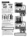
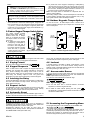
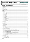
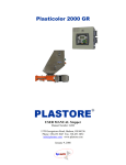
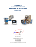
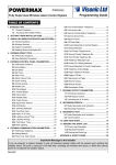
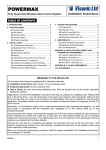
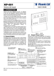
1
CL-83, CL-83M
Installation Instructions
Anti-Vandal, Access Control Keypad
1. INTRODUCTION
1.2 Indoor Keypad & Control Unit Features
1.1 Description
The CL-83 is a digital programmable access control keypad. CL83M is a similar keypad - mullion type. Each system includes an
outdoor, rugged, vandal resistant keypad and an indoor
sophisticated microprocessor-controlled keypad, as shown in
figure 1.
• Functions as the "brain" of the access control system.
• Includes 12 push-buttons, 3 LEDs and buzzer.
• Designed to accept data from both its own keys and from
the outdoor keypad.
• Suitable for flush and surface mounting (supplied with a
surface mounting box).
Power
supply
12/24V
DC/AC
• Includes a 10A relay, that activates the door strike or
performs any desired switching function.
• Programmable on site by use of its own keyboard.
• Non-volatile EEPROM stores programmed data, unaffected
by power failure.
• Programmable relay contact closure duration; toggle (latch/
Indoor Keypad
and Control Unit
(CL-8A EXT)
Outdoor Keypad
(CL-83)
Outdoor Keypad
(CL-83M)
Figure 1 - Using CL-83/CL-83M as an Access Control System
The system users have 56 individual, preprogrammed digital
codes (each code includes 1-8 digits), that they must key on the
outdoor / indoor keypads, to unlock electrically controlled doors or
barriers. More than 100 million code combinations are possible. A
penalty timer locks out the keypads for 30 seconds after entering
three consecutive erroneous codes. User codes may be
individually deleted.
The system has programmable AUXILIARY open-collector output
with seven powerful operating modes. Each user code can be
programmed to operate the internal RELAY, the AUXILIARY
output, or BOTH.
An AMBUSH digit, if entered after the last digit of the user code,
causes a one-second pulse of the PANIC output, used to send a
message to the security personnel if the user is forced to disarm
the system under violence or menace.
unlatch) mode may be selected if required.
• PANIC output is triggered by pressing the # and * keys
simultaneously, on the indoor or outdoor keypad.
• REQUEST TO EXIT remote input trips the relay with a
remote switch or a detector.
• Tamper switch option available.
1.3 Outdoor Keypad Features
• Rugged, water and vandal resistant keypad.
• Includes 12 push-buttons and 2 LEDs.
• All the the functions that can be performed by using the
•
•
•
•
indoor keypad push-buttons can be done also by the
outdoor keypad push-buttons.
Tamper protected.
Suitable for surface mounting.
Power is received from the indoor keypad.
Environmental Protection: IP68
2. SPECIFICATIONS
Indoor Keypad and Control Unit (CL-8A EXT)
Code composition: 1 to 8 digits, any combination
Keypad type: 12 keys, 3 X 4, tactile operation
Operating voltage: 9-16 or 22-26 V AC/DC, selected with
jumper
Current drain: 15 mA in the standby state, 55 mA with relay and
AUXILIARY output active.
Power failure immunity: EEPROM retains all programmed
information even during total power loss.
Other protections: Watch-dog protection from processor hang-up.
Relay contact rating: 10A /30V AC or DC
Relay control: Programmable for 1 – 98 seconds pull-in duration,
or for toggle (latching/unlatching) mode.
AUX and PANIC output current sinking: Up to 100 mA (each
protected by an 18 ohm series resistor).
LEDs: Green indicates keypad status
Red and yellow have 1K ohm series resistors and
terminals for external connections
Operating temperature range: -20°C to 65°C (-4°F to 149°F)
Size: (H x W x D): 118 x 72 x 33 mm (4-5/8 x 2-3/16 x 1-3/8 in.)
Weight: 122 g (4.3 oz)
Color: White
Compliance with Stadards: CE
DE6218
Outdoor Keypads (CL-83, CL-83M)
Housing Material: Aluminium 6061 T6
Number of Keys: 12 (CL-83: 3 x 4 matrix, CL-83M: 2 X 6 matrix)
Number of LEDs: 1 green, 1 red
Operating Voltage: Supplied from CL-8A EXT keypad
Operating and Storage Temperatures: -40°C to +125°C
(104°F-257°F)
Dimensions (H x W x D):
CL-83: 130 x 81 x 19mm (5-1/8 x 3-3/32 x 3/4in.)
CL-83M: 180 x 44 x 21mm (7-1/8 x 1-3/4 x 27/32 in.)
Weight: CL-83: 290g (10 oz)
CL-83M: 310g (10.9 oz)
Color: Metalic gray (anodized aluminium)
Compliance with Stadards: CE
Environmental Protection: Waterproof and dustproof (IP68)
1
3. INSTALLATION
3.1 Indoor Keypad Mounting
Outdoor Keypad CL-83
Do not install outdoors!
Surface Mounting
Flush Mounting Optional
Standard, single-gang
electrical switch box
Mounting
knockouts
12 11 10 9
7 6 5 4 3 2 1
Use supplied cable
(see par. 3.3)
Wiring
knockout
Indoor
Keypad
Mounting
knockouts
100 mA MAX.
Supplied
box
RED LED
–
+
Wiring knockout
(1 OF 2)
1K
1
Remove screws and remove the
keypad from from the back box.
2
Use back box as a template, mark &
drill holes in mounting surface. Fasten
the back box to the mounting surface.
Fasten the keypad to its back box
with 2 screws.
1
Remove screws and remove the
keypad back box (not used).
2
Fasten the keypad to a single-gang
electrical switch box, provided that
its internal dimensions are not less
than 5cm (2 in.) wide by 7cm (2.8 in.)
high, by using 2 screws.
+
–
JP1
1K
JP3
Figure 2. Indoor Keypad Surface and Flush Mounting
1
3.2 Outdoor Keypad Mounting
2
100 mA MAX.
YEL. LED
3
4
18
5
Note: The CL-83M is designed for installation on a door frame.
Drill 2 holes in the mounting surface, insert wall anchors as
necessary and fasten the outdoor keypad to the mounting surface
by using 2 screws.
6
7
8
+
–
18
BUZ.
OR
REL.
9 10 11 12
BUZ.
OR
REL.
DOOR MAGSTRIKE
NETIC
OR
RELAY LOCK
N.O.
+12 OR 24 VDC
–
+
12V OR 24 V
AC / DC POWER
SUPPLY
Figure 4A. Wiring with CL-83
Cable
hole
(**)
Cable
hole
(**)
Outdoor Keypad CL-83M
Screw
caps (*)
Screw
caps (*)
RUBBER
GASKET
(***)
RUBBER
GASKET
CL-83
6 - 28 V AC / DC
DOOR CONTROL
POWER SUPPLY
CL-83M
Figure 3 - Outdoor Keypad Mounting
* Screw caps should be installed only after the system
mounting and test is completed.
** Cable hole diameter: 10-12 mm.
*** The rubber gasket is designed for mounting the CL-83/CL83M on an uneven surface and/or to prevent the formation of
dampness and dust inside the keypad.
3.3 Wire Gauges and Routing
Use # 20 AWG or larger diameters for relay connections to the
door strike, to the control panel or any other system used. All
other connections are to be made with # 22 AWG or larger. Route
the wires through the wiring knockouts on the back box. Two
cables (1 meter long) are supplied with the CL-83 / CL-83M, P/N
PAW 80011, 6x6005/AWG#22.
6
5
4
3
2
1
7
9
10
11
12
BUZZER
Use supplied cable
(see par. 3.3)
Indoor
Keypad
100 mA MAX.
RED LED
–
+
1K
100 mA MAX.
YEL. LED
+
–
JP1
1K
JP3
18
18
3.4 Wiring
IMPORTANT! Before wiring be sure to set The indoor keypad jumper
JP3 in the position that corresponds with the power source you are
using:
9 - 16 Volts - mount the jumper across the two pins of JP3.
22-26 Volts - remove the jumper or mount it on a single pin of JP3.
Perform wiring as follows (see figure 4A/4B):
A. Connect the door strike leads between one of the door control
power supply terminals and terminal 11 (N.O.) of the indoor
keypad. In case of a magnetic door lock, connect the lock’s
leads between one of the door control power supply terminals
and terminal 12 (N.C.) of the indoor keypad.
B. Connect the remaining terminal of the door control power
supply to terminal 10 (COM) of the indoor keypad.
C. Connect the panic buzzer / relay (a 12 or 24 VDC unit,
depending on power supply) between terminal 8 (PANIC) of
the indoor keypad and power supply positive (+) terminal.
D. Connect the auxiliary buzzer or relay (a 12 or 24 VDC unit,
depending on the power supply) between terminal 9 (AUX) of
the indoor keypad and the positive (+) terminal of the power
supply.
2
1
2
3
4
5
6
–
7
8
+
BUZ.
OR
REL.
9 10 11 12
BUZ.
OR
REL.
DOOR MAGSTRIKE
NETIC
OR
RELAY LOCK
N.O.
+12 OR 24 VDC
–
+
12V OR 24 V
AC / DC POWER
SUPPLY
6 - 28 V AC / DC
DOOR CONTROL
POWER SUPPLY
Figure 4B. Wiring with CL-83M
Important: When a 12VAC power source is used, LEDs connected
to the PANIC or AUX open collector outputs will light normally when
the output pulls down. Buzzers will not function properly, and should
therefore be avoided. When a 24VAC power source is used, neither
LEDs nor buzzers should be connected to the PANIC and AUX.
DE6218
Notes:
1. If the system is powered from a DC power supply, the AUX and
PANIC relays can be connected to terminal 7 (+).
2. The PANIC and AUXILIARY outputs each include an 18 ohm
resistor in series with the output. The maximum current
switching capability of each output is 100 mA.
E. Connect the AC or DC power supply leads to terminals 6, 7.
Caution! If the power supply provides AC, disregard polarity.
If the power supply provides DC, connect the negative lead to
terminal 6 and the positive lead to terminal 7 of the indoor
keypad.
F. Connect the remote request-to-exit switch or PIR contacts
across terminals 5 and 6 of the indoor keypad. To light the red
LED, connect the 12 or 24-Volt power supply across terminal
1 (+) and 2 (–) of the indoor keypad. To light the yellow LED,
connect the 12 or 24-Volt power supply across terminals 3 (+)
and 4 (–) of the indoor keypad.
B. To protect the indoor keypad if tampering is attempted by
removing the unit from the wall or by removing the front of the
case. This is accomplished by opening the tamper knockout in
the back box, allowing the tamper actuator to extend out of
the back box and contact the wall (see Fig. 5).
Note: The tamper switch is delivered as a separate item. For
ordering, specify TAMP-1.
When using a tamper switch, connect the tamper N.C. terminals to
a control panel’s normally-closed, 24-hour protection zone, or any
other system used to monitor the tamper contacts.
3.6 Outdoor Keypads Tamper Option
To use the CL-83 / CL-83M Tamper switch, connect the 2
Tamper terminals (see figure 6) to Tamper N.C. terminals of an
alarm control panel.
3.5 Indoor Keypad Tamper Switch Option
The indoor kaypad includes
tamper switch option TAMP-1, a
terminal block and a tamper
switch on a separate PC board.
The tamper switch can be used
in two ways:
A. To protect the indoor keypad
if tampering is attempted by
removal of the front part of
the case. In this configuration,
the tamper actuator remains
within the case, in physical
contact with the inner surface
of the keypad’s back box.
CL-83
Tamper
terminals
Fig. 5 - Tamper Sw. Installation
CL-83M
CL-83
CL-83M
Tamper
terminals
Figure 6 - Outdoor Keypads Tamper Switches
4. OPERATION
The main function of the system is to recognize valid user codes
and respond according to pre-programmed instructions.
wrong code, an automatic reset results, requiring the user to wait
a few seconds and then to repeat entry of the code again.
4.1 Keying Format
4.6 Lockout
The user code is always followed by [#]:
4.2 Keypad Response
When a valid access code is keyed, the keypad responds by
activating the on-board relay (usually allocated to unlock the
door), and/or activating the auxiliary circuit. Each of the 56
different access codes may be programmed to operate the onboard relay, the auxiliary output or both. The green LED
illuminates for as long as the internal relay remains energized.
4.3 Latching the Relay
A penalty lockout is provided to defeat “code-crackers”. Three
wrong entries result in a 10 minute lockout, during which an
auxiliary output is activated, but the keypad can be reset after 30
seconds by entering a valid user code.
4.7 Access under Duress
If you are forced to access under threat, press the programmed
AMBUSH digit after the last digit of your code. This activates the
PANIC output without arousing suspicion.
Enter the user code followed by the ambush digit
For special applications, the relay may be toggled, so that keying
the code once causes the relay to latch, and keying the code
again unlatches the relay.
4.8 Operating Tips
4.4 Request to Exit
A. Do not wait more than 5 seconds between successive
keystrokes, or else the keypad will reset.
The REQUEST TO EXIT input activates the access control relay
to open the door from inside without keying a code, thereby
facilitating quick and simple exit from the protected area.
4.5 Automatic Reset
B. To initiate an alarm without opening the door, press
simultaneously. This activates the PANIC circuit which is usually
connected to a silent alarm.
When keying user codes, the intervals between digits must not
exceed 5 seconds. Should the user exceed this time, or enter a
5. PROGRAMMING
Programming should be carried out as soon as installation is
completed. This provides a set of “instructions” which determines
how the keypad will react to various code inputs.
Programming changes can be made as many times as
necessary, but for security reasons, this operation is restricted to
the “master code” holder (the master user).
DE6218
5.1 Accessing the Programming Menu
The programming menu is accessible only by the master user
As soon as code programming takes place, this default code is
automatically replaced by the first newly allocated code - No. 01.
Because user code No. 01 will become the new master code, it
should be assigned to the person in charge of security.
3
All code allocations should be recorded, and a User Code
Programming Chart - Appendix A, is supplied for this purpose.
Remember! To prevent unauthorized programming, it is
important to assign a new master code which should be used
for programming only.
To access the programming menu:
The green LED will start flashing slowly, indicating that the
program- ming menu is active. You can now select various
programming functions by pressing a number key from 1 to 5
(see Table 1).
Table 1. Programming Menu
No. Function
1 Programming
user codes &
their extent of
control
2 Setting the
relay timer
Latching the
relay
3 Selecting the
AUX output
mode
4 Deleting a
single user
code
Deleting all
user codes
5 Ambush digit
Delete
ambush digit
Valid Entries
02 to 56 ⇒ # ⇒
[code] ⇒ # ⇒
[code (again)] ⇒ #
⇒ 1 or 2 or 3 ⇒ #
01 to 98 ⇒ #
Description
Assigns access codes (1 to 8
digit combination) to a
person or a group of users see Par. 5.3.
Sets relay pull-in duration
between 1 and 98 seconds
99 ⇒ #
Converts the relay to the
toggle mode (latch/unlatch)
1 to 7 ⇒ #
The number entered
determines the operating
mode (see Table 2)
User number,
User code corresponding to
02 to 56 ⇒ # ⇒
the user number entered is
[master code] ⇒ # deleted.
ÍÍ⇒ # ⇒
All user codes are deleted
[master code] ⇒ # together, except for code 01
0 to 9 ⇒ #
The programmed digit will be
valid until deleted or replaced
Í⇒ #
The ambush digit is canceled
Note 1: If the system detects an error during programming, the green
LED goes out for 3 seconds after [#] is pressed and then reverts to
slow flashing. This indicates that the data has not been accepted and
the entire programming sequence should be repeated.
Note 2: If you make an error while programming, press [Í] for quick
return to the programming menu.
5.2 Deleting all User Codes
Note: Besides the default master code (code No. 1), a specific code is
programmed in the factory as code No. 2. It is therefore important to delete
all codes before placing the system into service!
The response will be as follows:
After entering [4] – the green LED starts to flash rapidly
After entering [ÍÍ] followed by [#] – the green LED lights for 2
seconds, and resumes rapid flashing.
After entering the [master code] followed by [#] – the LED
remains lit for 2 seconds and then reverts to slow flashing.
5.3 Programming New User Codes
and Their Extent of Control
Prepare a list of user codes you want to program and record
them in your Programming Chart (see Appendix A).
A.
The user number is the number assigned to this user on the user
list, not the code.
The green LED lights for 2 seconds and starts to flash rapidly
then repeat
to verify
B.
The user code is any combination of numbers, up to 8 digits.
The green LED lights for 2 seconds and resumes rapid flashing
C.
Select a trip code from the list below to determine which
outputs will be tripped by the new user code.
1 to trip the relay only
2 to trip the auxiliary output only
3 to trip both the relay and the auxiliary output
4
The green LED lights steadily for 2 seconds and then flashes
slowly, indicating that the data has been saved and that you are
back in the programming menu. To program additional user
.
codes, follow the sequence A through C above, or quit by
Caution! Code No. 01 will now become the master code,
and will provide the only access to future programming.
5.4 Deleting Selected User Codes
The response will be as follows:
After entering [ 4 ] – the green LED starts to flash rapidly
After entering [user number] followed by [ # ] – the green LED
lights steadily for 2 seconds, then resumes rapid flashing.
After entering the [master code] followed by [ # ] – the green
LED remains lit for 2 seconds and then begins flashing slowly.
5.5 Setting the Relay Timer
[ TT ] is the relay pull-in time
To set duration from 1 to 98 seconds, enter a number from 01 to 98.
To convert the relay to toggle mode (latch/unlatch), enter 99.
5.6 Selecting the AUX Output Mode
[M] is a number selected from the mode column in Table 2 below.
Note: User codes must be authorized to activate the auxiliary
output.
Table 2. Auxiliary Output Operating Modes
Mode Description
1
Output is pulsed for 1 second by every user code authorized to
operate the auxiliary output.
2
Output is toggled (latch/unlatch) by every user code authorized
to operate the auxiliary output.
3
Output operates concurrently with the relay timer, but stays
enabled 5 seconds longer than the relay (operation time: TT+5
seconds). If the toggle mode has been selected for the relay
(TT= 99), the auxiliary output will be turned on for 5 seconds
each time the relay is toggled. This mode does not work for
user codes that are not programmed to operate the relay.
4
Latches by user codes authorized to trip the auxiliary output,
unlatches by pressing Í.
5
Turned on for ten seconds by pressing any key.
6
Output oscillates at the rate of 1 Hz after 3 consecutive code
errors. This condition will persist for 10 minutes, and may be
reset only by entering a valid user code (resetting is possible
only after the first 30 seconds, during which the keypad will be
locked out as a result of the 3 code errors).
7
Output turned on by pressing 1 and 3 simultaneously. Remains
on while either key is kept pressed.
5.7 Deleting the Ambush Digit
If you do not intend to use an ambush digit, it is imperative that
you delete the ambush digit code – to ensure that no previously
programmed digit remains in memory.
5.8 Selecting an Ambush Digit
[ A ] is the desired ambush digit, chosen from 0 to 9.
IMPORTANT: If you have programmed an ambush digit, you
must restrict user codes to seven digits each (or less) and you
must avoid choosing user codes ending with that same digit as
the ambush one.
5.9 How to Quit Programming
while the green LED is flashing slowly
The green LED will extinguish.
DE6218
6. RESETTING THE DEFAULT MASTER CODE
If you forget or misplace the master code (code No. 01) and it
two seconds and after that will start flashing slowly, indicating
that the programming menu is active.
becomes necessary to reprogram the keypad, you will have to
reset the master code to the factory default (1234) as follows:
Important Note: The master code has temporarily
reverted to 1234. Remember, however, that all other data
programmed previously remains intact!
E. Program a new master code (user code No. 01) immediately,
and record it in a secret, safe place.
If you choose to quit programming at this stage, press # while the
green LED is flashing slowly.
A. Open the keypad’s case, revealing the printed circuit board.
B. Install the jumper across the two pins labeled JP2. (See Fig. 4).
C. Momentarily short circuit the pins labeled JP1 using a screwdriver or jumper wire.
D. Wait ten seconds, remove the jumper from JP2, and
immediately key 1234#. The green LED will light steadily for
Appendix A. User Codes List
USER
No.
USER
NAME
USER
CODE
(1–8
DIGITS)
ACTIVATES
RELAY, AUX
OR BOTH
OUTPUTS (*)
USER
NUMB
ER
01
02
03
04
05
06
07
08
09
10
11
12
13
14
15
16
17
18
19
20
USER
NAME
USER
CODE
(1–8
DIGITS)
ACTIVATES
RELAY, AUX
OR BOTH
OUTPUTS (*)
21
22
23
24
25
26
27
28
29
30
31
32
33
34
35
36
37
38
39
40
USER
No.
USER
NAME
USER
CODE
(1–8
DIGITS)
ACTIVATES
RELAY, AUX
OR BOTH
OUTPUTS (*)
41
42
43
44
45
46
47
48
49
50
51
52
53
54
55
56
* Each user can activate RELAY, AUX OR BOTH outputs, as described in paragraph 5.3C.
Appendix B. Programming Summary
Important! First access to the programming menu is gained through the factory default master code 1234. After programming, User
Code No. 01 becomes the master code.
No.
Function
Keying Format
Format Explanation and Correct Response
1
Access to
Programming Menu
[ÍÍ] [Master Code] [ÍÍ]
•
The green LED starts to flash slowly - the programming menu is active!
2
Deleting all previous
User Codes
[4] [ÍÍ]# [Master Code] #
•
3
Relay timing
[2] [TT] #
•
4
Selecting AUX output
operating mode
[3] [M] #
•
•
5
Defining an AMBUSH
digit
[5] [A] #
•
•
After pressing [4] - rapid flashing;
[ÍÍ] deletes all user codes except for code No. 01;
After keying [ÍÍ]# - steady light for 2 seconds and then rapid flashing
After keying [Master Code]# - steady light for 2 seconds and then slow
flashing.
After pressing [2] - rapid flashing;
[TT] = 01 to 98 seconds; 99 selects the toggle mode, in which a user
code will latch or unlatch the relay;
After keying [TT]# - steady light for 2 seconds and then slow flashing.
After pressing [3] - rapid flashing;
[M] = A code specifying the operating mode of the AUX output
(selected from Operating Modes Table below).
After keying [M]# - steady light for 2 seconds and then slow flashing.
After pressing [5] - rapid flashing;
[A] = Ambush digit, 0 to 9 (see note C below)
After keying [A]# - steady light for 2 seconds and then slow flashing.
DE6218
•
•
•
5
No.
Function
Keying Format
Format Explanation and Correct Response
6
Deleting the
AMBUSH digit
[5] [Í] #
•
7
Programming user
codes (prepare a
list - see Appendix A)
[1] [NN] # [C]# [C]# [F] #
•
•
•
•
•
Deleting individual
user codes
8
[4] [NN] # [Master Code] #
•
•
•
•
After pressing [5] - rapid flashing;
[Í] = Deletes the Ambush digit
After keying [Í]# - steady light for 2 seconds and then slow flashing.
After pressing [1] - rapid flashing;
[NN] = The serial number of the code user, 01 to 56
After keying [NN]# - steady light for 2 seconds and then rapid flashing.
[C] = The access code allocated to this user, 1 to 8 digits
After keying [C]# - steady light for 2 seconds and then rapid flashing.
Repeat [C]# for verification; the LED responds as before.
[F] = A code defining which outputs will be tripped by this user code
1: Authorization to trip the relay only
2: Authorization to trip the AUX output only
3: Authorization to trip both relay and AUX output
After keying [F]# - steady light for 2 seconds and then slow flashing.
After pressing [4] - rapid flashing;
[NN] = The serial number of the code user, 02 to 56
After keying [NN]# - steady light for 2 seconds and then rapid flashing
After keying [Master Code]# - steady light for 2 seconds and then slow
flashing.
Notes:
A.
B.
Quit programming by pressing [#] when the green LED flashes slowly.
If, while entering data, the green LED responds by going out for 3 seconds instead of lighting for 2 seconds, the data has not been
accepted. Press [Í] and repeat the entire sequence from the beginning.
An AMBUSH digit can not be used with 8-digit user codes, and should not be identical with the last digit in any code.
The PANIC output is tripped by pressing [Í] and [#] simultaneously.
C.
D.
Auxiliary Output Operating Modes
Mode
1
2
3
4
5
6
7
Description
Pulsed for 1 second by every user code authorized to operate the auxiliary output.
Toggled (latch/unlatch) by every user code authorized to operate the auxiliary output.
Output operates concurrently with the relay timer, but stays enabled 5 seconds longer than the relay (operation time: TT+5
seconds). If the toggle mode has been selected for the relay (TT= 99), the auxiliary output will be turned on for 5 seconds
each time the relay is toggled.
Note: this mode does not work for user codes that are not programmed to operate the relay.
Latches by user codes authorized to trip the auxiliary output, unlatches by pressing [∗].
Turned on for ten seconds by pressing any key.
Oscillates at the rate of 1 Hz after 3 consecutive code errors. This condition will persist for 10 minutes, and may be reset only
by entering a valid user code (resetting is possible only after the first 30 seconds, during which the keypad will be locked out a
result of the 3 code errors).
Turned on by pressing 1 and 3 simultaneously. Remains on while either key is kept pressed.
WARRANTY
Visonic Technologies Ltd. and/or its subsidiaries and its affiliates (“the Manufacturer”)
warrants its products hereinafter referred to as “the Product” or “Products” to be in
conformance with its own plans and specifications and to be free of defects in materials
and workmanship under normal use and service for a period of twelve months from the
date of shipment by the Manufacturer. The Manufacturer’s obligations shall be limited
within the warranty period, at its option, to repair or replace the product or any part
thereof. The Manufacturer shall not be responsible for dismantling and/or reinstallation
charges. To exercise the warranty the product must be returned to the Manufacturer
freight prepaid and insured.
This warranty does not apply in the following cases: improper installation, misuse,
failure to follow installation and operating instructions, alteration, abuse, accident or
tampering, and repair by anyone other than the Manufacturer.
This warranty is exclusive and expressly in lieu of all other warranties, obligations or
liabilities, whether written, oral, express or implied, including any warranty of
merchantability or fitness for a particular purpose, or otherwise. In no case shall the
Manufacturer be liable to anyone for any consequential or incidental damages for breach
of this warranty or any other warranties whatsoever, as aforesaid.
This warranty shall not be modified, varied or extended, and the Manufacturer does not
authorize any person to act on its behalf in the modification, variation or extension of this
warranty. This warranty shall apply to the Product only. All products, accessories or
attachments of others used in conjunction with the Product, including batteries, shall be
covered solely by their own warranty, if any. The Manufacturer shall not be liable for any
damage or loss whatsoever, whether directly, indirectly, incidentally, consequentially or
otherwise, caused by the malfunction of the Product due to products, accessories, or
attachments of others, including batteries, used in conjunction with the Products.
The Manufacturer does not represent that its Product may not be compromised and/or
circumvented, or that the Product will prevent any death, personal and/or bodily injury
and/or damage to property resulting from burglary, robbery, fire or otherwise, or that the
Product will in all cases provide adequate warning or protection. User understands that a
properly installed and maintained alarm may only reduce the risk of events such as
burglary, robbery, and fire without warning, but it is not insurance or a guarantee that
such will not occur or that there will be no death, personal damage and/or damage to
property as a result.
The Manufacturer shall have no liability for any death, personal and/or bodily
injury and/or damage to property or other loss whether direct, indirect, incidental,
consequential or otherwise, based on a claim that the Product failed to function.
However, if the Manufacturer is held liable, whether directly or indirectly, for any loss or
damage arising under this limited warranty or otherwise, regardless of cause or origin,
the Manufacturer’s maximum liability shall not in any case exceed the purchase price of
the Product, which shall be fixed as liquidated damages and not as a penalty, and shall
be the complete and exclusive remedy against the Manufacturer.
Warning: The user should follow the installation and operation instructions and among
other things test the Product and the whole system at least once a week. For various
reasons, including, but not limited to, changes in environmental conditions, electric or
electronic disruptions and tampering, the Product may not perform as expected. The
user is advised to take all necessary precautions for his/her safety and the protection of
his/her property.
6/91
Visonic Technologies Ltd. (Israel): 24 Habarzel St. Tel Aviv 69710 ISRAEL. Tel: +972-3-768-1400 Fax: +972-3-768-1415
Visonic Technologies America (U.S.A.): 10 Northwood Drive, Bloomfield CT. 06002-1911. Tel: (860) 243-0833, (800) 223-0020 Fax: (860) 242-8094
Visonic (UK): Unit 1, Stratton Park, Dunton Lane, Biggleswade, BEDS. SG18 8QS. Tel: (01767)600857 Fax: (01767)601098
Internet: www.visonictech.com
Tech. Support E-mail: [email protected]
Visonic Technologies Ltd. 2003, CL-83, CL-83M, DE6218- (Rev. 1, 04/03)
6
DE6218