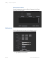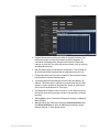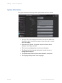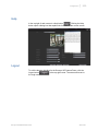
1
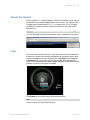
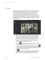
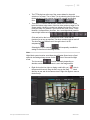
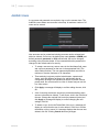
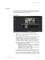
Configuration and Operation Guide XX214-40-04 Surveyor® HD/SD Series Network Camera Domes Vicon Industries Inc. Tel: 631-952-2288 Fax: 631-951-2288 Toll Free: 800-645-9116 24-Hour Technical Support: 800-34-VICON (800-348-4266) UK: 44/(0) 1489-566300 Vicon Industries Inc. does not warrant that the functions contained in this equipment will meet your requirements or that the operation will be entirely error free or perform precisely as described in the documentation. This system has not been designed to be used in life-critical situations and must not be used for this purpose. www.vicon-security.com Document Number: 8009-8214-40-04 Product specifications subject to change without notice. Issued: 514 Copyright © 2014 Vicon Industries Inc. All rights reserved. General Information Chapter 1 Introduction | 1-1 1 This chapter provides general information about the Surveyor® HD and Surveyor SD Network Dome Web Browser interface. Refer to the end of this chapter for the organization of the rest of this manual. The chapter consists of the following topics: Topic Page General Information 1-2 Organization of this Manual 1-4 Surveyor HD/SD Network Dome XX214-40 1-2 | Chapter 1 Introduction General Information The information in this manual covers the use of the Web Browser interface to configure and control the Surveyor HD and Surveyor SD (Surveyor HD/SD) Network Dome. Note Read all instructions before beginning any configuration. The easy to follow menu system provides screens to view live video, setup transmission settings for two streams of video, customize image, time/date, network, event and schedule settings, configure PTZ tours, sectors, masks and titling, and much more. The Web Browser interface will run on a Microsoft® Windows® Internet Explorer® platform. ActiveX® controls are required to view streaming video when using Internet Explorer. XX214-40 Surveyor HD/SD Network Dome Organization of this Manual | 1-3 Organization of this Manual Chapter Description 1 Introduction: Provides general information about the Surveyor HD/SD Network Dome Web Browser Interface 2 Configuration: Describes how to setup the Surveyor HD/SD Network Dome Appendix A VNSetup: Provides how to use this tool for ViconNet® installations Appendix B VLC: Provides how to use VLC program to view video Note Always check the Vicon website, www.vicon-security.com, for the latest updated manuals. VMS Compatibility The Surveyor HD/SD Camera Dome is an Onvif compliant open platform product designed to be used with multiple Video Management Systems (VMS). For initial setup when using the ViconNet VMS, refer to Appendix A for information on using the “VNSetup” discovery and configuration application. VMS specific tools may be necessary to use the dome with each system, such as a Discovery Tool. Refer to their documentation Surveyor HD/SD Network Dome XX214-40 Configuration Chapter 2 Configuration | 2-1 2 This chapter provides configuration information for the Surveyor HD/SD Network Dome. The chapter consists of the following topics: Topic Page Web Browser Interface 2 How to Use this Manual 2 Access the Camera 3 Login 3 Live View 4 Add/Edit Users 6 Settings 7 Maintenance 30 System Information 32 Help 33 Logout 33 Surveyor HD/SD Network Dome XX214-40 2-2 | Chapter 2 Configuration Web Browser Interface The Web Browser Interface provides a user friendly interface to configure and control various features and functions of the Surveyor HD/SD camera dome. The interface allows the configuration of camera dome parameters, viewing live video, using PTZ, setting administrative controls and collecting camera dome reports and status information. How to Use this Manual There are six (6) functional areas (pages) on the Web Browser Interface, Camera Login, Live Video, Add/Edit Users, Settings, Maintenance and System Information. Each browser page will have its own section of the manual. Each page shows illustrating sample selections. Those pages that provide settings involving video display will display the video from the selected camera, in a scaled window, that reflects the changes made and applied. Note Some of the screens shown in this manual may differ slightly in appearance than those that display on your screen, but functionality will be the same or similar. XX214-40 Surveyor HD/SD Network Dome Configuration | 2-3 Access the Camera Open a browser (i.e., Internet Explorer). Enter the IP address or host name of the camera in the Location/Address field of your browser. The camera dome is shipped with a default static IP of 1.1.1.2; change your PC’s IP to match the Subnet if needed. Camera's IP address can also be found with ONVIF discovery tool. You may be asked to load ActiveX software; click to download it at this time. The Surveyor HD login screen displays. Login The initial screen prompts the user to login with a user name and password if at least one user account has been programmed in the camera dome. Upon first use, the default user name is either lower case admin with a password of password OR a user name of upper case ADMIN with a password of 1234. From the dropdown list, select a display language for the Web Browser Interface; currently only English is available. Click Submit to enter the Surveyor HD browser interface. Note In most screens, the active field turns blue. Surveyor HD/SD Network Dome XX214-40 2-4 | Chapter 2 Configuration Live View After the login process, the Live Video page displays. After initial power on, a splash screen will display information on Vicon, the camera name and the revision of the software; this will disappear as soon as any PTZ action is made to the camera dome. Along the left side of the screen there is a Navigation panel with tabs for selection of the other function areas; the tab icon turns blue when it is selected. If there are sub-screens, that word turns orange when selected. Additionally, a vertical blue bar appears to the right of the function when selected. Help and Logout buttons are provided at the top right of the screen. XX214-40 • A Select Stream dropdown list is provided to select the video stream to be viewed. There are currently two video streams to be viewed, one with H.264 compression and the second with H.264 or MJPEG (Onvif mode only) compression. Refer to installation manual XX21400 on how to configure the dome for ONVIF mode (DIP switch). • There are several icons at the top of the display screen. Hover the cursor over the icon to display its function. • Press the icon (page) to allow the video to display full screen (1X); click Close 1X Mode to return to normal view. • To take a snapshot of the current video (future release), press the icon (camera). A dialog box displays. Enter a name for the file; select where to store (Save to) the capture (SD/MMC or NAND). Click OK to save or Cancel to abort the procedure. • The icon (bell) is for alarms. If there is an active alarm, the icon turns red; clicking the icon acknowledges the alarm, if programmed. Alarm functionality is configured from the Alarms/Relay screen. Surveyor HD/SD Network Dome Configuration | 2-5 • The PTZ Action bar at the top of the screen allows for the quick selection of a Preset, Tour or Auto Tour by selecting the function from the dropdown list, then entering the function number and clicking Goto. • There are PTZ controls that become visible when the cursor is just below the bottom edge center of the live video (at the top when in Full Screen mode). Hovering over the icon displays its function. The icon turns blue when it is selected. The functions are Zoom In/Out, Focus Near/Far, Iris Open/Close, AutoPan, Aux 1 and Night Mode (used for manual night mode control). Click and hold on the icon to perform the zoom, focus and iris functions for as long as required. The other controls toggle on and off. The Auto Pan icon will have an X through it when it is not autopanning . Selecting the Focus controls will temporarily override the setting for Autofocus in the Image screen. Note Night Mode control must be set to Manual and Shutter Speed set to a fixed speed in the Settings-Image screen for the icon to be used for Night mode. The Iris controls function differently depending on whether autoiris or manual control is set in the Image screen. • Surveyor HD/SD Network Dome Right click on the live video to display a red bull’s eye ( ); this is the pan and tilt control. Drag the bull’s eye on the image in desired direction to pan and tilt the camera dome. Right click again to remove the bull’s eye. XX214-40 2-6 | Chapter 2 Configuration Add/Edit Users A user name and password are required to log on to the camera dome. The Add/Edit screen allows user accounts to be setup. A maximum number of 10 users can be entered. New accounts can be created and existing accounts can be reviewed and edited or deleted. On first use, the default user name (admin or ADMIN) and default password (password or 1234) will be listed; this can be changed according to the procedure below. It is recommended that the password be changed for the default admin for security. XX214-40 • To create a new account, enter a name in the User Name field; enter and confirm a password for that user in the appropriate field. (The active field turns blue.) The user name and password must have a minimum of 4 and a maximum of 32 characters. • Three authority levels are provided, administrator, operator and viewer, each with different privileges. An administrator has all configuration privileges. An operator has access to pan/tilt controls, preset recall, tour controls and Live View. A Viewer can just use the Live View screen. • Click Apply; a message will display to confirm adding the user; click OK. • A list of currently stored user accounts is provided and allows each account to be edited or deleted. To edit a user, click in the Edit field of the user. Change the required field, enter the password (twice) and click Apply; a message will display to confirm changing the user settings; click OK. • To delete a user, click in the Delete field of the user; a message will display to confirm that the user is to be deleted. Click Yes to confirm the deletion or No to cancel it. A message displays that the user was deleted; click OK. Clicking Cancel aborts any changes. Surveyor HD/SD Network Dome Configuration | 2-7 Settings The Settings area allows for configuration of a variety of controls, including Transmission, Image, Analytics (for future release), Date/Time, Network and Port, Alarms/Relay, Schedule, PTZ and SD Card. Transmission The Transmission screen provides settings of two streams of video. • Select Stream 1 or Stream 2 from the tabs at the top of the setup table; the selected stream turns blue. • Compression type is the method used to reduce the size of the video file while maintaining a useful level of image: select H.264 or MJPEG (for Stream 2 only). (MJPEG is not available in ViconNet mode but is available in Onvif mode; to know which mode you are in, go to System Information, VMS Mode. (VMS mode is the default.) • Resolution, the number of pixels displayed, controls the sharpness of the image; select from the dropdown list. HD Model: For Stream 1 select a resolution of 720P (720p camera: 1280x720) or 1080P (1080p camera: 1920x1080); for Stream 2, select a resolution of 640x368. SD Model: For Stream 1 select a resolution of 720 x 480; for Stream 2, select a resolution of 720 x 480. • Frame Rate (fps - frames per second) selects how many frames can be compressed and transmitted per second: select from 30 - 1 fps. • Rate Control: select Constant Bit Rate/CBR or Variable Bit Rate/VBR. A constant bit rate maintains the bandwidth utilization while a variable Surveyor HD/SD Network Dome XX214-40 2-8 | Chapter 2 Configuration bit rate varies the amount of output data per time segment depending on other factors, such as complexity of the scene the camera is viewing. This is not available if MJPEG is selected as compression type. Note Setting a low constant bit rate may cause a low frame rate in order to meet the CBR setting. • Bit Rate is how much data is transmitted in a given amount of time: enter any number between 64-12,000 Kbps. Bit rate directly affects the quality of the video; as bit rate increases, quality increases. This is not available if MJPEG is selected as compression type. • Force I Frame inserts a reference frame at the selected interval; select Disabled, 5 or 1. This is not available if MJPEG is selected as compression type. • Quality (for MJPEG compression): High, Medium, Low. • Select Apply to save settings or Cancel to abort. Clicking Set Defaults returns all Transmission settings to their default values. Image There are two levels of image control, standard and advanced. The standard level is presented on the Image screen. Note that many of these functions are inter-related. XX214-40 Surveyor HD/SD Network Dome Configuration | 2-9 • White Balance compensates for different colors under differing light sources: select Auto (automatic) or Manual control (manual control is further set up in Advanced Red/Blue Gain Value). If the Shutter Speed is set to below 30, the camera will force White Balance to be manual, regardless of how it is set. • Image Freeze freezes the image during preset solves, especially useful when using digital recorders by eliminating the preset solve motion: select Enabled or Disabled. • AGC Max Limit selects the highest level of Automatic Gain Control; AGC maintains a constant video signal, useful for cameras in low light environments to adjust light levels in the scene: provides a slide scale (0-1280). Higher settings increase light sensitivity but boost noise as well. This setting affects when the camera enters and exits night mode. • Shutter Speed chooses the speed that the shutter opens and closes: select from a choice of 19 speeds, AUTO 4, AUTO 8, AUTO 15, AUTO 30 or 4 - 10000 (1/4-1/10,000 sec). The AUTO selection settings limit slowest shutter speed; for example, a setting of AUTO 4 prevents the shutter speed from dropping below 1/4 sec. Higher speeds reduce light sensitivity without affecting the optical depth of field, as opposed to an iris adjustment. If one of the fixed speeds (not AUTO) is selected, WDR is not available. The selection of Shutter Speed impacts on several other functions; this is noted in the description of those functions. • Iris Control selects autoiris function, where the lens senses the lighting conditions and adjusts automatically, or manual iris control: select Auto (automatic) or Manual. This setting also controls how the PTZ iris controls on the Live View function, if opens the iris manually or sets the autoiris levels. When autoiris is on, the Close Iris and Open Iris buttons select the optimum video level the operator wishes the camera to maintain. • Iris Average Level adjusts the iris based on the average brightness intensity of the entire picture: provides a slide scale (0-255) when autoiris is enabled. • Iris Peak Level allows the autoiris to regulate the iris opening based on the video level of the brightest (intensity) object in the picture: provides a slide scale (0-127) when autoiris is enabled. • Backlight Compensation corrects the exposure of the subjects that are in a bright light source: select On or Off. If On is selected, this can be fine tuned from the Advanced screen. Surveyor HD/SD Network Dome XX214-40 2-10 | Chapter 2 Configuration • Wide Dynamic Range improves video exposure quality in scenes with high contrast between bright and dark areas, for example, if a shady area and a bright light area are in the same scene: select On or Off. WDR is not available if a fixed Shutter Speed is selected. Note WDR and BLC cannot both be selected On; if both are turned on, unexpected picture results may occur. • Focus adjusts how clear the image is: select Auto (automatic) or Manual. The camera only allows Manual focus at shutter speeds between 1/4 and 1/8. Additionally, if Auto is enabled and the Shutter Speed is below 30, the camera will switch to manual focus while zooming and then autofocus when zooming stops. Autofocus can be temporarily disabled using the Focus controls on the Live View. This can prevent the camera from hunting when it is locked on a subject and there is temporary movement in front of that subject. If autofocus is on, this movement would cause a focus adjustment for the new object and the subject would then be out of focus. XX214-40 • Night Mode allows the camera to be put into night mode: select Auto (automatic) or Manual; when Auto is selected, the lens senses when the IR filter is required. If Auto is selected, continue to the Advanced screen to set additional Night Mode controls. The functions on the Advanced screen are not available if Manual is selected. For Manual to work, the Shutter Speed must also be set to a fixed speed. • Aperture Control adjusts the lens opening to control how much light comes through the lens: select Auto (automatic) or Manual. Select Manual to use aperture setting controls on the Advanced screen. Shutter Speed must also be set to a Manual (fixed) in order to manually adjust aperture controls. • Select Apply to save settings or Cancel to abort. Clicking Set Defaults returns all Image settings to their default values Surveyor HD/SD Network Dome Configuration | 2-11 Select the Advanced button on the Image screen to access the advanced controls. Be sure to save (Apply) changes in the Image screen before selecting Advanced. Note The Advanced Controls should only be accessed by technically knowledgeable users; changes in this area impact the operation of the camera image sensor and can drastically alter performance. The Advanced Controls include: • Red and Blue Gain Value adjust the color balance of the image: provides a sliding scale (128 – 1023); the number appears in a box to the right of the slider. This is only available if White Balance is set to Manual in the Image screen. • Backlight Compensation Tuning fine tunes backlight compensation if set to On: provides a sliding scale (0 – 255); the number appears in a box to the right of the slider. This is only available if Backlight Compensation is set to On in the Image screen. • Horizontal and Vertical Aperture Setting control the sharpness of the image; the horizontal and vertical edge clarity can be finely adjusted: provides a sliding scale (0 – 63); the number appears in a box to the right of the slider. Aperture Control in the Image screen must be set to Manual for this to be functional. • Auto Night Mode Control allows changing light level sensitivity of the night mode control: select Low, Medium or High. Night Mode must be set to Auto in the Image screen. • Night Mode Color Mode allows selecting the color when the unit is in night mode: choice of Monochrome or Color. Surveyor HD/SD Network Dome XX214-40 2-12 | Chapter 2 Configuration • Lens Speed allows the selection of the lens motor control speed setting: choice of Low, Medium or High. • Picture Mode allows fine tuning of the resolution: choose Balance or Reso-Up; be aware that selecting the Reso-Up mode gives better resolution than Balance, but it also increases the noise level. • IR Curve Setting adjusts the focus to match the IR source: select Visible Ray, IR950NM or IR850NM. • Special Lighting Mode allows the image color to be more accurate for the lighting source: provides a choice of Normal, Sodium Light Vapor or Mercury Light Vapor. If the light source is unknown, leave as Normal; the color can be adjusted manually. • Select Apply to save settings or Cancel to abort. Clicking Set Defaults returns all Advanced Image settings to default values. Clicking Back returns to the standard Image screen. Analytics Video Motion Detection (VMD) will be available in a future release. XX214-40 Surveyor HD/SD Network Dome | Configuration 2-13 Date/Time This area provides programming and review of the time and date component of the camera dome. • The time and date can be set manually or set to synchronize with the host PC or SNTP Server. Select the desired radio button. • To set manually, enter the date and time (hours, minutes and seconds) from the dropdown lists; click Apply. • To synchronize with computer time, select Synchronize with computer time and click Apply. Note Making changes to Set Manually or Synchronize with computer time will cause the camera to stop streaming for about 20 seconds while updating. • To synchronize with SNTP server, enter the SNTP Server for the camera dome and click Apply. The time zone for the unit is set by selecting the correct time zone from the dropdown list. • Automatic daylight saving time adjustment can be enabled by checking the box. • The unit can be set to synchronize with the ViconNet Nucleus. Select Synchronize with ViconNet Nucleus Time Sync and click Apply. The ViconNet Nucleus IP is entered in the Maintenance screen. • Select the date format from the dropdown list, year/month day (YYYY/MM/DD), month/ day/year (MM/DD/YYYY) or day/month/year (DD/MM/YYYY) and time format of 12 hour or 24 hour from the dropdown lists; the location of the date/time display is done in the titling screen if time and date display is enabled. Surveyor HD/SD Network Dome XX214-40 2-14 | Chapter 2 Configuration • Select Apply to save settings or Cancel to abort. Clicking Set Defaults returns all Date/Time settings to their default values. Network and Port Consult your IT department as needed to configure the Network and Port screen. The port type (Network, SMTP, FTP, RTSP, SNTP) becomes bold when configuring that port. Network XX214-40 • Check the appropriate boxes to enable IP6 (for future release), DHCP or SNMP (for future release). DHCP (Dynamic Host Configuration Protocol) is a protocol that lets network administrators centrally manage and automate the assignment of IP addresses on a network. Although a DHCP server is mostly used to set an IP address dynamically, it is also possible to use it to set a static, known IP address for a particular MAC address. • Enter the unique IP Address and netmask of the camera dome in the entry box (if DHCP is not selected). • Enter the Default Gateway in its box. • Enter the address for the primary DNS (Domain Name Server); DNS provides the translation of host names to IP addresses on your network. DDNS (Dynamic Domain Name Service)is for future use. The MAC address displays the unit’s MAC address; this is a readonly field. Surveyor HD/SD Network Dome | Configuration 2-15 SMTP Use SMTP (for future release) to enable the sending of notifications and image email messages from the camera to predefined addresses. • Check My Server Requires Authentication, if your mail server requires it. • Enter the A/c. Name (account/user) as well as a password for the external SMTP server in the appropriate fields. • Enter a sender URL or address in the Sender box. • Enter the IP address and Port of the SMTP Server and the Email address of the message receiver. FTP The FTP server (for future release) enables the upload of new firmware and user applications. • Enter the IP Address and Port of the FTP Server. • Enter a User Name and Password for logging on to the FTP server. • Enter a path for storing uploaded files to the FTP server. RTSP The RTSP protocol allows a connecting client to start an H.264 stream. • Check the Enable Multicast box to allow RTSP multicast transmissions. Note When using ViconNet, the address to be used for multicast can also be set through the Custom Tab in VNSetup. • Enter the Multicast IP. SNTP • Enter the SNTP Server address in the box. Note If DNS is setup, a name can be entered if the IP address is not known. • Surveyor HD/SD Network Dome Select Apply to save settings or Cancel to abort. Clicking Set Defaults returns all Network settings to their default values. XX214-40 2-16 | Chapter 2 Configuration Alarms/Relay The Alarms/Relay screen allows review and programming of alarms. XX214-40 • The Enable Alarms box on the top left of the screen must be checked to enable any alarms; to receive an email alert in the event of an alarm, enter an email address in the Alarm Email Address field (future release). • The Ethernet loss alarm/event source can be Enabled or Disabled. When enabled, there is the option to activate/deactivate the auxiliary relay, ON or OFF from the dropdown list. The AUX box must be checked to activate the dropdown list. • Each External (hardware) alarm input (1-4) can be individually enabled or disabled from the dropdown list. • Each alarm input can be set with an active alarm state of Active High or Active Low; this chooses how individual alarm inputs respond when contact closures are made (low) or broken (high) (in essence, normally open or normally closed). Additionally, on a pressurized unit with a pressure sensor, one alarm can be set to Pres to indicate a pressure alarm. • Alarm Acknowledgement Mode can be set to Manual, Momentary or Auto (Timed, 1-90 sec); this determines whether an alarm is acknowledged manually by the operator, momentary so the alarm remains active until the alarm state is eliminated, or automatically after a predetermined period of time. • Local Report can be Enabled or Disabled, allowing the user to determine if the alarm indicator will display on the browser interface in Live View. Surveyor HD/SD Network Dome | Configuration 2-17 • The auxiliary relay can be selected to activate/deactivate upon an alarm by checking the AUX box and selecting ON or OFF from the dropdown list. Separate settings are provided for the alarm trigger (Set) and alarm condition removed or acknowledged (Reset). • For an action upon alarm, check the action box to allow the selection of go to a Preset, begin a Tour, begin an Autotour or None (no action) from the dropdown list. Once an action is selected, the preset, tour or autotour number can be selected from the dropdown list. To be able to send an email alert upon alarm, check that box. • The Relay Driver is programmable for Power On State, On or Off, and Output Type (the relay action), Momentary or Latching. • Select Apply to save settings or Cancel to abort. Clicking Set Defaults returns all Alarms/Relay settings to their default values. Refer to the Typical Relay and Alarm Connections section of the Wiring chapter in the Installation and Operation manual, XX214-00. Schedule A schedule of events for time of day and day of week can be set up. On the opening screen, any schedules will be indicated by a colored line at the time on the weekly chart; hovering over the line with the cursor displays the schedule number. A maximum number of 32 events can be scheduled. • The Enable Schedules box must be checked to allow schedules to run. • To edit or remove a schedule, select the designated number for the scheduled event from the dropdown list; then click either the EDIT Surveyor HD/SD Network Dome XX214-40 2-18 | Chapter 2 Configuration SCHEDULE or REMOVE SCHEDULE button. As an alternative, the edit screen can be accessed by double-clicking on the colored vertical line that marks it in the weekly chart. XX214-40 • Select the ADD NEW SCHEDULE button to create a schedule. • Selecting the ADD NEW SCHEDULE or EDIT SCHEDULE button displays the following screen. • The next available number will display in the Schedule No. field for a new schedule; if a schedule is being edited, that number will display. Check to Enable(d) or Disable(d) this schedule. • Select an action for the schedule, none, preset, tour, or autotour. Alarms 1-4 can be enabled, disabled or no change for the time scheduled; one auxiliary (relay) can be turned on, off or no change. • Set a schedule time in hours and minutes (24-hour format) and select if this should occur once, weekly or daily; if weekly is selected, choose the day of the week it should occur. • Click Save Schedule to save the new or edited schedule; Cancel aborts the changes or creation of new schedule. Set Defaults returns all settings to their default values. • Expiration options for scheduled events are provided, either expires after 1 - 52 weeks (from the dropdown) or never expires. Click the desired radio button. • REMOVE ALL SCHEDULES clears all scheduled events. • Select Apply to save settings or Cancel to abort. Clicking Set Defaults returns all Schedule settings to their default values. Surveyor HD/SD Network Dome Configuration | 2-19 PTZ Tabs are provided to access the PTZ related functions of Presets, Tours, Auto Tours, Masks, Sectors, Titling and Motor Control (settings). When making these settings, a small video window will display the video to guide selections. There are PTZ controls that become visible when the cursor is at the bottom edge center of the live video. Hovering over the icon displays its function. The icon turns blue when it is selected. The functions are Zoom In/Out, Focus Near/Far, Iris Open/Close, Auto Pan, Aux 1 and Night Mode . Presets Select the Presets tab. The following screen displays, where up to 79 presets can be set up and recalled. Note Certain presets numbered beyond 79 are reserved for special functions, including: presets 80-87, tour sequences; presets 88-89, autotour sequences; preset 90, pan/tilt lockout. • From the preset table list, select the preset number, 01 – 79. That number will appear in the Preset No. field. If that preset has been defined, the title displays in the table. If no title has been programmed, the default title displays (Preset XX, where XX is the preset number). • Right click in the video to display the bull’s eye. Position the camera dome to the PTZ settings required for the preset. Select SET to save the selected preset number to the current position and title. Surveyor HD/SD Network Dome XX214-40 2-20 | Chapter 2 Configuration • To set a title, click in the Title field and enter a logical title for the preset position. Multiple titles can be entered before clicking Apply. The title will display on the live video window if titling is enabled from the titling screen when the camera is in the preset position. • If a preset has been previously set, changing the information and clicking SET will overwrite the previous setting. • To recall a preset, select the preset number from the table and click the GOTO button; the camera dome will move to that position. • A CLEAR button erases the selected preset; selecting CLEAR ALL erases all 79 presets. • Select Apply to save settings or Cancel to abort. Clicking Set Defaults returns all Preset settings to their default values. Tours Select the Tours tab. The following screen displays, where up to 8 individual tours can be reviewed and programmed. Each tour consists of up to 32 steps; each step can be one of 10 action types: Preset, Dwell, Aux, (Call Another) Tour, (Call) Auto Tour, Repeat (Tour), Save State, Recall State, Alarm Acknowledge or No Action. XX214-40 • From the dropdown list, select the tour number, 1 – 8. The tour table lists the step numbers. • To program a tour, click in the Action field and select the action type from the dropdown list for each required step (each action can have up to 2 parameters; click in the parameter field to select from the dropdown list). When the tour programming is complete, select SET to save the selected tour number with the current information. The actions are listed below with their parameter options: Surveyor HD/SD Network Dome Configuration | 2-21 Preset calls a previously defined preset; enter parameter 1 as the preset number and parameter 2 as the preset solve speed (1-10, 10 being the fastest). Dwell inserts a “wait” cycle between actions; requires setting parameter 1 for 1-60 seconds wait time. AUX allows turning the relay on or off; set parameter 1 to On or Off. Tour calls another tour sequence; once the called tour is completed, control is returned to the calling tour. Requires setting parameter 1 as the tour number, 1-8. Autotour calls an autotour sequence; once the called autotour is completed, control is returned to the calling tour. Requires setting parameter 1 as the autotour number, 1 or 2. Repeat goes back to the beginning of the tour and starts over again, creating a programming “loop.” Requires no parameters to be set. Save State, typically used at the beginning of a tour, saves the current camera position and function, including autopan; typically used with Recall State. Requires no parameters to be set. Recall State, typically used at the end of a tour, returns the camera to where it was when the Save State command was issued. Requires no parameters to be set. Alarm Acknowledge acknowledges and resets the current (first-in, first-out) alarm action. No Action skips this step. Requires no parameters to be set. • To run a tour, select the tour number from the dropdown list or table and select the GOTO button. If the tour exists, the live video will display the running tour; if no tour has been programmed, an error message displays. • Use the CLEAR button to erase the currently selected tour; all information returns to defaults. CLEAR ALL clears all tours and returns to default settings. A confirmation notice will display before anything is cleared. Set Defaults will set all the tours back to their default (unprogrammed) state. Surveyor HD/SD Network Dome XX214-40 2-22 | Chapter 2 Configuration AutoTours Select the Auto Tours tab. The following screen displays, where up to two auto tours can be reviewed and programmed. Each auto tour is capable of 256 programmable pan/tilt/zoom functions per auto tour. The 256 functions are individual PTZ movements (steps). XX214-40 • From the dropdown list, select the auto tour number, 1 – 2. • To program an auto tour, click the RECORD/APPEND tab. This starts the record process. The status indicator on the right will state RECORDING. Right click inside the video display to activate the bull’s eye. Move the camera dome to the series of positions to be included in the auto tour. When the auto tour is complete, or the maximum number of steps is reached, click the STOP button; the status indicator on the right will state STOP. A Steps Remaining field keeps track of the number of steps used. • Use the RECORD/APPEND to add commands to the end of the existing auto tour. • From the Run Mode dropdown list select the action of the selected auto tour: Repeat causes the auto tour to begin again and run indefinitely; Halt ends the autotour. • To run an auto tour, select the auto tour number and click the PLAY button; the live video display will begin the auto tour. • The CLEAR button erases the selected auto tour. A confirmation notice will display before anything is cleared. • A Status field displays what function is currently active. • Clicking Set Defaults returns all Auto Tour settings to their default values. Surveyor HD/SD Network Dome Configuration | 2-23 Privacy Masks Select the Masks tab. From here, up to 80 rectangular privacy masks can be programmed and reviewed. Up to 10 masks can be configured on each view; move to another view to add more masks. An error message will display if you try to create more than 10 masks. • From the dropdown list, select the Active Mask No. to be configured or selected. • To configure a mask, move the camera to the view where the mask is required by right clicking inside the video display to activate the bull’s eye. From the dropdown list, select if Masking is Enabled or Disabled. The masking feature provides a Dynamic Masking Zoom Level feature, which is adjustable from 0 – 360 (where 0 is Off and 360 is the maximum optical zoom of the camera). With this feature, the privacy mask will only display if the camera zoom level is greater than or equal to the zoom level set for the privacy mask. In this way, the mask does not appear on screen to obscure the view when the camera zoom level is lower than the privacy mask zoom level. Select 0 – 360 from the dropdown menu. After a change is made, a message will pop-up to restart the camera. Note Titles and Privacy Masks cannot be enabled at the same time. Surveyor HD/SD Network Dome • In the Rectangular Mask field, click Add to configure the mask. Pan and tilt operation is locked out when a privacy mask is being edited. A field displays how many masks of each type are remaining. (The Sloping Mask will be available for future use.) • After clicking Add to add a mask, an editable green rectangle or shape will display in the center of the video. The shape has XX214-40 2-24 | Chapter 2 Configuration moveable corners that can be used to customize the size and location the rectangle using the mouse. • Once the shape has been sized and positioned, click Save Mask to save the setting. Clicking outside the mask area changes the outline to red, indicating that the mask is not editable. Click in the mask to edit it; the outline will change to green. Note There can only be one editable (green) mask at a time. XX214-40 • To select an existing mask by number, enter the mask number from the dropdown list and click the GOTO MASK tab; the dome will move to the location so the mask is visible in the video display. • If the mask exists, the mask can be moved or resized by clicking inside the mask with the mouse and then moving the mask; the mask can be sized by clicking on any corner or side and dragging. • Use the DELETE MASK tab to erase the selected mask; DELETE ALL causes all possible masks to be removed. A confirmation notice will display before anything is cleared. • Select Apply to save settings or Cancel to undo changes. Set Defaults removes and disables all masks. Surveyor HD/SD Network Dome Configuration | 2-25 Sectors Select the Sectors tab. The following screen displays, where it is possible to divide the 360° field-of-view of the dome into up to 16 sectors (segments) and review and define the sector boundaries. • From the dropdown list or the sector number column in the table, select the sector number, 01 – 16. The table lists the sector number, the title for that sector and the mask condition; with the mask enabled, the video from the sector will be blacked out. • To create a new sector or edit an existing sector, click the Start Sector Programming button. Position the camera dome to the location of the start of the sector; click the Set Sector button; click the End Sector Programming button. The right boundary of one sector is the left boundary of the next sector. Note: The end of a sector is set by programming the start of the next sector (i.e., the start of sector 2 is the end point for sector 1). The Start position of the sector is the center of the video display • Give the sector a logical title. Clicking a title in the table allows that title to be edited, deleted or a new title assigned. If no title has been assigned, the default title displays, SECTOR X, where X is the sector number. • By selecting Enabled from the dropdown in the Mask column, the sector can be blacked out on Live View. • A Status notification will display the current state of the sector. To the right of the Status, a circle presents a graphic indication of the sectors that have been programmed. Surveyor HD/SD Network Dome XX214-40 2-26 | Chapter 2 Configuration • Use the GOTO SECTOR button to command the camera dome to move to the selected sector. • Click Apply to save settings or Cancel to undo any changes. Use the Set Defaults button to program default titles and mask status for all 16 sectors. Click Reset to clear position data from the selected sector; Reset All clears all position data and resets titling and mask to default values. Titling Select the Titling tab to program the titling parameters. When the screen displays, all currently defined titles display overlaid on the video in highcontrast to the live video display. Note The Camera Name is different than the Camera Title. The Camera Name is what is used when selecting the camera in a video management system; the camera title is what displays on the video display, when enabled. XX214-40 Surveyor HD/SD Network Dome Configuration • | 2-27 To the right of the video display, enter a camera title. This is the name that will display on the live video. Text size is 2X. Select a text language of English, Spanish, French, German or Italian (currently only English is available; other language settings for future release). Note Titles and Privacy Masks cannot be enabled at the same time. • Individual title enabling can be turned on or off from a dropdown list (some titles also provide a Fade option). The following titles can be enabled or disabled: Camera, Time and Date, Preset, Sector, Lens, Alarm, AUX, Compass, Azimuth, Temperature and Humidity; for pressurized domes only, a Pressure title is available. Additionally, an Enable Titles is available that enables or disables all titles. Note Enabling refers to whether the titles are displayed on the Live Video. If Enable Titles is turned ON, the individual titles can be turned ON or OFF; if Enable Titles is turned OFF, no titles will display on Live Video. The Camera Name is different than the Camera Title. The Camera Name is what is used when selecting the camera in a video management system (such as ViconNet); the Camera Title displays on the video display, when enabled. • Time to fade control is available; from the dropdown list, select the amount of time the title should display before fading from view on the video, 1-60 seconds; the Fade option is available for Preset, Sector, Lens, Aux, Compass, Azimuth, Temperature, Humidity and Pressure titles. • The title position can be changed in real time by clicking and dragging it to the desired position. • Select Apply to save settings or Cancel to undo all changes. Clicking Set Defaults sets default positions to all titles. Camera Name and Camera, Preset and Sector titles will not change. Surveyor HD/SD Network Dome XX214-40 2-28 | Chapter 2 Configuration Motor Control From the Motor Control tab, the following screen provides a variety of pan, tilt, zoom and autopan parameters for setup. • PT (Pan/Tilt) Lockout can be selected On or Off via radio buttons; this enables or disables pan and tilt movement. This feature prevents the camera dome’s position from being tampered with. This allows the dome to respond only to preset positions, eliminating the operator’s ability to manually position the dome. It also allows a unit to be locked onto a subject for recording or monitoring specific activity. The camera dome retains its capability of zoom, focus and iris control while locked. • To Set Pan Limit Left, move the camera dome to the position for the limit for panning left; click the Set button to save this position as the limit (this is the center of the video display); click Clear to cancel the setting. Repeat the procedure to set the right pan limit, autopan left limit and autopan right limit. After the pan limit stops are set, the physical range between these limits is the valid range. The camera dome will not move outside these limits. Setting pan limits also sets AP limits if the AP limits are outside the of the pan limits. The only exceptions are prerecorded tours and previously stored presets. When a continuous rotation dome is in autopan, it will rotate in a full circle until autopan is disabled. When an application, such as a wall-mounted camera on a building, does not require continuous rotation, limits can be set to define the left and right boundaries. When the autopan limits are set and the camera is placed into autopan it will pan until it reaches a limit. It will then XX214-40 Surveyor HD/SD Network Dome Configuration | 2-29 reverse direction until it reaches the opposite limit, repeating this cycle indefinitely. • Use the Camera Orientation field to set the north direction. Move the camera dome to face north (use a compass as necessary); click Set True North to set this position as the north direction. This affects the compass display, a 0-360º pan reading display and a -2º to 92º tilt reading display (Azimuth) and Compass direction. This feature allows an operator to program and utilize a continuous absolute pan and tilt display reading. • PTZ Timeout can be set for 1-255 seconds from a sliding scale (the number appears in a box to the right of the slider); this allows the unit to timeout if manual pan, tilt or zoom remains active after a loss of communication for a programmable amount of time. PTZ Timeout Action selects what will happen upon timeout, Stop or select a Preset 1-79. A setting of 0 disables the PTZ Timeout function. • From the dropdown list, Enable or Disable Zoom Scalable Pan/Tilt; when enabled, this adjusts the pan and tilt speed relative to the amount of magnification to compensate for the size of the image. When the camera is zoomed in on a subject, the speed is slowed down to compensate for the size of the image. • Max Manual Pan/Tilt/Autopan Speed provides a sliding scale to set the maximum speed of movement in degrees per second (1-400/150/42 dps, respectively); the number appears in a box to the right of the slider. This feature allows the user to set the optimum speed for each individual camera. • Auto Home can be Enabled or Disabled; when enabled, from Auto Home Action, the camera dome can be set to automatically go to a programmed preset number location or run a tour or autotour after the programmed time duration of no activity on the dome has occurred. This Auto Home Timeout can be selected from the dropdown list, 1-60 minutes. Auto Home Power Up, when enabled, sets the dome to go to its home position upon power-up. • Select Apply to save settings or Cancel to undo changes. Click Set Defaults to return all Motor Control settings back to default values. Surveyor HD/SD Network Dome XX214-40 2-30 | Chapter 2 Configuration SD Card (for future release) Data from the dome can be saved to an SD card. Parameters for the SD card are set from the SD Card screen. Maintenance Select the Maintenance tab to access a list of configuration controls. • XX214-40 Log capability is for future release. Surveyor HD/SD Network Dome Configuration | 2-31 • Camera Maintenance provides the ability to upgrade firmware. Use the Browse button to locate the firmware and press Upgrade. A countdown will display and a dialog box will request to restart the camera; click OK and Yes. After the camera restarts, it will go through an initialization process. • Use the Backup button to backup the configuration. This will back up all the browser-defined settings that are programmed into the unit. • Configuration data can be restored; search for files using the Browse button and then click the Restore button. • ViconNet features allow entering a Nucleus name and Nucleus IP address. This information is required to communicate with the VMS system; it is also required for the Date/Time screen to synchronize time to the ViconNet Nucleus IP Time Sync. • The Diagnostics Features can be turned On or Off. When turned on, the camera dome will go through a series of movements to measure accuracy. • Select Apply to save ViconNet and Diagnostic settings or Cancel to abort changes • Manually reboot the camera by clicking the Restart Camera button; click Restore Defaults to return all Maintenance settings, except Network settings, to their default values. Surveyor HD/SD Network Dome XX214-40 2-32 | Chapter 2 Configuration System Information The System Information screen provides specific details about the camera. XX214-40 • The top of the screen displays the camera name and the VMS Mode, ViconNet or Onvif; it may be necessary to know this mode for certain dome functionality. • Under About IP Camera, find release versions for Kernel, Uboot, Software, Video Player and GUI. • The License area displays the current license information. • The Support Info lists important information to assist the user in finding technical support. • The Credits area provides credit to other companies, as required. • The Copyright area provides Vicon’s copyright. Surveyor HD/SD Network Dome Configuration | 2-33 Help In the top right of each screen is a Help button .Clicking the Help button opens a dialog box that explains the functions on the current screen. Logout To exit the browser interface for the Surveyor HD Camera Dome, click the Logout button .in the top right corner. The screen will revert to the Login screen. Surveyor HD/SD Network Dome XX214-40 2-34 | Chapter 2 Configuration Help In the top right of each screen is a Help button .Clicking the Help button opens a dialog box that explains the functions on the current screen. Logout To exit the browser interface for the Surveyor HD Camera Dome, click the Logout button .in the top right corner. The screen will revert to the Login screen. XX214-40 Surveyor HD Network Dome VNSetup and ViconNet Appendix A VNSetup and ViconNet | A-1 A This appendix provides information about configuring the Surveyor HD Network Dome when using it with the ViconNet VMS. This includes configuring VNSetup and various guidelines when using the dome with ViconNet. The chapter consists of the following topics: Topic Configuring ViconNet Using the Surveyor HD with ViconNet Surveyor HD Network Dome Page A-2 A-12 XX214-40 A-2 | Appendix A VNSetup and ViconNet Configuring ViconNet The ViconNet CD contains the ViconNet software needed to setup your system, including the application setup, the camera firmware and setup software (VNSetup). Be sure the ViconNet Workstation meets the minimum requirements, is running the ViconNet application (minimum version 6.5) (VNSetup, minimum version 3.68). The VNSetup application is found on the ViconNet CD under software, IP Camera Setup. Refer to appropriate ViconNet documentation. If you are using ViconNet version 7, you must have Surveyor firmware 6.9.13 minimum. Network Considerations The Surveyor HD Network Dome can be connected to any ViconNet network (Version 6.5 software and higher). Kollector Recorders and ViconNet Workstations can be used for live viewing and recording of network-streamed video. A network can be as simple as a single Surveyor HD connected to a ViconNet Workstation or can be complex with the addition of several networks interconnected via WAN. When adding a Surveyor HD to the ViconNet network, the following items must be considered: The number of cameras on a switch with respect to switch capabilities and system bandwidth mapping. Bandwidth limitations on ports connected to workstations (using 100 or 1000 Mbps). Workstation capabilities such as processing speed, disk write speed and display card strength. Storage size and location types including local Workstation recording, attached SCSI RAID and integrated NAS/SAN devices. The default parameters on the dome are (static IPs): Factory Defaults Network Defaults IP address: [1.1.1.2] IP address: [1.1.1.2] Nucleus IP address: [1.1.1.1] Nucleus IP address: [1.1.1.1] Net Mask address: [255.255.255.0] Net Mask address: [255.255.255.0] Gateway address: [1.1.1.100] Gateway address: [1.1.1.1] On first startup, the dome will attempt to establish connection to the Nucleus with the default address (1.1.1.1). Connecting it to an active Nucleus is done through the VNSetup utility. Note Selecting Factory Defaults will NOT change the Nucleus IP address once it is set. XX214-40 Surveyor HD Network Dome VNSetup and ViconNet | A-3 Groups and Users Restrictions ViconNet allows creating Multiple Groups and Users in order to limit the rights to different levels. For more information on how to create Users and Groups, refer to the latest revision of ViconNet manual XX113. Configuring the Network Settings Note Before starting, make sure that VNSetup is installed on the configuring PC\workstation. Installation is done using the CD included. There are two ways to change the dome network settings: Activating the camera for the first time: via VNSetup application. Connecting the camera to an active Nucleus: via ViconNet application (using the same Nucleus the camera is configured for is necessary). Note In order to install firmware, the PC and camera must be on the same IP network subnet. Surveyor HD Network Dome XX214-40 A-4 | Appendix A VNSetup and ViconNet Using the VNSetup Utility VNSetup consists of several TABs. Each TAB provides different functionalities. Note Once the ViconNet Camera Setup is installed, a shortcut is placed on the desktop for future use. 1. 2. Make sure the MAC address and password of the camera is available. Use MAC Address log provided. Verify that the camera is physically connected to the configuring workstation via the network. Setup TAB Note Since the Setup configuration affects the entire installation process, it MUST be configured prior to attempting upgrades or logging. In the File Setup TAB, 3 fields are defined. The Upgrade files field indicates the installation upgrade directory. The Log files field allows the user the ability to put a copy of log files in a predefined directory. Password management selects a directory to save all password files. (By default, the setup files will be installed to C:\VUG.) In Password file status, the number of passwords stored is displayed. Load a list of passwords is intended for very large sites only. Contact Technical Support to use this feature. Setup XX214-40 Surveyor HD Network Dome VNSetup and ViconNet | A-5 Select TAB The Select TAB allows the user to select the relevant IP Unit in order to change its settings or to upgrade its version. 1. From the Unit selection list, select the relevant IP product. In case of multiple sites, it is advised to use the filter under the Unit Type field. Click on any column tab to sort names by that definition in ascending or descending order. 2. Once the desired unit has been selected (highlighted), notice the icon, indicating a password protected unit. In order to change the selected unit’s settings on the local PC that is running the VNSetup, the unit's unique password (provided on MAC sticker) must be entered. The screen will display how many units there are and how many of those are password protected (locked). A remote unit, as in systems using network routers and VLANS (virtual LANs), will not display in the Unit selection list, as those block network broadcast traffic. If you want to select a remote unit, manually enter the IP address in the IP address of remote unit field and click Find remote unit. The remote unit is added to the list (if needed, use a PC on the same VLAN or network to discover the device). 3. Password authentication There are two authentication options. You can either authenticate a specific unit, by entering its password, or use a Nucleus authentication, allowing you access to all units in the network that are connected to that Nucleus. 3.1. Unit authentication - On the Unit password field, enter the unit password and press the Add password button. Once approved, notice that the icon has disappeared and the user may proceed to next phase. The password will be saved on this PC. Note The unit password is supplied on the sticker with the MAC address in the accessory kit package. 3.2. Nucleus authentication - On the Nucleus admin login field, enter a valid Nucleus IP address and admin password and press the Login button. Once approved, notice that the icon has disappeared from all the units currently connected to the selected Nucleus and the user may proceed to next phase. 4. Press the Select Unit button on the lower section of the screen. Surveyor HD Network Dome XX214-40 A-6 | Appendix A VNSetup and ViconNet Note You MUST click the Select button to select the unit to the list for further editing; verify that it is added to the list. 5.The selected unit appears on the Selected Unit section on the top of the screen and settings can be changed. 1 Select Unit 2 3.2 3 4 Unit TAB The Unit TAB allows the user to change the following settings: Unit name, Nucleus IP address, IP address, Subnet mask, Gateway, DNS, DHCP, Time zone, Set unit clock from PC clock (synchronize time with PC), Daylight saving time, Local time, Local date, and Debug level (if requested by technical support), on a scale of 0-4, where 4 is the highest debug level. Note The Apply button must be pressed for changes to take effect. Note Verify all IP addressing parameters with your IT administrator. Note In order for the DHCP option to work properly, verify that the DHCP server does not expire the IP address licensed to the encoder. (Encoder should always receive the same IP address from the DHCP server.) XX214-40 Surveyor HD Network Dome VNSetup and ViconNet | A-7 Unit Install TAB The Install TAB allows the user to install/upgrade newer versions. Choose the correct version and click Install to send to the selected unit. Install Surveyor HD Network Dome XX214-40 A-8 | Appendix A VNSetup and ViconNet Info TAB The Info TAB displays the selected IP product general information. Info Advanced TAB The Advanced TAB functionalities allow the user to handle unexpected events on a specific remote unit when they occur. When a problem occurs, the user can choose to Unjam Unit to restart the unit’s firmware, Restart Unit to restart the hardware, Net Defaults to return the initial network settings and Factory Defaults to return to the initial configuration. Get core and Get logs are used mostly for debugging purposes and are not relevant for the Surveyor HD. The Main application starting mode, Application start status may be “Unknown”, “Application loaded successfully” or “Loading of application is disabled.” The Disable Load button allows the pausing of the application load in case of software issues while still permitting communication via VNSetup; the Enable Load button resumes the application load. The default value for proper dome operation MUST be “Application loaded successfully” and the Enable button grayed out. XX214-40 Surveyor HD Network Dome VNSetup and ViconNet | A-9 Advanced Note: If Factory defaults is selected, make sure that Application start status states Application loaded successfully. The screen would look as below. If that is not the case, Enable load will not be grayed out; press the Enable load button. Click OK when the box displays. Surveyor HD Network Dome XX214-40 A-10 | Appendix A VNSetup and ViconNet Custom TAB The Custom TAB allows setup of the video streams. Custom Function Selection Function Option Function Selections Operation Mode – Select the Surveyor HD interface mode. Choose Function Options from Vicon or ONVIF mode, which ignores the DIP switch settings on the unit, or DIP, which allows the Surveyor HD to operate according to the DIP switch settings. Refer to the Installation & Operation manual for setting the DIP switch. Streaming Method - Select the network streaming function used. Choose from Function Options TCP, UDP, multicast/ASM or multicast/SSM. TCP – TCP stream (unicast) UDP - UDP stream (unicast); default Multicast/ASM – Any-Source-Multicast stream; compatible with most multicast enabled network (traditional method). Multicast/SSM – Source-Specific-Multicast stream; compatible with SSM enabled network (an advanced method that requires network specific capabilities). Primary Stream Bandwidth – Select the network bandwidth for each camera’s primary video stream from Function Options 100 Kbps – 8 Mbps. Secondary Stream Bandwidth – Select the network bandwidth for each camera’s secondary video stream from Function Options 100 Kbps – 8 Mbps. Primary Stream Resolution – Select either Function Option Full scale (1080p) or Down scale (720p) (1080p version camera only). Secondary Stream Resolution – Select the resolution of the secondary stream, Function Options HCIF, CIF, 2CIF, 4CIF/D1 or Disable. Multicast IP – Select the IP address to be used for multicast streaming. This selection is only relevant if choosing a multicast streaming method for XX214-40 Surveyor HD Network Dome VNSetup and ViconNet | A-11 this unit. Note: when using Multicast, each unit needs to have its own multicast IP. 232.0.0.0 is default. Log Server IP – For use ONLY for technical diagnostics if instructed by Vicon Technical Support. Enter the IP address of the computer on which diagnostics logs are to be saved. 0.0.0.0 is default. Dynamic Masking Zoom – Enter a zoom level from 0-360, in X0.1 magnification levels; if the camera’s zoom level is below this level, privacy masks will not display. Vicon recommends setting up privacy masks with this level set to 0 and then changing the value when masking setup is complete. An optional configuration of the Nucleus IP can be done from the Surveyor HD Web Browser Maintenance screen by entering the ViconNet Nucleus name and IP address. Note This option may be used if IP access to the dome has been established and the browser screens are viewable. Surveyor HD Network Dome XX214-40 A-12 | Appendix A VNSetup and ViconNet Using the Surveyor HD with ViconNet Refer to the latest ViconNet manual XX113-XX for complete instructions on using ViconNet. Notes: Titling and Alarms functions must be configured in the Web Browser only. The Picture Controls on the ViconNet Main screen are not functional. In ViconNet, when Quality 1-4 is selected, video stream 1 is displayed; selecting quality 5-8 displays video stream 2. This is whether Quality is set from the bar on the Main screen opening the Quality and FPS Priority screen. XX214-40 or from the Setup screen Surveyor HD Network Dome VNSetup and ViconNet From the Setup screen, selecting screen. This allows for setting up Stream 1 only. Likewise, selecting for setting up Stream 1 only. | A-13 opens the Device Settings opens the Low Bandwidth screen allows Note Museum search will be supported in a future release. Surveyor HD Network Dome XX214-40 Appendix B VLC Appendix B VLC | B-1 B This appendix provides information about using VLC to view the video from the Surveyor HD without using a Video Management System (VMS). The chapter consists of the following topics: Topic Using VLC Surveyor HD Network Dome Page B-2 XX214-40 B-2 | Appendix B VLC Using VLC To view streaming video without using a VMS, a video player such as VLC can be used. VLC is a shareware program that decodes virtually any encoding scheme, including M-JPEG, MPEG-4 and H.264. VLC is a free and open source cross-platform multimedia player and framework. It can be downloaded from: http://www.videolan.org/vlc/index.html. For H.264, the URL for SN118 and SN220 series is as follows: RTSP://<IP Address of dome>:8557/h264 (to view stream 1) RTSP:// <IP Address of dome>:8558/h264 (to view stream 2) XX214-40 Surveyor HD Network Dome Vicon Industries Inc. For office locations, visit the website: www.vicon-security.com