1
MODEL NO.
113.225900
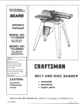
BELT AND DISC
SANDER ONLY
MODEL NO.
113.225930
BE LT AND DISC
SANDER!WITH
LEGS AND MOTOR
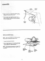
Serial
Number
Model
and serial
number
at the right-hand
of the base.
You
model
C nFTSMR
may be found
should
side
record
both
and serial number
in a safe place for
future use.
BEL T AND
DISC
SANDER
CAUTION:
Read GENERAL
ADDITIONAl.
® assembly
. operating
e repair parts
and
SAFETY
INSTRUCTIONS
carefully
Sold
by
Part No. 68067
SEARS,
ROEBUCK
AND
CO.,
Chicago,
IL.
60684
U.S.A.
Printed in U,S.A,
FULL ONE YEAR WARRANTY
This warranty
gives
you
specific
legal!
ON CRAFTSMAN
rights,
and
you
may
also
BELT AND DISC SANDER
have
other
rights
which
vary
from
state
to
state:,
SEARS.
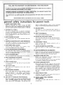
general
ROEBUCK
safety
1, KNOW YOUR
AND
CO.. Dept.
698/731A.
instructions
Sears Tower,
as the
POWER TOOL
specific
2. GROUND
This
toot
mask if cutting
(plugs or muffs}
€o_d arid
potential
equipped
a 3-prong
grounding
type
with
an
grounding
peculiar
to this
in working
plug
tool.
Never
the
Use clamps or a vMse to hold work when practical.
It's
safer than using your hand, frees both hands to operate
tool.
proper
conductor
connect
the
in
green
the
and
14. DON'T
wire
Keep
OVERREACH
proper
footing
15. MAINTAIN
IN PLACE
order,
in proper
adjustment
operation
is dusty,
and ear protectors
during
extended periods of operation.
13. SECURE WORK
3-conductor
to fit
Th =. green
wire,
3, KEEP GUARDS
approved
type
receptacle.
cord
is the grounding
to a live terminal.
-
hazards
ALL TOOLS
is
I L 60684
for power
Read and understand the owner's manual and labels
affixed to the toot, Learn its application and limitations as
well
Chicago,
and
Keep
align-
4, REMOVE
ADJUSTING
KEYS AND WRENCHES
Form
habit
of checking
to see that
wrenches
are removed
from
tool
before
sharp
before
Ciuttered
must
areas
not
and
be slippery
CLEAN
benches
due
inwte
to wax
or
accidents.
Floor
clean
bits,
Make
sure
for
times.
best
for
when
cutters,
and
safest
perform_
and
changing
lubricating
changing
Switch
accessories
such
as
etc.
17. AVOl D ACCIDENTAL
sawdust.
at all
TOOLS
servicing;
blades,
5. KEEP WORK AREA
and
instructions
16. DISCONNECT
keys
and adjusting
turning
it on.
balance
TOOLS WITH CARE
tools
ance.
Follow
accessories.
ment.
and
STARTING
is tn
"OFF"
posntlon
before
plugging
n
6: AVOID
Don't
;_ose
DANGEROUS
them
adequate
.
to
rain.
Keep
visitors
should
well
r ..................
18
tocatio n:::::::::::::::::::::::::::::
USE RECOMMENDED
lighted.
Consult
Follow
P:t6:_i_le ....
.....
The
AWAY
be kept
padlocks,
area
space,,
8. MAKE WORKSHOP
with
work
surroundingw0rk
KEEP CHILDREN
All
ENVIRONMENT
use power tools in :damp orwet
a safe
distance
from
.:
swmtches,
or by
removing
starter
9. DON'T FORCE TOOL
do
the
job
better
Don't
force
safer
at the
rate
for
or
attachment
to
_o
a ?oh
_t was
not
for
wear
loose
{rings,
wristwatches)
NONSLIP
footwear
hall
covering
to
above the elbow.
12, USE SAFETY
clothing,
Check
parts,
dtt=ons
_)art
gloves,
to
get
caught
is recommended.
contain
occur
long
hair.
neckties
or
jewelry
_n moving
pa_'ts
Wear
protective
Roll
long
if
the
tool
is tipped
or
if the
above
or
the
tool
on
near
the
to reach
tool
such
that
part
that
them,
PARTS
sleeves
(Head Protection)
Wear safety goggles (must comply with ANSI Z87.t)
at all
times.
Everyday:
eyeglasses
only have impact
resistant
lenses, they are NOT safety glasses. Also, use face or dust
use of the
tool.
a guard
or
other
should
be carefully
checked
to ensure
that
properly
and perform
its intended
function
it
for alignment
of moving
parts,
binding
of moving
breakage
of parts,
mounting,
and any other
con,
that
may
affect
its operation.
A guard
or other
that
is
damaged
should
be
properly
repaired
or
d_rect_on
of
replaced
21. DIRECTION
Feed
work
rotation
GOGGLES
hazards.
contacted.
materials
to stand
further
=s damaged
will operate
TOOL
too!
could
store
cause
which
11. WEAR PROPER APPAREL
not
not
may
accessories.
accessories.
ON TOOL
is accidentally
_s necessary
Before
10. USE RIGHT
designed
tool
accessorues
20. CHECK DAMAGED
and
_t was desngned
Do
Do
it
I1 wdl
injury
cutting
keys.
STAND
Serious
ACCESSORIES
owner's
manual
for recommended
instructions
that
accompany
the
use of improper
i:::::iii:i
::!9:iNEVER
worl(:area:
KID-PROOF
master
the
the
OF FEED
into
of the
a blade
blade
22. NEVER LEAVE
UNATTENDED
Tu=n
corn
power
_lete
stop
off.
or
or
cutter
cutter
against
the
only.
TOOL RUNNING
Don't
leave
tool
until
it
comes
to
a
Safety
is a combination
alertness
used.
at all times
of
operator
when
the
common
finishing
machine
sense
and
scraps of wood,
related
feed or
planned.
is being
g,
h.
PAGE
General
Safety
2. Getting
Instructions
To Know
3. Basic Machine
4. Maintenance
5. Stability
Your
For Power
Sander
Operation
Tools ....
18
.................
Always adjust the worktable
abrasive disc or belt.
on the abrasive
finishing
on the
to withh_
When finishing a large piece of
is supported
at table height,
21
.........................
23
!/16
i_ of the
9,
6. Location
The machine should be positioned
so neither the operator nor a casual observer is forced
to stand in line with
the abrasive belt or disc. This machine
i:s intended
for
material,
make
sure it
Never leave the machine work area with the power on,
before the machine has come to a complete
stop, or
without
removing
and storing the switch key.
Of Machine
k.
7.
Hold the work firmly
when finishing
belt and against the worktable
when
disc.
2
.............
tf there is any tendency
for the machine
to tip over or
move during
certain operations
such as when finishing
long heavy boards,
the sander should be bolted down.
indoor
the workpiece
and
for the operation
Make sure the abrasive belt runs in the right direction°
Atwayshave
the tracking adjusted correctly
so that the
belt does not run off the pulleys.
WARNING:
FOR YOUR OWN SAFETY, NO NOT
ATTEMPT
TO OPERATE
YOUR
FINISHING
MACHINE
UNTIL
IT IS COMPLETELY
ASSEMBLED AND INSTALLED
ACCORDING
TO THE
iNSTRUCTIONS
. .. AND UNTIL YOU HAVE
READ AND UNDERSTOOD
THE FOLLOWING.
t.
etc.) except for
support
devices
Never operate the machine
with
the unused shaft end of the motor
protective
removed.
cover
If any part of this bett disc sander should break,
or fail in any way or any electrical
component
perform
properly,
or if any is missing, shut off
switch,
remove power supply cord from power
and replace damaged
missing and/or failed parts
resuming operation.
on
bend,
fail to
power
supply
before
use only.
10. Read and follow the instructions
appearing
the front edge of the sanding table,
Kickback
on label
on
When finishing
on the Disc, always apply the workpiece
to the "Down
Side"
of the disc. Applying
the workpiece to the "Up
Side"
could
cause it to fly
up
(kickback)
which could be hazardous.
8. Protection:
Eyes, Hands,
11, Do not hand hotd the workpiece.
Support
it with the
backstop
or worktab}e.
The only exception
is curved
work performed
on outer end of belt (idler pultey),
Face, Ears, Body
a. Wear safety goggles that comply
with ANSI Z87.11968, and a face shield if operation
is dusty. Wear
ear plugs
tion.
b. Do not
hand.
c. Avoid
could
belt.
or muffs
finish
extended
pieces of material
too
periods
of opera-
small to hold
by
awkward
hand positions,
where a sudden slip
cause a hand to move into the abrasive disc or
d, Never climb
e,
during
on the machine.
Never turn your
table(s)
or work
1
Sander "'ON"
before clearing
the
surface(s)
of all objects (tools,
12, Do not get fingers near the in-running
nip of dust trap
or section of belt where it enters the dust trap,
13. Think
Safety,
CAUTION:
This machine is not designed for heavy
deburring operations. When finishing ferrous metals, sparks will be generated and could cause a
fire. Disconnect any type of dust collecting hose
from the machine. Also remove all traces of wood
dust that may have accumulated inside the dust
traps in the machine.
additional safety instructions
for belt and disc sander
WARNING: THE 2:1/2" MACHINE PULLEY AND
THE 2" MOTOR PULLEY FURNISHED,
WILL
RUN THE DISC AT APPROXIMATELY
2700
RPM AND THE BELT AT APPROXIMATELY
2100 (FEET PER MINUTE) WHEN USED WITH A
3450 RPM MOTOR. NEVER SUBSTITUTE
OR
INTERCHANGE THESE PULLEYS TO INCREASE
THIS SPEED BECAUSE IT COULD BE DANGEROUS.
i
...........................
WARNING:
DO NOT ALLOW FAMILIARITY
(GAINED
FROM FREQUENT
USE OF YOUR
MACHINE) TO BECOME COMMONPLACE,
ALWAYS REMEMBER THAT A CARELESS FRACTION OF A SECOND IS SUFFICIENT
TO INFLICT SEVERE INJURY.
.................
WEAR YOUR
The operation
of any power too! can result in foreign
objects
being thrown
into the eyes, which
can result in
severe eye damage, Always wear safety goggles complying
with ANSI ZB7.1 (shown on Package) before commencing
power tool operation: Safety Goggles are available at Sears
retail or catalog stores.
H
:•
'
motor specifications
and
This machine ;s designed to use a 34,50 RPM motor
Do not use any motor that runs faster than 3450
eledricat
only.
RPM.
This
power
tool
i_ eqLJipped
groundmg
tV_;
by Underwriters'
It {s wired for operation on 110420
volts, 60 Hz, aite__
nating
current,
iT MUST
NOT BE CONVERTED
TO
OPERATE
ON 230 VOLTS_ EVEN THOUGH
SOME OF
THE RECOMMENDED
MOTORS ARE DUAL VOLTAGE.
THESE CRAFTSMAN
MOTORS
FOUND
TO BE ACCEPTABLE
THIS TOOL,
requirements
As'¢ociation.
is attached
prong
HAVE BEEN
FOR USE ON
with
The
to the
3450
3450
3450
3450
110. t20
110-120
1!0-120
11O,120
in the attachmer_t
This
plug
requires
outlast as shown.
1216
1218
1219
1226
adapter
known
It
plt,g
a
CAUTION:
Do not use blower or washing machine motors
or any motor with an automatic
reset overload protector
as their use may be hazardous,
CONNECTING
is
as shown
gro_and,
at the Other
mating
from
the
tha!
as shown
receptacie,
adapter
must
while
type
you
have
outlet
grounding
the
a qualified
with
)ug
tO
eiectrician
a proper!*,,
grounded
is available
for cOnr'ecting
plugs
green
gr'oundmg_t_g
extending
be connected
grounded
to a permanent
outlet
ground
box.
in use to protect
Plug power
cord
into
a 110.120V
properiy
out_et
protected
by a 15_amp.
dual element
Circuit.Saver
fuse or circuit
breaker,
If you are not sure that your
have it checked by a qualified
_ grounded
to use for this power
tooi
is
NOT
REMOVE
OR
ALTER
IN ANY
MANNER.
Use an
connect
tx.qow
s. The
slach a,_ to a proL,_erly
This machine
must be grounded
the operator from electric shock.
and
end.
3-conducto.
always
the
TWO
prong
prong
OUtlet,
An adapter
to 2-prong
TO POWER SOURCE OUTLET
and
recommended
replace
THREE
cold
_pp_oved
Standards
ground
conductor
has a green ie..¢ket and
toot housing
at on_ end af_d to the ground
If the outtet
yot_ are planning
o¢ the
two
prong
tYi:_
DO
THE
GROUNDING
PRONG
t/2
t/2
3/4
3/4
a 3.conductor
_))Ug which
has a grounding
prong,
Labora!or}es
arid the Canadian
grounded
type
time delay
or
outlet is properly
electrician,
grounded,
WARNING:
DO NOT PERMIT FINGERS
TO TOUCH THE
TERMINALS
OF PLUGS WHEN INSTALLING
OR REMOVING
THE
PLUG
TO OR FROM
THE OUTLET.
WARNING:
IF
NOT
PROPERLY
GROUNDED
THIS
POWER TOOL CAN INCUR THE POTENTIAL
HAZARD
OF ELECTRICAL
SHOCK. PARTICULARLY
WHEN USED
IN DAMP LOCATIONS
IN PROXIMITY
TO PLUMBING.
IF AN ELECTRICAL
SHOCK OCCURS
THERE
IS THE
POTENTIAL
OF A SECONDARY
HAZARD
SUCH AS
YOUR
HANDS
CONTACTING
THE ABRASIVE
BELT
OR DISC.
tf power cord is worn
it replaced immediately.
or cut, or damaged
If your unit is for use on
that looks like below.
less than
NOTE: The adapter illustrated
is for use on}y }f you already
have a properly
grounded
2-prong
receptacie.
Adapter
is
not allowed
in Canada by the Canadian Efectricat
Code.
The
of
To
any
extension
keep
this
heating
and motor
mine the minimum
inany wav, have
150 volts
use
power.
only
3 wire
type
plug.
plugs
to
burn-out,
wire
size
extenSiOn
and
cord
cords
3-poie
wili
a minimum
use the
(A.W.G.)
which
receptacles
son_
cause
and
to
table below
extension
have
of
over-
to detercord,
Use
3.prong
which
loss
prevent
grounding
accept
the
_oo}s
it has a plug
Extension
Co_d
Length
Wire
Size
A.W.G,
Up to t00
Ft.
t6
I00,200
Ft,
14
400 Ft.
!0
200-
3-PRONG
PLUG
CHECK
MOTOR
ROTATION
WARNING:
FOR YOUR
OWN SAFETY,
MAKE
PLUG IS NOT CONNECTED
TO POWER SOURCE
LET. WHEN CHANGING
MOTOR ROTATION.
GROUNDING
PRONG
The
motor
from
pulley,
[See
according
5
must
viewed
the
page
to
the
rotate
shaft
tt)
SURE
OUT-
COUNTERCLOCKWISE
end
H it
instructions
to
does
which
not,
furnished
when
w_{{
you
change
with
n'_Ount
the
the
th_
d:_ec-_io_
,q_Ot_:_r
CONTENTS
BeltTable
Lockifiq Bolts
. .....................
Belt Table Stop
............................
BASIC OPERATION
..........................
19
19
20
Surface Finishing on the Abrasive Belt ...........
End Finishing on the Abrasive Belt
. ............
Finishing Curved Edges on the Abrasive Belt ......
Finishing Small End Surfaces
and Curved Edges on the Disc
MAINTENANCE
.............................
Installing Belt Dust Trap
....
. .. ..............
: : Imtalling:Backst0
p , y:=:..:..;...
......
... ......
GETTINGTO
KNOW YOUR SANDER
. : ....
: .....
18
18
18
Backstop
19
Lock Screw
........................
unpacking
................
21
22
Wiring Diagram
............................
LUBRICATION
...............................
TROUBLE
SHOOTING
........................
Recommended
Accessories
...................
REPAIR
PARTS
..............................
PARTS
LIST
................................
16
17
17
Belt Adjusting Screws
.......................
Belt Locking:Screws
.........................
WorkTable
Tile LOck Screw
..................
20
20
21
22
22
23
23
24
25
contents
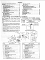
and checking
TOOLS
Model
113.225900
Belt
and
Disc Sander
is shipped
complete
inone
carton
but DOES NOT INCLUDE
Steel
Legs or M0tor.
1/2"
7116"
3/4"
318"
Model:
t13i225930
Belt
and
Disc Sander
is shipped
complete
in one carton
and INCLUDES
Steel Legs and
Motor,
Separate aif parts from packing materials and check each
item With illustration
and 'q'able
of Loose Parts," Make
certain all items are accounted
for, before discarding
any
Wrench
Wrench
Wrench
Wrench
NEEDED
_/_2 Phillips Screwdriver
COMBINATION
SQUARE
MUST BE TRUE.
%
THIS
STRAIGHT
EDGE
OF
ROARD
3/4 '_ THICK
•
DRAW
LIGHT
LINE
ON BOARD
ALONG
_ ....
I '_
THIS
EDG
EOGE
PERFECTLY
MUST
8E
STRAIGHT
pack ing material.
If any parts are missing, do not attempt
to assemble the
Belt and Disc Sander, plug in t'he power cord, or turn: the
switch
on until
the missing
parts are obtained
and
installed correctly.
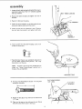
using a t/2,
the machine,
wrench,
remove the plywood
attached
to
Save the nuts and bolts and washers. You
will need them for attaching
the machine
to the base.
C
A-_
B ,,,_,,_
_-:t
Item
Table of Loose Parts
2
•
Item
Qty.
0
P
Q
R
-
5/32 Se_crewWrench
: ..................
Flat Head Machine Screw 10-32 x 1-3/4
S
T
U
V
W
X
:
: .....
......
F
"-..
,
i1
1
4
6
Qty.
i, i
Pan Head Screw, Type 23 8-32 x 3/8 .........
Fiat Washer, 21/64 x 7/8 x 1/8 ..............
Hex, Head Machine Screw 5/16-18 x I ........
Screw, M Pan Hd. 10-32x 9/16
.............
L0ckwasher No. 10 Int. Tooth ..............
1
1
1
t
1
1
3
:3
Base and Belt, Table (w/Sanding Belt). .....
:....... :11:
OisCOustTrap:
:'::-::-'-i-:,:
:-- .... :':::::
:DuSt Trap C0:ve:r . : .... ... .... ; :. .... : .....
I:
Bag (c0ntainingthe
following loose parts)
(Part No: 68035)
MotOr Pulley, 2In. Dia. _....
:....
....
E
Table of Loose Parts
ii
V-Belt, 1/2 x 41"
, .........................
Backstop ...............................
Beff, Dust Trap ..........................
Motor Putley Belt Guard ...................
Belt Guard Support .......................
Bert Guard Support Bracket ................
"S" Clip
...............................
.
Pan Head Screw, Type 23, t0:32 x 1/2 .: : :.;:.:
D
\_
Hanger, Cable ...........................
Owner's Manual ...........................
9" Abrasive Disc ..........................
Sanding Disc (w/Set Screw) ..................
Belt, Sanding ..............................
Bag Assembly, 0 utlet (Part No. 68064}
(containing the following loose parts):
Outlet, on/0ff Power ......................
Switch Key . .. ..........................
Bracket, Switch Mounting ..................
Screw, Pan Hd, 8 x 3/8 ....................
Lockwasher, 1/4"
Screw; Pan Hd. Machine 1/4-20 x 1/2 .........
5
1
1
1
1
t
1
1
1
1
1
1
!
3
2
2
assembly ;........
The following
ONLY.
.
parts
:
ar e included
with
Model
1t3.225930
H
Item
No.
O.ty.
* Loose PartsBagPart-#68062 Containing FollowingItems:
* A Nut, Hex Head 1/2-t3 ..................
* A Nut Hex 1/4-20 .......................
* B ScrewTrussHd. 1/4-20 xF/8 ............
* C L0ckwasher,1/4 External ...............
* D Foot, Leveling ........................
E Motor ...............................
F Leg .................................
G Channel,Support ......................
H Stiffener, Side ........................
J Stiffener, End ........................
K Support, Motor .......................
8
32
32
32
4
1
4
2
2
, 2
1
G
HARDWARE FOR MOUNTING TOOL & MOTOR
* L Screw, Hex Hd. 5/16-18 x 2 1/2 ..........
* C Lockwasher Ext. 5/16 ...................
*A
Nut, HexS/tG-18 ......................
* M Washer11/321D ......................
* N B01t,Carriage5/16-18 x 3/4 .............
2
6
6
6
4
©
M
A
B
C
D
END
STIFFENER
HEX
NUT
l
_,.,. LOCKWASHER
END
ASSEMBLING
STEEL LEGS
(MODE L 113.225930 ONLY)
SIDE
STIFFENER
i
i
o
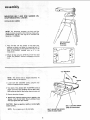
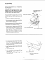
Assemble
the two (2) End Stiffeners
and the two (2)
Side
Stiffeners
using four
(4) 1/4-20
Truss
head
screws. The End Stiffeners
are placed on top of each
Side Stiffener
as shown,
insert screws through
the
9/32
inch diameter
holes and finger tighten
1/4-20
nuts.
1,
.
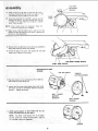
3. Remove
the
four
(4)
Truss
head
screws
which
SCREW
\
were
assembled
in Paragraph
No. One. Place the two (2)
Support
Channels as shown, in position,
align holes in
supports
with
holes
in the Stiffeners,
replace
!ockwashers
wren ch.
and
nuts.
Tighten
all nuts
using
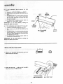
MOTOR
SUPPORT
7/16"
4_
Assemble the motor support
to steel legs with 1/4-20
screws and nuts. Motor support
can be mounted
to
either end of stand. Tighten
nuts,
5.
Install leveling feet as shown. To level Leg Set, loosen
nut on inside of leg and turn nut on outside to raise
or lower
feet. Adjust
all four levelers, if necessary,
and then tighten nuts on inside of leg.
1
SCREW
NOTE:
These
adjustment.
levelers
are not
intended
for
LEG
CHANNEL
SUPPORT
Attach
the four (4) legs to the side and End Stiffener
using 1/4-20 screws, IockwasherS and nuts as shown.
height
7
_
bly
_
2
MOUNTING
BELT AND DiSC
CRAFTSMAN
STEEL LEG SET.
CATALOG
SANDER
ON
NO,_ _22236-
NOTE!: =FOr illustrative purposes, the Belt and Disc
Sander=isshown mounted on the Craftsman Catalog No.
9-22236; Steel Leg set. This Leg Set is included with
Model No. 113.225930.
/
1_ Place the
Belt
and
Disc
Sander
on the
Steel
MOTOR MOUNT
BRACKET
TH IS SI DE
Legs,
position
as shown, and align the mounting
holes in
the feet of the Belt and Disc Sander with those in the
END
STIFFENERS
(marked
with
an X in the
ilhJstration}.
2,
MOunt
to
screws,
nuts.
legs using two 5/I6-t8
flat
washerS,
external
x 2-1/2"
hex head
fockwaShers,
and
hex
1/2"
NOTE:
The abrasive
belt is shipped
install the belt on the machine:
detached.
WRENCH
To
PAPE R
t.
Loosen
both
wrench
furnished
2. Turn
both
belt
LOCKING
with
they
ING screws so that
using
the
1/2"
tt_e machine;
of the abrasive belt
shown until
3. Remove
screws,
AJUSTING
stop. Retighten
the idler
pulley
the two
screws
belt
as
LOCK-
does not come out
the piece of paper.
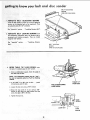
4. Remove the protective coating, that is applied at the
factory, from the belt tabte. Use any ordinary household type grease and spot remover.
CAUTION:
volatile
Never use gasoline, naptha,
or similar
highly
solvents.
NOTE:
Do not apply
wax tothe
belt table.
BELT
/
ADJUSTI
(ONE
ON EACH
NG SCREW
SIDE)
BELT
LOCKING
SCREW
(ONE
ON EACH
SIDE)
assembly
I.
Loosen the belt table locking bolts
ing bracket using one of the i12"
with
behind the mountwrenches
supplied
your machine,
JBELT TABLE
2, Position belt table
the bolts.
3. Place the V-Bett
vertically
and tighten
only
LOCKING
one of
over the pulley,
!NCH
4. Attach
the switch
assembly
screws and washers
5.
Loosen
the
belt
the bolt
table
packed
that
tO the base using the two
with
the switch.
you tightened
horizontally,
in step
and tighten
2. Position
both
bolts.
SWITCH
ASSEMBLY
6.
Find five 3/8"
Pan Head
among the loose parts,
Self-Treading
screws
from
3/8"
7. Place Disc Dust Trap on your workbench
and screw in
five Pan Head "Thread
Cutting
Screws,"
3/8" long.
Screw them
NOTE:
screws
thread
in all the way,
The holes in the Trap are not
are "Thread
as they
Cutting
threaded
Screws"
but the
and wilt
cut
a
are tightened.
DISC
B. Find four Flat Head Machine
among the loose parts
Screws
1-¾"
long from
FLAT
HEAD
t 3/4"
LONG
DUST
TRAP
FLAT
SPOT
SCREWS
ON SHAFT
!_
9, Attach
the Disc Dust
1-¾" long.
t.3/4'
Trap
with
four
flat
head screws
10. There is a flat spot on the shaft near the end, Rotate
the shaft so that the flat spot is facing up.
5/32 INCH
SETSCREW
WRENCH
1I:
Pia_
:tthel dis:€ on:the
shaft
so that
the set screw
facing Up, PbSition::the disc: so that it is approx
:: i_chOutwa[d;
f_6m:_(heedge
of the dust trap.
is
I/1 6
DU
TRAP
,etscrewwrench
tli_oUgh tlSe h01e in the disc housing and into the
s_etscrew :in =tl_e: disc: Make sure Setscrew is aligned
•
t_ Flat tw on sha f t,
w=th
NOTE::i:After
several hoUr_ of Operation,
looseness of setscrew and retighten.
13.
Make
certain
that
the
metal
disc
grease then peel the backing from
and:affix
to the sanding disc.
check
is free
the 9"
of
for
oil
and
abrasive
disc
14_ Remove the top right hand screw which you installed
step 6and loosen the other three screws.
15, install
the Dust Trap cover and replace
hand screw. Tighten
all five screws.
the
top
\
t
\
in
right
\
DUST
TRAP
TOP
RIGHT
HAND
SCREW
COVER
MOTOR BASE CLAMP
SCR EWS
5/8"'
DIA.
SHAFT
CUTTING
THREAD
1. Place the motor on your workbench
shaft (wit h key wav)facing
you,:
::
i ¸H- • • i
" • /•
• •i : ••
2. Loosen :the two motor base clamp
the motor
so that the ventilation
the side..,
tighten
with
the 5/8
SCREWS
D ia.
screws and rotate
holes are facing to
the screws.
I
BELT
GUARD
SU PPO RT
BRACKET
BELT
GUARD
SUPPORT
i
ii
3. Attach guai'd Support to the bracket with the two
screws furnished with the belt guard;
NOTE:
but
The
holes in the bracket
the screws:are
Cut a_thread
°'thread
ag:thev-are
cutting
tighted_:.
are not
threaded,
screws"
and will
:
SCREWS
10
assembJy
4.
Loosen
setscrew
i n motor
pufley
and place the pulley
DIRECTION
OF
ROTATION
on the shaft with the hub flush with the end of the:
shaft, insert the motor shaft key and tighten setscrew
with 5/32" setscrew wrench.
5/32
INCH
SETSCREW
CHECK
MOTOR
The motor
must
viewed from the
1. Place the
motor
WRENCH
ROTATION
rotate COUNTERCLOCKWISE
PULLEY
end.
on your
2. Stand ctear of the motor
properly
grounded
outlet
rotation
of the pulley.
If
CLOCKWISE,
REMOVE
and change the rotation
the instructions
furnished
workbench
\
when
or on the floor.
and plug the cord into a
(See page 5). Notice the
it is not turning
COUNTERthe plug from the outlet,
of the motor
according
to
with the motor.
FLUSH HERE
MOTOR
SHAFT
KEY
WARNING: FOR YOUR OWN SAFETY, MAKE
SURE PLUG IS NOT CONNECTED TO POWER
SOURCE OUTLET.
1.
Find four 5/16" - 18 x 3/4" carriage bolts,
lock washers and nuts supplied with base.
fiat washers,
3/4"
f
[4--9/t6"'-_
i
/
BRACKET
MOTOR
MOUNT
-._.,_/
2. Attach motor by inserting carriage bolts through slots
in motor base and then through
slots marked "X" in
motor
mount
bracket,
then place flat washers and
Iockwashers
on each bolt ... screw on nuts but DON'T
TIGHTEN
them.
VENTILATION
HOLES
FACING DOWNWARD
tl
D
_:D
r_l
o sombly
BELT
the round opening.
MAKE:SURE
BELT HAS NOT SLIPPED OFF OF
MACHINE PULLEY.
/
CLIPS
(SET 90 ° APART)
6. Place the bett onto the motor pulley by rotating the
pulley.
7. Snap the belt guard into position.
\
8_ Move the motor sideways so that the belt is in the
center of the opening in the top of the base.
=
BELT MU3T BE ON
MACH INE PULLEY
9, PUSH downward on motor to apply tension to belt
.... and itighten-motor bolt nuts.
NOTE: It is only; necessary to tension the belt so
that itdoes
not slip while running,
lO_i, lf,_::you cannot, Obtain rl,
sufficient,_tensiOn with,the
motor pushed all the way down, remO_ie the four
motor bolts and insert them in the next LOWER set
of holes.
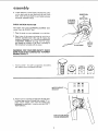
ON-OFF SWITCH
WARNING:
DON'T CONNECT POWER CORD
TO ELECTRICAL
OUTLET
IN YOUR SHOP
UNTIL YOU ARE READY TO CHECK MOTOR
ROTATION.
The On_)ff Switch has a locking feature. THIS FEATURE
IS INTENDED
TO PREVENT
UNAUTHORIZED AND POSSIBLE HAZARDOUS USE BY CHILDREN AND OTHERS.
t. Insert key into switch.
NOTE: Key is made of yellow plastic
12
assembly
2. To turn machine on, insert finger under switch lever
and pull end of switch out.
3. To turn
Never
machine
OFF
leave the machine
to a complete
...
PUSH lever
unattended
until
in.
it has come
stop.
4. To lock switch in OFF position..,
hold switch IN
with one hand . . . REMOVE key with other hand.
WARNING:
FOR YOUR OWN SAFETY, ALWAYS LOCK THE SWITCH "OFF"
WHEN
MACHINE IS NOT IN USE ... REMOVE KEY
AND KEEP IT IN A SAFE PLACE...
ALSO
. . . IN THE EVENT OF A POWER FAILURE
(ALL OF YOUR
LIGHTS GO OUT)
TURN
SWITCH OFF.-.
LOCK ITAND REMOVE THE
KEY. THIS WILL PREVENT THE MACHINE
FROM STARTING
UP AGAIN WHEN THE
POWER COMES BACK ON.
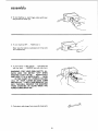
5. Find plastic cable hanger from among the loose parts.
13
CABLE
_HANGER
MOTOR
j
CORD
6, Route
the motor cord behind the motor
mount,
across the top, of the base and plug it into
the
receptacle in the side of the switch box.
7. Bring
wrap
the power cord alongside
the motor cord
the plastic cable hanger around the cords
attach the hanger to the top
it into a _" diameter hole.
INSTALLING
of the
. . .
and
base by pushing
WORKTABLE
NOTE:
Apply coat of paste wax tothe
work
This will make it a little easier to feed the work,
table,
1. Loosen the table positioning screw.
2, Insert the table support
rod in the hole in the base
until the edge of the table is approximately
|/16"
from the abrasive disc. Tighten the screw.
NOTE:
There is a second mounting
is for mounting
the:table
when
hole in the base. This
the belt isused :in a
ver-
tical position.
SECOND
MOUNTING
HOLE
: ;:,
_
,:
:
::: i_
14
TABLE
POSITIONING
SCREW
TABLE
SUPPORT
ROD
assembly
INSTALLING
ABRASIVE
AND TRACKING
BELT-TENSIONING
WARNING: FOR YOUR OWN SAFETY, TURN
SWITCH "OFF"
AND REMOVE PLUG FROM
POWER SOURCE OUTLET BEFORE REMOVING OR INSTALLING ABRASIVE BELT.
PULL WRENCHES
DIRECTION
TENSION
DIRECTIONAL
IN THIS
TO APPLY'
ARROW
On the smooth side of the abrasive belt you will find a
"directional
arrow."
The abrasive belt must run in the
direction
of this arrow so that the splice does not come
apart.
1, Loosen the two abrasive belt LOCKING
screws.
2. Place the abrasive bett over the pulleys with the directional arrow pointing
as shown. Make sure the abrasive belt is centered on both pulleys.
Turning
the abrasive belt ADJUSTING
screws will cause
the idler pulley to move in or out. When the idler pulley
is moved outward,
it puts TENSION
on the belt.
3. Place both of the 1/=-wrenches on the ADJUSTING
screws and pul! the wrenches toward you. This will
stretch the abrasive belt. Move the wrenches back and
forth a few times so that you "get the feel" of the
abrasive belt while
it is stretching
(TENSIONING).
BELT ADJUSTING
SCREWS
BELT
LOCKING
SCREW
Apply a small amount of TENSION
to the abrasive
belt by pulling
the wrenches toward you, so that the
TENSION
feels the same on both wrenches.
ii
4.
iJJl
iJ
Hold the abrasive disc with your left hand to keep it
from turnin'g while
pushing the belt in the direction
of the arrow.
If the abrasive
belt slips over the
pulleys,
turn
both
ADJUSTING
simultaneously
a small amount to apply
tension to the abrasive belt.
screws
a little more
5. Adjust the tension so that the abrasive belt does not
slip very easily when pushing it, while you are holding
the disc,
6. Tighten
7.
the locking
screws.
Plug in the power cord. Turn the switch "'ON", and
immediately
"'OFF", noting if the bett moved to the
right or to the left.
If
it did
not move
TRACKING
to
the
right
or
left,
it
is
PUSH BELT
properly,
tN DIRECTION
OF ARROW
15
....=
].
.......
....c.=_-_._
.............
as,sembly
MOVES
a::: Loosen the LOCKING
hi:i: Place Wrench on
SCREW
TO
THE
on the RIGHT.
the ADJUSTING
SCREW
on the
LEFT
c;: :Push abrasive belt so it is moving while pulling the
: wrench towa:td you!:: This wiil move the abrasive
be|t to the {eft. PUSHING
the wrench will move
BELT
MOVING
TO RIGHT
the belt to the right,
d.
The abrasive
centered on
belt is tracking
the DRIVE
IMPORTANT:
If you
abrasive belt, apply more
9.
IF THE
a.
ABRASIVE
have difficulty
tension.
BELT
Loosen the LOCKING
b. Place
left.
wrench
c. : Push:'abrasiW
properly
pulley.
MOVES
SCREW
when
tracking
TO THE
it is
RIGHT
the
BELT
LOCKING
SCREW
LEFT:
on the LEFT.
on the ADJUSTING
belt so it is moving
SCREW
while
on the
wrench toward
you, This will move the abrasive
belt tO:the :tight, PUSHING
the wrench will move
the abrasive beit to the left.
d.
The abrasive belt is tracking
properly
Centered on the DRIVE
pulley.
IMPORTANT:
If
you
have difficulty
abrasive belt, apply more tension_
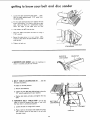
INSTALLING
BE LT DUST TRAP
1. Find one 10-
32 x 9/16"
when
tracking
it
DRIVE
PULLEY
BELT ADJUSTING
SCREW
pulling the
is
the
©
Pan Head screw and a lock-
washer among the loose parts.
2. Attach the dust trap . _. make sure the top edge is
below the surface of the abrasive belt,
PAN HEAD
AND
16
SCREW
LOCKWASHER
BELT
DUST
TRAP
a S$e rn _ _y
BACKSTOP
LOCK SCREW
INSTALLING
1. Find
one
washer
BACKSTOP
BACKSTOP
5/16"
among
x 1"
the
Hex.
loose
Head
bott
and one flat
parts.
2. Place the washer on the bolt, and screw it halfway
into the mounting
hole, Place the backstop
into postion and tighten the bolt. When removing
the backstop, loosen the bolt but do not remove it.
,
ii
i,i
,i........
, uuJ_LJ_,
, ipp ..............
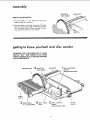
getting to know yourbeJt
and disc sander
WARNING:
FOR YOUR OWN SAFETY TURN
SWITCH "OFF" AND REMOVE PLUG FROM
POWER SOURCE OUTLET BEFORE MAKING
ANY ADJUSTMENTS,
ABRASIVE
DISC
4
BACKSTOP
BELT
BACKSTOP
ADJUSTING
SCREW
(ONE ON EACH
SIDE)
LOCK SCREW
WORK
TABLE
' 3WO.KTABLE
TILT
LOCK SCREW
BELT TABLE
BELT
STOP
SCREW
(ONE
17
LOCKING
ON EACH
IDLER
PULLEY
SIDE)
know your beret
s n er
BELT
ADJUSTING
SCREW
(ONE
I_ AB
_/E::BELT
:catJse
:ADJUSTING
:dier pUiiey:i to:m0ve
ter_sion:to theab_asive
are adjusted
heft or for
using the 112"
see _'Assembly"
BELT
the adjustment
See "assembly"
\
for appiylng
tracking
it: They
"1 nsta!ling Abrasive
LOCKING
mechanism
tensioned
an,d tracking
USihg the i/2': :wrench.
after
Belt".
SCREWS lock
the abrasive
properly.
They
are
section . . . "Installing
belt is
locked
/
Abrasive
Belt".
BELT LOCKING
SCREW
(ONE
i
.: 3, ¸
SIDE)
wrenches,
section...
2. ABRASIVE
SCREWS
in::0r:out
ON EACH
i
WORK TABLE
TILT
ijjl
LOCK
i
SCREW
ON EACH
SIDE)
] i _,
locks
l_e table. It is locked using the 1/2" wrench.
a; Using a combination
square,
the table witch the disc:
check the angle.of
NOTE:
The combination
square must be "'true"-See start of assembly section on Pg; 6 for checking
method.
b. If the table
is not 90 ° with
the disc ...
c, Loosen the lock nut using a 7/16"
TABLE 1/2"
FROM DISC
loosen
tilt lock screw and tilt table,
wrench.
TABLE POSITIONING
LOCK SCR EW
d. Screw the stop screw in or out, using a 318"
wrench so that when the table touches the stop
screw, the table is 90 ° to the disc,
e. Tighten
the lock nut.
STOP
SCREW
LOCK
NUT
I
TI LT
LOCK
SCR EW
gettincj 1toknow your belt and disc sander
f.
Loosen the table positioning
tion the tab]e approximately
the abrasive disc.
lock screw,,,
1/16"' away
posifrom
g. Tilt the table dov_nward
but don't tighten the lock
screw, and position
it as close to the disc as possible.
Using the head of a combination
square,
check
the angle
of the table
with
the disc.
h. If the table is not 45 ° with
i.
Raise the table
7116" wrench.
j.
Screw the stop screw
in or out, using a 3/8"
wrench so that when the table touches it, it is 45 °
with the disc.
k, Tighten
and
the disc:
loosen
the
lock
nut
using
a
the lock nut.
LOCK
NUT
STOP SCREW
--
.J_,,____
l!ll
,____11
,
,
_LI!
llJ
1'11'
,
I
,
I
'
iii
.,
"n_'l
I'
11111
_£U
BACKSTOP
BACKSTOP
LOCK SCREW
\
\
4.
BACKSTOP LOCK SCREW
place, it is locked
using
locks
the 1/2"
the
, ,,
5. BELT TABLE
backstop
in
wrench,
i, i
LOCKING
BOLTS
,iiii,i,,i,,. ,
...
iiiii,i
,i
iIi
lock the
belt table in position.
To adjust
to vertical
position:
a.
Remove the backstop,
b.
Loosen the two belt table locking boffs using the
1/2" wrench supplied with your machine.
c.
Position
belt
table
vertically
and tighten
the two
bolts.
6. ABRASIVE
BELT TABLE
STOP
can be adjusted so that the abrasive belt table is level with
the floor when in a horizontal position,
a.
Loosen the lock
wrench,
LOCKING
BOLT
STOP
nut using a 314" wrench.
b. Place a level on the abrasive
3/4""
BE LT TABLE
screw
the stop
belt
bolt
table and using
in or out
a
LOCK
until
the table is level.
lg
NUT
BOLT
\
FLA'r SUR
Hoi=d::the:woi_k piece firm|y: with:both
hands, keeping
firtgersaway from the abrasivebelt.
Keep the end butted against the backstop and move the
work evenly across the abrasive belt. Use extra caution
• when finishing Very=thln pieces.
For fihishing long pieces, remove the backstop.
Apply only enough pressure to allow the abrasive belt
to remove material If the abrasive belt stalls and the
belt pulleyS slip white=applying moderate pressure to
the wo_kpiece, the abrasive belt requires more tension.
END FINISHING
ON: THE
tt ismore convient to finish the ends of long workpieces with the: abrasive: belt in a vertical positiom
Move the work evenly across _e
accuracy, use a miter guage.
abrasive belt. For
The table may be tilted for beveled w0rk.
See Getting To Know Your Finishing Machine Section
for adjusting the abrasive belt table and the work table.
• : 20
\
\
\
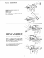
basic operation
FINISHING
ABRASIVE
CURVED
BELT
EDGES ON THE
CURVED EDGES
Finish
outside
curves
on the
curves
on
the
abrasive
belt
and
inside
idler pulley.
FINiSHiNG
SMALL
END SURFACES
CURVED
EDGES ON THE ABRASIVE
AND
DISC
SQUARE
MITER
Move the work across the "Down Side" of the face of
the abrasive disc. For accuracy, usea miter gauge.
NOTE: Use a combination square to square the miter
gauge to the face of the disc. If it is not square, pull out
the index pin, loosen the miter gauge knob and move the
miter gauge s]ightly until it is square. Without moving
the miter gauge,tighten the knob securely.
Applying the workpiece to the "Up Side" could cause it
to fly up (kickback) which could be hazardous.
The table may be tilted
for beveled
work.
2t
GAUGE
wAR_iNG:_ FORiYOUR OWN SAFETY,: TURN
:::SWITCH _ OFF,'IANDREMOVE:
PLUG FROM
POWER SOURCE OUTLET BE FORE ADJUSTs: ING,: : MAINTAINING;
;OR' :LUBRICATING
YOUR: FI NISHING MACH INE:_
Keep:your machine and your Workshop clean. The dust
traps around the abrasive disc and the abrasive belt are
designed t0 deflect most Of the fine dust. They should
connected to a Home-N-Shop Vac for most efficient
dust removal:
WARNING:
DO NOT ATTACH A HOME-NSHOP VAC
WHEN
FINISHING
IRON
OR
STEEL. THE_SPARKS
COULD IGNITE THE
DEBRIS AND CAUSE A FIRE.
if powercord
iS W0rn or:cut,
or damaged
in any way,
have it replaced immediately.
Frequently blow out any dust that may accumulate
inside the motor.
For motor maintenance, follow instructions furnished
with motor.
Acoat of automobile-type wax applied to the worktable will make it a littte easier to feed the work while
finishing.
Donor apply wax tothe abrasive belt table because the
belt could pick =up the wax:and deposit it on t_e pulleys,
causingthe'belt to slip.
lubrication
The BALL BEARINGS
in this machine are packed with
grease at the factory_ They require: nofurther
lubricatiOn.
Periodically
lubricate
pulley mechanism
For
motor
the
with
lubrication,
cams and shafts in the
Silicon
idler
Spray.
follow
instructions
furnished
with motor.
i _ • /:, :/_
_ _,
_ 122
i ¸ :
:
i•
i;
;
:::
_:
:
_
;H
• ,
;:: :
::
;
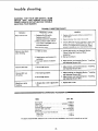
trouble
shooting
WARNING:
FOR
SWITCH "OFF"
POWER SOURCE
SHOOTING YOUR
YOUR OWN SAFETY, TURN
AND REMOVE PLUG FROM
OUTLET BEFORE TROUBLE
SANDER.
TROUBLE
TROUBLE
SHOOTING
REMEDY
PROBABLE CAUSE
Motor will not run.
1. Defective On-Off switch.
Defective switch cord.
3. Burned out motor.
Machine slowsdown
i
.
u ,,,,,,,,,,,_ ,
2. Applying too much pressureto
workpiece.
3. Too much tension on abrasive
belt,
,....
2.
Reset protector
,, ,,,,,,,,,,J
parts before
after
motor
using belt disc
has cooled,
3, Consult Sears Service. Any attempt to repair this
motor may create a HAZARD unless repair is
done by a qualified service technician. Repair
service is available at your nearest Sears Store.
,,, ,,,.
1. V-Belt too loose.
when finishing,
ii
Repface defective
sander again.
"j.
Defective switch box receptacle.
2, Motor protector open, (only if
your motor is equipped with an
overload protector).
i,i
CHART
i,l,,i
, ,,,,
,,,,,i
,L,i
!. Increase belt tension, seeAssembly Section,
"Motor Pulley Belt Guard and Motor
Installation."
2. Ease up on pressure.
3, Adjust tension, seeAssembly Section, "Installing
and Adjusting Abrasive Belt."
,,1,,,..................
,Ji,J
Abrasive Belt Slips
1. Not enough tension.
1. Adjust tension, seeAssembly Section, "Installing
and Adjusting Abrasive Belt."
Abrasive Belt runs
1. Not tracking properly.
1. Adjust tracking, see Assembly Section, "Installing
and Adjusting Abrasive Belt."
2. Adjust tension, seeAssembly Section, "installing
and Adjusting Abrasive Belt."
off pulleys.
2. Not enough tension.
Wood burnswhile
finishing.
......
;
1, Abrasive disc or belt isglazed with
sap.
-m-=_==_RECOMMENDED
1. Repi_e disc or belt,
ACCESSORIES
ITEM
......
'
--
CAT. HO.
Steel Stand
..............................
Caster Set .......................
Miter Gauge
.............................
Pressure-Sensitive
cement
....................
Abrasive Belts and Disc ..............
Steef Legs ...............................
Power Tool Know How Handbooks
Radial Saw ..............................
Table Saw
..............................
9-22213
9-22221
9-29929
9-2220
SEE CATALOG
9-22236
9-22222,
9-2917
9-2918
The above recommended accessories are current and were avai{able at the time this manual was printed.
23
i
23
20:
2
1
3
4
12
65
/
15_
64
/
\
63
44
62
61
60
59
I
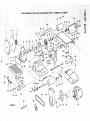
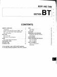
FIGURE 1
39
38
37
67
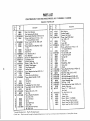
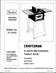
PARTSLiST
CRAFTSMAN
BELT AND DISC SANDER
FIGURE
Key
! PARTS
Part
No,
F,}
O1
MODEL NO. 113.225900
I
1
2
3
4
38834
68033
STD503103
30646
5
6
7
STD600803
68003
133656
8
9
10
1!
t2
13
14
15
16
17
18
19
20
21
22
68004
68069
STD580025
38812
STD523115
STD551131
68005
STD55103i
68068
37158
60434
STD523t10
47222
47190
STD502502
23
24
25
26
27
28
29
30
3509
68006
STD551210
STD511105
68070
STD551037
68007
STD510605
31
32
33
34
35
68008
47815
68009
68010
STD510803
Standard
1 Stock
item
Hardware
-- May
36
tDisc, 9 Inch Abrasive
Disc, Sanding (wtSet Screw)
*Screw, Socket Head Set, 5/16-18 x 51t6
tPutley (w/Set Screw) 2-1/2 dia. x 1/2,
"V" Groove 5/8 bore, Keyed
*Screw, Type 23, Pan No. 8-32 x 3/8
Cover, Housing
"Screw, Machine Flat Head No, 10-32
x t-3/4
Housing, Disc
Shaft, Drive
Key, Woodruff, No. 9
Key, Woodruff
"Screw, Hex Head 5/16-18 x t-1/2
* Lockwasher, 5/16
Bracket, Mounting
*Washer, 21/64 x 7/8 x t/8
i Bracket, Table Support
Ring, Retaining 5/8
Bearing, Ball
*Screw, Machine Hex Head 5/16-18 x 1
Backstop
Pulley, Drive (w/Set Screw}
"Screw, Socket Head Set, 1/4-20
x 5/16
Bearing Bali
Trap, Dust
*Lockwasher No. 10 Int. Tooth
*Screw Math. Pan Hd, 10-32 x 9/16
Table, Belt
*Washer, 3/8 x 3/4 x t/16
Nut, Cam
*Screw, Machine Pan Slotted
No. 6-32 x 7/!6
Cam, Left Hand
Spring
Cam, Right Hand
Guard, Idler
*Screw, Machine Pan Head
No. 8-32 x 3/8
I
Item
- May Be Purchased
be secured
through
the
LIST
Key
No.
Description
No.
8,. 113.225930
Part
38
39
47813
60254
60253
STD601105
4O
41
42
43
60255
60252
STD304410
62023
44
45
46
47
47622
STD571807
38538
38536
68015
47621
60096
47414
68017
STD512505
STD551125
100167
STD541250
STD523107
STD523122
68016
STD541025
STD522512
38738
9416187
37
48
49
5O
51
52
55
56
67
58
59
60
6t
62
63
64
65
66
67
Description
No,
t Belt, Sanding
Bracket, Support
Support,
Belt
Guard
"Screw, Type 23 Pan Head
No. 10-32 x 1/2
"S" Clip
Guard, Belt
lV-Beit, 1/2 x 4!"
tPulley, (w/Set Screw) 2" Oia. x 1/2
"V'" Groove 5/8 Bore
Shaft, Contro!
Pin, Roll 3/16 x 5/8
Ring, Retaining 5/8
Bearing, Ball
Base
Shaft, Idler
"Wrench Hex., 5/32
Pulley, Idler
Wrench
*Screw, Machine Pan Head I/4-20 x 1/2
* Lockwashero 1/4
*Bolt, Hex. Head, 1/2-13 x 4-1/2
*Nut, Hexo, 1/2-13
Bolt, High Strength, 5/16-18 x 3/4
Bolt, High Strength, 5/16_18 x 2-1/4
Support Assembly, Base
*Nut, Hex., 1/4-20
*Screw, Machine Hex. Head, 1/4-20 x!-1/4
Bracket, Table Lock
*Screw, Ty "T" 5/16-18 x 3/4
Hex. Head
*Pin, Roll 3/16 x 1-I/4
Table, Work
Hanger_ Cable
IMotor
(Model 113.225930)
Owner's Manual (Not lllustrated)
Bag of Loose Parts (Not Illustrated)
Bag of Loose Parts {Not Illustrated)
STD5718t2
68055
68036
68063
68067
68035
68064
Locally,
Hardware
Department
of most
Sears
or SimpsonsSears
Retait
Stores
or
Catatog
Order
Houses
epalr
parts
CRAFTSMAN=BELT
AND DISC SANDER
MODEL NO; 113.225900
& 113.225930
7
8
4
ON/OFF
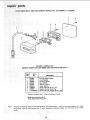
FIGURE 2 PARTS LIST
POWER OUTLET 60382 AND MOUNTING
BRACKET
I No.
z_
!
-
_t
60375
2
60378
3
60256
4
60374
5 60376
6
448007
7
68066
8
STD600803
*Standard
Hardware
o Does Not Include
Order Separately
NOTE:
Shipping
and handling
charges for standard
buying
these items by mail uneconomical.
Cord, Molded
Housing, Switch
Key, Switch
Switch, Locking
Cover; Switch
Screw, Pan Hd. No. 6 x 3/4
Bracket, Switch Mounting
*Screw, Pan Hd. Plastite No. 8 x 3/8
Item - May be Purchased
Key No. 3.
If Required.
hardware
To avoid
items [identified
by ") such as nuts. screws, washers, etc., make
shipping and handling
charges, you may obtain most of these
locally.
•.
i
i: \
Locally.
;
26
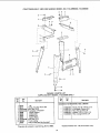
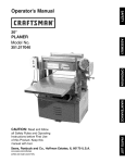
CRAFTSMAN
BELT AND DISC SANDER
MODEL NO. 113.225900
& 113.225930
5
1
/
2
4
SUPPLIED
Key
No.
irrrll
Part
No.
FIGURE 3 PARTS LIST
WITH MODEL 113.225930
Key
No,
Description
iii
i
-,,,
11111, 1111111
3
ONLY
Part
No.
Description
.i,
i
.,.NI,
HARDWARE FOR MOUNTING TOOL & MOTOR
1
2
3
4
5
6
7
8
9
10
-
62614
Leg
t Screw,TrussHd. t/4-20 x 5/8
60314
STD541025 t'Nut, Hex 1/4-20
STD551225 t* Lockwasher,
I/4 External
68060
Channel,Support
68059
Stiffener,Side
62615
Stiffener, End
68061
Support,Motor
STD541050 t'Nut, Hex 1/2-13
803835
1"Foot, Leveling
68062
? Bagof LooseParts(Not illustrated)
w
STD523125 t'Screw, Hex Hd. 5/16-78 x 2-1/2
STD551t31 ?*Lockwasher,External5/!6
STD541231 t'Nut, HexJam 5/!6 x 18
STD551031 t'Washer, 11/32 x 11/!6 x 1/16
STD532507 t'Bolt, Carriage5/16-18 x 3/4
*Standard HardwareItem - May be PurchasedLocally.
tTheseitemsall containedin Loose PartsBag.PartNo. 68062.
27
Sears
BE/.. T AND
DISC
SANDER
SERVICE
MODEL NO.
Now that you have purchased your Belt & Disc Sander should a
need ever exist for repair parts or service, simply contact any
Sears Service Center and most Sears, Roebuck and Co. stores.
Be sure to provide all pertinent facts when you call or visit.
113.225900
BELT AND DISC
SANDER ONLY
MODEL NO.
113.225930
The model number
on a plate attached
base.
of your
to your
Belt and Disc Sander will be found
sander at the,_right-hand side of the
BELT AND DISC
SANDER/WITH
LEGS AND MOTOR
HOW TO ORDER
REPAIR PARTS
WHEN ORDERING
REPAIR
FOLLOWING
INFORMATION:
Part
No.
by
SEARS,
68067
GIVE
PART
MODEL NUMBER
113.225900 OR
113.225930
NAME OF ITEM
Belt And Disc Sander
ROEBUCK
AND
Form
)
ALWAYS
PART NUMBER
All parts listed may be
and most Sears stores.
Ioca!_y, your order will
Repair Parts Distribution
Sold
PARTS,
No.
CO',
SP4574-3
THE
DESCRIPTION
ordered from any Sears Service Center
If the parts you need are not stocked
be electronically
transmitted to a Sears
Center for handling.
Chicago,
IL.
60684
Printed
U.S.A.
in U.S.A.
12/82