1
MDG30PCC
(30 Lb Single Pocket, Phase 7 Coin)
Installation Manual
WARNING: For your safety the information in
this manual must be followed to minimize the
risk of fire or explosion or to prevent property
damage, personal injury or death.
AVERTISSEMENT: Assurez-vous de bien
suivre les instructions données dans cette notice
pour réduire au minimum le risque dincendie
ou dexplosion ou pour éviter tout dommage
matériel, toute blessure ou la mort.
Do not store or use gasoline or other flammable
vapors and liquids in the vicinity of this or any
other appliance.
Ne pas entreposer ni utiliser dessence ni
dautres vapeurs ou liquides inflammables à
proximité de cet appareil ou de tout autre
appareil.
WHAT TO DO IF YOU SMELL GAS:
Do not try to light any appliance.
Do not touch any electrical switch; do not
use any phone in your building.
Clear the room, building or area of all
occupants.
Immediately call your gas supplier from a
neighbors phone. Follow the gas suppliers
instructions.
If you cannot reach your gas supplier, call
the fire department.
Installation and service must be performed by a
qualified installer, service agency or the gas
supplier.
QUE FAIRE SI VOUS SENTEZ UNE ODEUR
DE GAZ:
Ne pas tenter dallumer dappareils.
Ne touchez à aucun interrupteur. Ne pas
vous servir des téléphones se trouvant dans
le bâtiment.
Évacuez la pièce, le bâtiment ou la zone.
Appelez immédiatement votre fournisseur
de gaz depuis un voisin. Suivez les
instructions du fournisseur.
Si vous ne pouvez rejoindre le fournisseur
de gaz, appelez le service des incendies.
Linstallation et lentretien doivent être assurés par
un installateur ou un service dentretien qualifié
ou par le fournisseur de gaz.
RETAIN THESE INSTRUCTIONS IN A SAFE
PLACE FOR FUTURE REFERENCE
072303MGOLDSTEIN/tcosta
Part No. 113201
Retain This Manual In A Safe Place For Future Reference
Our products embody advanced concepts in engineering, design, and safety. If this product is properly maintained, it will
provide many years of safe, efficient, and trouble free operation.
ONLY qualified technicians should service this equipment.
OBSERVE ALL SAFETY PRECAUTIONS displayed on the equipment or specified in the installation manual included with
the dryer.
The following FOR YOUR SAFETY caution must be posted near the dryer in a prominent location.
FOR YOUR SAFETY
POUR VOTRE SÉCURITÉ
Do not store or use gasoline or
other flammable vapors and
liquids in the vicinity of this or
any other appliance.
Ne pas entreposer ni utiliser dessence
ni dautres vapeurs ou liquides
inflammables à proximité de cet
appareil ou de tout autre appareil.
We have tried to make this manual as complete as possible and hope you will find it useful. The manufacturer reserves the
right to make changes from time to time, without notice or obligation, in prices, specifications, colors, and material, and to
change or discontinue models. The illustrations included in this manual may not depict your particular dryer exactly.
Important
For your convenience, log the following information:
MDG30PCC
DATE OF PURCHASE ________________________________ MODEL NO. __________________________________________
DEALERS NAME __________________________________________________________________________________________
Serial Number(s)
________________________________________________________________________________________
________________________________________________________________________________________
________________________________________________________________________________________
For replacement parts, contact the dealer from which the dryer was purchased or contact:
MAYTAG CO.
403 West Fourth Street North
Newton, Iowa 50208
(641) 787-7000
IMPORTANT NOTE TO PURCHASER
Information must be obtained from your local gas supplier on the instructions
to be followed if the user smells gas. These instructions must be posted in a
prominent location near the dryer.
IMPORTANT
YOU MUST DISCONNECT AND LOCK OUT THE ELECTRIC SUPPLYAND THE GAS
SUPPLY OR THE STEAM SUPPLY BEFORE ANY COVERS OR GUARDS ARE
REMOVED FROM THE MACHINE TO ALLOW ACCESS FOR CLEANING,
ADJUSTING, INSTALLATION, OR TESTING OF ANY EQUIPMENT PER OSHA
(Occupational Safety and Health Administration) STANDARDS.
Caution: Label all wires prior to
disconnection when servicing controls. Wiring
errors can cause improper operation.
«Attention: Au moment de lentretien des
commandes, étiquetez tous les fils avant de
les débrancher. Des erreurs de câblage
peuvent entraîner un fonctionnement
inadéquat et dangereux.»
CAUTION
DRYERS SHOULD NEVER BE LEFT UNATTENDED WHILE IN OPERATION.
WARNING
CHILDREN SHOULD NOT BE ALLOWED TO PLAY ON OR NEAR THE DRYER(S).
CHILDREN SHOULD BE SUPERVISED IF NEAR DRYERS IN OPERATION.
FOR YOUR SAFETY
DO NOT DRY MOP HEADS IN THE DRYER.
DO NOT USE DRYER IN THE PRESENCE OF DRY CLEANING FUMES.
WARNING
UNDER NO CIRCUMSTANCES should the door switch or the heat circuit devices
ever be disabled.
WARNING
The dryer must never be operated with any of the back guards, outer tops, or service
panels removed. PERSONAL INJURY OR FIRE COULD RESULT.
WARNING
DRYER MUST NEVER BE OPERATED WITHOUT THE LINT FILTER/SCREEN IN
PLACE, EVEN IF AN EXTERNAL LINT COLLECTION SYSTEM IS USED.
IMPORTANT
PLEASE OBSERVE ALL SAFETY PRECAUTIONS displayed on the equipment and/or
specified in the installation manual included with the dryer.
Dryer must not be installed or stored in an area where it will be exposed to water or weather.
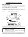
The wiring diagram for the dryer is located in the front electrical control box area.
IMPORTANT
Dryer must be installed in a location/environment, which the ambient temperature
remains between 40° F (4.44° C) and 130° F (54.44° C).
Table of Contents
SECTION I
SAFETY PRECAUTIONS ......................................................................................... 3
SECTION II
SPECIFICATIONS ..................................................................................................... 5
SECTION III
INSTALLATION PROCEDURES ........................................................................... 7
A.
B.
C.
D.
E.
F.
G.
H.
I.
J.
K.
Unpacking and Setting Up .......................................................................................................... 7
Location Requirements ............................................................................................................... 8
Dryer Enclosure Requirements .................................................................................................... 9
Fresh Air Supply Requirements ................................................................................................. 10
Exhaust Requirements ............................................................................................................... 11
Electrical Information ................................................................................................................ 17
Gas Information ........................................................................................................................ 20
Preparation For Operation and Start-Up ................................................................................... 24
Preoperational Tests ................................................................................................................. 25
Preoperational Instructions ........................................................................................................ 26
Shutdown Instructions ............................................................................................................... 27
SECTION V
SERVICE/PARTS INFORMATION ...................................................................... 28
A. Service ..................................................................................................................................... 28
B. Parts ........................................................................................................................................ 28
SECTION V
WARRANTY INFORMATION............................................................................... 29
A. Returning Warranty Cards ......................................................................................................... 29
B. Warranty .................................................................................................................................. 29
SECTION VI
ROUTINE MAINTENANCE .................................................................................. 30
A. Cleaning ................................................................................................................................... 30
B. Adjustments ............................................................................................................................. 31
C. Lubrication ............................................................................................................................... 31
SECTION VII
DATA LABEL INFORMATION ............................................................................. 32
SECTION VIII
PROCEDURE FOR FUNCTIONAL CHECK OF REPLACEMENT
COMPONENTS ........................................................................................................ 34
SECTION IX
MANUAL RESET BURNER HI-LIMIT INSTRUCTIONS ............................... 36
SECTION I
SAFETY PRECAUTIONS
WARNING: For your safety, the information in this manual must be followed to minimize the risk of
fire or explosion or to prevent property damage, personal injury, or loss of life.
WARNING: The dryer must never be operated with any of the back guards, outer tops, or
service panels removed. PERSONAL INJURY OR FIRE COULD RESULT.
1. DO NOT store or use gasoline or other flammable vapors and liquids in the vicinity of this or any other
appliance.
2. Purchaser or user should consult the local gas supplier for proper instructions to be followed in the event the
user smells gas. The instructions should be posted in a prominent location.
3. WHAT TO DO IF YOU SMELL GAS:
a. DO NOT try to light any appliance.
b. DO NOT touch any electrical switch.
c. DO NOT use any phone in your building.
d. Clear the room, building, or area of ALL occupants.
e. Immediately call your gas supplier from a neighbors phone. Follow the gas suppliers instructions.
f. If you cannot reach your gas supplier, call the fire department.
4. Installation and service must be performed by a qualified installer, service agency, or gas supplier.
5. Dryers must be exhausted to the outdoors.
6. Although Maytag produces a very versatile dryer, there are some articles that, due to fabric composition or
cleaning method, should not be dried in it.
WARNING: Dry only water washed fabrics. DO NOT dry articles spotted or washed in dry
cleaning solvents, a combustible detergent, or all purpose cleaner.
EXPLOSION COULD RESULT.
WARNING: DO NOT dry rags or articles coated or contaminated with gasoline, kerosene, oil, paint,
or wax.
EXPLOSION COULD RESULT.
WARNING: DO NOT dry mop heads. Contamination by wax or flammable solvents will create a
fire hazard.
3
WARNING: DO NOT use heat for drying articles that contain plastic, foam, sponge rubber, or
similarly textured rubber materials. Drying in a heated basket (tumbler) may damage
plastics or rubber and may be a fire hazard.
7. A program should be established for the inspection and cleaning of lint in the burner area, exhaust ductwork,
and area around the back of the dryer. The frequency of inspection and cleaning can best be determined
from experience at each location.
WARNING: The collection of lint in the burner area and exhaust ductwork can create a potential fire
hazard.
8. For personal safety, the dryer must be electrically grounded in accordance with local codes and/or the
National Electrical Code ANSI/NFPA NO. 70-LATEST EDITION or in Canada, the Canadian Electrical
Codes Parts 1 & 2 CSA C22.1-1990 or LATEST EDITION.
NOTE: Failure to electrically ground the dryer properly will VOID THE WARRANTY.
9. UNDER NO CIRCUMSTANCES should the door switch or the heat circuit devices ever be disabled.
WARNING: PERSONAL INJURY OR FIRE COULD RESULT should the door switch or the
heat circuit devices ever be disabled.
10. This dryer is not to be used in the presence of dry cleaning solvents or fumes.
11. Remove articles from the dryer as soon as the drying cycle has been completed.
WARNING: Articles left in the dryer after the drying and cooling cycles have been completed can
create a fire hazard.
12. READ AND FOLLOW ALL CAUTION AND DIRECTION LABELS ATTACHED TO THE
DRYER.
13. For safety, proper operation, and optimum performance, the dryer must not be operated with a load less
than sixty-six percent (66%) 19 lbs (8 kg) of its rated capacity.
WARNING: YOU MUST DISCONNECT AND LOCK OUT THE ELECTRIC SUPPLY
AND THE GAS SUPPLY BEFORE ANY COVERS OR GUARDS ARE
REMOVED FROM THE MACHINE TO ALLOW ACCESS FOR CLEANING,
ADJUSTING, INSTALLATION, OR TESTING OF ANY EQUIPMENT PER
OSHA (Occupational Safety and Health Administration) STANDARDS.
IMPORTANT: Dryer must be installed in a location/environment, which the ambient
temperature remains between 40º F (4.44º C) and 130º F (54.44º C).
4
SECTION II
SPECIFICATIONS
OEV
NJ
%$6.(7780%/(5',$0(7(5
´
FP
%$6.(7 780%/(5'(37+
´
FP
%$6.(7 780%/(5 02725
KS
N:
'22523(1,1* ',$0(7(5
´
FP
%$6.(7780%/(5 92/80(
FXIW
FXP
0$;,080&$3$&,7< '5<:(,*+7
'5<(563(5¶¶&217$,1(5
'5<(563(5¶¶758&.
GAS
92/7$*($9$,/$%/(
Y¡¡Z+]
$3352;:(,*+781&5$7('
OEV
NJ
$3352;:(,*+7&5$7('
OEV
NJ
%WXKU
NFDOKU
FIP
FPP
+($7,1387
$,5)/2:
,1/(73,3(&211(&7,21
´0137
Shaded areas are stated in metric equivalents
8/1/03
* Size of piping to dryer varies with installation conditions. Contact factory for assistance.
NOTE: Manufacturer reserves the right to make changes in specifications at any time without notice or
obligation.
5
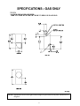
SPECIFICATIONS GAS ONLY
NOTE: Manufacturer reserves the right to make changes in specifications at any time without notice or
obligation.
6
SECTION III
INSTALLATION PROCEDURES
Installation should be performed by competent technicians in accordance with local and state codes. In the
absence of these codes, the installation must conform to applicable American National Standards: ANSI Z223.1LATEST EDITION (National Fuel Gas Code) or ANSI/NFPA NO. 70-LATEST EDITION (National Electrical
Code) or in Canada, the installation must conform to applicable Canadian Standards: CAN/CGA-B149.1-M91
(Natural Gas) or CAN/CGA-B149.2-M91 (Liquid Propane [L.P.] Gas) or LATEST EDITION (for General
Installation and Gas Plumbing) or Canadian Electrical Codes Parts 1 & 2 CSA C22.1-1990 or LATEST EDITION
(for Electrical Connections).
A. UNPACKING AND SETTING UP
Remove protective shipping material (i.e., plastic wrap and optional shipping box) from dryer.
IMPORTANT: Dryer must be transported and handled in an upright position at ALL times.
NOTE: The key for the top control door and bottom lint door is located in the information packaged
and shipped in the dryers basket (tumbler). This key should be made accessible because it
will be needed throughout various phases in the installation of the dryer.
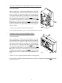
The dryer can be moved to its final location while still attached to the skid or with the skid removed. To unskid
the dryer, locate and remove the four (4) bolts securing the base of the dryer to the wooden skid. Two (2) are
at the rear base (remove the back panel for access), and two (2) are located in the bottom of the lint chamber.
To remove the two (2) bolts located in the lint chamber area, remove the lint door.
With the skid removed, to make it easier to slide the dryer into its final position, slightly lower ALL four (4)
leveling legs, so that the dryer will slide on the legs instead of the base frame.
The lint coops of ALL model dryers are supported during shipping by a bracket. REMOVE THIS BRACKET
BEFORE STARTING THE DRYER.
Leveling Dryer
The dryer is equipped with four (4) leveling legs, one (1) at each corner of the base. Two (2) are located at the
rear of the dryer base, and two (2) are located in the lint chamber (coop). To increase bearing life and improve
efficiency, the dryer should be tilted slightly to the rear.
7
B. LOCATION REQUIREMENTS
Before installing the dryer, be sure the location conforms to local codes and ordinances. In the absence of such
codes or ordinances the location must conform with the National Fuel Gas Code ANSI.Z223.1 LATEST
EDITION, or in Canada, the installation must conform to applicable Canadian Standards: CAN/CGA-B149.1M91 (Natural Gas) or CAN/CGA-B149.2-M91 (Liquid Propane [L.P.] Gas) or LATEST EDITION (for General
Installation and Gas Plumbing).
1. The dryer must be installed on a sound level floor capable of supporting its weight. Carpeting must be
removed from the floor area that the dryer is to rest on.
IMPORTANT: The dryer must be installed on noncombustible floors only.
2. The dryer must not be installed or stored in an area where it will be exposed to water or weather.
3. The dryer is for use in noncombustible locations.
4. Provisions for adequate air supply must be provided as noted in this manual (refer to Fresh Air Supply
Requirements in Section D).
5. Clearance provisions must be made from noncombustible construction as noted in this manual (refer to
Dryer Enclosure Requirements in Section C).
6. Provisions must be made for adequate clearances for servicing and for operation as noted in this manual
(refer to Dryer Enclosure Requirements in Section C).
7. Dryer must be exhausted to the outdoors as noted in this manual (refer to Exhaust Requirements in
Section E).
8. Dryer must be located in an area where correct exhaust venting can be achieved as noted in this manual
(refer to Exhaust Requirements in Section E).
IMPORTANT: Dryer should be located where a minimum amount of exhaust duct will be necessary.
9. The dryer must be installed with a proper exhaust duct connection to the outside.
10. The dryer must be installed with provisions for adequate combustion and make-up air supply.
CAUTION: This dryer produces combustible lint and must be exhausted to the outdoors. Every 6
months, inspect the exhaust ducting and remove any lint build up.
IMPORTANT: Dryer must be installed in a location/environment, which the ambient
temperature remains between 40º F (4.44º C) and 130º F (54.44º C).
8
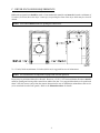
C. DRYER ENCLOSURE REQUIREMENTS
Bulkheads and partitions should be made of noncombustible materials and must be located a minimum of
12-inches (30.48 cm) above the dryers outer top; except along the front of the dryer which may be closed if
desired.
NOTE: Allowances must be made for opening the control door.
X = 12-inch (30.48 cm) minimum, 24-inches (60.96 cm) is suggested for ease of maintenance.
NOTE: Air considerations are important for proper and efficient operation.
Dryers may be positioned sidewall to sidewall. However, a 1/16 (1.5875 mm) minimum allowance must be
made for opening and closing of the control door and the lint door. It is suggested that the dryer be positioned
about 2 feet (0.61 meters) away from the nearest obstruction for ease of installation, maintenance, and service
(to be measured from the back guard). Refer to the illustration above for details.
9
D. FRESH AIR SUPPLY REQUIREMENTS
The air supply (make-up air) must be given careful consideration to assure proper performance of each dryer.
An unrestricted source of air is necessary for each dryer. As a general rule, an unrestricted air entrance from
the outdoors (atmosphere) of a minimum of 1-1/2 square feet (0.14 square meters) is required for each dryer. If
registers or louvers are installed over the openings, then the area must be increased. It is not necessary to have
a separate make-up air opening for each dryer. Common make-up air openings are acceptable. However, they
must be set up in such a manner that the make-up air is distributed equally to the dryers. The dryer must be
installed with provisions for adequate combustion and make-up air supply.
EXAMPLE: For a bank of eight (8) dryers, two (2) unrestricted openings measuring 2 feet by 3 feet
(6 square feet [0.61 meters by 0.91 meters] [0.55 square meters]) are acceptable.
IMPORTANT: Make-up air openings should not be located in an area directly near where exhaust
vents exit the building.
Allowances must be made for remote or constricting passageways or where dryers are located at excessive
altitudes or predominantly low pressure areas.
IMPORTANT: Make-up air must be provided from a source free of dry cleaning solvent fumes.
Make-up air that is contaminated by dry cleaning solvent fumes will result in
irreparable damage to the motors and other dryer components.
NOTE: Component failure due to dry cleaning solvent fumes will VOID THE WARRANTY.
10
E. EXHAUST REQUIREMENTS
Exhaust ductwork should be designed and installed by a qualified professional. Improperly sized ductwork will
create excessive back pressure which results in slow drying, increased use of energy, and shutdown of the
burner by the airflow (sail) switch, burner hi-limit, or lint chamber hi-limit protector thermostat. The dryer must
be installed with a proper exhaust duct connection to the outside.
When possible, it is suggested to provide a separate (single) exhaust duct for each dryer.
CAUTION: IMPROPERLY SIZED OR INSTALLED EXHAUST DUCTWORK CAN
CREATE A POTENTIAL FIRE HAZARD.
CAUTION: DRYER MUST BE EXHAUSTED TO THE OUTDOORS.
IMPORTANT: It is recommended that exhaust or booster fans not be used in the exhaust ductwork
system.
The exhaust ductwork should be laid out in such a way that the ductwork travels as directly as possible to the
outdoors with as few turns as possible. The shape of the ductwork is not critical as long as the minimum cross
section area is provided. Single or independent dryer venting is recommended.
It is suggested that the use of 90° turns be avoided; use 30° or 45° angles instead.
The ductwork should be smooth inside with no projections from sheet metal screws or other obstructions,
which will collect lint. When adding ducts, the ducts to be added should overlap the duct to which it is connected.
ALL ductwork joints must be taped to prevent moisture and lint from escaping into the building. Additionally,
inspection doors should be installed at strategic points in the exhaust ductwork for periodic inspection and
cleaning.
IMPORTANT: When connecting ductwork to the dryer exhaust duct, be sure that when screws are
used they DO NOT restrict the operation (both opening and closing) of the damper.
NOTE: When the exhaust ductwork passes through a wall, ceiling, or roof made of combustible
materials, the opening must be 2-inches (5.08 cm) larger than the duct (all the way around).
The duct must be centered within this opening.
To protect the outside end of the horizontal ductwork from the weather, a 90° elbow bent downward should be
installed where the exhaust exits the building. If the ductwork travels vertically up through the roof, it should be
protected from the weather by using a 180° turn to point the opening downward. In either case, allow at least
twice the diameter of the duct between the duct opening and the nearest obstruction (i.e., roof or ground level).
IMPORTANT: DO NOT use screens, louvers, or caps on the outside opening of the exhaust
ductwork.
IMPORTANT: Exhaust back pressure measured by a manometer at the dryer exhaust duct area must
be no less than 0 and must not exceed 0.3 inches (0.74 mb) of water column
(W.C.).
11
NOTE: As per the National Fuel Gas Code, Exhaust ducts for type 2 clothes dryers shall be
constructed of sheet metal or other noncombustible material. Such ducts shall be equivalent in
strength and corrosion resistance to ducts made of galvanized sheet steel not less than
0.0195-inches (26 gauge [0.05 mm]) thick.
SINGLE DRYER VENTING
IMPORTANT: For exhaust duct runs over 30 feet (9.14 meters) a minimum size of 10-inches
(25.4 cm) must be used.
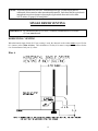
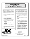
HORIZONTAL VENTING
When horizontal single 8-inch (20.32 cm) venting is used, the ductwork to the outlet cannot exceed 30 feet
(9.14 meters) refer to Illus. A below. This calculation of 30 feet (9.14 meters) compensates or allows for the
use of a maximum of only one (1) elbow.
Illus. A
12
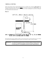
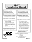
VERTICAL VENTING
When vertical single venting is used the minimum duct size is 10-inches (25.4 cm) refer to Illus. B below, the
ductwork from the dryer to the outside outlet cannot exceed 60 feet (18.3 meters) refer to Illus. B below. This
calculation compensates for the use of a maximum of three (3) elbows including the two (2) elbows creating the
180° (turned downward) outside outlet.
Illus. B
If the length of the duct run or quantity of elbows used exceeds the above noted specifications, the cross section
area of the ductwork must be increased in proportion to the number of elbows or duct run added.
IMPORTANT: For extended ductwork runs, the cross section area of the duct can only be increased
to an extent. For extended ductwork runs, a professional heating, ventilating, and
air-conditioning (HVAC) firm should be consulted for proper venting information.
13
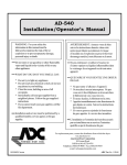
MULTIPLE DRYER (COMMON) VENTING
HORIZONTAL VENTING
If it is not feasible to provide separate exhaust ducts for each dryer, ducts for individual dryers may be channeled
into a common main duct. Each dryer is provided with a back draft damper. The individual ducts should enter
the bottom or side of the main duct at an angle not more than 45° in the direction of the airflow. No more than
four (4) dryers should be connected to one (1) main common duct run.
The main common duct may be any shape as long as the minimum cross-sectional area is provided. The main
duct should be tapered with the diameter increasing before each individual 8-inch (20.32 cm) duct is added
(refer to Illus. C below and Illus. D on the next page).
Illus. C
MULTIPLE DRYER VENTING (HORIZONTAL)
Horizontal venting must not exceed 20 feet (6.1 meters) this calculation compensates for the use of a
maximum of only one (1) elbow, which is the outside outlet protection.
NOTE: Distance between dryer single ducts being connected to the main common duct must be a
minimum of 31-3/8 (79.7 cm) dryer width.
Ductwork should be laid out in such a manner where allowances are made at rear area of the
dryer for removal of rear service panels or guards.
Illus. C shows the minimum cross section area for horizontal multiple dryer venting. These figures must be
increased in proportion if the main duct run from the last dryer to where it exhausts has numerous elbows or is
unusually long.
14
IMPORTANT: For extended ductwork runs, the cross section area of the duct can only be increased
to an extent. For extended ductwork runs, a professional heating, ventilating, and
air-conditioning (HVAC) firm should be consulted for proper venting information.
VERTICAL VENTING
Illus. D
MULTIPLE DRYER VENTING (VERTICAL)
The maximum length of venting from the last dryer to where it exhausts:
Vertical venting must not exceed 25 feet (7.62 meters) this calculation compensates for the use of a maximum
of three (3) elbows including the two (2) elbows creating the 180° (turned downward) outside outlet protection.
IMPORTANT: No more than four (4) dryers maximum should be connected to one (1) main
common duct with a vertical run.
NOTE: Distance between dryer single ducts being connected to the main common duct must be a
minimum of 31-3/8 (79.7 cm) dryer width.
Ductwork should be laid out in such a manner where allowances are made at rear area of the
dryer for removal of rear service panels or guards.
Illus. D shows the minimum cross section area for vertical multiple dryer venting. These figures must be
increased in proportion if the main duct run from the last dryer to where it exhausts has numerous elbows or is
unusually long.
IMPORTANT: For extended ductwork runs the cross section area of the duct can only be increased
to an extent. For extended ductwork runs a professional HVAC firm should be
consulted for proper venting information.
15
IMPORTANT VENTING REMINDERS
1. Ductwork size and installation should be done by a qualified professional.
2. The dryer must be exhausted to the outdoors.
3. Ductwork should be routed as short as possible to the outdoors with as few elbows as possible.
4. Avoid 90° turns, use 30° or 45° turns instead.
5. The size of the ductwork must be a minimum of 10-inches (25.4 cm) if vented vertically and 8-inches
(20.32 cm) if vented horizontally.
6. The inside of the ductwork should be as smooth as possible with no projections from sheet metal screws.
Ducts added should overlap the duct to which it is to be connected.
7. ALL ducts should be taped to prevent moisture and lint from escaping into the building.
8. Inspection or clean out doors should be installed throughout strategic points in the ductwork for periodic
inspection and cleaning.
9. Whenever the duct passes through combustible materials, the opening must be 2-inches (5.08 cm) larger
than the duct (all the way around). The duct must be centered within this opening.
10. The outside of the ductwork must be protected from the weather. A 90° elbow must be used for horizontal
run and when vertically through a roof by using a 180° turn to point the opening downward. The distance
between the exhaust duct and the nearest obstruction (i.e., roof or ground) must be twice the diameter of
the duct.
11. DO NOT use screens, louvers, or caps on the outside opening of the exhaust ductwork.
12. Exhaust back pressure measured by a manometer at the dryer exhaust duct area must be no less than 0
and must not exceed 0.3 inches (0.74 mb) of water column (W.C.).
13. WARNING DRYER MUST NEVER BE OPERATED WITHOUT THE LINT FILTER AND
SCREEN IN PLACE, EVEN IF AN EXTERNAL LINT COLLECTION SYSTEM IS USED.
14. Exhaust ductwork outlets should not be located in an area directly where the make-up air openings are
located.
IMPORTANT: It is recommended that exhaust or booster fans not be used in the exhaust ductwork
system.
16
F. ELECTRICAL INFORMATION
1. Electrical Requirements
ALL electrical connections must be made by a properly licensed and competent electrician. This
is to ensure that the electrical installation is adequate and conforms to local and state regulations or codes.
In the absence of such codes, ALL electrical connections, materials, and workmanship must conform to
the applicable requirements of the National Electrical Code ANSI/NFPA NO. 70-LATEST EDITION or in
Canada, the Canadian Electrical Codes Parts 1 & 2 CSA C22.1-1990 or LATEST EDITION.
IMPORTANT: Failure to comply with these codes or ordinances, and/or the requirements stipulated
in this manual can result in personal injury or component failure.
NOTE: Component failure due to improper installation will VOID THE WARRANTY.
Each dryer should be connected to an independently protected branch circuit. The dryer must be connected
with copper wire only. DO NOT use aluminum wire, which could cause a fire hazard. The copper
conductor wire/cable must be of proper ampacity and insulation in accordance with electric codes for
making ALL service connections.
NOTE: The use of aluminum wire will VOID THE WARRANTY.
IMPORTANT: A separate protected circuit must be provided to each dryer.
NOTE: An individual ground circuit must be provided to each dryer, do not daisy chain.
IMPORTANT: The dryer must be connected to the electric supply shown on the data label.
IMPORTANT: The wire size must be properly sized to handle the related current.
NOTE: Component failure due to improper voltage application will VOID THE WARRANTY.
NOTE: Manufacturer reserves the right to make changes in specifications at any time without notice or
obligation.
17
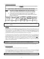
2. Electrical Service Specifications
*$6
(/(&75,&$/6(59,&(63(&,),&$7,2163(5'5<(5
127(6$:KHQIXVHVDUHXVHGWKH\PXVWEHGXDOHOHPHQWWLPHGHOD\FXUUHQWOLPLWLQJ
FODVV5.RU5.21/<&DOFXODWHGHWHUPLQHFRUUHFWIXVHYDOXHE\DSSO\LQJ
HLWKHUORFDODQGRU1DWLRQDO(OFWULFDO&RGHVWROLVWHGDSSOLDQFHDPSGUDZGDWD
% &LUFXLWEUHDNHUVDUHWKHUPDOPDJQHWLFLQGXVWULDOPRWRUFXUYHW\SH21/<)RU
RWKHUVFDOFXODWHYHULI\FRUUHFWEUHDNHUVL]HDFFRUGLQJWRDSSOLDQFHDPSGUDZUDWLQJ
DQGW\SHRIEUHDNHUXVHG
6(59,&(
92/7$*(
3+$6(
¡
:,5(
6(59,&(
$3352;
$03'5$:
)86,1*
+]
+]
'XDO(OHPHQW
7LPH'HOD\
²
&,5&8,7
%5($.(5
1/15/04
IMPORTANT: Figures shown are for non-reversing models only. For reversing models contact the
factory.
3. Grounding
A ground (earth) connection must be provided and installed in accordance with state and local codes. In
the absence of these codes, grounding must conform to applicable requirements of the National Electrical
Code ANSI/NFPA NO. 70-LATEST EDITION, or in Canada, the installation must conform to applicable
Canada Standards: Canadian Electrical Codes Parts 1 & 2 CSA C22.1-1990 or LATEST EDITION. The
ground connection may be to a proven earth ground at the location service panel.
For added personal safety, when possible, it is suggested that a separate ground wire (no. 18 minimum) be
connected from the ground connection of the dryer to a grounded cold water pipe. DO NOT ground to a
gas pipe or hot water pipe. The grounded cold water pipe must have metal-to-metal connection ALL the
way to the electrical ground. If there are any nonmetallic interruptions, such as, a meter, pump, plastic,
rubber, or other insulating connectors, they must be jumped out with no. 4 copper wire and securely
clamped to bare metal at both ends.
IMPORTANT: For personal safety and proper operation, the dryer must be grounded.
Provisions are made for ground connection in each dryer at the electrical service connection area.
4. Electrical Connections
A wiring diagram is located inside the control box for connection data.
If local codes permit, power to the dryer can be made by the use of a flexible U.L. listed power cord/pigtail
(wire size must conform to rating of dryer), or the dryer can be hard wired directly to the service breaker
panel. In both cases, a strain relief must be installed where the wiring enters the dryer.
IMPORTANT: A separate protected circuit must be provided to each dryer.
18
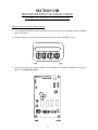
Single-Phase (1ø) Wiring Connections/Hookup
The electrical input connections on ALL single-phase (1ø) gas dryers are made into the rear service box
located at the upper left area of the dryer.
6LQJOH3KDVH(OHFWULFDO/HDG&RQQHFWLRQV
%ODFN
3RVLWLYH
:KLWHRU5HG
1HXWUDO
RU/
*UHHQ
*URXQG
FOR 110V APPLICATIONS
A ground lug is provided in the rear electrical box to connect your service ground.
19
G. GAS INFORMATION
It is your responsibility to have ALL plumbing connections made by a qualified professional to assure that the gas
plumbing installation is adequate and conforms to local and state regulations or codes. In the absence of such
codes, ALL plumbing connections, materials, and workmanship must conform to the applicable requirements of
the National Fuel Gas Code ANSI Z223.1-LATEST EDITION, or in Canada, the Canadian Installation Codes
CAN/CGA-B149.1-M91 (Natural Gas) or CAN/CGA-B149.2-M91 (Liquid Propane [L.P.] Gas) or LATEST
EDITION.
IMPORTANT: Failure to comply with codes or ordinances, and/or requirements in this manual, can
result in personal injury and improper operation of the dryer.
The dryer and its individual shutoff valves must be disconnected from the gas supply piping system during any
pressure testing of that system at test pressures in excess of 1/2 psig (3.5 kPa). The dryer must be isolated
from the gas supply piping system by closing its individual manual shutoff valve during any pressure test of the
gas supply system at test pressures equal to or less than 1/2 psig (3.5 kPa).
IMPORTANT: Failure to isolate or disconnect the dryer from supply as noted can cause irreparable
damage to the gas valve, which will VOID THE WARRANTY.
WARNING: FIRE OR EXPLOSION COULD RESULT due to failure of isolating or
disconnecting the gas supply as noted.
1. Gas Supply
The gas dryer installation must meet the American National Standard...National Fuel Gas Code ANSI
Z223.1-LATEST EDITION, or in Canada, the Canadian Installation Codes CAN/CGA-B149.1 M91 (Natural
Gas) or CAN/CGA-B149.2-M91 (L.P. Gas) or LATEST EDITION, as well as local codes and ordinances
and must be done by a qualified professional.
NOTE: Undersized gas piping will result in ignition problems, slow drying, increased use of energy, and
can create a safety hazard.
The dryer must be connected to the type of heat or gas indicated on the dryer data label. If this information
does not agree with the type of gas available, DO NOT operate the dryer. Contact the dealer who sold
the dryer or contact the Maytag Co.
IMPORTANT: Any burner changes or conversions must be made by a qualified professional.
The input ratings shown on the dryer data label are for elevations up to 2,000 feet (609.6 meters), unless
elevation requirements of over 2,000 feet (609.6 meters) were specified at the time the dryer order was
placed with the factory. The adjustment or conversion of dryers in the field for elevations over 2,000 feet
(609.6 meters) is made by changing each burner orifice. If this conversion is necessary, contact the dealer
who sold the dryer or contact the Maytag Co.
20
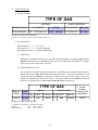
2. Technical Gas Data
a. Gas Specifications
7<3(2)*$6
1$785$/
LQFKHV:&
PE
LQFKHV:&
PE
LQFKHV:&
PE
LQFKHV:&
PE
0DQLIROG3UHVVXUH
,Q/LQH3UHVVXUH
/,48,'3523$1(
Shaded areas are stated in metric equivalents
* Measured at outlet side of gas valve pressure tap when gas valve is on.
b. Gas Connections
Inlet connection ---------- 1/2 N.P.T.
Inlet supply size ---------- 1/2 dia. (minimum)
Btu/hr input (per dryer) - 90,000 (22,680 kcal/hr)
1) Natural Gas
Regulation is controlled by the dryers gas valves internal regulator. Incoming supply pressure
must be consistent between a minimum of 6.0 inches (14.92 mb) and a maximum of 12.0 inches
(29.9 mb) of water column (W.C.) pressure.
2) Liquid Propane (L.P.) Gas
Dryers made for use with L.P. gas have the gas valves internal pressure regulator blocked open so
that the gas pressure must be regulated upstream of the dryer. The pressure measured at each
gas valve pressure tap must be a consistent 10.5 inches (26.1 mb) of water column. There is no
regulator or regulation provided in an L.P. dryer. The water column pressure must be regulated at
the source (L.P. tank) or an external regulator must be added to each dryer.
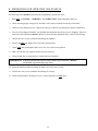
7<3(2)*$6
%WXKRXU
5DWLQJ
NFDOKU
5DWLQJ 4W\
'06
3DUW1R
4W\
'06
3DUW1R
/LTXLG
3URSDQH
&RQYHUVLRQ.LW
3DUW1XPEHU
1DWXUDO
/LTXLG3URSDQH
Shaded areas are stated in metric equivalents
* Drill Measurement Size (D.M.S.) equivalents are as follows:
Natural Gas ............................... #30 =
Liquid Propane Gas ................... #46 =
0.1285 (3.2639 mm).
0.0810 (2.06 mm).
21
3. Piping Connections
ALL components/materials must conform to National Fuel Gas Code Specifications ANSI Z223.1-LATEST
EDITION, or in Canada, CAN/CGA-B149.1-M91 (Natural Gas) or CAN/CGA-B149.2-M91 (Liquid
Propane [L.P.] Gas) or LATEST EDITION (for General Installation and Gas Plumbing), as well as local
codes and ordinances and must be done by a qualified professional. It is important that gas pressure
regulators meet applicable pressure requirements, and that gas meters be rated for the total amount of
ALL the appliance Btus being supplied.
The dryer is provided with a 1/2 N.P.T. inlet pipe connection located in the upper rear area of the dryer.
The minimum pipe size (supply line) to the dryer is 1/2 dia. For ease in servicing, the gas supply line of
each dryer must have its own shutoff valve.
IMPORTANT: The gas supply line to each dryer must be a minimum of 1/2. DO NOT REDUCE
THIS PIPE SIZE REQUIREMENT.
The size of the main gas supply line (header) will vary depending on the distance this line travels from the
gas meter or, in the case of L.P. gas, the supply tank, other gas-operated appliances on the same line, etc.
Specific information regarding supply line size should be determined by the gas supplier.
NOTE: Undersized gas supply piping can create a low or inconsistent pressure, which will result in
erratic operation of the burner ignition system.
22
Consistent gas pressure is essential at ALL gas connections. It is recommended that a 3/4-inch (19.05
mm) pipe gas loop be installed in the supply line servicing a bank of dryers. An in-line pressure regulator
must be installed in the gas supply line (header) if the (natural) gas pressure exceeds 12.0 inches (29.9
mb) of water column (W.C.) pressure. Refer to the illustrations on the previous page.
NOTE: A water column test pressure of 3.5 inches (8.7 mb) for natural gas and 10.5 inches (26.1 mb)
for liquid propane (L.P.) dryers is required at the gas valve pressure tap of each dryer for
proper and safe operation.
A 1/8 N.P.T. plugged tap, accessible for a test gauge connection, must be installed in the main gas supply
line immediately upstream of each dryer.
IMPORTANT: Pipe joint compounds that resist the action of natural gas and L.P. gas must be used.
IMPORTANT: Test ALL connections for leaks by brushing on a soapy water solution (liquid
detergent works well).
WARNING: NEVER TEST FOR LEAKS WITH A FLAME!!!
IMPORTANT: The dryer and its individual shutoff valve must be disconnected from the gas supply
piping system during any pressure testing of that system at test pressures in excess of
1/2 psig (3.5 kPa).
NOTE: The dryer must be isolated from the gas supply piping system by closing its individual manual
shutoff valve during any pressure test of the gas supply system at test pressures equal to or less
than 1/2 psig (3.5 kPa).
23
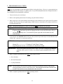
H. PREPARATION FOR OPERATION AND START-UP
The following items should be checked before attempting to operate the dryer:
1. Read ALL CAUTION, WARNING, and DIRECTION labels attached to the dryer.
2. Check incoming supply voltage to be sure that it is the same as indicated on the dryer data label.
3. Check to assure that the dryer is connected to the type of heat or gas indicated on the dryer data label.
4. The sail switch damper assembly was installed and adjusted at the factory prior to shipping. However,
each sail switch adjustment must be checked to assure that this important safety control is functioning.
5. Check bolts, nuts, screws, terminals, and fittings for tightness.
6. Be sure that ALL gas shutoff valves are in the open position.
7. Check ALL back guard panels and service box covers have been replaced.
8. Make sure the lint coop support bracket has been removed.
9. Check the lint door to assure that it is closed and secured in place.
IMPORTANT: If during installation the lint door safety chain was disconnected, it must be
reconnected or personal injury may result.
10. Rotate the basket (tumbler and drum) by hand to be sure it moves freely.
11. Check bolts, nuts, screws, terminals, and fittings for security.
12. Check basket (tumbler) bearing setscrews to ensure that they are ALL tight.
24
I. PREOPERATIONAL TESTS
ALL dryers are thoroughly tested and inspected before leaving the factory. However, a preoperational test
should be performed before the dryer is publicly used. It is possible that adjustments have changed in transit or
due to marginal location (installation) conditions.
1. Turn on electric power to the dryer.
2. Refer to the Operating Instructions for starting your particular model dryer.
3. When a gas dryer is first started (during initial start-up), it has a tendency not to ignite on the first ignition
attempt. This is because the gas supply piping is filled with air, so it may take a few minutes for the air to
be purged from the lines.
NOTE: During the purging period, check to be sure that ALL gas shutoff valves are open.
NOTE: Dryers are equipped with a Direct Spark Ignition (DSI) system, which has internal diagnostics.
If ignition is not established after the first attempt, the heat circuit in the DSI module will lock
out until it is manually reset. To reset the DSI system, open and close the main door and
restart the dryer.
A gas pressure test should be taken at the gas valve pressure tap of each dryer to assure that the water
column (W.C.) pressure is correct and consistent.
NOTE: Water column pressure requirements (measured at the pressure tap of the gas valve body):
Natural Gas -----------------3.5 Inches (8.7 mb) Water Column.
Liquid Propane (L.P.) Gas ---10.5 Inches (26.1 mb) Water Column.
IMPORTANT: There is no regulator provided in an L.P. dryer. The water column pressure must be
regulated at the source (L.P. tank), or an external regulator must be added to each
dryer.
4. Make a complete operational check of ALL safety related circuits:
a. Door Switches
b. Hi-Limit Thermostats
c. Cycling Thermostat
NOTE: The sail switch can be checked for proper operation by opening the lint door while heating
circuit (gas burner or electric oven) is active (on). The heating unit should shut off within a few
seconds. If not, make necessary adjustments to the sail switch.
5. Make a complete operational check of ALL operating controls.
25
NOTE: If computer program changes are required, refer to the computer programming section of the
manual supplied with the dryer.
6. The dryer should be operated through one (1) complete cycle to assure that no further adjustments are
necessary and that ALL components are functioning properly.
BASKET (TUMBLER) COATING
The basket (tumbler) is treated with a protective coating. We suggest dampening old garments or cloth material
with a solution of water and nonflammable mild detergent and tumbling them in the basket (tumbler) to remove
this coating.
7. Check the electric service phase sequence (3-phase [3ø] models only). While the dryer is operating, check
to see if the blower wheel (impellor/fan) is rotating in the proper direction. Looking from the front, the
blower wheel (impellor/fan) should spin in the clockwise (CW) direction. If it is, the phasing is correct. If
the phasing is incorrect, reverse two (2) of the three (3) leads at connections L1, L2, and L3 of the power
supply to the dryer.
IMPORTANT: If the blower wheel (impellor/fan) is rotating in the wrong direction, it will drastically
reduce drying efficiency and it can also cause premature component failure.
J. PREOPERATIONAL INSTRUCTIONS
COIN MODELS
Microprocessor Controller (computer)
1. When the microprocessor controller (computer) is in the ready state, the liquid crystal display (L.C.D.)
screen will display Ready, Insert $XX.XX (amount) to Start.
2. Insert coin(s). Once the correct Amount To Start has been inserted, the L.C.D. will display Select
Temperature.
3. Select temperature by pressing HI, MED, or LO. The cycle will start and the L.C.D. will display the
Dry Cycle selected and the remaining time.
4. The dryer will continue through the drying and cooling cycles, until the vended time has expired.
NOTE: To stop dryer, open main door or pressing the pause key. Continuation of the cycle will
resume only after the door has been closed and any of the three (3) temperature selection is
pressed.
5. Upon completion of drying and cooling cycles, the tone (buzzer) will sound and the dryer will go into the
Anti-Wrinkle mode for 99 minutes, or until the main door has been opened.
IMPORTANT: For more detailed information regarding the microprocessor controller (computer) on
your dryer, refer to the microprocessor users manual included with the dryer.
26
K. SHUTDOWN INSTRUCTIONS
If the dryer is to be shutdown (taken out of service) for a period of time, the following must be performed:
1. Discontinue power to the dryer either at the external disconnect switch or the circuit breaker.
2. Discontinue the heat supply:
Discontinue the gas supply.
a. SHUT OFF external gas supply shutoff valve.
b. SHUT OFF internal gas supply shutoff valve located in the gas valve burner area.
27
SECTION IV
SERVICE/PARTS INFORMATION
A. SERVICE
Service must be performed by a qualified trained technician, service agency, or gas supplier. If service is
required, contact the dealer from whom the Maytag equipment was purchased. If the dealer cannot be
contacted or is unknown, contact the Maytag Co. for a dealer in your area.
NOTE: When contacting the Maytag Co., be sure to give them the correct model number and
serial number so that your inquiry is handled in an expeditious manner.
B. PARTS
Replacement parts should be purchased from the dealer from whom the Maytag equipment was purchased. If
the dealer cannot be contacted or is unknown, contact the Maytag Co. for a dealer in your area.
NOTE: When ordering replacement parts from the Maytag dealer or the Maytag Co. be sure to give
them the correct model number and serial number so that your parts order can be
processed in an expeditious manner.
28
SECTION V
WARRANTY INFORMATION
A. RETURNING WARRANTY CARDS
Before any dryer leaves the manufacturers test area, a warranty card is placed on the back side of the main
door glass. These warranty cards are intended to serve the customer where we record the individual installation
date and warranty information to better serve you should you file a warranty claim.
IMPORTANT: A separate warranty card must be completed and returned for each individual dryer.
NOTE: Be sure to include the installation date when returning the warranty card(s).
B. WARRANTY
For a copy of the manufacturers commercial warranty covering your particular dryer(s), contact the Maytag
dealer from whom you purchased the equipment and request a dryer warranty form. If the dealer cannot be
contacted or is unknown, warranty information can be obtained from the Maytag Co.
NOTE: Whenever contacting the Maytag Co. for warranty information, be sure to have the dryers
model number and serial number available so that your inquiry can be handled in an
expeditious manner.
29
SECTION VI
ROUTINE MAINTENANCE
A. CLEANING
A program and/or schedule should be established for periodic inspection, cleaning, and removal of lint from
various areas of the dryer, as well as throughout the ductwork system. The frequency of cleaning can best be
determined from experience at each location. Maximum operating efficiency is dependent upon proper air
circulation. The accumulation of lint can restrict this airflow. If the guidelines in this section are met, a
Maytag dryer will provide many years of efficient, trouble free, and most importantly, safe operation.
WARNING: LINT FROM MOST FABRICS IS HIGHLY COMBUSTIBLE. THE
ACCUMULATION OF LINT CAN CREATE A POTENTIAL FIRE HAZARD.
WARNING: KEEP DRYER AREA CLEAR AND FREE FROM COMBUSTIBLE
MATERIALS, GASOLINE, AND OTHER FLAMMABLE VAPORS OR
LIQUIDS.
NOTE: Suggested time intervals shown are for average usage, which is considered six (6) to eight (8)
operational (running) hours per day.
IMPORTANT: Dryer produces combustible lint and must be exhausted to the outdoors. Every 6
months, inspect the exhaust ducting and remove any lint build up.
SUGGESTED CLEANING SCHEDULE
EVERY THIRD OR FOURTH LOAD
Clean the lint screen every third or fourth load. A clogged lint screen will cause poor dryer performance. The
lint screen is located behind the lint door in the base of the dryer. Open the lint door, brush the lint off the lint
screen, and remove the lint. Inspect lint screen and replace if torn.
NOTE: The frequency of cleaning the lint screen can best be determined from experience at each
location.
WEEKLY
Clean lint accumulation from lint chamber, thermostat, and microprocessor temperature sensor (sensor bracket)
area.
WARNING: TO AVOID THE HAZARD OF ELECTRICAL SHOCK, DISCONTINUE
ELECTRICAL SUPPLY TO THE DRYER.
30
90 DAYS
Inspect and remove lint accumulation in customer furnished exhaust ductwork system from dryers internal
exhaust ducting.
WARNING: THE ACCUMULATION OF LINT IN THE EXHAUST DUCTWORK CAN
CREATE A POTENTIAL FIRE HAZARD.
WARNING: DO NOT OBSTRUCT THE FLOW OF COMBUSTION AND VENTILATION
AIR.
WARNING: INSPECT AND REMOVE ANY LINT ACCUMULATION, WHICH CAN CAUSE
THE BACK DRAFT DAMPER TO BIND OR STICK.
NOTE: A back draft damper that is sticking partially closed can result in slow drying and shutdown of
heat circuit safety switches or thermostats.
NOTE: When cleaning the dryer cabinets, avoid using harsh abrasives. A product intended for the
cleaning of appliances is recommended.
B. ADJUSTMENTS
7 DAYS AFTER INSTALLATION AND EVERY 6 MONTHS THEREAFTER
Inspect bolts, nuts, screws, setscrews, grounding connections, and nonpermanent gas connections (unions, shutoff
valves, and orifices). Motor and drive belts should be examined. Cracked or seriously frayed belts should be
replaced. Tighten loose V-belts when necessary. Complete operational check of controls and valves. Complete
operational check of ALL safety devices (door switches, lint drawer switch, sail switch, burner, and hi-limit
thermostats).
C. LUBRICATION
The motor bearings, idler bearings and under normal or most conditions the basket (tumbler) bearings are
permanently lubricated. It is physically possible to relubricate the basket (tumbler) bearings if you choose to do
so even though this practice is not necessary. Use Shell Alvania #2 grease or its equivalent. The basket
(tumbler) bearings used in the dryer DO NOT have a grease fitting. Provisions are made in the bearing housing
for the addition of a grease fitting which can be obtained elsewhere, or from the manufacturer by ordering kit
P/N 882159 (which includes two [2] fittings).
31
SECTION VII
DATA LABEL INFORMATION
When contacting the Maytag dealer, certain information is required to insure proper service/parts information.
This information is on the data label, which is located on the upper left side panel area behind the top control
(access) door. When contacting the Maytag Co., please have the model number and serial number available.
32
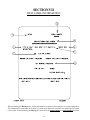
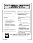
THE DATA LABEL
1. MODEL NUMBER
The model number is an Maytag Co. number, which describes the size of the dryer
and the type of heat (gas, electric, or steam).
2. SERIAL NUMBER
The serial number allows Maytag to gather information on your particular dryer.
3. MANUFACTURING CODE NUMBER
The manufacturing code number is a number issued by Maytag, which describes
ALL possible options on your particular model.
4. TYPE OF HEAT
This describes the type of heat for your particular dryer: gas (either natural gas or
liquid propane [L.P.] gas), electric, or steam.
5. HEAT INPUT (for GAS DRYERS)
This describes the heat input in British Thermal Units per Hour (Btu/hr).
6. ORIFICE SIZE (for GAS DRYERS)
Gives the number drill size used.
7. ELECTRIC SERVICE
This describes the electric service for your particular model.
8. GAS MANIFOLD PRESSURE (for GAS DRYERS)
This describes the manifold pressure taken at the gas valve tap.
33
SECTION VIII
PROCEDURE FOR FUNCTIONAL CHECK
OF REPLACEMENT COMPONENTS
1. Microprocessor Controller (Computer) Board
a. Upon completing installation of the replacement microprocessor controller (computer) board, reestablish
power to the dryer.
b. Start the drying cycle by pressing any temperature selection keys (HI, MED, or LO).
c. Verify that the applicable indicator lights on the microprocessor controller (computer) board are lit.
(Refer to the illustration below.)
34
2. For Models with Johnson Direct Spark Ignition (DSI) Controller (G760)
Theory of Operation:
Start the drying cycle. When the gas burner ignites within the
chosen trial for ignition time (6-seconds), the flame sensor detects
gas burner flame and signals the DSI module to keep the gas
valve open as long as there is a call for heat. The DSI module
will LOCK OUT if the gas burner flame is not sensed at the
end of the trial for ignition period. The trial for ignition period will
be repeated for a total of three (3) retries/trials (the initial try and
two [2] more retries/trials). If the flame is not sensed at the end
of the third retry/trial (inter-purge period of 30-seconds) the DSI
module will LOCK OUT (light emitting diode [L.E.D.] diagnostic
indicator flashes).
A steady L.E.D. indicator indicates normal operation.
No L.E.D. indicator indicates a power or an internal failure has occurred.
3. For Models with Fenwal Controls DSI Module (128937)
Theory of Operation:
Start the drying cycle. When the gas burner ignites within the
chosen trial for ignition time (8-seconds), the flame sensor detects
gas burner flame and signals the DSI module to keep the gas
valve open as long as there is a call for heat. The DSI module
will LOCK OUT if the gas burner flame is not sensed at the
end of the trial for ignition period. The trial for ignition period will
be repeated for a total of three (3) retries/trials (the initial try and
two [2] more retries/trials). If the flame is not sensed at the end
of the third retry/trial (inter-purge period of 30-seconds), the DSI
module will LOCK OUT (a red L.E.D. diagnostic indicator will
flash).
An unlit red L.E.D. diagnostic indicator indicates normal operation.
A lit green L.E.D. diagnostic indicator indicates dryer controller is calling for heat and that ALL interlocks
have been satisfied.
35
SECTION IX
MANUAL RESET BURNER HI-LIMIT INSTRUCTIONS
A. PHASE 7
This dryer was manufactured with a manual reset burner hi-limit thermostat, which is monitored by the Phase 7
computer. If the burner hi-limit is open prior to the start of the drying cycle, the dryer will start momentarily and
then shut down, the Phase 7 computer will display BURNER HIGH LIMIT FAULT with an audio indication.
If the burner hi-limit opens during a drying cycle, the Phase 7 computer will also display the same error code
described above, along with an audio indication. If the drum temperature is above 100° F (38° C), the dryer will
continue to run with no heat for 3 minutes or until the drum temperature has dropped below 100° F (38° C). The
clear/stop button on the Phase 7 keyboard (touch pad) must be pressed to clear the error condition. The open
burner hi-limit must be reset manually prior to the start of the next cycle.
B. DUAL TIMER
This dryer was manufactured with a manual reset burner hi-limit thermostat. If the burner hi-limit is open prior
to the start of the drying cycle, or during the cycle, the dryer will not recognize the open state of the burner
hi-limit and will start or continue through the drying cycle with no heat. Manual reset hi-limit must be reset
manually.
This hi-temperature condition may be caused due to a restricted exhaust, poor airflow, or improper burner
operation.
The location of the burner hi-limit is on the right side of the burner box, looking at the burner from the back of the
dryer.
WARNING: Discontinue power to dryer before attempting to reset hi-limit.
36
Part No. 113201
3 - 1/15/04 - 150