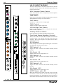
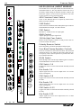
1
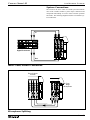
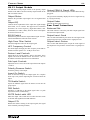
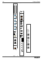
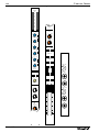
C E N T U RY S E R I E S
LM
O WNER ' S M ANUAL
Congratulations on your purchase of a Century Series console. All of us at Crest Audio in Paramus, New
Jersey, USA, support your decision, knowing your console contains the finest combination of design and
manufacture in the industry.
While your new Century Series console is one of the most feature-packed available, great effort has been
put into making it simple to operate.
This manual explains the functions of your new console, how they operate and how they relate to each
other. If properly cared for, your new console will provide you with trouble-free, sonically accurate mixing
clear into the next Century and beyond.
Please keep the following contact information on hand:
Crest Audio Customer Service Dept.
100 Eisenhower Drive
Paramus NJ 07652 USA
TEL 201.909.8700 FAX 201.909.8744
http://www.crestaudio.com
Crest Audio Inc.
100 Eisenhower Dr., Paramus NJ 07652 USA
TEL: 201.909.8700 FAX: 201.909.8744
http://www.crestaudio.com
Printed in USA
TABLE
OF
CONTENTS
LM Feature Overview
2
LM System Connections
3
A brief description of the LM design, features and functions.
Contains diagrams illustrating conventional system connections.
LM Wiring Conventions
5
Contains diagrams indicating how connectors for Crest consoles are wired.
LM Power Supply
6
A description of the rack-mountable Century Series consoles power supply.
LM Power Connections
7
A description of Crest console power connections.
LM Console Cooling
7
A brief description of the dual-fan cooling setup.
LM LM-12 Input Module
8
Profiles the LM-12 input module. The module is illustrated and described.
LM LM-20 (LM-8+4) Input Module
10
Profiles the LM-20 (LM-8+4) input module. The module is illustrated and described.
LM LM-12 Output Module
13
Profiles the LM-12 ouput module. The module is illustrated and described.
LM LM 8+4 Output Module
15
Profiles the LM-8+4 output module. The module is illustrated and described.
LM LM-20 Output Module
17
Profiles the LM-20 ouput module. The module is illustrated and described.
LM Master Module A
19
Profiles the LM A-Master module. The module is illustrated and described.
LM Master Module B
21
Profiles the LM B-Master module. The module is illustrated and described.
LM Technical Information
Appendix A
Includes dimensions, specifications, console access details,
user options, console block diagram, and rear panel layout.
LM Glossary
Appendix B
LM Schematics
Appendix C
The specific details of console operation are described here, alphabetically.
This appendix lists available LM console & power supply schematics.
PAGE 1
LM
CENTURY SERIES
Feature Overview
The Century Series was designed to have all the features and
functions demanded by the modern music professional. The
engineers at Crest Audio have delivered the finest combination
of function and sonic accuracy in an affordable intuitive console. The features listed below are common to all Century
Series LM Consoles.
• SSM/PMI High quality devices on balanced
microphone/line inputs and on all outputs for uncompromised audio quality and reliability. All IC’s within the audio
path are socket mounted for easy upgrade or service.
• The signal path is completely free of electrolytic capacitors and all internal audio connections are gold plated.
• Passive microphone splitters on every microphone input.
• 48 Volt switchable phantom power on all microphone
inputs.
• Optional transformers available on all microphone inputs
and primary outputs.
• Dynamic Signal Present and multiple-sample- point Peak
indicator LED’s are used on all input sections of the console
as well as on all primary outputs.
• Mono/Stereo PFL system. When a stereo module is used,
the signal is monitored in stereo while mono modules are monitored in mono.
• Standard frame sizes include 32, 40, 44, 52 and 64 module
positions. Any frame size may be ordered short loaded for later
expansion.
• The three banks of four rotary send controls each have an
associated Pre switch. This switch can be internally selected to
operate as pre EQ or pre Fader; this selection applies to all
three Pre switches on the module.
• Each of the twelve send controls can be internally selected
to operate in one of three modes: follow its associated Pre
switch, always Pre or always Post.
• Mute system on input channels is designed to mute both pre
and post fader signals. When muted, PFL circuitry and, Peak
and Dynamic Signal Present LED indicators remain fully operational. This is a feature not available on many consoles at any
cost.
• Four scene (A-D) mute system
• The EQ section includes an EQ IN switch with LED and a
100Hz High Pass filter switch. The EQ itself offers four bands
(LF-40-800Hz, LMF-100Hz-2kHz, HMF-400Hz-8kHz, HF1.5k-20kHz) that are sweepable, providing full frequency control with generous overlap. The high and low frequency bands
are selectable between Peaking and Shelving via internal
jumpers.
PAGE 2
• Each LM output Module (except those in the master module) has a ten-segment LED array, three-band sweepable EQ,
EQ-In switch, variable high-pass filter, polarity reverse, Insert
switch, Talkback enable, Dim, Peak & dynamic Signal Present
LEDs, local Mute and PFL.
• Return level controls provide signal from Returns 1 and 2
found on the Master section. The Sub Input controls deliver
signal from outputs 11 and 12 which are selectable pre or post
fader. This feature allows mixes 11 and 12 to be cross-mixed
to all other outputs.
• Comprehensive Talkback section allows access to all primary console outputs. External signals can also be assigned
into the talkback system.
• The basis of every Century console is signal integrity.
From the input preamplifier's impressive EIN of -129 dBu, to
completely balanced primary busing, the Century LM delivers
one of the cleanest signals available at any cost. This signal
purity comes from using only the highest quality components
in its innovative design. All inputs and outputs are electronically balanced, the primary inputs and outputs have the option of
transformer isolation.
• UL/CE-approved external power supply over-designed
with ample current reserves. For the ultimate in fail-safe reliability, a back-up power supply can be linked to the primary
supply with only an inexpensive jumper cable. External
switching is not needed.
CENTURY SERIES LM
LIVE MONITOR CONSOLE
System Connections
The console is the nerve center of a sound system and controls
most of the variables within a system. Proper connection and
component relationships are vital to assure accurate operation
and results. The following diagrams illustrate conventional system connections.
In
Signal Processors
Out
Insert Send/Return Connection
Front of House
Console
DIR OUT
DIR OUT
DIR OUT
DIR OUT
INSERT SEND
INSERT SEND
INSERT SEND
INSERT SEND
BAL INSERT RTN
BAL INSERT RTN
BAL INSERT RTN
BAL INSERT RTN
BAL LINE IN
BAL LINE IN
BAL LINE IN
BAL LINE IN
BAL MIC IN
BAL MIC IN
BAL MIC IN
BAL MIC IN
From
Stage
Microphones
Microphone Splitting
PAGE 3
CENTURY SERIES
LM
6001 Professional Power Amplifier
Clip/Limit
Signal
Temp/DC
Active
-6
-10
-6
-3
-10
-15
-3
-15
-1
-30
-80
-1
-30
0dB
-80
Ch A
0dB
Ch B
6001 Professional Power Amplifier
Clip/Limit
Signal
Temp/DC
Active
-6
-10
-3
-6
-10
-15
-3
-15
-1
-30
-80
0dB
Ch A
-1
-30
-80
0dB
Ch B
Floor Wedge Connection
Receivers for
In-Ear Monitors
Transmitters for
In-Ear Monitors
Stereo In-Ear Monitor Connection
PAGE 4
CENTURY SERIES
LM
Wiring Conventions
Since the same connectors are used throughout the professional audio industry, it is important to know how the connectors for
Crest’s Century Series are wired. The wiring is as follows.
OUTPUT XLR
PIN 1
PIN 2
PIN 3
PIN 2
PIN 3
PIN 1
2
3
1
INPUT XLR
PIN 1 = GROUND
PIN 2 = POSITIVE
PIN 3 = NEGATIVE
TIP - POSITIVE
RING - NEGATIVE
INPUT
SLEEVE - GROUND
Output Plug Polarities
TIP - POSITIVE
TIP - SEND
RING - NEGATIVE
RING - RETURN
SLEEVE - GROUND
SLEEVE - GROUND
INSERT
OUTPUT
Input Plug Polarities
Insert send & Insert return Polarities
PAGE 5
CENTURY SERIES
LM
Power Supply
Century Series Consoles use a separate rack-mountable power supply which provides the specific voltages used by each console.
Century Consoles make use of two different power supplies. The model and frame size of your particular console determines
which of the two supplies should be used.
Model
Supply Model XCVA04
Supply Model XCVA06
LM
Frame Size 24,32
Frame Size 40,44,52,64
Press to Reset
+20V +48V
ON
4A
C O N S O L E S
-20V +24V
Power Supply
POWER OUT
2 1
5 4 3
7 6
Pin
Pin
Pin
Pin
Pin
Pin
Pin
1
2
3
4
5
6
7
+24V
+20V
Analog
Analog
Digital
+48V
-20V
CAUTION
RISK OF ELECTRIC SHOCK
DO NOT OPEN
CONSOLE
GROUND
AVIS : RISQUE DE CHOC ÉLECTRIQUE—NE PAS OUVRIR
CHASSIS
GROUND
WARNING TO REDUCE THE RISK OF FIRE OR ELECTRIC SHOCK DO NOT
EXPOSE THIS EQUIPMENT TO RAIN OR MOISTURE.
ATTENTION! POUR ÉVITER LE RISQUE D'INCENDIE OU DE CHOC
ÉLECTRIQUE, NE PLACEZ PAS CET APPAREIL SOUS LA PLUIE OU Á
L'HUMIDITÉ
Designed & manufactured in the USA by:
POWER OUT
A division of Crest Audio Inc.
100 Eisenhower Dr.
Paramus, New Jersey 07652 USA
MAXIMUM AC IN:
XCVA04: 415 WATTS
XCVA06: 825 WATTS
Model XCVA04
± 20V @ 4
+ 24V @ 4
+ 48V @ 1
+ 24V @ 6
± 20V @ 6
S/N
Model XCVA06
Supply Identification
Twin Supply Operation
The type of power supply can be identified by the model number shown on the back of the chassis and panel label.
When twin supplies are in use for automatic back-up, then the
ground links on both supplies should be fitted. In a situation
where the safety ground to the console chassis has been connected and the ground path via the power supply is causing a
hum-loop, then disconnect the ground links on BOTH power
supplies.
Power Requirements
The Century Series power supplies have certain electrical
requirements to operate properly. If possible the power supply
should be connected to a dedicated circuit. Should any other
appliance on the same circuit draw enough current to overload
the circuit, the breaker or fuse will trip causing loss of power
to the console. Note the maximum current draw specifications
at right. Be sure that the circuit to which you connect the supply can handle the draw.
The power switch on the supply front panel is also a circuit
breaker, there is no power fuse. Should the supply ever shut
down, or trip at start up, simply push the switch to the off position and then on again.
Ground Linking
Safety Considerations - Each new power supply is shipped
with the AC third wire ground connected to the console chassis
ground. The connection is made at the rear of the power supply
unit. This is necessary for safety reasons so that exposed metal
parts are grounded. In the event of a live conductor making
contact with the console chassis or the power supply chassis
then the current will flow to ground without a safety hazard
arising. Note that when the console is disconnected from the
power supply the chassis ground connection to AC third wire
ground is broken and safety protection is lost. For uninterruptible grounding, in a fixed installation for example, make a connection directly to the console chassis from the safety ground.
Disconnect the ground link on the rear of the power supply.
This disconnects console ground from power supply AC third
wire ground which would otherwise create a hum-loop.
PAGE 6
Console and Power Supply Grounding
Console chassis ground is electrically connected to audio
ground, pin 1 of XLR connectors and 1/4" sockets and to the
terminal ‘CONSOLE GROUND’ at the rear of the power supply. The AC third wire connection in the power supply cable
connects the metal chassis of the power supply to safety
ground. This connection should never be disturbed. Hazardous
voltages exist inside the power supply which require the case
to be grounded. When rack-mounted, the power supply ground
may transfer to the rack case thru the front fixing screws,
though this connection is not reliable. When a console is configured within a complete sound system the grounding requirements may call for the ground link to be disconnected. This is
permissible only when an alternative ground path has been
provided. If in doubt seek the
Model XCPS-40
advice of an experienced elec±20V @ 4
S/N
trical engineer.
+24V @ 4
+48V @ 1A
+24V @ 6A
±20V @ 6A
Model XCVA06
Power Supply Model
Max Current Draw 120V/230V
XCVA04
XCVA06
7A/4A
9A/5A
CENTURY SERIES
LM
Power Connections
The connections to and from the power supply vary depending on your specific configuration. Multiple power supplies can be
daisy-chained to provide fail-safe protection in the event of a supply failure. When two or more supplies are used, they may be
connected to the same mains voltage since only one of the supplies will actually be feeding the console at any given time.
The connectors on the power supply are “smart” so that either one can be used as the console or interface connection.
To Console
POWER OUT
2 1
5 4 3
7 6
Pin
Pin
Pin
Pin
Pin
Pin
Pin
1
2
3
4
5
6
7
+24V
+20V
Analog
Analog
Digital
+48V
-20V
CAUTION
RISK OF ELECTRIC SHOCK
DO NOT OPEN
CONSOLE
G RO UND
AVIS : RISQUE DE CHOC ÉLECTRIQUE—NE PAS OUVRIR
CHASSIS
GROUND
WARNING TO REDUCE THE RISK OF FIRE OR ELECTRIC SHOCK DO NOT
EXPOSE THIS EQUIPMENT TO RAIN OR MOISTURE.
ATTENTION! POUR ÉVITER LE RISQUE D'INCENDIE OU DE CHOC
ÉLECTRIQUE, NE PLACEZ PAS CET APPAREIL SOUS LA PLUIE OU Á
L'HUMIDITÉ
Designed & manufactured in the USA by:
POWER OUT
A division of Crest Audio Inc.
100 Eisenhower Dr.
Paramus, New Jersey 07652 USA
MAXIMUM AC IN:
XCVA04: 415 WATTS
XCVA06: 825 WATTS
Model XCVA04
± 20V @ 4
+ 24V @ 4
+ 48V @ 1
+ 24V @ 6
± 20V @ 6
S/N
To AC Mains
Model XCVA06
Interface Cable
POWER OUT
2 1
5 4 3
7 6
Pin
Pin
Pin
Pin
Pin
Pin
Pin
1
2
3
4
5
6
7
+24V
+20V
Analog
Analog
Digital
+48V
-20V
CAUTION
RISK OF ELECTRIC SHOCK
DO NOT OPEN
CONSOLE
GROUND
AVIS : RISQUE DE CHOC ÉLECTRIQUE—NE PAS OUVRIR
WARNING TO REDUCE THE RISK OF FIRE OR ELECTRIC SHOCK DO NOT
EXPOSE THIS EQUIPMENT TO RAIN OR MOISTURE.
ATTENTION! POUR ÉVITER LE RISQUE D'INCENDIE OU DE CHOC
ÉLECTRIQUE, NE PLACEZ PAS CET APPAREIL SOUS LA PLUIE OU Á
L'HUMIDITÉ
Designed & manufactured in the USA by:
POWER OUT
A division of Crest Audio Inc.
100 Eisenhower Dr.
Paramus, New Jersey 07652 USA
Model XCVA04
± 20V @ 4
+ 24V @ 4
+ 48V @ 1
+ 24V @ 6
± 20V @ 6
CHASSIS
GROUND
MAXIMUM AC IN:
XCVA04: 415 WATTS
XCVA06: 825 WATTS
S/N
Model XCVA06
To AC Mains
Console Cooling
A cooling fan configuration is included in all LM consoles except the LM-12 and the 32-chassis space LM Dual/Stereo models.
Two fans (one at each end of the console) draw air in through the sides of the chassis (under the sidebars). Air is distributed
through the chassis via a “vortex pan”, then proceeds up through the console modules, where the heated air exits the console
chassis.
Once the console is powered up, cooling fans remain on. A rear panel switch permits the fans to be set at low, medium or high
speeds.
There are no filters to change or clean. As with any console, use in dusty/unclean environments should be avoided.
PAGE 7
CENTURY SERIES
LM
3
7
2
9
4
5
4
6
3
7
2
8
1
9
10
0
PAD
GAIN
20
The LM-12 input module is the primary input control for the LM12 monitor console. It differs from the LM-20 input module only
in the mix send section.
10
0
+48V
LINE
LM-12 INPUT MODULE
8
1
48V Phantom Power Switch
PRE
Turns on 48V Phantom Power as required by certain microphones
for proper operation.
30
10
4
5
5
6
3
6
60
7
2
8
100
0
4
ø
10
5
7
2
8
9
1
HF
0
10
3
4
5
1.5
1K
8
4
5
7
2
8K
Reduces all low frequency content at a 12db per octave rate referenced to 100Hz (-3db point).
10
0
1
250
100Hz High Pass Switch
8
9
1
LM
Adjusts input gain for proper signal level.
8
6
3
400
GAIN Control
9
10
0
6
400
Introduces a -15 dB cut to the mic input signal.
7
1
HM
3
7
6
2
20K
PAD Switch
10
3
2K
Selects between the Balanced XLR Microphone Input connector
and the Balanced Line Input 1/4" TRS connector.
6
6
3
4
LINE Switch
9
1
PRE
2K
100
150
4
LF
3
100
5
8
1
4
10
5
7
2
8
1
9
0
4
4
5
8
1
4
8
5
7
8
1
9
0
There are two knobs for each of the four bands. The inner knob
controls the boost or cut; while the outer knob controls the center
frequency. These center frequencies are printed on the chassis
around the outer knob.
EQ IN Switch
12
6
2
2
6
3
10
3
10
5
DIR OUT
9
0
9
0
11
6
7
7
2
4
5
3
1
1
10
2
6
3
Four-Band Sweep Equalizer Controls
10
6
3
PRE
Inverts the polarity of both the microphone and line inputs.
9
0
800
EQ IN
Polarity Reverse Switch
7
2
6
40
9
6
3
INSRT SND
10
Inserts the EQ section into the input channel signal. An associated
LED illuminates when the switch is down.
7
2
PRE Switch 1-4
MUTE
8
9
1
10
0
4
5
BAL INSRT RTN
3
6
3
PFL
7
2
Toggles mix sends 1-4 between Post and the internally selected
Pre state.
8
1
PEAK
9
10
0
4
5
Mix Sends 1-4
SIG
4
6
3
BAL LINE IN
7
2
8
1
PRE Switch 5-8
9
0
10
LIFT
PIN 1
PRE
4
5
2
BAL MIC IN
A
7
8
B
0
4
10
5
C
6
6
3
D
7
2
10
8
9
1
0
4
10
5
7
6
3
2
8
SCENE
MUTE
SELECT
9
1
10
0
4
5
8
6
3
7
2
8
9
1
10
0
PRE
4
5
3
2
1
PAGE 8
9
6
7
8
9
20
SAFE
7
Mix Sends 5-8
Adjusts signal level sent to output mixes 5-8
5
9
1
Toggles mix sends 5-8 between Post and the internally selected
Pre state.
0
5
6
3
Adjusts signal level sent to output mixes 1-4
BAL MIC OUT
PRE Switch 9-12
Toggles mix sends 9-12 between Post and the internally selected
Pre state.
Mix Sends 9-12
Adjusts signal level sent to output mixes 9-12
30
40
MUTE Switch with LED
Mutes the channel and all sends except the insert send. This
switch does not affect the PFL switch or the Peak and Signal
Present LED indicators, The LED illuminates when the channel is
muted either from the local mute switch or the scene mute system.
CENTURY SERIES
PFL Switch
Samples the channel’s signal pre-fader and allows for monitoring within the master section of the console. This signal is not
affected by the Mute Switch. When depressed, the signal level
can be seen on the output 12 meter, and heard via the mixer’s
headphone or local monitor output. When this PFL Switch is
depressed, the channel PEAK LED indicator illuminates at a
lower intensity. When used as a status indicator of switch position, the Peak LED indicating circuit remains fully operational
by illuminating at a much higher intensity than when indicating PFL status.
PEAK LED Indicator
LM
Rear Panel Connections
Direct Out
This 1/4-inch TRS jack carries the direct output signal (post
fader & post mute) from the associated input channel.
Insert Send
This 1/4-inch TRS jack carries the send signal of the insert
loop to the external effect or signal processor.
Balanced Insert Return
This 1/4-inch TRS jack accepts the return signal of the insert
loop from the external effect or signal processor back into the
console.
Illuminates RED when any of the points monitored come within 3db of the clipping point. Signal is sampled after the input
preamplifier stage, after the EQ section, and after the fader.
Balanced Line In
This LED also serves as a PFL ON indicator, but at a much
lower intensity than when it is used to indicate clipping.
Lift Pin 1
SIGNAL PRESENT LED
This green LED constantly displays level activity of the input
channel by varying in intensity.
100mm Fader
This 1/4-inch TRS jack accepts balanced and unbalanced line
level inputs and delivers it into the associated input channel.
This ground lift switch may be used to isolate pin1 of the mic
XLR from console ground.
Unpressed = pin 1 grounded
Pressed = pin 1 lifted
Used for control of all outputs of the channel except those
sends selected pre fader. (The Insert Output level is not affected by the fader position.)
Balanced Mic In
Scene Mute Assignments
Balanced Mic Out
Assign the input channel to any of the four scene mute groups.
Scene mute combines with the module’s local mute button, and
actuates the local mute LED.
This XLR connector is in parallel with the Balanced Mic In
connector and allows easy connection of the monitor board to
the FOH console.
This XLR connector accepts balanced microphone inputs for
the associated input channel.
Scene Mute Safe Switch
Disables any selected scene mute assignments. An associated
green LED indicates that the channel is in a safe state.
PAGE 9
CENTURY SERIES
LM
3
7
2
9
4
5
4
6
3
7
2
8
1
9
0
PAD
10
GAIN
20
This module serves as the input module for LM-20 and the nowdiscontinued LM-8+4. The only difference between the two is
the factory default settings on the dual concentric sends.For the
LM-20 the sends are set for level/level operation. For an LM8+4 the sends are set for level/pan operation.
10
0
+48V
LINE
LM-20 (LM-8+4) INPUT MODULE
8
1
PRE
30
4
10
5
6
7
2
60
9
10
0
100
4
5
6
6
3
8
0
10
4
10
5
4
400
5
8
6
3
7
2
8K
GAIN Control
8
Adjusts input gain for proper signal level.
9
1
LM
400
Introduces a -15 dB cut to the mic input signal.
10
0
6
PAD Switch
8
9
1
3 HM
1K
7
2
20K
1.5
7
6
3
2K
Selects between the Balanced XLR Microphone Input connector
and the Balanced Line Input 1/4" TRS connector.
9
1
HF
4
LINE Switch
7
2
3
Turns on 48V Phantom Power as required by certain microphones for proper operation.
8
1
ø
48V Phantom Power Switch
5
6
3
10
0
1
250
100Hz High Pass Switch
PRE
2K
100
150
4
LF
3
5
6
3
7
2
100
6
8
1
9
0
800
40
4
5
10
6
8
1
9
0
4
4
5
11
6
8
1
1
6
5
12
6
7
2
10
0
4
5
3
9
9
0
INSRT SND
10
7
2
9
10
0
4
5
3
6
3
BAL INSRT RTN
PFL
7
2
8
1
4
SIG
10
0
5
4
6
3
BAL LINE IN
7
2
8
1
9
0
10
PRE
0
4
5
5
6
3
7
2
8
0
4
B
10
5
D
7
10
8
9
1
10
4
5
7
6
3
2
8
SCENE
MUTE
SELECT
9
1
4
10
5
8
6
3
7
2
8
10
0
4
2
1
5
9
6
7
8
9
PAGE 10
BAL MIC OUT
Mix Sends 5-8
Adjusts signal level sent to stereo output mixes 5-8 or mono
mixes 5a through 8b.
PRE Switch 9-12
30
40
Toggles mix sends 9-12 between Post and the internally selected
Pre state.
Adjusts signal level sent to stereo output mixes 9-12 or mono
mixes 9a through 12b.
PRE
3
PRE Switch 5-8
Mix Sends 9-12
9
1
20
SAFE
7
0
Adjusts signal level sent to stereo output mixes 1-4 or mono
mixes 1a through 4b.
C
2
0
Mix Sends 1-4
Toggles mix sends 5-8 between Post and the internally selected
Pre state.
5
6
6
3
LIFT
PIN 1
BAL MIC IN
A
9
1
PRE Switch 1-4
Toggles mix sends 1-4 between Post and the internally selected
Pre state.
PEAK
9
EQ IN Switch
Inserts the EQ section into the input channel signal. An associated LED illuminates when the switch is down.
MUTE
8
1
There are two knobs for each of the four bands. The inner knob
controls the boost or cut; while the outer knob controls the center frequency. These center frequencies are printed on the chassis around the outer knob.
8
1
2
6
3
10
0
4
8
DIR OUT
9
7
1
7
2
2
Four-Band Sweep Equalizer Controls
10
5
3
3
Inverts the polarity of both the microphone and line inputs.
7
2
PRE
Polarity Reverse Switch
10
3
EQ IN
Reduces all low frequency content at a 12db per octave rate referenced to 100Hz (-3db point).
9
CENTURY SERIES
MUTE Switch with LED
Mutes the channel and all sends. This switch does not affect
the PFL switch or the Peak and Signal Present LED indicators,
The LED illuminates when the channel is muted either from
the local mute switch or the scene mute system.
PFL Switch
Samples the channel’s signal pre-fader and allows for monitoring within the master section of the console. This signal is not
affected by the Mute Switch. When depressed, the signal level
can be seen on the output 12 meter, and heard via the mixer’s
headphone or local monitor output. When this PFL Switch is
depressed, the channel PEAK LED indicator illuminates at a
lower intensity. When used as a status indicator of switch position, the Peak LED indicating circuit remains fully operation
by illuminating at a much higher intensity than its use as a PFL
status indicator.
LM
Rear Panel Connections
Direct Out
This 1/4-inch TRS jack carries the direct output signal (post
fader & post mute) from the associated input channel.
Insert Send
This 1/4-inch TRS jack carries the send signal of the insert
loop to the external effect or signal processor.
Balanced Insert Return
This 1/4-inch TRS jack accepts the return signal of the insert
loop from the external effect or signal processor back into the
console.
Balanced Line In
This 1/4-inch TRS jack accepts balanced and unbalanced line
level inputs and delivers it into the associated input channel.
PEAK LED Indicator
Lift Pin 1
Illuminates RED when any of the points monitored come within 3db of the clipping point. Signal is sampled after the input
preamplifier stage, after the EQ section, and after the fader.
This ground lift switch may be used to isolate pin1 of the mic
XLR from console ground.
This LED also serves as a PFL ON indicator, but at a much
lower intensity than when it is used to indicate clipping.
Pressed = pin 1 lifted
SIGNAL PRESENT LED
This XLR connector accepts balanced microphone inputs for
the associated input channel.
Constantly displays level activity of the input channel by varying in intensity.
100mm Fader
Used for control of all outputs of the channel except those Aux
output sections selected by switch to a pre fader position. (The
Insert Output level is not affected by the fader position.)
Unpressed = pin 1 grounded
Balanced Mic In
Balanced Mic Out
This XLR connector is in parallel with the Balanced Mic In
connector and allows easy connection of the monitor board to
the FOH console.
Scene Mute Assignments
Assign the input channel to any of the four scene mute groups.
Scene mute combines with the module’s local mute button, and
actuates the local mute LED.
Scene Mute Safe Switch
Disables any selected scene mute assignments. An associated
green LED indicates the channel is in a safe state.
PAGE 11
CENTURY SERIES
LM
4
20
OUTPUT
2
40
+9
RETURN
+6
+3
4
5 6
3
0
7
2
-3
1
9
0
-6
4
-9
1
5 6
3
-12
2
7
2
8
1
-15
1
8
9
0
1
-18
5
SUB
INPUT
4 5 6 1
3
7
1
3
1
1
2
20
HF
O +
8
1
9
0
8
8
4
3
1
1
5 6 1
7
2
1
8
1
1
3
9
0
60
1
5
8
30
MID
O +
8
ø
8
1
1
15
30
10
INSERT
ON
6
1
4
LF
TB ENB
O +
8
8
BAL OUT
1
1
DIM
EQ IN
MUTE
INSERT SEND
HPF
8
10
PFL
4
20
PEAK
2
40
RETURN
4
1
5 6
3
7
2
1
8
1
INSERT RTN
SIG
5
9
0
4
1
5 6
3
0
7
2
2
8
1
9
0
5
1
10
SUB
INPUT
4 5 6 1
3
7
2
8
1
9
0
4
3
30
1
5 6 1
7
2
8
1
9
0
1
ø
PAGE 12
20
40
CENTURY SERIES
LM
LM-12 Output Module
The LM-Mono Group output module is the primary output
module on the LM-12 and the secondary output module on the
LM-8+4 and the LM-20
Output PEAK & Signal LEDs
Output Meter
The green LED constantly displays the level of signal activity
by varying in intensity.
Monitors the post-fader output signal via a ten-segment LED
array.
Output EQ
Controls the the equalization of the output mix signal through
three bands, via six controls. The upper knob of each band
determines the center frequency (high-1kHz-20kHz, mid300Hz-8kHz, low-40Hz, 1kHz), while the lower knob adjusts
the amount of boost or cut.
The red LED indicates that the output is within 3dB of the clipping point.
Output Fader
Controls the final output signal level.
Rear Panel Connections
Balanced Out
This XLR connector carries the post-fader output signal from
the associated output module.
EQ IN Switch
Output Insert Send
Inserts the EQ section into the output channel signal. An associated LED illuminates when the switch is down.
This 1/4-inch TRS balanced jack carries the send signal of the
output insert loop to the external effect or signal processor.
High Pass Filter Switch
Output Insert Return
Inserts the High Pass Filter into the output signal.
This 1/4-inch TRS balanced jack accepts the return signal of
the output insert loop from the external effect or signal processor.
HPF Frequency Control
This knob adjusts the high pass filter frequency from 20Hz to
400Hz. The filter operates at a -12 dB per octave rate.
Return Level Controls
Adjusts the level of return signals 1 and 2 in the output. These
signals come from the Master Section. See Returns 1 & 2 on
the Master Section description for more information.
Sub Input Controls
Adjusts the level of cross-mix in the output from mono outputs
11 and 12.
Polarity Reverse Switch
Inverts the polarity of the output.
Insert On Switch
Turns on the insert loop for the output signal. If a complete
insert loop is not present depressing this switch will mute the
output.
TB Enable Switch
Injects the talkback signal from the master section into the
group output.
DIM Switch
Introduces a -6dB drop to the output signal. This is a push
on/push off switch, not momentary.
MUTE Switch with LED
Mutes the output. This switch does not affect the PFL switch
or the Peak and Signal Present LED indicators.
Output PFL
Enables Pre Fader Listening of the output signal. (this signal
can be internally selected post fader)
PAGE 13
CENTURY SERIES
LM
100
40
200
OUTPUT
400
20
+9
RETURN
+6
+3
4
9
0
4
-9
8
1
9
0
-18
3
15
20K
2
HF
8
8
1
8
9
0
10
4
5 6 12
7
3
16
1K
10
SUB
INPUT
4 5 6 11
3
7
10
O +
2
8
1
3
9
0
600
2
7
2
-15
16
10
5 6
3
-12
1
8
1
-6
1K
7
2
-3
5
5 6
3
0
10
5
MONO
8K
300
MID
O +
8
Ø
8
16
16
150
300
100
INSERT
ON
6
1K
40
LF
O +
8
TB ENB
8
BAL OUT LEFT
16
16
DIM
EQ IN
MUTE
INSERT SEND
HPF
80
100
PFL
40
200
INSERT RETURN
PEAK
20
400
SIG
RETURN
4
5 6
3
7
2
1
8
1
5
BAL OUT RIGHT
9
0
4
10
5 6
3
0
2
7
2
INSERT SEND
8
1
9
0
5
10
10
SUB
INPUT
4 5 6 11
3
7
2
20
8
1
9
0
10
4
5 6 12
7
3
2
30
8
1
9
0
10
MONO
Ø
PAGE 14
INSERT RETURN
40
CENTURY SERIES
LM
LM-8+4 Output Module
The LM-Stereo group output module is the primary output
module on the discontinued LM-8+4.
Output Meters
Monitors the post-fader output signal via two ten-segment
LED arrays.
Output EQ
Controls the the equalization of the output mix signal through
three bands, via six controls. The upper knob of each band
determines the center frequency (high-1kHz-20kHz, mid300Hz-8kHz, low-40Hz, 1kHz), while the lower knob adjusts
the amount of boost or cut.
EQ IN Switch
Inserts the EQ section into the output channel signal. An associated LED illuminates when the switch is down.
High Pass Filter Switch
Inserts the High Pass Filter into the output signal.
HPF Frequency Control
This knob adjusts the high pass filter frequency from 20Hz to
400Hz. The filter operates at a -12 dB per octave rate.
Return Level Controls
Adjusts the level of return signals 1 and 2 in the output. These
signals come from the Master Section. The center knob adjusts
level while the outer knob adjusts panning within the stereo
image. See Returns 1 & 2 on the Master Section description for
more information.
MUTE Switch with LED
Mutes the output. This switch does not affect the PFL switch
or the Peak and Signal Present LED indicators.
Output PFL
Enables Pre Fader Listening of the output signal. (this send can
be internally selected post fader)
Output PEAK & Signal LEDs
The red LED indicates that the output is within 3dB of the clipping point.
The green LED constantly displays the level of signal activity
by varying in intensity.
Output Fader
Controls the final output signal level
Rear Panel Connections (L & R)
Balanced Out
This XLR connector carries the post-fader output signal from
the associated output module.
Output Insert Send
This 1/4-inch TRS balanced jack carries the send signal of the
output insert loop to the external effect or signal processor.
Output Insert Return
This 1/4-inch TRS balanced jack accepts the return signal of
the output insert loop from the external effect or signal processor.
Sub Input Controls
Adjusts the level of cross-mix in the output from mono outputs
11 and 12. The center knob adjusts while the outer knob
adjusts panning within the stereo image.
Mono Switch
Depressing this switch mixes the left and right pre-insert signals together onto the Left Insert Send jack. The Left Insert
Return is switched to both Left and Right Returns. This allows
for a mono processor to be used, but affect both channels.
Polarity Reverse Switch
Inverts the polarity of the output.
Insert On Switch
Turns on the insert loop for the output signal. If a complete
insert loop is not present depressing this switch will mute the
output.
TB Enable Switch
Injects the talkback signal from the master section into the
group output.
DIM Switch
Introduces a -6dB drop to the output signal. This is a push
on/push off switch, not momentary.
PAGE 15
CENTURY SERIES
LM
40
200
20
OUTPUT
400
+9
RETURN
+6
5 6
4
+3
3
0
7
2
1
-3
-6
-9
9
0
10
4
5 6
3
8
1
-15
2
7
2
-12
1
8
9
0
10
-18
5
SUB
INPUT
4 5 6 11
3
7
10
3
15
1K
2
20K
HF
O +
8
8
16
9
0
10
4
5 6 12
7
3
2
16
1K
8
1
8
1
9
0
3
600
5
10
A
B
8K
300
MID
O +
8
Ø
8
INSERT ON
16
16
150
300
100
6
TB ENB
1K
40
LF
O +
DIM
8
8
16
BAL OUT LEFT
16
PEAK
EQ IN
SIG
INSERT SEND
MUTE
HPF
80
100
INSERT RETURN
40
200
PFL
20
400
RETURN
4
5 6
3
7
2
1
BAL OUT RIGHT
5
8
1
9
0
10
4
5 6
3
0
2
INSERT SEND
7
2
8
1
5
9
0
10
10
INSERT RETURN
SUB
INPUT
4 5 6 11
3
7
2
8
1
9
0
10
4
5 6 12
7
3
2
8
1
9
0
10
A
B
Ø
PAGE 16
20
30
40
CENTURY SERIES
LM
LM-20 Output Module
The LM-Dual group output module is the primary output module on the LM-20.
Output Meter
Output PEAK & Signal LEDs
The red LED indicates that the output is within 3dB of the clipping point.
Monitors the post-fader output signal via two ten-segment
LED arrays.
The green LED constantly displays the level of signal activity
by varying in intensity.
Output EQ
Output Faders
Controls the the equalization of the output mix signal through
three bands, via six controls. The upper knob of each band
determines the center frequency (high-1kHz-20kHz, mid300Hz-8kHz, low-40Hz, 1kHz), while the lower knob adjusts
the amount of gain or cut. This single set of knobs controls
both channels A & B.
Controls the final output level of each signal (a & b).
EQ IN Switch
Output Insert Send
Inserts the EQ section into the output channel signal. An associated LED illuminates when the switch is down.
This 1/4-inch TRS balanced jack carries the send signal of the
output insert loop to the external effect or signal processor.
High Pass Filter Switch
Output Insert Return
Inserts the High Pass Filter into the output signal.
This 1/4-inch TRS balanced jack accepts the return signal of
the output insert loop from the external effect or signal processor.
HPF Frequency Control
This knob adjusts the high pass filter frequency from 20Hz to
400Hz. The filter operates at a -12 dB per octave rate. This single knob controls both channels A & B.
Rear Panel Connections (L & R)
Balanced Out
This XLR connector carries the post-fader output signal from
the associated output module.
Return Level Controls
Adjusts the level of return signals 1 and 2 in the output. These
signals come from the Master Section. The center knob adjusts
“level A” while the outer knob adjusts “level B.” See Returns 1
& 2 on the Master Section description for more information.
Sub Input Controls
Adjusts the level of cross-mix in the output from mono outputs
11 and 12. The center knob adjusts “level a” while the outer
knob adjusts “level b.”
Polarity Reverse Switch
Inverts the polarity of the output.
Insert On Switch
Turns on the insert loop for the output signal. If a complete
insert loop is not present depressing this switch will mute the
output.
TB Enable Switch
Injects the talkback signal from the master section into the
group output.
DIM Switch
Introduces a -6dB drop to the output signal. This is a push
on/push off switch, not momentary.
MUTE Switch with LED
Mutes the output. This switch does not affect the PFL switch
or the Peak and Signal Present LED indicators.
Output PFL
Enables Pre Fader Listening of the output signal. (This send
can be internally selected post fader)
PAGE 17
CENTURY SERIES
LM
OUTPUT
BAL OUT
INSERT SEND
INSERT RTN
MONITOR A LEFT
MONITOR A RIGHT
EXT TB IN
PAGE 18
CENTURY SERIES
LM
LM Master Module A
Output 11 Talkback Enable
This the first of two modules that include master controls for
all LM consoles in addition to mono output eleven.
Injects the talkback signal from the master section into the
group output.
Output Meter
Output 11 Dim Switch
Monitors the post-fader output signal of group 11 via a tensegment LED array.
Introduces a -6dB drop to the output signal. This is a push
on/push off switch, not momentary.
Monitor Level A
Output 11 Mute Switch
Adjusts the output level of local monitors A.
Monitor Mute A
Mutes local monitor A.
Sub 11 Post Switch
Switches the subgroup send between pre and post fader.
Sub 11 On Switch
Switches the subgroup send on and off.
Lamp Dim Control
Mutes the output. This switch does not affect the PFL switch
or the Peak and Signal Present LED indicators.
Output 11 PFL Switch
Enables Pre Fader Listening of the output signal. (This can be
internally selected to post fader)
Output 11 Peak & Signal LEDs
The red LED indicates that the output is within 3dB of the clipping point. The green LED constantly displays the level of signal activity by varying in intensity.
Controls the brightness of any 12 volt lighting devices attached
to the XLR connectors on the light bar.
Output 11 100mm Faders
Power Indicators
Rear Panel Connections
Output 11 Bal Out
Shows the status of the four voltages used by the console.
Phantom Master Switch w/LED
Switches +48V phantom power on and off for the entire console.
Input/Output PFL Indicators
These LEDs indicate what type of signal (input or output) is
PFL’d at any given time. Input PFL always gets priority over
output PFL.
Input Fader Mix Switch
Sums all input mixes and assigns the summed signal to the
Monitor A output. This output is stereo when stereo signals are
present. This signal is post fader.
Return Master Peak & Signal LEDs
The red LED indicates that the output is within 3dB of the clipping point. The green LED constantly displays the level of signal activity by varying in intensity.
Return Master PFL Switch
PFLs the return signal.
Controls the final signal level of outputs 11.
This XLR connector carries the post-fader output signal from
the output group 11
Insert Send
This 1/4-inch TRS balanced jack carries the send signal of the
output insert loop to the external effect or signal processor.
Insert Return
This 1/4-inch TRS balanced jack accepts the return signal of
the output insert loop from the external effect or signal processor.
Monitor A Out (L&R)
These two connectors deliver local monitor A ‘s balanced output signal.
Oscillator / Pink Noise In
This 1/4-inch connector accepts a balanced or unbalanced signal from an oscillator or pink noise generator. This signal is
assignable via the talkback assignment switches.
Return Master Mute
Mutes the return signal
Return Master Level Controls
Controls the final return signal level.
Output 11 Polarity Reverse
Inverts the polarity of outputs 11.
Output 11 Insert On Switch
Turns on the insert loop for the output signal. If a complete
insert loop is not present depressing this switch will mute the
output.
PAGE 19
CENTURY SERIES
LM
OUTPUT
BAL OUT
INSERT SEND
INSERT RTN
MONITOR B LEFT
MONITOR B RIGHT
OSC IN
PAGE 20
CENTURY SERIES
LM
LM Master Module B
This the second of two modules that include master controls
for all LM consoles in addition to mono output twelve.
Output Meter
Monitors the post-fader output signal of group 12 via a tensegment LED array. This meter also indicates PFL level.
PFL Indicator
This LED illuminates when the signal on meter 12 is a PFL or
AFL signal
Talkback Mic Input
Allows for connection of a gooseneck or other XLR type
microphone to the talkback system. Phantom power is available here for condenser mics.
Headphone Jack
Output 12 Insert On Switch
Turns on the insert loop for the output signal. If an incomplete
insert loop is present, depressing this switch will mute the output
Output 12 Talkback Enable
Injects the talkback signal from the master section into the
group output.
Output 12 Dim Switch
Introduces a -6dB drop to the output signal. This is a push
on/push off switch, not momentary.
Output 12 Mute Switch
Mutes the output. This switch does not affect the PFL switch
or the Peak and Signal Present LED indicators.
Allows for connection of headphones via a 1/4" TRS plug.
Output 12 PFL Switch
Headphone Level Control
Enables Pre Fader Listening of the output signal. (This can be
internally selected to post fader)
Controls the output level of both headphone jacks.
Group Mix Switch
Sums all output mixes and assigns the summed signal to the
Monitor B output. This output is stereo when stereo signals are
present. This signal is post fader.
Monitor Level B
Adjusts the output level of local monitor B.
Monitor Mute B
Mutes local monitor B.
Oscillator On
Output 12 Peak & Signal LEDs
The red LED indicates that the output is within 3dB of the clipping point. The green LED constantly displays the level of signal activity by varying in intensity.
Output 12 100mm Fader
Controls the final signal level of outputs12.
Scene Mute Masters
These four switches turn the four scene mutes on and off for
the entire console.
Switches on the internal 1kHz oscillator. The internal oscillator
only operates when the Talkback system is engaged.
Rear Panel Connections
Output 12 Bal Out
External TB Input Switch
This XLR connector carries the post-fader output signal from
the output group 12.
Adds an external signal to the internal talkback signal. This
signal is patched in via the external talkback connector on the
back of the master module.
Talkback Level Control
Insert Send
This 1/4-inch TRS balanced jack carries the send signal of the
output insert loop to the external effect or signal processor.
Adjusts the final level of all talkback signals.
Insert Return
External TB Output Switch
This 1/4-inch TRS balanced jack accepts the return signal of
the output insert loop from the external effect or signal processor.
Feeds signal to the external talkback output connection. Only
the internal talkback signal is present at this connector.
Talkback Master On/Off
Monitor B Out (L&R)
Switches the internal talkback system on and off
These two connectors deliver local monitor B ‘s balanced output signal.
Sub 12 Post Switch
Ext. Talkback In
Switches the subgroup send between pre and post fader.
Sub 12 On Switch
This connector accepts a balanced signal which is assignable to
any of the locations in the talkback system.
Switches the subgroup send on and off.
Output 12 Polarity Reverse
Inverts the polarity of output 12.
PAGE 21
LM
Appendix A
Technical
Information
CENTURY SERIES
LM
Specifications
The following are the technical specifications for the Century
LM console.
Frequency Response
+0.0, -0.5dB, 20Hz to 20 kHz (referenced to 1kHz)
Total Harmonic Distortion
Mic input to Group output
20Hz to 20 kHz at +15dBu
<0.01%
Noise (22Hz to 22kHz)
Mic EIN
Group Output Noise (20 ch routed)-
-129 dBu
80 dBu
Crosstalk (Measured at 1kHz)
Channel Mute
Channel Fader Attenuation
Channel Routing
>102 dB
> 96 dB
> 85 dB
Input/Output Impedances
Mic Input
Line Input
Outputs
4kΩ balanced
>10kΩ balanced
140Ω balanced
Input/Output Levels (0VU = +4 dBu, 1.23V RMS)
Mic Input Sensitivity
+ 4 to -62 dBu
Line Input Sensitivity
+ 12 to -38 dBu
Input Insertion Point Level
+ 4 dBu
Output Insertion Point Level
- 2 dBu
Nominal Output Level
+ 4 dBu
Maximum Balanced Output Level
+28 dBu
Configurations
Century LM Consoles are available
in the following configurations:
LM-12 (12 mono outputs)
12, 20, 28, 32, 40, or 52 inputs
LM-20 (20 mono outputs)
12, 20, 28, 32, 40, or 52 inputs
APPENDIX A
Architect’s & Engineer’s
Specifications
The following text should be used when specifying a Century
LM in a bid or proposal.
The monitor console shall be constructed in a modular fashion
and be housed in a steel frame with molded plastic side
panel/carrying handles. The console shall be black with white
labeling and utilize XLR lighting device connectors. All
microphone inputs shall be electronically balanced and
accessed via 3-pin XLR connectors and have an EIN of -129
dBm. All line inputs shall be electronically balanced and
accessed via 1/4" TRS jacks. The insert points shall have discrete send and return connectors. Each input channel shall
have: a +48 volt phantom power switch, a -15 dB mic pad
switch, a 100Hz high pass filter switch, a polarity reverse
switch and 4-band (LF-40-800Hz, LMF-100Hz-2kHz, HMF400Hz-8kHz, HF-1.5k-20kHz) sweepable EQ with selectable
peak/shelve settings on the high and low controls and an EQ
In switch. Each input channel shall also have: a FET controlled (10 millisecond ramp) mute switch with LED, dynamic
signal present LED and peak LED, 4 scene mute switches (AD) each with LED, scene mute safe switch with LED and a
100mm long throw fader. Each input channel shall have output
send controls appropriate to the specified model. Each bank of
four rotary controls shall have an associated pre switch which
shall be internally elected to operate as pre EQ or pre Fader;
this selection shall apply to all three pre switches on the input.
Each of the send controls shall be internally selectable to operate in one of three modes: follow its associated pre switch,
always pre or always post. The console shall be available in
two output configurations: 12 mono or 20 mono. Each output
shall have a ten-segment LED array, three-band sweepable
EQ, EQ-In switch, variable high-pass filter, polarity reverse,
insert switch, talkback enable, dim, peak & dynamic signal
present LEDs, local mute and PFL. The mono outputs shall
have mono EQ, the stereo outputs shall have stereo EQ; while
the dual mono outputs shall have stereo EQ but with separate
A/B EQ In switches. The master section shall be contained
within mono outputs 11 and 12 and shall contain: a talkback
system, scene mute master controls, return master controls and
two stereo local monitor controls, connections for headphones,
talkback mics, external oscillators as well as indicators for
power, input and output PFL. The power supply shall be
housed in a 14 ga. steel chassis that shall occupy two 19" rack
spaces. The power supply shall have the ability to be daisychained to additional power supplies to provide a fail-safe
operating environment. Connection of two or more power supplies shall not require additional interface hardware other than
the provided cable.The live monitor console shall be: the Crest
Audio Century LM.
CENTURY SERIES
LM
LM Block Diagram
PIN 1
LIFT
BAL MIC IN
BAL MIC OUT
BAL LINE IN
INSERT SEND
INSERT RETURN
PAD
P
DIRECT OUT
ROTARY
POT
+48V
XFORMER
OPTION
P
LED
15dB
PAD
P
AMP
MIC PRE
1KHZ
OSC
GAIN
20 30 40
+48v
LINE
S
GAIN
6 - 60DB
HPF
SIGNAL
PRESENT
INPUT
PREAMP
BAL DRIVER
TO PEAK
SWITCH
OSC
Ø
USER
OPTION
INSERT
SEND
INSERT
RETURN
GROUP
12
OUT
MONITOR A
RIGHT
MONITOR A
LEFT
EXT TB
OUT
EXT TB
IN
M
M
FADER
LF
PFL
SW
H MID
HF
SHELF
EQ IN
EQ
PFL
FADER AMP
+10
PEAK
PRE
YES MUTE ?
M
M
PRE SOURCE AMP
NO
FDR
PRE
SOURCE
SELECT
FOR MONO INPUT MODULES: ALL 12
SENDS ARE SINGLE ROTARY POTS AS
PER BLOCK C .
SUB 12
LEVEL
Ø
SUB
ON
FADER AMP
+10
M
M
DIM
PHONES
LEVEL
MONITOR A
LEVEL
SUB
POST
MUTE
GROUP
MUTE
M
INPUT PFL
TB
9-12
PRE
5-8
PRE
1-4
PRE
MUTE
INPUT PFL DC
INPUT
FADER
MIX
PRE
POST
CUE SELECT
LM GROUP 12 / MASTER B MODULE
FOR STEREO INPUT MODULES: FIRST 8
SENDS ARE DUAL-CONCENTRIC ROTARY
POTS. EACH OF THE EIGHT CAN BE
INDIVIDUALLY SELECTED BY INTERNAL
SWITCHES TO OPERATE IN STEREO
MODE (LEVEL/PAN) AS PER BLOCK A , OR
SET FOR DUAL-MONO OPERATION
(LEVEL/LEVEL) AS PER BLOCK B .
Ø
+
PHONES
(FRONT)
PHONES
(TOP PANEL)
+
INSERT
ON
ELVIS
E
FOUR BAND EQ
L MID
FREQ
LEVEL
LM INPUT MODULE
SHELF
M
FET MUTE
EXT TB
OUT
TB ON
GROUP
MIX
XFORMER
OPTION
MONITOR B
LEVEL
TB
LEVEL
MUTE
GROUP 12
METER
-PFL METER
LEGENDS
PIN 2 HOT ON ALL XLRS
USER OPTIONS IMPLEMENTED WITH REMOVABLE SHUNTS
MONITOR B
LEFT
MONITOR B
RIGHT
TB MIC
(TOP PANEL)
TB MIC
(FRONT)
OSC IN
EXT TB IN
CREST AUDIO
CENTURY LM BLOCK DIAGRAM
SAFE
PFL
SIGNAL
PRESENT
PEAK
BLOCK A
L
BLOCK C
B
A
BLOCK B
R
PAN
ALL MODELS
SENDS
9 THRU 12
LEVEL
LEVEL
SENDS
5 THRU 8
LM20 SHOWN
LEVEL
SENDS
1 THRU 4
LM8+4 SHOWN
MUTE SCENE SELECT
A
B
C
D
X4
X4
X4
GROUP PFL R
GROUP PFL L
GROUP PFL DC
SELECT - EACH SEND:
ALWAYS PRE
ALWAYS POST
FOLLOW SWITCH
∑
GROUP 12
MIX AMP
A
B
C
D
GROUP PFL MIX L
INPUT PFL MIX R
∑
∑
INPUT PFL MIX L
GROUP PFL DC
INPUT PFL DC
INPUT FADER MIX
∑
GROUP MIX R
∑
GROUP MIX L
∑
SCENE
MUTE MASTERS
PFL
SW
∑
∑
GROUP PFL MIX R
RIBBON CABLES
GROUP PFL DC
GROUP PFL L(A)
LEVEL
PAN
GROUP SELECT L
1
2
RETURN
INPUTS
11(A)
SUB
INPUTS
12(B)
GROUP PFL R
∑
L(A)
GROUP
MIX AMP
∑
R GROUP
MIX AMP
∑
12
(B)
SUB
INPUTS
11
(A)
GROUP
MIX AMP
∑
GROUP 11
MIX AMP
2
GROUP SELECT R(B)
GROUP PFL DC
GROUP PFL DC
GROUP PFL L
GROUP PFL R
GROUP SELECT
1
RETURN
INPUTS
GROUP PFL DC
GROUP PFL L
GROUP PFL R
+48V
MASTER
PFL
PFL
PFL
PFL
+
TB
POST
PRE
EQ IN
DIM
EQ IN
CUE SELECT
HPF
20 - 400HZ
MF
HF
MONO
L FADER AMP
+10
GROUP
MUTE
+10
R FADER AMP
HPF
HPF
(SHOWN ABOVE)
THREE BAND EQ
(SHOWN ABOVE)
M
M
THREE BAND EQ - RIGHT
THREE BAND EQ - LEFT
LF
HPF
LM STEREO GROUP MODULE
LM DUAL MONO GROUP MODULE
POST
PRE
MONO
CUE SELECT
SIGNAL
PRESENT
PEAK
SIGNAL
PRESENT
TB
TB
HPF
LF
MF
20 - 400HZ
GROUP
MUTE
M
+10
FADER AMP
THREE BAND EQ
HPF
LM MONO GROUP MODULE
CUE SELECT
EQ IN
DIM
DIM
SUB
POST
RTN 1
MUTE
RTN 2
MUTE
M
+10
FADER AMP
SUB
ON
GROUP
MUTE
HF
Ø
Ø
Ø
Ø
SUB 11
LEVEL
RTN 1
LEVEL
RTN 2
LEVEL
Ø
LM GROUP 11 / MASTER A MODULE
CUE SELECT
SIG
SIG
Ø
INSERT
ON
Ø
INSERT
ON
INSERT
ON
INSERT
ON
PFL 1
PFL 2
XFORMER
OPTION
XFORMER
OPTION
XFORMER
OPTION
XFORMER
OPTION
FOR STEREO GROUPS: FOR EACH FUNCTION: ONE SWITCH /LED CONTROLS
BOTH CHANNELS (L & R). SINGLE STEREO FADER.
FOR DUAL MONO GRPS: EACH SIDE (A & B ) HAS INDEPENDENT SWITCHES
AND LEDS FOR EACH FUNCTION, DUAL FADERS & NO MONO SWITCH.
TO COMMON
SIG & PEAK
CIRCUITS
+
+
PEAK
SIGNAL
PRESENT
PEAK
PEAK
PEAK
METER
LEFT(A)
INSERT
SEND
LEFT(A)
INSERT
RETURN
LEFT(A)
GROUP
OUT
LEFT(A)
GROUP
OUT
RIGHT(B)
INSERT
RETURN
RIGHT(B)
INSERT
SEND
RIGHT(B)
METER
RIGHT(B)
METER
INSERT
SEND
INSERT
RETURN
GROUP
OUT
GROUP
METER
11
INSERT
SEND
INSERT
RETURN
GROUP
11
OUT
RETURN
1
RETURN
2
APPENDIX A
CENTURY SERIES
LM
Console Side Dimensions
0.75"/1
9mm &
The following diagram illustrates the depth and height dimensions (from the side) for all Century LM consoles.
All information per
35°
T
HEIGH
KNOB
May 5, 1997
Crest Consoles Engineering,
/60mm
2.375"
2.25"/57mm
m
"/752m
29.625
2mm
1.25"/3
24.75"/ 717mm
28.0"/ 711mm
29.563" / 751mm
3mm
3.25"/8
m
/260m
m
10.25" 6.25"/159m
/29mm
1.125"
2.437"
62mm
9.5"
241mm
APPENDIX A
MONITOR A LEFT
MONITOR A RIGHT
MONITOR B LEFT
MONITOR B RIGHT
EXT TB OUT
BAL OUT
INSERT RETURN
INSERT SEND
Master Section
EXT TB IN
RETURN 1
INSERT RETURN
INSERT RETURN
OSC IN
INSERT RETURN
INSERT SEND
RETURN 2
BAL OUT
INSERT SEND
BAL OUT
BAL OUT
INSERT SEND
BAL OUT RIGHT
INSERT RETURN
INSERT RETURN
INSERT SEND
BAL OUT RIGHT
INSERT SEND
INSERT RETURN
INSERT RETURN
BAL OUT LEFT
INSERT SEND
BAL OUT LEFT
INSERT SEND
BAL OUT LEFT
BAL OUT LEFT
INSERT RETURN
INSERT SEND
BAL OUT RIGHT
INSERT RETURN
INSERT SEND
Outputs
INSERT RETURN
INSERT SEND
BAL OUT RIGHT
INSERT RETURN
INSERT SEND
BAL OUT LEFT
INSERT RETURN
INSERT SEND
BAL OUT RIGHT
INSERT RETURN
INSERT SEND
BAL OUT LEFT
INSERT RETURN
INSERT SEND
BAL OUT RIGHT
INSERT RETURN
INSERT SEND
BAL OUT LEFT
INSERT RETURN
INSERT SEND
BAL OUT RIGHT
INSERT RETURN
INSERT SEND
BAL OUT LEFT
INSERT RETURN
INSERT SEND
BAL OUT RIGHT
INSERT RETURN
INSERT SEND
BAL MIC OUT
BAL MIC OUT
BAL MIC OUT
LIFT
PIN 1
BAL MIC IN
LIFT
PIN 1
BAL MIC IN
BAL LINE IN
BAL INSRT RTN
LIFT
PIN 1
BAL LINE IN
BAL INSRT RTN
BAL MIC IN
BAL LINE IN
BAL INSRT RTN
DIR OUT
INSRT SND
DIR OUT
INSRT SND
DIR OUT
INSRT SND
BAL MIC OUT
BAL MIC IN
LIFT
PIN 1
BAL LINE IN
BAL INSRT RTN
BAL MIC OUT
BAL MIC IN
LIFT
PIN 1
BAL LINE IN
BAL INSRT RTN
DIR OUT
INSRT SND
DIR OUT
INSRT SND
DIR OUT
BAL MIC OUT
BAL MIC IN
LIFT
PIN 1
BAL LINE IN
BAL INSRT RTN
INSRT SND
DIR OUT
BAL MIC OUT
BAL MIC IN
LIFT
PIN 1
BAL LINE IN
BAL INSRT RTN
INSRT SND
DIR OUT
BAL MIC OUT
BAL MIC IN
LIFT
PIN 1
BAL LINE IN
BAL INSRT RTN
INSRT SND
DIR OUT
BAL MIC OUT
BAL MIC IN
LIFT
PIN 1
BAL LINE IN
BAL INSRT RTN
INSRT SND
DIR OUT
BAL MIC OUT
BAL MIC IN
LIFT
PIN 1
BAL LINE IN
BAL INSRT RTN
INSRT SND
DIR OUT
BAL MIC OUT
BAL MIC IN
LIFT
PIN 1
BAL LINE IN
BAL INSRT RTN
INSRT SND
DIR OUT
BAL MIC OUT
BAL MIC IN
LIFT
PIN 1
BAL LINE IN
BAL INSRT RTN
INSRT SND
DIR OUT
BAL MIC OUT
BAL MIC IN
LIFT
PIN 1
BAL LINE IN
BAL INSRT RTN
INSRT SND
DIR OUT
Inputs
BAL MIC OUT
BAL MIC IN
LIFT
PIN 1
BAL LINE IN
BAL INSRT RTN
INSRT SND
DIR OUT
BAL MIC OUT
BAL MIC IN
LIFT
PIN 1
BAL LINE IN
BAL INSRT RTN
INSRT SND
DIR OUT
BAL MIC OUT
BAL MIC IN
LIFT
PIN 1
BAL LINE IN
BAL INSRT RTN
INSRT SND
LIFT
PIN 1
BAL MIC IN
BAL MIC OUT
BAL MIC OUT
BAL LINE IN
BAL LINE IN
LIFT
PIN 1
BAL INSRT RTN
BAL INSRT RTN
BAL MIC IN
DIR OUT
INSRT SND
DIR OUT
INSRT SND
BAL MIC OUT
BAL MIC OUT
BAL MIC OUT
LIFT
PIN 1
LIFT
PIN 1
BAL MIC IN
LIFT
PIN 1
BAL MIC IN
LIFT
PIN 1
BAL LINE IN
BAL LINE IN
BAL LINE IN
BAL MIC IN
BAL LINE IN
BAL INSRT RTN
BAL INSRT RTN
BAL INSRT RTN
DIR OUT
BAL MIC OUT
BAL MIC IN
BAL INSRT RTN
INSRT SND
DIR OUT
INSRT SND
DIR OUT
INSRT SND
DIR OUT
INSRT SND
BAL MIC OUT
BAL MIC OUT
LIFT
PIN 1
LIFT
PIN 1
BAL MIC IN
LIFT
PIN 1
BAL LINE IN
BAL LINE IN
BAL MIC IN
BAL LINE IN
BAL INSRT RTN
BAL INSRT RTN
BAL MIC OUT
BAL MIC IN
BAL INSRT RTN
INSRT SND
INSRT SND
INSRT SND
DIR OUT
DIR OUT
DIR OUT
BAL MIC OUT
BAL MIC IN
LIFT
PIN 1
BAL LINE IN
BAL INSRT RTN
INSRT SND
DIR OUT
BAL MIC OUT
BAL MIC IN
LIFT
PIN 1
BAL LINE IN
BAL INSRT RTN
INSRT SND
DIR OUT
BAL MIC OUT
BAL MIC IN
LIFT
PIN 1
BAL LINE IN
BAL INSRT RTN
INSRT SND
DIR OUT
BAL MIC OUT
BAL MIC OUT
LIFT
PIN 1
LIFT
PIN 1
BAL MIC IN
LIFT
PIN 1
BAL LINE IN
BAL LINE IN
BAL MIC IN
BAL LINE IN
BAL INSRT RTN
BAL INSRT RTN
BAL MIC OUT
BAL MIC IN
BAL INSRT RTN
INSRT SND
INSRT SND
INSRT SND
DIR OUT
DIR OUT
DIR OUT
BAL MIC OUT
BAL MIC IN
LIFT
PIN 1
BAL LINE IN
BAL INSRT RTN
INSRT SND
DIR OUT
CENTURY SERIES
LM
Console Rear Views and Dimensions
A
.75in.
19mm
Size
24
32
40
44
52
64
A
33.55"
43.15"
52.75"
57.55"
67.15"
81.55"
Size
24
32
40
44
52
64
A
852mm
1096mm
1340mm
1462mm
1706mm
2071mm
B
31.80"
41.40"
51.00"
55.80"
65.40"
79.80"
B
808mm
1052mm
1295mm
1417mm
1661mm
2027mm
Crest Consoles Engineering,
May 5, 1997
B
1.5in./38mm
APPENDIX A
CENTURY SERIES
LM
LM USER-OPTIONS
LM Consoles are shipped having standard configuration unless specified at time of order There are ways that the console configuration may be varied after manufacture. The items listed are internal options selected by gold jumper links.
Default is marked with a line on the board and is usually pins 1&2 of the three pin header.
In addition there are links for module function assignment. Take care to not disturb these when using USER OPTION links.
MODULE
LOCATION
OPTION TITLE
FUNCTION
M = Main
C = Connector
Shipped with the option underlined
All models
LM Inputs
LM In EQ
LM Input
M
M
M
C
Pre Source (SRC)Mute
Pre Source Select
HF PK-SH &LF PK-SH
Mic Split Ground
Aux sends with or without Mute
Pre & Post EQ
HF& LF Peak or Shelf EQ
Connect or isolate Input pin 1 to Out pin 1
All models
LM Output 11(master A)
LM Output 11
LM Output 12 (master B)
LM Output 12
LM Output 12
M
M
M
C
C
Monitor A Out PFL Source
Sub Send
A
Sub Send
B
Talkback Gain
Talkback Phantom Power
Stereo or Mono
Pre or Post group 11 Insert
Pre or Post group 12 Insert
Low, Normal or High
On or Off
LM Stereo (8+4) models
LM8+4 In, send pots
M
LM8+4 In, send pots
M
LM Stereo Groups
M
Stereo or Dual Mono switch
Group Source Selects 1-12
OPT 1 & 2
Level+Pan or Level+Level
Pre/Post fader or Switched
PFL or AFL Left & Right
LM Dual Mono (LM20) models
Inputs, send pots
M
Inputs, send pots
M
LM Dual Mono Groups M
M
M
M
Stereo or Dual Mono switch
Group Source Selects 1-12
Cue SEL opt 1 & 2
CUE MODE opt 3 & 4
SUB A & B (switch 16, 17)
RET A & B (switch 18, 19)
Level+Pan or Level+Level
Pre/Post fader or Switched
PFL or AFL A & B outputs
STR (stereo) or MONO
Level+Pan or Level+Level
Level+Pan or Level+Level
LM12 models
LM 12 Outputs 1-10
Cue, OPT 1
PFL or AFL
M
IMPORTANT
Output modules are pre-assigned at the Crest factory
These modules must always be installed in the correct positions. They are NOT interchangeable without being properly reassigned. Please contact the Crest Audio Service Department for more information.
APPENDIX A
CENTURY SERIES
LM
Console Disassembly
Though you shouldn’t have to disassemble the console, it is
necessary to remove modules to change the jumper and switch
settings associated with the internally selectable options.
ALWAYS DISCONNECT THE POWER SUPPLY
BEFORE OPENING THE CONSOLE!
ONE•Releasing the armrest.
Opening the
Armrest
To properly remove one or more modules, the black painted
armrest must first be released. To do this, the two thumbscrews (see diagram at right) must be loosened from below.
Once these screws are loose, slide both of them a few inches to the side (they will only move in one direction). Once
the screws have been moved the armrest will easily roll
back exposing the module screws beneath.
TWO•Remove top module screw
Once the armrest has been rolled back, a single screw holding each module in place will be exposed. Remove the
screws from the module(s) you want to remove.
Thumbscrews
THREE•Remove rear screws
Upper Screw
On the back panel of the console there are two screws holding each module in place (see diagram at right) Remove
both screws from each module you wish to remove.
FOUR•Lift the module(s) out
As you lift the module out of the chassis three wires must
be detatched before the module can be completely removed:
2 ribbon cables and one ground wire.
The ribbon cables are removed by flipping the latches on
the ends of the connectors. Once the latches have been
flipped the connector should pull off easily.
The ground wire (green) is a spade lug which will pull off
with a tug.
Light Bar
BAL OUT
BAL OUT
BAL OUT
BAL OUT
BAL OUT LEFT
BAL OUT LEFT
INSERT SEND
INSERT SEND
INSERT SEND
INSERT SEND
INSERT SEND
INSERT SEND
INSERT RETURN
INSERT RETURN
INSERT RETURN
INSERT RETURN
INSERT RETURN
INSERT RETURN
MONITOR B LEFT
MONITOR A LEFT
RETURN 1
BAL OUT RIGHT
BAL OUT RIGHT
MONITOR B RIGHT
OSC IN
MONITOR A RIGHT
EXT TB IN
RETURN 2
EXT TB OUT
INSERT SEND
INSERT SEND
INSERT RETURN
INSERT RETURN
DIR OUT
DIR
INSRT SND
INSR
BAL INSRT RTN
BAL
BAL LINE IN
BAL
LIFT
PIN 1
LIFT
PIN
BAL MIC IN
BAL
BAL MIC OUT
BAL
Lower Screw
FIVE•Putting it all back together
Re-assembling a Century LM is as easy as taking it apart, but only if you know where everything goes. If you are going to be
removing a number of modules, consider replacing the first before removing the second. Reversing the above steps will result in
the console being as well put together as it was when it left the factory.
IMPORTANT
Output modules are pre-assigned at the Crest factory
These modules must always be installed in the correct positions. They are NOT interchangeable without being properly reassigned. Please contact the Crest Audio Service Department for more information.
APPENDIX A
LM
Appendix B
Glossary
CENTURY SERIES
LM
Glossary
Balanced Insert Return
See Insert Return
Balanced Line In
See Line Input
Fader
Used for final output control of an input/output channel except
those sends selected pre fader. (Insert Output levels are not
affected by the fader position.)
Gain Control
See Microphone Output
Adjusts input gain for proper signal level on the input. To set
the gain to the best position, make sure there is signal present
at the input. Depress the PFL switch on that input channel and
make sure that no other PFL switches are depressed. Adjust the
gain control until the PFL meter (on output module 12) is
peaking around the +3 level.
Balanced Out
Group Mix Switch
See Outputs
This switch activates circuitry that sums all output mixes and
assigns the summed signal to the Monitor B output. This output is stereo when stereo signals are present. This signal is post
fader.
Balanced Mic In
See Microphone Input
Balanced Mic Out
DIM Switch
Introduces a -6dB drop to the output signal. This is a push
on/push off switch allows the operator to temporarily drop the
level of a monitor without actually changing any settings.
Direct Out
This jack carries the direct output signal (post fader & post
mute) from each input channel. This signal can be used for
connection to recording devices or routing of the post fader
signal.
Headphone Jack
Allows for connection of headphones via a 1/4" TRS plug.
There are two headphone jacks: one on master module B, and
one underneath the armrest on the right front corner of the console.
Headphone Level Control
EQ IN Switch
Controls the output level of both headphone jacks.
Inserts the EQ section into the input/output channel signal. An
associated LED illuminates when the switch is down.
High Pass Filter Switch
Equalizer Controls (Input)
There are two knobs for each of the four bands. The inner knob
controls the boost or cut; while the outer knob controls the center frequency adjusted by the inner knob. These center frequencies are printed on the chassis around the outer knob. This EQ
is active only when the EQ In switch is depressed.
Equalizer Controls (Output)
Controls the equalization of the output mix signal through
three bands, via six controls. The upper knob of each band
determines the center frequency (high-1kHz-20kHz, mid300Hz-8kHz, low-40Hz, 1kHz), while the lower knob adjusts
the amount of boost or cut.
External Talkback Input
In addition to the mic connections on the console surface, an
additional Talkback input connection is provided on the rear of
the master section. Signal connected to this jack appears on the
Talkback bus whenever the External TB Input switch is
depressed.
External Talkback Output
This allows the internal TB signals present on the Talkback
bus to be routed to an external destination such as a link to the
FOH console. Signal appears on this jack when both the
External TB Output switch and talkback master switches are
depressed.
APPENDIX B
This switch inserts the High Pass Filter into the output signal.
Unlike the 100Hz HPF on the inputs, the output HPF is
adjustable via the HPF frequency control.
HPF Frequency Control
This knob adjusts the high pass filter frequency from 20Hz to
400Hz. The filter operates at a -12 dB per octave rate.
100 Hz High Pass Filter (Input)
Reduces all Input signal low frequency content at a 12db per
octave rate referenced to 100Hz (-3db point).
Insert
All LM inputs and outputs have insert loops which facilitate
the patching of external processing equipment into the input or
output signal. All LM inserts are pre EQ.
On the inputs, signal is always present at the Insert Send connection and the loop is complete when the proper connector is
plugged into the Insert Return. The Insert Return can also be
used as a line input when by-passing the preamp is desired.
On the outputs, the loop is controlled by the Insert On switch.
Depressing this switch inserts the loop into the output signal.
Since this a true insert, if an incomplete loop exists, depressing
the switch will mute the output.
Input/Output PFL Indicators
These LEDs indicate what type of signal (input or output) is
PFL’d at any given time.
CENTURY SERIES
LM
Input Fader Mix Switch
Oscillator On
This switch activates circuitry that sums all input signals and
assigns the summed signal to the Monitor A output. This signal
is post fader.
Switches on the internal (or external if connected) oscillator
which is fixed at 1kHz . The oscillator only operates when the
Talkback system is engaged.
Lamp Dim Control
Oscillator / Pink Noise In
Controls the brightness of any 12 volt lighting devices attached
to the XLR connectors on the light bar.
This connector accepts a balanced or unbalanced signal from
an oscillator or pink noise generator. This signal is assignable
via the Talkback assignment switches. The external source is
switched in via the Oscillator On switch. The internal 1kHz
oscillator is defeated when a plug inserted.
LINE Switch
Selects the input signal source between the Balanced XLR
Microphone Input connector and the Balanced Line Input 1/4"
TRS connector.
Line Input
Output Insert - See Insert
Output EQ - See Equalizer Controls (Output)
This jack accepts balanced and unbalanced line level inputs
and delivers it into the associated input channel.
PAD Switch
Microphone Input
PEAK LED Indicator
This connector accepts balanced microphone inputs for the
associated input channel.
Illuminates RED when any of the points monitored come within 3db of the clipping point. Signal is sampled after the input
preamplifier stage, after the EQ section, and after the fader.
Microphone Output
Introduces a -15 dB drop to the mic input signal.
This connector is in parallel with the Balanced Mic In connector and allows easy connection of the monitor board to the
FOH console.
This LED also serves as a PFL ON indicator, but at a much
lower intensity than when it is used to indicate clipping.
Mix Sends
This LED illuminates when the signal on meter 12 is a PFL or
AFL signal
Every LM console has twelve (12) send controls. Each LM
model deals with these twelve controls differently:
LM-12 • Each of the twelve knobs determine the amount of
signal sent to each of the twelve outputs.
LM-8+4 • The first eight controls are dual concentric and they
determine the amount of signal sent to the first eight stereo
outputs. The center knob controls level while the outer knob is
a PAN control. The last four knobs adjust the level of signal
sent to outputs 9-12.
LM-20 • The first eight controls are dual concentric and they
determine the amount of signal sent to the first sixteen outputs
(1a/1b . . 8a/8b). The last four knobs adjust the level of signal
sent to outputs 9-12.
PFL Indicator
Phantom Power Switch
Turns on 48V Phantom Power as required by certain microphones for proper operation. This switch delivers +48V only
when the Phantom Power Master Switch is engaged.
Phantom Master Switch w/LED
Switches +48V phantom power on and off for the entire console.
Power Indicators
Shows the status of the four voltages used by the console.
Polarity Reverse Switch
Electrically inverts the polarity of associated signal.
Monitor A/B
PRE Switch
These are stereo local monitor outputs. Level is controlled via
the Monitor Level control and the signal is found on balanced
output connectors (two per monitor) on the rear of the master
section. Each Monitor can be muted with the Monitor Mute
switch. See - Input Fader Mix and Group Mix for more information.
Toggles mix sends (in groups of four) between Post and the
internally selected Pre state. See the Internal Settings section of
the Technical Appendix.
MUTE Switch with LED
On all inputs and outputs where this switch is present, depressing it will mute all sends. This switch does not affect the PFL
switch or the Peak and Signal Present LED indicators, The
LED illuminates when the channel is muted either from the
switch or via the scene mute system.
PFL Switch
Samples the channel’s signal pre-fader and allows for monitoring within the master section of the console. This signal is not
affected by the Mute Switch. When depressed, the signal level
can be seen on the output 12 meter, and heard via the mixer’s
headphone or local monitor output. When this PFL Switch is
depressed, the channel PEAK LED indicator illuminates at a
lower intensity. When used as a status indicator of switch position, the Peak LED indicating circuit remains fully operation
by illuminating at a much higher intensity than its use as a PFL
status indicator. Input PFL always takes priority over output
PFL.
APPENDIX B
LM
Return 1/2
These connectors accept a balanced signal which is delivered
to the return master controls on the master section
Return Level Controls
Adjusts the level of return signals 1 and 2 in the output. These
signals come from the Master Section. The center knob adjusts
level while the outer knob adjusts panning within the stereo
image. See Returns 1 & 2 on the Master Section description for
more information.
Return Master Level Controls
Controls the final return signal level available to the outputs.
Scene Mute Assignments
Assign the input channel to any of the four scene mute groups.
Scene mute combines with the module’s local mute button, and
actuates the local mute LED.
Scene Mute Masters
These four switches turn the four scene mutes on and off for
the entire console.
Scene Mute Safe Switch
Disables any selected scene mute assignments. An associated
green LED indicates the channel is in a safe state.
Signal Present LED
This green LED constantly displays level activity of the
input/output channel by varying in intensity.
Sub Input Controls
Adjusts the level of cross-mix in the output from mono outputs
11 and 12. The center knob adjusts level while the outer knob
adjusts panning within the stereo image.
Sub 11/12 Post Switch
Switches the subgroup between pre and post fader.
Sub 11/12 On Switch
Switches the subgroup send on and off.
Talkback Master On/Off
Switches the internal Talkback system on and off
TB Enable Switch
Injects the talkback signal from the master section into the the
associated output.
Talkback Level Control
Adjusts the final level of all Talkback signals.
Talkback Mic Input
Allows for connection of a gooseneck or other XLR type
microphone to the Talkback system.
APPENDIX B
CENTURY SERIES
LM
Appendix C
Schematics
LOCATION
DESCRIPTION
LM 12 (MONO) INPUT MODULE
LM 12 INPUT CONNECTOR
1
76D1753
03
LM 12 INPUT MAIN
2
76D1812
01
LM 20 / 8+4 INPUT
CONNECTOR
3
76D1753
03
LM 20 / 8+4 INPUT MAIN
4
76D1830
01
LM MONO OUTPUT
GROUP CONNECTOR
5
76D1824
02
"(LM 12 Groups 1-10, LM 8+4 & LM 20 Groups 9&10)"
LM MONO GROUP MAIN
6
76D1823
02
STEREO / DUAL MONO OUTPUT GROUP MODULE
LM DUAL MONO / STEREO
GROUP CONNECTOR (1 OF 2)
7
76D1832
02
LM DUAL MONO / STEREO
GROUP CONNECTOR (2 OF 2)
8
76D1832
02
LM 8+4 STEREO
GROUP MAIN (1 OF 2)
9
76D1831
02
LM 8+4 STEREO
GROUP MAIN (2 OF 2)
10
76D1831
02
LM 20 DUAL MONO
GROUP MAIN (1 OF 2)
11
76D1955
01
LM 20 DUAL MONO
GROUP MAIN (2 OF 2)
12
76D1955
01
MASTER A OUTPUT MODULE
MASTER A CONNECTOR PCB
MASTER A MAIN PCB
13
14
76D1826
76D1825
01
01
MASTER B OUTPUT MODULE
MASTER B CONNECTOR PCB
MASTER B MAIN PCB
15
16
76D1829
76D1828
01
01
RIBBON CABLE PIN OUT DIAGRAMS
RIBBON PIN OUTS
17
n/a
n/a
LM 20 / 8+4 INPUT MODULE
MONO OUTPUT GROUP MODULE
(LM 20 & LM 8+4 Groups 1-8)
SCHEMATIC #
DWG #
REV #
APPENDIX C
Crest Audio Inc.
100 Eisenhower Dr., Paramus NJ 07652 USA
TEL: 201.909.8700 FAX: 201.909.8744
http://www.crestaudio.com
Printed in USA
*D7000002*
LM Owners Manual
Copyright © 1997 Crest Audio Inc.
v. 2.3 11/3/97 - D7000002