1
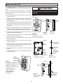
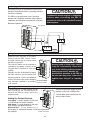
Operation and Installation Manual
Model
120ERV
Models
150 ERV
200ERV
Energy Recovery Ventilator (ERV)
Installation and wiring to be in accordance with
CEC, NEC and local electrical codes.
Important: Read and save these instructions.
69-ERVND
0713
Table of Contents
CAUTION
Getting to Know your Energy Recovery Ventilator (ERV)
Selecting the Ventilation Rate that is Right for You
How the Dehumidistat Works
Glossary and Additional Information
Warranty........................................................................................3
The Lifestyle Ventilation Control Part #99-BC01 ........................4
The Lifestyle Digital Control Part # 99-DX01(Optional).............5
Before installation, careful consideration must be
given to how this system will operate if connected
to any other piece of mechanical equipment, i.e. a
forced air furnace or air handler, operating at a
higher static. After installation, the compatibility of
the two pieces of equipment must be confirmed, by
measuring the air flows of the ERV, by using the
balancing procedure found in this manual.
NEVER install a ventilator in a situation where its
normal operation, lack of operation or partial
failure may result in the backdrafting or improper
functioning of vented combustion equipment.
The Lifestyle Digital Control Part # 99-DXPL01
Optional Timers ............................................................................6
The Lifestyle Programmable Control Part # 99-LS01 ..................7
Technical Data - Model 120ERV..................................................8
Technical Data - Model 150ERV..................................................9
Technical Data - Model 200ERV................................................10
Installation Methods....................................................................11
Installation Diagrams .............................................................12-17
Installation Requirements............................................................18
Suspend the Unit with the Adjustable Hanging Straps ...............19
Weatherhood Installation
Dual Hood Part #99-190 .............................................................20
Grilles ..........................................................................................21
Grille Fittings ..............................................................................22
Installation of the Main Control ..................................................23
Installation and Operation 20/40/60/ Minute Timers..................24
WARNING
• Disconnect the power from the unit before
cleaning or servicing.
• To prevent electrical shock, it is extremely
important to confirm the polarity of the power line
that is switched by the safety (disconnect) switch.
The hot line (black) is the proper line for switching.
Use either a voltmeter or test lamp to confirm the
absence of a voltage between the disconnect
switch and ground (on the cabinet) while the door
is open. This procedure must be followed, as
dwellings are occasionally wired improperly.
Always enure the proper grounding of the unit.
Interlocking the ERV Operation to an Airhandler/Furnace Blower
Setting “Standby” when using a Main Control
Operating the ERV without a Main Control
and Adding Dry Contact Controls...............................................25
Balancing the Air Flows..............................................................26
Balancing the Air Flows with a Pitot Tube .................................27
Balancing Collar Instructions (150ERV and 200ERV) ..............28
Maintenance Routine for ERV....................................................29
Troubleshooting your ERV System ............................................30
Wiring Diagrams....................................................................31-32
ATTENTION
• Do not apply electrical power to the unit until after
the completion of the installation (including the
installation of low voltage control wiring).
• Ensure the Installation and wiring is in
accordance with CEC, NEC, and local electrical
codes.
• Due to ongoing research and product
development, specifications, ratings and
dimensions are subject to change without notice.
• Plug the unit into a standard designated (120 VAC)
IMPORTANT PLEASE READ THIS MANUAL BEFORE
INSTALLING UNIT.
electrical outlet with ground.
NOTE
•The use of an extension cord with this unit is not
recommended. If the installation requires further
wiring, have a licensed electrician make all of the
electrical connections. The recommended circuit is a
separate 15 amp/120 volt circuit.
• Due to ongoing research and product
development, specifications, ratings and
dimensions are subject to change without notice.
2
Getting to Know your Energy Recovery Ventilator (ERV)
Thank you for purchasing a LIFEBREATH® Energy Recovery Ventilator
(ERV). The ERV provides fresh air to your home while recovering energy
from the air it exhausts.
There are numerous benefits to a properly installed, operated, and
maintained ERV:
• exhausts the stale, contaminated air, found in today’s tight buildings.
• recovers the majority of the energy contained in the exhausted stale air.
• uses the recovered energy to preheat or precool the fresh outdoor air
introduced into the house.
• distributes the fresh air throughout your home.
Selecting the Ventilation Rate that is right for You
The modes of operation and speeds are used to adjust your indoor
ventilation rate. Experiment with the ventilation levels in your home to
evaluate the ideal amount of ventilation to suit your home and personal
preferences. Your Lifebreath ERV main control has
2 Modes of Operation* and 5 speeds on each mode.
I. CONTINUOUS VENTILATION
This mode of operation provides continuous ventilation within the home.
You may, for example, select Continuous Ventilation at a low speed (speeds
1 or 2) for normal operation and increase to a higher speed (speeds 3 to 5)
during increased activity levels, such as cooking and showering, etc.
II. 20 MINUTES ON, 40 MINUTES STANDBY
This mode of operation provides 20 minutes of ventilation each hour. You
can use this ventilation mode at low speed for low household activity levels
or when the home is unoccupied.
How the Dehumidistat Works
Installation Manual for instructions on how to set the dehumidistat.
The dehumidistat function should be set to OFF for all seasons except the
heating season, because a dehumidifying effect occurs only when the
outdoor air is dryer than the indoor air. Set the RH level to 80 to turn the
dehumidistat OFF. (Refer to the control instructions for information on how
to set the Dehumidistat).
High indoor humidity levels, during the heating season, have become a
problem in many well insulated, tight homes. Excessive condensation on the
windows is a visual sign of high indoor humidity levels. High indoor
humidity levels can result in mold and mildew and the eventual degradation
of the building structure itself.
Your ERV reduces indoor humidity levels when the outdoor air is drier than
the indoor air. These conditions usually occur during the heating season
when outdoor temperatures are less than 15°C (59°F). During the heating
season, the operation of the ERV may reduce indoor humidity levels
sufficiently to eliminate the need for further dehumidification.
If your home requires further dehumidification, use the dehumidistat feature
located on the main control. This feature aggressively addresses high indoor
humidity levels by initiating high speed ventilation when the indoor
humidity levels rise above the adjustable set point on the control.
Refer to the main control instructions located in the Operation and
Glossary and Additional Information
ERV - a Energy Recovery Ventilator (ERV) is designed to provide fresh air
into a building while exhausting an equal amount of stale air. During the
winter months, heat recovered from the stale air, before it is
exhausted to the outdoors, warms the incoming cold fresh air. During the
summer months, when the indoor space is air conditioned, the ERV helps to
cool the incoming fresh air with the cool exhausted stale air.
MAINTENANCE ROUTINE - Homeowner maintenance should be
performed as per "Maintenance Routine for ERV" located in the
Operation and Installation Manual.
SELF-TEST - Each time the ERV is powered/energized, the self-test
function automatically initiates. The ERV cycles through the available
speeds and tests the damper motor operation. The ERV defaults back to the
previous operational mode and speed selection after the self-test
(approximately 60 seconds in duration).
STANDBY (Speed 0) - The ERV is powered/energized and waiting for
ventilation to be initiated by either an external control (i.e. timer) or the
dehumidistat. Set the main control to speed 0 to set the ERV in standby.
TIMERS - These optional controls may be installed at specific exhaust
locations (bathrooms etc.) to initiate high speed ventilation.
OPERATION AND INSTALLATION MANUAL - Contains
instructions and important information regarding your ERV and controls.
You can download the manual at www.lifebreath.com.
Warranty
Register for your warranty at:
www.lifebreath.com or phone 1-855-247-4200 (toll free)
NOTE: Airia will require the ERV Model and Serial Number(s) for
the registration of your ERV.
Units carry a ten (10) year warranty on the enthalpic (ERV) core
and a five (5) year replacement parts warranty.
3
The Lifestyle Ventilation Control Part #99-BC01 (Optional Control for 120ERV only)
The Lifestyle RNC Ventilation Control offers ON/OFF, High
Speed/Low speed plus an electronic dehumidistat.
Instruction card
Key Features
• 2 Speed Fan setting (Low/High)
• Electronic Dehumidistat (disabled on 120ERV)
On
indicator
light
• Instruction Card is inserted in the control
• Slim-line design
Dehumidistat
Indicator LEDs
%
80
• Connect to 3 wire 20 gauge low voltage wire.
High Speed
Indicator LED
HIGH
Turning on the Control
20
Press and release the ON/OFF button. The "ON Indicator
Light" will illuminate.
High/Low
Speed
button
ON/OFF
button
Adjusting the Ventilation Speed
The unit will normally operate at low speed. Press and
release the SPEED button to initiate high speed ventilation.
The "High Speed Indicator LED" will illuminate.
Humidity Control
Dehumidistat is disabled on models 120ERV, 150ERV and
200ERV.
Note
*Install a jumper between 2 (ON) and 3 (RED) on
the HRV terminal block to configure the ON/OFF
button to ON/STANDBY. Refer to “Setting Standby
when using a Main Control” in this manual.
4
The Lifestyle Digital Control Part #99-DX01 (Optional Control for 120ERV only)
The Lifestyle Digital Control offers advanced features to
control your home's ventilation.
Instruction card
Key Features
Fan Speed
Indicator
• 2 Speed Fan setting (Low-1/High-2)
• Standby setting (Fan speed 0)
Humidity
Indicator
20/40/60 Minute
High Speed
override Button
• Electronic Dehumidistat (disabled on models 150ERV and
200ERV)
Up Button
Mode Select
Button
• Two Selectable Modes of Operation
20 min. ON / 40 min. OFF
Mode
Indicator
Continuous Ventilation
• 20 / 40 /60 High Speed override button
ON/OFF
Button
• Instruction Card is inserted in the control
Set button
Down Button
High Speed
Override
Timer
Indicator
• Easy to read LCD Screen
• Slim-line design
• Connect to 3 wire 20 gauge low voltage wire
Connects to 3 wire 20 gauge
low voltage wire
Setting the Control
1. Refresh the screen: use the ON/OFF button to turn the
control OFF and ON.
The Lifestyle Digital Control Gives you
2 Mode Selection
2. Press the SET button.
3. The “FAN” symbol flashes. SCROLL (by using the
Up/Down arrows) to select the desired fan speed
(0, 1 or 2). Press the SET button.
The Lifestyle Digital Control has 2 Operational Modes* and
2 speeds on each mode to adjust indoor ventilation levels.
Experiment with the ventilation levels in your home to
evaluate the best amount of ventilation to suit your home
and preferences.
4. “VENT”, “20/40”, “20/40 RECIRC”, “RECIRC”or “OFF”
will flash. SCROLL to select the desired mode of
operation.
Press
SET
button.
*RECIRC is not available on all models.
**Timers will not function when mode of operation is set
to “OFF”.
I.
Continuous Ventilation Mode
This is the most popular mode since it provides
continuous ventilation within the home. You may, for
example, select Continuous Ventilation at high speed
for high household activity levels or Continuous
Ventilation for lower activity levels.
Setting the Dehumidistat
The dehumidistat is disabled on models 120ERV, 150ERV
and 200ERV.
II. 20 minutes ON, 40 minutes OFF Mode
20/40/60 Minute High Speed Timer
This Operational Mode will provide 20 minutes of
ventilation each hour. You may wish to use this
ventilation mode in low speed for low household activity
levels or if the home is unoccupied.
This function temporarily initiates high speed ventilation for
20, 40 or 60 minutes.
1. Refresh the screen: use the ON/OFF button to turn the
control OFF and ON.
2. Press FAN button once for 20, two times for 40, three
times for 60 minutes, and four times to cancel the timer.
5
The Lifestyle Digital Control Part # 99-DXPL01 (Wall Control included with 150ERV and 200ERV only)
Instruction card
The Lifestyle Digital Control is fully digital and allows you
to easily control your home's ventilation.
Fan Speed
Indicator
Key Features
Humidity
Indicator
20/40/60 Minute
High Speed
Override Button
• 5 Speed Fan setting
• Electronic Dehumidistat (disabled on models 150ERV and
200ERV)
Up Button
Mode Select
Button
• Two Selectable Modes of Operation
Set button
Mode
Indicator
20 min. ON / 40 min. off
Continuous Ventilation
ON/OFF
Button
• 20 / 40 /60 High Speed override timer
• Service/Maintenance Reminder display
Down Button
High Speed
Override
Timer
Indicator
• Backlit LCD screen is easy to read
Setting the Control
1. Refresh the screen: use the ON/OFF button to turn the
control OFF and ON.
Service
Indicator
Connects to 3 wire 20 gauge
low voltage wire
2. Press the SET button.
2. Press FAN button once for 20, two times for 40, three
times for 60 minutes, and four times to cancel the timer.
3. The “FAN” symbol flashes. SCROLL (by using the
Up/Down arrows) to select the desired fan speed
(0, 1 or 2). Press the SET button.
Service Indicator
4. “VENT”, “20/40” or “OFF” will flash. SCROLL to select
the desired mode of operation. Press SET button. .
**Timers will not function when mode of operation is set
to “OFF”.
A ‘SERVICE’ indicator displays once every 4 months. Refer
to "Maintenance Routine" in the Operation & Installation
manual.
Setting the Dehumidistat
To reset the service indicator:
The dehumidistat is disabled on models 150ERV and
200ERV.
1. Refresh the screen: use the ON/OFF button to turn the
control OFF and ON.
20/40/60 Minute High Speed Timer
2. Press and release the Up and Down buttons
simultaneously. The “SERVICE” icon will flash for
5 seconds.
This function temporarily initiates high speed ventilation for
20, 40 or 60 minutes.
3. Press SET within the 5 seconds and the service indicator
will reset.
1. Refresh the screen: use the ON/OFF button to turn the
control OFF and ON.
Optional Timers (for all ERV models)
The timer will override the Operational Mode (regardless of
the setting) and initiate high speed ventilation. Upon
completion of the timer cycle, the ERV will return to your
selected Operational Mode and speed setting.
Lifestyle 20/40/60 Minute Timer
Part # 99-DET01
Initiates high speed ventilation for 20, 40 or 60 minutes. The
20/40/60 Minute Status Lights indicate high speed operation.
Lockout Mode is useful if you wish to disable the timer. Set
lockout by holding the Select Button for 5 seconds. Unlock by
holding for 5 seconds.
20/40/60 Minute
Status Lights
Select Button
Connect to 3 wire 20 gauge low voltage wire. Mounts in a
standard 2" x 4" electrical box.
Lifestyle 20 Minute Timer
Part # 99-20M01
Initiates high speed ventilation for 20 minutes. The 20 Minute
Status Light indicates high speed operation.
20 Minute
Status Lights
Lockout Mode is useful if you wish to disable the timer. Set
lockout by holding the select button for 5 seconds. Unlock by
holding for 5 seconds.
Connect to 3 wire 20 gauge low voltage wire. Mounts in a
standard 2" x 4" electrical box.
6
Select Button
The Lifestyle Programmable Control Part # 99-LS01 (Optional for 150ERV and 200ERV only)
The optional Lifestyle Programmable Control is fully digital and
allows you to program when and how much fresh air will be entering
your home.
Key Features
• 24 / 7 programmable ventilation • 4 programmable events per
day
• 5 Speed Fan setting • Electronic Dehumidistat (disabled on
models 150ERV and 200 ERV)
• Two Selectable Modes of Operation
20 min. ON / 40 min. OFF
Continuous Ventilation
• 20 / 40 /60 High Speed override timer
• Service/Maintenance Reminder display
• Easy to read Backlit LCD screen
Instruction card
Fan Speed
Indicator
Date & Time
20/40/60 Minute
High Speed
Override Button
Humidity
Indicator
Mode Select
Button
Up Button
Set button
Mode
Indicator
Decrease
Button
ON/OFF
Button
Service
Indicator
High Speed
Override
Timer
Indicator
Setting Date & Time
1. Refresh the screen: use the ON/OFF button to turn the control
OFF and ON.
2. Press and release the MODE button until "TIME" and "SET"
appear on the screen. Press SET Button.
3. The letter for the day of the week flashes. SCROLL (using
Up/Down arrows) to the correct day of the week. Press the SET
button.
4. The hour and "AM" or "PM" flashes. SCROLL to the correct
hour and press the SET button.
5. The minutes will flash. SCROLL to the correct minute. Press the
SET button.
Connects to 3 wire 20 gauge
low voltage wire
Daytime
Event
Program
Indicator
ATTENTION
Only one main control can be installed on your system.
Running the Program
Upon completion of the programming, you must activate the
program.
1. Refresh the screen: use the ON/OFF button to turn the control
OFF and ON.
2. Press MODE until the program indicates “PROGRAM” and
“RUN”.
Programming Your Control
1. Refresh the screen: use the ON/OFF button to turn the control
OFF and ON.
2. Press and release the MODE button until "PROGRAM SET"
appears on the screen. Press SET.
3. Weekday letters (MTWTF) will flash. Press SET.
4. "WAKE" flashes. Press SET.
5. "AM" or "PM" flashes. SCROLL to desired time (in 20 minute
intervals). Press SET.
6. The "FAN" symbol flashes. SCROLL to the desired fan speed
(0-5). Press SET.
7. “VENT”, “20/40”or “OFF” will flash. SCROLL to the desired
mode of operation. Press SET twice.
8. "LEAVE" flashes. Press SET. Repeat steps 4 to 6 to program
four events per day.
9. “SS” (Saturday & Sunday) flashes. Press SET. Repeat steps
3 to 7 to program the weekend events.
Manually Setting the Control
1.
Refresh the screen: use the ON/OFF button to turn the control
OFF and ON.
2. Press and release MODE until the program indicates "MANUAL"
and "RUN”. Press SET.
3. When the FAN symbol flashes, SCROLL (use the Up/Down
arrows) to the desired fan speed (0-5). Press SET.
4. VENT, 20/40 or OFF will flash. SCROLL to the desired mode of
operation. Press SET.
NOTE: The control remains in the “MANUAL RUN” position until you
change back to “PROGRAM RUN” (Refer to “Running the
Programmed Setting).
**Timers will not function when mode of operation is set to
“OFF”.
Setting the Dehumidistat
Programming Individual Weekday Events
Dehumidistat is disabled on 120ERV, 150ERV and 200ERV).
After performing the MTWTF and SS programming functions, you
can program individual weekday events.
1. Refresh the screen: use the ON/OFF button to turn the control
OFF and ON.
2. Press and release the MODE Button until "PROGRAM SET"
appears on the screen. Press SET.
3. Weekday letters (MTWTF) will flash. Scroll to the desired
weekday (M,T,W,T,F,S,S). Press SET.
4. “WAKE” flashes. Scroll to the desired event that you want to
program as a custom setting (“WAKE”, “AWAY”, “RETURN” or
“SLEEP”. Press SET.
5. Either “AM” or “PM” flashes. SCROLL to the desired time
(available in 20 minute intervals). Press SET.
6. “FAN” flashes. SCROLL to desired fan speed (0 - 5). Press SET.
7. “VENT”, “20/40” or “OFF” will flash. SCROLL to the desired mode
of operation. Press SET. (Refer to Manual for explanation of
operational modes.)
8. More weekday events are programmable by pressing SET and
repeating steps 4 to 7.
20/40/60 Minute High Speed Timer
This function temporarily initiates high speed ventilation for 20, 40 or
60 minutes.
1. Refresh the screen: use the ON/OFF button to turn the control
OFF and ON.
2. Press the FAN button once for 20, twice for 40 and three times
for 60 minutes and four times to cancel the timer.
Service Indicator
A ‘SERVICE’ indicator displays once every 4 months. Refer to
"Maintenance Routine" in the Operation & Installation manual.
To reset the service indicator:
1. Refresh the screen: use the ON/OFF button to turn the control
OFF and ON.
2. Press and release the Up and Down buttons simultaneously. The
“SERVICE” icon will flash for 5 seconds.
3. Press SET within the 5 seconds and the service indicator will
reset.
7
Model 120ERV
ENGINEERING DATA
DIMENSIONS 120ERV inches (mm)
Performance (HVI certified)
Net supply air flow in cfm (L/s) against external static pressure
E.S.P
(external static pressure)
[cfm (L/s)]
@ 0.1" (25 Pa)
@ 0.2" (50 Pa)
@ 0.3" (75 Pa)
@ 0.4" (100 Pa)
@ 0.5" (125 Pa)
@ 0.6" (150 Pa)
@ 0.7" (175 Pa)
@ 0.8" (200 Pa)
119 (56)
113 (53)
108 (51)
103 (49)
98 (46)
93 (44)
88 (42)
83 (39)
Sensible Effectiveness
@ 64 cfm (30L/s)
*Sensible Efficiency
32°F (0°C)
74
@ 64 cfm (30L/s)
32°F (0°C)
62
Total Efficiency
@ 64 cfm (30L/s)
95°F (35°C)
35
VAC @ 60HZ
120
WATTS / Low speed.
69
WATTS / High speed
147
Amp rating
1.7
*Sensible Efficiency – thermal **Latent Efficiency – moisture
Note: Effectiveness - based on temp. differential between the 2 airstreams
Efficiency – takes into account all power inputs
140
HI 3
120
HI 2
100
HI 1
Air Flow (cfm)
LATENT RECOVERY/MOISTURE TRANSFER CORE
The counter-flow energy recovery core transfers heat and water vapor between the two
airstreams. It is easily removed for cleaning or service.
MOTORS AND BLOWERS
Each air stream has an independent motorized impeller with two speed operation.
FILTERS
Washable air filters in exhaust and supply air streams.
MOUNTING THE ERV
Adjustable height “L” bracket supplied.
DEFROST
Fan defrost system.
CASE
Twenty gauge prepainted galvanized steel (G60) for superior corrosion resistance. Insulated
to prevent exterior condensation.
WEIGHT 38 lbs. (17.2 kg) SHIPPING WEIGHT 41 lbs. (18.6 kg)
ELECTRONICS
Unit is supplied with a removable electrical box which can be accessed through the main door
of the ERV.
OPTIONAL CONTROLS
The optional controls can be wall mounted in a central location of the home.
99-BC-01 Lifestyle RNC Ventilation Control
Can be wall mounted in a central location of the home (3 wire) 20 gauge 100 ft. length.
• 2 Speed Fan setting (Low/High)
•Adjustable Dehumidistat function built into main wall control.
•Built-in Relay for interlocking the unit to furnace.
99-DX01 Lifestyle RNC Digital Control
• 2 Speed Operation on each mode
• 2 user selectable operational modes: Continuous
Ventilation, 20 ON/40 OFF
• Connect to 3 wire 20 gauge low voltage wire.
OPTIONAL TIMERS
99-DET01 Lifestyle 20/40/60 Minute Timer - Initiates high speed ventilation for 20, 40 or
60 minutes, (3 wire) 20 gauge wire (min.) 100 ft. length
99-20M01 Lifestyle 20 Minute Timer - Initiates high speed ventilation for 20 minutes,
(3 wire) 20 gauge wire (min.) 100 ft. length.
99-101
Mechanical Timer - Initiates High speed ventilation for up to 60 minutes, (2 wire)
20 gauge wire (min.) 100 ft. length
OPTIONAL ACCESSORIES
99-190
Dual Hood - One 6” opening for supply and exhaust
99-185
Weatherhood Kit - Two - 5” labelled Supply & Exhaust, c/w sleeve, collar,
1/4” (6 mm) mesh screen
80
LOW
60
40
20
33”
(838 mm)
All duct connections are 5” (125 mm)
28 5/8”
(727 mm)
9 1/4”
(235 mm)
17”
(432 mm)
FRESH AIR
FROM
OUTSIDE
18 1/4 “
(464 mm)
0.2
0.4
0.6
0.8
1.0
1.2
Static Pressure (in w.g.)
INSTALLER SELECTABLE HIGH SPEED SETTINGS
Adjustable DIP switches are located on the circuit board. Hi3
is the factory setting. Refer to the Operation and Installation
manual for the adjustment instructions.
Access Door
STALE AIR TO
OUTSIDE
BOTTOM VIEW
0
All units conform to CSA and UL standards.
FRESH AIR TO
BUILDING
STALE AIR
FROM
BUILDING
0
OUTLET END VIEW
WARRANTY
Units carry a ten (10) year warranty on the enthalpic (ERV)
core and a five (5) year replacement parts warranty.
Date: ___________________________________________
Contractor: ______________________________________
Tag: _____________________Qty:___________________
Supplier: ________________________________________
Project: _________________________________________
Quote#: _________________________________________
Engineer: _______________________________________
Submitted by: ____________________________________
T 1-855-247-4200
F 1-800-494-4185
[email protected]
8
Model 150ERV
ENGINEERING DATA
CONTROLS & ELECTRONICS
The Lifestyle Digital Control (included with unit) can be wall mounted in a central
location of the home. (3 wire) 20 gauge wire (min.) 100' length
Electronic features include:
• 5 Speed Operation on each mode
• 2 user selectable operational modes: Continuous Ventilation, 20 ON/40 OFF
• Built-in Relay for Interfacing to furnace
• Service Reminder
• 20, 40, 60 Minute Override Timer
• Dehumidistat Disable Feature
OPTIONAL PROGRAMMABLE CONTROL
99-LS01
Lifestyle Programmable Control - contains all the features of the
Lifestyle Digital Control with 7/24 programmable ventilation,
(3 wire) 20 gauge wire (min.) 100' length
OPTIONAL TIMERS
99-DET01 Lifestyle 20/40/60 Minute Timer - Initiates high speed ventilation for
20, 40, or 60 minutes. (3 wire) 20 gauge wire (min.) 100' length
99-20M01 Lifestyle 20 Minute Timer - Initiates high speed ventilation for
20 minutes, (3 wire) 20 gauge wire (min.) 100’ length.
OPTIONAL ACCESSORIES
99-186
Weatherhood Kit - Two - 6” (150mm), labelled Supply & Exhaust, c/w
sleeve, collar, 1/4 (6mm) mesh screen
DIMENSIONS 150ERV
Performance (HVI Certified)
Net supply air flow in cfm (L/s) against external static pressure
E.S.P
(external static pressure)
[cfm (L/s)]
@ 0.1" (25 Pa)
151 (71)
@ 0.2" (50 Pa)
141 (67)
@ 0.3" (75 Pa)
132 (62)
@ 0.4" (100 Pa)
124 (59)
@ 0.5" (125 Pa)
107 (50)
@ 0.6" (150 Pa)
98 (46)
@ 0.7" (175 Pa)
81 (38)
@0.8 " (200 Pa)
60 (28)
Sensible Effectiveness
@ 64 cfm (30 L/s)
*Sensible Efficiency
@ 64 cfm (30 L/s)
32°F (0°C)
81%
32°F (0°C)
69%
Total Efficiency
@ 64 cfm (30L/s)
95°F (35°C)
47%
VAC @ 60HZ
120
WATTS / Low speed
70
WATTS / High speed
108
Amp rating
1.4
*Sensible Efficiency – thermal
Note: Effectiveness - based on temp. differential between the 2 airstreams
Efficiency – takes into account all power inputs
220
5 - High Speed
4 - High Medium Speed
3 - Medium Speed
2 - Medium Low Speed
1 - Low speed
200
180
160
Air Flow (cfm)
LATENT RECOVERY/MOISTURE TRANSFER CORE
The counter-flow energy recovery core transfers heat and water vapor between the
two airstreams. It is easily removed for cleaning or service.
MOTORS AND BLOWERS
Each air stream has one centrifugal blower driven by a common PSC motor.
5 speed fan operation.
FILTERS
Washable air filters in exhaust and supply air streams.
MOUNTING THE ERV
Four threaded inserts at corners of the cabinet designed to accept the “S” hooks and
hanging straps supplied with the unit.
CASE
Twenty gauge prepainted galvanized steel (G60) for superior corrosion resistance.
Insulated to prevent exterior condensation. Door balancing ports.
WEIGHT 75 lbs. (34Kg)
SHIPPING WEIGHT 77lbs. (35Kg)
DEFROST—not available on this model
Speed 5
140
Speed 4
120
100
Speed 3
80
Speed 2
60
Speed 1
40
inches (mm)
20
* All Duct Connections 6"(150mm)
MOTOR
BALANCING
DAMPER
BALANCING
DAMPER
FILTERS
CORE
FRESH AIR
FROM OUTSIDE
33-5/8"
(850)
0
0.1
0.2
0.3
0.4
0.5
Static Pressure (in w.g.)
0.6
0.7
0.8
FRESH AIR
TO INSIDE
19"
(483)
ENTHALPIC CORE
STALE AIR
FROM INSIDE
All units conform to CSA and UL standards.
*NOTE: Front clearance
of 25 inches (635 mm)
is recommended
for servicing unit.
STALE AIR
TO OUTSIDE
14 3 / 4 "
(375)
BLOWERS
Date: ___________________________________________
WARRANTY
Units carry a tem (10) year warranty
on the enthalpic (ERV) core and a five
(5) year replacement parts warranty.
Contractor: ______________________________________
Tag: _____________________Qty:___________________
Supplier: ________________________________________
Project: _________________________________________
Quote#: _________________________________________
Engineer: _______________________________________
Submitted by: ____________________________________
T 1-855-247-4200
F 1-800-494-4185
[email protected]
9
Model 200ERV
ENGINEERING DATA
CONTROLS & ELECTRONICS
The Lifestyle Digital Control (included with unit) can be wall mounted in a central
location of the home. (3 wire) 20 gauge wire (min.) 100' length
Electronic features include:
• 5 Speed Operation on each mode
• 2 user selectable operational modes: Continuous Ventilation, 20 ON/40 OFF
• Built-in Relay for Interfacing to furnace
• Service Reminder
• 20, 40, 60 minute Override Timer
• Dehumidistat Disable Feature
OPTIONAL PROGRAMMABLE CONTROL
99-LS01
Lifestyle Programmable Control - contains all the features of the
Lifestyle Digital Control with 7/24 programmable ventilation,
(3 wire) 20 gauge wire (min.) 100' length
OPTIONAL TIMERS
99-DET01 Lifestyle 20/40/60 Minute Timer - Initiates high speed ventilation for
20, 40, or 60 minutes. (3 wire) 20 gauge wire (min.) 100' length
99-20M01 Lifestyle 20 Minute Timer - Initiates high speed ventilation for
20 minutes, (3 wire) 20 gauge wire (min.) 100’ length.
OPTIONAL ACCESSORIES
99-186
Weatherhood Kit, Two — 6” (150 mm), labelled Supply & Exhaust,
c/w sleeve, collar, 1/4” (6 mm) mesh screen
Performance (HVI Certified)
Net supply air flow in cfm (L/s) against external static pressure
E.S.P
(external static pressure)
[cfm (L/s)]
@ 0.1" (25 Pa)
180 (85)
@ 0.2" (50 Pa)
169 (80)
@ 0.3" (75 Pa)
157 (74)
@ 0.4" (100 Pa)
146 (69)
@ 0.5" (125 Pa)
132 (62)
@ 0.6" (150 Pa)
118 (56)
@ 0.7" (175 Pa)
101 (48)
Sensible Effectiveness
@ 116 cfm (55 L/s)
*Sensible Efficiency
@ 116 cfm (55 L/s)
32°F (0°C)
76%
32°F (0°C)
69%
Total Efficiency
50%
VAC @ 60HZ
120
WATTS / Low speed
68
WATTS / High speed
97
Amp rating
1.4
*Sensible Efficiency – thermal
Note: Effectiveness - based on temp. differential between the 2 airstreams
Efficiency – takes into account all power inputs
220
5 - High Speed
4 - High Medium Speed
3 - Medium Speed
2 - Medium Low Speed
1 - Low speed
200
Speed 5
180
160
Air Flow (cfm)
LATENT RECOVERY/MOISTURE TRANSFER CORE
The counter-flow energy recovery core transfers heat and water vapor between the
two airstreams. It is easily removed for cleaning or service.
MOTORS AND BLOWERS
Each air stream has one centrifugal blower driven by a common PSC motor.
5 speed fan operation.
FILTERS
Washable air filters in exhaust and supply air streams.
MOUNTING THE ERV
Four threaded inserts at corners of the cabinet designed to accept the “S” hooks and
hanging straps supplied with the unit.
CASE
Twenty gauge prepainted galvanized steel (G60) for superior corrosion resistance.
Insulated to prevent exterior condensation. Door balancing ports.
WEIGHT 75 lbs. (34Kg)
SHIPPING WEIGHT 77lbs. (35Kg)
DEFROST—not available on this model
Speed 4
140
Speed 3
120
Speed 2
100
Speed 1
80
60
40
ENTHALPIC CORE
STALE AIR
FROM INSIDE
20
inches (mm)
* All Duct Connections 6"(150mm)
MOTOR
BALANCING
DAMPER
CORE
FRESH AIR
FROM OUTSIDE
33-5/8"
(850)
0.1
0.2
0.3
0.4
0.5
Static Pressure (in w.g.)
0.6
0.7
0.8
FRESH AIR
TO INSIDE
BALANCING
DAMPER
FILTERS
0
19"
(483)
DIMENSIONS 200ERV
All units conform to CSA and UL standards.
*NOTE: Front clearance
of 25 inches (635 mm)
is recommended
for servicing unit.
STALE AIR
TO OUTSIDE
14 3 / 4 "
(375)
BLOWERS
WARRANTY
Units carry a tem (10) year warranty
on the enthalpic (ERV) core and a five
(5) year replacement parts warranty.
Date: ___________________________________________
Contractor: ______________________________________
Tag: _____________________Qty:___________________
Supplier: ________________________________________
Project: _________________________________________
Quote#: _________________________________________
Engineer: _______________________________________
Submitted by: ____________________________________
T 1-855-247-4200
F 1-800-494-4185
[email protected]
10
Installation Methods
The Three Methods of Installation
Installing the Ducting Between the ERV and Living
Areas in the House
The three methods of installation for the ERV system are:
• The Simplified installation.
A well designed and installed ducting system will allow the
ERV to operate at its maximum efficiency.
• The Partially Dedicated Installation
All ducts should be kept short and have as few bends or
elbows as possible to maximize airflow. Forty-five degree
elbows are preferred to 90° elbows. Use "Y" tees instead of
straight tees whenever possible.
• The Fully Dedicated Installation
Simplified Installations
The Simplified Installation draws stale air from the cold air
return duct of the air handler/furnace and introduces an
equal amount of fresh air farther downstream into the cold
air return. Refer to "Simplified Installation Diagrams".
All duct joints must be fastened with screws, rivets or duct
sealant and wrapped with mastic or quality duct tape to
prevent leakage. Mastic is preferred but if duct tape is used,
we recommend aluminum foil duct tape.
The air handler/furnace blower must be running when the
unit is operating for this system to be effective. Refer to
"Interlocking the ERV to an Air handler/Furnace Blower".
Partially Dedicated Installations
Galvanized (rigid) ducting from the ERV to the living areas in
the house is recommended whenever possible although
flexible duct can be used in moderation if necessary.
The Partially Dedicated Installation draws stale air from
specific points in the house and introduces an equal amount
of fresh air into the cold air return. Refer to "Partially
Dedicated Installation Diagrams".
A short length (approximately 12 inches or 300mm) of nonmetallic flexible insulated duct should be connected between
the ERV and the supply/exhaust duct system to avoid
possible noise transfer through the duct system.
Stale air ducts should be installed in areas of the home
where the poorest indoor air quality exists (bathrooms and
kitchen). Each location with a stale air duct should have a
timer to initiate high speed ventilation. Refer to "Optional
Timers" in this manual.
All ducts running through attics and unheated spaces must
be sealed and insulated to code.
WARNING
The air handler/furnace blower should be running when the
ERV is operating to evenly distribute the fresh air
throughout the house. Refer to "Interlocking the ERV to an
Air handler/Furnace Blower".
Include a short length of fabric flex duct or other
non-metallic connector in this hard ducted line in
order to keep the ERV separately grounded
(electrically) from the air handler.
Fully Dedicated Installations
The Fully Dedicated Installation draws stale air from specific
points in the house and delivers fresh air to specific locations
of the house. This system is not connected to an air
handler/furnace. Refer to "The Fully Dedicated Installation
Diagrams" in this manual.
ATTENTION
Stale air ducts should be installed in areas of the home
where the poorest indoor air quality exists (bathrooms and
kitchen). Each location with a stale air duct should have a
timer which will initiate high speed ventilation. Refer to
"Optional Timers" in this manual.
Applications such as greenhouses, atriums,
swimming pools, saunas, etc. have unique
ventilation requirements which should be
addressed with an isolated ventilation system.
Fresh air ducts should be installed to all bedrooms and living
areas, excluding bathrooms, kitchen and utility areas. Grilles
should be located high on a wall or in ceiling locations.
Grilles that diffuse the air comfortably are recommended.
Refer to "Grilles" in this manual.
11
Simplified Installation Diagrams (150ERV and 200ERV)
Simplified Installation (Return/Return Method)
Key Points
• The ERV must be balanced.
• It is mandatory that the furnace blower run
continuously or ERV operation be interlocked with
the furnace blower.
• The duct configuration may change depending on
the ERV model. See specifications for your unit.
• Check local codes / authority having jurisdiction for
acceptance.
• A backdraft damper is required in the exhaust air
duct to prevent outdoor air from entering the unit
when the Furnace/Airhandler is running and the unit
is in either Standby or OFF.
Sizing the Ductwork
It is the responsibility of the installer to ensure all
ductwork is sized and installed as designed to ensure
the system will perform as intended.
The amount of air (cfm) that an ERV will deliver is
directly related to the total external static pressure
(E.S.P.) of the system. Static pressure is a measure of
resistance imposed on the blower by length of duct
work plus the number of fittings used in the duct work.
DIRECT CONNECTION of both the ERV SUPPLY AIR STREAM and
EXHAUST AIR STREAM to the FURNACE COLD AIR RETURN
RETURN AIR
40” (1 m) MINIMUM
3' min.
recommended
Dampers for balancing air flows
Stale Air to
Outside
Fresh Air from
Outside
Spring Loaded Backdraft Damper
Forced Air
Furnace
Spring-Loaded Backdraft Damper
Install the Backdraft Damper with the leaf hinge vertical.
The damper is installed on the “Stale Air to Outside Collar”.
6” (152mm) Backdraft Damper Part No. 99-RSK6
WARNING
Installation Notes
• Unit is normally balanced on HIGH speed with the furnace blower ON.
• A minimum separation of 40 inches (1m) is recommended between the
two direct connections.
• The exhaust air connection should be upstream of the supply air
connection to prevent exhausting any fresh air.
• Weatherhood arrangement is for drawing purposes only. Six feet (2m)
minimum separation is recommended. The Weatherhood must also be
18" (460mm) above grade minimum.
• The airflow must be confirmed on site using the balancing procedures
found in this manual.
12
The Stale Air to Outside air duct requires
a Backdraft Damper. This damper prevents
outdoor air from entering the ERV
during the operation of the Furnace/
Airhandler while the ERV is in either
standby or OFF.
Partially Dedicated Installation Diagrams (150ERV and 200ERV)
Partially Dedicated System
This installation enables stale air to be drawn from the
poorest air quality areas of the home (bathrooms,
kitchen).
Key Points
• The ERV must be balanced.
• It is recommended that the furnace blower run
continuously or ERV operation be interlocked with the
furnace blower to evenly distribute the fresh air
throughout the house.
• The duct configuration may change depending on the
ERV model. See specifications for your unit.
• Check local codes / authority having jurisdiction for
acceptance.
• A backdraft damper is required in the exhaust air duct
to prevent outdoor air from entering the unit when the
Furnace/Airhandler is running and the unit is in either
Standby or OFF.
Sizing the Ductwork
It is the responsibility of the installer to ensure all
ductwork is sized and installed as designed to ensure
the system will perform as intended.
The amount of air (cfm) that an ERV will deliver is
directly related to the total external static pressure
(E.S.P.) of the system. Static pressure is a measure of
resistance imposed on the blower by length of duct work
plus the number of fittings used in the duct work.
DIRECT CONNECTION of the SUPPLY AIR STREAM to the FURNACE COLD AIR RETURN
(Stale air drawn from key areas of the home)
Exhaust Air from different
areas of the home
(bathrooms, kitchen)
RETURN AIR
3' min.
recommended
Dampers for balancing air flows
Stale Air to
Outside
Fresh Air from
Outside
Spring Loaded Backdraft Damper
Forced Air
Furnace
Spring-Loaded Backdraft Damper
Install the Backdraft Damper with the leaf hinge vertical.
The damper is installed on the “Stale Air to Outside Collar”.
6” (152mm) Backdraft Damper Part No. 99-RSK6
WARNING
Installation Notes
• Unit is normally balanced on HIGH speed with the furnace blower ON.
• A minimum separation of 40 inches (1m) is recommended between the
two direct connections.
• The exhaust air connection should be upstream of the supply air
connection to prevent exhausting any fresh air.
• Weatherhood arrangement is for drawing purposes only. Six feet (2m)
minimum separation is recommended. The Weatherhood must also be
18" (460mm) above grade minimum.
• The airflow must be confirmed on site using the balancing procedures
found in this manual.
13
The Stale Air to Outside air duct requires
a Backdraft Damper. This damper prevents
outdoor air from entering the ERV during
the operation of the Furnace/Airhandler
while the ERV is in either standby or OFF.
Fully Dedicated Installation Diagrams (150ERV and 200ERV)
Fully Dedicated System
This is a stand alone ERV system which is not
connected to a force air system. Stale air is drawn
from key areas of the home (bathroom, kitchen)
while fresh air is supplied to main living areas
Key Points
• The ERV must be balanced.
• The duct configuration may change depending
on the ERV model. See specifications for your
unit.
• Check local codes / authority having jurisdiction
for acceptance.
Fresh air to house main living areas,
bedrooms, livingroom,
recreation room, etc.
Stale Air from various
areas of the home
(bathrooms, kitchen)
Dampers for balancing air flows
Stale Air to
Outside
Fresh Air from
Outside
Installation Notes
• Weatherhood arrangement is for drawing purposes only. Six feet (2m)
minimum separation is recommended. The Weatherhood must also be
18" (460 mm) above grade minimum.
• The airflow must be confirmed on site using the balancing procedures
found in this manual.
14
Simplified Installation Diagrams (120ERV)
Key Points
Sizing the Ductwork
• The ERV must be balanced.
• It is mandatory that the furnace blower run
continuosly or ERV operation be interlocked
with the furnace blower.
• The duct configuration may change depending on
the ERV model. See specifications for your unit.
• Check local codes / authority having jurisdiction for acceptance.
• A backdraft damper is required in the exhaust air duct to prevent
outdoor air from entering the unit when the Furnace/Airhandler is
running and the unit is in either Standby or OFF.
The installer must ensure that all duct work is
sized and installed as designed to ensure the
system will perform as intended.
The amount of air (cfm) that an ERV will
deliver is directly related to the total external
static pressure (E.S.P.) of the system. Static
pressure is a measure of resistance imposed on
the blower by length of duct work plus the
number of fittings used in the duct work.
Exhaust Air
to Outside
*Unit is normally balanced on
HIGH speed with air handler
blower ON.
Return Air
40" (1m) MINIMUM
3' (915 mm)
MINIMUM
recommended
Fresh Air
from Outside
Damper for
balancing airflow
Damper for
balancing airflow
Install backdraft
damper to ERV
collar with leaf hinge
vertical
Spring-Loaded Backdraft Damper (Not Included)
Install the Backdraft Damper with the leaf hinge vertical.
The damper is installed on the “Stale Air to Outside Collar”.
5” (127 mm) Backdraft Damper No. 99-RSK5
Air
Handler
High efficiency filter
or electronic air cleaner
Installation Notes
• Unit is normally balanced on HIGH speed with the furnace blower ON.
• A minimum separation of 40 inches (1m) is recommended between the
two direct connections.
• The exhaust air connection should be upstream of the supply air
connection to prevent exhausting fresh air.
• Weatherhood arrangement is for drawing purposes only. Six feet (2m)
minimum separation is recommended. The Weatherhood must also be
a minimum of 18” (460 mm) above grade.
• The airflow must be confirmed on site using the balancing procedures
explained in this manual.
15
WARNING
A Backdraft Damper is required in the Stale
Air to Outside air duct to prevent outdoor air
from
entering
the
ERV
when
the
Furnace/Airhandler is operating and the ERV
is in either Standby or OFF.
Partially Dedicated Installation Diagrams (120ERV)
Key Points
Sizing the Ductwork
• The ERV must be balanced.
• It is mandatory that the furnace blower run
continuosly or ERV operation be interlocked
with the furnace blower.
• The duct configuration may change depending on
the ERV model. See specifications for your unit.
• Check local codes / authority having jurisdiction for acceptance.
• A backdraft damper is required in the exhaust air duct to prevent
outdoor air from entering the unit when the Furnace/Airhandler is
running and the unit is in either Standby or OFF.
The installer must ensure that all duct work is
sized and installed as designed to ensure the
system will perform as intended.
The amount of air (cfm) that an ERV will
deliver is directly related to the total external
static pressure (E.S.P.) of the system. Static
pressure is a measure of resistance imposed on
the blower by length of duct work plus the
number of fittings used in the duct work.
Exhaust Air
to Outside
Return Air
STALE AIR from various parts of home
(i.e. bathrooms and kitchens if required)
3' minimum
recommended
Fresh Air
from Outside
Damper for
balancing airflow
Damper for
Install backdraft
balancing airflow
damper to ERV
collar with leaf hinge
vertical
Spring-Loaded Backdraft Damper (Not Included)
Install the Backdraft Damper with the leaf hinge vertical.
The damper is installed on the “Stale Air to Outside Collar”.
5” (127 mm) Backdraft Damper No. 99-RSK5
Air
Handler
High efficiency filter
or electronic air cleaner
Installation Notes
• Unit is normally balanced on HIGH speed with the furnace blower ON.
• A minimum separation of 40 inches (1m) is recommended between the
two direct connections.
• The exhaust air connection should be upstream of the supply air
connection to prevent exhausting fresh air.
• Weatherhood arrangement is for drawing purposes only. Six feet (2m)
minimum separation is recommended. The Weatherhood must also be
a minimum of 18” (460 mm) above grade.
• The airflow must be confirmed on site using the balancing procedures
explained in this manual.
16
WARNING
A Backdraft Damper is required in the Stale
Air to Outside air duct to prevent outdoor air
from
entering
the
ERV
when
the
Furnace/Airhandler is operating and the ERV
is in either Standby or OFF.
Fully Dedicated Installation Diagrams (120ERV)
Fully Dedicated System for ERV
•
Stale air drawn from key areas of
home (bathroom, kitchen, laundry)
•
Fresh air supplied to main living
areas of home
WARNING
ERV must be balanced.
Outdoors
Exhaust Air
to Outside
STALE AIR from
various parts of home. Field-supplied Balancing Damper (optional)
i.e. bathrooms
(if required),
kitchens
(if required).
Fresh Air
from Outside
*Unit is normally balanced on HIGH speed
with air handler blower ON.
Fresh air to house main living areas...
bedrooms, living room,
rec. room etc.
CAUTION
Weather hood arrangement - a minimum of 6' (2m)
of separation is recommended and a minimum of 18"
(460mm) clearance above grade.
17
Installation Requirements (ERV)
WARNING
Before installation, careful consideration must be
given to how this system will operate if connected
to any other piece of mechanical equipment, i.e. a
forced air furnace or air handler, operating at a
higher static. After installation, the compatibility of
the two pieces of equipment must be confirmed, by
measuring the air flows of the ERV, by using the
balancing procedure found in this manual.
Connecting Appliances to the ERV
The following appliances should not be connected to the ERV:
• clothes dryer
• range top
• stove top exhaust fan
• central vacuum system
NOTE: Connecting any of these items to the ERV will invalidate
your warranty.
It is important to assess how the operation of an
ERV will interact with vented combustion
equipment (i.e. Gas Furnaces, Oil Furnaces, Wood
Stoves etc.).
NEVER install a ventilator in a situation where its
normal operation, lack of operation or partial
failure may result in the backdrafting or improper
functioning of vented combustion equipment.
Location Selection
Install the ERV in a space conveniently located for servicing the
unit. A typical location for the ERV is in a Mechanical room or in
an area close to the outside wall where the weatherhoods are
mounted. If a convenient area in the basement does not exist, a
utility or laundry room is acceptable.
WARNING
Improper installation, adjustment, alteration,
service or maintenance can cause property
damage, personal injury or loss of life.
Installation and service must be performed by
a qualified installer or service agency.
Install the unit in a horizontal position suspended with the hanging
straps provided. Leave sufficient clearance below the access door
for servicing the air filters and core.
WARNING
Electric shock hazard. Can cause
injury or death. Before attempting to
perform any service or maintenance,
turn the electrical power unit OFF at
disconnect switch(es). Unit may have
multiple power supplies.
18
Suspend the Unit with the Adjustable Hanging Straps (150ERV and 200ERV)
Use 4 screws and 4 washers (not incldued) to attach the hanging
straps to the floor joists. The washer must be wider than the eyelet
of the grommet on the hanging strap.
By design, the adjustable hanging straps reduce the possibility of
noise, resonance and harmonics.
STEP 3. Hook the bottom grommets of the straps through the "S"
hooks. Pull down vertically on the hand loops while lifting up the
bottom of the cabinet. Repeat at opposite end of the unit.
STEP 1. Insert the screws and washers (not included) through
the Hanging Strap grommets and fasten to the joists.
Joist
Hanging Strap grommets
Buckles
Washers (not included)
Hand Loops
Note: Do not pull the
Hand Loops in a
horizontal or lateral
direction during the
installation/adjustment
process.
Screws (not included)
Buckles
Pull down on the hand
loops while lifting
the bottom of the unit.
Hand Loops
STEP 4. Level the unit from left to right and front to back.
STEP 2. Unscrew the 4 machine screws located on the upper
side of the unit. Attach the "S" hooks and reinsert the machine
screws.
- Adjust the unit down by lifting up on the buckle.
- Adjust the unit up by pulling down vertically on the Hand
Loops while lifting up the bottom of the cabinet.
STEP 5. Fold the hand loops and excess strap and secure with a
nylon tie (not included).
DETAIL
Straps
Note: This illustration of the unit may
vary from the unit you are installing.
“S” hooks
Hand Loops
Suspending the RNC120F
Suspending the RNC120F
It is important to isolate the “L” BRACKET from the attached
surface to minimize vibration. Use the hardware provided to
attach the brackets. Do not drill additional holes in the HRV.
Adjustable height
“L” Brackets
ATTENTION
The unit must be mounted level for proper
drainage of the condensate pans.
19
Weatherhood Installation (ERV)
Lifebreath Weatherhoods
Available Parts
5” (125 mm) Part No. 99-185
6” (150 mm) Part No. 99-186
7” (200 mm) Part No. 99-187
Fixed, covered weatherhoods include a 1/4” (6mm) screen
to prevent foreign objects from entering the duct work.
Hoods are labelled Supply and Exhaust. The kit also
includes 2 sleeve of pipe and 2 collars.
WEATHERHOOD INSTALLATION
Weatherhood Clearances
OUTSIDE CORNER
36" (1m)
recommended min.
COLLAR IS SUPPLIED TO
ENSURE VAPOUR BARRIER
IS 100% SEALED TO
WALL PLATE
SCREEN
(side view)
36" (1m)
recommended min.
INSIDE CORNER
12" galvanized
pipe supplied
6' (2m)
recommended min.
EXHAUST
INTAKE
18" (460mm) min.
EXTERIOR
WALL
1/4" (6 mm) SCREEN
(front view)
1. Thermal Collar slides over galvanized
sleeve of Weatherhood.
2. Fasten Thermal Collar to Belt.
3. Slide the Insulated Flexible Ducting over
th e Weatherhood's galvanized sleeve and
fa sten it to the Thermal Collar.
4. Hood is hinged to allow for easy access
for cleaning of bird screen.
18" (460mm) min.
Note: Always check the local codes for the exact
recommendations.
T
Dual Hood Part # 99-190
Component Rating
All plastic components are rated UL 94V-0.
Foam components are rated 5/50 Flame
spread/smoke development.
The Dual Hood offers the benefit of requiring
only one 6” hole in the exterior wall to complete the
connections for fresh air intake and stale air exhaust.
The pressure drop/airflow charts should be
referred to when matching the Dual Hood to
the HRV / ERV.
Note: Contact the local building authority before installing the
Dual Hood to verify compliance with the local building codes.
Side View of the Hood
and Backplate
Intake Airflow Chart
.40
.35
Static Pressure (in w.g.)
.30
Stale Air
Exhaust
.25
.20
0.15
0.10
Fresh Air
Intake
0.05
0
20
40
60
80
100
120
140
100
120
140
Air Flow (cfm)
Exhaust Airflow Chart
.40
.35
Static Pressure (in w.g.)
.30
.25
.20
0.15
0.10
0.05
0
20
40
60
80
Air Flow (cfm)
20
Grilles
The Lifebreath Techgrille
Adjustable grilles should be used to balance the flow
rates into and out of various rooms. The grilles should
not be adjusted after balancing the unit.
Grilles or diffusers should be positioned high on the
wall or in the ceiling. Kitchen Exhaust grilles must
never be connected to the range hood. They should
be installed at least 4 feet (1.2 m) horizontally away
from the stove.
The TECHGRILLE is a round, fully adjustable grille,
which provides superior, quiet air distribution.
4” (100 mm) Part No. 99-EAG4
5” (125 mm) Part No. 99-EAG5
6” (150 mm) Part No. 99-EAG6
8” (200 mm) Part No. 99-EAG8
CAUTION
Do not mount exhaust grille within 4’
(1.2m) (horizontally) of a stove to prevent
grease from entering the unit.
The Lifebreath Kitchen Grille
(Part # 10-002)
The Lifebreath Kitchen Grille includes a removable
grease filter. Most building codes require that kitchen
grilles be equipped with washable filters.
Removable
filter
21
Grille Fittings
Rough-in Metal Fitting (Part # 99-RIMF 4/5/6/8/) Stack Head Elbow (Part # 99-WF4/ 99-WF6)
Use this rough-in fitting before the drywall is installed.
• Nail or screw the fitting onto the floor joist.
• Available sizes are 4”, 5”, 6”, and 8” sizes.
Use this rough-in fitting before the drywall is installed.
This fitting is ideal for running ducting through 2” x 4”
(min.) studded walls.
• Nail fitting to stud.
• Available sizes are 4” and 6” sizes.
Nail Stack Head
Elbow onto stud.
Connect to HRV ducting
2 x 4 Stud
Rough-in
Metal
Fitting
Tech Grille
Ceiling
Nail or screw Strap
Fitting onto floor joist.
Tech Grille
Drywall
Floor Joist
Flush mount the rim
with the finished ceiling.
1/2” drywall
Stack Head
Elbow
Connect to HRV ducting
Quick Mount Fitting (Part #99-QM 4/5/6)
Ceiling/Wall Fitting (Part # 99-CF 4/5/6/8)
Use this rough-in fitting before the drywall is installed.
• Nail fitting onto the stud.
• Available sizes are 4”, 5” and 6” sizes.
Use this fitting for ceiling tiles or finished/installed
drywall.
• Cut a hole through the ceiling tile, insert the
fitting and use the retaining ring to hold the
fitting in place.
• For finished/installed drywall, use caulking
around the lip if you do not have access to
attach the retaining ring.
• Available sizes are 4”, 5”, 6” and 8”.
Connect to HRV ducting
2 x 4 Stud
Quick Mount
Fitting
Connect to HRV ducting
1/2” drywall
Nail or screw
Quick Mount
Fitting onto stud.
Retaining Ring
Wall/Ceiling
Fitting
Ceiling
Tech Grille
Flush mount the lip of
the Ceiling/Wall Fitting
to ceiling tile or drywall.
Tech Grille
22
Installation of the Main Control
The Lifestyle Controls may be installed onto a flush mounted
2" x 4" electrical switch box or it may be surface mounted onto
a wall.
Only 1 master control should be installed to a ventilation
system (the Face Plate on this illustration may not be exactly
the same as yours).
1. Remove the Operating Instructions Card from the top of the
Control (Figure A).
2. Separate the Face Plate from the Back Plate by firmly
pulling apart (Figure B). Be careful not to damage Face
Plate Contact Pins.
ATTENTION
Pay special attention not to damage the Contact
Pins when attaching and detaching the Face Plate.
(Figure B)
Operating
Instructions Card
Face
Plate
Back
Plate
Face Plate
Contact
Pins
3. Place the Back Plate of the control in the desired location
on the wall and pencil mark the wall in the center of the
Wire Opening, Top Screw Hole and Bottom Screw Hole
(Figure C).
4. Remove the Back Plate and drill a 3/8" opening in the wall
to allow for the Wire Opening and a 1/8" hole for the Wall
Anchors for the top and bottom screw holes (Figure D).
5. Pull 3/20 wire through the opening in the wall and the Wire
Opening of the Back Plate (Figure C).
6. Connect Red, Green and Yellow to the Wiring Terminals
located on the Back Plate (Figure C).
7. Secure a single wire to the Wire Retainer located on the
Back Plate (Figure C).
Figure B
Side View
Figure A Face Plate
(Illustration of Face Plate
may vary from actual control)
Top Screw
Hole
8. Attach the Back Plate to the wall using the 2 supplied
screws and anchors.
9. Attach the Face Plate to the Back Plate (Figure B).
Note: Be careful to correctly align the Face Plate to avoid
damaging the Face Plate Contact Pins.
TOP
10. Insert the Operating Instructions Card into the control
(Figure A).
Drill a 1/8” hole
for the Top Screw
and Anchor
Wire
Opening
Drill a 3/8” hole
for the Wire
opening
Wire
Retainer
11. Connect the 3/20 wire to the Terminal Block located on
ventilator (Figure E).
Drill a 1/8” hole
for the Bottom
Screw and
Anchor
Wiring
Terminals
Bottom
Screw Hole
Figure C
Front View of Back Plate
Red #3
Separate the
Face Plate from
the Back Plate.
Figure D
Drill holes in wall
Yellow #4
Green #5
Figure E
On 150ERV and 200ERv, the
Terminal Block is located on the
ventilator. On 120ERV, the
Terminal Block is located on the
remote electrical box.
• Yellow to YELLOW #4
• Red to RED #3
• Green to GREEN #5
Use 3/20 wire.
Wall Face
Back
Plate
Face
Plate
Figure F
Correct Installation
of Back Plate
F
23
Face Plate
Contact
Pins
Dehumidistat Sensor
Openings to room
air allow accurate
sensor readings.
Installation and Operation of 20 Minute and 20/40/60 Minute Timers
Operating your Lifestyle 20 Minute or 20/40/60
Minute Timers
Press and release the Select Button to activate high speed
override. The High Speed Status Light illuminates and the
unit runs on high speed ventilation for 20 minutes.
High Speed
Status Lights
The Lifestyle 20/40/60 Minute timers provide an extended
override time of 20 - 40 additional minutes by pressing and
releasing the Select button.
Yellow
Red
The High Speed Status Light dims after 10 seconds of run
time.
Green
Select Button
initiates high speed
ventilation for 20, 40
or 60 minutes.
The High Speed Status Light flashes during the last
5 minutes of the cycle.
All timers connected to the unit illuminate for the duration of
the override when the Select button is pressed.
NOTE ABOUT TIMERS
Lockout Mode
Lockout Mode is useful for disabling the timers.
• Timers mount in standard 2” x 4” electrical boxes.
• Wire multiple timers individually back to the unit.
• Use 3/20 low voltage wire
The timer can be set to lockout mode by pressing and
holding the Select button for five seconds. After five
seconds, the High Speed Status Light flashes; release the
Select button. The timer is now in lockout mode. If the Select
button is pressed during lockout mode, the High Speed
Status Light momentarily illuminates; however, no override is
initiated.
Red #3
Yellow #4
If lockout mode is initiated when the timer is activated, the
timer continues its timed sequence; however, no further
overrides are initiated. Lockout mode can be unlocked by
pressing and holding the Select button for five seconds. After
five seconds the High Speed Status Light stops flashing.
Release the Select button. The timer will now operate
normally.
Green #5
Terminal Block Connections
(from Timer to Terminal Block)
Yellow on timer to YELLOW #4
Red on timer to RED #3
Green on timer to GREEN #5
24
Interlocking the ERV to an Air handler/Furnace Blower
Connecting the ERV as illustrated will ensure the Air
Handler/Furnace Blower Motor is operating whenever
the ERV is ventilating.
CAUTION
Consideration should be given to competing
airflows when connecting the ERV in
conjunction with an Air Handler/Furnace
Blower system.
The ERV must be interlocked to the Furnace/Air
Handler with a Simplified Installation (Return/Return
Installation) and should be interlocked with a Partially
Dedicated Installation.
HRV Terminal Block
Wire
Connector
Furnace
Thermostat
Furnace Terminal Strip
Setting “Standby” when using a Main Control
Select the OFF position on the Main
Control to turn the ERV “fully-off”. Timers
and other controls do not function when
the ERV is turned OFF.
The “fully-off” feature can be modified to
“standby-off” by adding a jumper on the
Terminal Block between 2 (ON) and
3 (RED).
“Standby” can also be achieved by setting
the main control to the ON position and
selecting speed 0*. Timers and additional
controls will initiate high speed ventilation
when activated.* Speed 0 is not available
on all controls.
CAUTION
The Terminal Block
(located on the ERV
Building codes in some areas require
“fully-off” functionality. Check with
your local building authority before
modifying the unit to “standby -off”.
Unintentional operation of the ERV by
the end user may occur if the unit is
modified from “fully-off” to “standbyoff”.
Operating the ERV without a Main Control and Adding Dry Contact Controls
A jumper must be in place between 2 (ON)
and 3 (RED) on the Terminal Block to
activate the ERV for timers and/or dry
contact controls.
The ERV must have a Jumper in place
between 2 (ON) and 3 (RED) on the
Terminal Block when installing the unit
without a Main Control.
Adding Dry Contact Controls
Low Speed - A jumper between 2 (ON) and
1 (LOW) initiates low speed ventilation.
High Speed - A jumper between 2 (ON) and
6 (HI) initiates high speed ventilation.
Dehumidistat - A dry contact for a
dehumidistat is connected between 2 (ON)
and 10 (BLK).
The Terminal Block
(located on the ERV
25
Balancing the Air Flows (Applicable of All Models)
Balancing the air flows is critical to ensuring that the amount of air introduced from the outside of the building
equals the amount of air exhausted to the outside of the building. If these two air flows are not properly balanced,
the following issues may occur:
ATTENTION
• A positive or negative pressure may occur in the house
• ERV may not operate at its maximum efficiency
Continuous, excessive, positive pressure may drive
moist indoor air into the external walls of the building.
Once inside the external walls, moist air may condense
(in cold weather) and degrade structural components
or cause locks to freeze.
Continuous, excessive, negative pressure may have
several undesirable effects. In some geographic
locations, soil gases such as methane and radon gas
may be drawn into the home through basement or
ground contact areas, and may also cause the
backdrafting of vented combustion equipment.
Air Flow Measuring Gauges
The magnehelic gauge and the digital manometer are
suitable instruments for the balancing of air flows.
A magnehelic gauge with a scale of 0 to .25" w.c. is
suitable for accurately measuring air duct velocity.
The value on the gauge will be velocity pressure. A
digital manometer requires the ability to display
differential pressures at 3 digits of resolution.
Gauge Attachments
When sampling an air flow, various attachments are
available for use on a magnehelic gauge or digital
manometer.
Consult with your Lifebreath Distributor for available
options such as a pitot tube and flow measuring
station.
The following illustration shows a magnehelic gauge
with a scale of 0 to .25" w.c. with a pitot tube
attachment. This combination will measure the system
air velocity pressure accurately, regardless of the duct
size or shape (either round or rectangular).
Balancing Preparation
Prior to performing the air balancing procedure,
perform the following steps:
• Seal the ductwork system
• Confirm the installation and proper operation of all
the components of the ERV.
• Fully open the balancing dampers.
• Turn off all household exhaust devices (range hood,
clothes dryer, bathroom fans).
• Set the ERV at high speed.
• Prior to balancing the unit, first adjust air flows in
branch lines to specific areas of the house.
• If the outdoor temperature is below 0˚C (32˚F),
ensure the unit is not running in defrost.
• Place the magnehelic gauge on a level surface and
adjust it to zero.
• If the system is a Simplified or Partially Dedicated
installation, operate the furnace/air handler at high
speed.
Magnehelic Gauge with a scale of 0 to .25” w.c.
Pitot tube and gauge
DUCT
AIR
FLOW
Pitot tube
Magnehelic gauge
High Pressure Side
Low Pressure Side
ELIC
MAGNEH
Pitot Tube Balancing Kit
Part # 99-167—includes Magnehelic Gauge (scale 0 to
0.25” w.c.), Pitot Tube, Hoses, Carry Case and
Instruction page.
26
Balancing the Air Flows with a Pitot Tube (applicable to All Models)
STEP 1. Drill a 3/16” hole in the duct (ideally 3 feet downstream of
STEP 2. Insert the Pitot tube with the tip facing towards the air
any elbows or bends and 1 foot upstream of any elbows
or bends) in the Fresh Air and Stale air streams.
Note: The duct configuration in these illustrations may
stream in the Stale Air From Building air stream. Move
the Pitot tube around in the duct (facing towards the
airflow) and take an average reading. Record the reading.
vary from the duct configuration on your model.
Stale Air From Building
Fresh Air to Building
Stale Air From Building
Fresh Air to Building
Pitot tube tip facing
towards the air stream
Drill 3/16” holes in
Stale & Fresh Air
ducts
MAGNEHELIC
Magnehelic Gauge must be level
Balancing
Damper
Balancing
Damper
CORE
CORE
STEP 4.
STEP 3. Repeat Step 2 to measure the Fresh Air to Building duct.
Damper down the duct with the
hightest duct velocity pressure
Fresh Air to Building
Stale Air From Building
B) Seal the holes upon
completion of the balancing
Pitot tube tip facing
towards the air stream
MAGNEHELIC
Magnehelic
Gauge must
be level
A) Review the readings and damper down the duct with the
highest duct velocity pressure. Repeat Step 2 and Step 3
until both ducts show identical readings. For this example,
the Fresh Air to Building air stream has the highest duct
velocity pressure.
CORE
Determining the cfm
After balancing the air flows, calculate the cfm flow rate.
Example
This example shows how to determine the air flow for a 6” diameter
duct. As shown in the illustration, the duct velocity pressure reads
0.025” w.c. on the magnehelic gauge. Use the chart that came with
the magnehelic gauge to determine a duct velocity of 640 feet per
minute for a duct velocity pressure of 0.025” w.c.
Cfm Calculation
cfm = feet per minute x cross section area of duct
= 640 x 0.196
= 125
Cross Section Area of some common round duct sizes:
0.087 for 4” diameter duct
0.136 for 5” diameter duct
0.196 for 6” diameter duct
0.267 for 7” diameter duct
Magnehelic Gauge reading .025” w.c.
27
Balancing Collar Instructions
Push and turn with slotted
screwdriver. Damper
automatically locks when
pressure is released.
Hard/Rigid
ducting
1/2”
When connecting ductwork
to the collar, take note where
screws are located. Screws
should be located no further
than 1/2” from outside edge
of collar, so as not to impede
operation of the damper.
Insulated flexible
ducting
Install with the dampers fully open. Damper down the duct with
the higher air flow to equal the lower air flow. Refer to the Air
Flow Balancing Procedures found in this manual.
NOTE
Installations where the ERV is ducted directly to
the return of a furnace may require additional
dampening on the fresh air to building duct.
This is due to the high return static pressures
found in some furnace installations.
28
Maintenance Routine for ERV
1. Inspect Exterior Hoods at least once a month.
5. Clean Duct Work if Required
Make sure exhaust and fresh air supply hoods are not
blocked or restricted by leaves, grass, or snow.
WARNING: Blockage of hoods may cause an imbalance.
The duct work running to and from the ERV may accumulate
dirt. Wipe and vacuum the duct once every year. You may
wish to contact a Heating/Ventilation company to do this.
2. Clean Air Filters (clean twice a year)
6. General Maintenance - Twice a Year
Wipe down the inside of the cabinet with a damp cloth to
remove dirt, bugs and debris that may be present.
The standard filters are removable and washable.
a) open access door and slide core out.
7. Cleaning the Fans
b) remove filter clips if present.
Fans may accumulate dirt causing an imbalance and/or
excessive vibration of the ERV. A reduction in the air flow
may also occur. In new construction this may result within
the first year due to heavy dust and may occur periodically
after that over time depending on the outdoor conditions.
c) once clips are removed filters can be taken off the core to
be rinsed with water or a combination of mild soap and
water. Do not clean in the dishwasher.
d) to re-assemble, place clean filter(s) (wet or dry) back into
their positions against the core and return clips to their
original position.
• unplug the ERV and open the service door.
• remove the core.
e) slide core back into its original position.
• remove ducting (metal and/or flexible insulated type)
from the red and/or blue ports which are connected
immediately in-line with the fan assembly.
ATTENTION
• Vacuum the ERV core or rinse with cold water
• Do not use cleaning solutions (such as soap) on
the ERV Core
• Do not use a pressure washer on the ERV core
• use a small brush, such as an old toothbrush or pipe
cleaner, and insert first
(a) through the large opening of the fan
assembly and then
• Do not place the ERV core in a dishwasher
(b)
3. Clean Core Twice a Year
through the smaller opening in the end
of the fan assembly.
• scrub individual fan blades until clean. Avoid moving or
damaging balancing flat weight clip usually found on
one or more of the fan blades.
a) open access door.
b) carefully grip ends of core and pull evenly outward. Core
may be snug, but will slide out of the channel.
• vacuum and wipe.
c) once removed from the cabinet remove filters.
• reassemble making sure ducting is reattached firmly
and insulation and moisture barrier are sealed and
taped.
d) ERV core - Vacuum the core or rinse with cold water.
(DO NOT USE SOAP, DISHWASHER OR A
PRESSURE WASHER.)
Before attempting this task, thought should be given to
having a qualified service technician complete the service
work.
e) install the clean filters.
f) install clean core.
Note: Core installation label on the outer end of the core.
To install the clean core:
a) first mount the bottom flange of the core guide into the
bottom H channel approximately 1/4” (6mm).
b) mount the left or right side flange of the core guide
approximately 1/4” (6mm) followed by the other side.
WARNING
c) mount the top flange of the core guide into the top H
channel approximately 1/4” (6mm).
Electric shock hazard. Can cause
injury or death. Before attempting to
perform any service or maintenance,
unplug the unit.
d) with all four corners in place and the core straight and
even, push hard in the center of the core until the core
stops at the back of the cabinet.
NOTE: Core will appear to stick out from cabinet approximately
1/8” (3mm). This is by design to ensure the access door fits tightly
against the core.
4. Motors - Maintenance Free
29
Troubleshooting your ERV System
SYMPTOM
CAUSE
SOLUTION
Poor Air Flows
• 1/4” (6 mm) mesh on the outside hoods is plugged
• filters plugged
• core obstructed
• house grilles closed or blocked
• dampers are closed if installed
• poor power supply at site
• ductwork is restricting HRV
• improper speed control setting
• HRV airflow improperly balanced
• clean exterior hoods or vents
• remove and clean filter
• remove and clean core
• check and open grilles
• open and adjust dampers
• have electrician check supply voltage at house
• check duct installation
• increase the speed of the HRV
• have contractor balance HRV
Supply air feels cold
• poor location of supply grilles, the airflow may irritate
the occupant
• locate the grilles high on the walls or under the baseboards,
install ceiling mounted diffuser or grilles so as not to directly
spill the supply air on the occupant (eg. over a sofa)
• turn down the HRV supply speed. A small duct heater
(1kw) could be used to temper the supply air
• placement of furniture or closed doors is restricting the
movement of air in the home
• if supply air is ducted into furnace return, the furnace fan
may need to run continuously to distribute ventilation
air comfortably
• outdoor temperature extremely cold
Dehumidistat is not Operating
• outdoor temperature is above 15°C (59°F)
• improper low voltage connection
• external low voltage is shortened out by a staple or nail
• check dehumidistat setting it may be on OFF
Humidity Levels are too High
Condensation is appearing on the windows
• dehumidistat is set too high
• HRV is undersized to handle a hot tub, indoor pool, etc.
• lifestyle of the occupants
• moisture coming into the home from an unvented or
unheated crawl space
• moisture is remaining in the washroom and kitchen areas
• condensation seems to form in the spring and fall
• HRV is set at too low a speed
Humidity Levels are too Low
• set dehumidistat lower
• cover pools, hot tubs when they are not in use
• avoid hanging clothes to dry, storing wood and venting clothes
dryer inside. Heating wood may have to be moved outside
• vent crawl space and place a vapour barrier on the floor
of the crawl space
• ducts from the washroom should be sized to remove moist
air as effectively as possible, use of a bathroom fan for
short periods will remove additional moisture
• on humid days, as the seasons change, some condensation
may appear but the homes air quality will remain high with
some HRV use
• increase speed of the HRV
• dehumidistat control set too low
• blower speed of HRV is too high
• lifestyle of occupants
• HRV air flows may be improperly balanced
• set dehumidistat higher
• decrease HRV blower speed
• humidity may have to be added through the use of humidifiers
• have a contractor balance HRV airflows
• HRV air flows are improperly balanced
• malfunction of the HRV defrost system
• Note: minimal frost build-up is expected on cores before
unit initiates defrost cycle functions
• have HVAC contractor balance the HRV
• ensure damper defrost is operating during self-test
HRV and / or Ducts Frosting up
Condensation or Ice Build Up in Insulated • incomplete vapour barrier around insulated duct
• a hole or tear in outer duct covering
Duct to the Outside
Water in the bottom of the HRV
• dehumidistat is functioning normally (see “How the
Dehumidistat Works” in this manual)
• check that the correct terminals have been used
• check external wiring for a short
• set the dehumidistat at the desired setting
• drain pans plugged
• improper connection of HRV’s drain lines
• HRV is not level
• drain lines are obstructed
• HRV heat exchange core is not properly installed
30
• tape and seal all joints
• tape any holes or tears made in the outer duct covering
• ensure that the vapour barrier is completely sealed
• ensure O-Ring on drain nozzle sits properly
• look for kinks in line
• check water drain connections
• make sure water drains properly from pan
Wiring Diagram
120 ERV
P5
P7
COMMS
P4
BLUE
P9
BLUE
RED
CAPACITOR
CAPACITOR
59-RNC120F-W
31
Residential Wiring Diagram
Models 150ERV and 200ERV
CAUTION: ELECTRICAL CONTROL PANEL. SERVICE BY ELECTRICIAN ONLY
LEGEND
LOW
HI
ON
COM
RED
NO
YEL
NC
GRN
BLK
HIGH VOLTAGE
Standard Thermistor
Located in “Fresh Air
from Outside”
12V LOW VOLTAGE
P5
P7
COMMS
BLACK
P4
BLUE
S1
K2
P9
K7
K3
K4
GREEN
P1
WHITE
P3
T4
SEE
DEFROST
DETAIL
AUTOTRANSFORMER
T9
K1
K5
WHITE
BLACK
K6
CAPACITOR
DIRECT
MOUNTED
CAPACITOR
Note: If any of the original
wire supplied with the unit
GREEN must be replaced, use only
TEW certified wire.
IMPORTANT: Control low voltage is 12VAC.
DO NOT CONNECT EXTERNAL POWER
SOURCES TO THE UNIT.
N
OW
BR OWN
R
B
FAN
MOTOR
PLUG IN
CONNECTOR
BI-DIRECTIONAL
DAMPER MOTOR
PLUG IN CONNECTOR
P3
DEFROST DETAILS
BLACK
ORANGE
RED
AUTO-TRANSFORMER DETAIL
PINS 1, 2, AND 3 ARE OPTIONAL
95 Models, RX Models
PCB PLUG - IN 150ERVD Model
BLACK
ORANGE
RED
1 2
3
P1
4
PIN 1 - BLACK
PIN 2 - ORANGE
PIN 3 - RED
PIN 4 - SPARE
PCB PLUG - IN
1 2
3
4
P1
PIN 1 - RED
PIN 2 - ORANGE
PIN 3 - BLACK
PIN 4 - SPARE
T 1-855-247-4200
F 1-800-494-4185
[email protected]
32
4
1
5
2
6
3
AUTO
TRANSFORMER
P6
1
2
P3
PIN 1 - BLUE
PIN 2 - YELLOW
PIN 3 - BROWN
PIN 4 - RED
PIN 5 - WHITE
PIN 6 - BLACK
P6
PIN 1 - GREEN
PIN 2 - GREEN
59-TI-89
REV. A
33
34
35
LEAVE FOR HOMEOWNER
TO BE COMPLETED BY CONTRACTOR AFTER INSTALLATION
Installing Contractor _________________________________________Telephone / Contact _____________________
Serial Number______________________________________________Installation Date ________________________
Model _________________________________________________________________________________________
Register for your warranty at www.lifebreath.com
Airia will require the Model and Serial Number to register the unit.
69-ERVND
T 1-855-247-4200
F 1-800-494-4185
[email protected]
0713
36